The Vanu Anywave™ Base Station Subsystem Anywave GSM/GPRS BSS in a rural cellular deployment....
10
Vanu, Inc. One Cambridge Center Cambridge MA 02142 www.vanu.com Copyright © 2006 Vanu, Inc. The Vanu Anywave™ Base Station Subsystem A Radio Access Network for 2G/3G and Future Wireless Standards April 2006 The Anywave TM Base Station Subsystem from Vanu, Inc. is a multi-standard radio access network for cellular telephone systems. It combines software radio technology with industry-standard, com- mercial-off-the-shelf hardware components to provide unprecedented flexibility and value to cellular operators. The Anywave BSS is well-suited to both traditional macrocell networks and to non-traditional deployments such as mobile base stations and distributed antenna systems (DAS). The Anywave BSS earned the first software defined radio certification ever awarded by the US Federal Communications Com- mission. The Anywave BSS is deployed and in commercial operation at multiple sites in the US and Canada. Multi-Standard Cellular The Vanu Anywave Base Station Subsystem (BSS) is the first true multi-standard radio access network (RAN) for cellular systems. Previous multi-standard RANs have been limited to cellular standards specifically designed for compatibility, for example combining analog AMPS with TDMA IS-136. In the Anywave BSS, cellular standards are implemented entirely in software running on standards-neutral industry-standard hardware, enabling arbitrary combinations such as iDEN/GSM/1xRTT. In addition to the Base Transceiver Station (BTS) function, the Base Station Controller (BSC) function is also performed in software on standards-neutral hardware, in some cases allowing the BSCs for the different standards to coexist in a single device. The Anywave BSS design eliminates the costly duplication of hardware and data links previously required to support multiple independent standards. Because all standards are implemented entirely in software, an Anywave BSS can dynamically change the mix of standards and/or the amount of the carrier’s valuable spectrum allocated to each. This flexibility permits much more effective use of capacity when the number of customers or their usage cannot be predicted in advance. For example, operators can minimize the cost of supporting a few legacy mobiles that rarely use the network (e.g. as required by the “analog must-carry” regulation in the US cellular market). Similarly, the Anywave BSS enables carriers to allocate valuable spectrum and backhaul resources to broadband data capacity only in those cells where the customers using the broadband service are active at any given time. Standard Hardware Platforms The software components of the Vanu Anywave BSS execute on industry-standard, non- proprietary hardware platforms. Even the high Figure 1. Vanu Anywave GSM/GPRS BSS in a rural cellular deployment. Anywave Server Anywave RF Head (enclosure also contains power amplifier) Operator’s Previous Base Station DeLeon, TX site of Mid-Tex Cellular
Transcript of The Vanu Anywave™ Base Station Subsystem Anywave GSM/GPRS BSS in a rural cellular deployment....

Vanu, Inc. One Cambridge Center Cambridge MA 02142 www.vanu.com Copyright © 2006 Vanu, Inc.
The Vanu Anywave™ Base Station Subsystem A Radio Access Network for 2G/3G and Future Wireless Standards
April 2006
The AnywaveTM Base Station Subsystem from Vanu, Inc. is a multi-standard radio access network for cellular telephone systems. It combines software radio technology with industry-standard, com-mercial-off-the-shelf hardware components to provide unprecedented flexibility and value to cellular operators. The Anywave BSS is well-suited to both traditional macrocell networks and to non-traditional deployments such as mobile base stations and distributed antenna systems (DAS). The Anywave BSS earned the first software defined radio certification ever awarded by the US Federal Communications Com-mission. The Anywave BSS is deployed and in commercial operation at multiple sites in the US and Canada. Multi-Standard Cellular The Vanu Anywave Base Station Subsystem (BSS) is the first true multi-standard radio access network (RAN) for cellular systems. Previous multi-standard RANs have been limited to cellular standards specifically designed for compatibility, for example combining analog AMPS with TDMA IS-136. In the Anywave BSS, cellular standards are implemented entirely in software running on standards-neutral industry-standard hardware, enabling arbitrary combinations such as iDEN/GSM/1xRTT. In addition to the Base Transceiver Station (BTS) function, the Base Station Controller (BSC) function is also performed in software on standards-neutral hardware, in some cases allowing the BSCs for the different standards to coexist in a single device. The Anywave BSS design eliminates the costly duplication of hardware and data links previously required to support multiple independent standards.
Because all standards are implemented entirely in software, an Anywave BSS can dynamically change the mix of standards and/or the amount of the carrier’s valuable spectrum allocated to each. This flexibility permits much more effective use of capacity when the number of customers or their usage cannot be predicted in advance. For example, operators can minimize the cost of supporting a few legacy mobiles that rarely use the network (e.g. as required by the “analog must-carry” regulation in the US cellular market). Similarly, the Anywave BSS enables carriers to allocate valuable spectrum and backhaul resources to broadband data capacity only in those cells where the customers using the broadband service are active at any given time.
Standard Hardware Platforms The software components of the Vanu Anywave BSS execute on industry-standard, non-proprietary hardware platforms. Even the high
Figure 1. Vanu Anywave GSM/GPRS BSS in a rural cellular deployment.
Anywave Server
Anywave RF Head(enclosure alsocontains power amplifier)
Operator’sPreviousBase Station
DeLeon, TX site ofMid-Tex Cellular

2 The Vanu AnywaveTM Base Station Subsystem
Vanu, Inc. One Cambridge Center Cambridge MA 02142 www.vanu.com Copyright © 2006 Vanu, Inc.
speed signal processing for the air interface is a portable software application running on a standard server. This design enables each customer to select the optimal hardware platform that supports the desired network feature set and minimizes cost. Installations to date have ranged from a fully-redundant, high density blade server at the high end down to a laptop at the low end. Most customers select either NEBS-compliant carrier-grade or low-cost IT-grade rack-mount servers (an example rural deployment is shown in Figure 1). Vanu anticipates strong demand for ATCA blade server-based solutions in the future.
Size and Power Consumption Savings The software-only design of the Anywave BSS enables Vanu to rapidly exploit the ongoing improvements in physical size and power dissipation provided by the high R&D investments of the computing industry. For instance, the server-grade multi-core processors just reaching the market will soon be integrated into Anywave BSS deployments, providing a substantial improvement in performance without an increase in size or power consumption. The use of advanced multi-carrier radio heads also creates savings. Depending on site configuration, multi-carrier RF heads can often reduce heat dissipation and power compared to the analog RF combining networks used in competing BTS designs.
Distributed Antenna Systems (DAS) When Anywave BTS servers are combined into a processing center for a DAS, the processing center is nothing more than a server farm, which can be
deployed and managed using mature data center technologies. The Anywave BSS uses switched RF sample interconnect between the center and the antenna sites, enabling dynamic reallocation of processing capacity. More processing servers can be allocated to a given antenna site when it has a higher load or more challenging operating conditions. As a result, the center need only include sufficient processing capacity and redundancy for the maximum load across the entire distributed antenna system.
Operations, Administration, and Maintenance (OA&M) Since the Anywave BSS is implemented as an all-software solution running on industry-standard servers or blades, superior remote access and maintenance capabilities come standard with Vanu radio access networks. The servers support remote “integrated lights-out” management, a mature technology that is exercised every day in data centers and central offices worldwide, providing cost-effective remote monitoring and management of a variety of hardware and software parameters. As shown in Figure 2, SNMP-based access to all of the Anywave BSS software and hardware components enables use of a wide range of management tools. Logs collected continuously by the Anywave BSS software can be remotely queried from anywhere in the RAN or, with appropriate prior VPN arrangements, by network engineers anywhere. Software upgrades and configuration changes are all made remotely. The Anywave BSS supports network OA&M systems from multiple vendors.
Benefits of Anywave For Cellular Operators
Key Features Configurations CAPEX and OPEX Savings
Multiple cellular standards operating at the same time
Add new standards through software-only change
Current products: GSM/GPRS/EDGE, iDEN, CDMA 1xRTT
Smooth upgrade path to 3G and future standards
Traditional macrocell networks
Remote sites with satellite backhaul
Standalone networks
Cost-effectively scales from tiny picocells to large high-density deployments
Supports distributed antenna systems (DAS)
Use of industry-standard platforms available from multiple hardware vendors reduces cost
Multicarrier radios and all-IP design reduce footprint, power, on-site maintenance and backhaul requirements
On-demand spectrum and capacity reallocation across standards increases efficiency

The Vanu AnywaveTM Base Station Subsystem 3
Vanu, Inc. One Cambridge Center Cambridge MA 02142 www.vanu.com Copyright © 2006 Vanu, Inc.
Evolution to Future Standards An operator can add new cellular standards to an existing Vanu Anywave BSS network as a software upgrade. This expandability makes it much easier for carriers to keep up with the rapid evolution of the cellular market. Hardware upgrades may be necessary in two cases. If the new standard operates in a frequency band that is not supported by the RF head, a new RF head will be required at each antenna site. If the signal processing for the new standard exceeds the computational capacity of the installed servers, additional servers will be required. These
upgrades are cheap compared to the cost of rolling out an entirely new set of single-standard network infrastructure hardware.
Since the Anywave BSC is instantiated completely in software, more and more of its functionality can be distributed to the BTS sites as data rates increase and the central BSC becomes a more critical bottleneck. Eventually, Vanu envisions eliminating the BSC site altogether—as in the most advanced wireless data networks—without compromising the functionality necessary to interface legacy voice standards to a cellular switch.
Figure 2. Web-based remote management provides full access to the Anywave BSS network.

4 The Vanu AnywaveTM Base Station Subsystem
Vanu, Inc. One Cambridge Center Cambridge MA 02142 www.vanu.com Copyright © 2006 Vanu, Inc.
System Architecture The Vanu Anywave BSS is a coherent suite of products and technologies spanning from the antenna site to the telecom switch interface. At the core of the Anywave BSS is the innovative Vanu Software Radio technology incorporated into the base station. Vanu Software RadioTM Vanu Software Radio is a unique, full realization of the software radio vision. The technology adopted by the rest of the industry to implement software radio might more properly be termed “firmware radio” to reflect its lack of portability and dependence on specific hardware devices.
A software radio (also called Software Defined Radio, or SDR) is a device in which the supported air interface such as GSM or CDMA can be changed through a software-only upgrade. SDR techniques have been used in a variety of military and high-end commercial radio devices to date.
Figure 3 compares the BTS architecture of a Vanu Software Radio based Anywave BSS to a conventional SDR. A conventional SDR design exploits specialized processors such as digital signal processors (DSPs) or field programmable gate arrays (FPGAs) on a specialized hardware board. In contrast, Vanu Software Radio is implemented as portable software running on industry-standard server equipment.
All of the Anywave software is written in C and C++ running on the Linux operating system. The entire system, including the signal processing for the air interface, is simply a collection of software applications that can run on any general purpose processor (e.g., Pentium®, Xeon®, PowerPC®, ARM®). The software is designed to allow multiple processes to run on the same CPU or board, enabling a single server or blade to support multiple different air interfaces at the same time, with capacity dynamically shared among all operating air interfaces.
BTS
Radio Access Network
DuplexerPower Amp
Antenna
BackhaulNetwork
BSC
SwitchInterface
Figure 3. Vanu Software Radio versus a conventional “firmware radio” SDR for a Base Transceiver Station (BTS)
RF HeadPortable Vanu Software OnIndustry-Standard Server
RFChain
Layer 3and up
Receiver/Exciter
SignalProcessingSubsystem
Vanu Software Radio architecture for a BTS
RF sample interconnect usingstandard network or I/O bus
firmware onFPGA or DSP
software ongeneral purpose
processor
RFChain
Layer 3and up
Receiver/Exciter
SignalProcessingSubsystem
Traditional SDR architecture for a line card in a BTS

The Vanu AnywaveTM Base Station Subsystem 5
Vanu, Inc. One Cambridge Center Cambridge MA 02142 www.vanu.com Copyright © 2006 Vanu, Inc.
Multi-Carrier RF Heads Radio transmission and reception in the Anywave BSS is performed by advanced multi-carrier radio head units. A typical unit supports up to 16 carriers, depending on the cellular standards being used. This design can, in many cases, provide significant heat dissipation and power loss savings compared to the power-inefficient combining networks used in legacy line card BTS architectures (see Figure 4). A range of RF heads manufactured by Vanu partners cost-effectively meet a wide array of user needs ranging from high power macrocells to low-cost indoor picocells, and from multi-carrier multi-standard sites to single-carrier single-standard sites.
The analog electronics in the RF head offers sufficient linearity and spurious free dynamic range (SFDR) to support any of a variety of cellular standards. As shown in Figure 5, selectable carrier frequency and bandwidth allows multiple carriers in different standards to operate simul-taneously (e.g., the transmission and reception of GSM and CDMA channels at the same time through the same RF head). The carriers in use can even be changed dynamically, for instance to match the capacity of each standard to the number of customers currently in the coverage area of the BTS. The transceiver in the RF head performs digital channelization and down-conversion on receive and digital up-conversion and summing on transmit to reduce the bandwidth requirements on the RF sample interconnect.
Anywave Multi-carrier BTS Architecture
industry-standardserver running
multiple carriers
RF Headup to 16 carriers
to poweramp,duplexer,and antenna
digital sampleinterconnect
Figure 5. RF characteristics of a typical RF head for the Vanu Anywave BSS.
Figure 4. Comparison of legacy architecture vs. Anywave architecture for a multi-carrier site
line cardto power amp, duplexer,and antenna
analog RF combiningnetwork wastes power, heat
Legacy Line Card BTS Architecture
1850
1910
26 MHz transmittunable anywhere inlegal transmit band
26 MHz receivetunable anywhere inlegal receive band
Up to 16 carriers within bandIndividually selectable center frequency and bandwidthDynamic retune/hopping
Different RF headssupport different bands (SMR, cell, PCS, Euro)
This diagram showsthe characteristics of an RF head for the US PCS band.
1930
1990

6 The Vanu AnywaveTM Base Station Subsystem
Vanu, Inc. One Cambridge Center Cambridge MA 02142 www.vanu.com Copyright © 2006 Vanu, Inc.
Standard RF Sample Interconnect The RF head exchanges digitized samples
representing the band or channels of operation with the Anywave signal processing server over an RF sample interconnect (see Figure 3). Different RF head vendors use different RF sample interconnects. At present, both direct fiber links and Gigabit Ethernet (GigE) are supported. As industry-standard RF sample interconnects such as Open Base Station Architecture Initiative Reference Point 3 (OBSAI RP3) become more prevalent, Vanu will add support for these standards in the Anywave BSS product line.
The currently supported Gigabit Ethernet RF sample interconnect highlights the advantages of using a standard networking technology to interface to the RF head. The GigE protocol is supported directly by most industry-standard servers, eliminating the need for interface boards to connect RF heads to servers. GigE can be extended over long distances into a fronthaul network for distributed antenna systems, as shown in Figure 6. GigE supports switching, which improves redundancy and permits reallocation of BTS servers across antenna sites in response to changing loads.
Radio Access Network and BSC
The server hosting the signal processing functionality in the RAN is known as the Base Transceiver Station (BTS) or Node B. The BTS connects to the other components of the radio access network via an IP connection, which can be transported over a variety of links (e.g., T1/E1, Ethernet). Because IP is used throughout the
Anywave BSS network, cost-effective commercial switches, bridges and routers are available, as well as tools for network monitoring and maintenance. The burst-like data traffic characteristic of 2.5G and 3G cellular standards can be efficiently multiplexed over IP, allowing for OPEX reductions in backhaul from the BTS not possible with traditional designs.
The Base Station Controller (BSC) function is also performed by a Vanu Software Radio application that can run on any server or servers selected by the customer. The traffic and control functions of the BSC are segregated into independent processes. Figure 7 shows an example deployment for GSM/GPRS. The BSC is implemented as three processes: a control process, a Transcoder and Rate Adaption Unit (TRAU) for voice traffic, and a Packet Control Unit (PCU) for data traffic. These software modules can all run on a single processor for small installations. For scalability to large installations, a single BSC can be distributed over a cluster of servers, each with one or more TRAU or PCU processes handling the traffic load from one or more BTS units.
The Vanu Anywave BSC connects to the customer’s telecom switch via either traditional Signaling System 7 (SS7) or more modern VoIP links. The Anywave BSC’s native IP format supports advanced softswitch architectures that separate the control IP link to the softswitch from the traffic IP link to the media gateway. When connecting to a legacy telecom switch, an external gateway is used to translate between IP over Ethernet and SS7 over T1.
Figure 6. Block diagram of an Anywave BSS Distributed Antenna System.
Portable Software OnIndustry-Standard Server
Layer 3and up
SignalProcessingSubsystem
Distributed Antenna System
FronthaulNetwork
RFHead
Antenna Site
BTS processingcenter
DigitalSwitchedRedundant

The Vanu AnywaveTM Base Station Subsystem 7
Vanu, Inc. One Cambridge Center Cambridge MA 02142 www.vanu.com Copyright © 2006 Vanu, Inc.
Summary
The Vanu Anywave Base Station Subsystem brings together a suite of technologies that together provide an unprecedented level of flexibility, scalability and cost-effectiveness to cellular operators. The core Vanu Software Radio technology enables true multi-standard operation and takes advantage of industry-standard, COTS servers, reducing both CAPEX and OPEX and significantly reducing requirements for on-site maintenance. The use of advanced multi-carrier RF heads supports multi-standard operation and dynamic capacity reallocation. A switched-fabric standard networking protocol in the fronthaul makes distributed antenna solutions economical. IP everywhere in the backhaul and switch connection enables the use of commodity equipment and multiplexed network links.
These benefits are the direct consequences of Vanu’s unique, software-centric approach to the radio access network. The multi-standard software
can run on any of a wide range of server platforms and exploit any of a range of backhaul, fronthaul, and RF head equipment, all based around industry-standard, commercially available platforms and networking protocols. Consequently, with the Anywave BSS, network operators can focus infrastructure investments on system configurations that not only meet their specific requirements for features and scalability at minimal cost, but also significantly enhance business model flexibility through enabling software-only upgrades and on-demand spectrum and capacity allocation. Vanu Anywave BSS networks in both macrocell and innovative vehicle picocell, enterprise in-building, and home deployments enjoy significant cost and flexibility advantages over conventional alternatives.
Figure 7. Vanu Anywave GSM/GPRS Network.
Internet
Base StationController (BSC)
Packet ControlUnit (PCU)
Central Office
RFFrontEnd
BaseTransceiver
Station(BTS)
GPRS SupportNode (GSN)
MobileSwitching
Center (MSC)
Transmit/Receive Antenna
Diversity Receive Antenna
Other Functions
Billing
Home LocationRegister (HLR)
Visitor LocationRegister (VLR)
Core Network Radio Access Network
A
Abis over IP
Gb Ethernet
SS7
TCP/IP
PowerAmp
Public SwitchedTelephone
Network (PSTN)
Antenna Site
COTS server or blade BSCsoftware
COTS server or blade PCUsoftware
COTS server or blade TRAUsoftware
Gigabit Ethernet Switch
Router for Abis, Gb, A traffic
Typical central officeCOTS rack with commercial-
or network-grade equipment
Vanu Anywave GSM/GPRS Base Station Subsystem

8 The Vanu AnywaveTM Base Station Subsystem
Vanu, Inc. One Cambridge Center Cambridge MA 02142 www.vanu.com Copyright © 2006 Vanu, Inc.
Case Study: Rural Cellular System
Mid-Tex Cellular is a rural carrier with 14,000 customers in central Texas, with a territory 100 miles long by 75 miles wide. Toney Prather, CEO of Mid-Tex, chose to deploy the Anywave BSS in order to offer GSM/GPRS services to his existing TDMA customers, and to gain the flexibility to add additional cellular standards in order to strike new roaming agreements with national carriers.
Mid-Tex previously operated a TDMA network that required two large racks at each base station site. Now, equivalent functionality for GSM/GPRS executes on a single rack-mount IT-grade server (see Figure 8). The BTS server and RF head are co-located at the antenna sites, while the BSC and other functions are centralized. Backhaul in a typical rural deployment such as Mid-Tex occurs over leased T1 lines and microwave links. Industry-standard routers provide IP connectivity between the remote sites and the central BSC. The BSC itself is implemented on IT-grade servers, connected by Gigabit Ethernet.
The Mid-Tex GSM/GPRS network entered commercial service early in 2005 and continues to scale month by month to support more users. As of March 2006, 27 BTS sites are up and running, servicing 4,000 subscribers on the GSM/GPRS network, and billing more than 2.3 million minutes of use (MOUs) per month. Mid-Tex is now certified and carrying roaming traffic for both Cingular® and T-Mobile®, securing incremental and ongoing sources of revenue.
The small footprint of the Vanu Anywave BSS and the use of COTS equipment have contributed to savings in operating expenses. The remote monitoring capability has enabled Mid-Tex to perform many tasks remotely that used to require going to the site. The IP-based connectivity of the system has resulted in decreased backhaul transport costs and has allowed Mid-Tex to easily re-allocate channels and capacity across base stations.
Figure 8. Vanu Anywave GSM/GPRS BSS co-located with legacy TDMA base station equipment at a Mid-Tex Cellular site in DeLeon, TX.
Anywave Server
Anywave RF Head(enclosure alsocontains power amplifier)
Operator’sPreviousBase Station
DeLeon, TX site ofMid-Tex Cellular

The Vanu AnywaveTM Base Station Subsystem 9
Vanu, Inc. One Cambridge Center Cambridge MA 02142 www.vanu.com Copyright © 2006 Vanu, Inc.
Case Study: Distributed Antenna System
A distributed antenna system (DAS) centralizes the signal processing for multiple antenna sites at a single location. The only equipment at the antenna site is the RF head. Using small footprint, compact, low-power hardware at the antenna sites can lead to significant reductions in recurring real-estate and utility costs for networks in dense environments. The RF head sends digitized RF samples to the centralized BTS location over a network link typically called the fronthaul.
As shown in Figure 9, Vanu, Inc. operates a demonstration GSM/GPRS distributed antenna system in Cambridge, MA in cooperation with MIT and industry partners. The antenna sites are at MIT, using low-power indoor RF heads from the
ADC Telecommunications® Digivance® product line. The antenna sites connect via an optical fiber fronthaul to a BTS processing center at Vanu, Inc. Taking advantage of the flexibility and ease of upgrade built into the Anywave BSS, at least one additional communications standard will be added in 2006, likely CDMA, without changing any of the hardware. Anywave BSS DAS products will use off-the-shelf, high-density ATCA dual-core Intel blade servers with fully redundant power supplies, cooling, management, and interconnects. An ATCA chassis accommodates up to 14 blades, providing considerable signal processing capacity in a small footprint.
MUX
ICS ICS ICS
Anywave BSC
Anywave BTS
Ethernetswitch
Fiber bridge
Anywave BTS
Ethernetswitch
Fiber bridge
NXDDAS
Malden, MA(2 outdoor antennas)MIT Stata Center
(3 indoor antennas)
DAS fiber net(16 miles)
Digitized RF overfiber (2.5 miles)
Vanu, Inc.Cambridge, MA
Central OfficeSalem, MA
Figure 9. Vanu demonstration DAS network diagram.
ADC Telecommunications Indoor Coverage Solution (ICS) Radio Front End
ADC Telecommunications NXD Distributed Antenna System
10 The Vanu AnywaveTM Base Station Subsystem
Vanu, Inc. One Cambridge Center Cambridge MA 02142 www.vanu.com Copyright © 2006 Vanu, Inc.
Case Study: Standalone Network for Remote Sites
Any location where network access to the cellular switch or PSTN is expensive and/or intermittent can be classified as a remote site. Examples include an Alaskan village, an oil rig, a cruise ship, or an airplane. A remote site of particular interest to network operators is the home BTS, where a low-cost picocell in a customer’s home provides high-quality local coverage and enables the elimination of landline telephone service.
Cost-effective operation at remote sites requires all network functions to be incorporated into a small package. For instance, switching for local-to-local calls should not load the expensive backhaul link or fail when the backhaul is unavailable. Remote sites also require intelligent management of the backhaul capacity. In the Anywave BSS, the BTS, BSC, and the Micro-Mobile Switching Center (Micro-MSC), a small switch that also handles backhaul management, can all execute as software applications on a single processor. This configuration can be installed either on a low-cost single board system for home or other picocell applications, or on a ruggedized, scalable system for airplanes or cruise ships (see Figure 10).
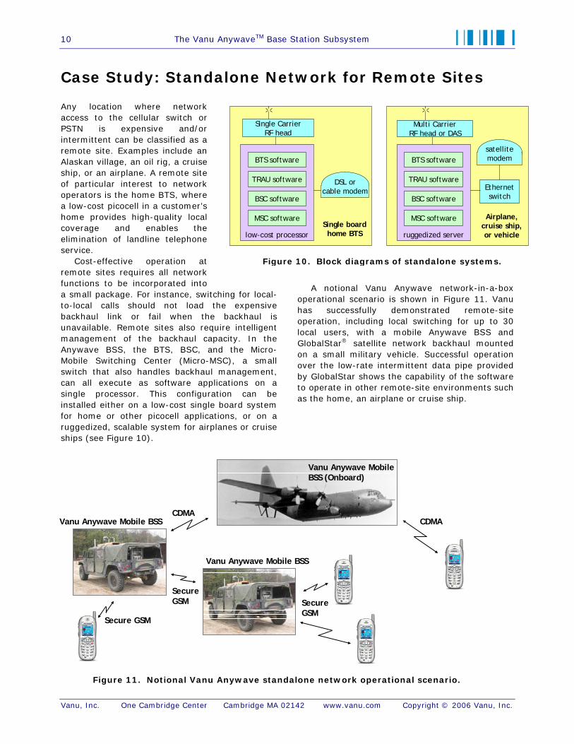
A notional Vanu Anywave network-in-a-box operational scenario is shown in Figure 11. Vanu has successfully demonstrated remote-site operation, including local switching for up to 30 local users, with a mobile Anywave BSS and GlobalStar® satellite network backhaul mounted on a small military vehicle. Successful operation over the low-rate intermittent data pipe provided by GlobalStar shows the capability of the software to operate in other remote-site environments such as the home, an airplane or cruise ship.
ruggedized server
satellitemodem
Ethernetswitch
Airplane,cruise ship,or vehicle
BTS software
TRAU software
BSC software
MSC software
low-cost processor
DSL orcable modem
Single boardhome BTS
BTS software
TRAU software
BSC software
MSC software
Single CarrierRF head
Multi CarrierRF head or DAS
Figure 10. Block diagrams of standalone systems.
CDMACDMA
Vanu Anywave Mobile BSS
Vanu Anywave Mobile BSS
Vanu Anywave Mobile BSS (Onboard)
Secure GSM
SecureGSM Secure
GSM
Figure 11. Notional Vanu Anywave standalone network operational scenario.