THE USE OF FATIGUE MONITORING MWM-ARRAYS IN … · MWM-Array detections are generally consistent...
8
THE USE OF FATIGUE MONITORING MWM-ARRAYS IN PRODUCTION OF NDI STANDARDS WITH REAL FATIGUE CRACKS FOR RELIABILITY STUDIES N. Goldfine 1 , V. Zilberstein 1 , A. Washabaugh 1 , V. Weiss 1 , D. Grundy 1 1 JENTEK Sensors, Inc., Waltham, MA Abstract: This paper describes a new technique for fabrication of nondestructive inspection (NDI) standards with real cracks. This includes cracks in holes, on curved surfaces, on shot peened surfaces, in and under coatings and at buried surfaces. The method uses permanently mounted MWM ® -Array eddy current sensors to detect crack initiation and monitor crack growth. These sensors have been used in fatigue tests of coupons and components as well as full-scale fatigue test articles. This paper describes specific examples for aluminum alloy and low alloy steel specimens. Introduction: Figure 1 provides several examples of scanning and permanently mountable MWM-Array eddy current sensors. Each sensor has one drive winding, consisting of one, two or several rectangular loops. The sensing elements can be either inductive loops or magnetoresistive (MR) sensors. In the case of inductive sensing elements, the transimpedance (sensing element voltage/drive current) is measured for each sensing element. These sensors are carefully designed to enable modeling from basic physical principles and to minimize unmodeled contributions to the sensor response. Each sensing element response at one or more input current frequencies is used by a multivariate inversion routine to determine the absolute property values (electrical conductivity or magnetic permeability) at the location of the sensing element on the test specimen or component. Higher frequencies provide information about near surface properties and lower frequencies provide information about subsurface properties. Databases of precomputed sensor responses are used with a table look-up algorithm to convert complex impedance data into two or more unknown property estimates at each sensing element. In a permanently mounted mode, data is taken at prescribed times. In a scanning mode, data is taken at each sensing element as it traverses a part to produce an image of each unknown property of interest. (a) Scanning 37-channel array (b) Scanning 7-channel array (c) Permanently mountable MWM-Rosette (d) Permanently mountable linear MWM-Array
Transcript of THE USE OF FATIGUE MONITORING MWM-ARRAYS IN … · MWM-Array detections are generally consistent...

THE USE OF FATIGUE MONITORING MWM-ARRAYS IN PRODUCTION OF NDI STANDARDS WITH REAL FATIGUE CRACKS FOR RELIABILITY STUDIES N. Goldfine1, V. Zilberstein1, A. Washabaugh1, V. Weiss1, D. Grundy1
1JENTEK Sensors, Inc., Waltham, MA Abstract: This paper describes a new technique for fabrication of nondestructive inspection (NDI) standards with real cracks. This includes cracks in holes, on curved surfaces, on shot peened surfaces, in and under coatings and at buried surfaces. The method uses permanently mounted MWM®-Array eddy current sensors to detect crack initiation and monitor crack growth. These sensors have been used in fatigue tests of coupons and components as well as full-scale fatigue test articles. This paper describes specific examples for aluminum alloy and low alloy steel specimens. Introduction: Figure 1 provides several examples of scanning and permanently mountable MWM-Array eddy current sensors. Each sensor has one drive winding, consisting of one, two or several rectangular loops. The sensing elements can be either inductive loops or magnetoresistive (MR) sensors. In the case of inductive sensing elements, the transimpedance (sensing element voltage/drive current) is measured for each sensing element.
These sensors are carefully designed to enable modeling from basic physical principles and to minimize unmodeled contributions to the sensor response. Each sensing element response at one or more input current frequencies is used by a multivariate inversion routine to determine the absolute property values (electrical conductivity or magnetic permeability) at the location of the sensing element on the test specimen or component. Higher frequencies provide information about near surface properties and lower frequencies provide information about subsurface properties.
Databases of precomputed sensor responses are used with a table look-up algorithm to convert complex impedance data into two or more unknown property estimates at each sensing element. In a permanently mounted mode, data is taken at prescribed times. In a scanning mode, data is taken at each sensing element as it traverses a part to produce an image of each unknown property of interest.
(a) Scanning 37-channel array
(b) Scanning 7-channel array
(c) Permanently mountable MWM-Rosette
(d) Permanently mountable linear MWM-Array

Figure 1: Examples of scanning and surface mountable/embeddable MWM-Arrays.
The remainder of this paper provides some examples of fatigue tests with MWM-Array monitoring. Figure 2 shows four examples of specimen configurations used in these tests. The focus is on the capability to generate specimens with real cracks that represent the actual cracks seen in service or similar to cracks formed as a result of manufacturing deficiencies. This is a critical need as crack detection requirements become more severe. Crack morphology variations are a major source of NDI response variation, not only for eddy current sensing but also for other methods such as penetrant testing and ultrasonic testing. Thus, specimens with cracks grown without starter notches not only in machined but also in shot peened or coated materials can provide real value in assessing true NDI performance under probability of detection (POD) and other performance studies. Existing methods to grow cracks from EDM notches and then remove the notches are impractical for shot peened parts, since the shot peened surface would be removed. Also, for growing cracks under coatings and on complex components, cracks created without starter notches are essential to test real NDI performance. Moreover, small and shallow fatigue cracks initiated without starter notches tend to form in clusters and are not necessarily aligned. Thus, they are representative of small cracks observed in real structures. Small cracks in such clusters can be missed by differential eddy current sensors and also by a number of other conventional NDI methods.
Figure 3 provides schematics of each of the sensors used for fatigue monitoring of the specimens shown in Figure 2. Each of these are 7-channel MWM-Arrays. In the specimens shown in Figures 2(b) and 2(d), networks of two or more arrays are used to monitor different locations. MWM-Arrays are either mounted between layers to monitor crack initiation and growth as shown in Figures 2(c) and 2(d) or on curved surfaces with as-manufactured conditions, e.g., shot peened or coated to emulate actual components, see Figures 2(a) and 2(b).
Figure 4 provides examples of actual MWM-Array data from fatigue tests with the corresponding specimen geometries and sensors shown in Figures 2 and 3. Figure 4(a) shows results from a fatigue test of a shot peened 4340 low alloy steel specimen. This test was stopped when the MWM-Array detected accelerated growth of cracks at two locations. After the test, the area was scanned with a scanning MWM-Array. Figure 5 shows an image of the magnetic permeability produced with the MWM-Array shown in Figure 1(a). This image reveals a fatigue damage zone with cracks at the two locations identified first by the permanently mounted MWM-Array during the fatigue test. These cracks were not detected using conventional eddy current test (ET), ultrasonic test (UT) or fluorescent penetrant testing performed by Level III inspectors at an aerospace original equipment manufacturer (OEM). An examination in a scanning electron microscope (SEM) confirmed the presence of the cracks at these two locations, but the longest crack detected in the SEM was only 200 µm (0.008 in.) long at the surface. Figure 5 also shows a photomicrograph from a location with a crack that appears to be about 90 µm long. Subsequently performed fractography detected two cracks that are significantly longer than the cracks revealed by SEM. The MWM-Array detections are generally consistent with the fractography findings.
(a) Specimen with a shot peened curved surface that may be coated or plated (a close-up of a surface mounted
MWM-Array is shown on the right).

(b) Specimen with a hole and two internally mounted MWM-Arrays.
(c) Specimen with MWM-Rosettes mounted around a fastener hole and embedded between two layers.
(d) Four-hole specimen and a schematic with 3 linear MWM-Arrays embedded between layers.
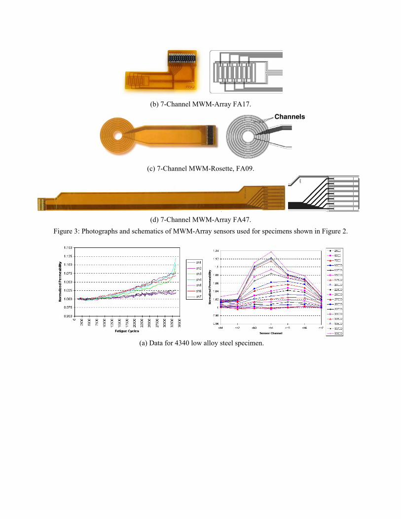
Figure 2: Photographs of four tension-tension fatigue specimen types illustrating sensor placement (see Figures 3 and 4 for sensor schematics and results). Using a specimen configuration similar to that shown in Figure 2(b), with sensors mounted in the hole, tests have been stopped with cracks as small as 40 µm. Furthermore, recent tests reveal that lift-off data may provide a measure of surface roughening related to precrack fatigue damage.
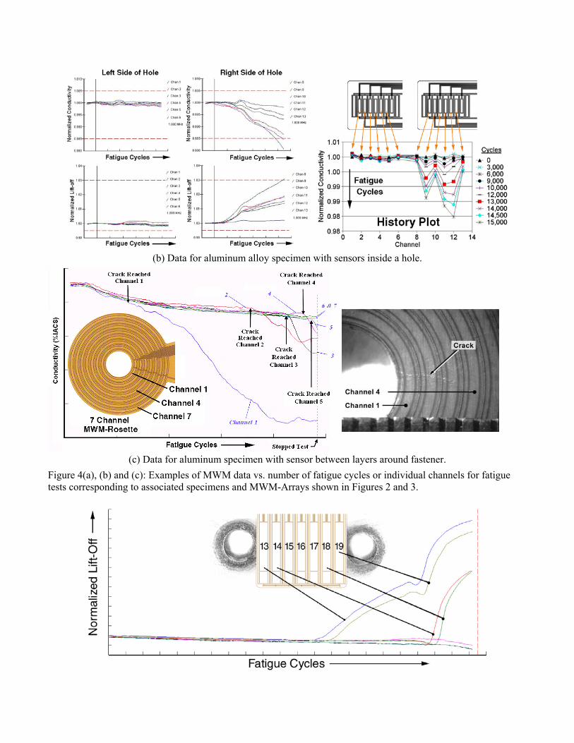
Figure 6 shows a broken 4-hole specimen with MWM-Arrays mounted between the layers (for additional details, see Figures 2(d), 3(d) and 4(d)). Here, the embedded MWM-Arrays proved to be durable enough to outlast the fatigue specimen. Tests have been run in excess of 38,000 cycles with such embedded MWM-Array sensor networks (see Figure 4(d)).
(a) 7-Channel MWM-Arrays FA22 and FA23.
(b) 7-Channel MWM-Array FA17.
(c) 7-Channel MWM-Rosette, FA09.
(d) 7-Channel MWM-Array FA47.
Figure 3: Photographs and schematics of MWM-Array sensors used for specimens shown in Figure 2.
(a) Data for 4340 low alloy steel specimen.
(b) Data for aluminum alloy specimen with sensors inside a hole.
(c) Data for aluminum specimen with sensor between layers around fastener.
Figure 4(a), (b) and (c): Examples of MWM data vs. number of fatigue cycles or individual channels for fatigue tests corresponding to associated specimens and MWM-Arrays shown in Figures 2 and 3.

(d) Data for aluminum four hole specimen with sensors between layers.
Figure 4(d): Examples of MWM data vs. number of fatigue cycles for individual channels acquired during fatigue tests corresponding to associated specimens and MWM-Arrays shown in Figures 2 and 3.
Figure 5. MWM-Array image and photomicrograph of 90-µm long crack found by SEM for specimen referenced in Figures 2(a), 3(a), and 4(a).
(a)
(b)
(c)
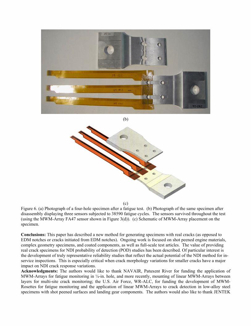
Figure 6. (a) Photograph of a four-hole specimen after a fatigue test. (b) Photograph of the same specimen after disassembly displaying three sensors subjected to 38590 fatigue cycles. The sensors survived throughout the test (using the MWM-Array FA47 sensor shown in Figure 3(d)). (c) Schematic of MWM-Array placement on the specimen. Conclusions: This paper has described a new method for generating specimens with real cracks (as opposed to EDM notches or cracks initiated from EDM notches). Ongoing work is focused on shot peened engine materials, complex geometry specimens, and coated components, as well as full-scale test articles. The value of providing real crack specimens for NDI probability of detection (POD) studies has been described. Of particular interest is the development of truly representative reliability studies that reflect the actual potential of the NDI method for in-service inspections. This is especially critical when crack morphology variations for smaller cracks have a major impact on NDI crack response variations. Acknowledgments: The authors would like to thank NAVAIR, Patuxent River for funding the application of MWM-Arrays for fatigue monitoring in ¼-in. hole, and more recently, mounting of linear MWM-Arrays between layers for multi-site crack monitoring; the U.S. Air Force, WR-ALC, for funding the development of MWM-Rosettes for fatigue monitoring and the application of linear MWM-Arrays to crack detection in low-alloy steel specimens with shot peened surfaces and landing gear components. The authors would also like to thank JENTEK

Sensors, Inc. and the entire team at JENTEK for supporting this research. The opinions in this paper are those of the authors and not the sponsoring agencies. References: Goldfine, N., Zilberstein, V., A. Washabaugh, D. Schlicker, I. Shay, D. Grundy, “Eddy Current Sensor Networks for Aircraft Fatigue Monitoring,” Materials Evaluation, Volume 61, No. 7, July 2003, pp. 852-859, ASNT.
Goldfine, N.J., Zilberstein, V., Cargill, J.S., Schlicker, D., Shay, I., Washabaugh, A., Tsukernik, V., Grundy, D., Windoloski, M., “MWM-Array eddy current sensors for detection of cracks in regions with fretting damage,” Materials Evaluation, July 2002, Volume 60, pp. 870-877, ASNT.
Zilberstein, V., Walrath, K., Grundy, D., Schlicker, D., Goldfine, N., Abramovici, E., Yentzer, T., “MWM Eddy-Current Arrays for Crack Initiation and Growth Monitoring,” Published, International Journal of Fatigue, Volume 25, 2003, pp. 1147-1155.
Zilberstein, V., Fisher, M., Grundy, D., Schlicker, D., Tsukernik, V., Vengrinovich, V., Goldfine, N. “Residual and applied stress estimation from directional magnetic permeability measurements with MWM sensors,” Journal of Pressure Vessel Technology, August 2002: Volume 124, 375-381.
Zilberstein V., Schlicker D., Walrath K., Weiss V., Goldfine N. “MWM eddy current sensors for monitoring of crack initiation and growth during fatigue tests and in service,” International Journal of Fatigue, 2001, Supplement: S477 – S485.