The University of Texas at Arlington Lecture 7 Addressing ...
21
The University of Texas at Arlington 1 Lecture 7 Addressing, Tables, Banks, Memory CSE 3442/5442 2 2 Addressing Methods • Immediate Addressing – Operand part of the instruction (constant K) • Direct Addressing – Instruction has the operand of a RAM address and thus can be directly addressed • Register Indirect Addressing – Kind of like using pointers to address registers. There are specific SFRs set aside for this.
Transcript of The University of Texas at Arlington Lecture 7 Addressing ...

The University of Texas at Arlington
1
Lecture 7Addressing, Tables, Banks, Memory
CSE 3442/5442
22
Addressing Methods
• Immediate Addressing– Operand part of the instruction (constant K)
• Direct Addressing– Instruction has the operand of a RAM
address and thus can be directly addressed• Register Indirect Addressing
– Kind of like using pointers to address registers. There are specific SFRs set aside for this.

33
Immediate Addressing
• Operand is part of the instruction, thus ‘immediately’ available when instruction is fetched.
• E.g.,MOVLW 0X25 ; 25H WREGANDLW B’01000000 ;AND WREG with 40H
Or using EQU•COUNT EQU 0x30•MOVLW COUNT ; 30H WREG ; Assembler insures 30H placed in the second byte of the instruction
• RAM cannot be immediately addressed (i.e., there is no MOVKF).
44
Direct Addressing
• Operand is obtained from or to file register. • MOVLW 0X25 ; 25H WREG (literal)• MOVWF 0x45 ; MOVE CONTENTS OF WREG
; TO FILE REGISTER
MOVFF 0x40, 0x50 ; (40H) (50H)
• Note the MOVWF only access the current bank while the MOVFF instruction can access all of the 4K RAM address space (recall, that File register (RAM) arranged into 16 Banks of 256 bytes).

55
Bank Addressing
• Direct Addressing Instructions take two bytes, one for the operation code and the other for an 8 bit 256 byte Access Bank address. Thus will need way to access the other banks (later).
66
Register Indirect Addressing
• Special register is used as a pointer (actually three of them)• FSRs (File Register Select) are 12 bit registers: FSR0, FSR1,
FSR2. Each is represented by two SFRs, e.g., FSR0 has FSR0L and FSR0H.– LFSR 1, 0x030 ; load 0x30 into FSR 1– LFSR 0, 0x130 ; load 0x130 into FSR 0
• The file register that the FSR is pointing to can be than reached in INDF0, INDF1, and INDF2, respectively.– LFSR 0, 0x130– MOVWF INDF0 ; contents of W moved to fileReg 0x130
• Effective for array (string) operations• There are instructions for incrementing FRSs and clearing memory
locations to which FSR points.

77
FSR0-2 Registers Used for Register Indirect
• Each FSR0-2 register is 12 bits thus consisting of two one byte file registers.
• The low order 8 bits are in one byte (FSRxL) and the upper 4 bits in the low order bits (or nibble) of the second byte (FSRxH).
Register Function Address
FSROL Indirect data memory address pointer 0 low FE9HFSROH Indirect data memory address pointer 0 high FEAHFSR1L Indirect data memory address pointer 1 low FE1HFSR1H Indirect data memory address pointer 1 high FE2HFSR2L Indirect data memory address pointer 0 low FD9HFSR2L Indirect data memory address pointer 0 low FDAH
88
Example Using FSRx and INDFxRegisters
• Copy 55H to RAM locations 40H to 43H• Direct Addressing
MOVLW 0x55 ; WREG = 55HMOVWF 0X40 ; Copy WREG to RAM 40HMOVWF 0X41 ; Copy WREG to RAM 41HMOVWF 0X42 ; Copy WREG to RAM 42H
• Using Register indirect (w/o loop)MOVLW 0x55 ; WREG = 55HLSFR 0x40 ; Load the pointer, FSR0 w/ 40HMOVWF INDF0 copy W to loc FSR0 point toINCF FSR0L,F ;increment pointer FSR0=41HMOVWF INDF0 copy W to loc FSR0 point toINCF FSR0L,F ;increment pointer FSR0=42HMOVWF INDF0 copy W to loc FSR0 point to

99
Register Indirect Advantages
• Allows for dynamic Data referencing • For example - Sending a string of data
located in consecutive memory locations is more efficient using Register Indirect addressing than using Direct addressing as only need to increment pointer in FSRxL
1010
Useful Instruction for Work with the FSR Registers
• CLRF INDFn After clearing fileReg pointed to by FSRn, the FSRn stays the same
• CLRF POSTINCn After clearing fileReg pointed to by FSRn, the FSRn is incremented
• CSRF PREINCn The FSRn is incremented, then fileRegpointed to by FSRn, is cleared
• CLRF POSTDECn After clearing fileReg pointed to by FSRn, the FSRn is decremented
• CLRF PLUSWn Clears fileReg pointed to by (FSRn + WREG), FSRn & W unchanged.
• Note: The auto-increment/decrement affects the entire 12 bits of FSRn and has no effect on Status register. Thus FSRn going from FFF to 000 will not be detected by the flags.
1111
FSR Auto-increment
5
1212
Lookup Tables
• Instead of calculating, sometimes storing lookup tables is more efficient (e.g., cosine tables, square tables, etc.)
• Lookup tables can be stored as instructions in the ROM.
• RETLW K is a return from subroutine command that copies K into WREG as well. This can be used easily for lookup tables.
1313
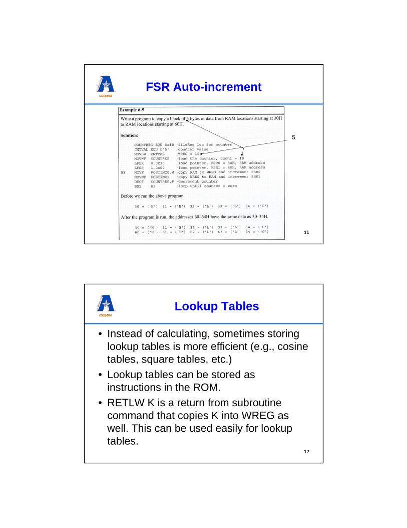
Square Lookup Table ExampleORG 0HSETF TRISBCLRF TRISC
LP1 MOVF PORTB, WANDLW 0x0FCALL SQTBMOVWF PORTCBRA LP1
SQTBMULLW 0x02 ;align to even address (multiply by two)MOVFF PRODL, WREGADDWF PCLRETLW 0x0RETLW 0x1RETLW 0x4RETLW 0x9RETLW 0x10RETLW 0x19RETLW 0x24::END
1414
Storing Data in ROM
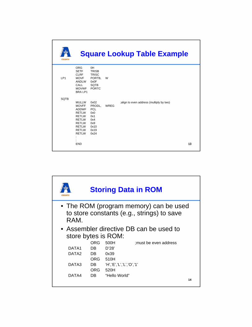
• The ROM (program memory) can be used to store constants (e.g., strings) to save RAM.
• Assembler directive DB can be used to store bytes is ROM:
ORG 500H ;must be even addressDATA1 DB D’28’DATA2 DB 0x39
ORG 510HDATA3 DB ‘H’,’E’,’L’,’L’,’O’,’1’
ORG 520HDATA4 DB “Hello World”
1515
Reading Data from ROM
• Register indirect ROM addressing, i.e., accessing ROM is done through SFR registers.
• A.k.a. table processing• TBLPTR is a 21 bit register (TBLPTRL,
TBLPTRH, TBLPTRU) pointing to the data accessed in ROM
• TBLAT (table latch) is used to copy the data pointed by TBLPTR, once instructed.
• (There is also a TBLWRT instruction but works only on PICs that have flash ROM –implications?)
1616
Reading Data from ROM (cont’d)
• TBLRD* read the table, TBLPTR remains unchanged
• TBLRD*+ read the table, TBLPTR is incremented
• TBLRD*- read the table, TBLPTR is decremented
• TBLRD+* increment TBLPTR then read
• Read is always into TABLAT

1717
Bank Switching
• Max 4K of RAM (in PIC18 but not all have max)• Only 256bytes are addressable• RAM is divided into a max of 16 banks• Default bank’s lower 128 bytes are general
purpose, while upper 128 are the SFR• MOVWF fileReg , A
– Until now we have ignored A– If A=0 then default bank is used– If A=1 then bank selector register is used to
determine bank
1818
Bank Selector Register
• Bank Selector Register (BSR) is an 8 bit register in the SFR
• Only the 4 LSBs are used• If using the BSR, then bank 0 is a continuous
00F-FFH and bank FH’s upper 128 bytes are the SFR (as in the RAM map)
• Default value for BSR is 0• Thus if need to use other banks:
1. Load BSR with the desired banks number MOVLB instructio can be helpful
2. Use A=1 in the instructions
• INCF MYREG, F, 0 vs. INCF MYREG, F, 1

1919
Bank Selector Register Example
MYREG EQU 0x40
MOVLB 0x2 ; use bank 2MOVLW 0MOVWF MYREG, 1 ;loc 0x240=0INCF MYREG, F, 1 ; loc 0x240=1INCF MYREG, F, 1 ; loc 0x240=2
• What would happen if we omitted the 1 at the end of the instructions?
• This seemingly additional operand is encoded in the instruction op code, just like the F/W. The 2 LSBs in applicable instruction opcodes are F/W and A (LSB) respectively.
2020
Moving Data Between RAM Registers
• MOVFF can move data between any RAM registers without the need for BSR
• This is possible because MOVFF is 4 byte instruction (8 bits of opcode, 2*12 bits for address = 32 bits total)

2121
Macros and Modules
• Macro is used for referencing the same group of instructions repeatedly. Thus do not have to repeat the instructions each time instruction group are used.
• Understand the difference between a macro and a subroutine!name MACRO substitute1, … , substituteN
macro bodyEndM
E.g.:MOVLF MACRO K, MYREG ; useful instruction
MOVLW KMOVWF MYREGENDM
2222
Other Assembler Directives
• Local – Use to keep names (i.e., labels) local to Macro (e.g., if macro had a local jump inside)
• Use INCLUDE directive to reference macros/code defined in other files
• Use NOEXPAND/EXPAND to prevent showing or showing macro code in listing files.

23
Some C Issues
2424
C Integer Data Types
[-2 147 483 648,2 147 483 648]32long[0,4 294 967 295]32unsigned long
[-8 388 608,8 388 607]24short long[0,16 777 215]24unsigned short long
[-32 768,32 767]16int(or short)
[0,65 535]16unsigned int (or short)[-128,127]8char
[0,255]8unsigned charRangeSize (bits)Data Type

2525
Working With Data in ROM Using C
2626
Using Near
• near and far can be used to control where the data in the ROM should be (in low 64K or anywhere)
• More efficient use of code space

2727
Using Far
2828
Placing Code at a Specific Address
• #pragma code function_name = addresscan be used to move functions to specific addresses
– E.g., #pragma code main = 0x30– E.g., #pragma code MSDelay = 0x400

2929
Putting Data at Specific LocationsThe ORG Equivalent in C
3030
Data at Specific RAM Addresses
• Simple/explicit in assembly• #pragma is used in C
– idata: initilized data#pragma idata mydata = 0x150unsigned char mydata[] = “Hello”;
– udata: unitialized data#pragma udata mydata = 0x250far unassigned char mydata[100];
• However, they really should not be used as it is the task of the compiler to find good locations for them. There may be reasons to use this (e.g., mixed assembly/C programming)

3131
Idata Example
3232
Overlay Variables
• Two variables can use the same space if they are not used at thesame time
• The compiler may decide to use the same physical location for variables x and y in the following two functions:
unsigned char functionA(void){
overlay unsigned int x=0;x++;return x;
}
unsigned char functionB(void){
overlay unsigned int y=5;y--;return y;
}
• What would happen if functionA called functionB?
33
Writing to Non-volatile Memory
34
Non-Volatile Memory in PICs
• In addition to the volatile (but flip-flop based and thus stabile) SRAM, there are two kinds of non-volatile memory integrated into PIC18F-s:– Flash EPROM, this is the memory in which firmware is uploaded– EEPROM memory, intended for storing variables that should not
be reset• Why not only use one kind?
– EEPROM is more expensive, but it can be rewritten byte-by-byte. Flash EPROM, before rewriting, requires a block erase (flashing it) and can only be written one block at a time.
• In general, electrically erasable programmable ROM can only be rewritten a limited amount of times before being damaged (~100k times).

35
Erasing and Writing into Flash
• We have seen earlier that data can be read from the program memory, using an indirect read operation through a TABLAT register, TBLPTR pointers, and TBLRD commands.
• Writing into a Flash block can only take place if the block is empty, i.e., it has been previously erased either through a programmer or from firmware.
• If erasing Flash from firmware, block sizes are 64-bytes (lower 6 bits do not matter).
• When writing (burning) to Flash from firmware, block sizes are 8 bytes (lower 3 bits do not matter)
36
Writing to Flash from Firmware
• Blocks of 8 bytes need to be written.• TBLWT instructions are used
– TBLWT* after write TBLPTR remains the same– TBLWT*+ write and then increment TBLPTR– TBLWT*- write and then decrement TBLPTR– TBLWT+* increment TBLPTR and then write
• TABLAT actually has an 8 byte wide shadow that all 8 bytes of the block need to be loaded with using short TBLWT-s.
• Then, a long write command set needs to be issued to write the shadow registers into the Flash

37
Writing to Flash from Firmware (cont’d)
;Loading “Embedded” into Flash Rom at 0x1000;short writes:MOVLW 0x00 ; lower 3 bits need to be 0MOVWF TBLPTRLMOVLW 0x10MOVWF TBLPTRHMOVLW 0x00MOVWF TBLPTRUMOVLW A’E’MOVFW TABLAT MOVLW A’m’MOVFW TABLAT MOVLW A’b’MOVFW TABLAT MOVLW A’e’MOVFW TABLAT MOVLW A’d’MOVFW TABLAT MOVLW A’d’MOVFW TABLAT MOVLW A’e’MOVFW TABLAT MOVLW A’d’MOVFW TABLAT
;long write cycleMOVLW 0x00MOVWF TBLPTRLMOVLW 0x10MOVWF TBLPTRHMOVLW 0x00MOVWF TBLPTRUBSF EECON1, EEPGD ;EECON1 controls FlashBCF EECON1, CFGS ; select FlashBSF EECON1, WREN ; enable writing to FlashBCF INTCON, GIE ; disable interruptsMOVLW 55H ; doing the needfulMOVW EECON2 ; EECON2 is a write only dummyMOVLW 0AAHMOVW EECON2BSF EECON1, WR ; write!NOP ; it will take about 2ms for write
; operation ,CPU is stalledBSF INTCON, GIE ; re-enable interruptsBCF EECON1, WREN ; disable writing to Flash
38
EECON1 Register

39
Erasing Flash Memory; erasing 64 byte block block at 0x1000MOVLW 0x00 ; lower 6 bits need to be 0MOVWF TBLPTRLMOVLW 0x10MOVWF TBLPTRHMOVLW 0x00MOVWF TBLPTRUBSF EECON1, EEPGD ; select FlashBCF EECON1, CFGS ; select FlashBSF EECON1, WREN ; enable writeBSF EECON1, FREE ; enable eraseBCF INITCON, GIE ; disable interruptsMOVLW 55H ; doing the needfulMOVW EECON2 ; EECON2 is a write only dummyMOVLW 0AAHMOVW EECON2BSF EECON1, WR ; write!NOP ; it will take about 2ms for write
; operation, CPU is stalledBSF INTCON, GIE ; re-enable interruptsBCF EECON1, WREN ; disable writing to Flash
• How about doing the writing and erasing from C?
• Erasing is simple, just use C instead of assembly.
• It needs assembly code for TBLWT inserted into C using the _asm _endasmdirective.
• (see textbook page 551)
40
Reading from EEPROM
• EEPROM is only for data (unlike Flash)• It has its own memory address starting from 0• In addition to EECON1 and EECON2, two more registers
are used:– EEADR: 8 bit register used as a pointer to EEPROM (like
TBLPTR) (may be more than one register if more than 256B)– EEDATA: 8 bit register for data (like TBLAT)
MOVLW 0x10 ; read from EEPROM location 10HMOVWF EEADR ;set pointerBCF EECON1, EEPGD ; activate EEPROM programBCF EECON1, CFGSBSF EECON1, RD ; enable readNOP ; data is fetched MOVFF EEDATA, PORTB ; move data to PORTB - optional

41
Writing to EEPROM
MOVLW 0x10 ; write into EEPROM at location 10HMOVWF EEADR ; set pointerMOVLW A’Z’ ; letter ‘Z’ is to be written at EEPROM 10HMOFWF EEDATABCF EECON1, EEPGD ; activate EEPROM programBCF EECON1, CFGSBSF EECON1, WREN ; enable writeBCF INTCON, GIE ; disable all interruptsMOVLW 55H ; do the EECON2 mumbo-jumboMOVW EECON2 MOVLW 0AAHMOVW EECON2BSF EECON1, WR ; write!BSF INTCON, GIE ; re-enable interruptsBCF EECON1, WREN ; disable wirte
42
Summary
• We have learned about different memory types:– Immediate– Direct– Register Indirect
• and different accessing methods– Data memory, using SRAM flip-flops– Program ROM implemented by Flash memory– Non-volatile RAM implemented by EEPROM
• We have also looked at basic C programming ways to access these memories