The University of Anytown School of Business Computing.
49
The University of Anytown School of Business Computing
-
Upload
kellie-spencer -
Category
Documents
-
view
225 -
download
1
Transcript of The University of Anytown School of Business Computing.
The University of Anytown
School of Business Computing
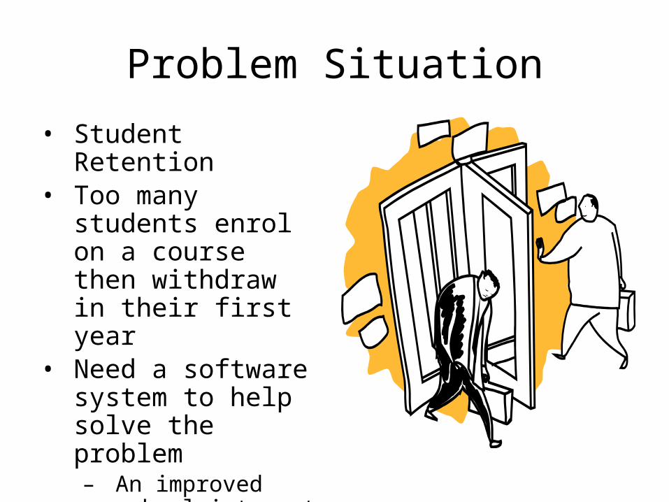
Problem Situation
• Student Retention• Too many students
enrol on a course then withdraw in their first year
• Need a software system to help solve the problem– An improved school
intranet
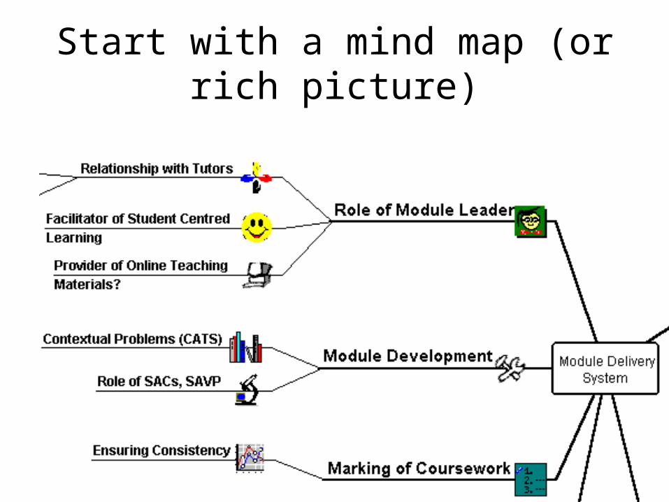
Start with a mind map (or rich picture)
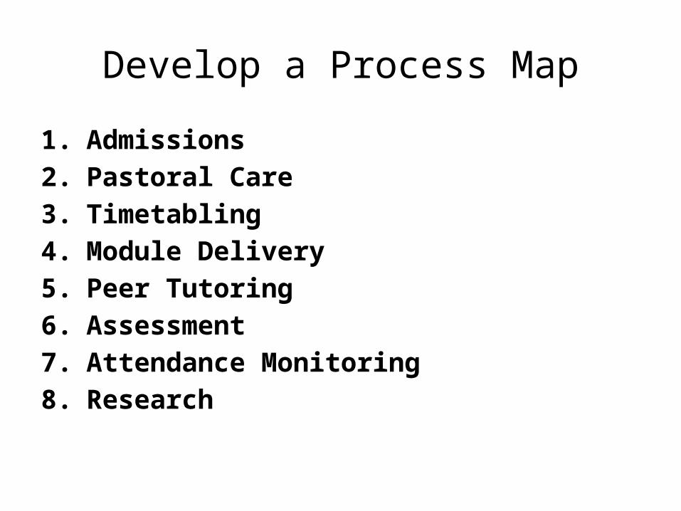
Develop a Process Map
1. Admissions 2. Pastoral Care3. Timetabling 4. Module Delivery5. Peer Tutoring6. Assessment7. Attendance Monitoring8. Research
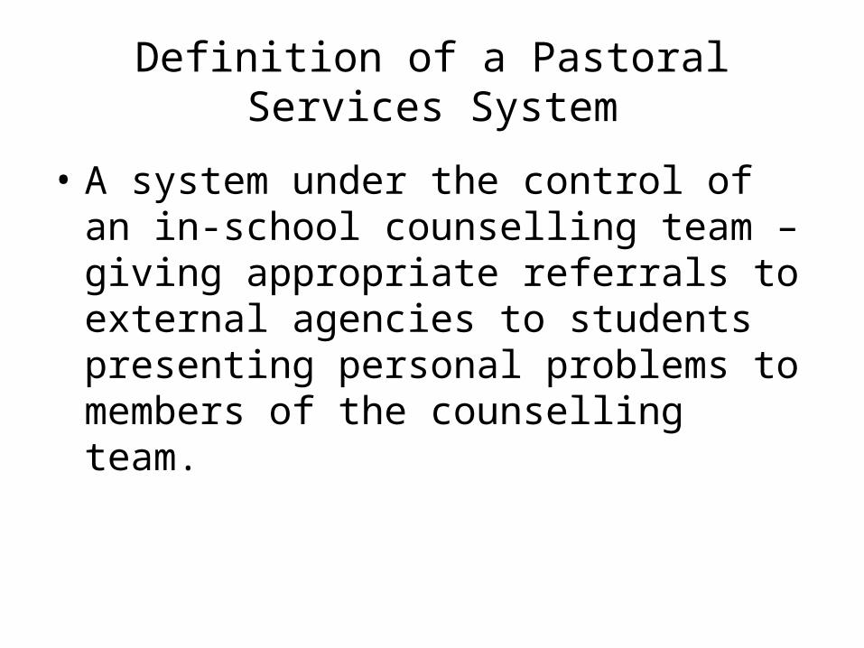
Definition of a Pastoral Services System
• A system under the control of an in-school counselling team – giving appropriate referrals to external agencies to students presenting personal problems to members of the counselling team.
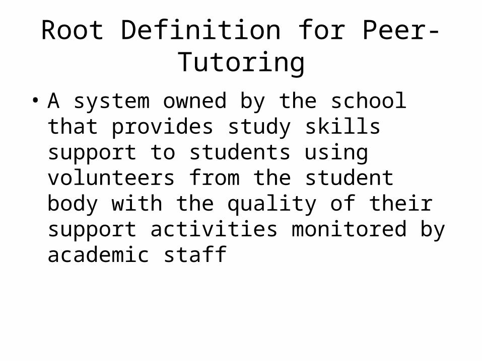
Root Definition for Peer-Tutoring
• A system owned by the school that provides study skills support to students using volunteers from the student body with the quality of their support activities monitored by academic staff

Activity Diagram for Peer-Tutoring
Identify Suitable Peer Tutors
Document Skills of Peer Tutors
Train Peer Tutors
Advertise
Document Tutee Needs
Receive Tutee
Book times and rooms
Tutee Recruitment Sub SystemPeer Tutor Recruitment Sub System
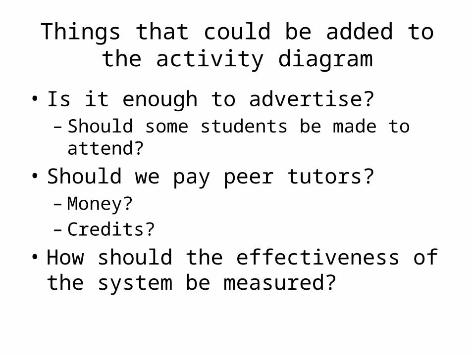
Things that could be added to the activity diagram
• Is it enough to advertise?– Should some students be made to attend?
• Should we pay peer tutors?– Money?– Credits?
• How should the effectiveness of the system be measured?
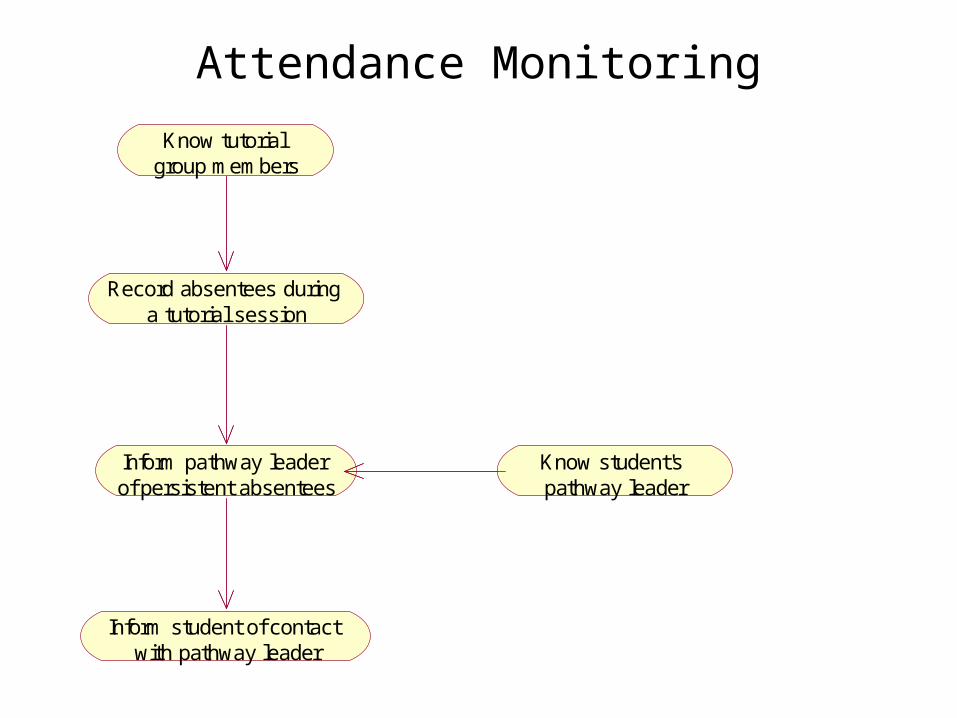
Attendance Monitoring
Record absentees during a tutorial session
Know tutorial group members
Inform pathway leader of persistent absentees
Know student's pathway leader
Inform student of contact with pathway leader
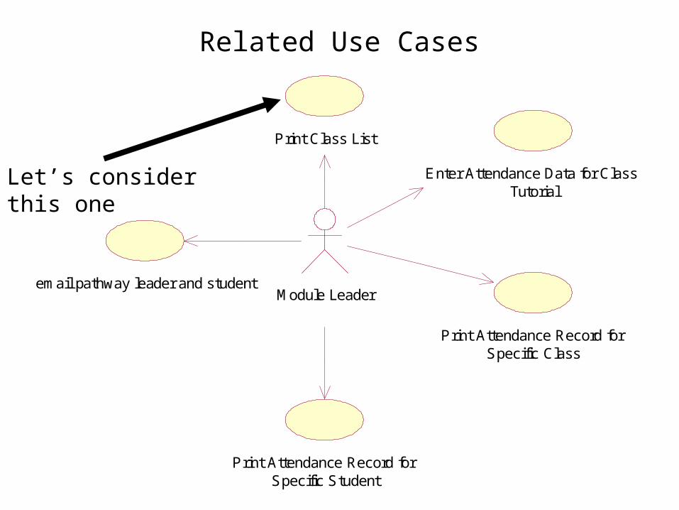
Related Use Cases
Print Class List
Enter Attendance Data for Class Tutorial
Print Attendance Record for Specific Class
Print Attendance Record for Specific Student
Module Leaderemail pathway leader and student
Let’s consider this one
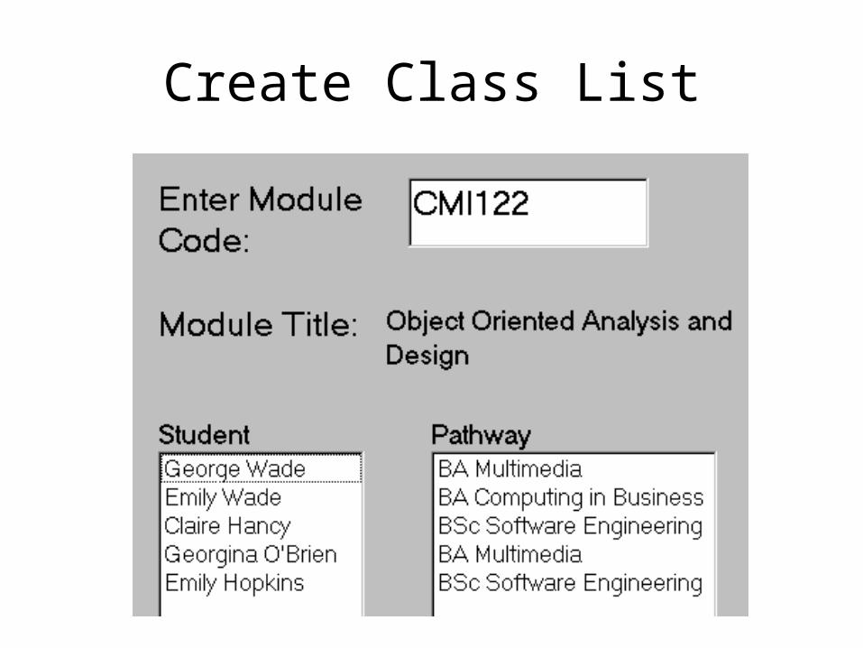
Create Class List
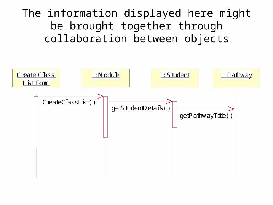
The information displayed here might be brought together through collaboration between objects
: Pathway : Module : StudentCreate Class List Form
CreateClassList( )getStudentDetails( )
getPathwayTitle( )
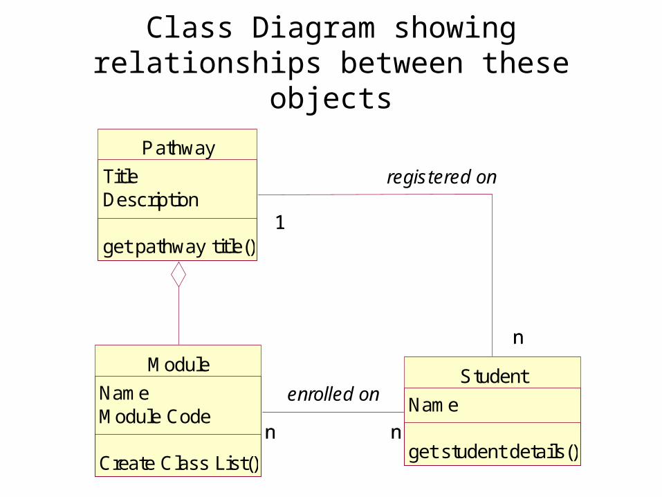
Class Diagram showing relationships between these objects
Module
NameModule Code
Create Class List()
Student
Name
get student details()n nn n
enrolled on
Pathway
TitleDescription
get pathway title()1
nn
1
registered on
We can do two things with this class diagram
• Implement it in an OOPL• Translate it into an entity model then
implement the entity model as a relational database
• CASE tools can help with both of these
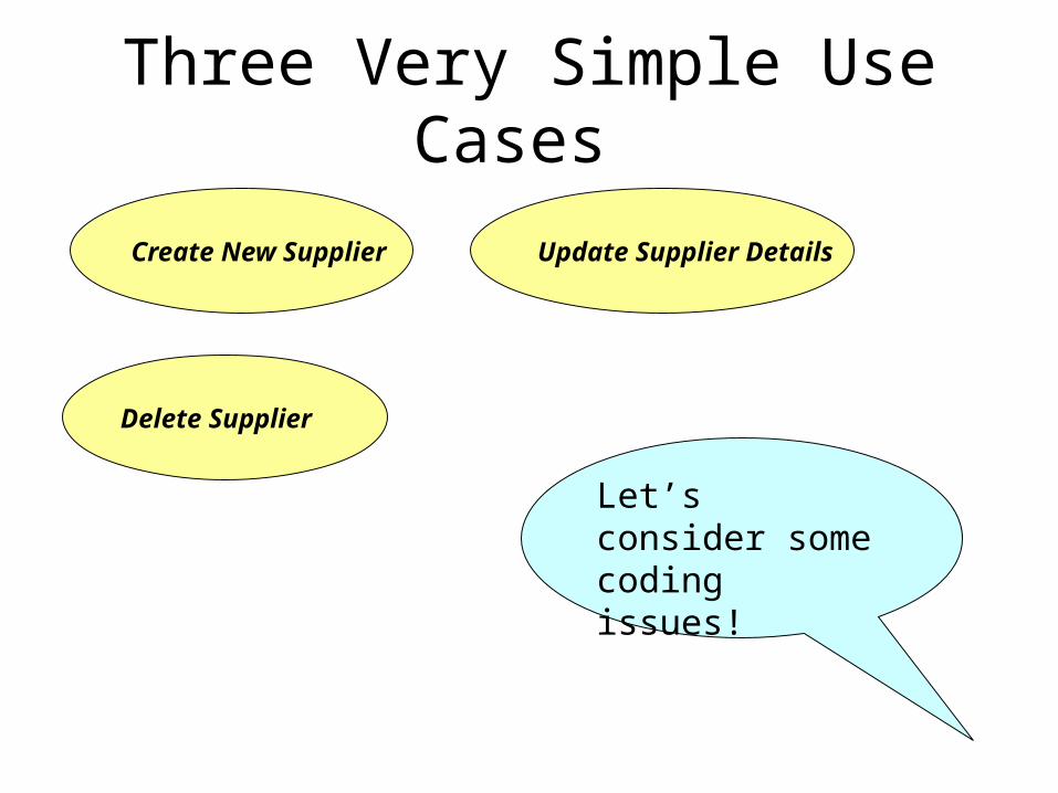
Three Very Simple Use Cases
Create New Supplier
Delete Supplier
Update Supplier Details
Let’s consider some coding issues!
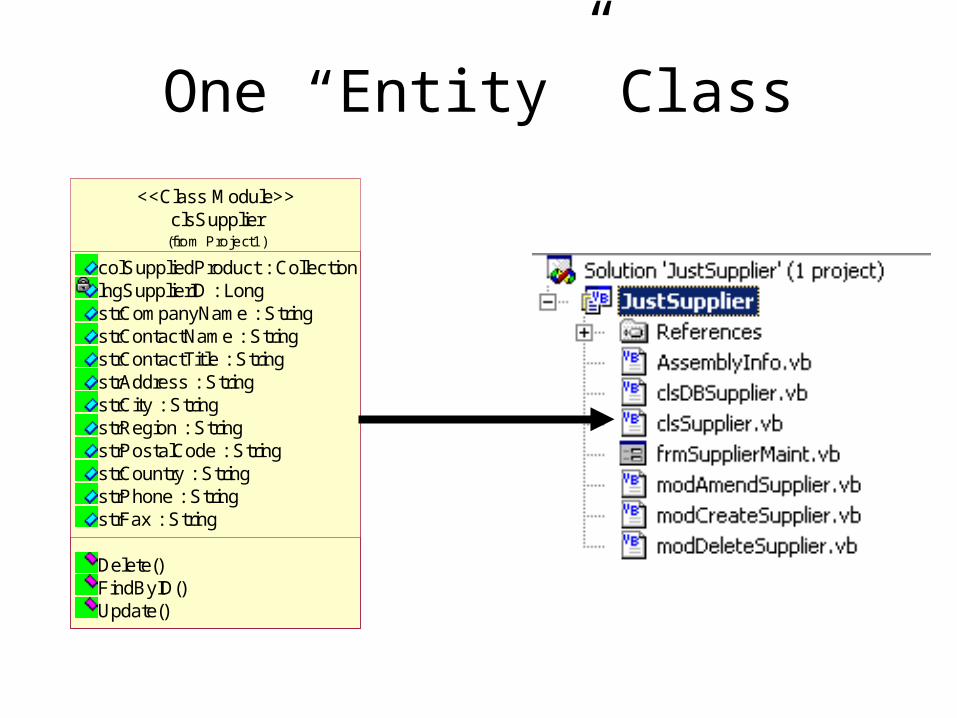
One “Entity” Class
clsSupplier
colSuppliedProduct : CollectionlngSupplierID : LongstrCompanyName : StringstrContactName : StringstrContactTitle : StringstrAddress : StringstrCity : StringstrRegion : StringstrPostalCode : StringstrCountry : StringstrPhone : StringstrFax : String
Delete()FindByID()Update()
(from Project1)
<<Class Module>>
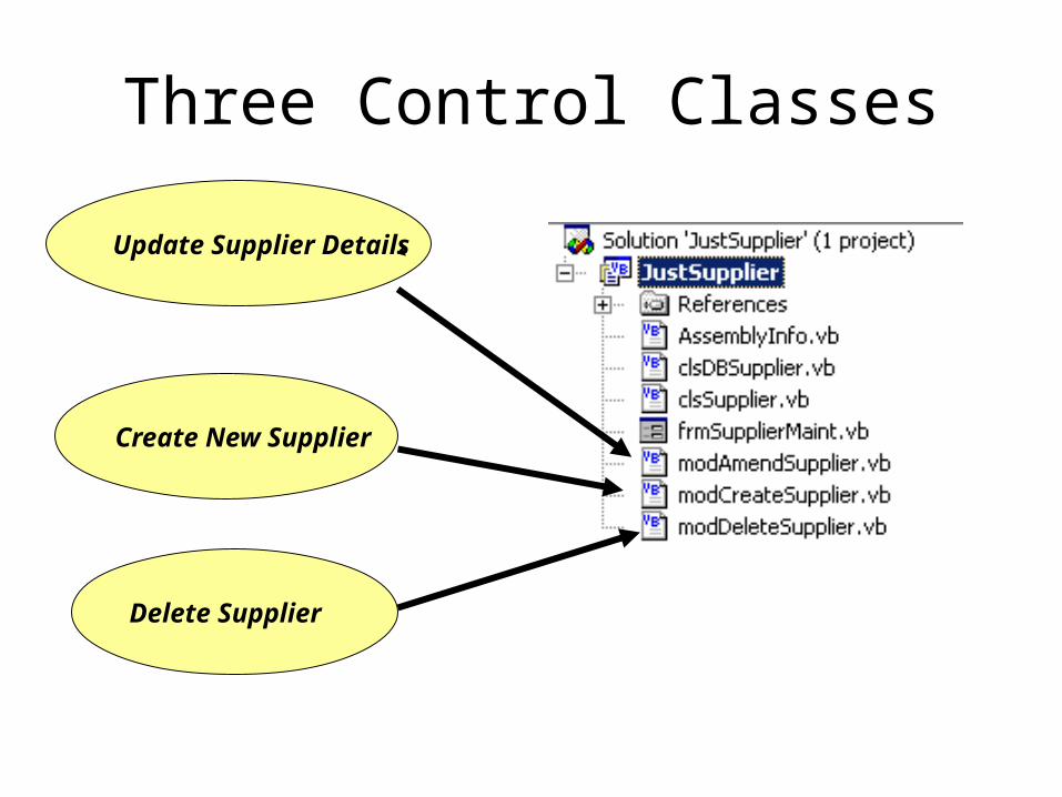
Three Control Classes
Create New Supplier
Delete Supplier
Update Supplier Details

One Boundary Class for all Three Use Cases
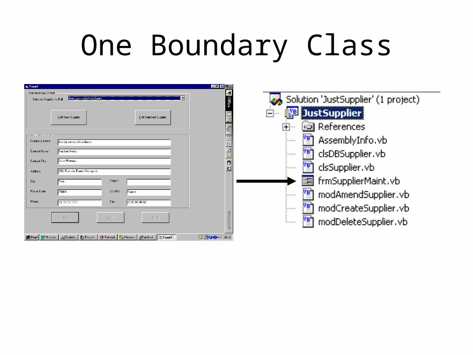
One Boundary Class
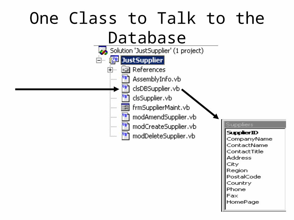
One Class to Talk to the Database
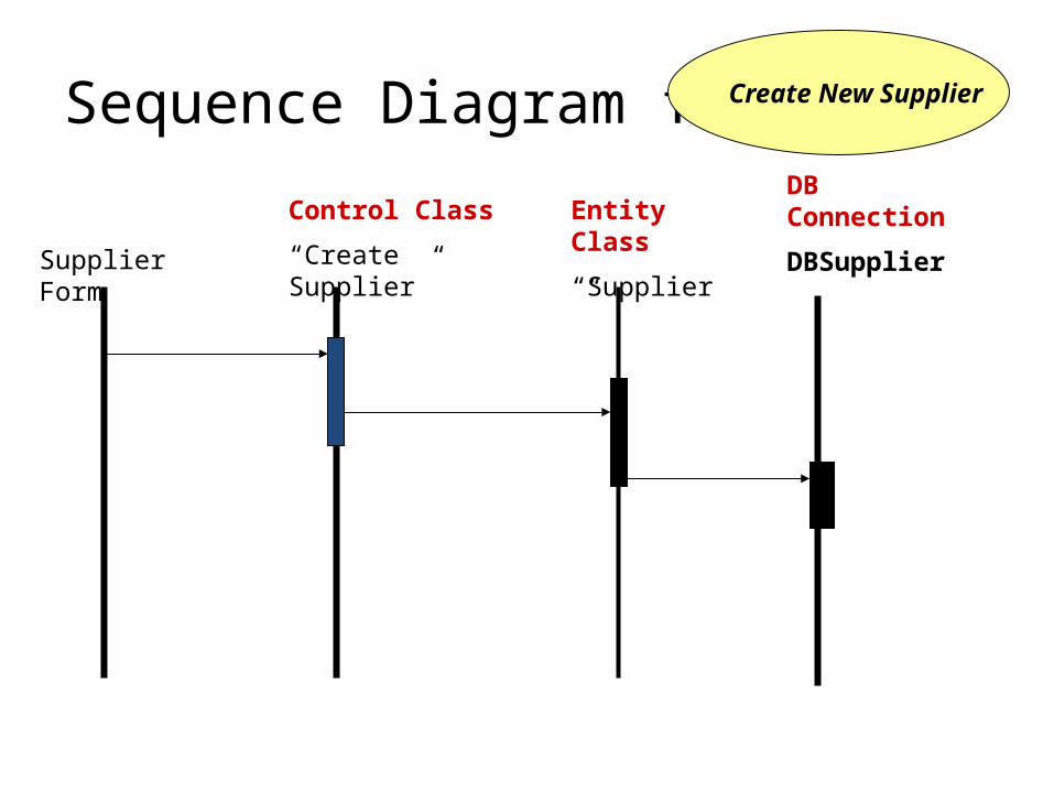
Sequence Diagram for Create New Supplier
Supplier Form
Control Class
“Create Supplier”
Entity Class
“Supplier”
DB Connection
DBSupplier
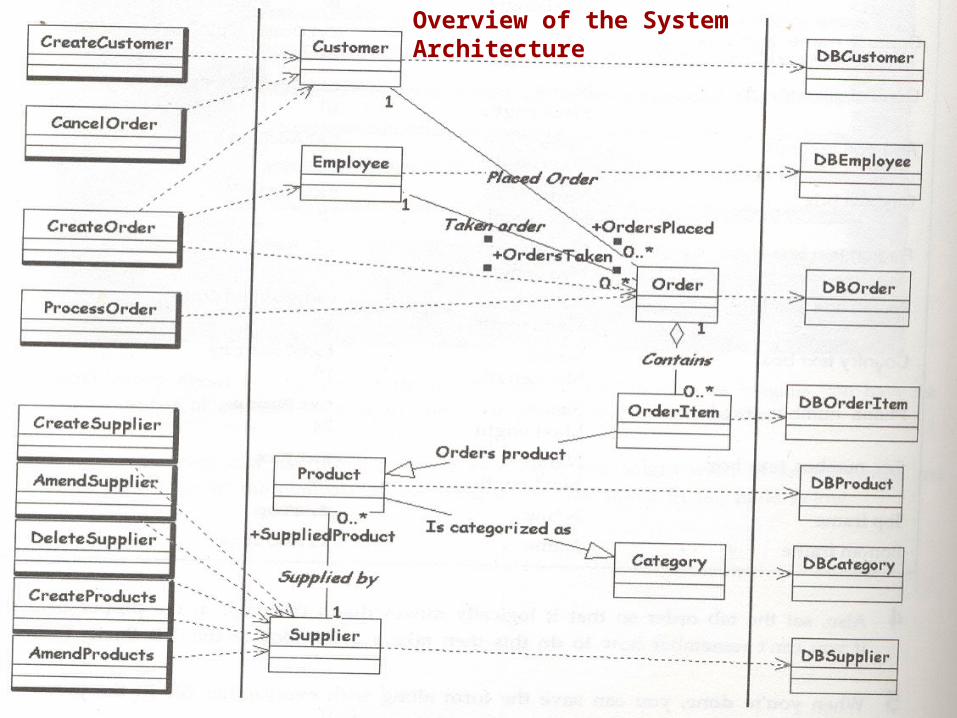
Overview of the System Architecture
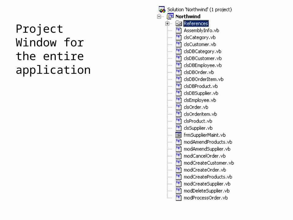
Project Window for the entire application
More Sophisticated Use Cases
Perhaps we could ask the Customer object to:
– Project future sales to this customer. This would involve analysing past sales to identify trends. Implies the need for a “Customer Sales History” class not currently included in the model.
– Collect overdue payments. This would involve generating standard letters to be sent to the customer. Implies collaboration with a “Payment” class (associated with Order or Invoice?) not currently included in the model.
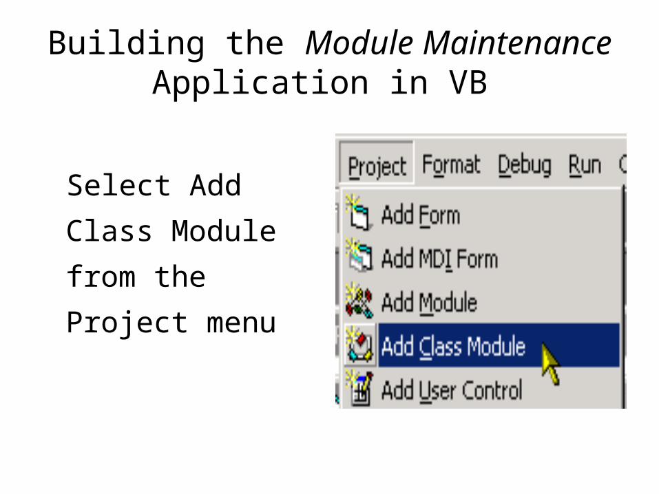
Select Add Class
Module from the
Project menu
Building the Module Maintenance Application in VB
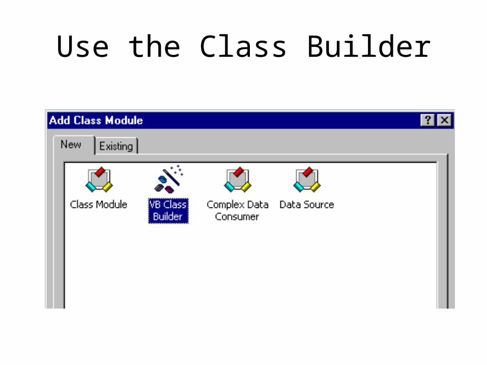
Use the Class Builder
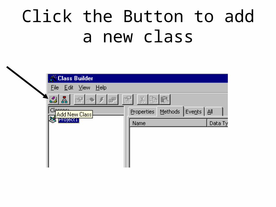
Click the Button to add a new class
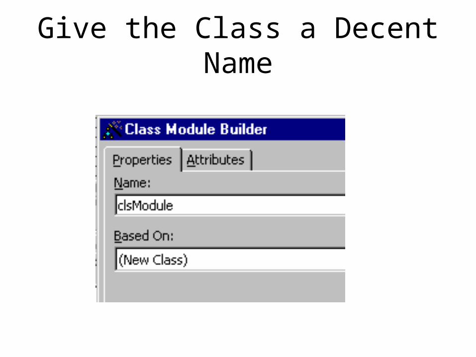
Give the Class a Decent Name
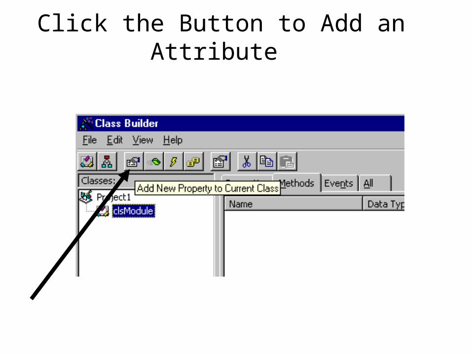
Click the Button to Add an Attribute
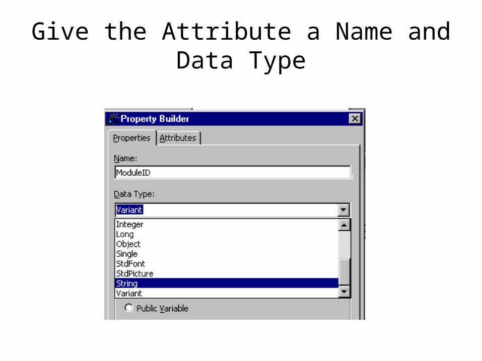
Give the Attribute a Name and Data Type
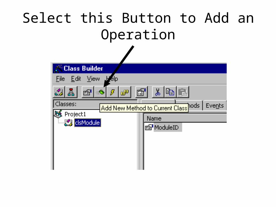
Select this Button to Add an Operation
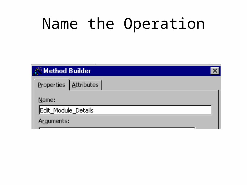
Name the Operation

When we Update the Project the necessary code is generated to implement
the class
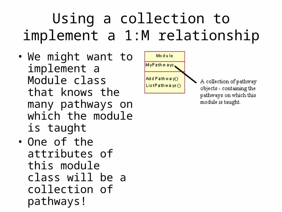
Using a collection to implement a 1:M relationship
• We might want to implement a Module class that knows the many pathways on which the module is taught
• One of the attributes of this module class will be a collection of pathways!
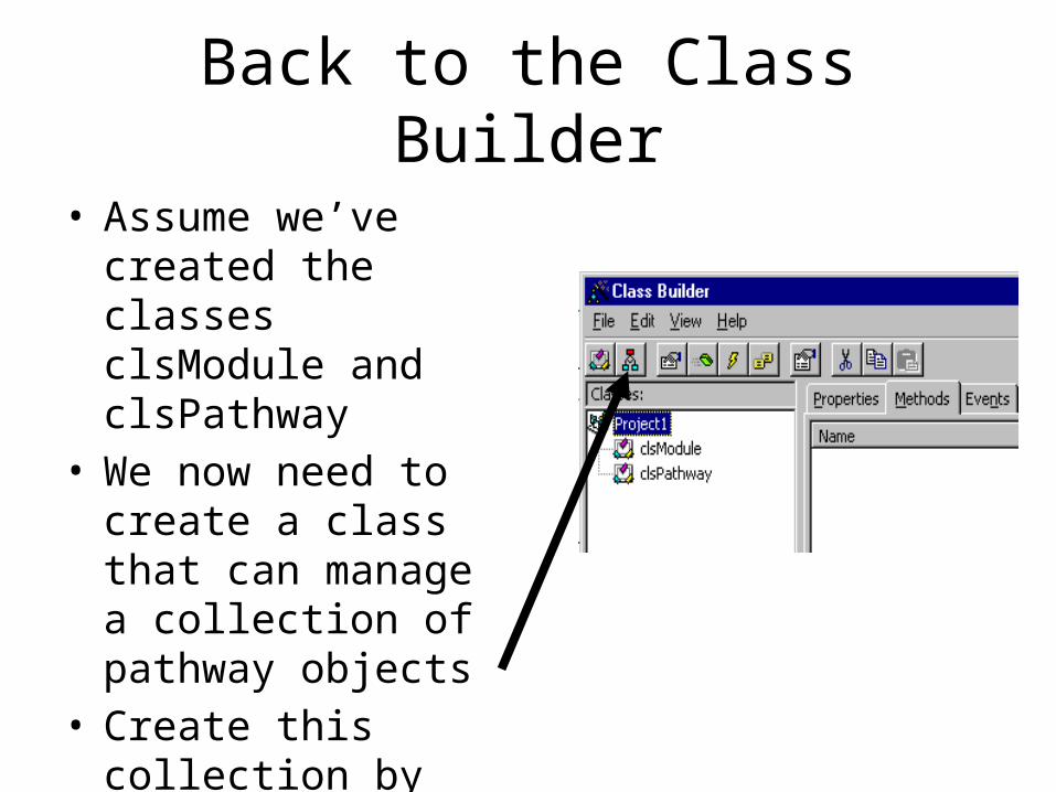
Back to the Class Builder
• Assume we’ve created the classes clsModule and clsPathway
• We now need to create a class that can manage a collection of pathway objects
• Create this collection by clicking this button
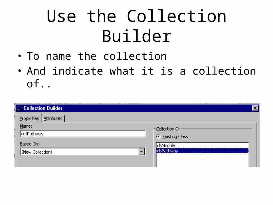
Use the Collection Builder
• To name the collection• And indicate what it is a collection of..
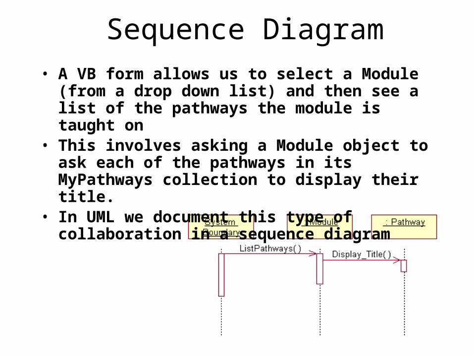
Sequence Diagram• A VB form allows us to select a Module
(from a drop down list) and then see a list of the pathways the module is taught on
• This involves asking a Module object to ask each of the pathways in its MyPathways collection to display their title.
• In UML we document this type of collaboration in a sequence diagram
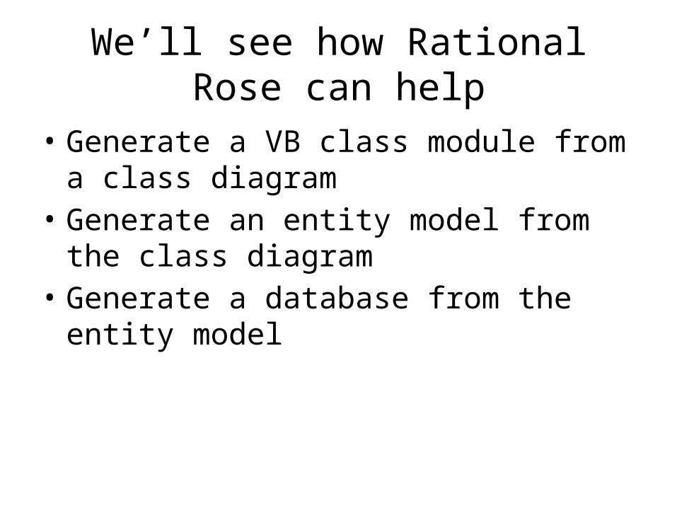
We’ll see how Rational Rose can help
• Generate a VB class module from a class diagram
• Generate an entity model from the class diagram
• Generate a database from the entity model

Create a VB6 Model
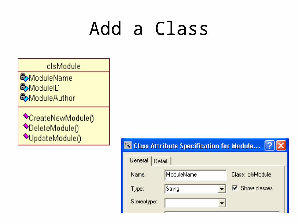
Add a Class

Associate the Model with a VB project
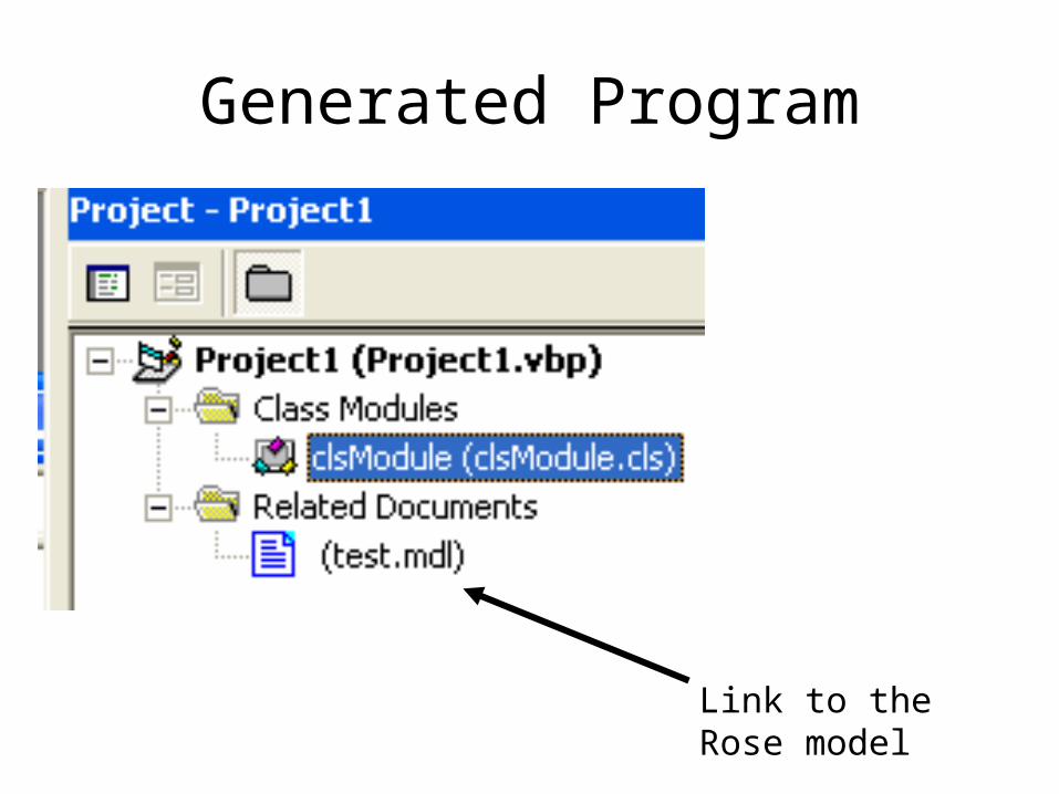
Generated Program
Link to the Rose model
Once this connection has been made…
• We can..– Update the VB project from our model– Update our model from the VB project
• Round-trip engineering
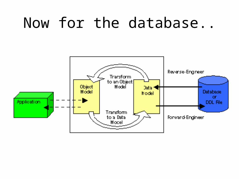
Now for the database..

First tell Rose about the target database
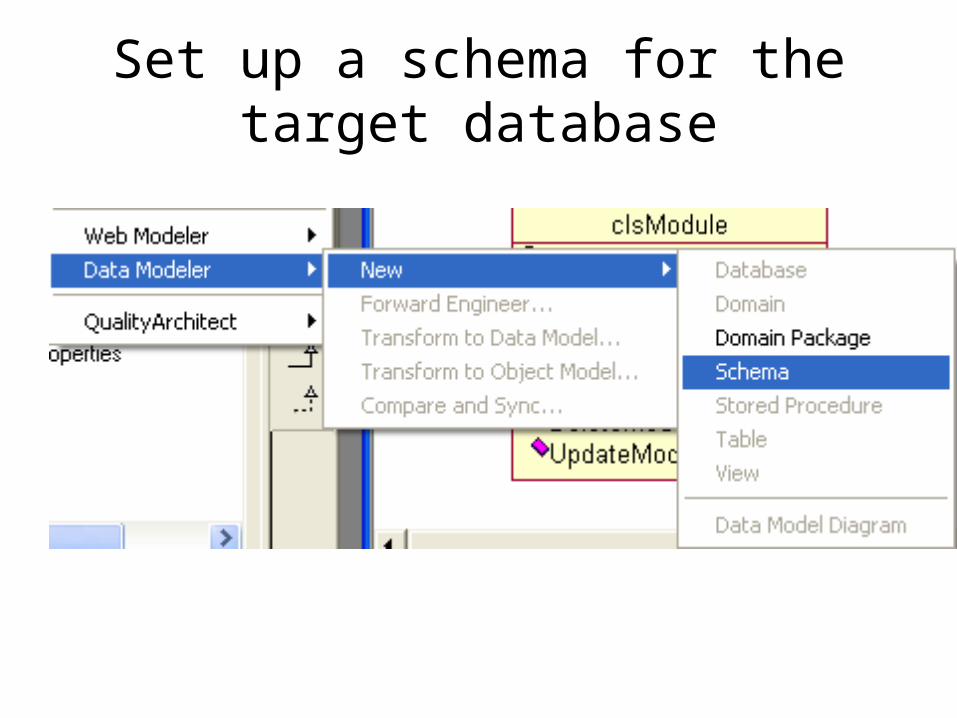
Set up a schema for the target database

Now generate the entity model

Generate the Database from the Schema

Example of Generated SQL