Transactional Analysis 2- Key concepts in transactional analysis

Mark Alan Junho Song
The UML-CAFE:an Environment to Specify and Verify Transactional Systems
Tese de doutorado apresentado ao Curso de
Pos-Graduacao em Ciencia da Computacao da
Universidade Federal de Minas Gerais, como
requisito parcial para a obtencao do grau de
doutor em Ciencia da Computacao.

2
Abstract
Since the last decade the internet has been growing exponentially. As a new computational
infra-structure has became available, new distributed applications which were previously too ex-
pensive or too complex have become common. E-commerce systems, for example, has simplified
the access to goods and services and has revolutionized the economy as a whole.
However, web applications tends to generate complex systems. As new services are created,
the frequency with which errors appear has increased significantly. Besides, ensuring the cor-
rectness of the software design at the earliest stage, a problem known as design validation, is
still a major challenge in any system development process. The most popular methods for design
validation are still the techniques of simulation and testing. Although effective in the early stages
of debugging, their effectiveness drops quickly as the design becomes cleaner.
New approaches can be used in order to improve the quality of the software and to guarantee
the integrity of critical systems. Formal Methods is one such approach. Unfortunately, it is not
a simple task to apply them. Acquiring a level of expertise can represent an obstacle to their
adoption in the software development process.
Usually, to build a complex system the developer abstracts different views of it, builds models
using some notation, verifies that the models satisfy the requirements, and gradually adds details
to transform the models into an implementation. In this context, an unified notation plays an
important role once a symbol can mean different things to different people.
UML-CAFE is an environment that aggregates a model checking approach, an unified mod-
eling language, a set of transformation patterns, and a methodology to specify and automatically
verify transactional applications. Using the proposed environment the designer is able to au-
tomatically identify errors in early stages of the software development and correct them before
they propagate to later stages. Thus, it is possible to generate more reliable applications which is
developed faster and at low costs.

3
Contents
List of Figures 5
List of Tables 7
1 Introduction 81.1 Web Applications . . . . . . . . . . . . . . . . . . . . . . . . . . . . . . . . . .9
1.1.1 Architecture . . . . . . . . . . . . . . . . . . . . . . . . . . . . . . . . .91.2 Formal Methods . . . . . . . . . . . . . . . . . . . . . . . . . . . . . . . . . . .10
1.2.1 Model Checking . . . . . . . . . . . . . . . . . . . . . . . . . . . . . .111.3 Related Work . . . . . . . . . . . . . . . . . . . . . . . . . . . . . . . . . . . .131.4 Contributions . . . . . . . . . . . . . . . . . . . . . . . . . . . . . . . . . . . .161.5 Organization . . . . . . . . . . . . . . . . . . . . . . . . . . . . . . . . . . . . .17
2 Formal Methods 182.1 Introduction . . . . . . . . . . . . . . . . . . . . . . . . . . . . . . . . . . . . .182.2 Model Checking . . . . . . . . . . . . . . . . . . . . . . . . . . . . . . . . . . .19
2.2.1 Modeling Concurrent Systems . . . . . . . . . . . . . . . . . . . . . . .202.2.2 Binary Decision Diagrams . . . . . . . . . . . . . . . . . . . . . . . . .212.2.3 Specifying Properties of Concurrent Systems . . . . . . . . . . . . . . .232.2.4 Temporal Logic . . . . . . . . . . . . . . . . . . . . . . . . . . . . . . .242.2.5 CTL Model Checking . . . . . . . . . . . . . . . . . . . . . . . . . . .27
2.3 The SMV Language . . . . . . . . . . . . . . . . . . . . . . . . . . . . . . . . .292.3.1 Introduction . . . . . . . . . . . . . . . . . . . . . . . . . . . . . . . . .292.3.2 Input File . . . . . . . . . . . . . . . . . . . . . . . . . . . . . . . . . .302.3.3 Reusable Modules and Expressions . . . . . . . . . . . . . . . . . . . .312.3.4 Asynchronous Execution . . . . . . . . . . . . . . . . . . . . . . . . . .332.3.5 Counterexample . . . . . . . . . . . . . . . . . . . . . . . . . . . . . .352.3.6 Summary . . . . . . . . . . . . . . . . . . . . . . . . . . . . . . . . . .35
2.4 A Microwave Example . . . . . . . . . . . . . . . . . . . . . . . . . . . . . . .36
3 Web Based Systems’ Modeling 383.1 Properties . . . . . . . . . . . . . . . . . . . . . . . . . . . . . . . . . . . . . .393.2 The Formal-CAFE Methodology . . . . . . . . . . . . . . . . . . . . . . . . . .40
3.2.1 Conceptual Level . . . . . . . . . . . . . . . . . . . . . . . . . . . . . .413.2.2 Application Level . . . . . . . . . . . . . . . . . . . . . . . . . . . . . .413.2.3 Functional Level . . . . . . . . . . . . . . . . . . . . . . . . . . . . . .423.2.4 Execution or Architectural Level . . . . . . . . . . . . . . . . . . . . . .44
3.3 Formal-CAFE Example . . . . . . . . . . . . . . . . . . . . . . . . . . . . . . .443.3.1 Conceptual Level . . . . . . . . . . . . . . . . . . . . . . . . . . . . . .453.3.2 Application Level . . . . . . . . . . . . . . . . . . . . . . . . . . . . . .503.3.3 Functional Level . . . . . . . . . . . . . . . . . . . . . . . . . . . . . .513.3.4 Execution or Architectural Level . . . . . . . . . . . . . . . . . . . . . .53

4
4 The UML-CAFE Environment 574.1 Preliminaries . . . . . . . . . . . . . . . . . . . . . . . . . . . . . . . . . . . .57
4.1.1 The UML-CAFE Approach . . . . . . . . . . . . . . . . . . . . . . . .584.1.2 The Unified Modeling Language . . . . . . . . . . . . . . . . . . . . . .594.1.3 Transformation Patterns . . . . . . . . . . . . . . . . . . . . . . . . . .60
4.2 The UML-CAFE Methodology . . . . . . . . . . . . . . . . . . . . . . . . . . .624.2.1 Conceptual Phase . . . . . . . . . . . . . . . . . . . . . . . . . . . . . .634.2.2 Application Phase . . . . . . . . . . . . . . . . . . . . . . . . . . . . .684.2.3 Functional Phase . . . . . . . . . . . . . . . . . . . . . . . . . . . . . .724.2.4 Execution Phase . . . . . . . . . . . . . . . . . . . . . . . . . . . . . .78
4.3 The UML-CAFE Translator . . . . . . . . . . . . . . . . . . . . . . . . . . . .794.3.1 Lexical Analyzer . . . . . . . . . . . . . . . . . . . . . . . . . . . . . .804.3.2 Parser . . . . . . . . . . . . . . . . . . . . . . . . . . . . . . . . . . . .83
5 UML-CAFE Case Study 865.1 Conceptual Phase . . . . . . . . . . . . . . . . . . . . . . . . . . . . . . . . . .865.2 Application Phase . . . . . . . . . . . . . . . . . . . . . . . . . . . . . . . . . .915.3 Functional Phase . . . . . . . . . . . . . . . . . . . . . . . . . . . . . . . . . .945.4 Execution Phase . . . . . . . . . . . . . . . . . . . . . . . . . . . . . . . . . . .98
6 Conclusions and Future Work 99
A The SMV Language 102A.1 The input language . . . . . . . . . . . . . . . . . . . . . . . . . . . . . . . . .103
A.1.1 Lexical conventions . . . . . . . . . . . . . . . . . . . . . . . . . . . .103A.1.2 Expressions . . . . . . . . . . . . . . . . . . . . . . . . . . . . . . . . .103A.1.3 Declarations . . . . . . . . . . . . . . . . . . . . . . . . . . . . . . . .105A.1.4 Modules . . . . . . . . . . . . . . . . . . . . . . . . . . . . . . . . . .108A.1.5 Identifiers . . . . . . . . . . . . . . . . . . . . . . . . . . . . . . . . . .110A.1.6 Processes . . . . . . . . . . . . . . . . . . . . . . . . . . . . . . . . . .111A.1.7 Programs . . . . . . . . . . . . . . . . . . . . . . . . . . . . . . . . . .111
A.2 The NuSMV System . . . . . . . . . . . . . . . . . . . . . . . . . . . . . . . .111
B The Unified Modeling Language 114B.1 UML Views . . . . . . . . . . . . . . . . . . . . . . . . . . . . . . . . . . . . .114B.2 Use Case Diagrams . . . . . . . . . . . . . . . . . . . . . . . . . . . . . . . . .115B.3 Class Diagrams . . . . . . . . . . . . . . . . . . . . . . . . . . . . . . . . . . .117B.4 Interaction Diagrams . . . . . . . . . . . . . . . . . . . . . . . . . . . . . . . .119
B.4.1 Sequence Diagrams . . . . . . . . . . . . . . . . . . . . . . . . . . . . .119B.4.2 Collaboration Diagram . . . . . . . . . . . . . . . . . . . . . . . . . . .121
B.5 Statechart Diagram . . . . . . . . . . . . . . . . . . . . . . . . . . . . . . . . .122B.6 Activity Diagram . . . . . . . . . . . . . . . . . . . . . . . . . . . . . . . . . .124B.7 Physical Diagrams . . . . . . . . . . . . . . . . . . . . . . . . . . . . . . . . .126
B.7.1 Deployment Diagram . . . . . . . . . . . . . . . . . . . . . . . . . . . .127B.7.2 Component Diagram . . . . . . . . . . . . . . . . . . . . . . . . . . . .127
C The UML-CAFE Translator 129
Bibliography 152

5
List of Figures
1.1 Three-level architecture of e-commerce server . . . . . . . . . . . . . . . . . . .101.2 The state transition graph and corresponding computation tree. . . . . . . . . . .12
2.1 Example of a transition and its symbolic representation. . . . . . . . . . . . . . .212.2 BDD for(a ∧ b) ∨ (c ∧ d) . . . . . . . . . . . . . . . . . . . . . . . . . . . . .222.3 Binary decision tree and a correspondent BDD for the formula (a ∧ b) ∨
(c ∧ d). . . . . . . . . . . . . . . . . . . . . . . . . . . . . . . . . . . . . . . .232.4 The state transition graph . . . . . . . . . . . . . . . . . . . . . . . . . . . . .242.5 Linear andbranching-time structure of time of temporal logics. . . . . . . . . .252.6 State transition graph and corresponding computation tree. . . . . . . . . . . . .262.7 Basic CTL operators over a computation tree. The ’s’ designates the state taken
as root. The black states represent the states in which propositiong holds. . . . . 282.8 Kripke structure representing a microwave. . . . . . . . . . . . . . . . . . . . .36
3.1 The life cycle graph of product’s item . . . . . . . . . . . . . . . . . . . . . . .423.2 The Second Level of the Methodology . . . . . . . . . . . . . . . . . . . . . . .423.3 The Third Level of the Methodology . . . . . . . . . . . . . . . . . . . . . . . .443.4 An English Auction Site - The life cycle graph of product’s item . . . . . . . . .48
4.1 The UML-CAFE environment . . . . . . . . . . . . . . . . . . . . . . . . . . .584.2 A Pattern Hierarchy . . . . . . . . . . . . . . . . . . . . . . . . . . . . . . . . .624.3 Example of Parameterized Classes . . . . . . . . . . . . . . . . . . . . . . . . .644.4 Example of actor Actions . . . . . . . . . . . . . . . . . . . . . . . . . . . . . .644.5 The Life Cycle of the Negotiated Object . . . . . . . . . . . . . . . . . . . . . .694.6 Property Description . . . . . . . . . . . . . . . . . . . . . . . . . . . . . . . .694.7 UML meta-model - Activity . . . . . . . . . . . . . . . . . . . . . . . . . . . .734.8 UML meta-model - Activity Group . . . . . . . . . . . . . . . . . . . . . . . . .744.9 UML meta-model - Interruptible Activity Region . . . . . . . . . . . . . . . . .744.10 UML meta-model - Isolated Region . . . . . . . . . . . . . . . . . . . . . . . .754.11 Isolation of Conflicting Actions . . . . . . . . . . . . . . . . . . . . . . . . . . .764.12 Physical Diagrams . . . . . . . . . . . . . . . . . . . . . . . . . . . . . . . . .79
5.1 Class Diagram . . . . . . . . . . . . . . . . . . . . . . . . . . . . . . . . . . . .895.2 Administrator Action Diagram . . . . . . . . . . . . . . . . . . . . . . . . . . .905.3 Buyer Group Context Diagram . . . . . . . . . . . . . . . . . . . . . . . . . . .915.4 Manage Adhesion Diagram . . . . . . . . . . . . . . . . . . . . . . . . . . . . .925.5 Property Description . . . . . . . . . . . . . . . . . . . . . . . . . . . . . . . .935.6 Life Cycle of the Negotiated Object . . . . . . . . . . . . . . . . . . . . . . . .945.7 The Manage Proposal and Confirm Adhesion Sequence Diagram . . . . . . . . .965.8 The Manage Proposal and Confirm Adhesion Activity Diagram . . . . . . . . . .965.9 Three Level Architecture . . . . . . . . . . . . . . . . . . . . . . . . . . . . . .985.10 Physical Diagram . . . . . . . . . . . . . . . . . . . . . . . . . . . . . . . . . .98
B.1 Use Case Diagram Example . . . . . . . . . . . . . . . . . . . . . . . . . . . .116

6
B.2 Class Structure . . . . . . . . . . . . . . . . . . . . . . . . . . . . . . . . . . .117B.3 Class Diagram Example . . . . . . . . . . . . . . . . . . . . . . . . . . . . . .117B.4 Generalization . . . . . . . . . . . . . . . . . . . . . . . . . . . . . . . . . . . .118B.5 Sequence Diagram Structure . . . . . . . . . . . . . . . . . . . . . . . . . . . .119B.6 Sequence Diagram Example . . . . . . . . . . . . . . . . . . . . . . . . . . . .120B.7 Sequence Diagram Example . . . . . . . . . . . . . . . . . . . . . . . . . . . .120B.8 Collaboration Diagram Structure . . . . . . . . . . . . . . . . . . . . . . . . . .121B.9 Collaboration Diagram Example . . . . . . . . . . . . . . . . . . . . . . . . . .121B.10 Statechart Diagram Structure . . . . . . . . . . . . . . . . . . . . . . . . . . . .123B.11 Statechart Diagram Conditions . . . . . . . . . . . . . . . . . . . . . . . . . . .123B.12 Statechart Diagram Example . . . . . . . . . . . . . . . . . . . . . . . . . . . .124B.13 Activity Diagram Structure . . . . . . . . . . . . . . . . . . . . . . . . . . . . .125B.14 Activity Diagram . . . . . . . . . . . . . . . . . . . . . . . . . . . . . . . . . .126B.15 Deployment Diagram . . . . . . . . . . . . . . . . . . . . . . . . . . . . . . . .127B.16 Combined Deployment and Component Diagram . . . . . . . . . . . . . . . . .128

7
List of Tables
3.1 Elements ofFormal-CAFE’s methodology . . . . . . . . . . . . . . . . . . . . .403.2 English Auction Events . . . . . . . . . . . . . . . . . . . . . . . . . . . . . . .48
4.1 The UML-CAFE Template . . . . . . . . . . . . . . . . . . . . . . . . . . . . .684.2 Examples of UML-CAFE tokens and their structure . . . . . . . . . . . . . . . .80
5.1 Actors and Attributes . . . . . . . . . . . . . . . . . . . . . . . . . . . . . . . .885.2 Negotiated Object and Attributes . . . . . . . . . . . . . . . . . . . . . . . . . .90

8
Chapter 1
Introduction
Web based systems have changed the way organizations perform their activities. E-commerce
systems, for example, have simplified the access to goods and services and have revolutionized
the economy as a whole. However, web applications tend to generate complex systems - transac-
tional systems involve concurrent operations which demand transactional integrity. Besides, as
new services are created the frequency with which errors appear increase significantly. Guaran-
teeing the correctness of such systems is not an easy task due to the great amount of scenarios
where errors may occur, many of them very subtle. Such task is quite hard and laborious if only
tests and simulations, common techniques of system validation, are used.
New approaches can be used in order to improve the quality of the software and to guarantee
the integrity of critical systems. Formal Methods is one such approach. They consist of the use
of mathematical techniques to assist in the documentation, specification, design, analysis and
certification of computational systems. Model checking [18], a special formal method approach,
is sufficiently interesting and promising since it consists of a robust and efficient technique to
automatically verify the correctness of several system properties, mainly regard to identification
of faults in advance.
The objective of this work is to define and implement an environment which helps the devel-
oper to design and verify transactional systems with model checking support. It can be divided
into four main issues. The first one comprises the study and evaluation of the available ap-
proaches to specify and verify transactional systems, such as web based ones. The second one is
to create a methodology that uses formal-method techniques and an unified modeling language
in the design of these applications. The third one is the implementation of a translator to auto-
matically generate the formal model based on the logical model of the application. The fourth
one is to validate the process through transactional systems such as web applications.
In this thesis we present an environment that uses formal method techniques [31], a standard
notation (the Unified Modeling Language - UML [41]), and a set of transformation patterns [52]
to design and to enable the automatic verification of transactional systems. In the next section

9
it is summarized important concepts about web systems (a class of transactional applications).
Also an introduction to formal methods is presented. After, it is presented the related works and
contributions.
1.1 Web Applications
Web applications [32] is usually described as the use of network resources and information
technology to ease the execution of central processes performed by an organization. It consists
of a set of techniques and computer technologies used to support transactions or make it easier.
An English auction web site and a digital library are traditional examples of web applications.
One of the most promising uses of theses resources and technologies is to support commercial
processes and transactions. One of its advantages is that it allows one-to-one interaction between
customers and vendors through automated and personalized services. Furthermore, it is usually
a better commercialization channel than traditional ones because its costs are lower and it can
reach an enormous potential customer population.
Web servers and traditional WWW servers act in well distinct contexts [22]. There are many
differences between these types of servers. However, they can be differentiated by the additional
functionalities supported and the information stored by Web servers. WWW servers receive
and answer requests, while Web servers keep information transmitted between the user and the
server, and their associated actions. This information is kept for the purpose of transactional
integrity and support to the offered services. The state of the server comprises the user session,
which represents all the interactions that a user makes with the site in one sitting. The following
subsections describe important aspects of Web servers.
1.1.1 Architecture
Components
A Web server [32] can be divided into three integrated components (Figure 1.1):
1. WWW Server: it is the manager of the tasks, being responsible for the interface with the
users (customers), interacting directly with them, receiving the requests, sending them to
transaction server and repassing the results. It provides the interface between the client
access tool (normally abrowser) and the application server.
2. Transaction Server: It processes the requests submitted to the application, such as the
addition/removal of a new product to the shopping cart.
3. Database: It stores all the information, such as the description of the product and the level
of supply. More than a simple repository, it adds several functionalities that allow the
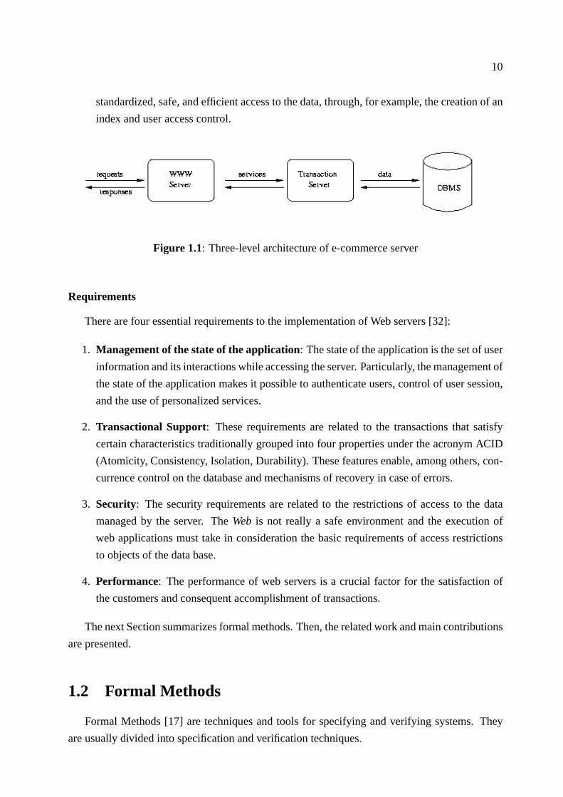
10
standardized, safe, and efficient access to the data, through, for example, the creation of an
index and user access control.
Figure 1.1: Three-level architecture of e-commerce server
Requirements
There are four essential requirements to the implementation of Web servers [32]:
1. Management of the state of the application: The state of the application is the set of user
information and its interactions while accessing the server. Particularly, the management of
the state of the application makes it possible to authenticate users, control of user session,
and the use of personalized services.
2. Transactional Support: These requirements are related to the transactions that satisfy
certain characteristics traditionally grouped into four properties under the acronym ACID
(Atomicity, Consistency, Isolation, Durability). These features enable, among others, con-
currence control on the database and mechanisms of recovery in case of errors.
3. Security: The security requirements are related to the restrictions of access to the data
managed by the server. TheWeb is not really a safe environment and the execution of
web applications must take in consideration the basic requirements of access restrictions
to objects of the data base.
4. Performance: The performance of web servers is a crucial factor for the satisfaction of
the customers and consequent accomplishment of transactions.
The next Section summarizes formal methods. Then, the related work and main contributions
are presented.
1.2 Formal Methods
Formal Methods [17] are techniques and tools for specifying and verifying systems. They
are usually divided into specification and verification techniques.

11
Specification techniques are used to describe a system in order to formalize its requisites and
properties [54, 25]. In general, its product can be usually converted in a system documentation.
Verification techniques go one step beyond [18]. By searching the state space of the model they
are able to identify errors and assist directly in the design of the system. They help designers
to find errors in the system - the application is modeled in a suitable language and properties
about the system are formally described and verified. Two common approaches are the Theorem
Provers and Model Checking.
In the Theorem Prover approach [26], the system is modeled as a set of formulasΦ in a suited
mathematical logic such as first-order logic. The specification is also described as a formulaφ.
The verification is the process of finding a proof forφ such thatΦ ` φ. The proof is usually a
manual or an interactive process.
In the Model Checking approach [18], the system is modeled by transition systems. The
model (M) is finite and the specification is described as a formulaφ in temporal logic. The
model checking process consists of determining whetherM, s |= φ. That is, the model checking
process scans all states ofM that can be reached froms ∈M verifying whetherφ holds or not.
The model checking approach is more restrictive than theorem prover once it deals with finite
systems and it proves the satisfiability ofφ only toM, not to all modelsM, such thatM |= φ.
These aspects make the model checking approach significantly simpler than theorem prover.
However, the model checking verification process is faster and fully automatic. Besides, model
checking is able to present a counter-example whenφ is false - counter-example is a computation
sequence in the model which proves thatM |=/ φ.
Formal methods embrace a variety of approaches that differ considerably in techniques, goals,
claims, and philosophy. The different approaches to formal methods tend to be associated with
different kinds of specification languages [16, 20]. Conversely, it is important to recognize that
different specification languages are often intended for very different purposes and therefore
cannot be compared directly to one another. Failure to appreciate this point is a source of much
misunderstanding. In this work we use model checking, which is an interesting and promising
formal method technique to verify hardware and software systems using temporal logic. The
next subsection describes model checking.
1.2.1 Model Checking
Model checking[18, 39] is a formal verification approach by which a desired behavioral sys-
tem property can be verified over a model through exhaustive enumeration of all states reachable
by the application. The model is a labeled state-transition graph. The labels correspond to the
values of the variables in the program, while the transitions correspond to the passage of time.
The model checking process consists of scanning all states in the model to check if the model
conforms to the properties.

12
Formally, the system is represented as astate-transition graphM - a 4-tuple(S, I, A, δ),
whereS is a set of states,I ⊆ S, is a non-empty subset of initial states,A is a set of actions, and
δ ⊆ S × A × S is a total transition relation. A run ofM is an infinite sequenceρ = s0, s1... of
states such thats0 ∈ I and for alli ∈ N, (si, Ai, si+1) ∈ δ holds for someAi ∈ A.
Properties are conveniently expressed in temporal logic [31]. Temporal logic is a formalism
very useful to describe sequences of transitions between states. One can use temporal logic to
reason about the system in terms of occurrences of events.
There exists several propositions of temporal logic [2]. These logics vary according to the
temporal structure (linear or branching time) and the time characteristic (continuous or discrete).
Temporal linear logics reason about the time as a chain of time instances. Branching-time logics
reason about the time as having many possible futures at a given instance of time.
Time can be continuous or discrete. Time is continuous if between two instances of time there
is always another one, otherwise it is classified as discrete. In our work we used a branching-
time and discrete logic known as Computation Tree Logic (CTL [17]). CTL is derived from state
transition graphs. The graph structure is unwound into an infinite tree rooted at the initial state,
as seen in figure 1.2. Paths in this tree represent all possible computations of the system being
modeled.
Figure 1.2: The state transition graph and corresponding computation tree.
CTL provides operators to be applied over the paths formed by the computation tree. When
these operators are specified in a formula they must appear in pairs and in a specific order:
path quantifierfollowed by temporal operator. A path quantifier defines the scope of the paths
over which a formulaf must hold. There are two path quantifiers:A, meaningall paths; and
E, meaningsomepath. A temporal operator defines the appropriate temporal behavior that is
supposed to happen along a path. The temporal operators are the following:
• F (”in the future”or ”eventually”) - starting from the root,f holds in some state of the path;

13
• G (”globally”or ”always”) - starting from the root,f holds in all states of the path;
• U (”until”) - there is a states in the path where a formulag is satisfied and all predecessor
states ofs satisfiesf .
• X (”next time”) - starting from the root,f holds in the second state of the path.
If f andg are CTL formulas, then¬f , f ∨ g, f ∧ g, AFf , EFf , AGf , EGf , A[fRg], E[fRg],
A[fUg], E[fUg], AXf , EXf are CTL formulas. Some examples of CTL formulas are given
below to illustrate the expressiveness of the logic:
• AG(req → AF ack): it is always the case that if the signalreq is high, then eventually
ack will also be high.
• EF (started∧¬ready): it is possible to get to a state wherestarted holds butready does
not hold.
1.3 Related Work
Although model checking can only deal with finite state systems, it has been successfully
applied to the verification of several large complex systems such as an aircraft controller [12], a
robotic controller [11], a multimedia application [10], and a distributed heterogeneous real-time
system [49].
The key to the efficiency of the algorithms is the use ofbinary decision diagrams[47] to
represent the labeled state-transition graph and to verify if a timing property is true or not. Model
checkers can exhaustively check the state space of systems with more than1030 states in a few
seconds [9].
There are many works related to formal methods and more specifically to formal specification
using symbolic model checking. But, as the ones cited above, they often focus on hardware
verification and protocols, rarely to software applications. For example, [23] describes the
formal verification of SET (Secure Electronic Transaction) protocol. In [4] the authors present
a payment protocol model verification. The article presents a methodology used to perform the
verification using theC-SETprotocol.
Formal analysis and verification of transactional systems have not been studied in detail until
recently. Most work such as [29, 59] concentrates on verifying properties of specific protocols
and do not address how these techniques can assist in the design of new systems. Moreover, these
techniques seem to be less efficient than ours, ranging from theorem proving techniques [4, 29]
which are traditionally less efficient (even though more expressive), to model checking [23, 59].
But even these works tend to be able to verify only smaller systems consuming much higher
resources than our method.

14
According to [5], there is much interest in improving embedded system functionalities, where
security is a critical factor. The use of softwares in this systems enable new functionalities, but
create new possibilities of errors. In this context, formal methods might be good alternatives to
avoid them. But even the authors mentioned that formal methods are rarely adopted because of
their complexity.
According to [24], although formal specification and verification methods offer practitioners
some significant advantages over the current state-of-the-practice, they have not been widely
adopted. Despite the automation, one of the major causes is that the users of finite-state tools
still must be able to specify the system requirements in the specification language of the tool.
Consider, for example, the following requirement for an elevator: Between the time an el-
evator is called at a floor and the time it opens its door at that floor, the elevator can arrive at
that floor at most twice. To verify this property with a linear temporal logic (LTL [18]) model
checker, a developer would have to translate this informal requirement into the following LTL
formula:
2((call∧3open) → ((¬atfloor∧¬open)∪ (open∨((atfloor∧¬open)∪ (open∨((¬atfloor∧¬open)∪ (open ∨ ((atfloor ∧ ¬open)∪ (open ∨ (¬atfloor ∪ open)))))))))).
Not only is this formula difficult to read and understand, but it is even more difficult to
write correctly without the knowledge in the syntax of the specification language. In [24] it has
been proposed an abstraction, named specification pattern, which is a generalized description
of a commonly occurring requirement on the permissible state/event sequences of a finite-state
model, such as:
• CTL - S precedes P:
1. Globally: E[¬S ∧ (P ∨ ¬S))]
2. Before R:¬E[(¬S ∨ ¬R) ∧ (P ∨ ¬S ∨ ¬R ∨ EF (R))]
• LTL - S precedes P:
1. Globally: (P → ¬P ∧ (S ∨ ¬P ))
2. Before R:(R → (¬P ∧ (S ∨R))]
As noted, the abstraction is intended to capture experience of formal specifiers. But, it is
still necessary to specify properties using some temporal logic. Even with significant expertise,
dealing with the complexity of such a specification can be daunting.
In many software development phases, such as design and coding, complexity is addressed
by the definition and use of abstractions. For complex specification problems, abstraction is just
as important. In our work we define a set of transformation patterns so that it can be applied to
model checking of transactional systems: the designer describes the elements of the application
using a modeling language (UML) as defined in the UML-CAFE methodology, and the elements

15
of the model are automatically projected, through the UML-CAFE translator, into the formal
model to be verified.
The UML-CAFE Translator is a parser which takes UML specifications as it’s input and
produces a corresponding parse tree for the formal model to be verified. It reads the source pro-
gram (UML specifications), discovers its structure and processes it generating the target program
(formal model). Lex and Yacc [37] has been used to implement the UML-CAFE translator.
Lex helps write programs whose control flow is directed by instances of regular expressions
in the input stream. It is well suited for editor-script type transformations and for segmenting
input in preparation for a parsing routine.
Yacc provides a general tool for describing the input to a computer program. The Yacc user
specifies the structures of his input, together with code to be invoked as each such structure is
recognized. Yacc turns such a specification into a subroutine that handles the input process;
frequently, it is convenient and appropriate to have most of the flow of control in the user’s
application handled by this subroutine.
We have decided to used Lex and Yacc in the implementation of the UML-CAFE translator
once we were familiarized with such tools. But any other one could have been used. TXL [56],
for example, is a programming language designed to support computer software analysis and
source transformation tasks. Divide into a description of the structures to be transformed (BNF
grammar) and a set of structural transformation rules it could be used as a parser generator.
The work described in [6] presents practical questions that invalidate myths related to formal
methods, and elaborate some conclusions that serve as motivation for our work:
• An important question is how to make it easy the adoption of formal methods in software
development process.
• Formal methods are not a panacea, they are an interesting approach that, as others, can
help the development of correct systems.
Formal methods techniques provide many benefits in the system development process. The
formal specification acts as a mechanism of fails prevention, through a precise specification
and without ambiguity in the system’s functional requirements. The initial stages of the system
development (documentation, requirements specification, and design) are considered the most
critical, whereas the incidence of fails is normally observed. It is a consensus that the fails
introduced in the earliest stages of the system development’s lifecycle are more difficult and
expensive to be detected and removed.
It is claimed [40] that the use of formal methods can be eased, in the software development
process, if the designer can use tools that reduce, among other things:
• the amount of time demanded to develop the system, and

16
• the gap between the modeling language used to describe the logical model of the applica-
tion, and the formal language used to generate the formal model to be verified.
There are some work in that direction [57], but they are focused on verifying code. The
Bandera Environment [21] and VeriSoft Tool [35] are examples. The first integrates existing
programming language processing techniques to provide automated support for the extraction of
finite-state models that are suitable for verification from Java source code. The second is a tool
to test software applications developed in C and C++. Note that they do not guide the designer
in the software development process - the code for the application must be available at all time.
Most software engineers adopts a high level modeling language, such as UML, to general-
purpose software design. UML-CAFE is an environment developed to help the designer in the
specification and verification of transactional systems. It is based on a methodology to guide the
design, an unified modeling language, and a model checking approach to verify properties about
the system being developed.
Nevertheless, there are applications that can not be fully represented by UML such as em-
bedded, real-time and e-business - they tend to be highly event-driven, concurrent, and often
distributed. In order to solve this problem, there are other modeling languages, such as UML-
RT [28] and ROOM [50].
Our experience pointed out that these languages are focused in real-time systems and do
not fit transactional properties. To describe them correctly we propose extensions in the UML.
Actually, we define a methodology to produce a more accurate software design that aggregates
concepts of formal methods, transformation patterns and UML.
1.4 Contributions
Through our work it has become evident that there are few approaches to design transactional
systems with model checking support. Following are the main contributions of this work:
• it develops an environment to design more reliable transactional systems, such as Web
based applications (we propose a methodology to guide the designer in the development
of such systems);
• it defines UML extensions in order to represent new features such as concurrency and
synchronization;
• it describes how to translate an UML model into a formal verification model;
• it implements a tool which translates UML specifications into a formal model to be verified,
and also
• provides the opportunity to extend the work to other application areas.

17
1.5 Organization
This Chapter summarized basic concepts involved in our work. Chapter 2 describes in detail
formal methods. Chapter 3 explains important concepts of Web based system’s modeling (the
focus of our work) and presentsFormal-CAFE, the formal methodology which is the base of the
UML-CAFE Methodology. Chapter 4 describes our Environment - it presents the UML-CAFE
Methodology and the transformation patterns used in our work. Chapter 5 shows a case study
to validate the UML-CAFE Environment. Chapter 6 presents our conclusions and future work.
For sake of completeness some appendices are also presented: Appendix A describes the SMV
language, Appendix B describes the Unified Modeling Language, and Appendix C describes the
UML-CAFE translator.

18
Chapter 2
Formal Methods
This Chapter presents a background on Formal Methods and describes some scenarios where
this technique is successfully employed for developing correct and robust systems.
2.1 Introduction
Formal Methods [31] are techniques and tools fully-based on mathematical background for
specifying and verifying systems. They are usually divided into specification and verification
techniques.
Specification techniques are used to describe a system in order to formalize its requisites and
properties. In general, its product can be usually converted in a system documentation. Examples
of specification techniques/tools are Z [54] and VDM [25]. Verification techniques [18] go one
step beyond. They help designers to find errors in the system - the application is modeled in
a suitable language and properties about the system are formally described and verified. The
verification techniques and tools are usually split into Theorem Provers and Model Checking.
In the Theorem Prover approach [26], the system is modeled as a set of formulasΦ in a suited
mathematical logic such as first-order logic. The specification is also described as a formulaφ.
Verification is the process of finding a sequenceφ1, ..., φn such thatφn = φ and each formulaΦi
is either an axiom or a derivation ofφi−1 through inferences rules.
In the Model Checking approach [18], the system is modeled by transition systems. The
model (M) is finite and the specification is described as a formulaφ in temporal logic. The
model checking process consists of determining whetherM, s |= φ. That is, the model checking
process scans all states ofM that can be reached froms ∈M verifying whetherφ holds or not.
The model checking approach is more restrictive than theorem prover once it deals with finite
systems and it proves the satisfiability ofφ only toM, not to all modelsM, such thatM |= φ.
These aspects make model checking approach significantly simpler than theorem prover.

19
However, the model checking verification process is fast and fully automatic. Besides, model
checking is able to present a counter-example, whenφ is falsified. Counter-example is a compu-
tation sequence in the model which proves thatM |=/ φ.
2.2 Model Checking
Model checkingis a formal verification approach by which a desired behavioral property of
a system can be verified over a model through exhaustive enumeration of all the states reachable
by the application and the behaviors that traverse through them.
The system being verified is represented as astate-transition graph(the model) and theprop-
erties (the behaviors) are described as formulas in some temporal logic. Formally, the model
is a labeled state-transition graph. The labels correspond to the values of the variables in the
program, while the transitions correspond to the passage of time in the model.
The model checking process consists in searching through all states of the model to check if
the model satisfies the properties.
Model checking technique has some different variations.Temporal logicmodel checking [16]
represent the system as finite state transition graph and a temporal logic [36] is used to specify
properties about the system. Efficient algorithms search the state space to check if the model
satisfies the properties. Inautomataapproach, the system and the properties are represented as
automata. Then, the system is compared to the properties to determine if they hold to the system.
This comparison is accomplished by techniques such as language inclusion, refinement order-
ings, and observational equivalence [17]. Another approach isinteger linear programming[20].
The system and the properties are modeled as a linear inequality system. The inequalities rep-
resent the necessary conditions for an execution of the system such that violates the properties.
The inequality system is applied to an ILP method. If an integral solution is found then the nec-
essary conditions for the violation of the properties hold. Hence, the system does not model the
properties.
Applying model checking to a design consists of several tasks, that can be classified in three
main steps, as follows:
Modeling: consists of converting a design into a formalism accepted by a model checking tool.
Property Specification: before verification, it is necessary to state the properties that the design
must satisfy. The specification is usually given in some logical formalism. It is common
to usetemporal logicwhich can assert how the behavior of the system evolves over time.
An important issue in specification iscompleteness. Model Checking provides means for
checking that a model of the design satisfies a given specification, but it is impossible to
determine whether the given specification covers all the properties that the system should

20
satisfy. This problem illustrates how important a methodology is to conceive a better spec-
ification in terms ofcompleteness.
Verification: execution of the verifying process in order to determine if the properties hold for
the model. In case of a negative result, it is provided an error trace. This can be used as
a counter-example for the checked property and can help the designer in tracking down
where the error occurred.
2.2.1 Modeling Concurrent Systems
In order to model the system, a type of state transition graph called aKripke structure[18]
is used. A Kripke structure consists of a set of states, a set of transitions between states, and a
function that labels each state with a set of properties that are true in this state. Paths in a Kripke
structure model computations of the system.
A state is a snapshot of the system that captures the values of the variables at a particular
instant of time. An assignment of values to all the variables defines a state in the graph. For
example, if the model has three boolean variablesa, b, andc, then (a = 1, b = 1, c = 1), (a = 0, b
= 0, c =1), and (a = 1, b = 0, c = 0) are examples of possible states. Thesymbolic representations
of these states are(a, b, c), (a, b, c), and(a, b, c), respectively, wherea means that the variable is
true in the state anda means that the variable is false. Boolean formulas over variables of the
model can be true or false in a given state. Note that the value of a boolean formula in a state is
obtained by substituting the values of the variables into the formula for that state. For example,
the formulaa ∨ c is true in all the three states discussed above.
The graph representation can be a direct consequence of this observation. One can use a
boolean formula to denote the set of states in which that formula is satisfied. For example, the
formula true represents the set of all states, the formulafalserepresents the empty set with no
states, and the formulaa ∨ c represents the set of states in whicha or c are true. Notice that
individual states can be represented by a formula with exactly one proposition for each variable
in the system. For instance, the states = (a, b, c) is represented by the formulaa ∧ ¬b ∧ c. We
say thata ∧ ¬b ∧ c is the formula associated with the states.
Transitions can also be represented by boolean formulas. A transitions → t is represented
by using two distinct sets of variables, one set for the current states and another set for the next
statet. Each variable in the set of variables for the next state corresponds to exactly one variable
in the set of variables for the current state. For instance, if the variables for the current state are
a, b, andc, then the variables for the next state are labeleda′, b′, andc′. Let fs be the formula
associated with the states andft with the statet. Then, the transitions → t is represented by
fs ∧ ft. The meaning of this formula is the following: there exists a transition from states to
statet if and only if the substitution of the variable values fors in the current state and those of

21
t in the next state yieldstrue. For example, a transition (Figure 2.1) from the state(a, b, c) to the
state(a, b, c) is represented by the formula¬a ∧ ¬b ∧ ¬c ∧ ¬a′ ∧ b′ ∧ ¬c′.
Figure 2.1: Example of a transition and its symbolic representation.
As boolean formulas can represent sets of states, they can also represent sets of transitions.
Because symbols are used to represent states and transitions, algorithms that use this method are
called symbolic algorithms and the methodSymbolic Model Checking[18].
Symbolic model checking have been successfully applied to the verification of several large
complex systems such as an aircraft controller [12], a robotics controller [11], and a distributed
heterogeneous real-time system [49]. They can exhaustively check the state space of systems
with more than1030 states in a few seconds [9, 12, 8]. The key to the efficiency of the algorithms
is the use ofbinary decision diagrams[7] to represent the labeled state-transition graph and to
verify if a timing property is true or not.
The transition relation of the model is a disjunction of all particular transitions in the graph.
The clustering of transitions happens automatically when boolean formulas are implemented
using BDDs. This occurs because bdds are canonicals: given a fixed variable ordering, a boolean
formula is represented by a unique BDD. Therefore, the order in which the transition relation is
constructed does not affect the final result i.e., the canonical property guarantees that the same
transitions will be clustered according to the formulas that represent them. Symbolic model
checking takes advantage of this fact by grouping sets of transitions into a single formula which
simplifies traversing the graph. This technique is one of the main reasons for the efficiency of
symbolic algorithms. The next subsection describes binary decision diagrams.
2.2.2 Binary Decision Diagrams
Binary decision diagrams (BDDs) are a canonical representation for boolean formulas [7].
A BDD is obtained from a binary decision tree by merging identical subtrees and eliminating
nodes with identical left and right siblings. The resulting structure is a directed acyclic graph
rather than a tree which allows nodes and substructures to be shared.
The internal vertices are labeled with boolean variables. Leaves are labeled with 0 and 1.
Canonicity is ensured placing a strict total order on the variables as one traverses a path from
“root” to “leaf”. The edges are labeled with 0 or 1. For every truth assignment there is a corre-
sponding path in the BDD such that at vertexx, the edge labeled 1 is taken if the assignment sets
x to 1; otherwise, the edge labeled 0 is taken.

22
If the path end in the “leaf” labeled 0 then the formula will not be satisfied, conversely, if
it end in the “leaf” labeled 1 then the formula will be satisfied - the assignment made to each
variable satisfies the formula. Figure 2.2 illustrates the BDD for the boolean formula(a ∧ b) ∨(c ∧ d).
Figure 2.2: BDD for (a ∧ b) ∨ (c ∧ d)
Formally, a BDD is a directed acyclic graph with two kinds of vertex: non-terminal and ter-
minal. Each non-terminal vertexv is labeled byvar(v), a distinct variable of the corresponding
boolean formula. Eachv has at least one incident arc (except the root vertex). Eachv also
has two outgoing arcs directed toward two children:left(v), corresponding to the case where
var(v) = 0, andright(v), corresponding to the case wherevar(v) = 1.
A BDD has two terminal vertices labeled by 0 and 1, representing the truth value of the
formula, respectively,falseandtrue. For every truth assignment to the boolean variables of the
formula, there is a corresponding path in the BDD from root to a terminal vertex. Figure 2.3
illustrates a BDD for the boolean formula(a ∧ b) ∨ (c ∧ d) compared to a Binary Decision Tree
for this same formula.
BDDs are the main data structure of Symbolic Model Checking. They are an efficient way
to represent boolean formulas. Often, they provide a much more concise representation than
traditional representations, such as conjunctive normal forms and disjunctive normal forms.
BDDs are a canonical representation for boolean formulas. This means that two boolean
formulas are logically equivalent if and only if its BDDs are isomorphic. This property simplifies
the execution of frequent operations, like checking the equivalence of two formulas or deciding
if a formula is satisfiable or not.
However, bdd has drawbacks. The most significant is related to the order in which variables
appear. Given a boolean formula, the size of the corresponding BDD is highly dependent on the
variable ordering. The BDD can grow from linear to exponential to the number of variables of
the formula. In addition, the problem of choosing an variable order that minimize the BDD size
is co NP-complete [7]. Despite the existence of heuristics to automatic ordering the variables,
sometimes is necessary to order them manually.

23
Binary decision tree BDD
Figure 2.3:Binary decision tree and a correspondent BDD for the formula (a∧ b)∨ (c∧d).
2.2.3 Specifying Properties of Concurrent Systems
In order to write specifications that describe properties of concurrent systems we need to
define a set ofatomic propositions AP. An atomic proposition is an expression that has the form
v op dwherev ∈ V - the set of all variables in the system,d ∈ D - the domain of interpretation,
andop is any relational operator. Now, we can formally define aKripke structure MoverAP as
a four tupleM = (S, S0, R, L) where:
1. S is a finite set of states.
2. S0 ⊆ S is the set of initial states.
3. R ⊆ S × S is a transition relation that must be total.
4. L : 2AP is a function that labels each state with the set of atomic propositions true in that
state.
To illustrate the notions defined we consider the simple system, whereV = {x, y}, D =
{0, 1} andS0(x, y) ≡ (x = 0) ∧ (y = 1). The only possible transition isx = y represented by
the formulaR(x, y, x′, y′) ≡ (x′ = y) ∧ (y′ = y).
The kripke structureM = (S, S0, R, L) extracted from these formula is:
• S = {(0, 0), (0, 1), (1, 0), (1, 1)}.
• S0 = {(0, 1)}.
• R = {[(0, 0), (0, 0)], [(0, 1), (1, 1)], [(1, 0), (0, 0)], [(1, 1), (1, 1)]}.

24
• L((0, 0)) = {x = 0, y = 0}, L((0, 1)) = {x = 0, y = 1}, L((1, 0)) = {x = 1, y = 0},andL((1, 1)) = {x = 1, y = 1}.
procedure exemplo;
var
x := 0;
y := 1;
begin
while (true) x = y;
end
The Figure 2.4 graphically shows the kripke structureM . As one can note the only path
which starts in the initial state is(0, 1)(1, 1)(1, 1)...(1, 1). This is the only computation of the
system.
Figure 2.4: The state transition graph
2.2.4 Temporal Logic
Temporal logic is a formalism very useful to describe sequences of transitions between states.
With temporal logic we are able to reason about the system in terms of occurrences of events.
For example, we can reason if a given event willeventuallyoccur or ifalwaysoccur.

25
There exists several propositions of temporal logic [2]. These logics vary according temporal
structure (linear or branching-time) and time characteristic (continuousor discrete). Temporal
linear logics reason about the time as a chain of time instances. Branching-time logics reason
about the time as having many possible futures at a given instance of time as shown in the
Figure 2.5. Time is continuous if between two instances of time there is always another instance.
Time is discrete if between two instances of time a third one can not be determined. In our work
we used a branching-time and discrete logic known as Computation Tree Logic (CTL).
Figure 2.5: Linear andbranching-time structure of time of temporal logics.
The Computation Tree Logic - CTL
Computation tree logic, is the logic used to express properties that will be verified by the
model checker.Computation treesare derived from state transition graphs. The graph structure
is unwound into an infinite tree rooted at the initial state, as seen in figure 2.6. Paths in this tree
represent all possible computations of the program being modeled.
CTL provides operators to be applied over the paths formed by the computation tree. When
these operators are specified in a formula they must appear in pair and in this order:path quan-
tifier followed bytemporal operator. A path quantifier defines the scope of the paths over which
a formulaf must hold. There are two path quantifiers:A, meaningall paths; andE, meaning
somepath. A temporal operator defines the appropriate temporal behavior that is supposed to
happen along a path relating a formulaf . The temporal operators are the following:
• F (”in the future”or ”eventually”) - starting from the root,f holds in some state of the path;
• G (”globally”or ”always”) - starting from the root,f holds in all states of the path;

26
Figure 2.6: State transition graph and corresponding computation tree.
• U (”until”) - there is a states in the path where a formulag is satisfied and all predecessor
states ofs satisfiesf .
• X (”next time”) - starting from the root,f holds in the second state of the path.
A well formed CTL formula is defined as follows:
1. If p ∈ AP , thenp is a CTL formula, such thatAP is the set of atomic propositions;
2. If f andg are CTL formulas, then¬f , f ∨ g, f ∧ g, AFf , EFf , AGf , EGf , A[fRg],
E[fRg], A[fUg], E[fUg], AXf , EXf , are CTL formulas.
Considering the Kripke modelM = (S, ρ, L)1, we denote thatM satisfies a CTL formulaf
from a states ∈ S as
M, s |= f
Let f andg be CTL formulas, the satisfaction relation|= is defined inductively as follows:
M, s |= p ⇔ p ∈ L(s)
M, s |= ¬f ⇔ M, s 6|= f
M, s |= f ∨ g ⇔ M, s |= f or M, s |= g
M, s |= f ∧ g ⇔ M, s |= f andM, s |= g
M, s |= AFf ⇔ for all paths froms, sk ∈ S is reachable andsk |= f
M, s |= EFf ⇔ for some path froms, sk ∈ S is reachable andsk |= f
M, s |= AGf ⇔ for all pathsπ = s0s1s2 . . . , si |= f , for all i ≥ 0, ands0 = s
1We are not concerning at this momentS0 - the set of initial states.

27
M, s |= EGf ⇔ for some pathπ = s0s1s2 . . . , si |= f , for all i ≥ 0, ands0 = s
M, s |= AXf ⇔ for all sx such thatρ(s, sk) is defined,sk |= f
M, s |= A[fUg] ⇔ for all pathsπ = s0s1s2 . . . sk . . . , si |= f, 0 ≤ i < k andsk |= g
M, s |= E[fUg] ⇔ for some pathπ = s0s1s2 . . . sk . . . , si |= f, 0 ≤ i < k andsk |= g
Despite all combinations we can get with path quantifiers and temporal operators presented
above, we can express any CTL formula using∨, ¬, EX, EU, EG [18]:
• AF f = ¬ EG¬f
• AG f = ¬ EF¬f
• AX f = ¬ EX ¬f
• A[f U g ] ≡ ¬ E[¬g U (¬f ∧ ¬g)] ∧¬ EG¬g
• EFf = E[> U f ]
Figure 2.7 presents the computation of the most frequently used CTL operators. Some typical
examples of CTL formulas relating to concurrent reactive systems are presented below:
• EF(started∧¬ready) - it is possible to get to a state wherestarted holds butready does
not hold.
• AG(req → AF (ack)) - it is always the case that if the signalreq is high, then eventually
ack will also be high.
• A[greenLight U armMoves] - it is always the case that the robot’s arm moves after the
green light is on;
2.2.5 CTL Model Checking
CTL model checking consists of searching for Kripke model’s states with labelf , wheref is
a CTL formula. The set of states labeled tof are the ones that satisfies the formula. Formally, let
f be a CTL formula andlabel(s) be the set of sub formulas off that are true ins ∈ S. The CTL
model checking problem is related to determining the setS = {s | M, s |= f → f ∈ label(s)}.The model check process has two phases: translation and labeling. The translation phase
consists of rewriting a CTL formula in terms of¬, ∨, EX, EG, and EU. The labeling is a process
of i steps, wherei is the number of sub formulas off . In eachith step, thei − 1 nested CTL
operator (sub formula) labels a state if the sub formula is true in that state.
The labeling process observe the following rules:
• labels to p, if p ∈ AP andp ∈ L(s);

28
Figure 2.7: Basic CTL operators over a computation tree. The ’s’ designates the state taken as
root. The black states represent the states in which propositiong holds.
• labels to¬f1, if s is not labeled withf1
• labels to f1 ∨ f2 if s is labeled withf1 or with f2;
• labels to EXf , if t is labeled withf andR(s, t);
• labels to E[f1 U f2]
1. if s is labeled withf2;
2. repeat backward froms: label t to E[f1 U f2] if t is labeled withf1 and exists a
stateu labeled with E[f1 U f2], such thatR(t, u);
• labels to EG[f ]
1. label all states to EG[f ];
2. delete EG[f ] from any states in which if s is not labeled withf ;
3. delete EG[f ] from any states if does not exist a statet labeled with EG[f ], such that
R(s, t).
Using a more efficient EG labeling algorithm that take into consideration the decomposition
of graph into ”nontrivial strongly connected components” [1], the complexity of the labeling
algorithm isO(i.(V + E)), wherei is the number of connectives of the CTL formula,V is the
number of states, andE is the number of transitions.

29
2.3 The SMV Language
In this section we briefly describe the SMV system [38] which we use to construct and verify
formal models of e-commerce systems. A complete description can be found in Appendix A.
2.3.1 Introduction
The SMV system is a tool for checking finite state systems against specifications in the tem-
poral logic CTL. The input language of SMV is designed to allow the description of finite state
systems that range from completely synchronous to completely asynchronous, and from the de-
tailed to the abstract. One can readily specify a system as a synchronous machine, or as an
asynchronous network of abstract, nondeterministic processes. The language provides for mod-
ular hierarchical descriptions, and for the definition of reusable components. Since it is intended
to describe finite state machines, the only basic data types in the language are finite scalar types.
Static, structured data types can also be constructed.
The logic CTL allows a rich class of temporal properties, including safety, liveness, fairness
and deadlock freedom, to be specified in a concise syntax. SMV uses the OBDD-based symbolic
model checking algorithm to efficiently determine whether specifications expressed in CTL are
satisfied.
The primary purpose of the SMV input language is to provide a symbolic description of the
transition relation of a finite Kripke structure. Any propositional formula can be used to describe
this relation. This provides a great deal of flexibility, and at the same time a certain danger of
inconsistency. For example, the presence of a logical contradiction can result in a deadlock - a
state or states with no successor. This can make some specifications vacuously true, and makes
the description unimplementable.
While the model checking process can be used to check for deadlocks, it is best to avoid the
problem when possible by using a restricted description style. The SMV system supports this by
providing a parallel-assignment syntax. The semantics of assignment in SMV is similar to that
of single assignment data flow languages.
A program can be viewed as a system of simultaneous equations, whose solutions determine
the next state. By checking programs for multiple assignments to the same variable, circular
dependencies, and type errors, the compiler insures that a program using only the assignment
mechanism is implementable. Consequently, this fragment of the language can be viewed as a
hardware description language, or a programming language.
The SMV system is by no means the last word on symbolic model checking techniques,
nor is it intended to be a complete hardware description language. It is simply an experimental
tool for exploring the possible applications of symbolic model checking to hardware verification.
Following, we present a few simple examples that illustrate basic concepts of SMV.

30
2.3.2 Input File
Consider the following example:
MODULE main
VAR
request : boolean;
state : { ready, busy };
ASSIGN
init(state) := ready;
next(state) := case
state = ready & request : busy;
1 : { ready, busy };
esac;
SPEC AG(request -> AF state = busy)
The input file describes both the model and the specification. The model is a Kripke structure,
whose state is defined by a collection of state variables, which may be of Boolean or scalar type.
The variable request is declared to be a Boolean in the above program, while the variable state
is a scalar, which can take on the symbolic values ready or busy. The value of a scalar variable
is encoded by the compiler using a collection of Boolean variables, so that the transition relation
may be represented by an BDD. This encoding is invisible to the user, however.
The transition relation of the Kripke structure, and its initial state (or states), are determined
by a collection of parallel assignments (a system of simultaneous equations), which are intro-
duced by the keyword ASSIGN.
The Case Expression
In the above program, the initial value of the variable state is set to ready. The next value of
state is determined by the current state of the system by assigning it the value of the expression:

31
case
state = ready & request : busy;
1 : { ready, busy };
esac;
The value of a case expression is determined by the first expression on the right hand side
of a (:) such that the condition on the left hand side is true. Thus, if state = ready & request is
true, then the result of the expression is busy, otherwise, it is the set{ready, busy}. When a set is
assigned to a variable, the result is a non-deterministic choice among the values in the set. Thus,
if the value of status is not ready, or request is false (in the current state), the value of state in
the next state can be either ready or busy. Non-deterministic choices are useful for describing
systems which are not yet fully implemented (i.e., where some design choices are left to the
implementor), or abstract models of complex protocols, where the value of some state variables
cannot be completely determined.
Notice that the variable request is not assigned in this program. This leaves the SMV system
free to choose any value for this variable, giving it the characteristics of an unconstrained input
to the system.
The SPEC Statement
The specification of the system appears as a formula in CTL under the keyword SPEC:
SPEC AG(request -> AF state = busy)
The SMV model checker verifies that all possible initial states satisfy the specification. In
this case, the specification is that invariantly if request is true, then inevitably the value of state
is busy.
2.3.3 Reusable Modules and Expressions
The following program illustrates the definition of reusable modules and expressions. It is a
model of a 3 bit binary counter circuit. Notice that the module namemainhas special meaning
in SMV, in the same way that it does in the C programming language. The order of module
definitions in the input file is inconsequential.
MODULE main
VAR
bit0 : counter.cell(1);
bit1 : counter.cell(bit0.carry.out);

32
bit2 : counter.cell(bit1.carry.out);
SPEC
AG AF bit2.carry.out
MODULE counter.cell(carry.in)
VAR
value : boolean;
ASSIGN
init(value) := 0;
next(value) := value + carry.in mod 2;
DEFINE
carry.out := value & carry.in;
In this example, we see that a variable can also be an instance of a user defined module. The
module in this case is counter cell, which is instantiated three times, with the names bit0, bit1
and bit2.
The counter cell module has one formal parameter carry in. In the instance bit0, this formal
parameter is given the actual value 1. In the instance bit1, carryin is given the value of the
expression bit0.carry out. This expression is evaluated in the context of the main module.
However, an expression of the forma.b denotes component b of module a, just as if the
module a were a data structure in a standard programming language. Hence, the carry in of
module bit1 is the carry out of module bit0.
The keyword DEFINE is used to assign the expression value & carry in to the symbol carry
out. They are analogous to macro definitions, but notice that a symbol can be referenced before it
is defined. The effect of the DEFINE statement could have been obtained by declaring a variable
and assigning its value, as follows:
VAR
carry.out : boolean;
ASSIGN
carry.out := value & carry.in;
Notice that in this case, the current value of the variable is assigned, rather than the next value.
Defined symbols are sometimes preferable to variables since they do not require introducing a
new variable into the OBDD representation of the system.
The weakness of defined symbols is that they cannot be given values non-deterministically.
Another difference between defined symbols and variables is that while variables are statically

33
typed, definitions are not. This may be an advantage or a disadvantage, depending on your point
of view.
In a parallel-assignment language, the question arises:What happens if a given variable is
assigned twice in parallel?More seriously:What happens in the case of an absurdity, like a :=
a + 1; (as opposed to the sensible next(a) := a + 1;)?
In the case of SMV, the compiler detects both multiple assignments and circular dependen-
cies, and treats these as semantic errors, even in the case where the corresponding system of
equations has a unique solution. Another way of putting this is that there must be a total order in
which the assignments can be executed which respects all of the data dependencies. The same
logic applies to defined symbols. As a result, all legal SMV programs are realizable.
2.3.4 Asynchronous Execution
By default, all of the assignment statements in an SMV program are executed in parallel
and simultaneously. It is possible, however, to define a collection of parallel processes, whose
actions are interleaved arbitrarily in the execution sequence of the program. This is useful for
describing communication protocols, asynchronous circuits, or other systems whose actions are
not synchronized (including synchronous circuits with more than one clock). This technique is
illustrated by the following program, which represents a ring of three inverting gates.
MODULE main
VAR
gate1 : process inverter(gate3.output);
gate2 : process inverter(gate1.output);
gate3 : process inverter(gate2.output);
SPEC
(AG AF gate1.out) & (AG AF !gate1.out)
MODULE inverter(input)
VAR
output : boolean;
ASSIGN
init(output) := 0;
next(output) := !input;
A process is an instance of a module which is introduced by the keyword process. The
program executes a step by non-deterministically choosing a process, then executing all of the

34
assignment statements in that process in parallel. It is implicit that if a given variable is not
assigned by the process, then its value remains unchanged. Because the choice of the next process
to execute is non-deterministic, this program models the ring of inverters independently of the
speed of the gates. The specification of this program states that the output of gate1 oscillates
(i.e., that its value is infinitely often zero, and infinitely often 1). In fact, this specification is
false, since the system is not forced to execute every process infinitely often, hence the output of
a given gate may remain constant, regardless of changes of its input.
In order to force a given process to execute infinitely often, we can use a fairness constraint.
A fairness constraint restricts the attention of the model checker to those execution paths along
which a given CTL formula is true infinitely often. Each process has a special variable called
running which is true if and only if that process is currently executing. By adding the declaration:
FAIRNESS running
to the module inverter, we can effectively force every instance of inverter to execute infinitely
often, thus making the specification true.
One advantage of using interleaving processes to describe a system is that it allows a partic-
ularly efficient OBDD representation of the transition relation. We observe that the set of states
reachable by one step of the program is the union of the sets of states reachable by each individual
process. Hence, rather than constructing the transition relation of the entire system, we can use
the transition relations of the individual processes separately and the combine the results [34].
This can yield a substantial savings in space in representing the transition relation.
The alternative to using processes to model an asynchronous circuit would be to have all
gates execute simultaneously, but allow each gate the non-deterministic choice of evaluating its
output, or keeping the same output value. Such a model of the inverter ring would look like the
following:
MODULE main
VAR
gate1 : inverter(gate3.output);
gate2 : inverter(gate2.output);
gate3 : inverter(gate1.output);
SPEC
(AG AF gate1.out) & (AG AF !gate1.out)
MODULE inverter(input)
VAR
output : boolean;

35
ASSIGN
init(output) := 0;
next(output) := !input union output;
The union operator allows us to express a nondeterministic choice between two expressions.
Thus, the next output of each gate can be either its current output, or the negation of its current
input - each gate can choose non-deterministically whether to delay or not. As a result, the num-
ber of possible transitions from a given state can be as high as 2n, where n is the number of gates.
This sometimes (but not always) makes it more expensive to represent the transition relation.
The relative advantages of interleaving and simultaneous models of asynchronous systems are
discussed in [33].
2.3.5 Counterexample
If any specification in the program is false, the SMV model checker attempts to produce
a counterexample, proving that the specification is false. This is not always possible, since
formulas preceded by existential path quantifiers cannot be proved false by a showing a single
execution path. Similarly, sub-formulas preceded by universal path quantifier cannot be proved
true by a showing a single execution path. In addition, some formulas require infinite execution
paths as counterexamples. In this case, the model checker outputs a looping path up to and
including the first repetition of a state.
Although the parallel assignment mechanism should be suitable to most purposes, it is pos-
sible in SMV to specify the transition relation directly as a propositional formula in terms of
the current and next values of the state variables. Any current/next state pair is in the transition
relation if and only if the value of the formula is one.
2.3.6 Summary
The SMV language is designed to be flexible in terms of the styles of models it can describe.
It is possible to fairly concisely describe synchronous or asynchronous systems, to describe
detailed deterministic models or abstract nondeterministic models, and to exploit the modular
structure of a system to make the description more concise. It is also possible to write logical ab-
surdities if one desires to, and also sometimes if one does not desire to, using INIT declarations.
By using only the parallel assignment mechanism, however, this problem can be avoided.
The language is designed to exploit the capabilities of the symbolic model checking tech-
nique. As a result the available data types are all static and finite. No attempt has been made to
support a particular model of communication between concurrent processes (e.g., synchronous
or asynchronous message passing). In addition, there is no explicit support for some features of
communicating process models such as sequential composition.

36
Figure 2.8: Kripke structure representing a microwave.
Since the full generality of the symbolic model checking technique is available through the
SMV language, it is possible that translators from various languages, process models, and inter-
mediate formats be created. In particular, existing silicon compilers could be used to translate
high level languages with rich feature sets into a low level form that could be readily translated
into the SMV language.
2.4 A Microwave Example
This Section presents an example of verification using CTL logic. The example is about a
simplified microwave inspired in a similar one given by Clarke, Grumberg, and Peled [18].
The microwave is described by three boolean variables. The variablesetup-edrepresents the
parameters of the microwave, such as time of cooking, set by user.Door-openedis the variable
that indicates whether the microwave’s door is opened or not. The variablecookingstates if the
microwave is cooking the meal.
Figure 2.8 presents the Kripke Structure related to the microwave. The transition between
states are labeled to the events that cause the transition to be taken. These labels are merely
illustrative. The initial state is indicated by the incoming edge without source. By definition,
Kripke structure’s states are label to the variables that are true in that state. To easy the overview
of the microwave’s behavior, we label them using all variables according to their respective value
in the state. Variables in bold face have true value. Variables preceded by negation symbol (¬)

37
have false value.
The Kripke structure of Figure 2.8 models the main operation of a microwave. We can open
or close the microwave’s door. We can set the time of cooking. We can cook. We can pause
or cancel the cooking and restarting the cooking again. The microwave turn itself off after the
cooking time (timeout).
A very important (life) safety property of any microwave is being free of cooking with its
door opened. We can verify this property with CTL logic by expressing
AG(cooking → ¬doorOpened)
We can simplify this formula in terms of equivalent ones:
AG(cooking → ¬doorOopened) ≡¬EF¬(cooking → ¬doorOpened) ≡¬EF¬(¬cooking ∨ ¬doorOpened) ≡¬EF(cooking ∧ doorOpened)
Therefore, we need to find out if there exists a state in the model such that the proposition
cooking∧door− opened holds in any state. Since there is no state that satisfies this proposition,
the model satisfies the property¬EF(cooking ∧ doorOpened).

38
Chapter 3
Web Based Systems’ Modeling
There are many types of transactional systems. Web based applications, such as digital li-
brary, virtual bookstore, and auction sites are examples. Most web applications can be modeled
using a few entities: the products being commercialized such as books or DVDs, the actors that
act upon these products such as consumer or seller, and the actions that modify the state of the
product such as reserving or selling an item [45, 46].
For example, similarly to traditional commercial systems the main entity of electronic com-
merce system is the product that is transactioned. For each product being commercialized there
are one or more items, which are instances of the product. Each item is characterized by its
life cycle, which can be represented by a state-transition graph, i.e., the states assumed by the
item while being commercialized and the valid transitions between states. Examples of states are
reserved or sold. The item’s domain is the set of all states the item can be in.
The entities that interact with the system are called actors. Examples of actors are buyers,
sellers and the store’s manager. The actors perform actions that may change the state of an item,
that is, actions correspond to transitions in the life cycle graph. Putting an item in the basket or
canceling an item’s reserve are examples of actions.
Services are sequences of actions on products. While each action is associated with an item
and usually comprises simple operations such as allocating an item for future purchase, services
handle each product as a whole, performing full transactions. Purchasing a book is an example
of a service, which consists of paying for the book, dispatching it, and updating the inventory.
The main difference between web systems are their nature and their business rules - a busi-
ness rule is a norm that specifies some functioning of an application. Some business rules are
common, for example: an item should not be sold to more than one customer. On the other hand,
there are many other rules specific to the application, as to allow or not the reservation of an item,
to provide supply control, or to define priority to transactions executed concurrently.
As it is important to verify if the application meets its specification, formal methods can
be used to generate the model in order to checked if the rules are correctly implemented. For

39
example, rules can be described as formulas in CTL, which are built from atomic propositions,
boolean connectives, and temporal operators as described in the last Chapter.
Consider the following example: an item can only be reserved if it is available. To specify
this property, a developer would have to translate this informal requirement into the following
CTL formula:
AG (((state = available) & (action = reserve) & (inventory> 0))→ AX ((state = reserved) &
(next(inventory) = inventory - 1))).
As one can see, the specification process demands expertise in formal methods. Acquiring
this level of expertise represents an obstacle to the adoption of any methodology. As it is usually
difficult to read and understand formulas written in temporal logic, and even more difficult to
write them correctly without the knowledge in the syntax of the specification language, we have
proposed in [52] a pattern system to overcome such problems.
3.1 Properties
It is well known that any transactional system [3] must satisfies certain characteristics tradi-
tionally grouped into four properties under the acronym ACID (atomicity, consistence, isolation
and durability). In our work we are particular interested in verifying three important types of
properties related to transactions:
• Atomicity: A transaction must be finished or not started, that is, if it does not finish, its
effects have to be undone.
• Consistency: A transaction transforms a consistent state into another consistent one, with-
out necessarily preserving the consistency in the intermediate points of the transaction.
The state must remain coherent at the end of an execution.
• Isolation: The result of one transaction must not affect the result of another concurrent
transaction - its effect is not visible to other transactions until the transaction is completed.
These properties are related to the correctness of the model and assert that all states and
actions are achieved. Transitivity, for example, is a consistency property which defines the next
state to be achieved after the occurrence of an event in the current state. It is necessary to check
its veracity to guarantee the correct execution of actions.
Most properties of transactional systems are relate to transactions - an abstraction of the
execution of an atomic and reliable sequence of operations. Transaction processing is important
for almost all modern computing environments that support concurrent/transactional processing.

40
Web based applications are examples of transactional systems. In this case, a transaction can
be seen as a sequence of actions affecting the existing items, each action potentially modifying its
state. One of the most important properties that must be satisfied in this context is the guarantee
that the transactions being executed are consistent. One must show that the concurrency control
mechanism implemented is correct and that concurrent transactions do not interfere with each
other.
3.2 The Formal-CAFE Methodology
The Formal-CAFE methodology [46] is an extension of theCAFE methodology [32]. The
main idea of Formal-CAFE is to design e-commerce systems applying model checking. The
CAFEmethodology explains how to specify an e-commerce system and it considers that the user
knows some formal language, such as SMV [33], to build the model. Table 3.1 presents the
elements used to compose an e-commerce system specification according to Formal-CAFE.
Level ComponentsConceptual EntitiesApplication Product’s item
life cycle of negotiated itemActionsActors
Functional ServicesProductsProduct’s itemsFunctional requirements
Execution System’s architectureComponentsProtocols
Table 3.1: Elements ofFormal-CAFE’s methodology
The methodology is incremental and divided into four major levels. The first level, defined
as conceptual, embodies the rules that describe the application (business rules) and the definition
of the e-commerce system to be designed. The second level, called application, models the life
cycle of the negotiated object, identifying the types of operations that are performed on it. The
third one, named functional, models the services provided by the system and the concept of
multiple items are introduced. The last level contemplates the components of the system and the
user’s interaction with them. It completes the scope of the system modeling its architecture, so
we called it the execution (architectural) level. The following subsections describe each level of
the Formal-CAFE methodology.

41
3.2.1 Conceptual Level
Formally, Formal-CAFE characterizes an e-commerce system by a tuple< P, I, D,Ag,
Ac, S >, whereP is the set of products,I is the set of items,D is the set of product domains,
Ag is the set of actors,Ac is the set of actions andS is the set of services.
Products are sets of items, that is,i ∈ I means thati ∈ p, p ∈ P . The products partition the
set of items, that is, every item belongs specifically to a single product. Formally,I =⋃∀p∈P p
andpi∩ pj = ∅ for i 6= j. Domains are associated with items, that is, each itemi is characterized
by a domainDi. Two items of the same product have the same domain, i.e., for all itemsi, j ∈ I,
there is a productp such that ifi ∈ p andj ∈ p, thenDi = Dj.
3.2.2 Application Level
This level describes the e-commerce system in terms of the life cycle of the items. It is
necessary to identify the states of an item, its attributes, and the set of actions that could be
executed on it such as:
Innocuous actions: they do not affect the state of an item.
Temporary actions: they change the state of the item temporarily - the item can assume its
original state again.
Perennial actions: they change the state of the item in permanent character, being irreversible.
The items are modeled by theirlife cycle graphs, which represent the state each item can be
in during its life cycle in the system. An example of a life cycle graph can be seen in Figure 3.1.
States in this graph are possible states for the item such asavailable, or reserved. Transitions
represent the effect of actions such as reserving an item or buying it.
Each action is associated with a transition in the state-transition graph of the item and is
defined by a tuple< a, i, tr >∈ Ac, wherea ∈ Ag is the actor that performs the action, and
i ∈ I is the item over which the action is performed, andtr ∈ Di x Di is the transition associated
with the action. In our model, the actions performed on a given item are totally ordered, that is,
for each pair of actionsx andy, whereix andiy are the same, eitherx has happened beforey or
y has happened beforex.
Services are defined by tuples< p,A >, wherep ∈ P andA = a1, a2, . . . is a sequence
of actions such that ifai = (d1, d2), ai+1 = (d3, d4) thend2 = d3 ∀i, di ∈ Dj whereDj is the
domain of an item fromp.
Each item fromI has several attributes, including the associated product, its state, and other
characteristics. Finally, the actors are represented by concurrent processes that execute services,
which are sequences of transitions on the state-transition graphs.

42
Figure 3.1: The life cycle graph of product’s item
In this model, each global state represents one state in each product life cycle graph, and tran-
sitions model the effects of actions in the system. Therefore, paths in the global graph represent
events that can occur in the system. The life cycle of the product is the set of all life cycles of its
items.
The Figure 3.2 illustrates the second level of the methodology. As this figure shows, there
are actors (Seller and Buyer) that represent the consumer and the supplier of the system. There
is an item, which has a set of states. The actors execute actions that could affect the item’s state.
Figure 3.2: The Second Level of the Methodology
3.2.3 Functional Level
This level introduces the product, composed by zero (the product is not available) or more
items. The designer determines the operations the actors can perform (services). A service is
executed on products and its effects might change or not the state of it and its items.
The actors execute services that change the state of the item. This state must be consistent
with the life cycle of the item and the related business rule associated. So, the transitivity property
is verified in this level. An example of transitivity is:

43
AG ((state = Not available & service = Make available) ->
AX (state = Available))
Also it is important to verify the atomicity, consistency and isolation properties. It is essential
to check the consistency between the state of the product and its items in a given moment. In this
level, there are actors performing services concurrently, which may cause the system to achieve
an invalid state. Therefore the isolation property must be guaranteed.
To become clear, examples are given. First, the atomicity property: if an item is available and
a reserve action is performed by a buyer and granted by the server, the item must be reserved in
the next state and the inventory must be decremented.
AG ((state = available & service = reserve & inventory = 1) ->
AX (state = reserved & inventory = 0))
Examples of consistency properties can be seen below:
• If the inventory is zero, then no item should be available.
AG (pr1.inventory = 0 -> AG(!pr1.available) )
• Conversely, if there is inventory, at least one item must be available.
AG (pr1.inventory > 0 -> pr1.available)
Finally, an example of isolation property: if there are two items available and two buyers
reserve these items simultaneously, the inventory must be zero in the next step.
AG ((ba1.service=reserve & ba2.service=reserve & inventory = 2) ->
AX (inventory = 0) )
This level is depicted in Figure 3.3. As it shows, there are actors demanding for services.
Some of these services may change the state of the item. It is important to notice that the prop-
erties validated in the first level should retain their validity in the second one and so on.

44
Figure 3.3: The Third Level of the Methodology
3.2.4 Execution or Architectural Level
This level specifies the system in terms of its components and the way they interact with
each other. It is important to emphasize that this level comprises the other ones, completing the
specification of the system and describing its architecture.
The execution level specifies in details the implementation of e-commerce servers. This
specification is composed by four parts:
• The server architecture which defines the nature of software components being used and
justifies their use in terms of the functional requirements,
• The execution environment which describes the interconnection between components and
customer interfaces,
• The protocols used in the communication, and
• The addressing (URLs) which specifies the server, the service required and its parameters.
We must stand out that this structure aim to illustrate the detailing of inherent information to
the execution level, once the format of the specification is dependent of the execution environ-
ment.
This section completes the description of Formal-CAFE. The next section shows a case study.
3.3 Formal-CAFE Example
This section presents an English auction site case study described in [45]. This is a common
electronic business application in which most of the aspects that make such applications complex
to design are present, such as multiple actors of different types that compete for access to prod-
ucts, products with more than one item and intermediate states for items (for example, one may
reserve an item before buying it). We have used the NuSMV model checker [13, 15] to perform
this task.

45
William Vickrey [58] established the basic taxonomy of auctions based upon the order in
which prices are quoted and the manner in which bids are tendered. He established four major
(one sided) auction types.
The English Auction is the most common type of auction. The English format can be used
for an auction containing either a single item or multiple items. In an English Forward auction,
the price is raised successively until the auction closes. In an English Reverse auction the price
is lowered until the auction closes. At auction close, the Bidder or Bidders declared to be the
winner(s) are required to pay the originator the amounts of their respective winning bids. This
case study considers the English Forward auction, also known as the open-outcry auction or the
ascending-price auction. It is used commonly to sell art, wine and numerous other goods.
Paul Milgrom [42, 43, 44] defines the English auction in the following way. “Here the auc-
tioneer begins with the lowest acceptable price (the reserve price: lowest acceptable price. Useful
in discouraging buyer collusion) and proceeds to solicit successively higher bids from the cus-
tomers until no one will increase the bid. The item is “knocked down” (sold) to the highest
bidder.”
Contrary to popular belief, not all goods at an auction are actually knocked down. In some
cases, when a reserve price is not met, the item is not sold. Sometimes the auctioneer will
maintain secrecy about the reserve price, and he must start the bidding without revealing the
lowest acceptable price. The next subsections present the English auction model created.
3.3.1 Conceptual Level
An English Auction consists of an only seller and one or more buyers that want to acquire
the item of the auction. The salesman creates this auction specifying:
• the init date of the auction.
• the finish date of the auction.
• minimum value (minimum value of the bid that is accepted).
• private value (optional attribute, that denotes the lesser value of the bid accepted by the
salesman for concretion of the business).
• minimum increment (optional attribute, that denotes the minimum value between two con-
secutive bids).
The buyers might make bids as many as they want. The following rules are defined:
• the first bid’s value must be equal or higher than the attribute minimum value.
• The bids must be increased at each iteration.

46
• Who wins the auction: the buyer who makes the higher bid until the end of the auction,
and this bid must be equal or higher than the attribute private value, defined by the seller.
If this attribute is not defined, the bid is the winner.
There are the following entities in the model:
• buyer;
• seller;
• transaction server and
• English auction server.
There still have the modulesweb serveranddatabase, but they were abstracted here, as they will
be on the architectural level only. The next paragraphs present some high-level description of the
entities.
MODULE English auction server: it is responsible to dispatch some events that controls the
auction workflow. The important states that an auction should assume are:
• closed, to be initiated.
• opened without bids.
• opened with bids, but the private value has not been achieved.
• opened with bids and the private value has already been achieved.
• Finished without winner.
• Finished with winner.
Other attributes should be stored as the buyer id that wins an auction, number of bids made
and their values, and so on.
MODULE buyer actor: represents the consumer, the person who wants to buy some product.
The following actions could be executed by the buyer actor:
• get: shows information about a specific auction.
• list: lists the auctions.
• bid actions: actions related to bid as create, get and list.

47
In our model, theReportaction represents two possibilities related to information about the
auction:getandlist. The bid actions are modeled asMake Bid.
MODULE seller actor: represents the seller, the person who wants to sell some product using
the English auction mechanism. The following actions could be executed by the seller
actor:
• get: shows information about a specific auction.
• create: creates a new auction.
• list: lists the auctions.
• update: updates the information of a specific auction.
• make available: a new item is added to the inventory.
• purge: an item is removed from the inventory.
• cancel auction: the current auction negotiation is canceled.
In our model, theReportaction executed by the seller actor representget and list actions
described. Thecreatefunctionality is represented by the actionReserve in Auction. In the same
manner,updateis described asChangeaction. The functionalitiesmake available, purge, and
cancel auctionare represented by actions with its respective names.
MODULE transaction server: represents the server responsible for execute the actions of the
actors and keep the users session state. It starts the English auction process, which could be
represent by the init page (home) of the auction web site. When this state is achieved, the
actors would execute any of the English auctions actions allowed, as previously described.
Considering the English auction rules, a bid would be accepted if:
• the auction is opened.
• the bid’s value is greater than the minimum value.
• the bid’s value is greater than the last one gave (considering the minimum increment, if it
was defined by the seller).
In this case study, the life cycle graph of the product’s item has the following states, as can be
seen in Figure 3.4:Not Available, Available, Reserved in Auction, Sold in AuctionandPurged.
The transitions in the graph can be seen in the figure. The global model of the English auction
web site is a collection of life’s cycle graphs and additional attributes represented by variables

48
Figure 3.4: An English Auction Site - The life cycle graph of product’s item
such as the inventory (the number of items available). Additional logic is needed to “glue”
together the various life cycle graphs.
Finally, the actors are modeled as concurrent processes that perform actions. In the model
there is one seller actor that represents the administrator of the store and one or more buyer
actors that act as the customers. To illustrate how the methodology works in practice, we will
present parts of the SMV code for the English auction web site. As defined in the methodology,
Section 3.2.1, conceptual level details the e-commerce system requirements.
The MODULEEnglish Auction Serverhas the responsibility to control the auction process.
So, there are some events it has to manage, as defined in Table 3.2.
Id Dispatch Condition Result1 finish date is achieved and the re-
served value is not reachedthe item in auction will be avail-able
2 finish date is achieved and the re-served value is reached
the item will be sold to the ownerof winner bid
3 finish date is achieved and no-body made bids
the item in auction will be avail-able
Table 3.2: English Auction Events
We identify the following set of business rules in our study case:
• If the item is in the stateNot Availableand the actionMake Availableoccurs, the next state
is Available.
• If the item is in the stateAvailableand the actionPurgeoccurs, the next state isPurged.
• If the item is in the stateAvailableand the actionChangeoccurs, the next state is the same.

49
• If the item is in the stateAvailableand the actionReportoccurs, the next state is the same.
• If the item is in the stateAvailableand the actionReserve in Auctionoccurs, the next state
is Reserved.
• If the item is in the stateReserved in Auctionand the actionCancel Auctionoccurs, the
next state isAvailable.
• If the item is in the stateReserved in Auctionand the actionReportoccurs, the next state
is Reserved in Auction.
• If the item is in the stateReserved in Auctionand the actionEvent 1occurs, the next state
is Available.
• If the item is in the stateReserved in Auctionand the actionEvent 3occurs, the next state
is Available.
• If the item is in the stateReserved in Auctionand the actionEvent 2occurs, the next state
is Sold in Auction.
• If the item is in the stateReserved in Auctionand the actionMake Bidoccurs, the next state
is Reserved in Auction.
• If the item is in the statePurgedand the actionReportoccurs, the next state isPurged.
• If the item is in the stateSold in Auctionand the actionReportoccurs, the next state isSold
in Auction.
• The inventory of the product must be positive.
• If the inventory is positive, at least one item must be available.
• If the inventory is null, then the product must be not available.
• The actionsReserve in AuctionandCancel Auctionmust be atomic.
• If there are actors executing concurrently, their actions must be isolated.
• Events 1, 2, and 3 must be isolated.
It is important to emphasize that all business rules must be granted in the next levels to
confirm the correctness of the case study.

50
3.3.2 Application Level
A module in SMV consists of a number of variables and their assignments. The main module
consists of the parallel composition of each module. This is accomplished by instantiating each
module in the main module shown as follow:
MODULE main
VAR
it1: process item(1,buyer1.action, ..., sys.event);
buyer1: process buyer_actor(1,action);
seller1: process seller_actor(1,action);
sys: process system(event);
The processsystemis representing the moduleEnglish auction server, which dispatches the
events. As described in Section 3.2.2, the first important property to be verified is completeness.
In this case study, we can do this through the specification written in CTL formulas:
EF (it1.state = Not Available)
EF (it1.state = Available)
EF (it1.state = Reserved in Auction)
EF (it1.state = Sold in Auction)
EF (it1.state = Purged)
EF (buyer1.action = Report)
EF (buyer1.action = Make Bid)
EF (buyer1.action = None)
EF (seller1.action = Make Available)
EF (seller1.action = Change)
EF (seller1.action = Purge)
EF (seller1.action = Reserve in Auction)
EF (seller1.action = Cancel Auction)
EF (seller1.action = None)
EF (sys.event = 1)
EF (sys.event = 2)
EF (sys.event = 3)
EF (sys.event = None)
These specifications should be consistent with the item’s life cycle graph, as illustrated by
Figure 3.4. In our model all of them were verified astrue, certifying its completeness.

51
It is important to emphasize that we put theNoneaction to represent the situation where the
actors and system do not execute any action. This situation is frequently observed in web sites
and this interval between two consecutive actions of an actor is known as “think time”.
This version of the model has 4 modules (corresponding to 4 processes), which corresponds
to 156 lines of SMV code, and 18 properties verified. Once we have checked this property, we
continue the model, building the third level.
3.3.3 Functional Level
Continuing the process defined by the methodology we add new modules to the model, which
represents the product and its items. Here, we are interested in verify some business rules related
to services.
Initially, as described in Section 3.2.3, we have to check the transitivity properties of the
model. We can perform this using the following CTL formulas:
AG (it1.state = Not Available & service = Make_Available) ->
AX (it1.state = Available)
AG (it1.state = Available & service = Report) ->
AX (it1.state = Available)
AG (it1.state = Available & service = Change) ->
AX (it1.state = Available)
AG (it1.state = Available & service = Reserve in Auction) ->
AX (it1.state = Reserved in Auction)
AG (it1.state = Available & service = Purge) ->
AX (it1.state = Purged)
AG (it1.state = Reserved in Auction & service = Report) ->
AX (it1.state = Reserve in Auction)
AG (it1.state = Reserved in Auction & service = Make Bid) ->
AX (it1.state = Reserved in Auction)
AG (it1.state = Reserved in Auction & service = Event 1) ->
AX (it1.state = Available)
AG (it1.state = Reserved in Auction & service = Event 2) ->
AX (it1.state = Sold in Auction)
AG (it1.state = Reserved in Auction & service = Event 3) ->
AX (it1.state = Available)
AG (it1.state = Reserved in Auction & service = Cancel Auction)
-> AX (it1.state = Available)
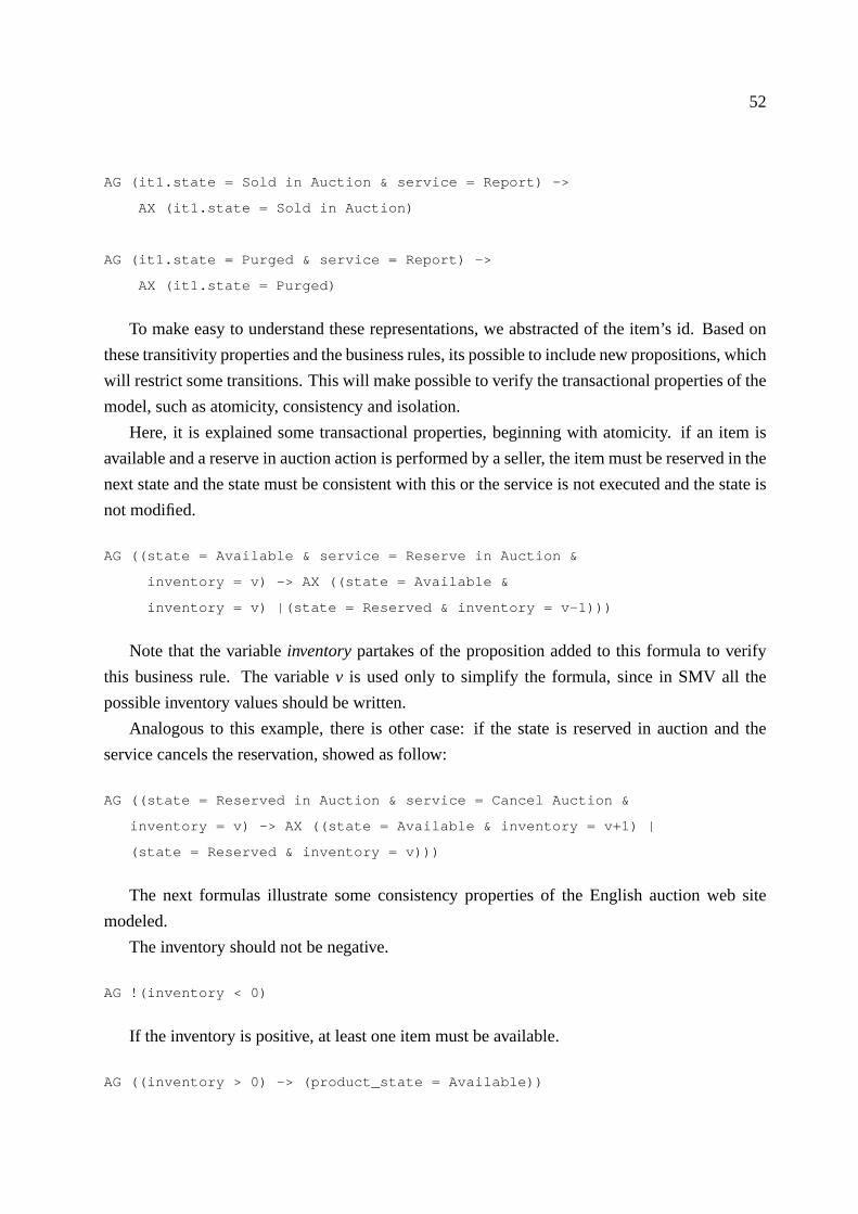
52
AG (it1.state = Sold in Auction & service = Report) ->
AX (it1.state = Sold in Auction)
AG (it1.state = Purged & service = Report) ->
AX (it1.state = Purged)
To make easy to understand these representations, we abstracted of the item’s id. Based on
these transitivity properties and the business rules, its possible to include new propositions, which
will restrict some transitions. This will make possible to verify the transactional properties of the
model, such as atomicity, consistency and isolation.
Here, it is explained some transactional properties, beginning with atomicity. if an item is
available and a reserve in auction action is performed by a seller, the item must be reserved in the
next state and the state must be consistent with this or the service is not executed and the state is
not modified.
AG ((state = Available & service = Reserve in Auction &
inventory = v) -> AX ((state = Available &
inventory = v) |(state = Reserved & inventory = v-1)))
Note that the variableinventorypartakes of the proposition added to this formula to verify
this business rule. The variablev is used only to simplify the formula, since in SMV all the
possible inventory values should be written.
Analogous to this example, there is other case: if the state is reserved in auction and the
service cancels the reservation, showed as follow:
AG ((state = Reserved in Auction & service = Cancel Auction &
inventory = v) -> AX ((state = Available & inventory = v+1) |
(state = Reserved & inventory = v)))
The next formulas illustrate some consistency properties of the English auction web site
modeled.
The inventory should not be negative.
AG !(inventory < 0)
If the inventory is positive, at least one item must be available.
AG ((inventory > 0) -> (product_state = Available))

53
Finally some examples of isolation are presented. If there are two seller actors, one reserving
the item in auction and another one canceling the auction of the item of the same product, the
inventory must be kept consistent after the execution of both services:
AG ((seller1_service = Reserve in Auction & seller2_service =
Cancel Auction & inventory = v) -> AX (inventory = v))
In the case ofinventory = 0, the reservation service can not be preceded by the cancellation
service. So, to solve this problem we decide to give priority to the seller actor that wants to
cancel the reservation. In a similar way, we specified all the other business rules and verify their
veracity.
This version of the model has 7 modules (corresponding to 5 processes: item, buyer actor,
seller actor, product, system), which corresponds to 226 lines of SMV code, and 30 properties
verified.
3.3.4 Execution or Architectural Level
In this stage we added new modules to represent the e-commerce system as real as possible.
So it is included the web server, transaction server and database server in the model. Thus, the
properties are related to requests, instead of services.
In this level it is not identified new properties related to business rules since all of them
were verified in the previous levels. However, it was necessary to check the functioning of the
architectural components, which demands the verification of new properties.
The final version of the model has 8 modules (corresponding to 6 processes), which represent
two buyer actors, a seller actor, the system (English auction server), the web server, the transac-
tion server, two items (database server). The complete model demanded 693 lines of SMV code,
and more than 70 properties were verified. The following code shows part of the formal model
that has been written by the designer:
MODULE main
VAR
ba1_www_socket: boolean;
sa1_www_socket: boolean;
...
ba1: process buyer_agent(1, ..., www_shop_socket_2);
sa1: process seller_agent(3, ...,www_shop_socket_3);
www: process webServer(shop_www_socket_1, ..., www_shop_socket_3);
...

54
it1: process item(1,sh.item_id,www_serv_req_1, ...,www_serv_req_3);
it2: process item(2,sh.item_id,www_serv_req_1, ...,www_serv_req_3);
ASSIGN
init(ba1_www_socket) := 1;
init(ba2_www_socket) := 1;
...
init(www_ba2_socket) := 0;
init(www_sa1_socket) := 0;
DEFINE
www_serv_resp_1:= www.serv_resp_1;
www_serv_resp_2:= www.serv_resp_2;
...
sh_user_session_1 := sh.user_session_1;
sh_user_session_2 := sh.user_session_2;
SPEC AG !(sh.em_uso = 1 & sh.em_uso = 2)
SPEC EF (sh.em_uso = 0)
...
SPEC EF (ba1_opp_req_1 = ho)
SPEC EF(www_serv_resp_1 = sl_resp)
...
SPEC AG(sh.user_session_1 = home) -> EF (sh.user_session_1 = search)
SPEC AG(sh.user_session_1 = home) -> EF (sh.user_session_1 = browse)
MODULE shop(www_shop_socket_1, ..., www_sa1_socket)
VAR
user_session_1: {home, select, search, browse, add, pay, error};
shop_www_socket_3: boolean;
item_id : 0..2;
quantity_item: 0..2;
...
ASSIGN
init(user_session_1) := home;
init(user_session_2) := home;
next(available) := case
available = 0 & quantity_item > 0 : 1;
available = 1 & quantity_item = 0 : 0;
...

55
available = 1 & www_serv_req_1=pa_req : 1;
available = 1 & www_serv_req_2=pa_req : 1;
1: available;
esac;
next(quantity_item) := case
www_serv_req_1 = ad_req & quantity_item > 1 &
www_shop_socket_1=1: quantity_item - 1;
www_serv_req_1 = ad_req & quantity_item = 1 &
em_uso=1 & www_shop_socket_1=1 : quantity_item - 1;
...
www_serv_req_2 = di_req & quantity_item < 2 &
www_shop_socket_2=1: quantity_item + 1;
1: quantity_item;
esac;
next( bits) := case
bits = 0 & www_serv_req_1 = di_req & www_shop_socket_1=1
: bits + item_id;
bits = 1 & www_serv_req_1 = di_req & item_id =2 &
www_shop_socket_1=1 : bits + item_id;
...
1: bits;
esac;
next(item_id) := case
bits = 0 : item_id = 0;
bits = 1 : item_id = 1;
bits = 2 : item_id = 2;
bits = 3 : item_id = {1,2};
1: item_id;
esac;
next(shop_www_socket_1) := case
shop_www_socket_1 = 0 & www_shop_socket_1 = 1: 1;
shop_www_socket_1 = 1 & www_ba1_socket = 1: 0;
1: shop_www_socket_1;
esac;
...

56
next(shop_www_socket_3) := case
shop_www_socket_3 = 0 & www_shop_socket_3 = 1: 1;
shop_www_socket_3 = 1 & www_sa1_socket = 1: 0;
1: shop_www_socket_3;
esac;
...
FAIRNESS running
Note that, in order to use the Formal-CAFE methodology the designer has to know some for-
mal language such as SMV/NuSMV to create the formal model and to describe properties to be
verified. But, it is not an easy task to learn the language of the Verifier and the formalism needed
to specify properties. This is certainly an obstacle to the use of the Formal-CAFE methodology
in the software development process. In order to avoid such obstacle we present, in the next
chapter, the UML-CAFE environment.

57
Chapter 4
The UML-CAFE Environment
As the strategic value of software increases for many companies, the industry looks for tech-
niques to automate the production of software and to improve quality and reduce cost and time-
to-market. These techniques include component technology, visual programming, patterns and
tools. Businesses also seek techniques to manage the complexity of systems as they increase in
scope and scale. In particular, they recognize the need to solve recurring architectural problems,
such as physical distribution, concurrency, replication, security, load balancing and fault toler-
ance. Additionally, the development for the World Wide Web, while making some things simpler,
has exacerbated these architectural problems [48].
In this chapter we describe the UML-CAFE, an environment to help the designer in the
specification and verification of transactional systems.
4.1 Preliminaries
Today, the trend in software is toward bigger, more complex systems [30]. This is due in part
to the fact that computers become more powerful every year leading users to expect more from
them. The appetite for ever-more sophisticated software grows as people learn from one product
release to the next how it could be improved. People want software that is better adapted to their
need which, in turn, merely makes software more complex.
This trend has also been influenced by the expanding use of the internet for exchanging all
kinds of information. Since the last decade the internet has been growing exponentially. As
a new computational infra-structure has became available, new distributed applications which
were previously too expensive or too complex have become common.
In this context, web based systems have become a popular topic for business and academic
research. Electronic Commerce applications, for example, have simplified the access to goods
and services and have revolutionized the economy as a whole. However, web applications tend

58
to generate complex systems [32]. As new services are created, the frequency with which errors
appear has increased significantly.
The UML-CAFE (Figure 4.1) is an environment which can be used to help the designer in
the development of transactional systems, such as web ones. It is divided into the following
components:
1. the UML-CAFE Methodology [53],
2. a set of transformation patterns [52] used to describe and map UML specifications into a
formal model, and
3. the UML-CAFE translator, a tool which automatically translates UML specifications into
the formal model to be verified.
Figure 4.1: The UML-CAFE environment
4.1.1 The UML-CAFE Approach
A successful development project satisfies or exceeds the customer’s expectation, is devel-
oped in a timely and economical fashion, and is resilient to change and adaptation. The develop-
ment, in general, proceeds as a series of iterations that evolve into the final system. Each iteration
consists of one or more of the following methodology components: requirements capture, anal-
ysis, design, implementation, and test.
Usually, to build a complex system the developer abstracts different views of it, builds models
using some notation, verifies that the models satisfy the requirements, and gradually adds details

59
to transform the models into implementation. In this context, an unified notation plays an impor-
tant role once a symbol can mean different things to different people. In our work, we adopt a
general-purpose visual modeling language (UML [48]) to specify and construct the artifacts of a
software system. The next subsection reviews the basic concepts of UML.
4.1.2 The Unified Modeling Language
UML is a language which can be used to visualize, to specify, and to document object ori-
ented systems. It is a standard modeling language used in the software development and visual
modeling which provides a smooth transition between the business domain and the computer
domain.
The main idea behind UML is that every complex system is best approached through a small
set of nearly independent views of a model. The choice of what models one creates has a pro-
found influence upon how a problem is attacked and how a corresponding solution is shaped. In
terms of the views of a model, the UML defines the following graphical components:
• use case diagram: represents a coherent unit of functionality provided by a system, a sub-
system, or a class as manifested by sequences of messages exchanged among the system
and one or more outside interactors (called actors) together with actions performed by the
system.
• class diagram: shows the static structure of the model, in particular, classes and types, their
internal structure, and their relationships to other classes.
• behavior diagrams:
– statechart diagram: used to describe the behavior of a model element such as an object
or an interaction. Specifically, it describes possible sequences of states and actions
through which the element can proceed during its lifetime as a result of reacting to
discrete events (e.g., signals, operation invocations). It is normally used in situations
where asynchronous events occur.
– activity diagram: a special case of a state diagram in which all (or at least most) of
the states are action or subactivity states and in which all (or at least most) of the
transitions are triggered by completion of the actions or subactivities in the source
states. It is recommended to use activity diagrams in situations where all or most of
the events represent the completion of internally-generated actions (that is, procedural
flow of control).
– interaction diagrams which can be divided in:

60
∗ sequence diagram: shows an interaction arranged in time sequence. In partic-
ular, it shows the instances participating in the interaction by their lifelines and
the stimuli that they exchange arranged in time sequence. It does not show the
associations among the objects.
∗ collaboration diagram: shows an interaction organized around the roles in the
interaction and their links to each other. Unlike a sequence diagram, a collabo-
ration diagram shows the relationships among the objects playing the different
roles. On the other hand, a collaboration diagram does not show time as a sepa-
rate dimension.
– implementation diagrams which can be divided in:
∗ component diagram: shows the dependencies among software components, in-
cluding source code components, binary code components, and executable com-
ponents.
∗ deployment diagram: shows the configuration of run-time processing elements
and the software components, processes, and objects that live on them. It is
a graph of nodes connected by communication associations indicating that the
component lives or runs on the node.
These diagrams provide multiple perspectives of the system under analysis or development.
The underlying model integrates these perspectives so that a self-consistent system can be ana-
lyzed and built. These diagrams, along with supporting documentation, are the primary artifacts
that a modeler sees, although the UML and supporting tools will provide for a number of deriva-
tive views. Appendix B describes UML in detail.
In order to translate the UML specifications into formal model to be verified, we have pro-
posed a set of transformation patterns. The next subsection introduces our pattern system.
4.1.3 Transformation Patterns
According to [24], although formal specification and verification methods offer practitioners
some significant advantages over the current state-of-the-practice, they have not been widely
adopted. Despite the automation, one of the major causes is that the users of a finite-state tool
must still be able to specify the system requirements in the specification language of the tool.
In our work, we have defined a pattern system in order to translate UML specifications into
a formal model to be verified. We have considered a special case of transactional systems (web
based applications) and described them by a set of rules that capture important aspects of the
system’s behavior. We denote such rules asbusiness rules- each rule is a norm specifying some
functioning of the application:
1. the actors that interact with the system and their actions,

61
2. the negotiated object and its life cycle,
3. the functionalities expected from the system, and
4. properties that must be satisfied.
We have dividedthe business rulesinto two main groups:
• those related to the construction of the model (identifying valid states and actions over the
object), and
• those used to specify properties of the application.
For example, most properties of a transactional system [3] are related to transactions - an
abstraction of an atomic and reliable sequence of operations. We realize that, in any web based
application, a transaction can be described as a sequence of actions that changes the state of the
negotiated object.
Two important properties must be satisfied in this context: the atomicity and isolation of the
executed transactions. One must show that the concurrency control mechanism implemented is
correct and that the concurrent transactions do not interfere with each other.
There are other rules related to the verification of the model as, for example, the completeness
which asserts that all states and actions are achieved - all states of an item should be reachable
and all actions described for an actor (over an item) should be executed.
Some rules specify invariant aspects of the system, i.e., properties that must be valid during
all the application execution. Finally, there are some rules describing the consistency of the
application. In this case, properties must be guaranteed at some point of the execution, i.e., they
must be valid only if the system reaches certain state.
We use the transformation patterns to generate the model and to specify properties of the
system in order to apply model checking. We have organized our pattern system in the hierarchy
as illustrated by Figure 4.2. This hierarchy distinguishes properties that deal with the construction
and verification of the model:
• Construction
– Actor Pattern: models the actors of the system;
– Object Pattern: models the negotiated item/object;
– Action Pattern: models actions executed by an specific actor;
– Life Cycle Pattern: models the states of the negotiated item and the change caused
by the execution of an actor’s action;
– Isolation Pattern: isolates conflicting actions;

62
Figure 4.2: A Pattern Hierarchy
• Verification
– Invariant Pattern: verifies if a property holds during all the application execution;
– Completeness Pattern: verifies if all states and actions are achieved;
– Transitivity Pattern: verifies if a specific transition holds;
– Consistency Pattern: verifies if a property remains true once a system reaches certain
state;
Each pattern will be explained in the next section as they appear in the UML-CAFE method-
ology.
4.2 The UML-CAFE Methodology
As described in the last Chapter, the Formal-CAFE methodology is an approach which can
be used to design e-commerce systems with model checking support. Although very useful,
the Formal-CAFE methodology still have a great disadvantage: it demands expertise in formal
methods. Unfortunately, it is not a simple task to apply Formal-CAFE. Acquiring a level of
expertise in formal methods can represent an obstacle to its adoption in the software development.
Usually, to build a complex system the developer abstracts different views of it, builds models
using some notation, verifies that the models satisfy the requirements, and gradually adds details
to transform the models into an implementation. In this context, an unified notation plays an
important role.
It is claimed [40] that the use of formal methods can be eased, in the software development
process, if the designer can use tools that reduce, among other things:

63
• the amount of time demanded to develop the system, and
• the gap between the modeling language used to describe the logical model of the applica-
tion, and the formal language used to generate the formal model to be verified.
The UML-CAFE is a methodology based on Formal-CAFE, but used to assist the designer in
the development of web based applications (a case of transactional systems). Apart from Formal-
CAFE, the UML-CAFE methodology is based on UML to guide the developer in the design and
verification processes.
The UML-CAFE is a methodology divided into four phases: conceptual, application, func-
tional, and execution. It can help the designer to specify and verify the system under development
- the main idea is to detect and correct errors before they propagate to later stages. The following
subsections describe each phase of the methodology.
4.2.1 Conceptual Phase
The first phase which captures the requirements of the system is divided into three stages:
Stage 1: In the first stage, the system is described as a set of business rules. Remember that
each rule should describe an important aspect of the application such as:
1. the actors that interact with the system and their actions,
2. the negotiated object and its life cycle,
3. the functionalities expected from the system and,
4. properties that must be satisfied.
Stage 2: Based on the business rules presented in stage 1, the designer has to describe the
actors, their actions, the negotiated object and its states. The designer builds the class diagram
(Figure 4.3) defining the static structure of the model, in particular, classes and types, their in-
ternal structure, and their relationships to other classes. Each actor and the negotiated object is
represented by a parameterized class.
Stage 3: The designer now describes in detail the sequence of actions that each actor can
execute. Actions are described by a transition graph associated to each class. The statechart
(Figure 4.4) shows the state space of a given actor. Each state define an action that can be
executed. Transitions define a valid sequence of operations that can be executed - anonestate
must be defined to indicate that no action is under execution.
In order to generate the formal model to be verified, the actor, action and object patterns are
used as follows:

64
Figure 4.3: Example of Parameterized Classes
Figure 4.4: Example of actor Actions
• Name: Actor Pattern.
• Intent: To model the actors of the system.
• Input: Class Diagram C [{ actor, attribute{ name, domain, default} } ].
• Output: SMV Modules describing the actors and correspondent attributes.
• Mapping: For simplicity, each pattern is described using a structured language such as the one
adopted in [18] - patterns should be written in C, once they are used as semantic actions to the
YACC generator (the one used to generate the UML-CAFE translator as described in Chapter 1).

65
function actor(C[{actor, attribute{name, domain, default}}])
for all p in C do
label( MODULE p.actor (id) )
label( VAR )
for all q in p.attribute do
label ( q.name : q.domain; )
if exists p.attribute.default
label ( ASSIGN )
for all q in p.attribute
if q.default not empty
label ( init(q.attribute) := q.default; )
According to the actor pattern the following SMV module can be generated:
MODULE Actor_1(id)
VAR
action: { none, action_1, ..., action_N };
attribute_1: type;
...
attribute_N: type;
ASSIGN
init(action) := none;
init(attribute_1) := attribute_1 initial value;
...
Action pattern is used to translate the actions executed by actors:
• Name: Action Pattern.
• Intent: To model the actions executed by the actors.
• Input: Statechart G [ (states, transitions, type) ].
• Output: SMV Modules describing the actors and correspondence actions.
• Mapping:

66
function Action(object_name, G)
Append( MODULE object_name )
label( next(action) := case )
repeat
select s in G.states; mark s;
label ( action = s : { )
for all f in G.transitions[s, f] do
label ( f, )
label ( }; )
until all s is marked
label( esac; )
label( FAIRNESS running )
According to the action pattern the following actions are modeled:
Module Actor_1(id)
Assign
...
NEXT(ACTION) := CASE
ACTION = ACTION_1 : { NONE, ... };
...
ACTION = ACTION_N : { NONE, ... };
ESAC;
FAIRNESS RUNNING
Note that the class diagram and associated action’s graphs are used to generate the first ver-
sion of the model to be verified. Each parameterized class is translated into a module in the
formal model. Actions are represented by a variable namedaction and each transition graph
describes a change in the value of the correspondingactionvariable. In this phase the designer is
able to verify if the business rules are specified correctly. For example, is it true that all actions
described can be executed? The designer applies the completeness pattern in order to verify such
fact:
• Name: Completeness Pattern.
• Intent: To verify if all possible values of an attribute are modeled/achieved.
• Input: At(name, attribute, domain).
• Mapping: EF ( p )

67
function Completeness( At(name, attribute, domain) )
Append( MODULE At.name )
repeat
select v in At.domain; mark v;
label ( SPEC EF (attribute = v ) )
until all v in At.domain is marked
The following code checks the completeness properties:
MODULE Actor_1(id)
...
-- Completeness pattern: EF (ACTION = <A>)
SPEC EF (action = action_1)
...
SPEC EF (action = action_N)
Finally, based on the object pattern the negotiated object is modeled:
• Name: Object Pattern.
• Intent: To model the negotiated item/object.
• Input: Class Diagram C [ A{ actor, at{ name, domain, default} } , O{ object, at{ name, domain,
default} } ].
• Output: SMV Module describing the negotiated object and correspondent attributes.
• Mapping:
function Object(C [ A {actor, at{name, domain, default}},
O {object, at {name, domain, default }} ])
label( MODULE object_name (id )
for all q in A.at
label ( ’,’ + actor + ’_’ + q. name )
label( ’)’ ) label( VAR )
for all q in O.at do
label ( q.name : q.domain; )
if exists O.at.default not empty
label ( ASSIGN )
for all q in O.at
if q.default not empty
label ( init(q.attribute) := q.default; )

68
The following code is now generated:
MODULE Negotiated_Object(id, actor_1, ..., actor_N)
VAR
state : { state_1, ..., state_N };
attribute_1 : type;
...
ASSIGN
init(state) := initial state;
4.2.2 Application Phase
The second phase defines the behaviors of the system. It describes the life cycle of the
negotiated object, its interactions with the actors and actions. Moreover, the states are modeled
and the system’s functionality is described - a context diagram is presented. Properties, such as
completeness and invariants, are verified. At this phase, all elements are modeled through use
cases, as defined by the following stages:
Stage 4: Each use case is documented with a flow of events required to accomplish its be-
haviors - a flow of events is a sequence of transactions, or events, performed by the system. It
should contain detailed information written in terms of what the system should do, regardless of
how the system accomplishes the task.
Table 4.1 describes the UML-CAFE template to create the flow of events. The template is
based on RUP [30], and is used to model information presented in the application phase.
Table 4.1: The UML-CAFE TemplateElement Description<Name> Use Case NamePreconditions Conditions that must be obeyed to allow the execution of the use caseMain Flow Normal sequence of events for the use caseAlternative Flows Alternate or exceptional flowsStatechart Diagram that represents the sequence of states that the system goes
throughObservations Additional information about the use cases
Stage 5: Here, the statechart diagram is used to model the discrete stages of a system’s
lifetime. The statechart diagram shows the sequence of states that the negotiated object goes
through, the events that cause a transition from one state to another, and the actions that result
from a state change (Figure 4.5).
Each state represents a snapshot during the life of a system which satisfies some condition
or waits for some event. Transitions are represented by actions which indicate the operation

69
Figure 4.5: The Life Cycle of the Negotiated Object
executed by an actor. There is also a guard condition that must be met before the transition is
taken. As long as the guard condition remains false, the transition will not occur.
Stage 6: In this stage the developer reviews in detail the precedent stages and collects, for
each use case, additional information such as invariant and consistency properties. These prop-
erties are described in the documentation section (Figure 4.6) which is part of the UML class
specification.
Figure 4.6: Property Description
The UML-CAFE has been designed to be an incremental methodology. So, as the design

70
evolves new information must be added to the formal model. Now, the life cycle pattern is used
to model the life cycle of the negotiated object:
• Name: Life Cycle Pattern.
• Intent: To represent the life cycle graph of the negotiated object/item.
• Input: Set of statechart diagram (each diagram describes a particular use case for the system).
Formally, S is a set of D(V, T, L) where:
– V is a set of states,
– T ⊆ V × V is a transition relation and,
– L(guardcondition, action) is a function that labels T.
• Output: Module describing the life cycle of the negotiated object.
• Mapping: AG( p→ AX(q) )
function Life_Cycle(object_name, S : { D(V, T, L) })
Append( MODULE object_name )
label( next(state) := case )
for all D in S do
repeat
select v in D.V; mark v;
for all v in D.T[v, f] do
label ( state = v & )
if (D.L(guard_condition) and D.L(action) is not null)
label ( D.L(guard_condition) & D.L(action))
else
label ( D.L(action) )
label ( : f; )
until all v in D.V is marked
label( 1 : state; )
label( esac; )
label( FAIRNESS running )
Now, the following module is generated:

71
MODULE Negotiated_Object(id, actor_1, ..., actor_N)
...
ASSIGN
...
next(state) := case
state = state_1 & (guard_condition_1) & (action_1) : state_2;
...
state = state_Y & (guard_condition_Y) & (action_Y) : state_N;
1 : state;
esac;
FAIRNESS running
Note that modules are created and incrementally modified as the design evolves. This is the
main idea of the UML-CAFE methodology - errors can be identified early in the design and
corrected before they propagate to later stages. Again, the designer is able to verify if the design
match the business rules specified. For example, some business rules describe the consistency
aspects of the system - is it always true that if the system is in a state where a propertyp is true
than from now on,q will be always true? Other rules specify the invariant aspects - is a property
p always true? In time, is there any state of the negotiated item that can not be reached? The last
one can be checked using the completeness pattern. The consistency and invariant patterns are
used to model the other properties:
• Name: Consistency Pattern.
• Intent: To verify if a property remains true once a system reaches certain state.
• Input: E = set of ( expression X expression )
• Mapping: AG ( p→ AG (q) )
function Consistency( E { expression X expression } )
Append( MODULE name )
for all (e1, e2) in E do
label ( SPEC AG ( (e1) -> AG (e2) ) )
• Name: Invariant Pattern.
• Intent: To verify if a property is valid in all states.
• Input: E = set of ( expression ).

72
• Mapping: AG ( p )
function Invariant( E { expression } )
Append( MODULE name )
for all e in E do
label ( SPEC AG ( e ) )
The following generated code checks the consistency and invariant properties:
MODULE name(id, ...)
...
-- consistency Pattern: AG ( expression_1 -> AG ( expression_2 ) )
SPEC AG ( expr_1 -> AG ( expr_2 ) )
...
-- Invariant Pattern: AG ( expr )
SPEC AG ( expr )
...
4.2.3 Functional Phase
This phase models the services provided by the system. While each action comprises simple
operations such as allocating an item for future purchase, services perform full transactions -
actually, services are sequences of actions. This phase is divided into three stages:
• Stage 7:A set of services is defined for the use cases previously identified. Now, each use
case is completed with a description for the service required.
• Stage 8:Once services are defined, the designer describes the interaction among instances
- the UML sequence diagram is used to specify each service.
• Stage 9: Each service consists of a sequence of actions. Note that although actions are
atomic by definition, not every sequence of actions is atomic. So, in this stage the services
and their concurrent aspects are described. The designer identifies all sequences that must
be executed isolated - considered as an atomic transaction.
Our experience pointed out that some concurrent activities can not be fully described by
sequence diagrams. There are many situations where activityA1 of processP1 and activityA2 of
processP2 must exclude each other if the execution ofA1 may not overlap the execution ofA2. If
P1 andP2 simultaneously attempt to execute their respective activities,Ai, then one must ensure
that only one of them succeeds. The losing process must block; that is, it must not proceed until

73
the winning process completes the execution of its activityA. This problem is known as mutual
exclusion.
Activity diagrams can define sequence of actions that are executed concurrently. But, as
sequence diagrams, they can not describe actions that must be executed in mutual exclusion. In
order to support such aspect, we have proposed extensions in the UML activity diagram - in fact,
we have produced a conservative extension since we have not modified meta-classes defined
in UML 1. Figure 4.7 shows the UML meta-model for activities as described in the UML 2.0
Superstructure Specification [41].
Figure 4.7: UML meta-model - Activity
UML 2.0 defines a new abstract class, Activity Group, for defining sets of nodes and edges
in an activity. Activity groups (Figure 4.8) are a generic grouping construct for nodes and edges.
They have no inherent semantics, but some constraints are specified:
• All nodes and edges of the group must be in the same activity as the group.
• No node or edge in a group may be contained by its subgroups or its containing groups,
transitively.
• Groups may only be owned by activities or groups.
1Detailed works extending UML can be seen in [27, 51].

74
Figure 4.8: UML meta-model - Activity Group
The activity group can be used to define, for example, an interruptible activity region - a
group that supports termination of tokens flowing in the portions of an activity. An interrupt-
ible activity region contains activity nodes, and when a token leaves an interruptible region, via
edges designated by the region as interrupting edges, all tokens and behaviors in the region are
terminated. Figure 4.9 shows an interruptible activity region and an example of its use.
(a) Interruptible Activity Region
(b) Example
Figure 4.9: UML meta-model - Interruptible Activity Region

75
In the same way, we have defined a new class, isolated activity region, to support the mutual
exclusion for sequence of operations (activities). We did not create a stereotype� isolated �and refer it to the UML meta-class interruptible activity region based on the difference between
isolated and interruptible regions - an isolated region is executed in mutual exclusion and contains
activity nodes controlled by a flag (semaphore). Figure 4.10 shows the isolated activity region
and its notation.
(a) Isolated Activity Region
(b) Isolated Activity Region Notation
Figure 4.10: UML meta-model - Isolated Region
Figure 4.11 shows the semantic and an example of its use. The execution of activities in
region1 may not overlap the execution of activities inregion2. If there is a simultaneously
attempt to execute their respective activities, then only one of them succeeds.
Back to the UML-CAFE methodology, the isolation pattern can be used in this phase to
isolate conflicting services:
• Name: Isolation Pattern.
• Intent: To represent the isolation of conflicting actions.
• Input: Activity diagram (each swimlane describes a particular service).
• Output: Flag to control conflicting actions.
• Mapping:

76
Figure 4.11: Isolation of Conflicting Actions
function Isolation(A:{Swimlane(V(entering,critical,exiting),T))
label( next(flag) := case )
for all D in A.Swimlane do
repeat
select v in D.V_entering;
mark v;
label(flag = 0 &)
for all v in D.V_entering, v in T [v, f] do
label(actor.action = v |)
until all v in D.V is marked
label (& next(actor.action) = f : value; )
repeat
select v in D.V_critical;
mark v;
label(flag = value & actor.action = v &)
for all v in D.V_critical[v, f], v in T [v, f] do
label ( next(actor.action) = v | )

77
until all v in D.V is marked;
label(: value;)
repeat
select v in D.V_exiting;
mark v;
label(flag = value & actor.action = v &)
for all v in D.V_exiting[v, f], v in T [v, f] do
label ( next(actor.action) = v | )
until all v in D.V is marked;
label(: 0; )
The following sequence models the isolation:
next(flag) := case
--- entering in critical section
turn = 1 & flag = 0 &
(actor1.action = Entering Action_1-1 | ... |
actor1.action = Entering Action_1-N ) &
(next(actor1.action) = Critical Action_1-1) : 1;
turn = 2 & flag = 0 &
(actor2.action = Entering Action_2-1 | ... |
actor2.action = Entering Action_2-N ) &
(next(actor1.action) = Critical Action_2-1) : 2;
...
--- critical section
flag = 1 & (actor1.action = Critical Action_1-1 ) &
(next(actor1.action) = Critical Action_1-2) : 1;
flag = 2 & (actor2.action = Critical Action_2-1 ) &
(next(actor2.action) = Critical Action_2-2) : 2;
...
--- exiting critical section
flag = 1 & (actor1.action = Critical Action_1-N) &
( (next(actor1.action) = Exiting Action_1-1 | ... |
(next(actor1.action) = Exiting Action_1-N )) : 0;
...
esac;
Note that a variableturn is create in order to avoid starvation: if both actor1 and actor2 want
to enter their critical section, one of them can be infinitely waiting to do so. Variableturn is

78
modeled as follows:
Consider:
A = (actor1.action = Entering Action_1-1 | ... |
actor1.action = Entering Action_1-N ) &
(next(actor1.action) = Critical Action_1-1)
and
B = (actor2.action = Entering Action_2-1 | ... |
actor2.action = Entering Action_2-N ) &
(next(actor1.action) = Critical Action_2-1)
next(turn) := case
--- actor1 wants to enter its critical section
(A) & (!B) : 1;
--- actor2 wants to enter its critical section
(!A) & (B) : 2;
--- actor1 and actor2 want to enter their critical section
--- actor1 has already entered before
--- now, it is time to let actor2 enter its critical section
(turn = 1) & (A) & (B) : 2;
--- actor1 and actor2 want to enter their critical section
--- actor2 has already entered before
--- now, it is time to let actor1 enter its critical section
(turn = 2) & (A) & (B) : 1;
esac;
4.2.4 Execution Phase
In this phase it is used physical diagrams such as deployment diagrams and component di-
agrams - they are used to give descriptions of the physical information about a system (Fig-
ure 4.12). Although the UML-CAFE can describe the physical aspects of the application, none
verification is done once the business rules are not affected by the physical environment.
The main idea is to describe the interconnection between the components and the customers
interface. The definition of the execution environment must be coherent with the description
of the services and functionalities that compose the functional phase. This description must be
done in terms of paradigms of implementation, and system primitives. Examples of paradigms
are client-server, remote procedure calls and message exchange. In terms of system primitives,
we must enumerate resources such as TCP/IP support and ability to dofork andrsh.

79
Figure 4.12: Physical Diagrams
Once the types of communication and cooperation between the components are defined, it
is necessary to specify the protocols to be used for this communication. Thus, for each service
it must be indicated (in the case of standardized protocols) or be described the protocols used
for communication between the components. Examples of standardized protocols are the pro-
tocol HTTP, standard ODBC, used to access the database manager systems(DBMS), and CGI
interface, used for execution of dynamically instantiated tasks.
The definition of the protocols must specify the types, purpose and message format. The
message type identifies the system primitive used (i.e., RPC, TCP/IP). The protocol can be briefly
described by the time diagram of necessary messages for the achievement of the service. For
each message the following information must be specified: purpose, type (that indicates the
basic protocol to be used), sender and receiver, content, and format.
This subsection completes the description of the UML-CAFE Methodology. In the next
Chapter it is illustrated its use through an example. The next section describes the UML-CAFE
translator.
4.3 The UML-CAFE Translator
The UML-CAFE Translator is a parser which takes UML specifications as its input and pro-
duces a corresponding parse tree for the formal model to be verified. It reads the source program
(UML specifications), discovers its structure and processes it generating the target program (for-
mal model). Lex and Yacc [37] have been used to implement the UML-CAFE translator.
Lex helps write programs whose control flow is directed by instances of regular expressions
in the input stream. It is well suited for editor-script type transformations and for segmenting

80
input in preparation for a parsing routine. Lex source is a table of regular expressions and corre-
sponding program fragments. The table is translated to a program which reads an input stream,
copying it to an output stream and partitioning the input into strings which match the given ex-
pressions. As each such string is recognized the corresponding program fragment is executed.
The recognition of the expressions is performed by a deterministic finite automaton generated by
Lex. The program fragments written by the user are executed in the order in which the corre-
sponding regular expressions occur in the input stream.
Computer program input generally has some structure; in fact, every computer program that
does input can be thought of as defining an ”input language” which it accepts. An input language
may be as complex as a programming language, or as simple as a sequence of numbers. Unfor-
tunately, usual input facilities are limited, difficult to use, and often are lax about checking their
inputs for validity.
Yacc provides a general tool for describing the input to a computer program. The Yacc user
specifies the structures of his input, together with code to be invoked as each such structure is
recognized. Yacc turns such a specification into a subroutine that handles the input process;
frequently, it is convenient and appropriate to have most of the flow of control in the user’s
application handled by this subroutine.
The UML-CAFE translator is divided into two components: the lexical analyzer and parser
described in the following subsections.
4.3.1 Lexical Analyzer
The main task of the lexical analyzer is to read an input and translate it into a sequence of
tokens which can be used by the parser in the syntactical analysis phase. The following tokens
have been defined by the lexical analyzer:
• object, parameterizedclass, quid, classattributes, classattributelist, classattribute, type,
initv, cardinality, cardinalityvalue, value, parameter, parameters, statemachine, activity,
transitions, states, transitionlist, statetransition, supplier, sendevent, condition, docu-
mentation, consistence, invariant, id, initvvalue, transitivity, idvalue, relop, addop, mu-
lop, list, label, state, quidu and neg.
Table 4.2: Examples of UML-CAFE tokens and their structureToken Regular expressionneg !addop +,−, |relop >=, <=, >, <, =statemachine StateMachine, statemachineclassattribute ClassAttribute... ...

81
Each token is described by a rule which is a regular expression as shown in Table 4.2. The
following code shows part of the UML-CAFE lexical analyzer:
%{
#include "symbol.h"
extern YYSTYPE yylval;
%}
ws [ \t\n]
digit [0-9]
letter [a-zA-Z]
ID ({letter}|{digit}|_|\$)+
IDC ({ID}|{ID}\.{ID})
%%
{ws}
"\"" | "(" | ")" | "{" | "}" { return yytext[0]; }
"!=" { strcpy(yylval.lexeme, yytext); return relop; }
"!" { strcpy(yylval.lexeme, yytext); return neg; }
"&" { strcpy(yylval.lexeme, yytext); return mulop; }
...
{IDC} {
int token = lookup(yytext);
if (token == id_value)
strcpy(yylval.lexeme, yytext);
return token;
}
. { return yytext[0]; }
%%
The input to the lexical analyzer is an UML specification (descriptions of the system being
developed). The main idea is to translate the specification into tokens to be used in the syntactical
analysis. Following is an example of the input file:
(object Parameterized_Class "Buyer"
quid "3F858E8000E7"
class_attributes (list class_attribute_list
(object ClassAttribute "action"
quid "3F858E8000E8"
type "{ join, confirm_adhesion, cancel_adhesion, none }"
initv "join")

82
(object ClassAttribute "adhesion_quantity"
quid "3F858E8000E9"
type "1..10"
initv "1..10")
...
statemachine (object State_Machine "State/Activity Model4"
quid "3FA7D33F00EC"
states (list States
(object State "none"
quid "3FA7D34801AD"
transitions (list transition_list
(object State_Transition
quid "3FA7D39D005B"
supplier "cancel_adhesion"
quidu "3FA7D3650082"
sendEvent (object sendEvent
quid "3FA7D39D005E"))
...
(object State "join"
quid "3FA7D34F0027"
transitions (list transition_list
(object State_Transition
quid "3FA7D3BF00FA"
supplier "confirm_adhesion"
quidu "3FA7D3530131"
sendEvent (object sendEvent
quid "3FA7D3BF00FD"))
cardinality (value Cardinality "1..1")
parameters (list Parameters
(object Parameter "id"
quid "3F858E8000EB")))
...
(object Parameterized_Class "Automatic_Agent"
quid "3F858E800100"
class_attributes (list class_attribute_list
...

83
4.3.2 Parser
A parser has been generated in order to translate the UML specifications into the formal
model to be verified. The main idea is to translate the UML specifications (input file) into tokens
(lexical analysis) and then parse it (syntactical analysis). During the parsing, semantic actions
are executed and the input file is converted into the formal model - transformation patterns were
used as semantic actions to generate the formal model (see Appendix C for details).
The UML-CAFE translator has been generated using YACC. The input to YACC is a BNF
grammar describing the structure of the input file. Following is the grammar describing it:
Module : ParamClass
ParamClass : ParamClass ’(’ object parameterized_class
id_value Body ’)’
|
;
Body : quid id_value Documentation Attributes StateMachine
Cardinality Parameter
;
Documentation : documentation Operator
|
;
Operator : Operator Spec
|
;
Spec : addop transitivity ’(’ Expression ’,’ Expression ’,’
Expression ’)’
| addop consistency ’(’ Expression ’,’ Expression ’)’
| addop invariant ’(’ Expression ’)’
| addop completeness ’(’ Expression ’)’
| addop isolation ’(’ Expression ’,’ Expression ’)’
| addop atomicity ’(’ Expression ’,’ Expression ’)’
;
Attributes : class_attributes ’(’ list class_attribute_list
ListAtribClass ’)’
|
;
ListAtribClass : ListAtribClass ’(’ object class_attribute id_value
quid id_value type Type Init
| ;

84
Type : id_value
| id_value ’.’ ’.’ id_value
| ’{’ ListEnum ’}’
;
ListEnum : id_value
| id_value ’,’ ListEnum
;
Init : initv id_value ’)’
| initv id_value ’.’ ’.’ id_value ’)’
| initv ’{’ ListaEnumIni ’}’ ’)’
| ’)’
;
ListaEnumIni : id_value
| id_value ’,’ ListaEnumIni
;
StateMachine : statemachine ’(’ object statemachine state mulop activity
id_value quid id_value states ’(’ list states StateList
’)’ ’)’
|
;
StateList : StateList ’(’ object state Expression
quid id_value Transition type id_value ’)’
|
;
Transition : Transitions ’(’ list transition_list
StateTransitionList ’)’
|
;
StateTransitionList : StateTransitionList ’(’ object state_transition
quid id_value Label supplier Expression
quidu id_value Condition Action send_event ’(’
object send_event quid id_value ’)’ ’)’
|
;
Label : label id_value
| label
| ;

85
Condition : condition Expression
|
;
Action : id_value ’(’ object id_value Expression
quid id_value ’)’
|
;
Expression : Expression relop Exp_Add
| Exp_Add
;
Exp_Add : Exp_Add addop Exp_Mul
| Exp_Mul
;
Exp_Mul : Exp_Mul mulop Exp_Neg
| Exp_Neg
;
Exp_Neg : neg Expression
| ’(’ Expression ’)’
| ’{’ id_value ’,’ Expression ’}’
| id_value
;
Cardinality : cardinality ’(’ value
cardinality id_value ’.’ ’.’ id_value ’)’
;
Parameters : parameters ’(’ list parameters ParamList ’)’
;
ParamList : ParamList ’(’ object parameter id_value
quid id_value ParamType
|
;
ParamType : type id_value quidu id_value ’)’
| type id_value ’)’
| ’)’
;
This section completes the description of the UML-CAFE Environment. The next chapter
illustrates the use of UML-CAFE through a buyer group case study - a typical web based appli-
cation.

86
Chapter 5
UML-CAFE Case Study
In this chapter we illustrate our methodology through a buyer group application. This is a
typical web application where a group is created to aggregate similar demands in order to buy
goods at low cost. Following, we describe the application.
The first step is to publish the buyer group. The buyer group is published by an Association
Administrator. In this example, buyers join a group only once and should inform the quantity
and maximum value each of them is willing to pay for the item being traded.
Once the group is published if the deadline to join a group is met and there is no adhesion,
then the group is cancelled; otherwise the group changes to a confirmation state. If the group
is in confirmation state, the association administrator can cancel or confirm it. If the group is
confirmed it changes to the negotiation state - the administrator chooses the negotiation modality
and waits for sellers send their proposals.
If the deadline to receive proposals is achieved and none of the proposals is the winner, then
the group is cancelled; otherwise it changes to a confirm adhesion state. Each adhesion is checked
against the winner proposal. For each adhesion, if the winner proposal price is higher than the
maximum value informed in the adhesion, then this adhesion is get confirmed, otherwise it is
cancelled.
As soon as the deadline to confirm adhesion is achieved and at least one adhesion is con-
firmed, the buyer group changes to a confirm proposal state. If the seller confirms its proposal,
the buyer group goes to a closed state; otherwise it is cancelled. Once the group is closed it
should remain closed. In the next sections we illustrate each phase of UML-CAFE.
5.1 Conceptual Phase
The first step in the design, as defined by our methodology in stage 1, is to describe the
system as a set of business rules. Following, we present them:

87
1. The minimum quantity in an adhesion must be greater than zero.
2. The maximum value specified in an adhesion must be greater than zero.
3. If the buyer group is in theUnpublishedstate and the association administrator publish it,
then the buyer group will change to anAdhesionstate.
4. If the buyer group is in theAdhesionstate and the buyer makes an adhesion to this buyer
group, then the buyer group will continue in theAdhesionstate.
5. If the buyer group is in theAdhesionstate and the deadline to make adhesion is achieved
and there is at least one adhesion, then the buyer group will change to aConfirmationstate.
6. If the buyer group is in theAdhesionstate and the deadline to make adhesion is achieved
and there is no adhesion, then the buyer group will change to aCancelledstate.
7. If the buyer group is in theConfirmationstate and the association administrator cancels it,
then the buyer group will change to aCancelledstate.
8. If the buyer group is in theConfirmationstate and the association administrator confirms
it, then the buyer group will change to aConfirmedstate.
9. If the buyer group is in theConfirmedstate and the association administrator choose the
negotiation modality, then the buyer group will change to aNegotiationstate.
10. If the buyer group is in theNegotiationstate and the seller delivers a proposal, then the
buyer group will continue in theNegotiationstate.
11. If the buyer group is in theNegotiationstate and the deadline to receive proposals is
achieved and none of the proposals is the winner, then the automatic agent cancels the
buyer group, modifying it to aCancelledstate.
12. If the buyer group is in theNegotiationstate and the deadline to receive proposals is
achieved and there is a winner proposal, then the automatic agent changes the buyer group
state to aConfirm Adhesionstate and the automatic agent performs an action according to:
(a) For each adhesion of the buyer group, if its maximum value is greater than the winner
proposal price, then this adhesion is get confirmed and the buyer group continues in
theConfirm Adhesionstate.
(b) For each adhesion of the buyer group, if its maximum value is lower than the winner
proposal price, then this adhesion is get cancelled and the buyer group continues in
theConfirm Adhesionstate.

88
13. After the business rule number 12 has already completed, then if the buyer group is in the
Confirm Adhesionstate and the buyer confirm the adhesion, then the buyer adhesion is
confirmed and the buyer group continues in theConfirm Adhesionstate.
14. After the business rule number 12 has already completed, then if the buyer group is in
theConfirm Adhesionstate and the buyer cancels the adhesion, then the buyer adhesion is
cancelled and the buyer group continues in theConfirm Adhesionstate.
15. If the deadline to confirm adhesion is achieved and none of the adhesion is confirmed, then
the buyer group changes to aCancelledstate.
16. If the deadline to confirm adhesion is achieved and at least one adhesion is confirmed, then
the buyer group changes to aConfirm Proposalstate.
17. If the buyer group is in theConfirm Proposalstate and the seller confirms its proposal,
then the buyer group changes to aClosedstate.
18. If the buyer group is in theConfirm Proposalstate and the seller cancels its proposal, then
the buyer group changes to aCancelledstate.
19. Once the buyer group is closed it must remain closed.
20. Once the buyer group is cancelled it must remain in this state.
The next step, according to stage 2, is the identification of actors, their attributes and domains,
as shown in Table 5.1. The designer builds the class diagram as illustrated in Figure 5.1.
Table 5.1: Actors and AttributesActor Attributes Domain DefaultAutomaticagent action {cancelgroup, ..., generateorders, none} noneAdministrator action {creategroup, ..., choosemodality} noneSeller action {createproposal, ..., cancelproposal} none
proposalvalue 1..10 1..10Buyer action {join, ..., canceladhesion} none
adhesionquantity 1..10 1..10max value 1..10 1..10
According to the actor pattern, the following code is generated:

89
Figure 5.1: Class Diagram
MODULE Buyer(id)
VAR
action: { confirm_adhesion, ..., join, none };
adhesion_quantity: 1..10;
max_value: 1..10;
ASSIGN
init(action) := none;
init(adhesion_quantity) := 1..10;
init(max_value) := 1..10;
...
The negotiated object, its attributes and domains are defined as illustrated in Table 5.2. The
object patternis used to model the negotiated object:
MODULE Buyer_Group(id, seller, ..., buyer)
VAR
state : { Confirm_Adhesion, ..., Closed };
...
ASSIGN
init(state) := Unpublished;

90
Table 5.2: Negotiated Object and AttributesAttributes Domain Defaultstate { Confirm Adhesion, ..., Negotiation, Closed} Unpublishedhasadhesion boolean -adhesiondeadline boolean -haswinner proposal boolean -proposaldeadline boolean -hasconfirmedadhesion boolean -confirm adhesiondeadline boolean -
A module namedmain is automatically generated - each actor and the negotiated object is a
particular process of the main module:
MODULE main
VAR
administrator1: process Administrator(1);
buyer_group1: process Buyer_Group(1, ..., buyer1 );
...
Each actor must have a transition graph describing its actions as illustrated in Figure 5.2.
Actions are formally modeled based on the action pattern:
Figure 5.2: Administrator Action Diagram
MODULE Administrator(id)
...
ASSIGN
next(action) := case
action = none : { cancel_group, confirm_group, ..., none };
...
action = cancel_group : { none };
esac;

91
Also, in this third stage, the completeness property is automatically generated for each action:
MODULE Administrator(id)
...
-- Completeness Pattern: EF ( p )
SPEC EF( action = none )
...
SPEC EF( action = create_group )
5.2 Application Phase
The second phase defines the system’s functionality. Based on the information described, the
designer is able to define the behaviors of the system under development. At this point the use
cases for the system are identified. Figure 5.3 shows the buyer group context diagram specified
at this phase. Each use case is documented with a flow of events required to accomplish its
behaviors.
Figure 5.3: Buyer Group Context Diagram

92
The Manage Adhesion Use Case is given as an example:
1. Manage Adhesion Use Case
2. Preconditions: (group state = adhesion)
3. Main Flow:
if (buyer.action = join and adhesionquantity> 0 and maxvalue> 0
and not adhesion deadline)then (state = adhesion)
4. Alternative Flows:
• Preconditions: Adhesion deadline
• Steps:
if (automaticagent.action = cancel group and !hasadhesion)
then (state = cancelled)
if (automaticagent.action = confirm and hasadhesion)
then (state = confirmation)
if (buyer.action = join)
then adhesion not accomplished
5. Statechart Diagram: as defined in stage 5 the item’s life cycle related to the use case is
specified as a state transition diagram (Figure 5.4).
Figure 5.4: Manage Adhesion Diagram

93
6. Observations: In stage 6, after reviewing the use case, the invariant and consistency proper-
ties, such asCancelled group is a final state, are registered. The consistency and invariant
properties are registered in the documentation field as depicted in Figure 5.5.
Figure 5.5: Property Description
Note that, consistency properties are described as 2-tuple:consistency(e1, e2). For example,
consistency (state = cancelled, state = cancelled)- once the negotiated object reaches the can-
celled state, it will remain, henceforth, in the cancelled state. Invariant properties are described
as simple tuple:invariant(e). For example,invariant (buyer. adhesionquantity> 0) - the buyer
adhesion to the group must always be positive.
Now, the life cycle of the negotiated object is modeled as illustrated in Figure 5.6. Based on
the life cycle pattern, the states of the negotiated item are modeled:
MODULE Buyer_Group(id, seller, ..., buyer)
...
ASSIGN
...
init(state) := unpublished;
-- Life cycle Pattern: AG(q -> AX(p))
next(state) := case
state = unpublished & administrator.action = create_group : adhesion;
state = adhesion & (buyer.adhesion_quantity > 0 & buyer.max_value > 0
& !adhesion_deadline) & buyer.action = join : adhesion;
...
1 : state;
esac;

94
Figure 5.6: Life Cycle of the Negotiated Object
Again, important properties are checked using the completeness1, consistency and invariant
patterns:
MODULE Buyer_Group(id, seller, ..., buyer)
...
--- Completeness Pattern
SPEC EF(state = Unpublished)
...
--- consistency Pattern
SPEC AG( state = cancelled -> AG (state = cancelled) )
...
--- Invariant Pattern
SPEC AG( buyer.adhesion_quantity > 0)
5.3 Functional Phase
This phase models the services provided by the system. First, as described in stage 7, the
services are defined through detailed business rules, for example:
1The completeness pattern is now used to check if all states are reachable. It is automatically generated for thenegotiated object.

95
1. all deadlines must be initially false;
2. if state = negotiation and adhesiondeadline = true and proposal deadline is achieved then
proposaldeadline = true;
3. an adhesion can be made only in the adhesion state;
4. an adhesion can be confirmed only if state = confirmadhesion, and there is a winner pro-
posal and the proposal deadline is achieved;
Considering theManage Proposal and Confirm AdhesionUse Case, the following services
are defined:
• Automatic agent manages deadline for proposal:
– cancel group if there is no winner proposal;
– validate adhesions if there is a winner proposal:
∗ check proposal value against maximum adhesion’s value;
• Receive seller proposal, If deadline for proposal has not been achieved:
– validate proposal;
– register proposal if it is a valid one;
– ignore proposal, if deadline for proposal is achieved;
Note that the application demands that actions must obey certain timing constraints. Services
can be described in UML through a sequence diagram. But, sequence diagrams can not properly
describe all the concurrent aspects involved such as transactional services and timing constraints.
We have decided to use the UML-RT [28] sequence diagram to describe timing constraints.
Construction marks are used to indicate a time interval to which a constraint may be attached.
We use the UML-RT sequence diagram as illustrated in Figure 5.7. The flag indicates that
a deadline has occurred and, according to it, which actions must be executed. For example, if a
deadline for proposal is achieved, then any new proposal should be rejected; on the other hand,
it should be validated and registered.
Not all concurrent activities can be totally depicted by a sequence diagram. In the example,
a deadline can occur at any time while the seller is making a proposal. If the proposal is valid, it
must be registered no matter if the deadline happens. Note that these two actions form an atomic
transaction. To describe such fact it is used an extend activity diagram. As showed in Figure 5.8,
actions executed by the automatic agent and any proposal instances are concurrent. Note that
both actions, validate and register proposal, are treated as an atomic block - they are isolated
from the others.

96
Figure 5.7: The Manage Proposal and Confirm Adhesion Sequence Diagram
Figure 5.8: The Manage Proposal and Confirm Adhesion Activity Diagram

97
An isolated block can be described through primitives denoted semaphores. The following
code shows the mapping:
MODULE Buyer_Group(id, seller, ..., buyer)
VAR
proposal : { none, valid, invalid, ..., confirmed };
...
ASSIGN
init(has_adhesion) := FALSE;
...
init(proposal) := none;
next (turn) := case
next(automatic_agent.action = Process_Adhesions) &
!(next(seller.action) = Create_Proposal) : 1;
...
1 : turn;
esac;
next (flag) := case
turn = 1 & flag = 0 & automatic_agent.action = Process_Adhesions : 1;
...
1 : 0;
esac;
next(state) := case
...
flag = 1 & state = Negotiation & has_winner_proposal & proposal_deadline
& automatic_agent.action = Process_Adhesions : Confirm_Adhesion;
flag = 2 & state = Negotiation & proposal_deadline
& seller.action = Create_Proposal : Negotiation;
...
esac;
next (proposal) := case
proposal = none & state != Negotiation : none;
proposal = none & state = Negotiation & proposal_deadline : none;
...
1: proposal;
esac;
...

98
5.4 Execution Phase
In this phase we model the components of our web application (Figure 5.9). There are actors
that submit requests to the WWW server, which translates them into operations to the transaction
server. These operations, named services, are executed by this server, sometimes performing
action on the items. This level is important because it enables the designer to get a specification
closer to the real implementation he wants to develop.
Figure 5.9: Three Level Architecture
The distribution of WWW server, transaction server, and database server is illustrated in
Figure 5.10. Note the use of HTTP, TCP/IP and OBDC protocols as types of communication
among the components.
Figure 5.10: Physical Diagram
This section completes our case study. The next Chapter presents our conclusions and future
works.

99
Chapter 6
Conclusions and Future Work
This thesis proposes and implements an environment to specify and verify transactional sys-
tems. The UML-CAFE methodology is based on a standard language UML for modeling prop-
erties of transactional applications and guide the designer in the specification activity. A set of
transformation patterns was defined in order to translate the logical model (UML specifications)
into the formal model to be verified - translation is an automated process through the UML-CAFE
translator.
Properties are automatically checked using the NuSmv system. If any specification in the
program is false, the NuSmv model checker attempts to produce a counterexample, proving that
the specification is false.
The adoption of UML-CAFE increases the efficiency in the design of transactional appli-
cations (such as web based ones) once errors are detected in the initial phases of the system
development. So, our approach leads to more reliable, less expensive applications that might be
developed faster.
In our work, we have modeled and verified four different web based applications to validate
our approach: a virtual store and an English auction web site (typical examples of e-commerce
systems), a buyer group application and a digital library.
As a result of our virtual store case study, we were able to detect a serious error, that violated
the isolation property, causing the same item to be sold twice. It has occurred because two
buyer agents tried to acquire the product at the same time and there was only one item available.
During this verification we have precisely identified both errors and their causes. The following
code fragment illustrates the problem through a buyer user session - each buyer has its own user
session:

100
next(user_session) := case
...
user_session = product_select & buyer_service = Reserve &
next(productIsAvailable)=1 : add_to_cart;
...
user_session = product_select & buyer_service = Reserve &
next(productIsAvailable)=0 : error;
...
1: user_session;
esac;
In this situation, the transaction server allowed both clients to reserve the same item and the
virtual store has reached an inconsistent state. To solve this problem a semaphore was introduced
in order to guarantee mutual exclusion as showed in the code fragment:
next(flag) := case
flag = 0 & ... & next(buyer_service_1) = Reserve
& inventory > 0 & inventory <= 2 : 1;
flag = 0 & ... & next(buyer_service_2) = Reserve
& inventory > 0 & inventory <= 2 : 2;
...
flag = 1 & next(buyer_service_1) = Cancel_Reserve : 0;
flag = 2 & next(buyer_service_2) = Buy : 0;
...
esac;
In such case, when a buyer requests a reserve of an item, the item will be added to its shop
cart only if the variableflagcontains this buyer identification number.
We have also detected other errors such as: not all actions described could be executed; the
system was unable to reach a particular configuration - the life cycle for the negotiated object
was incomplete.
A serious problem occurred in the buyer group application where the automatic agent can-
celled the group after the seller has made his proposal, but before it has been registered. Both
actions (make proposal and register proposal) must be treated as an atomic block and isolated
from other conflicting actions. We have detected and correct such error using the proposed iso-
lation mechanism.

101
Historically we have applied formal methods in the verification of e-commerce systems using
the Formal-CAFE methodology (see Chapter 3). But, as described earlier, this methodology
demands expertise in formal methods - which is certainly an obstacle to its adoption in general
software development.
In our work we define a methodology (UML-CAFE) and, in fact, apply it in the verification
of general web based systems such as a digital library, virtual store, buyer group and an auction
site. Web based systems are transactional applications, even though, we are aware that we should
study other features (properties, aspects, rules) that we have not formalized in order to apply the
UML-CAFE in general transactional applications.
As a future work we intend to study other aspects of transactional systems and aggregate them
into UML-CAFE. We are also interested in formalize the execution phase in order to describe the
components and verify their properties - as well, to generate the code for the application based
on the UML specifications.
We consider this research the first step to the development of a complete environment which
integrates a visual modeling language (UML), a methodology based on formal methods (UML-
CAFE), a set of transformation patterns, and a tool (UML-CAFE translator) to generate the
formal model in order to apply model checking.

102
Appendix A
The SMV Language
The SMV system [38] is a tool for checking finite state systems against specifications in the
temporal logic CTL. The input language of SMV is designed to allow the description of finite
state systems that range from completely synchronous to completely asynchronous, and from the
detailed to the abstract. One can readily specify a system as a synchronous machine, or as an
asynchronous network of abstract, nondeterministic processes.
The language provides modular hierarchical descriptions, and the definition of reusable com-
ponents. Since it is intended to describe finite state machines, the only basic data types in the
language are finite scalar types. Static, structured data types can also be constructed.
The logic CTL allows a rich class of temporal properties, including safety, liveness, fairness
and deadlock freedom, to be specified in a concise syntax. SMV uses the OBDD-based symbolic
model checking algorithm to efficiently determine whether specifications expressed in CTL are
satisfied.
The primary purpose of the SMV input language is to provide a symbolic description of the
transition relation of a finite Kripke structure. Any propositional formula can be used to describe
this relation. This provides a great deal of flexibility, and at the same time a certain danger of
inconsistency. For example, the presence of a logical contradiction can result in a deadlock - a
state or states with no successor. This can make some specifications vacuously true, and makes
the description unimplementable. While the model checking process can be used to check for
deadlocks, it is best to avoid the problem when possible by using a restricted description style.
The SMV system supports this by providing a parallel-assignment syntax.
The semantics of assignment in SMV is similar to that of single assignment data flow lan-
guages. A program can be viewed as a system of simultaneous equations, whose solutions de-
termine the next state. By checking programs for multiple assignments to the same variable,
circular dependencies, and type errors, the compiler insures that a program using only the as-
signment mechanism is implementable. Consequently, this fragment of the language can be
viewed as a hardware description language, or a programming language.

103
The SMV system is by no means the last word on symbolic model checking techniques, nor
is it intended to be a complete hardware description language. It is simply an experimental tool
for exploring the possible applications of symbolic model checking to hardware verification.
A.1 The input language
This section describes the various constructs of the SMV input language, and their syntax.
A.1.1 Lexical conventions
An atom in the syntax described below may be any sequence of characters in the set A-Z,a-
z,0-9, ,-, beginning with an alphabetic character. All characters in a name are significant, and
case is significant. Whitespace characters are space, tab and newline. Any string starting with
two dashes (”–”) and ending with a newline is a comment. A number is any sequence of digits.
Any other tokens recognized by the parser are enclosed in quotes in the syntax expressions below.
A.1.2 Expressions
Expressions are constructed from variables, constants, and a collection of operators, includ-
ing Boolean connectives, integer arithmetic operators, and case expressions. The syntax of ex-
pressions is as follows.
expr :: atom ;; a symbolic constant
|number ;; a numeric constant
|id ;; a variable identifier
|"!" expr ;; logical not
|expr1 "&" expr2 ;; logical and
|expr1 "|" expr2 ;; logical or
|expr1 "->" expr2 ;; logical implication
|expr1 "<->" expr2 ;; logical equivalence
|expr1 "=" expr2 ;; equality
|expr1 "<" expr2 ;; less than
|expr1 ">" expr2 ;; greater than
|expr1 "<=" expr2 ;; less that or equal
|expr1 ">=" expr2 ;; greater than or equal
|expr1 "+" expr2 ;; integer addition
|expr1 "-" expr2 ;; integer subtraction
|expr1 "*" expr2 ;; integer multiplication

104
|expr1 "/" expr2 ;; integer division
|expr1 "mod" expr2 ;; integer remainder
|"next" "(" id ")" ;; next value
|set_expr ;; a set expression
|case_expr ;; a case expression
An id, or identifier, is a symbol or expression which identifies an object, such as a variable
or defined symbol. Since an id can be an atom, there is a possible ambiguity if a variable or
defined symbol has the same name as a symbolic constant. Such an ambiguity is flagged by the
compiler as an error. The expression next(x) refers to the value of identifier x in the next state
(see Section A.1.3). The order of parsing precedence from high to low is
*,/
+,-
mod
=,!,?,!=,?=
!
&
|
->,<->
Operators of equal precedence associate to the left. Parentheses may be used to group ex-
pressions. A case expression has the syntax
case_expr :: "case"
expr_a1 ":" expr_b1 ";"
expr_a2 ":" expr_b2 ";"
...
"esac"
A case expression returns the value of the first expression on the right hand side, such that the
corresponding condition on the left hand side is true. Thus, if expra1 is true, then the result is
expr b1. Otherwise, if expra2 is true, then the result is exprb2, etc. If none of the expressions
on the left hand side is true, the result of the case expression is the numeric value 1. It is an error
for any expression on the left hand side to return a value other than the truth values 0 or 1.
A set expression has the syntax
set_expr :: "{" val1 "," val2 "," ... "}"
| expr1 "in" expr2 ;; set inclusion predicate
| expr1 "union" expr2 ;; set union

105
A set can be defined by enumerating its elements inside curly braces. The elements of the set
can be numbers or symbolic constants. The inclusion operator tests a value for membership in a
set. The union operator takes the union of two sets. If either argument is a number or symbolic
value instead of a set, it is coerced to a singleton set.
A.1.3 Declarations
The VAR declaration
A state of the model is an assignment of values to a set of state variables. These variables
(and also instances of modules) are declared by the notation
decl :: "VAR"
atom1 ":" type1 ";"
atom2 ":" type2 ";"
...
The type associated with a variable declaration can be either Boolean, scalar, or a user defined
module. A type specifier has the syntax
type :: boolean
| "{" val1 "," val2 "," ... "}"
| atom [ "(" expr1 "," expr2 "," ... ")" ]
| "process" atom [ "(" expr1 "," expr2 "," ... ")" ]
val :: atom || number
A variable of type boolean can take on the numerical values 0 and 1 (representing false and
true, respectively). In the case of a list of values enclosed in set brackets (where atoms are
taken to be symbolic constants), the variable is a scalar which can take any of these values.
Finally, an atom optionally followed by a list of expressions in parentheses indicates an instance
of module atom (see Section A.1.4). The keyword process causes the module to be instantiated
as an asynchronous process (see Section A.1.6).
The ASSIGN declaration
An assignment declaration has the form
decl :: "ASSIGN"
dest1 ":=" expr1 ";"
dest2 ":=" expr2 ";"
...
dest :: atom

106
| "init" "(" atom ")"
| "next" "(" atom ")"
Atom denotes, on the left hand side of the assignment, the current value of a variable.
Init(atom) denotes its initial value, and next(atom) denotes its value in the next state. If the
expression on the right hand side evaluates to an integer or symbolic constant, the assignment
simply means that the left hand side is equal to the right hand side. On the other hand, if the
expression evaluates to a set, then the assignment means that the left hand side is contained in
that set. It is an error if the value of the expression is not contained in the range of the variable
on the left hand side.
In order for a program to be implementable, there must be some order in which the assign-
ments can be executed such that no variable is assigned after its value is referenced. This is not
the case if there is a circular dependency among the assignments in any given process. Hence,
such a condition is an error. In addition, it is an error for a variable to be assigned more than once
simultaneously. To be precise, it is an error if:
1. the next or current value of a variable is assigned more than once in a given process, or
2. the initial value of a variable is assigned more than once in the program, or
3. the current value and the initial value of a variable are both assigned in the program, or
4. the current value and the next value of a variable are both assigned in the program, or
5. there is a circular dependency, or 6. the current value of a variable depends on the next
value of a variable.
The TRANS declaration
The transition relation R of the model is a set of current state/next state pairs. Whether or
not a given pair is in this set is determined by a Boolean valued expression, introduced by the
TRANS keyword. The syntax of a TRANS declaration is
decl :: "TRANS" expr
It is an error for the expression to yield any value other than 0 or 1. If there is more than one
TRANS declaration, the transition relation is the conjunction of all of TRANS declarations.
The INIT declaration
The set of initial states of the model is determined by a Boolean expression under the INIT
keyword. The syntax of a INIT declaration is
decl :: "INIT" expr

107
It is an error for the expression to contain the next() operator, or to yield any value other than 0 or
1. If there is more than one INIT declaration, the initial set is the conjunction of all of the INIT
declarations.
The SPEC declaration
The system specification is given as a formula in the temporal logic CTL, introduced by the
keyword SPEC. The syntax of this declaration is
decl :: "SPEC" ctlform
A CTL formula has the syntax
ctlform :: expr ;; a Boolean expression
| "!" ctlform ;; logical not
| ctlform1 "&" ctlform2 ;; logical and
| ctlform1 "--" ctlform2 ;; logical or
| ctlform1 "->" ctlform2 ;; logical implies
| ctlform1 "<->" ctlform2 ;; logical equivalence
| "E" pathform ;; existential path quantifier
| "A" pathform ;; universal path quantifier
The syntax of a path formula is
pathform :: "X" ctlform ;; next time
"F" ctlform ;; eventually
"G" ctlform ;; globally
ctlform1 "U" ctlform2 ;; until
The order of precedence of operators is (from high to low)
E,A,X,F,G,U
!
&
|
->,<->
Operators of equal precedence associate to the left. Parentheses may be used to group ex-
pressions. It is an error for an expression in a CTL formula to contain a next() operator or to
return a value other than 0 or 1. If there is more than one SPEC declaration, the specification is
the conjunction of all of the SPEC declarations.
The FAIR declaration

108
A fairness constraint is a CTL formula which is assumed to be true infinitely often in all fair
execution paths. When evaluating specifications, the model checker considers path quantifiers to
apply only to fair paths. Fairness constraints are declared using the following syntax:
decl :: "FAIR" ctlform
A path is considered fair if and only if all fairness constraints declared in this manner are true
infinitely often.
The DEFINE declaration
In order to make descriptions more concise, a symbol can be associated with a commonly
used expression. The syntax for this declaration is
decl :: "DEFINE"
atom1 ":=" expr1 ";"
atom2 ":=" expr2 ";"
...
When every an identifier referring to the symbol on the left hand side occurs in an expression,
it is replaced by the value of the expression on the right hand side (not the expression itself).
Forward references to defined symbols are allowed, but circular definitions are not allowed, and
result in an error.
A.1.4 Modules
A module is an encapsulated collection of declarations. Once defined, a module can be
reused as many times as necessary. Modules can also be parameterized, so that each instance of
a module can refer to different data values. A module can contain instances of other modules,
allowing a structural hierarchy to be built. The syntax of a module is as follows.
module :: [ "OPAQUE" ]
"MODULE" atom [ "(" atom1 "," atom2 "," ... ")" ]
decl1
decl2
...
The optional keyword OPAQUE is explained in the section on identifiers. The atom immedi-
ately following the keyword MODULE is the name associated with the module. Module names
are drawn from a separate name space from other names in the program, and hence may clash
with names of variables and definitions. The optional list of atoms in parentheses are the formal
parameters of the module. Whenever these parameters occur in expressions within the module,
they are replaced by the actual parameters which are supplied when the module is instantiated.

109
A instanceof a module is created using the VAR declaration (see Section A.1.3). This dec-
laration supplies a name for the instance, and also a list of actual parameters, which are assigned
to the formal parameters in the module definition. An actual parameter can be any legal expres-
sion. It is an error if the number of actual parameters is different from the number of formal
parameters. The semantics of module instantiation is similar to call-by-reference. For example,
consider the following program fragment:
...
VAR
a : boolean;
b : foo(a);
...
MODULE foo(x)
ASSIGN
x := 1;
The variable a is assigned the value 1. Now consider the following program:
...
DEFINE
a := 0;
VAR
b : bar(a);
...
MODULE bar(x)
DEFINE
a := 1;
y := x;
In this program, the value assigned to y is 0. Using a call-by-name (macro expansion) mech-
anism, the value of y would be 1, since a would be substituted as an expression for x.
Forward references to module names are allowed, but circular references are not, and result
in an error.

110
A.1.5 Identifiers
An id, or identifier, is an expression which references an object. Objects are instances of
modules, variables, and defined symbols. The syntax of an identifier is as follows.
id :: atom
| id "." atom
An atom identifies the object of that name as defined in a VAR or DEFINE declaration. If
a identifies an instance of a module, then the expression a:b identifies the component object
named b of instance a. This is precisely analogous to accessing a component of a structured data
type. Note that an actual parameter of module instance a can identify another module instance b,
allowing a to access components of b, as in the following example:
...
VAR
a : foo(b);
b : bar(a);
...
MODULE foo(x)
DEFINE
c := x.p | x.q;
MODULE bar(x)
VAR
p : boolean;
q : boolean;
Here, the value of c is the logical or of p and q. If the keyword OPAQUE appears before a
module definition, then the variables of an instance of that module are not externally accessible.
Thus, the following program fragment is not legal:
...
VAR
a : foo();
DEFINE
b := a.x;
...

111
OPAQUE MODULE foo()
VAR
x : boolean;
...
A.1.6 Processes
Processes are used to model interleaving concurrency, with shared variables. A process is
a module which is instantiated using the keyword process (see Section A.1.3). The program
executes a step by nondeterministically choosing a process, then executing all of the assignment
statements in that process in parallel, simultaneously. Each instance of a process has special
variable Boolean associated with it called running. The value of this variable is 1 if and only
if the process instance is currently selected for execution. The rule for determining whether a
given variable is allowed to change value when a given process is executing is as follows: if the
next value of a given variable is not assigned in the currently executing process, but is assigned
in some other process, then the next value is the same as the current value.
A.1.7 Programs
The syntax of an SMV program is
program :: module1
module2
...
There must be one module with the name main and no formal parameters. The module main
is the one instantiated by the compiler.
A.2 The NuSMV System
Actually, in this work it was used the NuSMV [13, 14, 15], a symbolic model checker jointly
developed by Carnegie Mellon University (CMU) and Istituto per la Ricerca Scientifica e Tecno-
logica (IRST).
The NuSMVproject aims at the development of an open architecture for model checking,
which can be reliably used for the verification of industrial designs, as a core for custom verifi-
cation tools, as a test-bed for formal verification techniques, and applied to other research areas.
NuSMVis available athttp://nusmv.irst.itc.it. The main features ofNuSMVare the following:

112
• Functionalities:NuSMVallows for the representation of synchronous and asynchronous
finite state systems, and the analysis of specifications expressed in Computation Tree Logic
(CTL) and Linear Temporal Logic (LTL). Heuristics are available for achieving efficiency
and partially controlling the state explosion. The interaction with the user can be carried
on with a textual, as well as graphical, interface.
• Architecture: A software architecture has been defined. The different components and
functionalities ofNuSMVhave been isolated and separated in modules. Interfaces between
modules have been provided. This should allow to reduce the effort needed to modify and
extendNuSMV.
• Quality of the implementation:NuSMVis written in ANSI C, is POSIX compliant, and has
been debugged with Purify in order to detect memory leaks. Furthermore, the system code
is thoroughly commented.NuSMVuses the state of the art BDD package developed at
Colorado University. This makes it very robust, portable, efficient. Furthermore, its code
should be easy to understand and modify by other people than the developers.
The input language ofNuSMVis designed to allow the description of finite state machines
(FSM) which range from completely synchronous to completely asynchronous, and from the
detailed to the abstract.
One can readily specify a system as a synchronous machine, or as an asynchronous network
of nondeterministic processes. The language provides for modular hierarchical descriptions, and
for the definition of reusable components. Since it is intended to describe finite state machines,
the only data types in the language are finite ones – booleans, scalars and fixed arrays. Static,
data types can also be constructed.
Specifications can be expressed in CTL (Computation Tree Logic), or LTL (Linear Temporal
Logic). These logics allow a rich class of temporal properties, including safety, liveness, fairness
and deadlock freedom, to be specified in concise a syntax.
The primary purpose of theNuSMVinput is to describe the transition relation of a Kripke
structure. Any expression in the propositional calculus can be used to describe this relation.
This provides a great deal of flexibility, and at the same time a certain danger of inconsistency.
For example, the presence of a logical contradiction can result in a deadlock – a state or states
with no successor. This can make some specifications vacuously true, and makes the description
unimplementable.
While the model checking process can be used to check for deadlocks, it is best to avoid the
problem when possible by using a restricted description style. TheNuSMVsystem supports this
by providing a parallel-assignment syntax.
The semantics of assignment inNuSMVis similar to that of single assignment data flow
language. By checking programs for multiple parallel assignments to the same variable, circular
assignments, and type errors, the interpreter insures that a program using only the assignment

113
mechanism is implementable. Consequently, this fragment of the language can be viewed as a
description language, or a programming language.

114
Appendix B
The Unified Modeling Language
The Unified Modeling Language (UML [48]) is probably the most widely known and used
notation for object-oriented analysis and design. It is the result of the merger of several early
contributions to object-oriented methods. It is a standard language for specifying, visualizing,
constructing, and documenting the artifacts of software systems, as well as for business modeling
and other non-software systems. It represents a collection of best engineering practices that have
proved successful in the modeling of large and complex systems.
The UML is a very important part of developing object oriented software and the software de-
velopment process. It uses mostly graphical notations to express the design of software projects.
Using the UML helps project teams communicate, explore potential designs, and validate the
architectural design of the software.
The primary goal in the design of the UML is to provide users with a ready-to-use, expressive
visual modeling language so they can develop and exchange meaningful models. Other goal is
to be independent of particular programming languages and development processes.
B.1 UML Views
The main idea behind UML is that every complex system is best approached through a small
set of nearly independent views of a model. The choice of what models one creates has a pro-
found influence upon how a problem is attacked and how a corresponding solution is shaped. In
terms of the views of a model, the UML defines the following graphical components:
• Use Case Diagram - displays the relationship among actors and use cases.
• Class Diagram - models class structure and contents using design elements such as classes,
packages and objects. It also displays relationships such as containment, inheritance, as-
sociations and others.

115
• Interaction Diagrams
– Sequence Diagram - displays the time sequence of the objects participating in the
interaction. This consists of the vertical dimension (time) and horizontal dimension
(different objects).
– Collaboration Diagram - displays an interaction organized around the objects and
their links to one another.
• State Diagram - displays the sequences of states that an object of an interaction goes
through during its life in response to received stimuli, together with its responses and
actions.
• Activity Diagram - displays a special state diagram where most of the states are action
states and most of the transitions are triggered by completion of the actions in the source
states. This diagram focuses on flows driven by internal processing.
• Physical Diagrams
– Component Diagram - displays the high level packaged structure of the code itself.
Dependencies among components are shown, including source code components,
binary code components, and executable components.
– Deployment Diagram - displays the configuration of run-time processing elements
and the software components, processes, and objects that live on them. Software
component instances represent run-time manifestations of code units.
The next sections describe each component of UML.
B.2 Use Case Diagrams
Use case diagrams show actor and use case together with their relationships. A use case is
a coherent unit of functionality provided by a system, a subsystem, or a class as manifested by
sequences of messages exchanged among the system and one or more outside interactors (called
actors) together with actions performed by the system. The two main components of a use case
diagram are use cases and actors.
A use case is shown as an ellipse containing the name of the use case. Its behavior can be
described in several different ways, depending on what is convenient. Often plain text is used,
but state machines, and operation and methods are examples of other ways of describing the
behavior of the use case.
An actor defines a coherent set of roles that users of an entity can play when interacting with
the entity. An actor has one role for each use case it communicates with. It may be shown as a

116
class rectangle with the stereotype�actor�. The standard stereotype icon for an actor is thestick
manfigure with the name of the actor below the figure.
The use case starts by listing a sequence of steps a user might take in order to complete an
action. For example a user placing an order with a sales company might follow these steps:
1. Browse catalog and select items.
2. Call sales representative.
3. Supply shipping information.
4. Supply payment information.
5. Receive conformation number from salesperson.
Figure B.1: Use Case Diagram Example
These steps would generate the use case diagram as illustrate in Figure B.1. This example
shows the customer as a actor because the customer is using the ordering system. The diagram

117
takes the steps listed above and shows them as actions the customer might perform. The sales-
person could also be included in this use case diagram because the salesperson is also interacting
with the ordering system.
From this diagram the requirements of the ordering system can easily be derived. The system
will need to be able to perform actions for all of the use cases listed. As the project progresses
other use cases might appear. The customer might have a need to add an item to an order that
has already been placed. This diagram can easily be expanded until a complete description of the
ordering system is derived capturing all of the requirements that the system will need to perform.
B.3 Class Diagrams
Figure B.2: Class Structure
Class diagram is widely used to describe the types of objects in a system and their relation-
ships. Class diagrams shows the static structure of the model, in particular, the things that exist
(such as classes and types), their internal structure, and their relationships to other things. Classes
are composed of three things: a name, attributes, and operations as illustrated by Figure B.2.
Figure B.3: Class Diagram Example

118
A class diagram is a graph of classifier elements connected by their various static relation-
ships. The association relationship (Figure B.3) is the most common relationship in a class
diagram. The association shows the relationship between instances of classes. For example, the
class Order is associated with the class Customer. The multiplicity of the association denotes the
number of objects that can participate in then relationship. In the example, an Order object can
be associated to only one customer, but a customer can be associated to many orders.
Figure B.4: Generalization
Another common relationship in class diagrams is a generalization (Figure B.4). A gener-
alization is used when two classes are similar, but have some differences. In this example the
classes Corporate Customer and Personal Customer have some similarities such as name and
address, but each class has some of its own attributes and operations. The class Customer is a
general form of both the Corporate Customer and Personal Customer classes. This allows the
designers to just use the Customer class for modules and do not require in-depth representation
of each type of customer.

119
B.4 Interaction Diagrams
Interaction diagrams model the behavior of use cases by describing the way groups of objects
interact to complete the task. They are used when the designer wants to model the behavior of
several objects in a use case. They demonstrate how the objects collaborate for the behavior.
Interaction diagrams do not give a in depth representation of the behavior. To see what a specific
object is doing for several use cases a state diagram is used. To see a particular behavior over
many use cases an activity diagrams is used.
The two kinds of interaction diagrams are sequence and collaboration diagrams. Sequence
diagrams, collaboration diagrams, or both diagrams can be used to demonstrate the interaction
of objects in a use case. Sequence diagrams generally show the sequence of events that occur.
Collaboration diagrams demonstrate how objects are statically connected. Both diagrams contain
similar elements.
B.4.1 Sequence Diagrams
Sequence diagrams demonstrate the behavior of objects in a use case by describing the objects
and the messages they pass. The diagrams are read left to right and descending. The example
below (Figure B.5) shows an object of class1 start the behavior by sending a message to an object
of class2. Messages pass between the different objects until the object of class1 receives the final
message.
Figure B.5: Sequence Diagram Structure
The next diagram (Figure B.6) shows the beginning of a sequence diagram for placing an
order. The object an Order Entry Window is created and sends a message to an Order object to
prepare the order. Notice the the names of the objects are followed by a colon. The names of the
classes the objects belong to do not have to be listed. However the colon is required to denote
that it is the name of an object following the objectName:className naming system. Next the

120
Order object checks to see if the item is in stock and if the [InStock] condition is met it sends a
message to create an new Delivery Item object.
Figure B.6: Sequence Diagram Example
The following diagram adds another conditional message to the Order object. If the item is
[OutOfStock] it sends a message back to the Order Entry Window object stating that the object
is out of stack. This diagram shows the sequence that messages are passed between objects to
complete a use case for ordering an item.
Figure B.7: Sequence Diagram Example

121
B.4.2 Collaboration Diagram
Collaboration diagrams show the relationship between objects and the order of messages
passed between them. The objects are listed as icons and arrows indicate the messages being
passed between them. The numbers next to the messages are called sequence numbers. As the
name suggests, they show the sequence of the messages as they are passed between the objects.
There are many acceptable sequence numbering schemes in UML. A simple 1, 2, 3... format can
be used, as the example below (Figure B.8) shows, or for more detailed and complex diagrams a
1, 1.1 ,1.2, 1.2.1... scheme can be used.
Figure B.8: Collaboration Diagram Structure
The example below (Figure B.9) shows a collaboration diagram for the placing an order use
case. This time the names of the objects appear after the colon, such as :Order Entry Window
following the objectName:className naming convention. This time the class name is shown to
demonstrate that all of objects of that class will behave the same way.
Figure B.9: Collaboration Diagram Example

122
B.5 Statechart Diagram
A statechart diagram can be used to describe the behavior of a model element such as an
object or an interaction. Specifically, it describes possible sequences of states and actions through
which the element can proceed during its lifetime as a result of reacting to discrete events (e.g.,
signals, operation invocations). Statechart diagrams represent the behavior of entities capable
of dynamic behavior by specifying its response to the receipt of event instances. Typically, it
is used for describing the behavior of classes, but statecharts may also describe the behavior of
other model entities such as use-cases, actors, subsystems, operations, or methods.
A statechart diagram is a graph that represents a state machine. States are rendered by state
symbols and the transitions are rendered by directed arcs inter-connecting the state symbols. A
state may be optionally subdivided into multiple compartments separated from each other by a
horizontal line. They are as follows:
• Name compartment: holds the (optional) name of the state, as a string. States without
names are anonymous and are all distinct.
• Internal transitions compartment: holds a list of internal actions or activities that are per-
formed while the element is in the state. The notation for such each of these list items has
the following general format: action-label ’/’ action-expression. The action label identi-
fies the circumstances under which the action specified by the action expression will be
invoked. The action expression may use any attributes and links that are in the scope of the
owning entity. For list items where the action expression is empty, the backslash separator
is optional.
A number of action labels are reserved for various special purposes and, therefore, cannot
be used as event names. The following are the reserved action labels and their meaning:
– entry: identifies an action, specified by the corresponding action expression, which is
performed upon entry to the state (entry action);
– exit: identifies an action, specified by the corresponding action expression, that is
performed upon exit from the state (exit action);
– do: identifies an ongoing activity that is performed as long as the modeled element is
in the state or until the computation specified by the action expression is completed
(the latter may result in a completion event being generated).
– include: used to identify a submachine invocation. The action expression contains
the name of the submachine that is to be invoked.
The basic elements are rounded boxes representing the state of the object and arrows indicting
the transition to the next state. The activity section of the state symbol depicts what activities the
object will be doing while it is in that state (Figure B.10).

123
Figure B.10: Statechart Diagram Structure
All state diagrams being with an initial state of the object. This is the state of the object when
it is created. After the initial state the object begins changing states. Conditions based on the
activities can determine the next state of object (Figure B.11).
Figure B.11: Statechart Diagram Conditions
Figure B.12 is an example of a state diagram might look like for an Order object. When
the object enters the Checking state it performs the activity ”check items”. After the activity is
completed the object transitions to the next state based on the conditions [all items available]
or [an item is not available]. If an item is not available the order is canceled. If all items are
available then the order is dispatched. When the object transitions to the Dispatching state the
activity ”initiate delivery”is performed. After this activity is complete the object transitions again
to the Delivered state.

124
Figure B.12: Statechart Diagram Example
B.6 Activity Diagram
An activity diagram is a special case of a state diagram in which all (or at least most) of the
states are action or subactivity states. The entire activity diagram is attached (through the model)
to a class, such as a use case, or to the implementation of an operation. The purpose of this
diagram is to focus on flows driven by internal processing (as opposed to external events).
Activity diagrams describe the workflow behavior of a system. They are similar to state
diagrams because activities are the state of doing something. The diagrams describe the state
of activities by showing the sequence of activities performed - they can show activities that are
conditional or parallel.
The main objective of this diagram is show the flow of activities through the system (Fig-
ure B.13). Diagrams are read from top to bottom and have branches and forks to describe con-
ditions and parallel activities. A fork is used when multiple activities are occurring at the same
time. The diagram below shows a fork after activity1. This indicates that both activity2 and
activity3 are occurring at the same time. After activity2 there is a branch. The branch describes
what activities will take place based on a set of conditions. All branches at some point are fol-
lowed by a merge to indicate the end of the conditional behavior started by that branch. After the
merge all of the parallel activities must be combined by a join before transitioning into the final
activity state.

125
Figure B.13: Activity Diagram Structure
Figure B.14 is an activity diagram for processing an order. The diagram shows the flow of
actions in the system’s workflow. Once the order is received the activities split into two parallel
sets of activities. One side fills and sends the order while the other handles the billing. On the Fill
Order side, the method of delivery is decided conditionally. Depending on the condition either
the Overnight Delivery activity or the Regular Delivery activity is performed. Finally the parallel
activities combine to close the order.

126
Figure B.14: Activity Diagram
B.7 Physical Diagrams
There are two types of physical diagrams: deployment diagrams and component diagrams.
Deployment diagrams show the physical relationship between hardware and software in a system.
Component diagrams show the software components of a system and how they are related to each
other - these relationships are called dependencies.
Physical diagrams are used when development of the system is complete. They are used
to give descriptions of the physical information about a system. Many times the deployment
and component diagrams are combined into one physical diagram that describes features of both
diagrams into one.

127
B.7.1 Deployment Diagram
The deployment diagram (Figure B.15) contains nodes and connections. A node usually
represents a piece of hardware in the system. A connection depicts the communication path used
by the hardware to communicate and usually indicates a method such as TCP/IP.
Figure B.15: Deployment Diagram
B.7.2 Component Diagram
The component diagram contains components and dependencies. Components represent the
physical packaging of a module of code. The dependencies between the components show how
changes made to one component may affect the other components in the system. Dependencies
in a component diagram are represented by a dashed line between two or more components.
Component diagrams can also show the interfaces used by the components to communicate to
each other.
The combined deployment and component diagram in Figure B.16 gives a high level physical
description of the completed system. The diagram shows two nodes which represent two ma-
chines communicating through TCP/IP. Component2 is dependent on component1, so changes
to component2 could affect component1.

128
The diagram also depicts component3 interfacing with component1. This diagram gives the
reader a quick overall view of the entire system.
Figure B.16: Combined Deployment and Component Diagram

129
Appendix C
The UML-CAFE Translator
This appendix presents the UML-CAFE translator. Is is used to implement the translations
from UML specifications to the formal model in order to apply model checking.
SymbolsTokens: object, parameterized_class, quid, class_attributes, class_attribute_list, class_attribute, type, initv,
cardinality, cardinality_value, value, parameter, parameters, statemachine, activity, transitions,
states, transition_list, state_transition, supplier, send_event, condition, documentation, consistence,
invariant, id, initv_value, transitivity, id_value, relop, addop, mulop, list, label, state, quidu, neg.
Data Structure
struct Lista_Parametros { struct Lista_Enumerandos {
char *nome; char *nome;
char *tipo; Lista_Enumerandos *prox;
Lista_Parametros *prox; };
};
struct Lista_Estados { struct Lista_Variaveis {
char *nome; char *nome;
char *tipo; int flag;
char *condicao_guarda; char *tipo;
Lista_Estados *trans; char *valor_inicial;
Lista_Estados *prox; Lista_Estados *estados;
}; Lista_Enumerandos *enumerandos;
Lista_Variaveis *prox;
};
struct Tipo_Reservada { struct Lista_Especificacoes {
int Token *nome; char tipo;
char lexeme[Max_Len]; char *expressao1;
}; char *expressao2;
char *expressao3;
Lista_Especificacoes *prox;
};

130
struct Modulo {
char *nome;
int cardinalidade;
Lista_Variaveis *variaveis;
Lista_Parametros *parametros;
Lista_Especificacoes *especificacoes;
};
Lexical AnalyzerFILE *MENSAGEM,*vv;
char str_aux[200];
struct Modulo TS[20];
int indice = 0, nreservadas = 0;
struct Tipo_Reservada RESERVADAS[40];
struct Lista_Estados *aux_est;
struct Lista_Estados *aux_trans;
struct Lista_Variaveis *aux_var;
struct Lista_Parametros *aux_par;
struct Lista_Enumerandos *aux_enum;
struct Lista_Especificacoes *aux_esp;
void instala_reservadas ()
{
RESERVADAS[nreservadas].token = parameterized_class;
strcpy(RESERVADAS[nreservadas++].lexeme, "Parameterized_Class");
RESERVADAS[nreservadas].token = object;
strcpy(RESERVADAS[nreservadas++].lexeme, "object");
RESERVADAS[nreservadas].token = statemachine;
strcpy(RESERVADAS[nreservadas++].lexeme, "State_Machine");
RESERVADAS[nreservadas].token = statemachine;
strcpy(RESERVADAS[nreservadas++].lexeme, "statemachine");
RESERVADAS[nreservadas].token = state_transition;
strcpy(RESERVADAS[nreservadas++].lexeme, "State_Transition");
RESERVADAS[nreservadas].token = states;
strcpy(RESERVADAS[nreservadas++].lexeme, "states");
RESERVADAS[nreservadas].token = states;
strcpy(RESERVADAS[nreservadas++].lexeme, "States");
RESERVADAS[nreservadas].token = state;
strcpy(RESERVADAS[nreservadas++].lexeme, "State");
RESERVADAS[nreservadas].token = activity;
strcpy(RESERVADAS[nreservadas++].lexeme, "Activity");
RESERVADAS[nreservadas].token = transition_list;
strcpy(RESERVADAS[nreservadas++].lexeme, "transition_list");
RESERVADAS[nreservadas].token = transitions;
strcpy(RESERVADAS[nreservadas++].lexeme, "transitions");
RESERVADAS[nreservadas].token = supplier;
strcpy(RESERVADAS[nreservadas++].lexeme, "supplier");
RESERVADAS[nreservadas].token = send_event;
strcpy(RESERVADAS[nreservadas++].lexeme, "sendEvent");
RESERVADAS[nreservadas].token = condition;
strcpy(RESERVADAS[nreservadas++].lexeme, "condition");
RESERVADAS[nreservadas].token = quidu;
strcpy(RESERVADAS[nreservadas++].lexeme, "quidu");
RESERVADAS[nreservadas].token = quid;
strcpy(RESERVADAS[nreservadas++].lexeme, "quid");
RESERVADAS[nreservadas].token = class_attribute;
strcpy(RESERVADAS[nreservadas++].lexeme, "ClassAttribute");
RESERVADAS[nreservadas].token = class_attribute_list;

131
strcpy(RESERVADAS[nreservadas++].lexeme, "class_attribute_list");
RESERVADAS[nreservadas].token = class_attributes;
strcpy(RESERVADAS[nreservadas++].lexeme, "class_attributes");
RESERVADAS[nreservadas].token = list;
strcpy(RESERVADAS[nreservadas++].lexeme, "list");
RESERVADAS[nreservadas].token = type;
strcpy(RESERVADAS[nreservadas++].lexeme, "type");
RESERVADAS[nreservadas].token = initv;
strcpy(RESERVADAS[nreservadas++].lexeme, "initv");
RESERVADAS[nreservadas].token = cardinality;
strcpy(RESERVADAS[nreservadas++].lexeme, "cardinality");
RESERVADAS[nreservadas].token = cardinality;
strcpy(RESERVADAS[nreservadas++].lexeme, "Cardinality");
RESERVADAS[nreservadas].token = value;
strcpy(RESERVADAS[nreservadas++].lexeme, "value");
RESERVADAS[nreservadas].token = parameters;
strcpy(RESERVADAS[nreservadas++].lexeme, "Parameters");
RESERVADAS[nreservadas].token = parameter;
strcpy(RESERVADAS[nreservadas++].lexeme, "Parameter");
RESERVADAS[nreservadas].token = parameters;
strcpy(RESERVADAS[nreservadas++].lexeme, "parameters");
RESERVADAS[nreservadas].token = label;
strcpy(RESERVADAS[nreservadas++].lexeme, "label");
RESERVADAS[nreservadas].token = documentation;
strcpy(RESERVADAS[nreservadas++].lexeme, "documentation");
RESERVADAS[nreservadas].token = consistence;
strcpy(RESERVADAS[nreservadas++].lexeme, "consistence");
RESERVADAS[nreservadas].token = invariant;
strcpy(RESERVADAS[nreservadas++].lexeme, "invariant");
RESERVADAS[nreservadas].token = transitivity;
strcpy(RESERVADAS[nreservadas++].lexeme, "transitivity");
RESERVADAS[nreservadas].token = completeness;
strcpy(RESERVADAS[nreservadas++].lexeme, "completeness");
RESERVADAS[nreservadas].token = atomicity;
strcpy(RESERVADAS[nreservadas++].lexeme, "atomicity");
RESERVADAS[nreservadas].token = isolation;
strcpy(RESERVADAS[nreservadas++].lexeme, "isolation");
}
int lookup(char *lexeme)
{
int i;
for (i = 0; i < nreservadas; i++)
if ( !strcmp(RESERVADAS[i].lexeme, lexeme) )
return RESERVADAS[i].token;
return id_value;
}
%{
extern YYSTYPE yylval;
%}
ws [ \t\n]
digit [0-9]
letter [a-zA-Z]
ID ({letter}|{digit}|_|\$)+
IDC ({ID}|{ID}\.{ID})
%%
{ws}
"\""
"(" { return yytext[0]; }
")" { return yytext[0]; }
"{" { return yytext[0]; }

132
"}" { return yytext[0]; }
"!=" {
strcpy(yylval.lexeme, yytext);
return relop;
}
"!" {
strcpy(yylval.lexeme, yytext);
return neg;
}
"&" {
strcpy(yylval.lexeme, yytext);
return mulop;
}
"/" {
strcpy(yylval.lexeme, yytext);
return mulop;
}
"*" {
strcpy(yylval.lexeme, yytext);
return mulop;
}
"|" {
strcpy(yylval.lexeme, yytext);
return addop;
}
"+" {
strcpy(yylval.lexeme, yytext);
return addop;
}
"-" {
strcpy(yylval.lexeme, yytext);
return addop;
}
">=" {
strcpy(yylval.lexeme, yytext);
return relop;
}
"<=" {
strcpy(yylval.lexeme, yytext);
return relop;
}
">" {
strcpy(yylval.lexeme, yytext);
return relop;
}
"<" {
strcpy(yylval.lexeme, yytext);
return relop;
}
"=" {
strcpy(yylval.lexeme, yytext);
return relop;
}
{IDC} {
int token = lookup(yytext);
if (token == id_value)
strcpy(yylval.lexeme, yytext);
return token;
}
. { return yytext[0]; }
%%

133
Parser%union {
char lexeme[350];
};
%{
#include <stdio.h>
#include <stdlib.h>
#include <conio.h>
#include <string.h>
#include <malloc.h>
#include "d:\temp\lexlista.c"
int yyparse(void);
%}
%token object parameterized_class quid id class_attributes list class_attribute_list class_attribute
type initv initv_value cardinality cardinality_value value parameter parameters quidu
statemachine state states activity transitions transition_list state_transition supplier send_event
condition label documentation consistence invariant transitivity completeness isolation atomicity
%token <lexeme> id_value
%left <lexeme> relop
%left <lexeme> addop
%left <lexeme> mulop
%right <lexeme> neg
%type <lexeme> Expressao
%type <lexeme> Exp_Add
%type <lexeme> Exp_Mul
%type <lexeme> Exp_Neg
%type <lexeme> ListaEnumIni
%%
Modulo : ClasseParametrizada { imprime_main( ); } ;
ClasseParametrizada : ClasseParametrizada ’(’ object parameterized_class id_value CorpoClasse ’)’
{
struct Lista_Estados *aux11, * aux12;
TS[indice].nome = (char *) malloc (sizeof (char) * strlen($5) + 1);
if (TS[indice].nome == NULL) {
yyerror("erro de alocacao de nome para modulo");
exit(1);
}
strcpy(TS[indice].nome, $5);
if (strcmpi($5, "Main") ) {
imprime_cabecalho($5); imprime_corpo( );
}
indice++;
}
|
;
CorpoClasse : quid id_value Documentacao Atributos MaquinaEstados Cardinalidade Parametros ;
Documentacao : documentation Operador
|
{ TS[indice].especificacoes = NULL; } ;
Operador : Operador Spec
| { TS[indice].especificacoes = NULL; }
;
Spec : addop transitivity ’(’ Expressao

134
{
aux_esp = (struct Lista_Especificacoes *) malloc(sizeof (struct Lista_Especificacoes) );
if (aux_esp == NULL) {
yyerror("erro de alocacao para lista de especificacoes");
exit(1);
}
aux_esp->tipo = ’t’; // transitividade
aux_esp->expressao1 = (char *) malloc(sizeof (char) * strlen ($4) + 1);
if (aux_esp->expressao1 == NULL) {
yyerror("erro de alocacao para lista de expressao1 - transitividade");
exit(1);
}
strcpy(aux_esp->expressao1, $4);
}
’,’ Expressao ’,’
{
aux_esp->expressao2 = (char *) malloc(sizeof (char) * strlen ($7) + 1);
if (aux_esp->expressao2 == NULL) {
yyerror("erro de alocacao para lista de expressao2 - transitividade");
exit(1);
}
strcpy(aux_esp->expressao2, $7);
}
Expressao ’)’
{
aux_esp->expressao3 = (char *) malloc(sizeof (char) * strlen ($10) + 1);
if (aux_esp->expressao3 == NULL) {
yyerror("erro de alocacao para lista de expressao3 - transitividade");
exit(1);
}
strcpy(aux_esp->expressao3, $10);
aux_esp->prox = TS[indice].especificacoes;
TS[indice].especificacoes = aux_esp;
}
|
addop consistence ’(’ Expressao
{
aux_esp = (struct Lista_Especificacoes *) malloc(sizeof (struct Lista_Especificacoes) );
if (aux_esp == NULL) {
yyerror("erro de alocacao para lista de especificacoes");
exit(1);
}
aux_esp->tipo = ’c’; // consistency
aux_esp->expressao1 = (char *) malloc(sizeof (char) * strlen ($4) + 1);
if (aux_esp->expressao1 == NULL) {
yyerror("erro de alocacao para lista de expressao1 - especificacoes");
exit(1);
}
strcpy(aux_esp->expressao1, $4);
}
’,’ Expressao ’)’
{
aux_esp->expressao2 = (char *) malloc(sizeof (char) * strlen ($7) + 1);
if (aux_esp->expressao2 == NULL) {
yyerror("erro de alocacao para lista de expressao2 - especificacoes");
exit(1);
}
strcpy(aux_esp->expressao2, $7);

135
aux_esp->prox = TS[indice].especificacoes;
TS[indice].especificacoes = aux_esp;
}
|
addop invariant ’(’ Expressao ’)’
{
aux_esp = (struct Lista_Especificacoes *) malloc(sizeof (struct Lista_Especificacoes) );
if (aux_esp == NULL) {
yyerror("erro de alocacao para lista de especificacoes");
exit(1);
}
aux_esp->tipo = ’i’; // invariant
aux_esp->expressao1 = (char *) malloc(sizeof (char) * strlen ($4) + 1);
if (aux_esp->expressao1 == NULL) {
yyerror("erro de alocacao para lista de expressao - invariant");
exit(1);
}
strcpy(aux_esp->expressao1, $4);
aux_esp->prox = TS[indice].especificacoes;
TS[indice].especificacoes = aux_esp;
}
|
addop completeness ’(’ Expressao ’)’
{
aux_esp = (struct Lista_Especificacoes *) malloc(sizeof (struct Lista_Especificacoes) );
if (aux_esp == NULL) {
yyerror("erro de alocacao para lista de especificacoes");
exit(1);
}
aux_esp->tipo = ’o’; // completeness
aux_esp->expressao1 = (char *) malloc(sizeof (char) * strlen ($4) + 1);
if (aux_esp->expressao1 == NULL) {
yyerror("erro de alocacao para lista de expressao - completeness");
exit(1);
}
strcpy(aux_esp->expressao1, $4);
aux_esp->prox = TS[indice].especificacoes;
TS[indice].especificacoes = aux_esp;
}
|
addop isolation ’(’ Expressao
{
aux_esp = (struct Lista_Especificacoes *) malloc(sizeof (struct Lista_Especificacoes) );
if (aux_esp == NULL) {
yyerror("erro de alocacao para lista de especificacoes");
exit(1);
}
aux_esp->tipo = ’l’; // isoLation
aux_esp->expressao1 = (char *) malloc(sizeof (char) * strlen ($4) + 1);
if (aux_esp->expressao1 == NULL) {
yyerror("erro de alocacao para lista de expressao1 - especificacoes");
exit(1);
}
strcpy(aux_esp->expressao1, $4);
}
’,’ Expressao ’)’
{
aux_esp->expressao2 = (char *) malloc(sizeof (char) * strlen ($7) + 1);
if (aux_esp->expressao2 == NULL) {
yyerror("erro de alocacao para lista de expressao2 - especificacoes");
exit(1);

136
}
strcpy(aux_esp->expressao2, $7);
aux_esp->prox = TS[indice].especificacoes;
TS[indice].especificacoes = aux_esp;
}
|
addop atomicity ’(’ Expressao
{
aux_esp = (struct Lista_Especificacoes *) malloc(sizeof (struct Lista_Especificacoes) );
if (aux_esp == NULL) {
yyerror("erro de alocacao para lista de especificacoes");
exit(1);
}
aux_esp->tipo = ’a’; // atomicity
aux_esp->expressao1 = (char *) malloc(sizeof (char) * strlen ($4) + 1);
if (aux_esp->expressao1 == NULL) {
yyerror("erro de alocacao para lista de expressao1 - especificacoes");
exit(1);
}
strcpy(aux_esp->expressao1, $4);
}
’,’ Expressao ’)’
{
aux_esp->expressao2 = (char *) malloc(sizeof (char) * strlen ($7) + 1);
if (aux_esp->expressao2 == NULL) {
yyerror("erro de alocacao para lista de expressao2 - especificacoes");
exit(1);
}
strcpy(aux_esp->expressao2, $7);
aux_esp->prox = TS[indice].especificacoes;
TS[indice].especificacoes = aux_esp;
}
;
Atributos : class_attributes ’(’ list class_attribute_list
{ TS[indice].variaveis = NULL; } ListaAtributosClasse ’)’
|
;
ListaAtributosClasse : ListaAtributosClasse ’(’ object class_attribute id_value
{ cria_variavel($5); } quid id_value type Tipo Inicializacao
|
;
Tipo : id_value { armazena_tipo_simples($1); }
| id_value ’.’ ’.’ id_value
{
strcpy(str_aux,$1);
strcat(str_aux,"..");
strcat(str_aux,$4);
armazena_tipo_simples(str_aux);
}
| ’{’ ListaEnumerandos ’}’ ;
ListaEnumerandos : id_value { cria_enumerando($1); }
|
id_value ’,’ ListaEnumerandos { cria_enumerando($1); }
;
Inicializacao : initv id_value ’)’ { armazena_valor_inicial ($2); }
|
initv id_value ’.’ ’.’ id_value ’)’
{
strcpy(str_aux,$2);
strcat(str_aux,"..");

137
strcat(str_aux,$5);
armazena_valor_inicial (str_aux);
}
|
initv ’{’ ListaEnumIni ’}’ ’)’
{
strcpy(str_aux,"{ ");
strcat(str_aux,$3);
strcat(str_aux,"} ");
armazena_valor_inicial (str_aux);
}
|
’)’
;
ListaEnumIni : id_value { strcpy($$, $1); }
|
id_value ’,’ ListaEnumIni
{
strcpy($$, $1);
strcat($$, ", ");
strcat($$, $3);
}
;
MaquinaEstados : statemachine ’(’ object statemachine state mulop activity id_value quid id_value
states ’(’ list states { aux_est = NULL; } ListaEstados ’)’ ’)’
{ copia_transicoes_variavel( ); }
|
;
ListaEstados : ListaEstados ’(’ object state Expressao
{
if (aux_est == NULL) {
aux_est = (struct Lista_Estados *) malloc( sizeof (struct Lista_Estados) );
if (aux_est == NULL) {
yyerror("erro de alocacao para lista estados1");
exit(1);
}
aux_est->trans = NULL;
aux_est->prox = NULL;
aux_est->condicao_guarda = NULL;
aux_est->acao = NULL;
aux_est->tipo = NULL;
aux_est->nome = (char *) malloc (sizeof (char) * strlen($5) + 1);
if (aux_est->nome == NULL) {
yyerror("erro de alocacao para nome de estado");
exit(1);
}
strcpy(aux_est->nome, $5);
fprintf(yyout,"%s\n", aux_est->nome);
}
else {
struct Lista_Estados * aux;
aux = (struct Lista_Estados *) malloc( sizeof (struct Lista_Estados) );
if (aux == NULL) {
yyerror("erro de alocacao para lista estados 2");
exit(1);
}
aux->trans = aux->prox = NULL;
aux->condicao_guarda = NULL;
aux->acao = NULL;
aux->tipo = NULL;
aux->nome = (char *) malloc (sizeof (char) * strlen($5) + 1);

138
if (aux->nome == NULL) {
yyerror("erro de alocacao para nome de estado 2");
exit(1);
}
strcpy(aux->nome, $5);
fprintf(yyout,"%s\n", aux->nome);
aux->prox = aux_est;
aux_est = aux;
}
}
quid id_value Transicao type id_value
{
if (aux_est->prox == NULL) {
struct Lista_Estados *aux, *aux1;
aux_est->tipo = (char *) malloc (sizeof (char) * strlen($11) + 1);
if (aux_est->tipo == NULL) {
yyerror("erro de alocacao para tipo de estados");
exit(1);
}
strcpy(aux_est->tipo, $11);
aux_est->trans = aux_trans;
fprintf(yyout,"%s\n", aux_est->tipo);
}
else {
struct Lista_Estados *aux, *aux1;
aux_est->tipo = (char *) malloc (sizeof (char) * strlen($11) + 1);
if (aux_est->tipo == NULL) {
yyerror("erro de alocacao para tipo - lista estados 4");
exit(1);
}
aux_est->trans = aux_trans;
strcpy(aux_est->tipo, $11);
fprintf(yyout,"%s\n", aux_est->tipo);
}
}
}
’)’
|
;
Transicao : transitions ’(’ list transition_list { aux_trans = NULL; } ListaTransicaoEstados ’)’
|
{ aux_trans = NULL; }
;
ListaTransicaoEstados : ListaTransicaoEstados ’(’ object state_transition quid id_value Rotulo
supplier Expressao
{
if (aux_trans == NULL) {
aux_trans = (struct Lista_Estados *) malloc( sizeof (struct Lista_Estados) );
if (aux_trans == NULL) {
yyerror("erro de alocacao para lista de transicao 1");
exit(1);
}
aux_trans->trans = NULL;
aux_trans->tipo = NULL;
aux_trans->condicao_guarda = NULL;
aux_trans->acao = NULL;
aux_trans->prox = NULL;
aux_trans->nome = (char *) malloc (sizeof (char) * strlen($9) + 1);
if (aux_trans->nome == NULL) {
yyerror("erro de alocacao para nome de transicao 1");
exit(1);
}
strcpy(aux_trans->nome, $9);

139
}
else {
struct Lista_Estados *aux;
aux = (struct Lista_Estados *) malloc( sizeof (struct Lista_Estados) );
if (aux == NULL) {
yyerror("erro de alocacao para lista de transicao 2");
exit(1);
}
aux->trans = NULL;
aux->tipo = NULL;
aux->condicao_guarda = NULL;
aux->prox = NULL;
aux->acao = NULL;
aux->nome = (char *) malloc (sizeof (char) * strlen($9) + 1);
if (aux->nome == NULL) {
yyerror("erro de alocacao para nome de transicao 1");
exit(1);
}
strcpy(aux->nome, $9);
}
quidu id_value Condicao Acao send_event ’(’ object send_event quid id_value ’)’ ’)’
|
;
Rotulo : label id_value
|
label
|
;
Condicao : condition Expressao
{
aux_trans->condicao_guarda = (char *) malloc (sizeof (char) * strlen($2) + 1);
if (aux_trans->condicao_guarda == NULL) {
yyerror("erro de alocacao de condicao de guarda");
exit(1);
}
strcpy(aux_trans->condicao_guarda, $2);
}
|
;
Acao : id_value ’(’ object id_value Expressao
{
aux_trans->acao = (char *) malloc (sizeof (char) * strlen($5) + 1);
if (aux_trans->acao == NULL) {
yyerror("erro de alocacao de acao");
exit(1);
}
strcpy(aux_trans->acao, $5);
}
quid id_value ’)’ | ;
Expressao : Expressao relop Exp_Add
{
strcpy($$, $1);
strcat($$, " ");
strcat($$, $2);
strcat($$, " ");
strcat($$, $3);
}
|
Exp_Add { strcpy($$, $1); }
;

140
Exp_Add : Exp_Add addop Exp_Mul
{
strcpy($$, $1);
strcat($$, " ");
strcat($$, $2);
strcat($$, " ");
strcat($$, $3);
}
|
Exp_Mul { strcpy($$, $1); }
;
Exp_Mul : Exp_Mul mulop Exp_Neg
{
strcpy($$, $1);
strcat($$, " ");
strcat($$, $2);
strcat($$, " ");
strcat($$, $3);
}
|
Exp_Neg { strcpy($$, $1); }
;
Exp_Neg : neg Expressao
{
strcpy($$, $1);
strcat($$, " ");
strcat($$, $2);
}
|
’(’ Expressao ’)’
{
strcpy($$, "( ");
strcat($$, $2);
strcat($$, " )");
}
|
’{’ id_value ’,’ Expressao ’}’
{
strcpy($$, "{ ");
strcat($$, $2);
strcat($$, ", ");
strcat($$, $4);
strcat($$, " }");
}
| id_value { strcpy($$, $1); } ;
Cardinalidade : cardinality ’(’ value cardinality id_value ’.’ ’.’ id_value ’)’
{ TS[indice].cardinalidade = atoi($8); }
;
Parametros : parameters ’(’ list parameters { TS[indice].parametros = NULL; } ListaParametros ’)’
;
ListaParametros : ListaParametros ’(’ object parameter id_value { cria_parametro($5); }
quid id_value TipoParametro
|
;

141
TipoParametro : type id_value { armazena_tipo_parametro($2); } quidu id_value ’)’
|
type id_value ’)’ { armazena_tipo_parametro($2); }
|
’)’
;
%%
void yyerror( char *s)
{
printf("%s", s);
}
/*********************************************************************************************************************/
/********************************** Inicio de Rotinas para manipulacao de Variaveis *************************/
/*********************************************************************************************************************/
void cria_variavel (char * nome)
{
aux_var = (struct Lista_Variaveis *) malloc (sizeof (struct Lista_Variaveis));
if (aux_var == NULL) {
yyerror("erro de alocacao de variaveis");
exit(1);
}
aux_var->prox = TS[indice].variaveis;
TS[indice].variaveis = aux_var;
aux_var->nome = (char *) malloc (sizeof (char) * strlen(nome) + 1);
if (aux_var->nome == NULL) {
yyerror("erro de alocacao de nome para variavel");
exit(1);
}
strcpy(aux_var->nome, nome);
aux_var->tipo = NULL;
aux_var->enumerandos = NULL;
aux_var->valor_inicial = NULL;
aux_var->estados = NULL;
}
void armazena_tipo_simples(char *tipo)
{
aux_var = TS[indice].variaveis;
aux_var->tipo = (char *) malloc (sizeof (char) * strlen(tipo) + 1);
if (aux_var->tipo == NULL) {
yyerror("erro de alocacao de tipo de variavel");
exit(1);
}
strcpy(aux_var->tipo, tipo);
}
void armazena_valor_inicial (char * valor_inicial)
{
aux_var = TS[indice].variaveis;
aux_var->valor_inicial = (char *) malloc (sizeof (char) * strlen(valor_inicial) + 1);
if (aux_var->valor_inicial == NULL) {
yyerror("erro de alocacao de valor inicial para variavel");
exit(1);
}
strcpy(aux_var->valor_inicial, valor_inicial);
}

142
void cria_main()
{
int i, j;
char nome[80], string[10];
struct Lista_Parametros *aux_par;
struct Lista_Enumerandos *aux_enum, *aux_fim;
struct Lista_Variaveis *aux_var, *aux_var_main, *aux_varf;
if (indice == 0) {
yyerror("sem variaveis no main - processo sem sentido");
exit(1);
}
else { // tem algum modulo -> criar a variavel
i = 0;
indice++;
TS[indice].nome = (char *) malloc (sizeof (char) + 1);
if (TS[indice].nome == NULL) {
yyerror("\nerro de alocacao do Main");
exit(1);
}
strcpy(TS[indice].nome, "Main");
for (i = 0; i < indice-1; i++) {
for (j = 1; j <= TS[i].cardinalidade; j++) {
itoa(j, string, 10);
strcpy(nome, TS[i].nome);
strcat(nome, string);
cria_variavel(nome);
armazena_tipo_simples(TS[i].nome);
armazena_valor_inicial(string); // o valor representa neste caso o id
}
}
// cria lista de parametros para cada variavel
// casa os parametros para as variaveis criadas
for (aux_var = TS[indice].variaveis; aux_var; aux_var = aux_var->prox) {
// marca variavel como nao usada ainda
for (aux_varf = TS[indice].variaveis; aux_varf; aux_varf = aux_varf->prox)
aux_varf->flag = 0;
// procura pelo modulo correspondente a variavel
i = 0;
while (i < indice) {
if ( strcmpi (TS[i].nome, aux_var->tipo) )
i++;
else
break;
}
// define as variaveis/valores passados como parametros
// Atencao: a lista de enumerandos vai servir para armazenar os parametros
// passados na criacao das variaveis do main
for (aux_par = TS[i].parametros; aux_par; aux_par = aux_par->prox) {
// procura pela variavel do main correspondente
aux_var_main = TS[indice].variaveis;
// manipula o paramtero id
if ( !strcmpi(aux_par->nome, "id")) {
aux_enum = (struct Lista_Enumerandos *) malloc (sizeof (struct Lista_Enumerandos));
if (aux_enum == NULL) {
yyerror("erro de alocacao de enumerandos/variaveis");
exit(1);
}

143
aux_enum->prox = NULL;
aux_fim = aux_var->enumerandos;
if (aux_fim != NULL) {
while (aux_fim->prox != NULL)
aux_fim = aux_fim->prox;
aux_fim->prox = aux_enum;
}
else
aux_var->enumerandos = aux_enum;
aux_enum->nome = (char *) malloc (sizeof (char) * strlen(aux_var->valor_inicial) + 1);
if (aux_enum->nome == NULL) {
yyerror("erro de alocacao de valor para id");
exit(1);
}
strcpy(aux_enum->nome, aux_var->valor_inicial);
}
// manipula parametros que nao sao modulos como flags e semaforos id
else if ( strcmpi(aux_par->nome, aux_par->tipo) ) {
aux_enum = (struct Lista_Enumerandos *) malloc (sizeof (struct Lista_Enumerandos));
if (aux_enum == NULL) {
yyerror("erro de alocacao de enumerandos/variaveis");
exit(1);
}
aux_enum->prox = NULL;
aux_fim = aux_var->enumerandos;
if (aux_fim != NULL) {
while (aux_fim->prox != NULL)
aux_fim = aux_fim->prox;
aux_fim->prox = aux_enum;
}
else
aux_var->enumerandos = aux_enum;
aux_enum->nome = (char *) malloc (sizeof (char) * strlen(aux_par->nome) + 1);
if (aux_enum->nome == NULL) {
yyerror("erro de alocacao de valor para parametros");
exit(1);
}
strcpy(aux_enum->nome, aux_par->nome);
}
else {
while (aux_var_main != NULL) {
if ( (!strcmpi (aux_par->tipo, aux_var_main->tipo)) && (aux_var_main->flag == 0))
break;
else
aux_var_main = aux_var_main->prox;
}
aux_var_main->flag = 1;
if (aux_var_main == NULL) {
yyerror("\npoucas variaveis declaradas");
yyerror("\nimpossivel completar parametros para variavel\n");
yyerror(aux_var->nome);
exit(1);
}

144
// completando a lista de parametros passados para a variavel
// usa a lista de enumerandos para indicar os parametros passados
aux_enum = (struct Lista_Enumerandos *) malloc (sizeof (struct Lista_Enumerandos));
if (aux_enum == NULL) {
yyerror("erro de alocacao de enumerandos/variaveis");
exit(1);
}
aux_enum->prox = NULL;
aux_fim = aux_var->enumerandos;
if (aux_fim != NULL) {
while (aux_fim->prox != NULL)
aux_fim = aux_fim->prox;
aux_fim->prox = aux_enum;
}
else
aux_var->enumerandos = aux_enum;
aux_enum->nome = (char *) malloc (sizeof (char) * strlen(aux_var_main->nome) + 1);
if (aux_enum->nome == NULL) {
yyerror("erro de alocacao de nome de enumerando/parametros");
exit(1);
}
strcpy(aux_enum->nome, aux_var_main->nome);
}
}
}
}
}
void cria_enumerando (char * nome)
{
aux_var = TS[indice].variaveis;
aux_enum = (struct Lista_Enumerandos *) malloc (sizeof (struct Lista_Enumerandos));
if (aux_enum == NULL) {
yyerror("erro de alocacao de enumerandos");
exit(1);
}
aux_enum->prox = aux_var->enumerandos;
aux_var->enumerandos = aux_enum;
aux_enum->nome = (char *) malloc (sizeof (char) * strlen(nome) + 1);
if (aux_enum->nome == NULL) {
yyerror("erro de alocacao de nome de enumerando");
exit(1);
}
strcpy(aux_enum->nome, nome);
}
/********************************************************************************************************************/
/***************** Inicio de Rotinas para manipulacao de transicoes para Variaveis ***********************/
/********************************************************************************************************************/
/************** Encontra estados iniciais na lista de transicao **********/
/********** Os estados iniciais correspondem as variaveis do modulo **********/
struct Lista_Estados *find_estados_iniciais(struct Lista_Estados * lista )
{
struct Lista_Estados *aux_variaveis_estados = lista;

145
while (aux_variaveis_estados != NULL) {
if (aux_variaveis_estados->tipo)
fprintf(yyout,"\n%s", aux_variaveis_estados->tipo);
if (strcmpi(aux_variaveis_estados->tipo, "StartState") )
aux_variaveis_estados = aux_variaveis_estados->prox;
else
break;
}
if (aux_variaveis_estados == NULL) {
yyerror("\nMaquina de estados incorreta - Sem declaracao de variaveis no estado inicial");
exit(1);
}
return aux_variaveis_estados;
}
/************** Encontra na tabela de simbolos uma variavel **********/
struct Lista_Variaveis *find_variavel_TS( char *variavel )
{
struct Lista_Variaveis *aux_var_TS = TS[indice].variaveis;
while (aux_var_TS != NULL) {
if ( strcmpi (aux_var_TS->nome, variavel ) )
aux_var_TS = aux_var_TS->prox;
else
break;
}
return aux_var_TS;
}
/************** Encontra um dado estado na lista de estados **********/
struct Lista_Estados *find_estado_lista( struct Lista_Estados *lista, char *estado)
{
struct Lista_Estados *aux_lista_frente;
aux_lista_frente = lista;
while (aux_lista_frente != NULL) {
if ( strcmpi (aux_lista_frente->nome, estado) )
aux_lista_frente = aux_lista_frente->prox;
else
break;
}
return aux_lista_frente;
}
/************** incorpora estado inicial na tabela de simbolos para uma variavel **********/
void exchange_estado_inicial(struct Lista_Variaveis *aux_var_TS, struct Lista_Estados **lista_est, struct Lista_Estados *troca)
{
struct Lista_Estados *aux_lista_tras, *aux = aux_var_TS->estados;
aux_lista_tras = *lista_est;
if (aux_lista_tras != troca) // nao e o primeiro
while (aux_lista_tras->prox != NULL)
if ( aux_lista_tras->prox != troca ) aux_lista_tras = aux_lista_tras->prox;
else break;
// inserindo "troca" na lista da variavel e removendo de "lista_est"
aux_var_TS->estados = troca;
if (troca == *lista_est)
*lista_est = troca->prox;

146
aux_lista_tras->prox = troca->prox;
troca->prox = aux;
}
/************** incorpora estados restantes (exceto o inicial que tem um tratamento especial) **************/
/********** na tabela de simbolos para uma variavel **********/
void exchange_estados(struct Lista_Estados *aux_var_trans, struct Lista_Estados **lista_est, struct Lista_Estados *troca)
{
struct Lista_Estados *aux_lista_tras, *aux;
aux_lista_tras = *lista_est;
if (aux_lista_tras != troca) // nao e o primeiro
while (aux_lista_tras->prox != NULL)
if ( aux_lista_tras->prox != troca )
aux_lista_tras = aux_lista_tras->prox;
else
break;
// inserindo "troca" na lista de transicao da variavel e removendo de "lista_est"
aux = aux_var_trans->prox;
aux_var_trans->prox = troca;
if (troca == *lista_est) *lista_est = troca->prox;
aux_lista_tras->prox = troca->prox;
troca->prox = aux;
}
void copia_transicoes_variavel( )
{
struct Lista_Variaveis *aux_var_TS;
struct Lista_Estados *aux_lista_frente, *aux_transicoes, * aux_var_start, *aux_var_TS_trans, *aux_variaveis_estados;
// encontra estados iniciais na lista de transicao = variaveis do modulo
aux_variaveis_estados = find_estados_iniciais(aux_est);
aux_var_start = aux_variaveis_estados->trans;
do {
// encontra a variavel na Tabela de Simbolos correspondente ao Estado Inicial do grafo de transicao
aux_var_TS = find_variavel_TS(aux_var_start->condicao_guarda);
if (aux_var_TS == NULL) {
yyerror("\nVariavel nao declarada no Modulo - Maquina de estados incorreta");
yyerror("\nDeclaracao de variaveis no estado inicial sem correspondente no Modulo");
exit(1);
}
aux_lista_frente = find_estado_lista( aux_est, aux_var_start->nome);
exchange_estado_inicial( aux_var_TS, &aux_est, aux_lista_frente);
aux_var_TS_trans = aux_var_TS->estados;
do {
if (aux_var_TS_trans->trans != NULL) {
aux_transicoes = aux_var_TS_trans->trans;
while (aux_transicoes != NULL) {
// encontra a nova transicao (o novo estado) para a variavel corrente
aux_lista_frente = find_estado_lista(aux_est, aux_transicoes->nome);
if (aux_lista_frente != NULL) {
// retirar elemento da lista de estados e passar para a lista de estados da variavel na TS
exchange_estados(aux_var_TS_trans, &aux_est, aux_lista_frente);
}
aux_transicoes = aux_transicoes->prox;
}
}

147
aux_var_TS_trans = aux_var_TS_trans->prox;
} while (aux_var_TS_trans != NULL);
aux_var_start = aux_var_start->prox;
} while (aux_var_start != NULL);
}
/********************************************************************************************************************/
/*********************************** Inicio de Rotinas para manipulacao de Modulo *************************/
/********************************************************************************************************************/
void cria_parametro(char *nome)
{
aux_par = (struct Lista_Parametros *) malloc (sizeof (struct Lista_Parametros));
if (aux_par == NULL) {
yyerror("erro de alocacao de parametros");
exit(1);
}
aux_par->prox = TS[indice].parametros;
aux_par->nome = (char *) malloc (sizeof (char) * strlen(nome) + 1);
aux_par->tipo = NULL;
if (aux_par->nome == NULL) {
yyerror("erro na alocacao do nome para parametro");
exit(1);
}
strcpy(aux_par->nome, nome);
TS[indice].parametros = aux_par;
}
void armazena_tipo_parametro(char *tipo)
{
aux_par->tipo = (char *) malloc (sizeof (char) * strlen(tipo) + 1);
if (aux_par->tipo == NULL) {
yyerror("erro na alocacao do nome para parametro");
exit(1);
}
strcpy(aux_par->tipo, tipo);
}
void imprime_cabecalho(char *nome)
{
fprintf(yyout, "\nMODULE %s(", nome);
for (aux_par = TS[indice].parametros; aux_par->prox != NULL; aux_par = aux_par->prox)
fprintf(yyout, "%s, ", aux_par->nome);
if (aux_par != NULL) fprintf(yyout, "%s)\n", aux_par->nome);
}
void imprime_atributos( )
{
struct Lista_Enumerandos *aux_enum;
fprintf(yyout, "\n");
if (TS[indice].variaveis) {
fprintf(yyout, "VAR\n");
for (aux_var = TS[indice].variaveis; aux_var != NULL; aux_var = aux_var->prox)
if (aux_var->enumerandos == NULL)
fprintf(yyout, " %s : %s;\n", aux_var->nome, aux_var->tipo);
else {
fprintf(yyout, " %s : { ", aux_var->nome);
for (aux_enum = aux_var->enumerandos; aux_enum->prox != NULL; aux_enum = aux_enum->prox)
fprintf(yyout, "%s, ", aux_enum->nome);
fprintf(yyout, "%s };\n", aux_enum->nome);
}

148
fprintf(yyout, "\nASSIGN\n");
for (aux_var = TS[indice].variaveis; aux_var != NULL; aux_var = aux_var->prox)
if (aux_var->valor_inicial != NULL)
fprintf(yyout, " init(%s) := %s;\n", aux_var->nome, aux_var->valor_inicial);
}
}
void imprime_transicoes( )
{
struct Lista_Variaveis *aux_var;
struct Lista_Estados *aux_est, *aux_trans, *auxiliar;
if (TS[indice].variaveis) {
aux_var = TS[indice].variaveis;
while (aux_var != NULL) {
if (aux_var->estados != NULL) {
fprintf(yyout, "\n");
aux_est = aux_var->estados;
fprintf(yyout, " next(%s) := case\n", aux_var->nome);
while (aux_est != NULL) {
aux_trans = aux_est->trans;
if (aux_trans != NULL) {
if (strcmpi(aux_var->nome, "action") == 0) {
auxiliar = aux_trans;
do {
if ( (aux_trans->condicao_guarda != NULL) && (aux_trans->acao == NULL) ) {
if (strstr(aux_est->nome, "UNNAMED") == NULL)
fprintf(yyout, " %s = %s & ( %s ) : { ", aux_var->nome,
aux_est->nome, aux_trans->condicao_guarda);
else fprintf(yyout, " ( %s ) : { ", aux_trans->condicao_guarda);
fprintf(yyout, " %s };\n", aux_trans->nome);
}
aux_trans = aux_trans->prox;
} while (aux_trans != NULL);
aux_trans = auxiliar;
do {
if ((aux_trans->condicao_guarda == NULL) && (aux_trans->acao == NULL) ) {
fprintf(yyout, " %s = %s : { ", aux_var->nome, aux_est->nome);
while (aux_trans->prox != NULL) {
if ((aux_trans->condicao_guarda == NULL) && (aux_trans->acao == NULL) )
fprintf(yyout, " %s, ", aux_trans->nome);
aux_trans = aux_trans->prox;
}
fprintf(yyout, " %s };\n", aux_trans->nome);
}
if (aux_trans != NULL) aux_trans = aux_trans->prox;
} while (aux_trans != NULL);
}
// imprime grafo de ciclo de vida do item negociado
if (strcmpi(aux_var->nome, "state") == 0) {
if ( (aux_trans->condicao_guarda != NULL) || (aux_trans->acao != NULL) ) {
do {
if ( (aux_trans->condicao_guarda != NULL) && (aux_trans->acao == NULL) )
fprintf(yyout, " %s = %s & ( %s ) : { ", aux_var->nome, aux_est->nome,
aux_trans->condicao_guarda);
if ( (aux_trans->condicao_guarda == NULL) && (aux_trans->acao != NULL) )
fprintf(yyout, " %s = %s & ( %s ) : { ",aux_var->nome,aux_est->nome,aux_trans->acao);
if ( (aux_trans->condicao_guarda != NULL) && (aux_trans->acao != NULL) )
fprintf(yyout, " %s = %s & ( %s ) & ( %s ) : { ", aux_var->nome,
aux_est->nome, aux_trans->condicao_guarda, aux_trans->acao);
fprintf(yyout, " %s };\n", aux_trans->nome);
aux_trans = aux_trans->prox;
} while (aux_trans != NULL);
}
}

149
// imprime grafo de outras variaveis
if ( (strcmpi(aux_var->nome, "action") != 0) && (strcmpi(aux_var->nome, "state") != 0) ) {
if ( (aux_trans->condicao_guarda != NULL) || (aux_trans->acao != NULL) ) {
do {
if ( (aux_trans->condicao_guarda != NULL) && (aux_trans->acao == NULL) )
if (strstr(aux_est->nome, "UNNAMED") == NULL)
fprintf(yyout, " %s & ( %s ) : ", aux_est->nome,
aux_trans->condicao_guarda);
else
fprintf(yyout, " ( %s ) : ", aux_trans->condicao_guarda);
if ( (aux_trans->condicao_guarda == NULL) && (aux_trans->acao != NULL) )
if (strstr(aux_est->nome, "UNNAMED") == NULL)
fprintf(yyout, " %s & ( %s ) : ", aux_est->nome, aux_trans->acao);
else
fprintf(yyout, " ( %s ) : ", aux_trans->acao);
if ( (aux_trans->condicao_guarda != NULL) && (aux_trans->acao != NULL) )
if (strstr(aux_est->nome, "UNNAMED") == NULL)
fprintf(yyout, " %s & ( %s ) & ( %s ) : ",
aux_est->nome,aux_trans->condicao_guarda, aux_trans->acao);
else
fprintf(yyout, " ( %s ) & ( %s ) : ", aux_trans->condicao_guarda,
aux_trans->acao);
fprintf(yyout, " %s;\n", aux_trans->nome);
aux_trans = aux_trans->prox;
} while (aux_trans != NULL);
}
}
}
aux_est = aux_est->prox;
}
if (strcmpi(aux_var->nome, "action") != 0)
fprintf(yyout, " 1 : %s;\n", aux_var->nome);
fprintf(yyout, " esac;\n");
}
aux_var = aux_var->prox;
}
}
}
void imprime_completude( )
{
struct Lista_Variaveis *aux_var;
struct Lista_Enumerandos *aux_enum;
if (TS[indice].variaveis != NULL) {
aux_var = TS[indice].variaveis;
while (aux_var != NULL) {
if (aux_var->enumerandos != NULL) {
aux_enum = aux_var->enumerandos;
while (aux_enum != NULL) {
fprintf(yyout, "SPEC EF( %s = %s )\n", aux_var->nome, aux_enum->nome);
aux_enum = aux_enum->prox;
}
}
aux_var = aux_var->prox;
}
}
}

150
void imprime_propriedades( )
{
struct Lista_Especificacoes *aux_esp;
imprime_completude( );
if (TS[indice].especificacoes != NULL) {
aux_esp = TS[indice].especificacoes;
while (aux_esp != NULL) {
if (aux_esp->tipo == ’c’) // consistence property
fprintf(yyout, "SPEC AG( %s -> AG (%s) )\n", aux_esp->expressao1, aux_esp->expressao2);
if (aux_esp->tipo == ’i’) // invariant property
fprintf(yyout, "SPEC AG( %s)\n", aux_esp->expressao1);
if (aux_esp->tipo == ’t’) // transitivity property
fprintf(yyout, "SPEC AG( (%s) & (%s) -> AX(%s) )\n", aux_esp->expressao1, aux_esp->expressao2,
aux_esp->expressao3);
if (aux_esp->tipo == ’o’) // completeness property
fprintf(yyout, "SPEC EF( %s )\n", aux_esp->expressao1);
if (aux_esp->tipo == ’l’) // isolation property
fprintf(yyout, "SPEC AG( (%s) -> AX(%s) )\n", aux_esp->expressao1, aux_esp->expressao2);
if (aux_esp->tipo == ’a’) // atomicity property
fprintf(yyout, "SPEC AG( (%s) -> AX(%s) )\n", aux_esp->expressao1, aux_esp->expressao2);
aux_esp = aux_esp->prox;
}
}
}
void imprime_corpo()
{
imprime_atributos();
imprime_transicoes();
fprintf(yyout, "\nFAIRNESS running\n\n");
imprime_propriedades();
}
void imprime_main()
{
int i;
struct Lista_Variaveis *aux_var;
struct Lista_Especificacoes *aux_esp;
struct Lista_Enumerandos *aux_par, *aux_enum;
cria_main();
fprintf(yyout, "\n\nMODULE main\n");
fprintf(yyout, "\nVAR\n");
for (aux_var = TS[indice].variaveis; aux_var; aux_var = aux_var->prox) {
if ( strcmpi(aux_var->nome, "Main1") ) {
fprintf(yyout, " %s : process %s(", aux_var->nome, aux_var->tipo);
for (aux_par = aux_var->enumerandos; aux_par->prox != NULL; aux_par = aux_par->prox)
fprintf(yyout, "%s, ", aux_par->nome);
fprintf(yyout, "%s);\n", aux_par->nome);
}
}
i = 0;
while (i <= indice) {

151
if (TS[i].nome != NULL)
if ( !strcmpi(TS[i].nome, "Main") ) {
if (TS[i].variaveis) {
for (aux_var = TS[i].variaveis; aux_var != NULL; aux_var = aux_var->prox)
if (aux_var->enumerandos == NULL)
fprintf(yyout, " %s : %s;\n", aux_var->nome, aux_var->tipo);
else {
fprintf(yyout, " %s : { ", aux_var->nome);
for (aux_enum = aux_var->enumerandos; aux_enum->prox != NULL; aux_enum = aux_enum->prox)
fprintf(yyout, "%s, ", aux_enum->nome);
fprintf(yyout, "%s };\n", aux_enum->nome);
}
fprintf(yyout, "\nASSIGN\n");
for (aux_var = TS[i].variaveis; aux_var != NULL; aux_var = aux_var->prox)
if (aux_var->valor_inicial != NULL)
fprintf(yyout, " init(%s) := %s;\n", aux_var->nome, aux_var->valor_inicial);
}
fprintf(yyout, "\nFAIRNESS running\n\n");
if (TS[i].especificacoes != NULL) {
aux_esp = TS[i].especificacoes;
while (aux_esp != NULL) {
if (aux_esp->tipo == ’c’) // consistence property
fprintf(yyout, "SPEC AG( %s -> AG (%s) )\n", aux_esp->expressao1, aux_esp->expressao2);
if (aux_esp->tipo == ’i’) // invariant property
fprintf(yyout, "SPEC AG( %s)\n", aux_esp->expressao1);
if (aux_esp->tipo == ’t’) // transitivity property
fprintf(yyout, "SPEC AG( (%s) & (%s) -> AX(%s) )\n", aux_esp->expressao1, aux_esp->expressao2,
aux_esp->expressao3);
if (aux_esp->tipo == ’o’) // completeness property
fprintf(yyout, "SPEC EF ( %s )\n", aux_esp->expressao1);
if (aux_esp->tipo == ’l’) // isolation property
fprintf(yyout, "SPEC AG( (%s) -> AX(%s) )\n", aux_esp->expressao1, aux_esp->expressao2);
if (aux_esp->tipo == ’a’) // atomicity property
fprintf(yyout, "SPEC AG( (%s) -> AX(%s) )\n", aux_esp->expressao1, aux_esp->expressao2);
aux_esp = aux_esp->prox;
}
}
break;
}
i++;
}
}

152
Bibliography
[1] A. P. Sistla and E. Clarke. The complexity of propositional temporal logic. In14th ACM
Symposium on Theory of Computing, pages 159–167, 1982.
[2] P. Bellini, R. Mattolini, and P. Nesi. Acm computing surveys 32. InTemporal logic for
real-time system specification, 2000.
[3] P. A. Bernstein, V. Hadzilacos, and N. Goodman.Concurrency Control and Recovery in
Database Systems. Addison-Wesley, 1987.
[4] Bolignano. Towards the formal verification of electronic commerce protocols. InPCSFW:
Proceedings of The 10th Computer Security Foundations Workshop. IEEE Computer Soci-
ety Press, 1997.
[5] J. P. Bowen. Formal methods in safety-critical standards. InProc. 1993 Software Engi-
neering Standards Symposium (SESS’93), Brighton, UK, pages 168–177. IEEE Computer
Society Press, 30 – 3 1993.
[6] J. P. Bowen and M. G. Hinchey. Seven more myths of formal methods.IEEE Software,
12(3):34–41, 1995.
[7] R. E. Bryant. Graph-based algorithms for boolean function manipulation.IEEE Transac-
tions on Computers, C-35(8), 1986.
[8] J. R. Burch, E. M. Clarke, K. L. McMillan, D. L. Dill, and L. J. Hwang. Symbolic model
checking: 1020 states and beyond.Information and Computation, 98(2):142–170, June
1992.
[9] S. Campos, E. Clarke, W. Marrero, and M. Minea. Verifying the performance of the pci
local bus using symbolic techniques. InInternational Conference on Computer Design,
1995.
[10] S. Campos, B. Ribeiro-Neto, L. Bertini, and A. Macedo. Formal verification and analysis
of multimedia systems. InProceedings of the Seventh ACM Int. Multimedia Conference
(ACMMM’99), pages 131–140, Orlando, FL, November 1999.

153
[11] S. V. Campos, E. M. Clarke, W. Marrero, and M. Minea. Timing analysis of industrial
real-time systems. InWorkshop on Industrial-strength Formal specification Techniques,
1995.
[12] S. V. Campos, E. M. Clarke, W. Marrero, M. Minea, and H. Hiraishi. Computing quanti-
tative characteristics of finite-state real-time systems. InIEEE Real-Time Systems Sympo-
sium, 1994.
[13] A. Cimatti, E. Clarke, F. Giunchiglia, and M. Roveri. Nusmv: a reimplementation of smv,
1998.
[14] A. Cimatti, E. Clarke, F. Giunchiglia, and M. Roveri. Nusmv: A new symbolic model
verifier, 1999.
[15] A. Cimatti and M. Roveri. Nusmv 1.1 user manual.
[16] E. Clarke and E. Emerson. Design and synthesis of synchronization skeletons using branch-
ing time temporal logic, 1981.
[17] E. M. Clarke. Formal Methods: State of Art and Future Directions. ACM Computing
Surveys 28(4), Dec. 1996.
[18] E. M. Clarke, O. Grumberg, and D. A. Peled.Model Checking. The MIT Press, Cambridge,
Massachusetts, 1999.
[19] E. M. Clarke and W. Heinle. Modular translation of statecharts to smv. Technical Report
CMU-CS-00-XXX, Carnegie Mellon University School of Computer Science, Aug. 2000.
[20] J. C. Corbett and G. S. Avrunin. Formal methods in systems design 6. InUsing integer
programming to verify general safety and liveness properties, Jan. 1995.
[21] J. C. Corbett, M. B. Dwyer, J. Hatcliff, S. Laubach, C. S. Pasareanu, Robby, and H. Zheng.
Bandera: extracting finite-state models from java source code. InInternational Conference
on Software Engineering, pages 439–448, 2000.
[22] D. Krishnamurty and J. Rolia. Predicting the performance of an e-commerce server: Those
mean percen tiles. InProc. First Workshop on Internet Server Performance – ACM SIGME
TRICS, July 1998.
[23] S. L. Department. Model checking the secure electronic transaction (set) protocol. In
Proceedings of the 7th International Symposium on Modeling, Analysis and Simulation of
Computer and Telecommunication Systems, 1998.

154
[24] M. B. Dwyer, G. S. Avrunin, and J. C. Corbett. Patterns in property specifications for
finite-state verification. In21st International Conference on Software Engineering, May
1999.
[25] R. Elmstrom, P. G. Larsen, and P. B. Lassen. The IFAD VDM-SL toolbox: A practical
approach to formal specifications.ACM SIGPLAN Notices, 29(9):77–80, 1994.
[26] M. Fitting. First-Logic Order and Automated Theorem Proving. Springer, 1996.
[27] M. Fontoura, W. Pree, and B. Rumpe. Uml-f: A modeling language for object-oriented
frameworks.14th European Conference on Object Oriented Programming (ECOOP 2000),
pages 63–82, 2000.
[28] R. Grosu, M. Broy, B. Selic, and G. Stefanescu.Behavioral specifications of businesses
and systems - Chapter 6: What is Behind UML-RT?Kluwer Academic Publishers, 1999.
[29] S. Gurgens, J. Lopez, and R. Peralta. Efficient detection of failure modes in electronic
commerce protocols. InDEXA Workshop, pages 850–857, 1999.
[30] W. Hesse. RUP: A process model for working with UML. In K. Siau and T. Halpin, editors,
Unified Modeling Language: Systems Analysis, Design and Development Issues, chapter 4,
pages 61–74. Idea Publishing Group, 2001.
[31] M. R. Huth and M. D. Ryan.Logic in Computer Science - Modelling and reasoning about
systems. Cambridge University Press, 2000.
[32] W. M. Jr., C. D. Murta, S. V. A. Campos, and D. O. G. Neto. Sistemas de Comercio
Eletronico, Projeto e Desenvolvimento. Campus, 2002.
[33] K. L. McMillan. Symbolic Model Checking: An Approach to the State Explosion Problem.
PhD thesis, Carnegie Mellon University, Pittsburgh, PA, 1992.
[34] K. L. McMillan. Symbolic Model Checking. Kluwer Academic Publishers, Norwell Mas-
sachusetts, 1993.
[35] B. Laboratories. Verisoft tool. http://cm.bell-labs.com/who/god/verisoft, 2003.
[36] Z. Manna and A. Pnueli.The temporal logic of reactive and concurrent systems: specifica-
tion. Springer-Verlag, 1981.
[37] T. Mason, J. Levine, and D. Brown.Lex & Yacc. O’Reilly, 2003.
[38] K. L. McMillan. The smv system draft, 1992.

155
[39] S. Merz. Model checking tutorial. InModeling and Verification of Parallel Processes,
Lecture Notes in Computer Science. Springer-Verlag, 2000.
[40] E. Mota, E. Clarke, W. Oliveira, A. Groce, J. Kanda, and M. Falcao. Veriagent: an approach
to integrating uml and formal verification tools. InProceedings of the Sixth Brazilian Work-
shop on Formal Methods (WMF’2003), Oct. 2003.
[41] OMG. Uml resource page. http://www.omg.org, 2004.
[42] P. Milgrom. The economics of competitive bidding: A selective survey.In L. Horwicz, D.
Schmeidler, and H. Sonneschein, editors, 1985.
[43] P. Milgrom. Auctions and bidding: A primer.Journal of Economic Perspectives, 3:3–22,
1989.
[44] P. Milgrom and Robert Weber. A theory of auctions and competitive bidding.Economet-
rica, 50:1089–1122, oct 1982.
[45] A. Pereira, M. Song, G. Gorgulho, W. Meira Jr., and S. Campos. A formal methodology
to specify e-commerce systems. InProceedings of the 4th International Conference on
Formal Engineering Methods, Lecture Notes in Computer Science, Shanghai, China, Oct.
2002. Springer-Verlag.
[46] A. Pereira, M. Song, G. Gorgulho, W. Meira Jr., and S. Campos. Uma metodologia para
verificacao de modelos de sistemas de comercio eletronico. In Proceedings of the 5th
Workshop on Formal Methods (WMF’2002), Lecture Notes in Computer Science, Gramado,
RS, Brasil, Oct. 2002.
[47] R.E. Bryant. Graph-Based Algorithms for Boolean Function Manipulation.IEEE Transac-
tions on Computers, C-35(8):677–691, Aug. 1986.
[48] J. Rumbaugh, I. Jacobson, and G. Booch.The Unified Modeling Language Reference Man-
ual. Addison-Wesley, 1998.
[49] S. V. Campos.A Quantitative Approach to the Formal Verification of Real-Time Systems.
PhD thesis, School of Computer Science, Carnegie Mellon University, 1996.
[50] B. Selic, G. Gullekson, and P. T. Ward.Real-time Object-oriented Modeling.Wiley Pro-
fessional Computing. John Wiley & Sons, Inc., New York, 1994.
[51] V. Silva and C. Lucena. From a conceptual framework for agents and objects to a multi-
agent system modeling language.In: Sycara, K., Wooldridge, M. (Edts.), Journal of Au-
tonomous Agents and Multi-Agent Systems, 2004.

156
[52] M. Song, A.Pereira, G. Gorgulho, W. Meira Jr., and S. Campos. Model checking patterns
for e-commerce systems. InProceedings of the First Seminar on Advanced Research in
Electronic Business, Lecture Notes in Computer Science, Rio de Janeiro, RJ, Brazil, Nov.
2002.
[53] M. Song, A. Pereira, F. Lima, G. Gorgulho, W. Meira Jr., and S. Campos. A software
engineering process to specify and verify e-commerce systems. InProceedings of the In-
ternational Conference on Software Engineering Research and Practice, Computer Science
Research, Education, and Applications Press, Nevada, USA, June 2003. CSREA.
[54] J. M. Spivey. Understanding Z: A Specification Language and its Formal Semantics. Cam-
bridge University Press, 1988.
[55] F. Systems. Fdr: A tool for checking the failures-divergence preorder of csp.
http://www.formal.demon.co.uk/FDR2.html, April 1999.
[56] TXL. Software technology laboratory - queen’s university at kingston. http://www.txl.ca,
2004.
[57] W. Visser, K. Havelund, G. Brat, and S. Park. Model checking programs. InProceed-
ings of the 15th IEEE Conference on Automated Software Engineering, Grenoble, France,
September 2000.
[58] W. Vickrey. Counterspeculation, auctions, and competitive sealed tenders.Journal of
Finance, 16:8–37, mar 1961.
[59] W. Wang, Z. Hidvegi, A. Bailey, and A. Whinston. E-process design and assurance using
model checking. InIEEE Computer, Oct. 2000.