
The uMkhomazi Water Project Phase 1: Module 1: Technical ... · The uMkhomazi Water Project Phase...
133
-
Upload
phunghuong -
Category
Documents
-
view
220 -
download
0
Transcript of The uMkhomazi Water Project Phase 1: Module 1: Technical ... · The uMkhomazi Water Project Phase...


The uMkhomazi Water Project Phase 1: Module 1: Technical Feasibility Study Raw Water
P WMA 11/U10/00/3312/3/1/4 – Engineering feasibility design report: Supporting document 4: Cost model
PREAMBLE
In June 2014, two years after the commencement of the uMkhomazi Water Project Phase 1
Feasibility Study, a new Department of Water and Sanitation was formed by Cabinet,
including the formerly known Department of Water Affairs.
In order to maintain consistent reporting, all reports emanating from Module 1 of the study
will be published under the Department of Water Affairs name.

The uMkhomazi Water Project Phase 1: Module 1: Technical Feasibility Study Raw Water
P WMA 11/U10/00/3312/3/1/4 – Engineering feasibility design report: Supporting document 4: Cost model

The uMkhomazi Water Project Phase 1: Module 1: Technical Feasibility Study Raw Water i
P WMA 11/U10/00/3312/3/1/4 – Engineering feasibility design report: Supporting document 4: Cost model
TABLE OF CONTENTS
Page
1 INTRODUCTION TO THE COST MODEL .................................................................... 1-1
1.1 Background and objectives .................................................................................. 1-1
1.2 Organisation of this report .................................................................................... 1-2
2 BASIC INFORMATION ON THE COST MODEL ........................................................... 2-1
2.1 Costs ................................................................................................................... 2-1
2.2 Bill of quantities and rates for dams ..................................................................... 2-2
2.2.1 Rates for embankment-forming materials ................................................. 2-2
2.2.2 Rates for excavation activities .................................................................. 2-3
2.2.3 Rates for concrete .................................................................................... 2-4
3 FUNCTIONING OF THE COST MODEL ...................................................................... 3-1
4 COST MODEL USER GUIDE .................................................................................. 4-1
4.1 Main input panel .................................................................................................. 4-1
4.2 Dam long section input values ............................................................................. 4-2
4.2.1 Description of inputs ................................................................................. 4-3
4.3 Variable input table .............................................................................................. 4-4
4.3.1 Dam wall input parameters ....................................................................... 4-5
4.3.2 Diversion works ...................................................................................... 4-24
4.3.3 Spillway and chute input parameters ...................................................... 4-29
4.3.4 Intake and outlet input parameters ......................................................... 4-36
4.3.5 Transfer tunnel input parameters ........................................................... 4-42
4.3.6 Pipeline input parameters ....................................................................... 4-47
4.4 Rates input ........................................................................................................ 4-49
4.5 Calculations ....................................................................................................... 4-52
4.6 Bill of quantities (BOQ) ...................................................................................... 4-54
4.6.1 Dam embankment bill of quantities ........................................................ 4-55
4.6.2 Diversion works bill of quantities ............................................................ 4-56
4.6.3 Spillway and chute bill of quantities ........................................................ 4-58
4.6.4 Inlet and outlet works bill of quantities .................................................... 4-59
4.6.5 Transfer tunnel bill of quantities .............................................................. 4-60
4.6.6 Ventilation shaft bill of quantities ............................................................ 4-61
4.6.7 Pipeline bill of quantities ......................................................................... 4-62
4.7 Summary sheet .................................................................................................. 4-63
4.7.1 Dam summary sheet .............................................................................. 4-63

The uMkhomazi Water Project Phase 1: Module 1: Technical Feasibility Study Raw Water ii
P WMA 11/U10/00/3312/3/1/4 – Engineering feasibility design report: Supporting document 4: Cost model
4.7.2 Transfer tunnel summary sheet .............................................................. 4-64
4.7.3 Preliminary and general ......................................................................... 4-64
4.7.4 Preliminary works ................................................................................... 4-65
4.7.5 Road deviations and access roads ......................................................... 4-65
4.7.6 Electricity supply to site .......................................................................... 4-65
4.7.7 Construction water to site ....................................................................... 4-66
4.7.8 Accommodation ..................................................................................... 4-66
4.7.9 Contingencies ........................................................................................ 4-66
4.7.10 Planning design and supervision ............................................................ 4-66
4.7.11 Value added tax (VAT) ........................................................................... 4-66
4.7.12 Cost of relocations ................................................................................. 4-67
4.7.13 Cost of land acquisition .......................................................................... 4-67
5 TECHNICAL INFORMATION .................................................................................... 5-1
5.1 Roller compacted concrete dam ........................................................................... 5-1
5.2 Earthfill embankment dam ................................................................................... 5-7
5.3 Earth core rockfill embankment dam .................................................................. 5-16
5.4 Concrete faced rockfill dam ................................................................................ 5-25
5.5 Spillway and chute ............................................................................................. 5-34
6 REFERENCES ...................................................................................................... 6-1

The uMkhomazi Water Project Phase 1: Module 1: Technical Feasibility Study Raw Water iii
P WMA 11/U10/00/3312/3/1/4 – Engineering feasibility design report: Supporting document 4: Cost model
LIST OF FIGURES
Page
Figure 3.1: Cost model flow diagram .................................................................................. 3-2
Figure 4.1: Main input table ................................................................................................ 4-2
Figure 4.2: Dam long section input ..................................................................................... 4-3
Figure 4.3: Long section input table ................................................................................... 4-4
Figure 4.4: Variable input and rates input tables ................................................................ 4-5
Figure 4.5: Roller compacted concrete dam variable inputs table ...................................... 4-7
Figure 4.6: Roller compacted variable input table ............................................................... 4-8
Figure 4.7: Earthfill embankment dam variable inputs diagram ........................................ 4-10
Figure 4.8: Earthfill embankment dam variable inputs table ............................................. 4-11
Figure 4.9: Earth core rockfill dam variable input .............................................................. 4-14
Figure 4.10: Earth core rockfill dam variable inputs table ................................................. 4-15
Figure 4.11: Concrete faced rockfill dam diagram ............................................................ 4-18
Figure 4.12: Concrete faced rockfill dam variable input table ........................................... 4-19
Figure 4.13: Composite dam longitudinal section ............................................................. 4-22
Figure 4.14: Composite dam layout .................................................................................. 4-23
Figure 4.15: Layout of diversion works (Novak, Moffat et. Al, 2007). ................................ 4-24
Figure 4.16: Diversion works variable input table ............................................................. 4-26
Figure 4.17: Inlet portal and diversion tunnels .................................................................. 4-27
Figure 4.18: Schematic representation of dam inlet and diversion tunnels ....................... 4-27
Figure 4.19: Graphical layout of spillway and chute ......................................................... 4-30
Figure 4.20: Plan and profile view of the spillway and chute ............................................ 4-31
Figure 4.21: Spillway and chute variable input table ......................................................... 4-32
Figure 4.22: Layout of the spillway ................................................................................... 4-34
Figure 4.23: Water intake structure .................................................................................. 4-38
Figure 4.24: Intake and outlet works variable input table .................................................. 4-39
Figure 4.25: Transfer tunnel variable input ....................................................................... 4-43
Figure 4.26: Transfer tunnel profile .................................................................................. 4-44

The uMkhomazi Water Project Phase 1: Module 1: Technical Feasibility Study Raw Water iv
P WMA 11/U10/00/3312/3/1/4 – Engineering feasibility design report: Supporting document 4: Cost model
Figure 4.27: Pipeline variable input table.......................................................................... 4-48
Figure 4.28: Rates input table .......................................................................................... 4-51
Figure 4.29: Example of calculation spread sheets .......................................................... 4-53
Figure 4.30: Dam cost summary sheet ............................................................................. 4-63
Figure 4.31: Transfer tunnel summary sheet .................................................................... 4-64
Figure 5.1: Roller compacted concrete gravity dam ........................................................... 5-1
Figure 5.2: Calculation spreadsheet section for roller compacted concrete dam ................ 5-2
Figure 5.3: Horizontal slope input parameter ...................................................................... 5-3
Figure 5.4: Section interval................................................................................................. 5-4
Figure 5.5: 3D model of a RCC dam section ...................................................................... 5-5
Figure 5.6: Formwork section outline and skin concrete outline ......................................... 5-5
Figure 5.7: Earthfill embankment dam ................................................................................ 5-7
Figure 5.8: Calculation spreadsheet section for an Earthfill Embankment Dam .................. 5-8
Figure 5.9: 3D drawing showing the dam foundation excavation ...................................... 5-10
Figure 5.10: 3D drawing showing the volume of the core for a section of the dam ........... 5-11
Figure 5.11: Shows the three areas used to calculate the total cross sectional area ........ 5-12
Figure 5.12: 3D illustration of a section of the upstream rip-rap layer ............................... 5-12
Figure 5.13: Upstream filter transition layer ...................................................................... 5-13
Figure 5.14: Curtain grouting calculations ........................................................................ 5-15
Figure 5.15: Earth core rockfill dam embankment ............................................................ 5-16
Figure 5.16: Calculation spreadsheet section for an earth core rockfill embankment dam 5-17
Figure 5.17: Excavation vertical cross sectional area ....................................................... 5-19
Figure 5.18: Outer shell area ............................................................................................ 5-23
Figure 5.19: Inner shell (Vertical area) Upstream ............................................................. 5-23
Figure 5.20: Total outer zone area ................................................................................... 5-24
Figure 5.21: Concrete faced rockfill dam .......................................................................... 5-25
Figure 5.22: Calculation spreadsheet section a concrete faced rockfill dam ..................... 5-26
Figure 5.23: CFRD transition layers ................................................................................. 5-28
Figure 5.24: Plinth excavation area .................................................................................. 5-29

The uMkhomazi Water Project Phase 1: Module 1: Technical Feasibility Study Raw Water v
P WMA 11/U10/00/3312/3/1/4 – Engineering feasibility design report: Supporting document 4: Cost model
Figure 5.25: Plinth excavation area from NGL .................................................................. 5-30
Figure 5.26: Total dam section area ................................................................................. 5-31
Figure 5.27: Toe rockfill section area ............................................................................... 5-32
Figure 5.28: Downstream gravel protection layer volume ................................................. 5-33
Figure 5.29: Total shell rockfill volume ............................................................................. 5-33
Figure 5.30: Spillway ........................................................................................................ 5-35
Figure 5.31: The water height above the ogee section ..................................................... 5-36
Figure 5.32: The unit flow rate through the transition zone ............................................... 5-36
Figure 5.33: Side slope or ogee slope .............................................................................. 5-37
Figure 5.34: Spillway design ............................................................................................ 5-38
LIST OF TABLES
Page
Table 1.1: Tasks within the Engineering Investigation task................................................. 1-2
Table 2.1: 2013 Rates adopted for embankment forming-materials ................................... 2-3
Table 2.2:2013 Rates adopted for excavation activities ...................................................... 2-4
Table 2.3: 2013 Rates adopted for different types of concrete used in the dam forming ..... 2-5
Table 4.1: Variable inputs comments for a roller compacted concrete dam ........................ 4-9
Table 4.2: Variable inputs comments for an earthfill embankment dam ............................ 4-12
Table 4.3: Variable inputs comments for an earth core rockfill dam .................................. 4-16
Table 4.4: Variable inputs comments for a concrete faced rockfill dam ............................ 4-20
Table 4.5: Diversion tunnels variable input ....................................................................... 4-28
Table 4.6: Upstream and downstream cofferdams variable input ..................................... 4-29
Table 4.7: Spillway and chute variable input components ................................................ 4-33
Table 4.8: Spillway variable input components ................................................................. 4-33
Table 4.9: Transition variable input components .............................................................. 4-34
Table 4.10: Chute variable input components .................................................................. 4-34

The uMkhomazi Water Project Phase 1: Module 1: Technical Feasibility Study Raw Water vi
P WMA 11/U10/00/3312/3/1/4 – Engineering feasibility design report: Supporting document 4: Cost model
Table 4.11: Ogee design variable input components ........................................................ 4-35
Table 4.12: Chute design variable input table .................................................................. 4-36
Table 4.13: Intake structure variable input components ................................................... 4-40
Table 4.14: Outlet works variable input components ........................................................ 4-41
Table 4.15: Stilling basin variable input components ........................................................ 4-41
Table 4.16: Bridge deck variable input components ......................................................... 4-42
Table 4.17: Tunnel alignment variable input components ................................................. 4-45
Table 4.18: Rock types within tunnel ................................................................................ 4-46
Table 4.19: Number of 25 mm diameter bolts per linear metre of tunnel .......................... 4-46
Table 4.20: Ventilation shaft input components ................................................................ 4-47
Table 4.21: Pipeline input parameters .............................................................................. 4-49
Table 5.1: Roller compacted concrete gravity dam calculation sheet components ............. 5-3
Table 5.2: Earthfill embankment dam calculation sheet components ................................. 5-9
Table 5.3: Earth core rockfill embankment dam calculation sheet components ................ 5-18
Table 5.4: Concrete faced rockfill dam calculation sheet components .............................. 5-27
Table 5.5: Ogee design calculations ................................................................................ 5-35
Table 5.6: Chute design calculations ................................................................................ 5-40
Table 5.7: Ogee and chute volumes ................................................................................. 5-41
Table 5.8: Spillway and transition wall volumes................................................................ 5-42
Table 5.9: Chute wall volumes ......................................................................................... 5-42
Table 5.10: Floor of the spillway ....................................................................................... 5-42
Table 5.11: Floor of the chute .......................................................................................... 5-43
Table 5.12: Excavation for spillway and chute .................................................................. 5-43
APPENDICES
APPENDIX A FINAL COST MODEL USED FOR THE UMKHOMAZI WATER PROJECT
(CD)
The uMkhomazi Water Project Phase 1: Module 1: Technical Feasibility Study Raw Water 1-1
P WMA 11/U10/00/3312/3/1/4 – Engineering feasibility design report: Supporting document 4: Cost model
1 INTRODUCTION TO THE COST MODEL
1.1 BACKGROUND AND OBJECTIVES
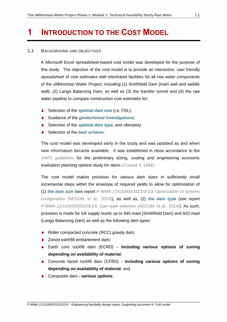
A Microsoft Excel spreadsheet-based cost model was developed for the purpose of
this study. The objective of the cost model is to provide an interactive, user friendly
spreadsheet of cost estimates with interlinked facilities for all raw water components
of the uMkhomazi Water Project, including (1) Smithfield Dam (main wall and saddle
wall), (2) Langa Balancing Dam, as well as (3) the transfer tunnel and (4) the raw
water pipeline to compare construction cost estimates for:
Selection of the optimal dam size (i.e. FSL);
Guidance of the geotechnical investigations;
Selection of the optimal dam type; and ultimately
Selection of the best scheme.
The cost model was developed early in the study and was updated as and when
new information became available. It was established in close accordance to the
VAPS guidelines for the preliminary sizing, costing and engineering economic
evaluation planning options study for dams (Consult 4, 1994).
The cost model makes provision for various dam sizes in sufficiently small
incremental steps within the envelope of required yields to allow for optimization of
(1) the dam size (see report P WMA 11/U10/00/3312/3/1/3: Optimization of scheme
configuration (AECOM, et al., 2014)), as well as, (2) the dam type (see report
P WMA 11/U10/00/3312/3/1/5: Dam type selection (AECOM, et al., 2014)). As such,
provision is made for full supply levels up to 940 masl (Smithfield Dam) and 923 masl
(Langa Balancing Dam) as well as the following dam types:
Roller compacted concrete (RCC) gravity dam;
Zoned earthfill embankment dam;
Earth core rockfill dam (ECRD) - including various options of zoning
depending on availability of material;
Concrete faced rockfill dam (CFRD) - including various options of zoning
depending on availability of material; and
Composite dam - various options.

The uMkhomazi Water Project Phase 1: Module 1: Technical Feasibility Study Raw Water 1-2
P WMA 11/U10/00/3312/3/1/4 – Engineering feasibility design report: Supporting document 4: Cost model
1.2 ORGANISATION OF THIS REPORT
This report forms part of the feasibility study on the uMkhomazi Water Project
Phase 1: Module 1: Technical Feasibility Study: Raw Water. More specifically, it
covers Task 5.17 (Creating a cost model for the project) as part of the Engineering
Investigations (Task 5). The Engineering Investigation main task consists of the tasks
shown in Table 1.1:
Table 1.1: Tasks within the Engineering Investigation task
Task number Task description
5.1 Optimization of conveyance system
5.2 Dam position
5.3 Materials investigation
5.4 Geomorphologic and seismic investigation
5.5 Geotechnical investigation
5.6 Survey
5.7 Dam type selection
5.8 Establish required capacity of dam
5.9 Flood and backwater calculations for the final dam
5.10 Climatological data for the construction site
5.11 Water quality and limnological review
5.12 Sediment yield
5.13 Land requirements and associated costs
5.14 Optimize scheme configuration
5.15 Assessment of the potential for hydropower
5.16 Feasibility design of the selected scheme
5.17 Creating a cost model for the project
The cost model was used in order to assist in the decision making and cost
estimation for the following tasks:
Task 5.1: Optimization of conveyance system;
Task 5.2: Dam position;
Task 5.7: Dam type selection;
Task 5.14: Optimisation of scheme;
Task 5.15: Assessment for the potential for hydropower;
Task 7: Institutional, operational and financial aspects; and
Task 8: Socio-economic analysis.

The uMkhomazi Water Project Phase 1: Module 1: Technical Feasibility Study Raw Water 1-3
P WMA 11/U10/00/3312/3/1/4 – Engineering feasibility design report: Supporting document 4: Cost model
The report is organised as follows:
Chapter 1 serves as an introduction to the report and provides the background
and objectives of the cost model.
Chapter 2 provides basic information on the cost model pertaining to the rates
and costs included in the model.
Chapter 3 gives an overview on the functioning of the cost model and presents
an overview of what can be expected in the user guide.
Chapter 4 provides a user guide explaining how the cost model must be
operated. It includes information on the process that needs to be followed in
order to ensure that all the required variable parameters are accurately inputted.
This chapter also provides an explanation on how to input the dam long section,
dimensions of the dam and the rates. In addition, it also provides information on
how to view the output results and what should be reviewed in order to provide
an accurate output.
Chapter 5 incorporates technical information giving a detailed explanation on
how the quantities for the various dam types are determined.

The uMkhomazi Water Project Phase 1: Module 1: Technical Feasibility Study Raw Water 2-1
P WMA 11/U10/00/3312/3/1/4 – Engineering feasibility design report: Supporting document 4: Cost model
2 BASIC INFORMATION ON THE COST MODEL
2.1 COSTS
The cost model takes into account the following direct costs within each of the major
system components as mentioned in Section 1:
Dam(s):
♦ Dam forming and excavation;
♦ Multi-level intake structure and outlet works;
♦ Side channel or ogee spillway(s) with chute; and
♦ Diversion works (including cofferdam(s), tunnel(s), intake and outlet portals);
Transfer tunnel;
♦ Intake structure (including intake tower, outlet works, stilling basin, bridge,
mechanical and electrical items, etc.);
♦ Portals, adits, ventilation shafts and tunnel excavations;
♦ Rock support, grouting and concrete linings; and
♦ Access roads.
Raw water pipeline;
♦ Excavations;
♦ Supply and laying of pipes; and
♦ Backfilling.
In addition the following costs are taken into consideration (the percentages shown in
brackets are set as a default in the model; they may however be adjusted):
Landscaping (5% of direct costs)
Miscellaneous (10% of direct costs)
Preliminary and general (30%)
Contingencies (10%)
Planning design and supervision (15%)
VAT (14%)
As the main objective of the cost model is to compare construction cost estimates,
and being common costs for all the different scheme-options, the following costs are
excluded from the cost model:
Roads (deviation of roads as well as access roads);
Electricity supply and deviation;

The uMkhomazi Water Project Phase 1: Module 1: Technical Feasibility Study Raw Water 2-2
P WMA 11/U10/00/3312/3/1/4 – Engineering feasibility design report: Supporting document 4: Cost model
Water to site;
Housing and accommodation;
Social (relocation) and environmental costs; and
Flow gauging weirs.
2.2 BILL OF QUANTITIES AND RATES FOR DAMS
The bill of quantities incorporated in the cost model for each of the different dam
types was based on that from the Vaal Augmentation Planning Study (VAPS)
(Consult 4, 1994) with a level of detail commensurate to a feasibility study.
For this purpose the latest rates from tenders for the various dam components
were obtained and incorporated into the cost model. Rates for (1) embankment-
forming materials, (2) excavation activities and (3) concrete are explained in
detail in the following sections.
2.2.1 Rates for embankment-forming materials
In accordance with the South African Bureau of Standards’ Standardized
Specification for Civil Engineering Construction DE: Small Earth Dams (South
African Bureau of Standards, 1984) rates included in the cost model for all
embankment forming-materials, i.e. (1) impervious fill, (2) semi pervious fill,
(3) rockfill, (4) rip-rap, (5) gravel and sand layer(s), (6) drains, (7) IVRCC, (8)
RCC, and (9) CVC sand, consist of the following costs:
Selection and delivery of material excavated; or
Excavating and selecting material from borrow pits in the designated borrow
areas; as well as
Haulage;
Spreading;
Adding water or drying;
Placing;
Compacting;
Grading in the relevant zones or parts of the embankment;
Stockpiling or processing, or both, where necessary; and
Final grading of borrow pits that are in the dam basin.
Rates adopted for embankment forming-materials are summarised in Table 2.1.

The uMkhomazi Water Project Phase 1: Module 1: Technical Feasibility Study Raw Water 2-3
P WMA 11/U10/00/3312/3/1/4 – Engineering feasibility design report: Supporting document 4: Cost model
Table 2.1: 2013 Rates adopted for embankment forming-materials
Item no Item description Rate
(R/m³)
Forming embankment
8.3.5
a) Core (impervious earthfill) 48.37
b) Upstream and downstream shells (semi pervious earthfill)
48.37
c) Rockfill (Impervious layer) 91.00
d) Rip-rap 438.52
e) Gravel layer 97.94
f) Sand layer transition zone 97.94
g) Blanket and chimney drains 789.45
h) IVRCC(1)
45.45
i) RCC concrete 1156.71
j) CVC concrete 1 981.85
(1) Per square metre of dam surface area
2.2.2 Rates for excavation activities
In accordance with the South African Bureau of Standards’ Standardized
Specification for Civil Engineering Construction DE: Small Earth Dams (South
African Bureau of Standards, 1984) rates included for all excavation activities
distinguished between the following:
Material from essential excavations, i.e. the embankment foundation
excavations, that is excavated and unsuitable for use in the embankments.
This rate covers the cost of excavation in all materials, removal to the
designated waste disposal site that was identified in the dam basin, spreading
and trimming.
Material from essential excavations, i.e. the embankment foundation
excavations, that is excavated and suitable for use in the embankments. This
rate covers the cost of excavation of the hole in all materials and trimming it
ready for further construction activity. This material might need to be stockpiled
for later use in a designated stockpile area. Provision is also made here for
excavation in intermediate and hard rock material.
Rates adopted for excavation activities are summarised in Table 2.2.

The uMkhomazi Water Project Phase 1: Module 1: Technical Feasibility Study Raw Water 2-4
P WMA 11/U10/00/3312/3/1/4 – Engineering feasibility design report: Supporting document 4: Cost model
Table 2.2: 2013 Rates adopted for excavation activities
Item no Item description Rate
(R/m³)
Excavation
8.3.3
a) Material unsuitable for embankment
(excavation, removal to designated waste disposal sites in the dam basin, spreading and trimming)
31.60
b) Material suitable for embankment from essential excavations
Stockpiled
(excavation , possible removal to stockpile areas, and trimming it ready for further construction activity)
30.30
c) Extra over items (b) for excavation in:
1) Intermediate material
2) Hard rock material
Included in 8.3.3 (a)
36.50
2.2.3 Rates for concrete
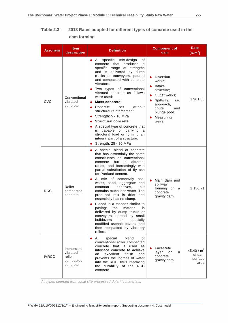
In accordance with the South African Bureau of Standards’ Standardized
Specification for Civil Engineering Construction DE: Small Earth Dams (South
African Bureau of Standards, 1984) rates adopted for the different types of
concrete used in the dam forming are summarised in Table 2.3.
The uMkhomazi Water Project Phase 1: Module 1: Technical Feasibility Study Raw Water 2-5
P WMA 11/U10/00/3312/3/1/4 – Engineering feasibility design report: Supporting document 4: Cost model
Table 2.3: 2013 Rates adopted for different types of concrete used in the
dam forming
Acronym Item
description Definition
Component of dam
Rate
(R/m3)
CVC Conventional vibrated concrete
A specific mix-design of concrete that produces a specific range of strengths and is delivered by dump trucks or conveyors, poured and compacted with concrete vibrators.
Two types of conventional vibrated concrete as follows were used:
Mass concrete:
Concrete set without structural reinforcement.
Strength: 5 - 10 MPa
Structural concrete:
A special type of concrete that is capable of carrying a structural load or forming an integral part of a structure.
Strength: 25 - 30 MPa
Diversion works;
Intake structure;
Outlet works;
Spillway, i.e. approach, chute and plunge pool;
Measuring weirs.
1 981.85
RCC Roller compacted concrete
A special blend of concrete that has essentially the same constituents as conventional concrete but in different ratios, and increasingly with partial substitution of fly ash for Portland cement.
A mix of cement/fly ash, water, sand, aggregate and common additives, but contains much less water. The produced mix is drier and essentially has no slump.
Placed in a manner similar to paving: the material is delivered by dump trucks or conveyors, spread by small bulldozers or specially modified asphalt pavers, and then compacted by vibratory rollers.
Main dam and spillway forming on a concrete gravity dam
1 156.71
IVRCC
Immersion- vibrated roller compacted concrete
A special blend of conventional roller compacted concrete that is used as interface concrete to achieve an excellent finish and prevents the ingress of water into the RCC, thus improving the durability of the RCC concrete.
Facecrete layer on a concrete gravity dam
45.40 / m2
of dam surface
area
All types sourced from local site processed doleritic materials.

The uMkhomazi Water Project Phase 1: Module 1: Technical Feasibility Study Raw Water 2-6
P WMA 11/U10/00/3312/3/1/4 – Engineering feasibility design report: Supporting document 4: Cost model
The rate for roller compacted concrete (RCC) included in Table 2.3 covers the
cost of (1) materials, (2) blasting and processing, (3) mixing, (4) transport,
(5) spreading and (6) compacting, as well as (7) other costs i.e. curing, water
pressure testing, etc.
The rate for conventional vibrated concrete (CVC) included in Table 2.3
covers the cost of (1) materials, (2) blasting and processing, (3) mixing, (4)
transport, (5) cooling and (6) vibration, as well as (7) other costs i.e. placing
labour, placing plant and joints cleaning, etc.
The uMkhomazi Water Project Phase 1: Module 1: Technical Feasibility Study Raw Water 3-1
P WMA 11/U10/00/3312/3/1/4 – Engineering feasibility design report: Supporting document 4: Cost model
3 FUNCTIONING OF THE COST MODEL
The cost model consists of a main input table that enables ease of movement
between the different input and output tables. The desired input and output tables are
opened by selecting the hyperlinks on the main input table.
The general steps that need to be followed with the cost model are as follows:
Step 1: Insert the long section of the dam;
Step 2: Select the required dam type(s);
Step 3: Choose the required components within the cost model;
Step 4: Change the variable parameters and rates;
Step 5: Observe the output results: Calculations, bill of quantities and summary
sheet.
Figure 3.1 summarises the flow of the input, calculations and output within the cost
model.

The uMkhomazi Water Project Phase 1: Module 1: Technical Feasibility Study Raw Water 3-2
P WMA 11/U10/00/3312/3/1/4 – Engineering feasibility design report: Supporting document 4: Cost model
Figure 3.1: Cost model flow diagram
The uMkhomazi Water Project Phase 1: Module 1: Technical Feasibility Study Raw Water 4-1
P WMA 11/U10/00/3312/3/1/4 – Engineering feasibility design report: Supporting document 4: Cost model
4 COST MODEL USER GUIDE
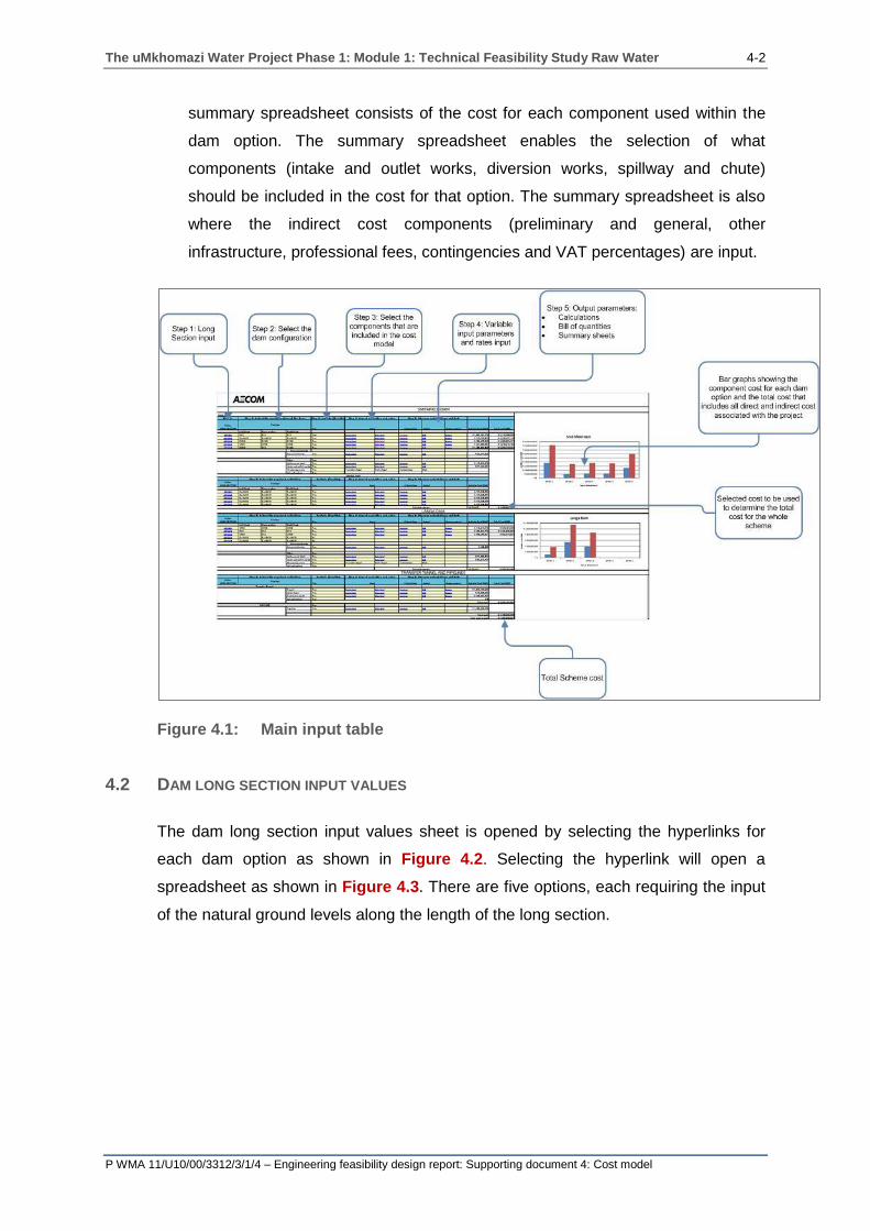
4.1 MAIN INPUT PANEL
The main input table enables the quick transition between different spreadsheets for
input of parameters and the observation of output values. Selecting a hyperlink will
take you to the required spreadsheet where data can be inputted or reviewed. As
shown in Figure 4.1, the information is input from the left to the right by selecting the
hyperlinks. In order to return to the main input table, select the AECOM logo. The
input occurs in the following order:
Step 1: Long section input: Selecting the hyperlink will open the long section
input spreadsheet whereby the natural ground level along the long section of the
dam is input including the excavation depth for each dam type. The headings
provide further explanation.
Step 2: Select the dam configuration (with the drop down arrows): The cost
model enables the selection of different dam types for the left flank, right flank
and river section of the dam. The position of the left and right flank is determined
by looking in a downstream direction.
Step 3: Select the components to be used within the dam model: Toggling the
selection arrow yes/no will either make the hyperlinks for the component visible
(therefore requiring input) or make them disappear, which would indicate that this
information does not need to be input. However, the exact components to be
used within each of the dam type options are further refined within the summary
sheet.
Step 4: Inputs – Variable input parameters and rates input: Selecting the
hyperlinks for each of the options will open the variable inputs table and rates
input table. If a hyperlink is selected and opens the same spreadsheet as was
opened for a previous option, it indicates that the same input values are used for
that option. This can be seen when selecting the rates input hyperlink for each
option. The same rates input table is used for each of the dam type options.
Step 5: Outputs: Calculations, bill of quantities, summary sheet. Selecting the
calculations hyperlink will open the calculation spreadsheet for that particular
option. This enables the review of the calculations. Selecting the bill of quantities
hyperlink opens the bill of quantities spreadsheet for that particular option; this
enables the review of the bill of quantities. Selecting the summary hyperlink for
that particular option opens the summary spreadsheet for the dam option; the
The uMkhomazi Water Project Phase 1: Module 1: Technical Feasibility Study Raw Water 4-2
P WMA 11/U10/00/3312/3/1/4 – Engineering feasibility design report: Supporting document 4: Cost model
summary spreadsheet consists of the cost for each component used within the
dam option. The summary spreadsheet enables the selection of what
components (intake and outlet works, diversion works, spillway and chute)
should be included in the cost for that option. The summary spreadsheet is also
where the indirect cost components (preliminary and general, other
infrastructure, professional fees, contingencies and VAT percentages) are input.
Figure 4.1: Main input table
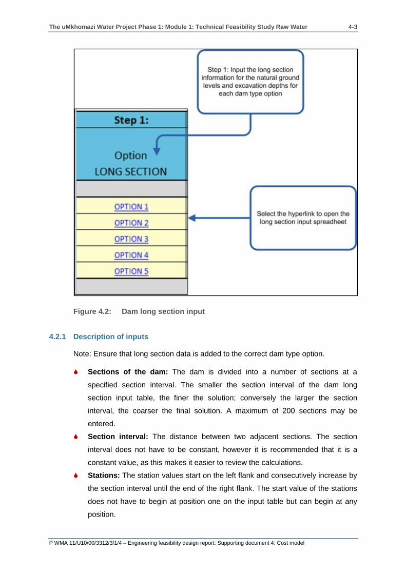
4.2 DAM LONG SECTION INPUT VALUES
The dam long section input values sheet is opened by selecting the hyperlinks for
each dam option as shown in Figure 4.2. Selecting the hyperlink will open a
spreadsheet as shown in Figure 4.3. There are five options, each requiring the input
of the natural ground levels along the length of the long section.
The uMkhomazi Water Project Phase 1: Module 1: Technical Feasibility Study Raw Water 4-3
P WMA 11/U10/00/3312/3/1/4 – Engineering feasibility design report: Supporting document 4: Cost model
Figure 4.2: Dam long section input
4.2.1 Description of inputs
Note: Ensure that long section data is added to the correct dam type option.
Sections of the dam: The dam is divided into a number of sections at a
specified section interval. The smaller the section interval of the dam long
section input table, the finer the solution; conversely the larger the section
interval, the coarser the final solution. A maximum of 200 sections may be
entered.
Section interval: The distance between two adjacent sections. The section
interval does not have to be constant, however it is recommended that it is a
constant value, as this makes it easier to review the calculations.
Stations: The station values start on the left flank and consecutively increase by
the section interval until the end of the right flank. The start value of the stations
does not have to begin at position one on the input table but can begin at any
position.

The uMkhomazi Water Project Phase 1: Module 1: Technical Feasibility Study Raw Water 4-4
P WMA 11/U10/00/3312/3/1/4 – Engineering feasibility design report: Supporting document 4: Cost model
Excavation option 2: The excavation depth for each section may be input for
both the shell excavation depth and the trench excavation depth. The depth from
the natural ground level to the required founding level is determined by means of
a geotechnical investigation. If this information is unknown, it may be left blank,
however it must be insured that excavation option 1 is selected in the variable
inputs table.
Figure 4.3: Long section input table
4.3 VARIABLE INPUT TABLE
The variable input table, as shown in Figure 4.4, is opened by selecting the hyperlink
for each particular option or dam component. By selecting the hyperlink the
spreadsheet pertaining to the required option will open, allowing easy input of the
variables. The variable input parameters include the dimensions of the dam types,
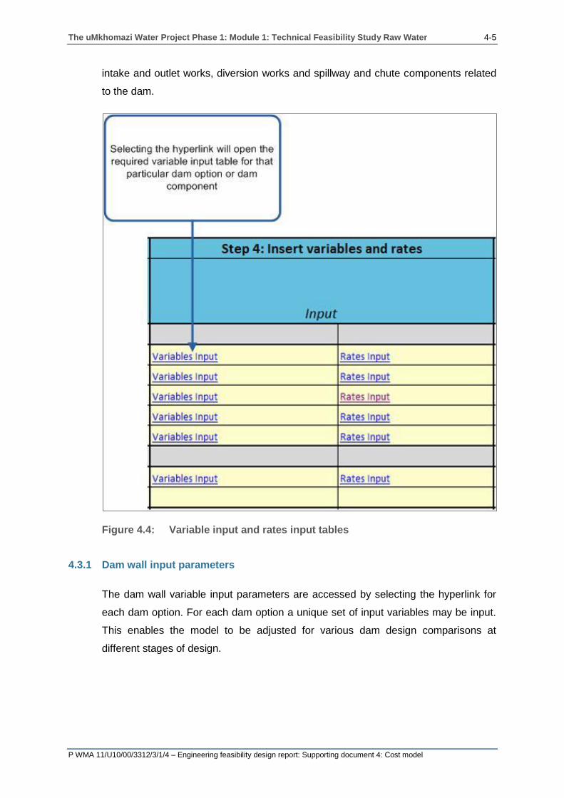
The uMkhomazi Water Project Phase 1: Module 1: Technical Feasibility Study Raw Water 4-5
P WMA 11/U10/00/3312/3/1/4 – Engineering feasibility design report: Supporting document 4: Cost model
intake and outlet works, diversion works and spillway and chute components related
to the dam.
Figure 4.4: Variable input and rates input tables
4.3.1 Dam wall input parameters
The dam wall variable input parameters are accessed by selecting the hyperlink for
each dam option. For each dam option a unique set of input variables may be input.
This enables the model to be adjusted for various dam design comparisons at
different stages of design.

The uMkhomazi Water Project Phase 1: Module 1: Technical Feasibility Study Raw Water 4-6
P WMA 11/U10/00/3312/3/1/4 – Engineering feasibility design report: Supporting document 4: Cost model
a) Roller compacted concrete dam
Figure 4.5 shows the exact position of each input variable on the dam cross
section, with Figure 4.6 showing the variable input table for the roller compacted
dam (RCC) type option.

The uMkhomazi Water Project Phase 1: Module 1: Technical Feasibility Study Raw Water 4-7
P WMA 11/U10/00/3312/3/1/4 – Engineering feasibility design report: Supporting document 4: Cost model
Figure 4.5: Roller compacted concrete dam variable inputs table

The uMkhomazi Water Project Phase 1: Module 1: Technical Feasibility Study Raw Water 4-8
P WMA 11/U10/00/3312/3/1/4 – Engineering feasibility design report: Supporting document 4: Cost model
Figure 4.6: Roller compacted variable input table
The uMkhomazi Water Project Phase 1: Module 1: Technical Feasibility Study Raw Water 4-9
P WMA 11/U10/00/3312/3/1/4 – Engineering feasibility design report: Supporting document 4: Cost model
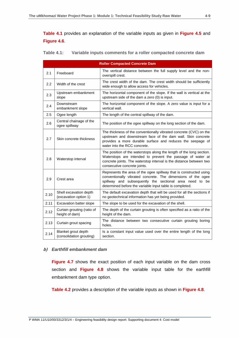
Table 4.1 provides an explanation of the variable inputs as given in Figure 4.5 and
Figure 4.6.
Table 4.1: Variable inputs comments for a roller compacted concrete dam
Roller Compacted Concrete Dam
2.1 Freeboard The vertical distance between the full supply level and the non-
overspill crest.
2.2 Width of the crest The crest width of the dam. The crest width should be sufficiently
wide enough to allow access for vehicles.
2.3 Upstream embankment
slope
The horizontal component of the slope. If the wall is vertical at the
upstream side of the dam a zero (0) is input.
2.4 Downstream
embankment slope
The horizontal component of the slope. A zero value is input for a
vertical wall.
2.5 Ogee length The length of the central spillway of the dam.
2.6 Central chainage of the
ogee spillway The position of the ogee spillway on the long section of the dam.
2.7 Skin concrete thickness
The thickness of the conventionally vibrated concrete (CVC) on the
upstream and downstream face of the dam wall. Skin concrete
provides a more durable surface and reduces the seepage of
water into the RCC concrete.
2.8 Waterstop interval
The position of the waterstops along the length of the long section.
Waterstops are intended to prevent the passage of water at
concrete joints. The waterstop interval is the distance between two
consecutive concrete joints.
2.9 Crest area
Represents the area of the ogee spillway that is constructed using
conventionally vibrated concrete. The dimensions of the ogee
spillway and subsequently the sectional area need to be
determined before the variable input table is completed.
2.10 Shell excavation depth
(excavation option 1)
The default excavation depth that will be used for all the sections if
no geotechnical information has yet being provided.
2.11 Excavation batter slope The slope to be used for the excavation of the shell.
2.12 Curtain grouting (ratio of
height of dam)
The depth of the curtain grouting is often specified as a ratio of the
height of the dam.
2.13 Curtain grout spacing The distance between two consecutive curtain grouting boring
holes.
2.14 Blanket grout depth
(consolidation grouting)
Is a constant input value used over the entire length of the long
section.
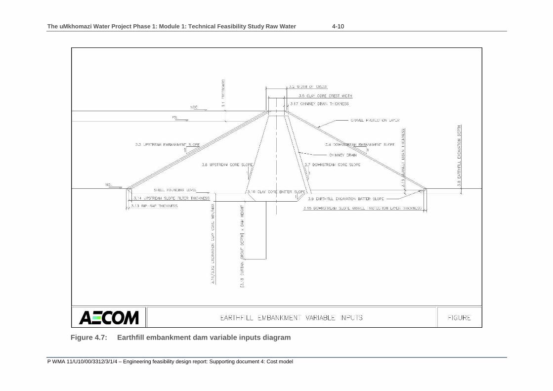
b) Earthfill embankment dam
Figure 4.7 shows the exact position of each input variable on the dam cross
section and Figure 4.8 shows the variable input table for the earthfill
embankment dam type option.
Table 4.2 provides a description of the variable inputs as shown in Figure 4.8.
The uMkhomazi Water Project Phase 1: Module 1: Technical Feasibility Study Raw Water 4-10
P WMA 11/U10/00/3312/3/1/4 – Engineering feasibility design report: Supporting document 4: Cost model
Figure 4.7: Earthfill embankment dam variable inputs diagram

The uMkhomazi Water Project Phase 1: Module 1: Technical Feasibility Study Raw Water 4-11
P WMA 11/U10/00/3312/3/1/4 – Engineering feasibility design report: Supporting document 4: Cost model
Figure 4.8: Earthfill embankment dam variable inputs table

The uMkhomazi Water Project Phase 1: Module 1: Technical Feasibility Study Raw Water 4-12
P WMA 11/U10/00/3312/3/1/4 – Engineering feasibility design report: Supporting document 4: Cost model
Table 4.2: Variable inputs comments for an earthfill embankment dam
Earthfill Embankment Dam
3.1 Freeboard The vertical distance between the non-overspill crest and the full
supply level.
3.2 Width of the crest The crest width of the dam. The crest width should be sufficiently
wide enough to allow access for vehicles.
3.3 Upstream embankment
slope
The horizontal component of the slope. If the wall is vertical at
the upstream side of the dam a zero (0) is input.
3.4 Downstream embankment
slope
The horizontal component of the slope. If the wall is vertical at
the upstream side of the dam, a zero (0) is input.
3.5 Clay core crest width The width of the crest of the clay core. The width of the clay core
crest should be less than the width of the dam crest.
3.6 Upstream core slope
The horizontal component of the slope of the internal clay core.
If the core is vertical at the upstream side of the dam a zero (0)
is input.
3.7 Downstream core slope
The horizontal component of the slope of the internal clay core.
If the core is vertical at the downstream side of the dam a zero
(0) is input.
3.8 Earthfill excavation depth
The default excavation depth that will be used for all of the
sections if no geotechnical information has yet being provided. If
excavation option 1 is selected.
3.9 Earthfill excavation batter
slope The slope to be used for the excavation of the shell.
3.10 Clay core batter slope The slope to be used for the excavation of the clay core trench.
3.11 Excavation clay core (max) The maximum depth the clay core is excavated if excavation
option 1 is selected.
3.12 Excavation clay core (min) The minimum depth the clay core is excavated if excavation
option 1 is selected.
3.13 Rip-rap thickness The horizontal width of the rip-rap layer.
3.14 Upstream slope filter
thickness
The horizontal width of the upstream slope filter between the
shell earthfill material and the rip-rap layer.
3.15 Downstream slope gravel
protection layer The horizontal width of the downstream gravel protection layer.
3.16 Blanket drain thickness The vertical thickness of the blanket drain.
3.17 Chimney drain thickness The horizontal width of the chimney drain on the downstream
face of the clay core.
3.18
Curtain grout depth:
Proportion of the dam
height
The depth of the curtain grouting is specified as a ratio of the
height of the dam.
3.19 Blanket grout depth
(consolidation grouting)
A constant input value used over the entire length of the long
section.
3.20 Grout spacing The distance between two consecutive curtain grouting boring
holes.
The uMkhomazi Water Project Phase 1: Module 1: Technical Feasibility Study Raw Water 4-13
P WMA 11/U10/00/3312/3/1/4 – Engineering feasibility design report: Supporting document 4: Cost model
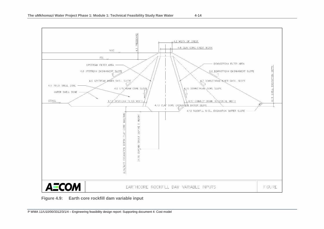
c) Earth core rockfill dam
Figure 4.9 displays the exact position of each input variable on the dam cross
section, with Figure 4.10 showing the variable input table for the earth core
rockfill embankment dam type option.
Table 4.3 provides a description of the variable inputs as shown in Figure 4.10.
The uMkhomazi Water Project Phase 1: Module 1: Technical Feasibility Study Raw Water 4-14
P WMA 11/U10/00/3312/3/1/4 – Engineering feasibility design report: Supporting document 4: Cost model
Figure 4.9: Earth core rockfill dam variable input

The uMkhomazi Water Project Phase 1: Module 1: Technical Feasibility Study Raw Water 4-15
P WMA 11/U10/00/3312/3/1/4 – Engineering feasibility design report: Supporting document 4: Cost model
Figure 4.10: Earth core rockfill dam variable inputs table
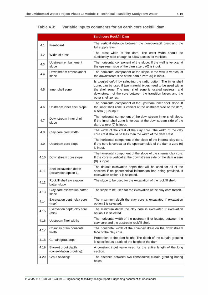
The uMkhomazi Water Project Phase 1: Module 1: Technical Feasibility Study Raw Water 4-16
P WMA 11/U10/00/3312/3/1/4 – Engineering feasibility design report: Supporting document 4: Cost model
Table 4.3: Variable inputs comments for an earth core rockfill dam
Earth core Rockfill Dam
4.1 Freeboard The vertical distance between the non-overspill crest and the
full supply level.
4.2 Width of crest The crest width of the dam. The crest width should be
sufficiently wide enough to allow access for vehicles.
4.3 Upstream embankment
slope
The horizontal component of the slope. If the wall is vertical at
the upstream side of the dam a zero (0) is input.
4.4 Downstream embankment
slope
The horizontal component of the slope. If the wall is vertical at
the downstream side of the dam a zero (0) is input.
4.5 Inner shell zone
Is toggled on/off by selecting the radio button. The inner shell
zone, can be used if two material types need to be used within
the shell zone. The inner shell zone is located upstream and
downstream of the core between the transition layers and the
outer shell zones.
4.6 Upstream inner shell slope
The horizontal component of the upstream inner shell slope. If
the inner shell zone is vertical at the upstream side of the dam,
a zero (0) is input.
4.7 Downstream inner shell
slope
The horizontal component of the downstream inner shell slope.
If the inner shell zone is vertical at the downstream side of the
dam, a zero (0) is input.
4.8 Clay core crest width The width of the crest of the clay core. The width of the clay
core crest should be less than the width of the dam crest.
4.9 Upstream core slope
The horizontal component of the slope of the internal clay core.
If the core is vertical at the upstream side of the dam a zero (0)
is input.
4.10 Downstream core slope
The horizontal component of the slope of the internal clay core.
If the core is vertical at the downstream side of the dam a zero
(0) is input.
4.11 Shell excavation depth
(excavation option 1)
The default excavation depth that will be used for all of the
sections if no geotechnical information has being provided. If
excavation option 1 is selected.
4.12 Rockfill shell excavation
batter slope
The slope to be used for the excavation of the rockfill shell.
4.13 Clay core excavation batter
slope
The slope to be used for the excavation of the clay core trench.
4.14 Excavation depth clay core
(max)
The maximum depth the clay core is excavated if excavation
option 1 is selected.
4.15 Excavation depth clay core
(min)
The minimum depth the clay core is excavated if excavation
option 1 is selected.
4.16 Upstream filter width: The horizontal width of the upstream filter located between the
clay core and the upstream rockfill shell.
4.17 Chimney drain horizontal
width
The horizontal width of the chimney drain on the downstream
face of the clay core.
4.18 Curtain grout depth Proportion of the dam height: The depth of the curtain grouting
is specified as a ratio of the height of the dam
4.19 Blanket grout depth
(consolidation grouting):
A constant input value used for the entire length of the long
section.
4.20 Grout spacing: The distance between two consecutive curtain grouting boring
holes.

The uMkhomazi Water Project Phase 1: Module 1: Technical Feasibility Study Raw Water 4-17
P WMA 11/U10/00/3312/3/1/4 – Engineering feasibility design report: Supporting document 4: Cost model
d) Concrete faced rockfill dam
Figure 4.11 shows the variable input table for the concrete faced rockfill
embankment type option, with Figure 4.12 showing the exact position of each
input variable on the dam cross section.
Table 4.4 provides a description of the variable inputs as shown in Figure 4.12.

The uMkhomazi Water Project Phase 1: Module 1: Technical Feasibility Study Raw Water 4-18
P WMA 11/U10/00/3312/3/1/4 – Engineering feasibility design report: Supporting document 4: Cost model
Figure 4.11: Concrete faced rockfill dam diagram

The uMkhomazi Water Project Phase 1: Module 1: Technical Feasibility Study Raw Water 4-19
P WMA 11/U10/00/3312/3/1/4 – Engineering feasibility design report: Supporting document 4: Cost model
Figure 4.12: Concrete faced rockfill dam variable input table

The uMkhomazi Water Project Phase 1: Module 1: Technical Feasibility Study Raw Water 4-20
P WMA 11/U10/00/3312/3/1/4 – Engineering feasibility design report: Supporting document 4: Cost model
Table 4.4: Variable inputs comments for a concrete faced rockfill dam
Concrete Faced Rockfill Dam
5.1 Freeboard The vertical distance between the non-overspill crest and the
full supply level.
5.2 Width of crest The crest width of the dam. The crest width should be
sufficiently wide enough to allow access for vehicles.
5.3 Upstream slope The horizontal component of the slope. If the wall is vertical at
the upstream side of the dam a zero (0) is input.
5.4 Downstream slope The horizontal component of the slope. If the wall is vertical at
the downstream side of the dam a zero (0) is input.
5.5 Toe rockfill zone
Is toggled on/off by selecting the radio button. If two different
materials need to be used in the dam shell, a triangular toe
section may be included in the dam.
5.6 Internal zone upstream slope The slope of the upstream side of the toe rockfill zone.
5.7 Distance between NOC and
the top of the toe section
The vertical distance between the non-overspill crest and the
top of the toe rockfill zone.
5.8 Shell excavation depth
The default excavation depth that will be used for all of the
sections if no geotechnical information has being provided. If
excavation option 1 is selected.
5.9 Shell excavation batter slope The slope to be used for the excavation of the rockfill shell.
5.11 Plinth excavation batter
slope
The slope to be used for the excavation of the plinth.
5.12 Rockfill under excavation
width
The length of the plinth excavation trench extension into the
dam wall. The length starts at the upstream toe of the
concrete slab and continues downstream of the upstream toe.
5.13 Facecrete width at plinth The horizontal width of the facecrete slab at the plinth of the
dam.
5.14 Facecrete width at crest The horizontal width of the facecrete slab at the crest of the
dam.
5.15 Plinth width The horizontal width of the plinth.
5.16 Plinth thickness The vertical thickness of the plinth.
5.17 Gravel transition layer
thickness
The total horizontal width of the two gravel transition layers
located between the rockfill shell and the facecrete concrete
slab.
5.18 Curtain grout spacing The distance between two consecutive curtain grouting boring
holes.
5.19 Bottom blanket drain
thickness
The vertical thickness of the blanket drain. This input only
relates to the use of a toe rockfill zone.
5.20 Ratio of height to grout depth The depth of the curtain grouting is specified as a ratio of the
height of the dam.
5.21 Downstream gravel
protection layer
Is toggled on/off by selecting the radio button. If a
downstream rockfill layer is required.
5.22 Downstream gravel
protection layer width
The horizontal width of the downstream gravel protection
layer.
The uMkhomazi Water Project Phase 1: Module 1: Technical Feasibility Study Raw Water 4-21
P WMA 11/U10/00/3312/3/1/4 – Engineering feasibility design report: Supporting document 4: Cost model
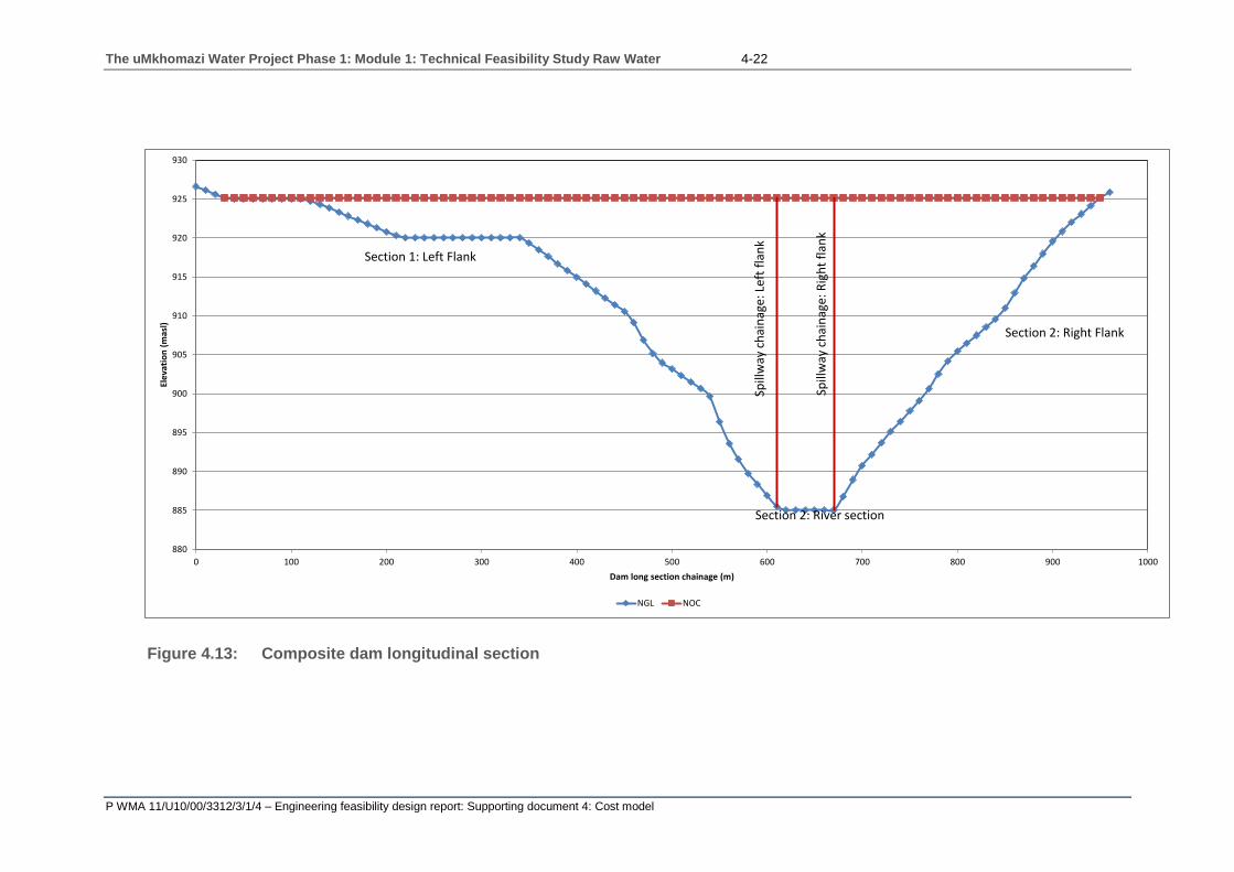
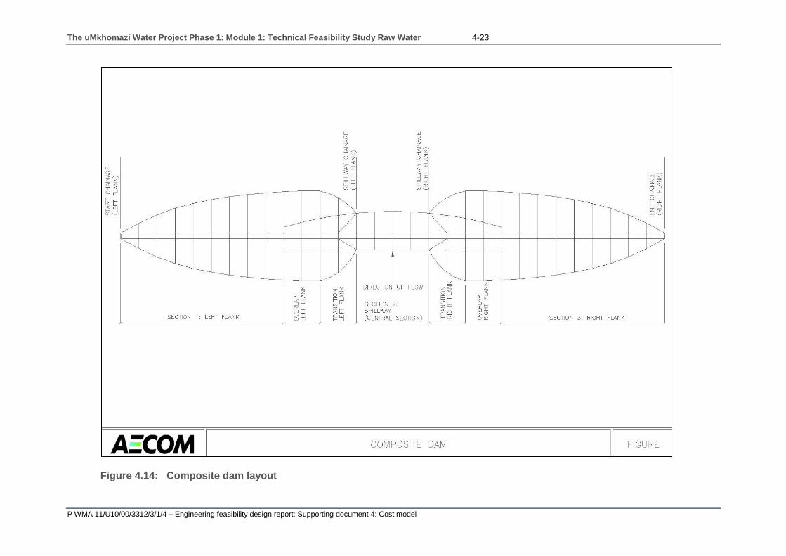
e) Composite dam
The cost model also enables the input of composite dam designs. The most
common composite dam structure is one that consists of a concrete gravity
central spillway section with an earth core rockfill embankment, earthfill
embankment or concrete faced rockfill left and right flank (see Figure 4.13 and
Figure 4.14). For this reason the cost model has been set up for the input of only
this type of composite structure. Other combinations may be used; however
there may be inconsistences in the transitions from one dam type to another.
In the cost model the position of the spillway is input and the lengths of transition
and overlap lengths may be input. The transition and overlap zones extend into
the left and right earthfill embankment sections.
The variables as described previously will be applicable to this section.
The uMkhomazi Water Project Phase 1: Module 1: Technical Feasibility Study Raw Water 4-22
P WMA 11/U10/00/3312/3/1/4 – Engineering feasibility design report: Supporting document 4: Cost model
Figure 4.13: Composite dam longitudinal section
880
885
890
895
900
905
910
915
920
925
930
0 100 200 300 400 500 600 700 800 900 1000
Ele
vati
on
(m
asl)
Dam long section chainage (m)
NGL NOC
Section 1: Left Flank
Section 2: River section
Section 2: Right Flank
Spill
way
chai
nag
e: L
eft
flan
k
Spill
way
chai
nag
e: R
igh
t fl
ank
The uMkhomazi Water Project Phase 1: Module 1: Technical Feasibility Study Raw Water 4-23
P WMA 11/U10/00/3312/3/1/4 – Engineering feasibility design report: Supporting document 4: Cost model
Figure 4.14: Composite dam layout

The uMkhomazi Water Project Phase 1: Module 1: Technical Feasibility Study Raw Water 4-24
P WMA 11/U10/00/3312/3/1/4 – Engineering feasibility design report: Supporting document 4: Cost model
4.3.2 Diversion works
This provision is necessary to permit construction to proceed in dry conditions.
An outlet tunnel or culvert may be temporarily adapted for this purpose during
construction, and subsequently employed as a discharge facility for the
completed dam. In order to transfer the flow into the tunnel, the construction of
temporary upstream and downstream cofferdams will need to be constructed as
shown in Figure 4.15 (Novak, Moffat et. Al, 2007).
Figure 4.15: Layout of diversion works (Novak, Moffat et. Al, 2007).
a) Cofferdam
Cofferdams are temporary structures used to divert water from an area where a
permanent structure has to be constructed. They must be as water tight as
practicable, relatively cheap and, if possible, constructed of locally available
materials (Novak, Moffat et. Al, 2007).
The cost model makes provision for the input of two soilcrete cofferdams, an
upstream and a downstream cofferdam. For both the upstream and downstream
cofferdams, a long section of station values and their corresponding natural
ground level elevations is required as input. The station input and the station
interval (the difference between two station values) does not have to be the
same but it is recommended to ensure consistency and ease of calculations.
Therefore the station values should increment by a constant station value.
The uMkhomazi Water Project Phase 1: Module 1: Technical Feasibility Study Raw Water 4-25
P WMA 11/U10/00/3312/3/1/4 – Engineering feasibility design report: Supporting document 4: Cost model
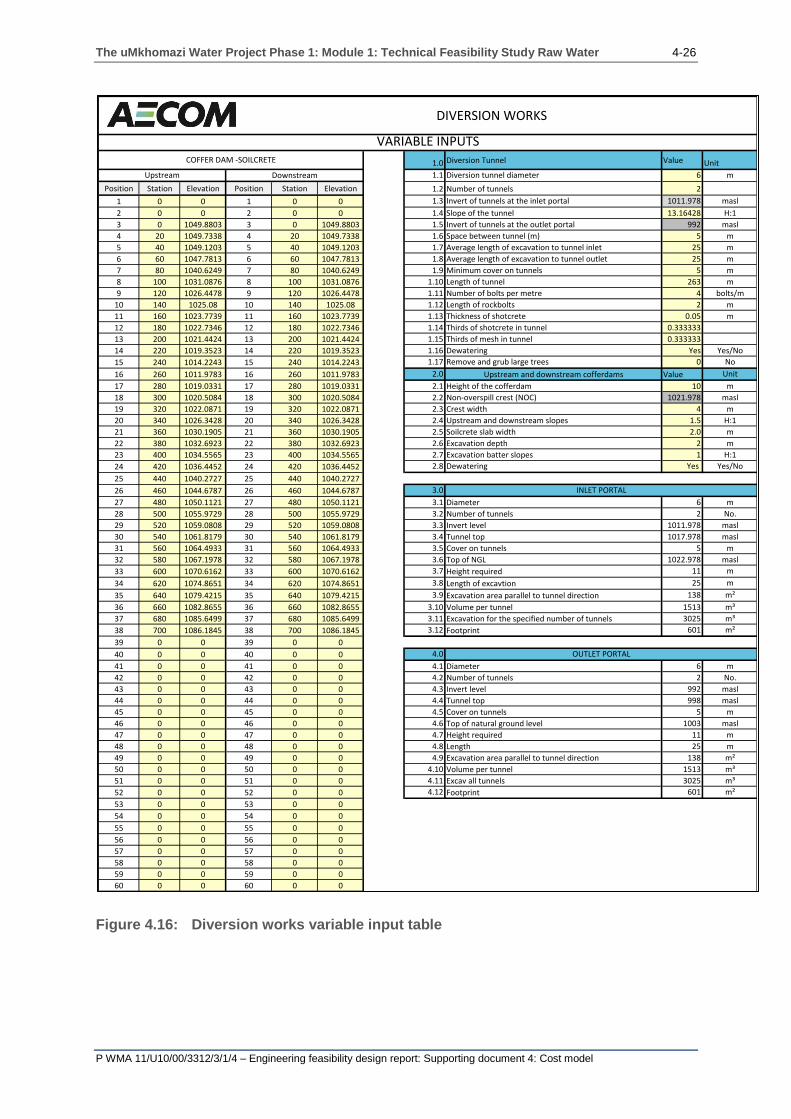
b) Diversion tunnel variable input
Figure 4.16 shows the long section input and variable inputs table for the
diversion works at Smithfield dam. The diversion works entails the construction
of soilcrete cofferdams at the upstream and downstream sides of the main dam.
Tunnels are bored through the left or right flank in order to divert the water to
provide a dry area for the construction of the main dam wall.
Figure 4.17 and Figure 4.18 provide schemetic presentations of the dam inlet
portal and diversion tunnels.
The uMkhomazi Water Project Phase 1: Module 1: Technical Feasibility Study Raw Water 4-26
P WMA 11/U10/00/3312/3/1/4 – Engineering feasibility design report: Supporting document 4: Cost model
Figure 4.16: Diversion works variable input table
1.0 Diversion Tunnel Value Unit
1.1 Diversion tunnel diameter 6 m
Position Station Elevation Position Station Elevation 1.2 Number of tunnels 2
1 0 0 1 0 0 1.3 Invert of tunnels at the inlet portal 1011.978 masl
2 0 0 2 0 0 1.4 Slope of the tunnel 13.16428 H:1
3 0 1049.8803 3 0 1049.8803 1.5 Invert of tunnels at the outlet portal 992 masl
4 20 1049.7338 4 20 1049.7338 1.6 Space between tunnel (m) 5 m
5 40 1049.1203 5 40 1049.1203 1.7 Average length of excavation to tunnel inlet 25 m
6 60 1047.7813 6 60 1047.7813 1.8 Average length of excavation to tunnel outlet 25 m
7 80 1040.6249 7 80 1040.6249 1.9 Minimum cover on tunnels 5 m
8 100 1031.0876 8 100 1031.0876 1.10 Length of tunnel 263 m
9 120 1026.4478 9 120 1026.4478 1.11 Number of bolts per metre 4 bolts/m
10 140 1025.08 10 140 1025.08 1.12 Length of rockbolts 2 m
11 160 1023.7739 11 160 1023.7739 1.13 Thickness of shotcrete 0.05 m
12 180 1022.7346 12 180 1022.7346 1.14 Thirds of shotcrete in tunnel 0.333333
13 200 1021.4424 13 200 1021.4424 1.15 Thirds of mesh in tunnel 0.333333
14 220 1019.3523 14 220 1019.3523 1.16 Dewatering Yes Yes/No
15 240 1014.2243 15 240 1014.2243 1.17 Remove and grub large trees 0 No
16 260 1011.9783 16 260 1011.9783 2.0 Upstream and downstream cofferdams Value Unit
17 280 1019.0331 17 280 1019.0331 2.1 Height of the cofferdam 10 m
18 300 1020.5084 18 300 1020.5084 2.2 Non-overspill crest (NOC) 1021.978 masl
19 320 1022.0871 19 320 1022.0871 2.3 Crest width 4 m
20 340 1026.3428 20 340 1026.3428 2.4 Upstream and downstream slopes 1.5 H:1
21 360 1030.1905 21 360 1030.1905 2.5 Soilcrete slab width 2.0 m
22 380 1032.6923 22 380 1032.6923 2.6 Excavation depth 2 m
23 400 1034.5565 23 400 1034.5565 2.7 Excavation batter slopes 1 H:1
24 420 1036.4452 24 420 1036.4452 2.8 Dewatering Yes Yes/No
25 440 1040.2727 25 440 1040.2727
26 460 1044.6787 26 460 1044.6787 3.0
27 480 1050.1121 27 480 1050.1121 3.1 Diameter 6 m
28 500 1055.9729 28 500 1055.9729 3.2 Number of tunnels 2 No.
29 520 1059.0808 29 520 1059.0808 3.3 Invert level 1011.978 masl
30 540 1061.8179 30 540 1061.8179 3.4 Tunnel top 1017.978 masl
31 560 1064.4933 31 560 1064.4933 3.5 Cover on tunnels 5 m
32 580 1067.1978 32 580 1067.1978 3.6 Top of NGL 1022.978 masl
33 600 1070.6162 33 600 1070.6162 3.7 Height required 11 m
34 620 1074.8651 34 620 1074.8651 3.8 Length of excavtion 25 m
35 640 1079.4215 35 640 1079.4215 3.9 Excavation area parallel to tunnel direction 138 m²
36 660 1082.8655 36 660 1082.8655 3.10 Volume per tunnel 1513 m³
37 680 1085.6499 37 680 1085.6499 3.11 Excavation for the specified number of tunnels 3025 m³
38 700 1086.1845 38 700 1086.1845 3.12 Footprint 601 m²
39 0 0 39 0 0
40 0 0 40 0 0 4.0
41 0 0 41 0 0 4.1 Diameter 6 m
42 0 0 42 0 0 4.2 Number of tunnels 2 No.
43 0 0 43 0 0 4.3 Invert level 992 masl
44 0 0 44 0 0 4.4 Tunnel top 998 masl
45 0 0 45 0 0 4.5 Cover on tunnels 5 m
46 0 0 46 0 0 4.6 Top of natural ground level 1003 masl
47 0 0 47 0 0 4.7 Height required 11 m
48 0 0 48 0 0 4.8 Length 25 m
49 0 0 49 0 0 4.9 Excavation area parallel to tunnel direction 138 m²
50 0 0 50 0 0 4.10 Volume per tunnel 1513 m³
51 0 0 51 0 0 4.11 Excav all tunnels 3025 m³
52 0 0 52 0 0 4.12 Footprint 601 m²
53 0 0 53 0 0
54 0 0 54 0 0
55 0 0 55 0 0
56 0 0 56 0 0
57 0 0 57 0 0
58 0 0 58 0 0
59 0 0 59 0 0
60 0 0 60 0 0
INLET PORTAL
OUTLET PORTAL
DownstreamUpstream
VARIABLE INPUTSCOFFER DAM -SOILCRETE
DIVERSION WORKS

The uMkhomazi Water Project Phase 1: Module 1: Technical Feasibility Study Raw Water 4-27
P WMA 11/U10/00/3312/3/1/4 – Engineering feasibility design report: Supporting document 4: Cost model
Figure 4.17: Inlet portal and diversion tunnels
Figure 4.18: Schematic representation of dam inlet and diversion tunnels

The uMkhomazi Water Project Phase 1: Module 1: Technical Feasibility Study Raw Water 4-28
P WMA 11/U10/00/3312/3/1/4 – Engineering feasibility design report: Supporting document 4: Cost model
Table 4.5 and Table 4.6 provide descriptions of the variable inputs, as shown in
Figure 4.16, for the diversion tunnels and the upstream and downstream cofferdams
respectively.
Table 4.5: Diversion tunnels variable input
Diversion tunnels
1.1 Diversion tunnel diameter The diameter of the diversion tunnels that will be running
from the inlet portal to the outlet portal.
1.2 Number of tunnels The number of tunnels required to pass the required
design flood.
1.3 Invert of tunnels at the inlet
portal
The invert level of the tunnel that also refers to the bottom
level of the tunnel and inlet portal.
1.4 Slope of the tunnel
The required downward slope of the tunnel. Entered as a
positive value and the horizontal component of the slope
is an input.
1.5 Invert of tunnels at the outlet
portal
(Calculated or read only) The invert level of the tunnel at
the outward portal that is calculated using the slope of the
tunnel and the invert level of the inlet portal.
1.6 Space between the tunnels The space required between the tunnels.
1.7 Average length of excavation to
tunnel inlet
The distance from the daylight point at the invert level to
the point at which the excavation of the tunnel will
commence.
1.8 Average length of excavation to
tunnel outlet
The distance from the daylight point at the invert level to
the point at which the excavation of the tunnel will stop.
1.9 Minimum cover on tunnels The minimum cover required for the tunnel or the distance
between the top of the tunnel and the natural ground level.
1.10 Length of tunnel: The distance between the inlet portal of the tunnel and the
outlet portal.
1.11 Number of bolts per metre of
tunnel
The number of 25mm diameter bolts required per linear
metre of tunnel that depends on the tunnel diameter and
rock support class. Refer to Table 4.19.
1.12 Length of rockbolts The lengths of the bolts used to secure the tunnel lining.
1.13 Thickness of shotcrete The thickness perpendicular to the tunnel surface.
1.14 Thirds of shotcrete in tunnel
Depending on the class of bolting, only certain sections of
the tunnel circumference require shotcrete (refer to Table
4.18 and Table 4.19).
Class I and II – zero shotcrete is required;
Class III and IV – top 120 degress require shotcrete;
Class V – the top 180 degrees require shotcrete;
Class VI – entire circumference requires shotcrete.
1.15 Thirds of mesh in tunnel As in 1.14 above; the sections being grouted require
mesh.
1.16 Dewatering
Select Yes/No by clicking on the radio button. Indicate
whether dewatering needs to be included in the final cost
or not. Dewatering is input as a sum in the rates input
table.
1.17 Remove and grub large trees The number of trees that need to be removed and
grubbed.

The uMkhomazi Water Project Phase 1: Module 1: Technical Feasibility Study Raw Water 4-29
P WMA 11/U10/00/3312/3/1/4 – Engineering feasibility design report: Supporting document 4: Cost model
Table 4.6: Upstream and downstream cofferdams variable input
Upstream and downstream cofferdams
2.1 Height of the
cofferdam
The difference in height between the NOC of the cofferdam and the
natural ground level in the centre of the river.
2.2
Non-overspill crest
(NOC) (calculated
or read only)
Calculated by taking the lowest natural ground level in the centre of the
river bank and adding the height of the cofferdam.
2.3 Crest width The width of the crest of the cofferdam.
2.4 Upstream and
downstream slopes
The upstream and downstream slopes of the cofferdam. The horizontal
component of the slopes is the input parameter.
2.5 Soilcrete slab width The horizontal section width of the soilcrete slab within the upstream
and downstream cofferdams.
2.6 Excavation depth The depth of excavation required in order to reach the required
founding level. The same excavation depth is used for all the sections.
2.7 Excavation batter
slopes
The batter slopes required for the excavation of the cofferdam
foundations. The horizontal component of the slope is input.
2.8 Dewatering Indicate, by selecting the Yes/No radio button, whether dewatering is
required for the upstream and downstream cofferdams.
4.3.3 Spillway and chute input parameters
Dams require certain ancillary structures and facilities to enable them to discharge
their operational function safely and effectively. In particular, adequate provision must
be made for the safe passage of extreme floods and for the controlled draw-off and
discharge of water in fulfilment of the purpose of the reservoir. Spillways and outlet
works are therefore essential features (Novak, Moffat et al., 2007).
The purpose of the spillway is to pass flood water, and in particular the design flood,
safely downstream when the reservoir is overflowing. It has two principal
components: the controlling spill weir and the spillway channel. The purpose of the
latter being is to conduct flood flows safely downstream of the dam. The latter must
incorporate a stilling basin or other energy-dissipating device. The spillway capacity
must safely accommodate the safety evaluation flood, with the spillway level dictating
the maximum retention level of the dam, i.e. the full supply level (FSL) (Novak, Moffat
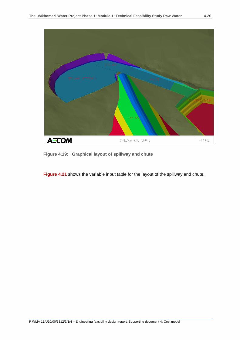
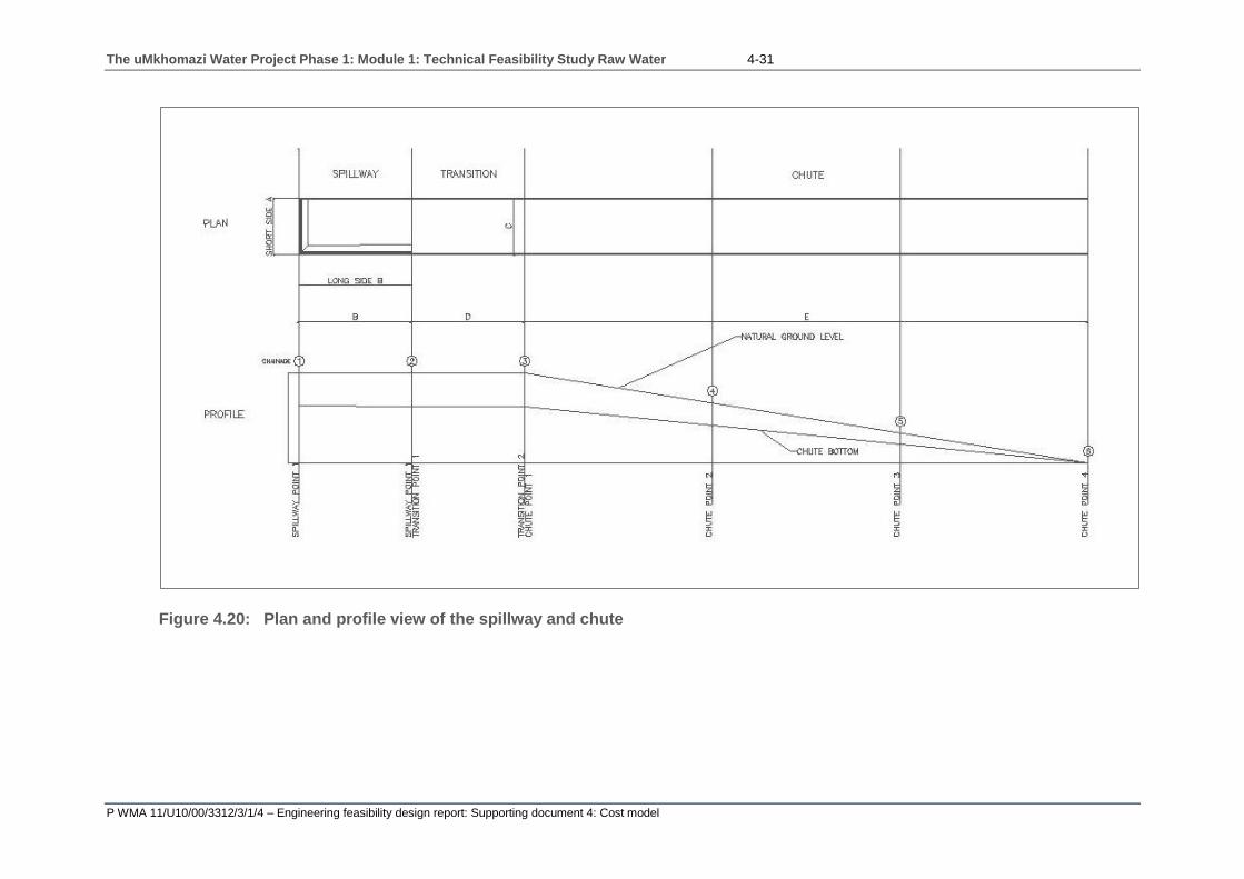
et al., 2007). Figure 4.19 shows the position of the spillway and chute in relation to
the dam wall and Figure 4.20 the plan and profile view thereof.
The uMkhomazi Water Project Phase 1: Module 1: Technical Feasibility Study Raw Water 4-30
P WMA 11/U10/00/3312/3/1/4 – Engineering feasibility design report: Supporting document 4: Cost model
Figure 4.19: Graphical layout of spillway and chute
Figure 4.21 shows the variable input table for the layout of the spillway and chute.
The uMkhomazi Water Project Phase 1: Module 1: Technical Feasibility Study Raw Water 4-31
P WMA 11/U10/00/3312/3/1/4 – Engineering feasibility design report: Supporting document 4: Cost model
Figure 4.20: Plan and profile view of the spillway and chute

The uMkhomazi Water Project Phase 1: Module 1: Technical Feasibility Study Raw Water 4-32
P WMA 11/U10/00/3312/3/1/4 – Engineering feasibility design report: Supporting document 4: Cost model
Figure 4.21: Spillway and chute variable input table

The uMkhomazi Water Project Phase 1: Module 1: Technical Feasibility Study Raw Water 4-33
P WMA 11/U10/00/3312/3/1/4 – Engineering feasibility design report: Supporting document 4: Cost model
Table 4.7 to Table 4.12 provides descriptions of the variable inputs, as shown in
Figure 4.21, for the spillway and chute, ogee design and the chute design.
Table 4.7: Spillway and chute variable input components
Spillway and chute
1.1 FSL Full supply level of the dam.
1.2 Qsef The safety evaluation flood for the dam.
1.3 Spillway and chute
excavation slope The batter slopes for the spillway and chute excavations.
Table 4.8: Spillway variable input components
Spillway
2.1 Co Discharge coefficient for the ogee design.
2.2 Ogee length The length of the spillway ( 𝑄 = 𝐶. 𝑳. 𝐻3
2 ) .
2.3 Ogee slope The downstream slope of the ogee spillway.
2.4 Upstream slope The spillway slope.
2.5 Spillway and chute
wall thickness The thickness of the spillway and chute walls.
2.6 Spillway floor
thickness The thickness of the spillway and chute base.
2.7 Ogee reinforcement The proportion of steel placed in the ogee spillway.
2.8 Mannings n-value The roughness parameter used to calculate local and friction losses
within the system.
2.9 Ho (Not an input parameter or read only) The water head above the
crest of the spillway.
2.10
Short side A
(calculated parameter
or read only)
Is assumed that the width of the chute is equal to the Qsef/100
(see Figure 4.22).
2.11
Long side B
(calculated parameter
or read only)
The length of the chute calculated normal to the short side B and
parallel to the direction of flow.
2.12
Transition inlet
(calculated or read
only)
For the initial calculations and cost, the width of the transition inlet is
equal to the short side A.

The uMkhomazi Water Project Phase 1: Module 1: Technical Feasibility Study Raw Water 4-34
P WMA 11/U10/00/3312/3/1/4 – Engineering feasibility design report: Supporting document 4: Cost model
Figure 4.22: Layout of the spillway
Table 4.9: Transition variable input components
Transition
3.1 Transition length The transition length is the horizontal section that follows the spillway
and aids in transition from turbulent flow to laminar flow down the chute.
3.2 Transition loss This is 0.2 of the difference in the velocity head between the ends of the
transition [United States Department of the Interior (1987)].
Table 4.10: Chute variable input components
Chute
4.1 Joint spacing in
the chute
The spacing of the joints along the length of the chute.
4.2 Anchor spacing The spacing of the anchors on a square grid (m x m).
4.3 Anchor length The length of the anchors used to secure the chute.
4.4 Drainage spacing The spacing of the drains.
4.5 Drainage pipe
diameter The diameter of the drainage pipes.
4.6 Chute
reinforcement
The steel reinforcement used in the chute. Input as a mass per unit
volume of concrete.
4.7 Stilling basin
blocks The number of blocks used in the stilling basin.
4.8 Steel density The density of the steel reinforcement (Assume: 7 850 kg/m3).

The uMkhomazi Water Project Phase 1: Module 1: Technical Feasibility Study Raw Water 4-35
P WMA 11/U10/00/3312/3/1/4 – Engineering feasibility design report: Supporting document 4: Cost model
Table 4.11: Ogee design variable input components
Ogee design
5.1 Depth of the chute
inlet
The depth must be input such that the left column must be equal to the
right.
5.2 Start elevation
The elevation at the end of the spillway section; at the start of the
transition zone. The design of the spillway section starts at the end of
the spillway and continues upstream towards the short side A.
With reference to Table 4.12, the left value is input. Iterate the left value with the
depth of the chute such that the left value is equal to the right (Enter the right
column’s value in the left column until they are equal). The what-if function in
Microsoft Excel can be used.

The uMkhomazi Water Project Phase 1: Module 1: Technical Feasibility Study Raw Water 4-36
P WMA 11/U10/00/3312/3/1/4 – Engineering feasibility design report: Supporting document 4: Cost model
Table 4.12: Chute design variable input table
6.0 Chute
design 1 2 3 4 5
6.1 Stretch (m) Elevation Depth (m) Left Right
6.2
Point 1
At chute
inlet
Zero, start of
the spillway
section
Chute floor
elevation of point
1 (meters above
sea level)
Equal to the
depth of the
chute inlet
[Calculated
value]
= [Calculated
value]
6.3 Point 2
[Input]
Distance
between point 1
and point 2
[Input]
Chute floor
elevation of
point 2 (meters
above sea level)
[Input]
Depth of the
water in the
chute at point
2. Enter value
such that the
left column is
equal to the
right column
[Calculated
value]
= [Calculated
value]
6.4 Point 3
[Input]
Distance
between point 2
and point 3
[Input]
Chute floor
elevation of
point 3 (meters
above sea level)
[Input]
Depth of the
water in the
chute at point
3. Enter value
such that the
left column is
equal to the
right column
[Calculated
value]
= [Calculated
value]
6.5 Point 4
[Input]
Distance
between point 3
and point 4
[Input]
Chute floor
elevation of
point 4 (meters
above sea level)
[Input]
Depth of the
water in the
chute at point
4. Enter value
such that the
left column is
equal to the
right column
[Calculated
value]
= [Calculated
value]
6.6 Total
length
The total length
between point 1
and point 4
* Grey shaded cells require input
4.3.4 Intake and outlet input parameters
Controlled outlet facilities are required to permit water to be drawn off as
operationally necessary. Provision must be made to accommodate the required

The uMkhomazi Water Project Phase 1: Module 1: Technical Feasibility Study Raw Water 4-37
P WMA 11/U10/00/3312/3/1/4 – Engineering feasibility design report: Supporting document 4: Cost model
penstocks and pipework with their associated control gates or valves. For concrete
dams, it is common practice to incorporate the intake structure within the dam. For
embankment dams it is normal practice to provide an external control structure or
valve tower, which is separate from the dam, controlling entry to an outlet tunnel or
culvert (Novak, Moffat et. al, 2007).
A bottom discharge facility is provided in most dams to provide an additional
measure of drawdown control and, where reasonable, to allow emptying of the
reservoir. In most cases it is necessary to use special outlet valves and/or structures
to avoid scouring and damage to the stream bed and banks downstream of the dam
(Novak, Moffat et. al, 2007).
Figure 4.23 shows the layout of the water intake structure used within the cost
model. Figure 4.24 shows the variable input table for inlet and outlet works.
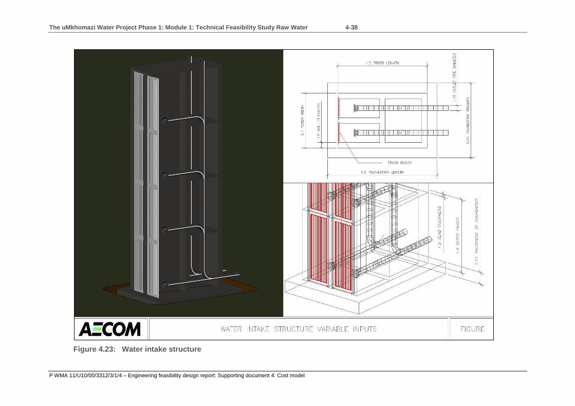
The uMkhomazi Water Project Phase 1: Module 1: Technical Feasibility Study Raw Water 4-38
P WMA 11/U10/00/3312/3/1/4 – Engineering feasibility design report: Supporting document 4: Cost model
Figure 4.23: Water intake structure

The uMkhomazi Water Project Phase 1: Module 1: Technical Feasibility Study Raw Water 4-39
P WMA 11/U10/00/3312/3/1/4 – Engineering feasibility design report: Supporting document 4: Cost model
Figure 4.24: Intake and outlet works variable input table

The uMkhomazi Water Project Phase 1: Module 1: Technical Feasibility Study Raw Water 4-40
P WMA 11/U10/00/3312/3/1/4 – Engineering feasibility design report: Supporting document 4: Cost model
Table 4.13 to Table 4.16 provides descriptions of the variable inputs, as shown in
Figure 4.24, for the intake structure, outlet works, stilling basin and the bridge deck
respectively.
Table 4.13: Intake structure variable input components
Intake structure
1.1 Tower width The width of the tower in the direction of flow. The front width of the
water intake tower.
1.2 Tower length The length of the tower normal to the direction of flow.
1.3 Tower height The height of the tower from natural ground level.
1.4 Story height The difference in height between levels.
1.5 Slab thickness The thickness of the floor slabs.
1.6
Ceiling height
(calculated or
read only)
The height calculated by subtracting the slab thickness from the story
height.
1.7 Number of stories The number of levels within the tower.
1.8 Wall thickness The thickness of the external walls of the water intake structure.
1.9 Foundation length The length of the foundation, which is parallel to the tower length.
1.10 Foundation
breadth The width of the foundation, which is parallel to the tower width.
1.11 Thickness of
foundation
The depth of the foundation from founding level to the natural ground
level.
1.12 Excavation batter
slopes The horizontal component of the slope is input.
1.13 Reinforcement in
tower
The amount of reinforcement in the tower that is calculated as a mass of
steel per unit of concrete.
1.14 Reinforcement in
foundation
The amount of reinforcement in the tower that is calculated as a mass of
steel per unit of concrete.
1.15 Outlet pipe
diameter
The diameter of the outlet pipe, which extends from the inlet to the outlet
works.
1.16
Number of outlet
pipes per intake
level
The number of intakes pipes per level. A maximum of two intakes may
be placed per intake level.
1.17 Number of intake
levels The number of levels from which water can be drawn.
1.18
Pipe length from
intake tower to
outlet works
The distance between the intake tower and the outlet works.

The uMkhomazi Water Project Phase 1: Module 1: Technical Feasibility Study Raw Water 4-41
P WMA 11/U10/00/3312/3/1/4 – Engineering feasibility design report: Supporting document 4: Cost model
Table 4.14: Outlet works variable input components
Outlet works
2.4 Foundation width The width of the outlet works foundation.
2.5 Foundation length The length of the outlet works foundation.
2.6 Foundation
thickness
The depth of the foundation between the founding level and the natural
ground level.
2.7 Reinforcing The amount of reinforcement that is calculated as a mass per unit of
concrete for both the foundation and the outlet works superstructure.
2.8 Excavation batter
slopes The horizontal component of the batter slope is input.
2.9 Floor thickness The thickness of the outlet work’s floors.
2.10 Wall thickness The thickness of the external walls of the outlet works.
2.11 Structure length The length of the outlet work’s superstructure.
2.12 Structure width The width of the outlet work’s superstructure.
2.13 Structure height The height of the superstructure from the natural ground level to the top
of the structure.
Table 4.15: Stilling basin variable input components
Stilling basin
2.14 Basin length The length of the basin from the outlet works to the point of discharge
into the river.
2.15 Wall heights The height of the walls on either side of the stilling basin.
2.16 Wall thickness The thickness of the walls on either side of the stilling basin.
2.17 Floor thickness The thickness of the stilling basin floor.

The uMkhomazi Water Project Phase 1: Module 1: Technical Feasibility Study Raw Water 4-42
P WMA 11/U10/00/3312/3/1/4 – Engineering feasibility design report: Supporting document 4: Cost model
Table 4.16: Bridge deck variable input components
Bridge deck
2.18 Deck width The width of the bridge deck that runs from the embankment to the
intake structure.
2.19 Deck thickness The thickness of the bridge deck.
2.20 Embankment
slope
The horizontal component of the embankment slope is an input. The
embankment slope is equal to the upstream slope of the embankment.
2.21 Bridge length (Calculated or read only) The length of the bridge is calculated from the
embankment slope and the height of the intake structure.
2.22 Reinforcement
The quantity of reinforcement to be used within the bridge deck. The
amount of reinforcement is determined as a mass per unit volume of
concrete.
2.23 Pier width The width of the piers used to support the bridge deck.
2.24 Pier length The length of the piers used to support the bridge deck.
2.25 Number of piers The number of piers required to support the bridge deck.
2.26 Foundation width The width of the foundations used to support the bridge piers.
2.27 Foundation length The length of the foundations used to support the bridge piers.
2.28 Foundation
thickness
The thickness of the foundation. The depth of the foundation between
the founding level and the natural ground level;
2.29 Foundation
reinforcement
The quantity of reinforcement to be used within the foundation. The
amount of reinforcement is determined as a mass per unit volume of
concrete.
2.30 Pier reinforcement
The quantity of reinforcement to be used within the bridge piers. The
amount of reinforcement is determined as a mass per unit volume of
concrete.
2.31 Site access roads-
gravel roads
The length of the gravel roads that need to be constructed in order to
provide access to the water intake tower and outlet works.
2.32 Gates and
screens
Select Yes/No by pushing the radio button. Indicate whether gates and
screens need to be included within the cost;
2.33 Lifting equipment Select Yes/No by pushing the radio button. Indicate whether lifting
equipment needs to be included within the cost.
2.34 Pipework and
valves
Select Yes/No by pushing the radio button. Indicate whether pipework
and valves need to be included within the cost.
2.35 Electrical
installation
Select Yes/No by pushing the radio button. Indicate whether electrical
installation needs to be included within the cost.
4.3.5 Transfer tunnel input parameters
The transfer tunnel variable inputs require the input of a long section for the tunnel.
The long section requires the chainage value and the corresponding natural ground
level above the tunnel. Input values need to be specified for the tunnel, ventilation
shafts, the adits and the inlet and outlet portals. Figure 4.25 shows the layout of the
transfer tunnel variable inputs table.

The uMkhomazi Water Project Phase 1: Module 1: Technical Feasibility Study Raw Water 4-43
P WMA 11/U10/00/3312/3/1/4 – Engineering feasibility design report: Supporting document 4: Cost model
Figure 4.25: Transfer tunnel variable input
a) Tunnel alignment
The tunnel alignment with its corresponding chainages needs to be input in order
to determine the support class and rock class along the length of the tunnel. The
type of rock class is determined by the distance between the natural ground level
and the invert of the tunnel. There are seven rock classes that can be used
within the tunnel, namely:
Rock class 1: Spot bolting;
Rock class 2: Light pattern bolting;
Rock class 3: Pattern bolting with mesh;
Rock class 4: Bolts and mesh with shotcrete over 120 degrees;
Rock class 5: Bolts and mesh with shotcrete over 180 degrees;
Rock class 6: Arch ribs with mesh and shotcrete over 330 degrees; and
Rock class 7: Pattern bolting for spalling rock.

The uMkhomazi Water Project Phase 1: Module 1: Technical Feasibility Study Raw Water 4-44
P WMA 11/U10/00/3312/3/1/4 – Engineering feasibility design report: Supporting document 4: Cost model
The input of the tunnel alignment also enables the distance between natural
ground level and the tunnel invert to be determined in order to calculate the
required quantities related to the ventilation shafts. By typing in the chainage that
specifies the position of the ventilation shaft, the distance between the natural
ground level and the tunnel invert is determined.
Figure 4.26 shows the profile of the transfer tunnel with the location of the
ventilation shafts. Table 4.17 and Table 4.18 provide descriptions of the variable
inputs, as shown in Figure 4.25, for the tunnel alignment.
Figure 4.26: Transfer tunnel profile
0
200
400
600
800
1000
1200
1400
1600
1800
0 5000 10000 15000 20000 25000 30000 35000
Ele
vati
on
(M
ASL
)
Chainage (m)
Transfer tunnel
NGL
Tunnel
Shaft 1
Shaft 2
Shaft 3

The uMkhomazi Water Project Phase 1: Module 1: Technical Feasibility Study Raw Water 4-45
P WMA 11/U10/00/3312/3/1/4 – Engineering feasibility design report: Supporting document 4: Cost model
Table 4.17: Tunnel alignment variable input components
Tunnel alignment
1.1 Number of tunnels The number of tunnels that need to be constructed.
1.2 Diameter (total diameter
including lining) The outer diameter of the tunnel.
1.3 Type of tunnel
Refers to the method that will be used to construct the
tunnel. The tunnel can either be constructed using a tunnel
boring machine (TBM) or by Drill and Blast (DBT).
Depending on the type of method used, different support
classes are relevant.
1.4 Rock type The type or rock the tunnel will be bored. Select between
rock type A, B, C, D, E, F, G, H (see Table 4.18).
1.5 Lining thickness The thickness of the tunnel lining.
1.6 Upstream invert level The invert level at the inlet portal of the tunnel.
1.7 Downstream invert level The invert level at the outlet portal of the tunnel.
1.8 Mesh mass per m
2 of
lining The mass of the mesh per square meter of mesh.
1.9 Class 4 Shotcrete
thicknesses The thickness of the shotcrete for class 4.
1.10 Class 5 Shotcrete
thickness The thickness of the shotcrete for class 5.
1.11 Class 6 Shotcrete
thickness The thickness of the shotcrete for class 6.
1.12 Spacing of arch ribs The distance between subsequent arch ribs.
1.13 Inlet portal excavation
volume
The amount of material that needs to be excavated to form
the inlet portal.
1.14 Outlet portal excavation
volume
The amount of material that needs to be excavated to form
the outlet portal.
1.15 Adit lengths The length of the adits from the inlet portal at natural ground
level to where they connect to the transfer tunnel.
1.16 Adit lining thickness The thickness of the linings used within the adits.
1.17 Adit diameter (outer
diameter) The outer diameter of the adits.
The occurrence of following rock types on the tunnel alignment should be
estimated (as shown in Table 4.18):
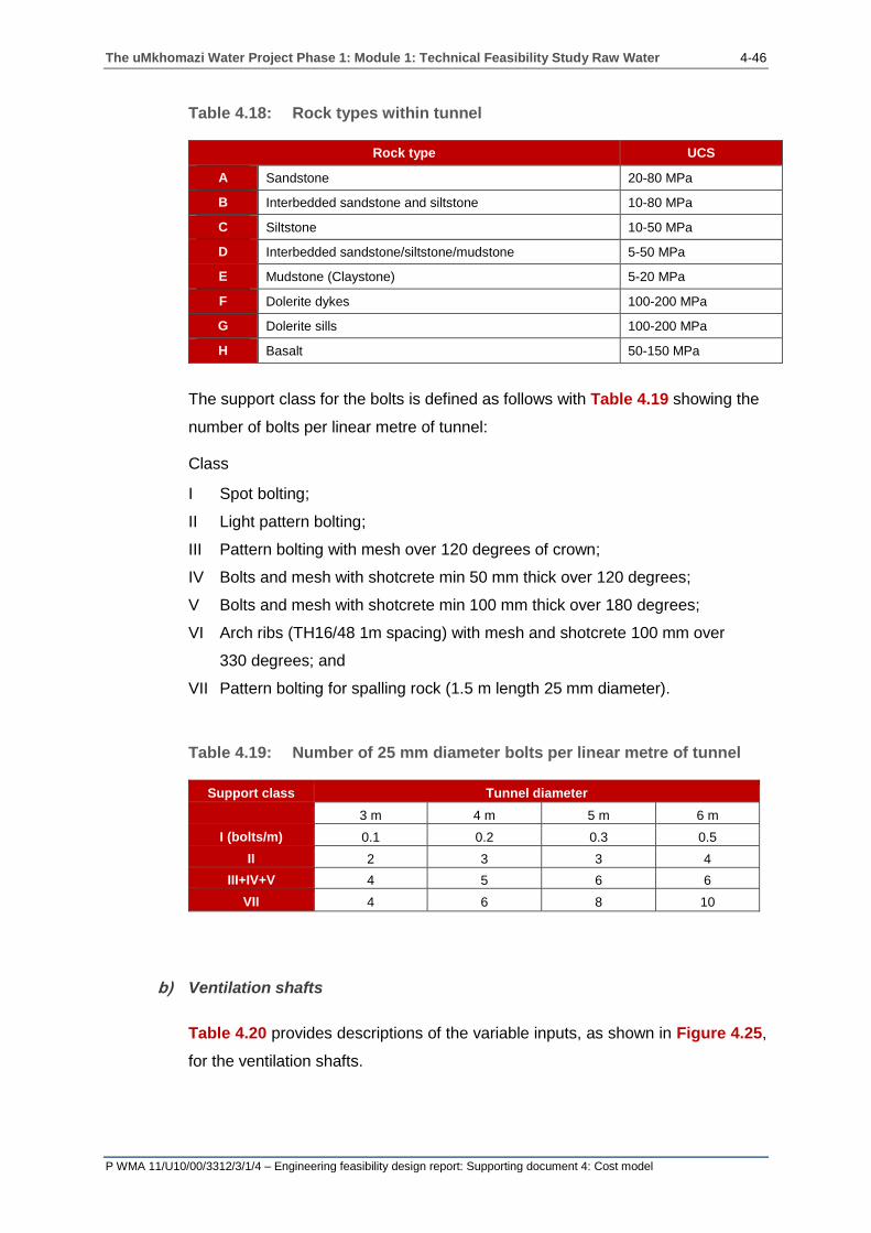
The uMkhomazi Water Project Phase 1: Module 1: Technical Feasibility Study Raw Water 4-46
P WMA 11/U10/00/3312/3/1/4 – Engineering feasibility design report: Supporting document 4: Cost model
Table 4.18: Rock types within tunnel
Rock type UCS
A Sandstone 20-80 MPa
B Interbedded sandstone and siltstone 10-80 MPa
C Siltstone 10-50 MPa
D Interbedded sandstone/siltstone/mudstone 5-50 MPa
E Mudstone (Claystone) 5-20 MPa
F Dolerite dykes 100-200 MPa
G Dolerite sills 100-200 MPa
H Basalt 50-150 MPa
The support class for the bolts is defined as follows with Table 4.19 showing the
number of bolts per linear metre of tunnel:
Class
I Spot bolting;
II Light pattern bolting;
III Pattern bolting with mesh over 120 degrees of crown;
IV Bolts and mesh with shotcrete min 50 mm thick over 120 degrees;
V Bolts and mesh with shotcrete min 100 mm thick over 180 degrees;
VI Arch ribs (TH16/48 1m spacing) with mesh and shotcrete 100 mm over
330 degrees; and
VII Pattern bolting for spalling rock (1.5 m length 25 mm diameter).
Table 4.19: Number of 25 mm diameter bolts per linear metre of tunnel
Support class Tunnel diameter
3 m 4 m 5 m 6 m
I (bolts/m) 0.1 0.2 0.3 0.5
II 2 3 3 4
III+IV+V 4 5 6 6
VII 4 6 8 10
b) Ventilation shafts
Table 4.20 provides descriptions of the variable inputs, as shown in Figure 4.25,
for the ventilation shafts.

The uMkhomazi Water Project Phase 1: Module 1: Technical Feasibility Study Raw Water 4-47
P WMA 11/U10/00/3312/3/1/4 – Engineering feasibility design report: Supporting document 4: Cost model
Table 4.20: Ventilation shaft input components
Ventilation shaft
2.1 Internal diameter of
shaft The internal diameter of the shaft excluding any linings
2.2 Concrete lining
thickness
The thickness of the concrete lining used within the ventilation
shaft
2.3 Steel encasing
thickness
The thickness of the steel encasing used within the ventilation
shaft
2.4 Shaft 1 (Chainage)
The position of the ventilation shaft 1 along the length of the
tunnel. The chainage that is input here needs to correspond to
a chainage that was input in the tunnel alignment input table
2.5 Shaft 2 (Chainage)
The position of the ventilation shaft 2 along the length of the
tunnel. The chainage that is input here needs to correspond to
a chainage that was input in the tunnel alignment input table
2.6 Shaft 3 (Chainage)
The position of the ventilation shaft 3 along the length of the
tunnel. The chainage that is input here needs to correspond to
a chainage that was input in the tunnel alignment input table
2.7 Density of
reinforcement The density of the reinforcement used within the tunnel
2.8 Access road – Gravel The length of the gravel access roads to the inlet portal,
ventilation shafts and outlet portals
2.9 Electricity to site Whether the cost of providing electricity to site needs to be
included
2.10
Water to site –
contractor (not
potable)
Whether the cost of providing water to site needs to be
included
2.11 Railhead and materials handling
4.3.6 Pipeline input parameters
Figure 4.27 shows the layout of the transfer tunnel variable inputs table and
Table 4.21 provides descriptions of the variable inputs.
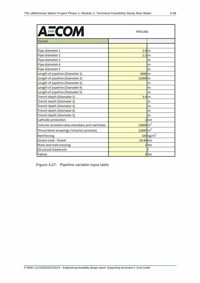
The uMkhomazi Water Project Phase 1: Module 1: Technical Feasibility Study Raw Water 4-48
P WMA 11/U10/00/3312/3/1/4 – Engineering feasibility design report: Supporting document 4: Cost model
Figure 4.27: Pipeline variable input table
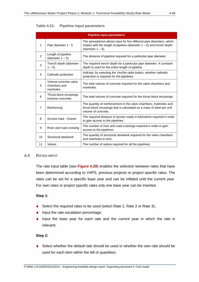
The uMkhomazi Water Project Phase 1: Module 1: Technical Feasibility Study Raw Water 4-49
P WMA 11/U10/00/3312/3/1/4 – Engineering feasibility design report: Supporting document 4: Cost model
Table 4.21: Pipeline input parameters
Pipeline input parameters
1 Pipe diameter 1 - 5
The spreadsheet allows input for five different pipe diameters, which
relates with the length of pipeline (diameter 1 – 5) and trench depth
(diameter 1 – 5).
2 Length of pipeline
(diameter 1 – 5) The distance of pipeline required for a particular pipe diameter.
3 Trench depth (diameter
1 – 5)
The required trench depth for a particular pipe diameter. A constant
depth is used for the entire length of pipeline.
4 Cathodic protection Indicate, by selecting the Yes/No radio button, whether cathodic
protection is required for the pipelines.
5
Volume concrete valve
chambers and
manholes
The total volume of concrete required for the valve chambers and
manholes.
6 Thrust block encasings
(volume concrete) The total volume of concrete required for the thrust block encasings.
7 Reinforcing
The quantity of reinforcement in the valve chambers, manholes and
thrust block encasings that is calculated as a mass of steel per unit
volume of concrete.
8 Access road – Gravel The required distance of access roads in kilometres required in order
to gain access to the pipelines.
9 River and road crossing The number of river and road crossings required in order to gain
access to the pipelines.
10 Structural steelwork The quantity of structural steelwork required for the valve chambers
and manholes in tons.
11 Valves The number of valves required for all the pipelines.
4.4 RATES INPUT
The rate input table (see Figure 4.28) enables the selection between rates that have
been determined according to VAPS, previous projects or project specific rates. The
rates can be set for a specific base year and can be inflated until the current year.
For own rates or project specific rates only one base year can be inserted.
Step 1:
Select the required rates to be used (select Rate 1, Rate 2 or Rate 3);
Input the rate escalation percentage;
Input the base year for each rate and the current year in which the rate is
relevant;
Step 2:
Select whether the default rate should be used or whether the own rate should be
used for each item within the bill of quantities;
The uMkhomazi Water Project Phase 1: Module 1: Technical Feasibility Study Raw Water 4-50
P WMA 11/U10/00/3312/3/1/4 – Engineering feasibility design report: Supporting document 4: Cost model
Insert the rates for each of the options;
Step 3:
Select whether the default rate escalation rate should be used or whether an
individual escalation rate should be used for the item;
Note: All cells that are highlighted in yellow require an action or an input.

The uMkhomazi Water Project Phase 1: Module 1: Technical Feasibility Study Raw Water 4-51
P WMA 11/U10/00/3312/3/1/4 – Engineering feasibility design report: Supporting document 4: Cost model
Figure 4.28: Rates input table

The uMkhomazi Water Project Phase 1: Module 1: Technical Feasibility Study Raw Water 4-52
P WMA 11/U10/00/3312/3/1/4 – Engineering feasibility design report: Supporting document 4: Cost model
4.5 CALCULATIONS
The spreadsheets provides some explanation and graphics on how the final volumes
are calculated. For an indepth explanation on each of the dam types and how the
quantities are determined refer to the technical section of this report. No input is
required on any of the calculation sheets as the input is conveyed from the variable
input tables.
Each dam calculation speadsheet contains all the dam type options, this enables the
selection of numerous dam designs for the river section, left flank and right flank.
Only the RCC river section may be used in combination with the other dam options.
Other combinations may be used but may lead to a lack of coherence in the transition
from one damtype to the other. Always ensure that the spillway chainage for the left
flank and right flank lie within the minimum and maximum chainage of the dam, even
if the river section, right flank and left flank are of the same dam type option.
By selecting the dam type for the river section, left and right flank, the spreadsheet
conveys to each dam type option which chainages the quantities for that dam type
need to be determined.
Figure 4.29 shows an example of calculation spreadsheets.
.
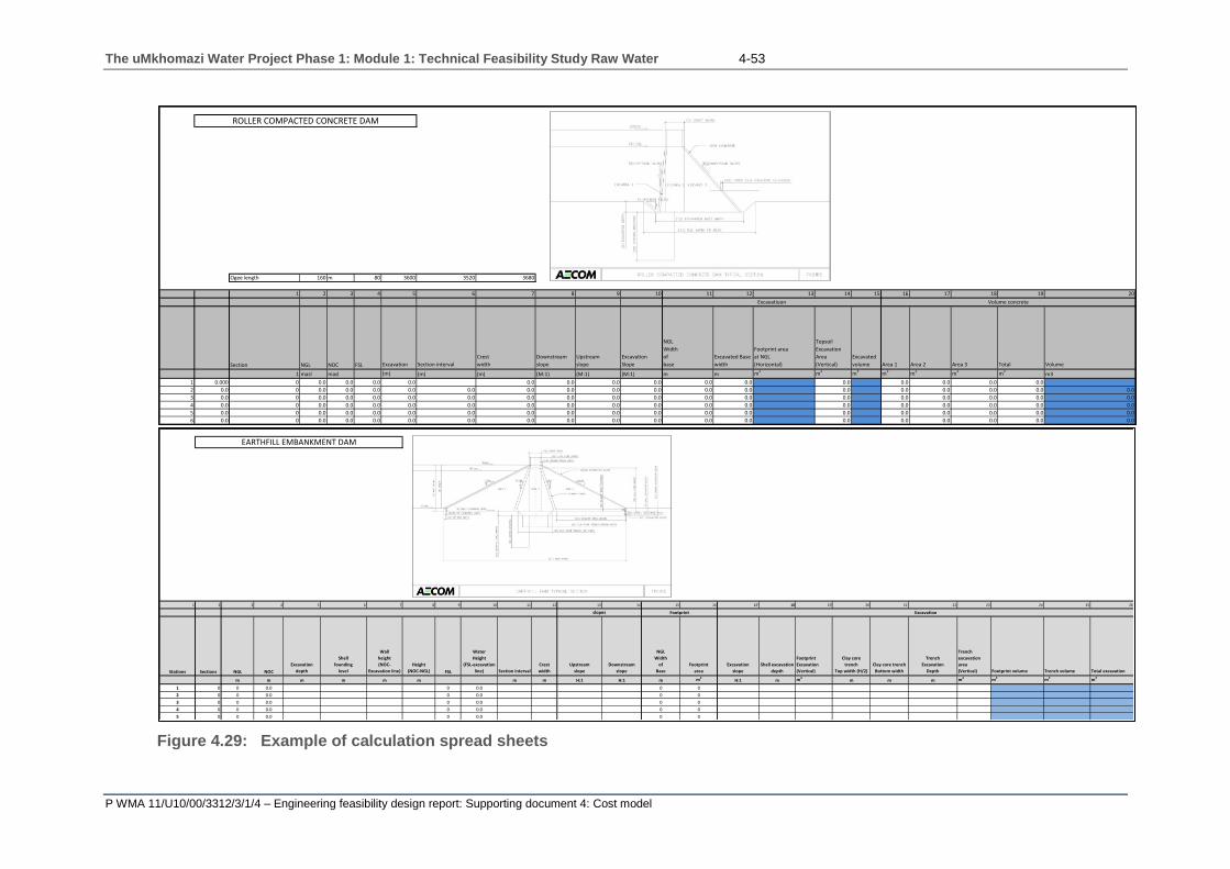
The uMkhomazi Water Project Phase 1: Module 1: Technical Feasibility Study Raw Water 4-53
P WMA 11/U10/00/3312/3/1/4 – Engineering feasibility design report: Supporting document 4: Cost model
Figure 4.29: Example of calculation spread sheets
Ogee length 160 m 80 3600 3520 3680
1 2 3 4 5 6 7 8 9 10 11 12 13 14 15 16 17 18 19 20
Section NGL NOC FSL Excavation Section interval
Crest
width
Downstream
slope
Upstream
slope
Excavation
Slope
NGL
Width
of
base
Excavated Base
width
Footprint area
at NGL
(Horizontal)
Topsoil
Excavation
Area
(Vertical)
Excavated
volume Area 1 Area 2 Area 3 Total Volume
1 masl masl (m) (m) (m) (M:1) (M:1) (M:1) m m m2 m2 m3 m2 m2 m2 m2m3
1 0.000 0 0.0 0.0 0.0 0.0 0.0 0.0 0.0 0.0 0.0 0.0 0.0 0.0 0.0 0.0 0.0
2 0.0 0 0.0 0.0 0.0 0.0 0.0 0.0 0.0 0.0 0.0 0.0 0.0 0.0 0.0 0.0 0.0 0.0 0.0
3 0.0 0 0.0 0.0 0.0 0.0 0.0 0.0 0.0 0.0 0.0 0.0 0.0 0.0 0.0 0.0 0.0 0.0 0.0
4 0.0 0 0.0 0.0 0.0 0.0 0.0 0.0 0.0 0.0 0.0 0.0 0.0 0.0 0.0 0.0 0.0 0.0 0.0
5 0.0 0 0.0 0.0 0.0 0.0 0.0 0.0 0.0 0.0 0.0 0.0 0.0 0.0 0.0 0.0 0.0 0.0 0.0
6 0.0 0 0.0 0.0 0.0 0.0 0.0 0.0 0.0 0.0 0.0 0.0 0.0 0.0 0.0 0.0 0.0 0.0 0.0
Excavatiuon Volume concrete
ROLLER COMPACTED CONCRETE DAM
1 2 3 4 5 6 7 8 9 10 11 12 13 14 15 16 17 18 19 20 21 22 23 24 25 26
Stations Sections NGL NOC
Excavation
depth
Shell
founding
level
Wall
height
(NOC-
Excavation line)
Height
(NOC-NGL) FSL
Water
Height
(FSL-excavation
line) Section interval
Crest
width
Upstream
slope
Downstream
slope
NGL
Width
of
Base
Footprint
area
Excavation
slope
Shell excavation
depth
Footprint
Excavation
(Vertical)
Clay core
trench
Top width (H/2)
Clay core trench
Bottom width
Trench
Excavation
Depth
Trench
excavation
area
(Vertical) Footprint volume Trench volume Total excavation
m m m m m m m m H:1 H:1 m m2H:1 m m2
m m m m2 m3 m3 m3
1 0 0 0.0 0 0.0 0 0
2 0 0 0.0 0 0.0 0 0
3 0 0 0.0 0 0.0 0 0
4 0 0 0.0 0 0.0 0 0
5 0 0 0.0 0 0.0 0 0
Excavation
EARTHFILL EMBANKMENT DAM
Embankment
slopes Footprint

The uMkhomazi Water Project Phase 1: Module 1: Technical Feasibility Study Raw Water 4-54
P WMA 11/U10/00/3312/3/1/4 – Engineering feasibility design report: Supporting document 4: Cost model
4.6 BILL OF QUANTITIES (BOQ)
The bill of quantities provides a breakdown of all the costs and volumes for each of
the embankment dam types. No input is required as the rates and quantities are
conveyed from the calculation spread sheets and rates input spread sheets.
The same bill of quantities is used for each of the dam types. Depending on what
dam type is selected for the river section, left flank and right flank, the corresponding
quantities will be input into the bill of quantities.
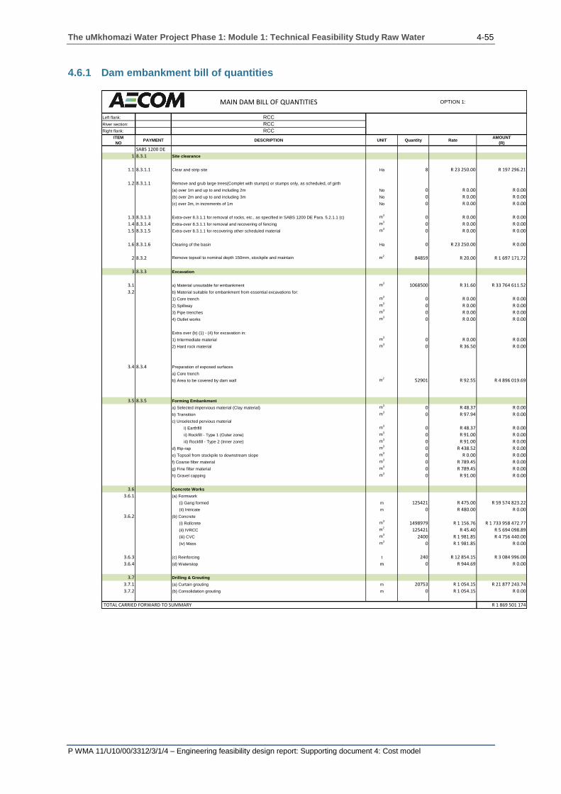
The uMkhomazi Water Project Phase 1: Module 1: Technical Feasibility Study Raw Water 4-55
P WMA 11/U10/00/3312/3/1/4 – Engineering feasibility design report: Supporting document 4: Cost model
4.6.1 Dam embankment bill of quantities
MAIN DAM BILL OF QUANTITIES OPTION 1:
Left flank: RCC
River section: RCC
Right flank: RCC
ITEM
NOPAYMENT DESCRIPTION UNIT Quantity Rate
AMOUNT
(R)
SABS 1200 DE
1 8.3.1 Site clearance
1.1 8.3.1.1 Clear and strip site Ha 8 R 23 250.00 R 197 296.21
1.2 8.3.1.1 Remove and grub large trees(Complet with stumps) or stumps only, as scheduled, of girth
(a) over 1m and up to and including 2m No 0 R 0.00 R 0.00
(b) over 2m and up to and including 3m No 0 R 0.00 R 0.00
(c) over 3m, in increments of 1m No 0 R 0.00 R 0.00
1.3 8.3.1.3 Extra-over 8.3.1.1 for removal of rocks, etc., as specified in SABS 1200 DE Para. 5.2.1.1 (c) m3
0 R 0.00 R 0.00
1.4 8.3.1.4 Extra-over 8.3.1.1 for removal and recovering of fencing m3
0 R 0.00 R 0.00
1.5 8.3.1.5 Extra-over 8.3.1.1 for recovering other scheduled material m3
0 R 0.00 R 0.00
1.6 8.3.1.6 Clearing of the basin Ha 0 R 23 250.00 R 0.00
2 8.3.2 Remove topsoil to nominal depth 150mm, stockpile and maintain m2
84859 R 20.00 R 1 697 171.72
3 8.3.3 Excavation
3.1 a) Material unsuitable for embankment m3
1068500 R 31.60 R 33 764 611.52
3.2 b) Material suitable for embankment from essential excavations for:
1) Core trench m3
0 R 0.00 R 0.00
2) Spillway m3
0 R 0.00 R 0.00
3) Pipe trenches m3
0 R 0.00 R 0.00
4) Outlet works m3
0 R 0.00 R 0.00
Extra over (b) (1) - (4) for excavation in:
1) Intermediate material m3
0 R 0.00 R 0.00
2) Hard rock material m3
0 R 36.50 R 0.00
3.4 8.3.4 Preparation of exposed surfaces
a) Core trench
b) Area to be covered by dam wall m2
52901 R 92.55 R 4 896 019.69
3.5 8.3.5 Forming Embankment
a) Selected impervious material (Clay material) m3
0 R 48.37 R 0.00
b) Transition m3
0 R 97.94 R 0.00
c) Unselected pervious material
i) Earthfill m3
0 R 48.37 R 0.00
ii) Rockfill - Type 1 (Outer zone) m3
0 R 91.00 R 0.00
iii) Rockfill - Type 2 (Inner zone) m3
0 R 91.00 R 0.00
d) Rip-rap m3
0 R 438.52 R 0.00
e) Topsoil from stockpile to downstream slope m3
0 R 0.00 R 0.00
f) Coarse filter material m3
0 R 789.45 R 0.00
g) Fine filter material m3
0 R 789.45 R 0.00
h) Gravel capping m3
0 R 91.00 R 0.00
3.6 Concrete Works
3.6.1 (a) Formwork
(i) Gang formed m 125421 R 475.00 R 59 574 823.22
(ii) Intricate m 0 R 480.00 R 0.00
3.6.2 (b) Concrete
(i) Rollcrete m3
1498979 R 1 156.76 R 1 733 958 472.77
(ii) IVRCC m2
125421 R 45.40 R 5 694 098.89
(iii) CVC m3
2400 R 1 981.85 R 4 756 440.00
(iv) Mass m3
0 R 1 981.85 R 0.00
3.6.3 (c) Reinforcing t 240 R 12 854.15 R 3 084 996.00
3.6.4 (d) Waterstop m 0 R 944.69 R 0.00
3.7 Drilling & Grouting
3.7.1 (a) Curtain grouting m 20753 R 1 054.15 R 21 877 243.74
3.7.2 (b) Consolidation grouting m 0 R 1 054.15 R 0.00
R 1 869 501 174TOTAL CARRIED FORWARD TO SUMMARY

The uMkhomazi Water Project Phase 1: Module 1: Technical Feasibility Study Raw Water 4-56
P WMA 11/U10/00/3312/3/1/4 – Engineering feasibility design report: Supporting document 4: Cost model
4.6.2 Diversion works bill of quantities
DIVERSION WORKS
ITEM
NOPAYMENT UNIT Quantity Rate (R)
AMOUNT
(R)
STAGE 1: PORTALS AND TUNNELS
1 1.0 SITE CLEARANCE
1.1 Clear and grub
(a) Portal footprints ha 0.12 R 23 250.00 R 2 794.38
1.2 Remove and grub large trees and tree stumps of girth
(a) Over 1 m and up to and including 2m No 0.00 R 0.00 R 0.00
1.3 Remove topsoil to nominal depth of 150 mm and stockpile m³ 1 201.89 R 10.28 R 12 355.39
2 2.0 EXCAVATION AND BACKFILL FOR DAMS AND WATERWAYS
Bulk Excavation
2.1 Inlet portal
(a) Excavate in all materials
(i) Excavation (stockpile) m³ 3 025.00 R 91.00 R 275 275.00
(b) Extra over for:
(i) Intermediate m³ 302.50 R 0.00
(ii) Hard Rock m³ 302.50 R 31.60 R 9 559.00
(iii) Boulder, Class A m³ 0.00 R 0.00 R 0.00
(iv) Boulder, Class B m³ 0.00 R 0.00 R 0.00
2.2 Outlet Portal
(a) Excavate in all materials
(i) Excavation (stockpile) m³ 3 025.00 R 91.00 R 275 275.00
(b) Extra over for:
(i) Intermediate m³ 302.50 R 0.00
(ii) Hard Rock m³ 302.50 R 31.60 R 9 559.00
(iii) Boulder, Class A m³ 0.00 R 0.00 R 0.00
(iv) Boulder, Class B m³ 0.00 R 0.00 R 0.00
2.3 Dewatering Sum 0.00 R 0.00 R 0.00
SUB TOTAL: STAGE 1 R 584 817.77
STAGE 2 Cofferdam
3 SITE CLEARANCE
3.1 Clear and grub
(a) Embankment footprint ha 0.52 R 26 546.00 R 13 910
3.2 Remove and grub large trees and tree stumps of girth
(a) over 1 m and up to and including 2 m No 0.00 R 0.00 R 0
3.3 Remove topsoil to nominal depth of 150 mm and stockpile m³ 5 240.00 R 10.28 R 53 867
4 4.1 EXCAVATIONS AND BACKFILL FOR DAMS AND WATERWAYS
(a) Excavate all materials
(i) Topsoil at Upstream & Downstream cofferdam m³ 5 240.00 R 51.42 R 269 441
5 5.1 EMBANKMENT CONSTRUCTION
Earthfill Upstream & Downstream Cofferdam Construction.
(a) Forming Embankment
Using material from designated borrow areas or commercial sources
(i) Soil cement at 3% cement m³ 2 860.00 R 300.00 R 858 000
(ii) Rockfill m³ 22 140.00 R 91.00 R 2 014 740
SUB TOTAL: COFFERDAM R 3 209 958
6 TUNNEL CONSTRUCTION
6.1 TUNNEL EXCAVATION
(a) Tunnel m³ 14 872.30 R 2 700.00 R 40 155 209
6.2 ROCK SUPPORT
(a) Rockbolts m 4 208.00 R 50.00 R 210 400
(b) Shotcrete m³ 3 304.96 R 3 350.00 R 11 071 601
(c) Reinforcing mesh m² 3 304.96 R 35.00 R 115 673
6.3 DEWATERING Sum 1.00 R 100 000.00 R 100 000
SUB TOTAL: TUNNEL R 51 652 883
SUB TOTAL: STAGE 1 + STAGE 2 R 55 447 659
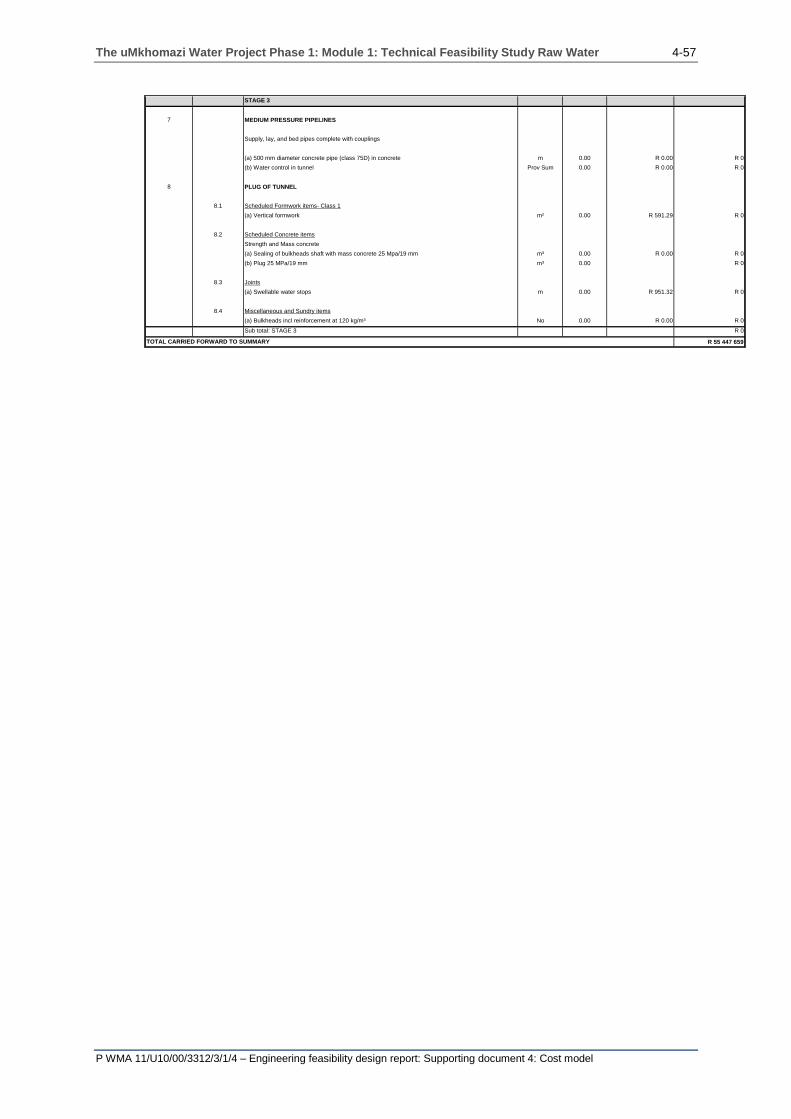
The uMkhomazi Water Project Phase 1: Module 1: Technical Feasibility Study Raw Water 4-57
P WMA 11/U10/00/3312/3/1/4 – Engineering feasibility design report: Supporting document 4: Cost model
STAGE 3
7 MEDIUM PRESSURE PIPELINES
Supply, lay, and bed pipes complete with couplings
(a) 500 mm diameter concrete pipe (class 75D) in concrete m 0.00 R 0.00 R 0
(b) Water control in tunnel Prov Sum 0.00 R 0.00 R 0
8 PLUG OF TUNNEL
8.1 Scheduled Formwork items- Class 1
(a) Vertical formwork m² 0.00 R 591.29 R 0
8.2 Scheduled Concrete items
Strength and Mass concrete
(a) Sealing of bulkheads shaft with mass concrete 25 Mpa/19 mm m³ 0.00 R 0.00 R 0
(b) Plug 25 MPa/19 mm m³ 0.00 R 0
8.3 Joints
(a) Swellable water stops m 0.00 R 951.32 R 0
8.4 Miscellaneous and Sundry items
(a) Bulkheads incl reinforcement at 120 kg/m³ No 0.00 R 0.00 R 0
Sub total: STAGE 3 R 0
R 55 447 659TOTAL CARRIED FORWARD TO SUMMARY
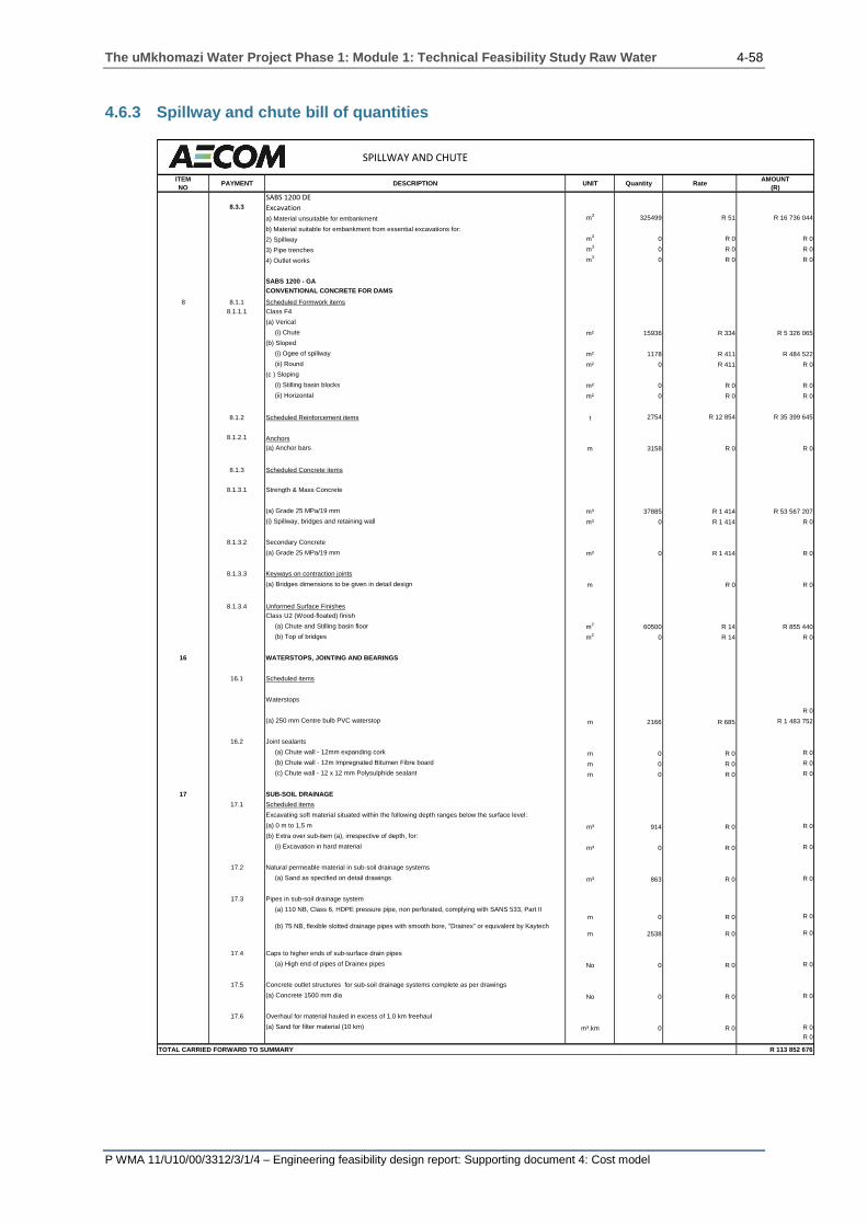
The uMkhomazi Water Project Phase 1: Module 1: Technical Feasibility Study Raw Water 4-58
P WMA 11/U10/00/3312/3/1/4 – Engineering feasibility design report: Supporting document 4: Cost model
4.6.3 Spillway and chute bill of quantities
SPILLWAY AND CHUTE
ITEM
NOPAYMENT DESCRIPTION UNIT Quantity Rate
AMOUNT
(R)
SABS 1200 DE8.3.3 Excavation
a) Material unsuitable for embankment m3
325499 R 51 R 16 736 044
b) Material suitable for embankment from essential excavations for:
2) Spillway m3
0 R 0 R 0
3) Pipe trenches m3
0 R 0 R 0
4) Outlet works m3
0 R 0 R 0
SABS 1200 - GA
CONVENTIONAL CONCRETE FOR DAMS
8 8.1.1 Scheduled Formwork items
8.1.1.1 Class F4
(a) Verical
(i) Chute m² 15936 R 334 R 5 326 065
(b) Sloped
(i) Ogee of spillway m² 1178 R 411 R 484 522
(ii) Round m² 0 R 411 R 0
(c ) Sloping
(i) Stilling basin blocks m² 0 R 0 R 0
(ii) Horizontal m² 0 R 0 R 0
8.1.2 Scheduled Reinforcement items t 2754 R 12 854 R 35 399 645
8.1.2.1 Anchors
(a) Anchor bars m 3158 R 0 R 0
8.1.3 Scheduled Concrete items
8.1.3.1 Strength & Mass Concrete
(a) Grade 25 MPa/19 mm m³ 37885 R 1 414 R 53 567 207
(i) Spillway, bridges and retaining wall m³ 0 R 1 414 R 0
8.1.3.2 Secondary Concrete
(a) Grade 25 MPa/19 mm m³ 0 R 1 414 R 0
8.1.3.3 Keyways on contraction joints
(a) Bridges dimensions to be given in detail design m R 0 R 0
8.1.3.4 Unformed Surface Finishes
Class U2 (Wood-floated) finish
(a) Chute and Stilling basin floor m2
60500 R 14 R 855 440
(b) Top of bridges m2
0 R 14 R 0
16 WATERSTOPS, JOINTING AND BEARINGS
16.1 Scheduled items
Waterstops
R 0
(a) 250 mm Centre bulb PVC waterstop m 2166 R 685 R 1 483 752
16.2 Joint sealants
(a) Chute wall - 12mm expanding cork m 0 R 0 R 0
(b) Chute wall - 12m Impregnated Bitumen Fibre board m 0 R 0 R 0
(c) Chute wall - 12 x 12 mm Polysulphide sealant m 0 R 0 R 0
17 SUB-SOIL DRAINAGE
17.1 Scheduled items
Excavating soft material situated within the following depth ranges below the surface level:
(a) 0 m to 1,5 m m³ 914 R 0 R 0
(b) Extra over sub-item (a), irrespective of depth, for:
(i) Excavation in hard material m³ 0 R 0 R 0
17.2 Natural permeable material in sub-soil drainage systems
(a) Sand as specified on detail drawings m³ 863 R 0 R 0
17.3 Pipes in sub-soil drainage system
(a) 110 NB, Class 6, HDPE pressure pipe, non perforated, complying with SANS 533, Part II
m 0 R 0 R 0
(b) 75 NB, flexible slotted drainage pipes with smooth bore, "Drainex" or equivalent by Kaytech
m 2538 R 0 R 0
17.4 Caps to higher ends of sub-surface drain pipes
(a) High end of pipes of Drainex pipes No 0 R 0 R 0
17.5 Concrete outlet structures for sub-soil drainage systems complete as per drawings
(a) Concrete 1500 mm dia No 0 R 0 R 0
17.6 Overhaul for material hauled in excess of 1.0 km freehaul
(a) Sand for filter material (10 km) m³.km 0 R 0 R 0
R 0
TOTAL CARRIED FORWARD TO SUMMARY R 113 852 676
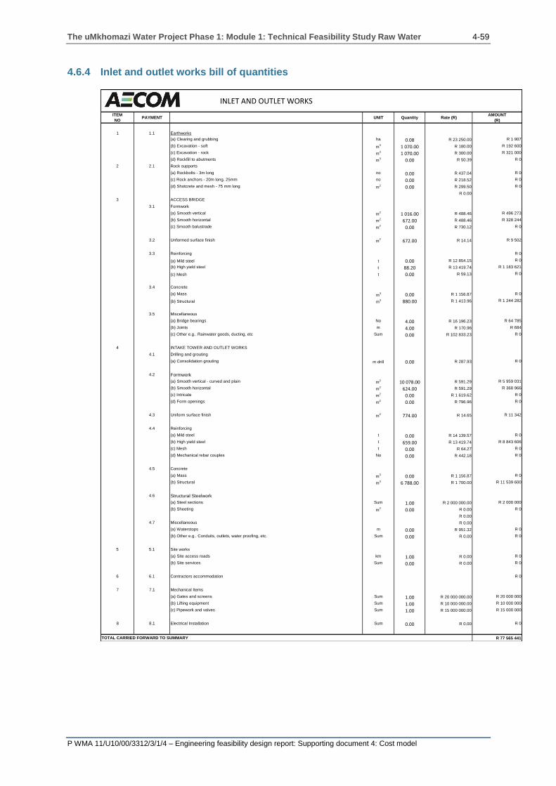
The uMkhomazi Water Project Phase 1: Module 1: Technical Feasibility Study Raw Water 4-59
P WMA 11/U10/00/3312/3/1/4 – Engineering feasibility design report: Supporting document 4: Cost model
4.6.4 Inlet and outlet works bill of quantities
INLET AND OUTLET WORKS
ITEM
NOPAYMENT UNIT Quantity Rate (R)
AMOUNT
(R)
1 1.1 Earthworks
(a) Clearing and grubbing ha 0.08 R 23 250.00 R 1 907
(b) Excavation - soft m3 1 070.00 R 180.00 R 192 600
(c) Excavation - rock m3 1 070.00 R 300.00 R 321 000
(d) Rockfill to abutments m3 0.00 R 50.39 R 0
2 2.1 Rock supports
(a) Rockbolts - 3m long no 0.00 R 437.04 R 0
(c) Rock anchors - 20m long, 25mm no 0.00 R 218.52 R 0
(d) Shotcrete and mesh - 75 mm long m2 0.00 R 299.50 R 0
R 0.00
3 ACCESS BRIDGE
3.1 Formwork
(a) Smooth vertical m2 1 016.00 R 488.46 R 496 273
(b) Smooth horizontal m2 672.00 R 488.46 R 328 244
(c) Smooth balustrade m2 0.00 R 730.12 R 0
3.2 Unformed surface finish m2 672.00 R 14.14 R 9 502
3.3 Reinforcing R 0
(a) Mild steel t 0.00 R 12 854.15 R 0
(b) High yield steel t 88.20 R 13 419.74 R 1 183 621
(c) Mesh t 0.00 R 59.13 R 0
3.4 Concrete
(a) Mass m3 0.00 R 1 156.87 R 0
(b) Structural m3 880.00 R 1 413.96 R 1 244 282
3.5 Miscellaneous
(a) Bridge bearings No 4.00 R 16 196.23 R 64 785
(b) Joints m 4.00 R 170.96 R 684
(c) Other e.g.. Rainwater goods, ducting, etc Sum 0.00 R 102 833.23 R 0
4 INTAKE TOWER AND OUTLET WORKS
4.1 Drilling and grouting
(a) Consolidation grouting m drill 0.00 R 287.93 R 0
4.2 Formwork
(a) Smooth vertical - curved and plain m2 10 078.00 R 591.29 R 5 959 031
(b) Smooth horizontal m2 624.00 R 591.29 R 368 966
(c) Intricate m2 0.00 R 1 619.62 R 0
(d) Form openings m2 0.00 R 796.96 R 0
4.3 Uniform surface finish m2 774.00 R 14.65 R 11 342
4.4 Reinforcing
(a) Mild steel t 0.00 R 14 139.57 R 0
(b) High yield steel t 659.00 R 13 419.74 R 8 843 606
(c) Mesh t 0.00 R 64.27 R 0
(d) Mechanical rebar couples No 0.00 R 442.18 R 0
4.5 Concrete
(a) Mass m3 0.00 R 1 156.87 R 0
(b) Structural m3 6 788.00 R 1 700.00 R 11 539 600
4.6 Structural Steelwork
(a) Steel sections Sum 1.00 R 2 000 000.00 R 2 000 000
(b) Sheeting m2 0.00 R 0.00 R 0
R 0.00
4.7 Miscellaneous R 0.00
(a) Waterstops m 0.00 R 951.32 R 0
(b) Other e.g.. Conduits, outlets, water proofing, etc. Sum 0.00 R 0.00 R 0
5 5.1 Site works
(a) Site access roads km 1.00 R 0.00 R 0
(b) Site services Sum 0.00 R 0.00 R 0
6 6.1 Contractors accommodation R 0
7 7.1 Mechanical Items
(a) Gates and screens Sum 1.00 R 20 000 000.00 R 20 000 000
(b) Lifting equipment Sum 1.00 R 10 000 000.00 R 10 000 000
(c) Pipework and valves Sum 1.00 R 15 000 000.00 R 15 000 000
8 8.1 Electrical Installation Sum 0.00 R 0.00 R 0
R 77 565 441TOTAL CARRIED FORWARD TO SUMMARY

The uMkhomazi Water Project Phase 1: Module 1: Technical Feasibility Study Raw Water 4-60
P WMA 11/U10/00/3312/3/1/4 – Engineering feasibility design report: Supporting document 4: Cost model
4.6.5 Transfer tunnel bill of quantities
ITEM
NO PAY DESCRIPTION UNIT Quantity Rate Total
1 1.0 Adits
1.1 Adit portal excavation m3
80 000 R 92.55 R 7 403 992
1.2 Adit excavation m3
61 200 R 1 516.79 R 92 827 552
1.3 Adit tunnel lining m3
16 830 R 2 545.12 R 42 834 409
2 2.0 Tunnel Excavation
2.1 (a) Rock Class I m3
0.0 R 1 182.58 R 0
2.2 (b) Rock Class II m3
152 054.0 R 1 182.58 R 179 816 337
2.3 (c) Rock Class III m3
191 638.0 R 1 285.42 R 246 334 420
2.4 (d) Rock Class IV m3
0.0 R 1 439.67 R 0
2.5 (e) Rock Class V m3
0.0 R 1 542.50 R 0
2.6 (f) Rock Class VI m3
84 824.0 R 2 313.75 R 196 261 323
2.7 (g) Rock Class VII m3
0.0 R 822.67 R 0
3 3.0 Portal excavations
3.1 Inlet portal m3
450 000 R 92.55 R 41 647 456
3.2 Outlet portal m3
640 000 R 92.55 R 59 231 938
3.2 Adit portal m3
80 000 R 92.55 R 7 403 992
4 4.0 Rock Support
4.1 (a) Rockbolts m 306 100 R 257.08 R 78 693 126
4.2 (b) Shotcrete m3
7 582 R 5 398.74 R 40 933 279
4.3 (c) Reinforcing mesh m2
220 949 R 77.12 R 17 040 674
4.4 (d) Steel arches and lagging No 6 750 R 0.00 R 0
5 5.0 Concrete
5.1 (a) Linings m3
100 434 R 2 545.12 R 255 616 815
5.2 (b) Overbreak concrete: TBM m2
2 009 R 514.17 R 1 032 795
5.3 (c) Overbreak concrete: DBT m2
0 R 2 056.66 R 0
5.4 (d) Concrete in structures m3
R 1 285.42 R 0
6 6.0 Formwork
6.1 (a) Smooth curved in tunnel m2
R 668.42 R 0
6.2 (b) Structures - intricate m2
R 524.45 R 0
7 7.0 Reinforcement ton 4 521 R 12 854.15 R 58 113 626
8 8.0 Pre-cast concrete inverts m R 1 285.42 R 0
9 9.0 Grouting m2
428 516 R 442.18 R 189 482 434
10 10.0 Waterproof lining m2
428 516 R 771.25 R 330 492 617
R 1 845 166 786
TRANSFER TUNNEL
TOTAL CARRIED FORWARD TO SUMMARY
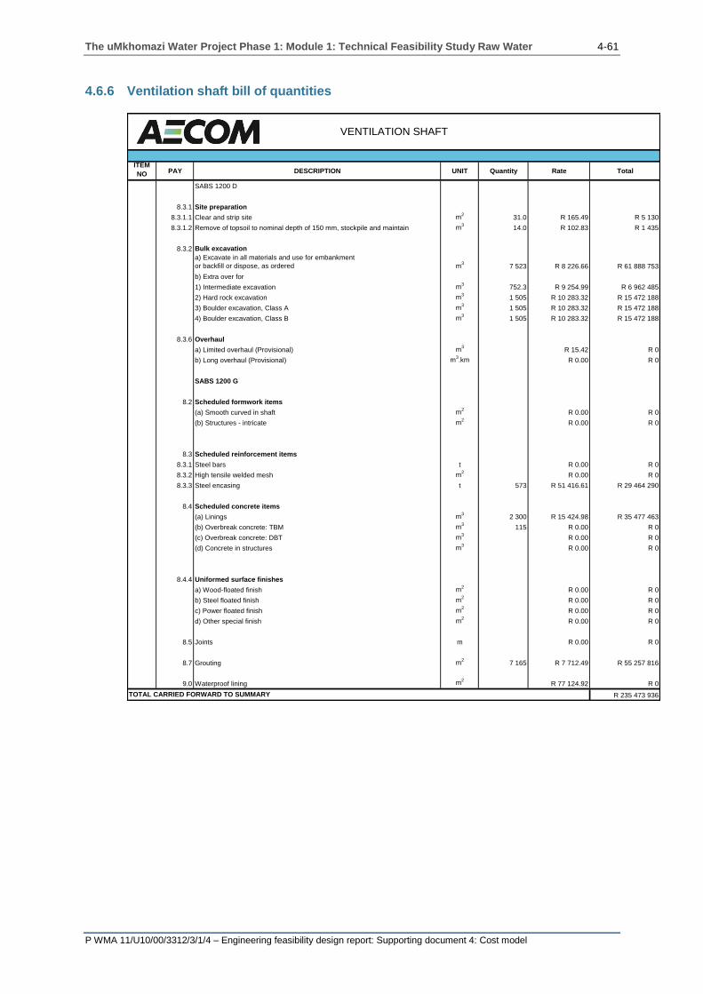
The uMkhomazi Water Project Phase 1: Module 1: Technical Feasibility Study Raw Water 4-61
P WMA 11/U10/00/3312/3/1/4 – Engineering feasibility design report: Supporting document 4: Cost model
4.6.6 Ventilation shaft bill of quantities
ITEM
NO PAY DESCRIPTION UNIT Quantity Rate Total
SABS 1200 D
8.3.1 Site preparation
8.3.1.1 Clear and strip site m2
31.0 R 165.49 R 5 130
8.3.1.2 Remove of topsoil to nominal depth of 150 mm, stockpile and maintain m3
14.0 R 102.83 R 1 435
8.3.2 Bulk excavation
a) Excavate in all materials and use for embankment
or backfill or dispose, as ordered m3
7 523 R 8 226.66 R 61 888 753
b) Extra over for
1) Intermediate excavation m3
752.3 R 9 254.99 R 6 962 485
2) Hard rock excavation m3
1 505 R 10 283.32 R 15 472 188
3) Boulder excavation, Class A m3
1 505 R 10 283.32 R 15 472 188
4) Boulder excavation, Class B m3
1 505 R 10 283.32 R 15 472 188
8.3.6 Overhaul
a) Limited overhaul (Provisional) m3
R 15.42 R 0
b) Long overhaul (Provisional) m3.km R 0.00 R 0
SABS 1200 G
8.2 Scheduled formwork items
(a) Smooth curved in shaft m2
R 0.00 R 0
(b) Structures - intricate m2
R 0.00 R 0
8.3 Scheduled reinforcement items
8.3.1 Steel bars t R 0.00 R 0
8.3.2 High tensile welded mesh m2
R 0.00 R 0
8.3.3 Steel encasing t 573 R 51 416.61 R 29 464 290
8.4 Scheduled concrete items
(a) Linings m3
2 300 R 15 424.98 R 35 477 463
(b) Overbreak concrete: TBM m3
115 R 0.00 R 0
(c) Overbreak concrete: DBT m3
R 0.00 R 0
(d) Concrete in structures m3
R 0.00 R 0
8.4.4 Uniformed surface finishes
a) Wood-floated finish m2
R 0.00 R 0
b) Steel floated finish m2
R 0.00 R 0
c) Power floated finish m2
R 0.00 R 0
d) Other special finish m2
R 0.00 R 0
8.5 Joints m R 0.00 R 0
8.7 Grouting m2
7 165 R 7 712.49 R 55 257 816
9.0 Waterproof lining m2
R 77 124.92 R 0
R 235 473 936TOTAL CARRIED FORWARD TO SUMMARY
VENTILATION SHAFT
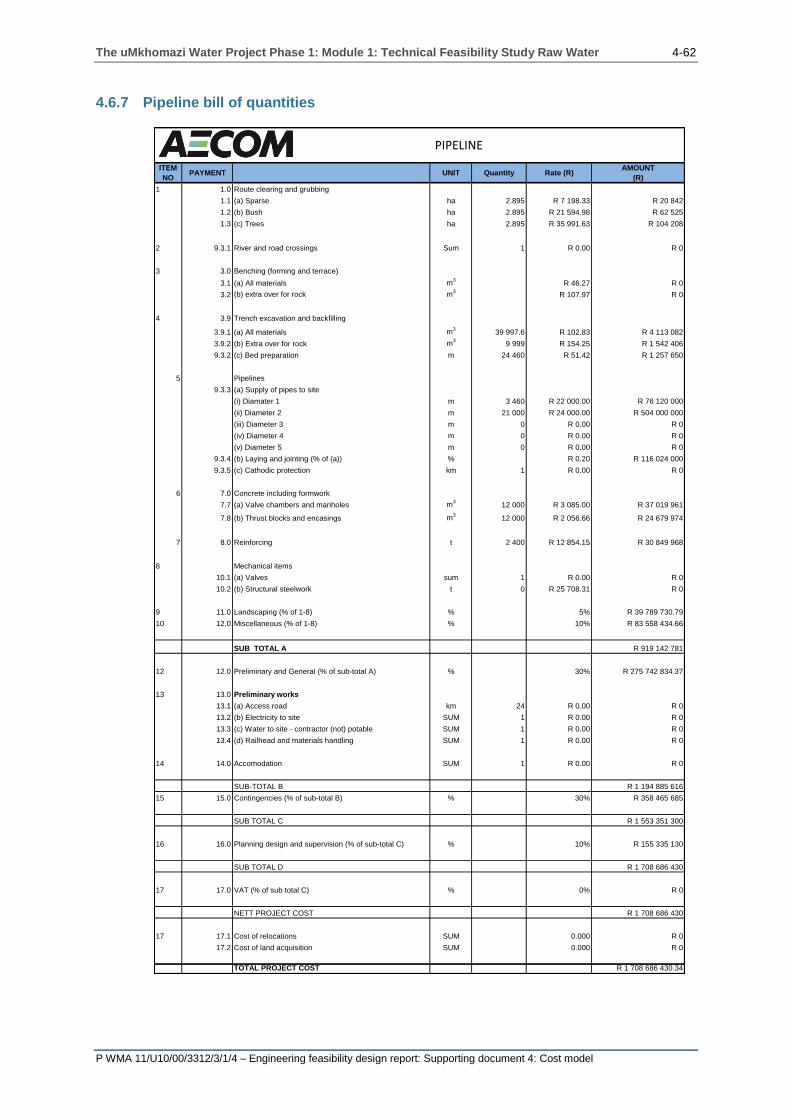
The uMkhomazi Water Project Phase 1: Module 1: Technical Feasibility Study Raw Water 4-62
P WMA 11/U10/00/3312/3/1/4 – Engineering feasibility design report: Supporting document 4: Cost model
4.6.7 Pipeline bill of quantities
ITEM
NOPAYMENT UNIT Quantity Rate (R)
AMOUNT
(R)
1 1.0 Route clearing and grubbing
1.1 (a) Sparse ha 2.895 R 7 198.33 R 20 842
1.2 (b) Bush ha 2.895 R 21 594.98 R 62 525
1.3 (c) Trees ha 2.895 R 35 991.63 R 104 208
2 9.3.1 River and road crossings Sum 1 R 0.00 R 0
3 3.0 Benching (forming and terrace)
3.1 (a) All materials m3
R 46.27 R 0
3.2 (b) extra over for rock m3
R 107.97 R 0
4 3.9 Trench excavation and backfilling
3.9.1 (a) All materials m3
39 997.6 R 102.83 R 4 113 082
3.9.2 (b) Extra over for rock m3
9 999 R 154.25 R 1 542 406
9.3.2 (c) Bed preparation m 24 460 R 51.42 R 1 257 650
5 Pipelines
9.3.3 (a) Supply of pipes to site
(i) Diamater 1 m 3 460 R 22 000.00 R 76 120 000
(ii) Diameter 2 m 21 000 R 24 000.00 R 504 000 000
(iii) Diameter 3 m 0 R 0.00 R 0
(iv) Diameter 4 m 0 R 0.00 R 0
(v) Diameter 5 m 0 R 0.00 R 0
9.3.4 (b) Laying and jointing (% of (a)) % R 0.20 R 116 024 000
9.3.5 (c) Cathodic protection km 1 R 0.00 R 0
6 7.0 Concrete including formwork
7.7 (a) Valve chambers and manholes m3
12 000 R 3 085.00 R 37 019 961
7.8 (b) Thrust blocks and encasings m3
12 000 R 2 056.66 R 24 679 974
7 8.0 Reinforcing t 2 400 R 12 854.15 R 30 849 968
8 Mechanical items
10.1 (a) Valves sum 1 R 0.00 R 0
10.2 (b) Structural steelwork t 0 R 25 708.31 R 0
9 11.0 Landscaping (% of 1-8) % 5% R 39 789 730.79
10 12.0 Miscellaneous (% of 1-8) % 10% R 83 558 434.66
SUB TOTAL A R 919 142 781
12 12.0 Preliminary and General (% of sub-total A) % 30% R 275 742 834.37
13 13.0 Preliminary works
13.1 (a) Access road km 24 R 0.00 R 0
13.2 (b) Electricity to site SUM 1 R 0.00 R 0
13.3 (c) Water to site - contractor (not) potable SUM 1 R 0.00 R 0
13.4 (d) Railhead and materials handling SUM 1 R 0.00 R 0
14 14.0 Accomodation SUM 1 R 0.00 R 0
SUB-TOTAL B R 1 194 885 616
15 15.0 Contingencies (% of sub-total B) % 30% R 358 465 685
SUB TOTAL C R 1 553 351 300
16 16.0 Planning design and supervision (% of sub-total C) % 10% R 155 335 130
SUB TOTAL D R 1 708 686 430
17 17.0 VAT (% of sub total C) % 0% R 0
NETT PROJECT COST R 1 708 686 430
17 17.1 Cost of relocations SUM 0.000 R 0
17.2 Cost of land acquisition SUM 0.000 R 0
TOTAL PROJECT COST R 1 708 686 430.34
PIPELINE

The uMkhomazi Water Project Phase 1: Module 1: Technical Feasibility Study Raw Water 4-63
P WMA 11/U10/00/3312/3/1/4 – Engineering feasibility design report: Supporting document 4: Cost model
4.7 SUMMARY SHEET
The cost breakdown sheet enables the addition of social, environmental and
administrative costs including the preliminary and general costs related to the dam
construction site. All cells highlighted in yellow require an input value.
4.7.1 Dam summary sheet
Figure 4.30 shows the summary sheet for all the components related to the dam.
Figure 4.30: Dam cost summary sheet
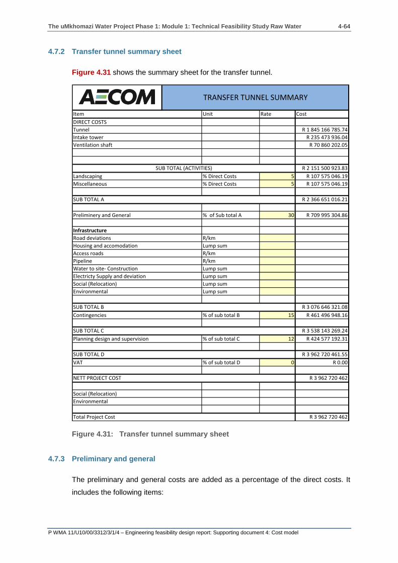
The uMkhomazi Water Project Phase 1: Module 1: Technical Feasibility Study Raw Water 4-64
P WMA 11/U10/00/3312/3/1/4 – Engineering feasibility design report: Supporting document 4: Cost model
4.7.2 Transfer tunnel summary sheet
Figure 4.31 shows the summary sheet for the transfer tunnel.
Figure 4.31: Transfer tunnel summary sheet
4.7.3 Preliminary and general
The preliminary and general costs are added as a percentage of the direct costs. It
includes the following items:
Item Unit Rate Cost
DIRECT COSTS
Tunnel R 1 845 166 785.74
Intake tower R 235 473 936.04
Ventilation shaft R 70 860 202.05
R 2 151 500 923.83
Landscaping % Direct Costs 5 R 107 575 046.19
Miscellaneous % Direct Costs 5 R 107 575 046.19
R 2 366 651 016.21
Preliminery and General % of Sub total A 30 R 709 995 304.86
Infrastructure
Road deviations R/km
Housing and accomodation Lump sum
Access roads R/km
Pipeline R/km
Water to site- Construction Lump sum
Electricty Supply and deviation Lump sum
Social (Relocation) Lump sum
Environmental Lump sum
R 3 076 646 321.08
Contingencies % of sub total B 15 R 461 496 948.16
R 3 538 143 269.24
Planning design and supervision % of sub total C 12 R 424 577 192.31
R 3 962 720 461.55
VAT % of sub total D 0 R 0.00
R 3 962 720 462
Social (Relocation)
Environmental
R 3 962 720 462Total Project Cost
TRANSFER TUNNEL SUMMARY
SUB TOTAL (ACTIVITIES)
SUB TOTAL A
SUB TOTAL B
SUB TOTAL C
SUB TOTAL D
NETT PROJECT COST

The uMkhomazi Water Project Phase 1: Module 1: Technical Feasibility Study Raw Water 4-65
P WMA 11/U10/00/3312/3/1/4 – Engineering feasibility design report: Supporting document 4: Cost model
Road deviations;
Housing and accommodation;
Access roads;
Additional pipelines;
Water to site – Construction;
Electricity supply and deviation;
Social (Relocation); and
Environmental.
If the costs of these items are unknown, the percentage for P&Gs may be increased
else if the costs of these items are known, they can be inserted in this column.
The unit for preliminary and general is percentage (%).
4.7.4 Preliminary works
If these items are not included in the preliminary and general costs, then these items
need to be separately cost and inserted in the required cell. These items can vary
depending on the configuration of the infrastructure related to the dam project and
therefore could have an effect on the final cost of the project.
4.7.5 Road deviations and access roads
These items include all roads that need to be constructed or upgraded in order to
provide access to the site. Roads that will be inundated by water during
impoundment will need to be diverted. The access roads are usually gravel surfaced
all-weather roads which are 5 to 6 m wide. The cost should include all earthworks,
layer works, drainage and fences that need to be constructed.
The unit for access roads is kilometres (km).
4.7.6 Electricity supply to site
For each dam project the electricity supply to site differs and therefore a generic
formula cannot be used. The unit for electricity supply to site is a lump sum.
The uMkhomazi Water Project Phase 1: Module 1: Technical Feasibility Study Raw Water 4-66
P WMA 11/U10/00/3312/3/1/4 – Engineering feasibility design report: Supporting document 4: Cost model
4.7.7 Construction water to site
The quantity of water required differs for each project regarding the requirements for
the dam site, canals or tunnels. Water may be extracted from the river, however the
additional cost of pipelines and pumps need to be considered.
4.7.8 Accommodation
Provision needs to be made for the accommodation of on-site personnel, which
includes all supervisory and contracted staff. Dam sites are usually located in remote
areas with limited access to established settlements and therefore the extent to which
permanent and temporary accommodation would need to be constructed will depend
on the surrounding environment and resources.
The unit for accommodation is a lump sum.
4.7.9 Contingencies
The allowance for all project costs due to unforeseen circumstances, claims and
extra work is allowed for as a percentage of the total cost of direct and indirect work
excluding the professional and consulting fees.
4.7.10 Planning design and supervision
The cost of consulting engineer’s fees is allowed as a percentage of the total of the
direct and indirect work.
The unit for planning, design and supervision is percentage (%).
4.7.11 Value added tax (VAT)
Value added tax is added as a percentage of the total cost of direct and indirect work
and consulting fees. In most instances, VAT is excluded because it does not
significantly represent the cost of the project, particularly if it is a public project.
The unit for VAT is percentage (%).
The uMkhomazi Water Project Phase 1: Module 1: Technical Feasibility Study Raw Water 4-67
P WMA 11/U10/00/3312/3/1/4 – Engineering feasibility design report: Supporting document 4: Cost model
4.7.12 Cost of relocations
Additional social costs related to the relocation of residents within the dam basin can
be inserted within this cell.
The unit for relocation of services and accommodation shall be a lump sum.
4.7.13 Cost of land acquisition
Land owners within the dam basin will need to be compensated for their land that is
going to be inundated with water. Such compensation will need to be assessed at
both the reconnaissance and prefeasibility stage in order for financial allowances to
be made.

The uMkhomazi Water Project Phase 1: Module 1: Technical Feasibility Study Raw Water 5-1
P WMA 11/U10/00/3312/3/1/4 – Engineering feasibility design report: Supporting document 4: Cost model
5 TECHNICAL INFORMATION
This section of the report provides a more in-depth explanation on how the quantities
are determined within the calculation spreadsheets. The technical information should
be used with the Cost Model Excel Spreadsheet.
5.1 ROLLER COMPACTED CONCRETE DAM
A roller compacted concrete gravity dam is entirely dependent upon its own mass for
stability. The gravity profile is essentially triangular, with an outline geometry
indicated on Figure 5.1, to ensure stability and to avoid overstressing of the dam or
its foundation. Roller compacted concrete is defined by the American Concrete
Institute (RCC) as “concrete compacted by roller compaction; concrete that, in its
unhardened state, will support a roller while being compacted.” RCC use within dam
construction is ideal as it involves large placement areas, with little or no
reinforcement and a lower cost on the concrete.
Figure 5.1: Roller compacted concrete gravity dam
Figure 5.2 shows a section of the calculation spreadsheet for the determination of
the quantities of a roller compacted concrete dam.

The uMkhomazi Water Project Phase 1: Module 1: Technical Feasibility Study Raw Water 5-2
P WMA 11/U10/00/3312/3/1/4 – Engineering feasibility design report: Supporting document 4: Cost model
Figure 5.2: Calculation spreadsheet section for roller compacted concrete dam
Ogee length 160 m 80 3600 3520 3680
1 2 3 4 5 6 7 8 9 10 11 12 13 14 15 16 17 18 19 20 21
Foundation
Section NGL NOC FSL Excavation Section interval
Crest
width
Downstream
slope
Upstream
slope
Excavation
Slope
NGL
Width
of
base
Excavated Base
width
Footprint area
at NGL
(Horizontal)
Topsoil
Excavation
Area
(Vertical)
Excavated
volume Area 1 Area 2 Area 3 Total Volume Preparation
1 masl masl (m) (m) (m) (M:1) (M:1) (M:1) m m m2 m2 m3 m2 m2 m2 m2m3 m2
1 0.000 0 0.0 0.0 0.0 0.0 0.0 0.0 0.0 0.0 0.0 0.0 0.0 0.0 0.0 0.0 0.0
2 0.0 0 0.0 0.0 0.0 0.0 0.0 0.0 0.0 0.0 0.0 0.0 0.0 0.0 0.0 0.0 0.0 0.0 0.0 0.0
3 0.0 0 0.0 0.0 0.0 0.0 0.0 0.0 0.0 0.0 0.0 0.0 0.0 0.0 0.0 0.0 0.0 0.0 0.0 0.0
4 0.0 0 0.0 0.0 0.0 0.0 0.0 0.0 0.0 0.0 0.0 0.0 0.0 0.0 0.0 0.0 0.0 0.0 0.0 0.0
5 0.0 0 0.0 0.0 0.0 0.0 0.0 0.0 0.0 0.0 0.0 0.0 0.0 0.0 0.0 0.0 0.0 0.0 0.0 0.0
6 0.0 0 0.0 0.0 0.0 0.0 0.0 0.0 0.0 0.0 0.0 0.0 0.0 0.0 0.0 0.0 0.0 0.0 0.0 0.0
7 0.0 0 0.0 0.0 0.0 0.0 0.0 0.0 0.0 0.0 0.0 0.0 0.0 0.0 0.0 0.0 0.0 0.0 0.0 0.0
Excavatiuon Volume concrete
ROLLER COMPACTED CONCRETE DAM
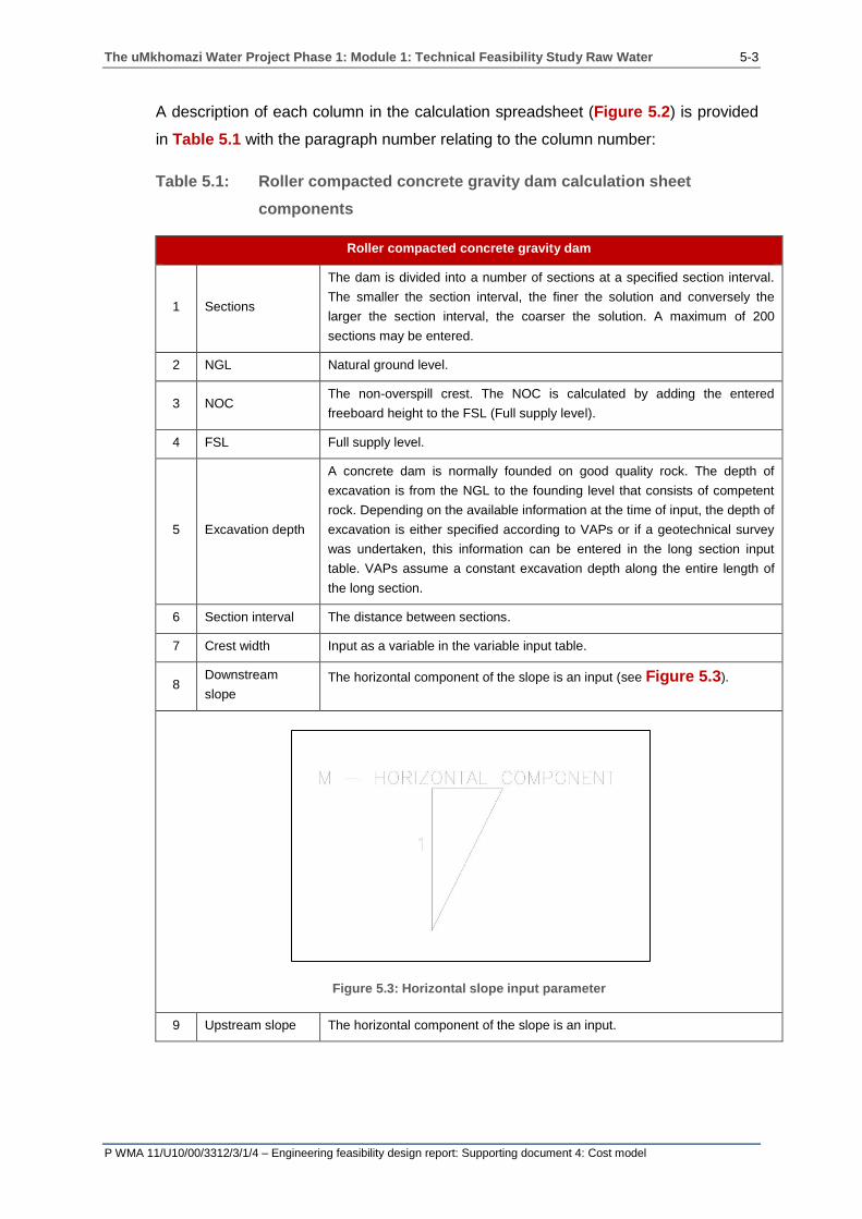
The uMkhomazi Water Project Phase 1: Module 1: Technical Feasibility Study Raw Water 5-3
P WMA 11/U10/00/3312/3/1/4 – Engineering feasibility design report: Supporting document 4: Cost model
A description of each column in the calculation spreadsheet (Figure 5.2) is provided
in Table 5.1 with the paragraph number relating to the column number:
Table 5.1: Roller compacted concrete gravity dam calculation sheet
components
Roller compacted concrete gravity dam
1 Sections
The dam is divided into a number of sections at a specified section interval.
The smaller the section interval, the finer the solution and conversely the
larger the section interval, the coarser the solution. A maximum of 200
sections may be entered.
2 NGL Natural ground level.
3 NOC The non-overspill crest. The NOC is calculated by adding the entered
freeboard height to the FSL (Full supply level).
4 FSL Full supply level.
5 Excavation depth
A concrete dam is normally founded on good quality rock. The depth of
excavation is from the NGL to the founding level that consists of competent
rock. Depending on the available information at the time of input, the depth of
excavation is either specified according to VAPs or if a geotechnical survey
was undertaken, this information can be entered in the long section input
table. VAPs assume a constant excavation depth along the entire length of
the long section.
6 Section interval The distance between sections.
7 Crest width Input as a variable in the variable input table.
8 Downstream
slope
The horizontal component of the slope is an input (see Figure 5.3).
Figure 5.3: Horizontal slope input parameter
9 Upstream slope The horizontal component of the slope is an input.

The uMkhomazi Water Project Phase 1: Module 1: Technical Feasibility Study Raw Water 5-4
P WMA 11/U10/00/3312/3/1/4 – Engineering feasibility design report: Supporting document 4: Cost model
10 Excavation slope. The batter slope of the foundation excavation.
11 NGL width at
base:
Surface width parallel to a section, including the horizontal component of the
upstream and downstream batter slopes.
12 Excavated base
width:
The horizontal length of the base parallel to a section at the excavation depth
and excludes the horizontal component of the upstream and downstream
batter slopes.
13 Footprint area at
NGL:
The area at NGL level calculated between two sections using the trapezoidal
rule (see Figure 5.4);
𝑨𝒓𝒆𝒂
= ∑[[𝒔𝒆𝒄𝒕𝒊𝒐𝒏(𝑵) + 𝒔𝒆𝒄𝒕𝒊𝒐𝒏(𝑵 + 𝟏)]
𝟐][𝑺𝒆𝒄𝒕𝒊𝒐𝒏 𝒊𝒏𝒕𝒆𝒓𝒗𝒂𝒍(𝑵)]
𝒏
𝑵=𝟏
(3.1.1)
Figure 5.4: Section interval
14
Topsoil
Excavation Area
(Vertical)
The area calculated per section using column [5], [11] and [12]. Calculated
using the trapezoidal rule;
𝑨𝒓𝒆𝒂 = [[𝟏𝟏] + [𝟏𝟐]][[𝟓]
𝟐]
(3.1.2)
15 Excavated volume The volume of material that needs to be excavated in order to
reach the founding depth.
16 Area 1 The upstream triangular section of the section view.
17 Area 2 The central rectangular section comprising of the crest width and height
between the NOC and the excavation line.
18 Area 3 The downstream triangular section of the sectional view.
19 Total
The total cross sectional area at each section;
𝑻𝒐𝒕𝒂𝒍 = 𝑨𝒓𝒆𝒂 𝟏 + 𝑨𝒓𝒆𝒂 𝟐 + 𝑨𝒓𝒆𝒂 𝟑 (3.1.3)
20 Volume The volume of concrete calculated using the trapezoidal rule (see
Figure 5.5).
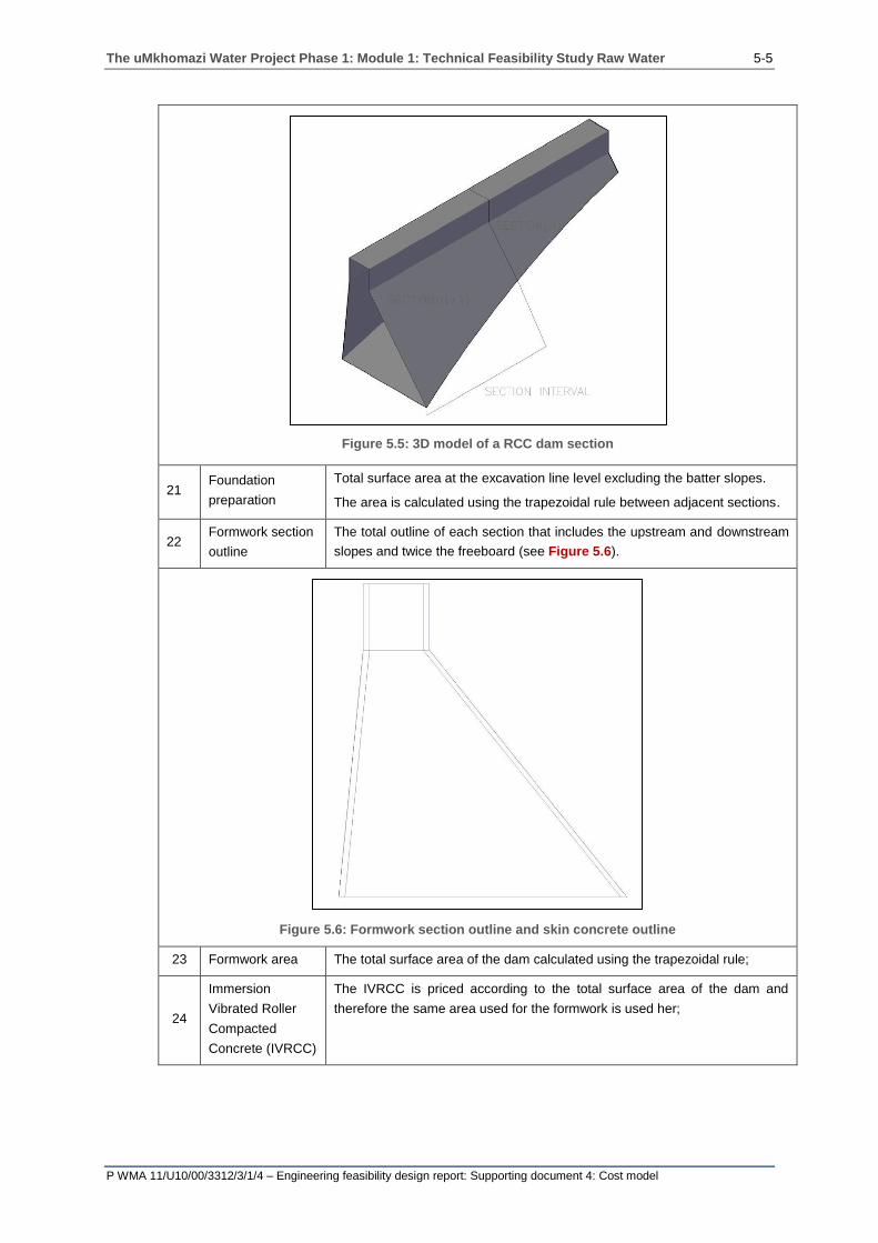
The uMkhomazi Water Project Phase 1: Module 1: Technical Feasibility Study Raw Water 5-5
P WMA 11/U10/00/3312/3/1/4 – Engineering feasibility design report: Supporting document 4: Cost model
Figure 5.5: 3D model of a RCC dam section
21 Foundation
preparation
Total surface area at the excavation line level excluding the batter slopes.
The area is calculated using the trapezoidal rule between adjacent sections.
22 Formwork section
outline
The total outline of each section that includes the upstream and downstream
slopes and twice the freeboard (see Figure 5.6).
Figure 5.6: Formwork section outline and skin concrete outline
23 Formwork area The total surface area of the dam calculated using the trapezoidal rule;
24
Immersion
Vibrated Roller
Compacted
Concrete (IVRCC)
The IVRCC is priced according to the total surface area of the dam and
therefore the same area used for the formwork is used her;
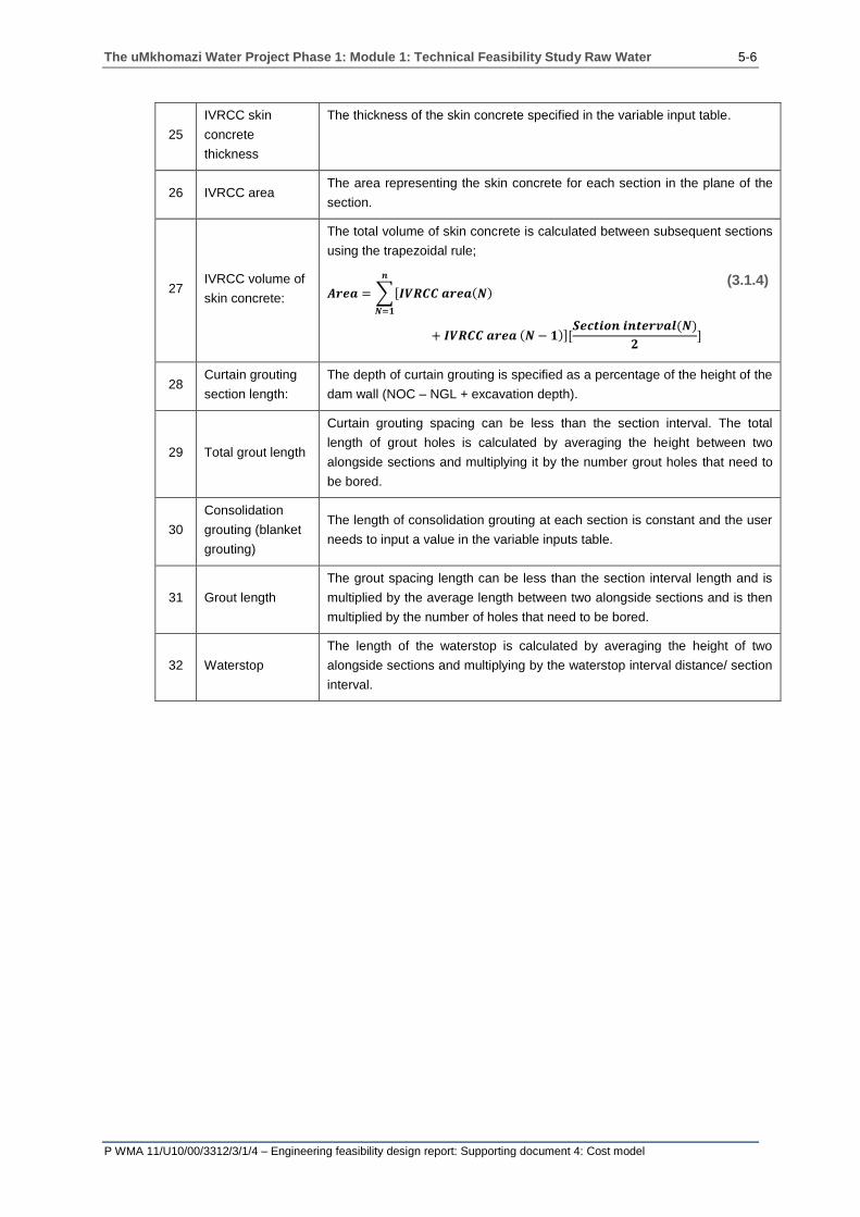
The uMkhomazi Water Project Phase 1: Module 1: Technical Feasibility Study Raw Water 5-6
P WMA 11/U10/00/3312/3/1/4 – Engineering feasibility design report: Supporting document 4: Cost model
25
IVRCC skin
concrete
thickness
The thickness of the skin concrete specified in the variable input table.
26 IVRCC area The area representing the skin concrete for each section in the plane of the
section.
27 IVRCC volume of
skin concrete:
The total volume of skin concrete is calculated between subsequent sections
using the trapezoidal rule;
𝑨𝒓𝒆𝒂 = ∑[𝑰𝑽𝑹𝑪𝑪 𝒂𝒓𝒆𝒂(𝑵)
𝒏
𝑵=𝟏
+ 𝑰𝑽𝑹𝑪𝑪 𝒂𝒓𝒆𝒂 (𝑵 − 𝟏)][𝑺𝒆𝒄𝒕𝒊𝒐𝒏 𝒊𝒏𝒕𝒆𝒓𝒗𝒂𝒍(𝑵)
𝟐]
(3.1.4)
28 Curtain grouting
section length:
The depth of curtain grouting is specified as a percentage of the height of the
dam wall (NOC – NGL + excavation depth).
29 Total grout length
Curtain grouting spacing can be less than the section interval. The total
length of grout holes is calculated by averaging the height between two
alongside sections and multiplying it by the number grout holes that need to
be bored.
30
Consolidation
grouting (blanket
grouting)
The length of consolidation grouting at each section is constant and the user
needs to input a value in the variable inputs table.
31 Grout length
The grout spacing length can be less than the section interval length and is
multiplied by the average length between two alongside sections and is then
multiplied by the number of holes that need to be bored.
32 Waterstop
The length of the waterstop is calculated by averaging the height of two
alongside sections and multiplying by the waterstop interval distance/ section
interval.
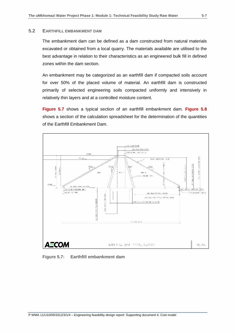
The uMkhomazi Water Project Phase 1: Module 1: Technical Feasibility Study Raw Water 5-7
P WMA 11/U10/00/3312/3/1/4 – Engineering feasibility design report: Supporting document 4: Cost model
5.2 EARTHFILL EMBANKMENT DAM
The embankment dam can be defined as a dam constructed from natural materials
excavated or obtained from a local quarry. The materials available are utilised to the
best advantage in relation to their characteristics as an engineered bulk fill in defined
zones within the dam section.
An embankment may be categorized as an earthfill dam if compacted soils account
for over 50% of the placed volume of material. An earthfill dam is constructed
primarily of selected engineering soils compacted uniformly and intensively in
relatively thin layers and at a controlled moisture content.
Figure 5.7 shows a typical section of an earthfill embankment dam. Figure 5.8
shows a section of the calculation spreadsheet for the determination of the quantities
of the Earthfill Embankment Dam.
Figure 5.7: Earthfill embankment dam
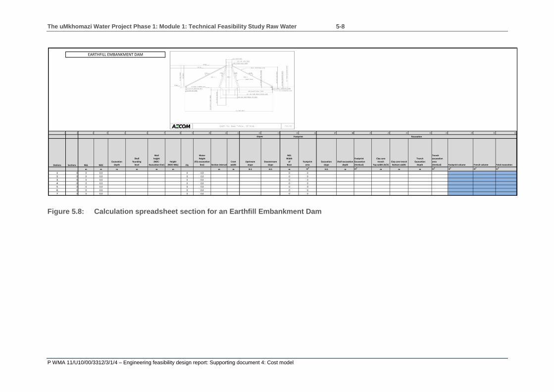
The uMkhomazi Water Project Phase 1: Module 1: Technical Feasibility Study Raw Water 5-8
P WMA 11/U10/00/3312/3/1/4 – Engineering feasibility design report: Supporting document 4: Cost model
Figure 5.8: Calculation spreadsheet section for an Earthfill Embankment Dam
1 2 3 4 5 6 7 8 9 10 11 12 13 14 15 16 17 18 19 20 21 22 23 24 25 26
Stations Sections NGL NOC
Excavation
depth
Shell
founding
level
Wall
height
(NOC-
Excavation line)
Height
(NOC-NGL) FSL
Water
Height
(FSL-excavation
line) Section interval
Crest
width
Upstream
slope
Downstream
slope
NGL
Width
of
Base
Footprint
area
Excavation
slope
Shell excavation
depth
Footprint
Excavation
(Vertical)
Clay core
trench
Top width (H/2)
Clay core trench
Bottom width
Trench
Excavation
Depth
Trench
excavation
area
(Vertical) Footprint volume Trench volume Total excavation
m m m m m m m m H:1 H:1 m m2H:1 m m2
m m m m2 m3 m3 m3
1 0 0 0.0 0 0.0 0 0
2 0 0 0.0 0 0.0 0 0
3 0 0 0.0 0 0.0 0 0
4 0 0 0.0 0 0.0 0 0
5 0 0 0.0 0 0.0 0 0
6 0 0 0.0 0 0.0 0 0
7 0 0 0.0 0 0.0 0 0
Excavation
EARTHFILL EMBANKMENT DAM
Embankment
slopes Footprint
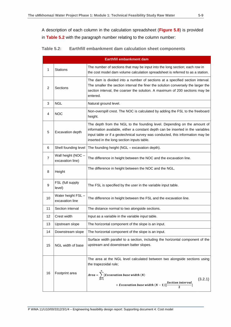
The uMkhomazi Water Project Phase 1: Module 1: Technical Feasibility Study Raw Water 5-9
P WMA 11/U10/00/3312/3/1/4 – Engineering feasibility design report: Supporting document 4: Cost model
A description of each column in the calculation spreadsheet (Figure 5.8) is provided
in Table 5.2 with the paragraph number relating to the column number:
Table 5.2: Earthfill embankment dam calculation sheet components
Earthfill embankment dam
1 Stations The number of sections that may be input into the long section; each row in
the cost model dam volume calculation spreadsheet is referred to as a station.
2 Sections
The dam is divided into a number of sections at a specified section interval.
The smaller the section interval the finer the solution conversely the larger the
section interval, the coarser the solution. A maximum of 200 sections may be
entered.
3 NGL Natural ground level.
4 NOC Non-overspill crest. The NOC is calculated by adding the FSL to the freeboard
height.
5 Excavation depth
The depth from the NGL to the founding level. Depending on the amount of
information available, either a constant depth can be inserted in the variables
input table or if a geotechnical survey was conducted, this information may be
inserted in the long section inputs table.
6 Shell founding level The founding height (NGL – excavation depth).
7 Wall height (NOC –
excavation line) The difference in height between the NOC and the excavation line.
8 Height The difference in height between the NOC and the NGL.
9 FSL (full supply
level) The FSL is specified by the user in the variable input table.
10 Water height FSL –
excavation line The difference in height between the FSL and the excavation line.
11 Section interval The distance normal to two alongside sections.
12 Crest width Input as a variable in the variable input table.
13 Upstream slope The horizontal component of the slope is an input.
14 Downstream slope The horizontal component of the slope is an input.
15 NGL width of base
Surface width parallel to a section, including the horizontal component of the
upstream and downstream batter slopes.
16 Footprint area
The area at the NGL level calculated between two alongside sections using
the trapezoidal rule;
𝑨𝒓𝒆𝒂 = ∑[𝑬𝒙𝒄𝒂𝒗𝒂𝒕𝒊𝒐𝒏 𝒃𝒂𝒔𝒆 𝒘𝒊𝒅𝒕𝒉 (𝑵)
𝒏
𝑵=𝟏
+ 𝑬𝒙𝒄𝒂𝒗𝒂𝒕𝒊𝒐𝒏 𝒃𝒂𝒔𝒆 𝒘𝒊𝒅𝒕𝒉 (𝑵 − 𝟏)][𝑺𝒆𝒄𝒕𝒊𝒐𝒏 𝒊𝒏𝒕𝒆𝒓𝒗𝒂𝒍
𝟐]
(3.2.1)
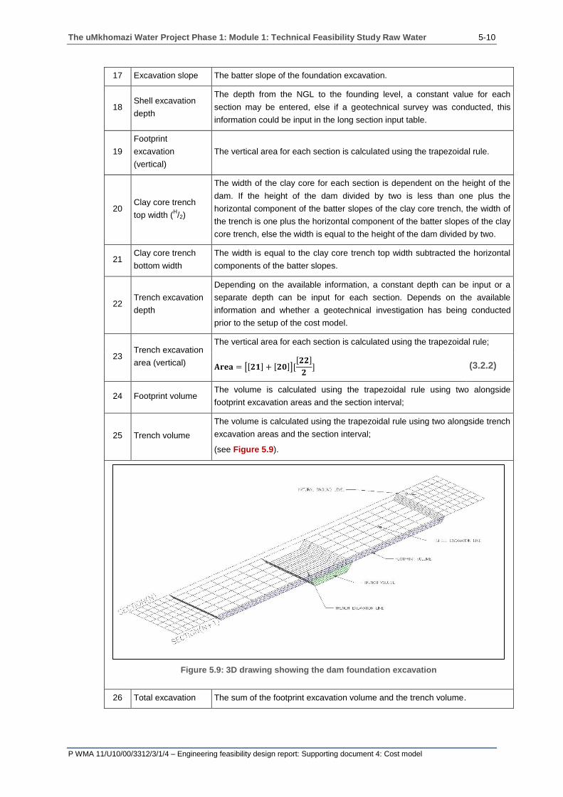
The uMkhomazi Water Project Phase 1: Module 1: Technical Feasibility Study Raw Water 5-10
P WMA 11/U10/00/3312/3/1/4 – Engineering feasibility design report: Supporting document 4: Cost model
17 Excavation slope The batter slope of the foundation excavation.
18 Shell excavation
depth
The depth from the NGL to the founding level, a constant value for each
section may be entered, else if a geotechnical survey was conducted, this
information could be input in the long section input table.
19
Footprint
excavation
(vertical)
The vertical area for each section is calculated using the trapezoidal rule.
20 Clay core trench
top width (H/2)
The width of the clay core for each section is dependent on the height of the
dam. If the height of the dam divided by two is less than one plus the
horizontal component of the batter slopes of the clay core trench, the width of
the trench is one plus the horizontal component of the batter slopes of the clay
core trench, else the width is equal to the height of the dam divided by two.
21 Clay core trench
bottom width
The width is equal to the clay core trench top width subtracted the horizontal
components of the batter slopes.
22 Trench excavation
depth
Depending on the available information, a constant depth can be input or a
separate depth can be input for each section. Depends on the available
information and whether a geotechnical investigation has being conducted
prior to the setup of the cost model.
23 Trench excavation
area (vertical)
The vertical area for each section is calculated using the trapezoidal rule;
𝐀𝐫𝐞𝐚 = [[𝟐𝟏] + [𝟐𝟎]][[𝟐𝟐]
𝟐] (3.2.2)
24 Footprint volume The volume is calculated using the trapezoidal rule using two alongside
footprint excavation areas and the section interval;
25 Trench volume
The volume is calculated using the trapezoidal rule using two alongside trench
excavation areas and the section interval;
(see Figure 5.9).
Figure 5.9: 3D drawing showing the dam foundation excavation
26 Total excavation The sum of the footprint excavation volume and the trench volume.
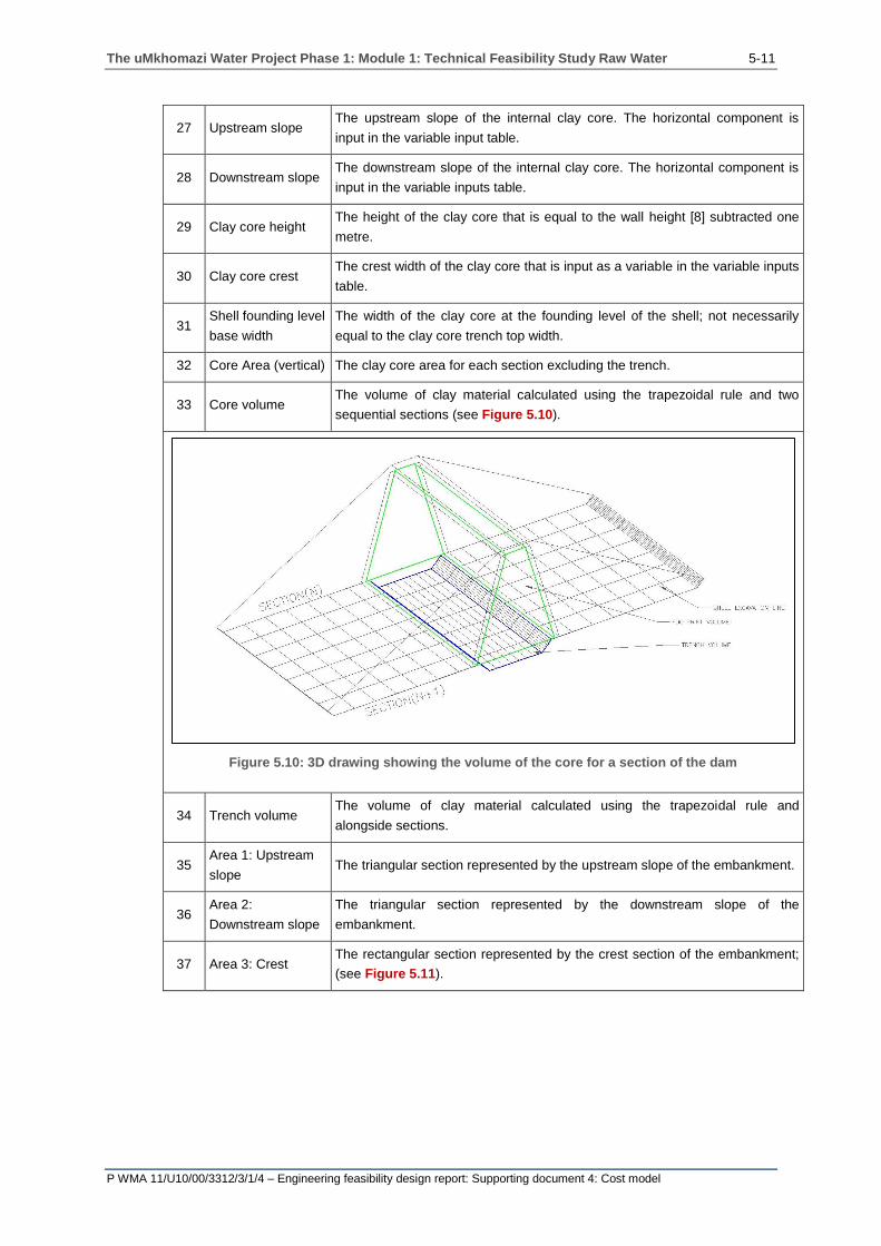
The uMkhomazi Water Project Phase 1: Module 1: Technical Feasibility Study Raw Water 5-11
P WMA 11/U10/00/3312/3/1/4 – Engineering feasibility design report: Supporting document 4: Cost model
27 Upstream slope The upstream slope of the internal clay core. The horizontal component is
input in the variable input table.
28 Downstream slope The downstream slope of the internal clay core. The horizontal component is
input in the variable inputs table.
29 Clay core height The height of the clay core that is equal to the wall height [8] subtracted one
metre.
30 Clay core crest The crest width of the clay core that is input as a variable in the variable inputs
table.
31 Shell founding level
base width
The width of the clay core at the founding level of the shell; not necessarily
equal to the clay core trench top width.
32 Core Area (vertical) The clay core area for each section excluding the trench.
33 Core volume The volume of clay material calculated using the trapezoidal rule and two
sequential sections (see Figure 5.10).
Figure 5.10: 3D drawing showing the volume of the core for a section of the dam
34 Trench volume The volume of clay material calculated using the trapezoidal rule and
alongside sections.
35 Area 1: Upstream
slope The triangular section represented by the upstream slope of the embankment.
36 Area 2:
Downstream slope
The triangular section represented by the downstream slope of the
embankment.
37 Area 3: Crest The rectangular section represented by the crest section of the embankment;
(see Figure 5.11).

The uMkhomazi Water Project Phase 1: Module 1: Technical Feasibility Study Raw Water 5-12
P WMA 11/U10/00/3312/3/1/4 – Engineering feasibility design report: Supporting document 4: Cost model
Figure 5.11: Shows the three areas used to calculate the total cross sectional area
38 Total cross
sectional area
Summation of Area 1: Upstream slope, Area 2: Downstream slope and Area 3:
Crest to get the total area for each cross section.
39 Rip-rap width The horizontal width of the upstream rip-rap layer.
40 Rip-rap cross
sectional area The vertical cross sectional area of rip-rap for each section of the dam.
41 Rip-rap volume The volume of rip-rap calculated using the trapezoidal rule using two
sequential sections (see Figure 5.12).
Figure 5.12: 3D illustration of a section of the upstream rip-rap layer
42 Gravel horizontal
width
The horizontal width specified for each section for the gravel protection layer
on the downstream slope of the dam.
43 Gravel cross
sectional area
The vertical cross sectional area in the plane of the section calculated for each
section of the dam.
44 Gravel protection
volume
The volume of gravel calculated using two alongside sections using the
trapezoidal rule.

The uMkhomazi Water Project Phase 1: Module 1: Technical Feasibility Study Raw Water 5-13
P WMA 11/U10/00/3312/3/1/4 – Engineering feasibility design report: Supporting document 4: Cost model
45 Filters transition
width
The horizontal width specified for each section for the filters on the upstream
slope of the dam. If the upstream filter consists of a number of layers, the total
width is input and the subsequent volume of material can be proportioned
according to the thickness of each layer (see Figure 5.13);
𝑽𝟏 + 𝑽𝟐 + ⋯ + 𝑽𝒏 = 𝑽𝒕 (3.2.2.1)
𝑭𝟏
𝑭𝟏 + 𝑭𝟐 + ⋯ + 𝑭𝒏. 𝑽𝒕 = 𝑽𝟏
(3.2.2.2)
𝑭𝟐
𝑭𝟏 + 𝑭𝟐 + ⋯ + 𝑭𝒏. 𝑽𝒕 = 𝑽𝟐
(3.2.2.3)
𝑭𝒏
𝑭𝟏 + 𝑭𝟐 + ⋯ + 𝑭𝒏. 𝑽𝒕 = 𝑽𝒏
(3.2.2.4)
Where:
Vt = Total volume of filter transition material
V1 = Volume of filter transition material for layer one
V2 = Volume of filter transition material for layer two
Vn = Volume of filter transition material for layer n
F1 = Horizontal thickness of layer one
F2 = Horizontal width of layer two
Fn = Horizontal width of layer n
Figure 5.13: Upstream filter transition layer

The uMkhomazi Water Project Phase 1: Module 1: Technical Feasibility Study Raw Water 5-14
P WMA 11/U10/00/3312/3/1/4 – Engineering feasibility design report: Supporting document 4: Cost model
46 Transition cross
sectional area
The cross sectional area calculated for each section of the dam filter
material.
47 Transition volume The volume of filter material calculated using two alongside sections using
the trapezoidal rule.
48 Chimney drain
horizontal width
The horizontal width specified for each section of chimney drain downstream
of the clay core.
49 Clay core height The height of the clay core that is equal to the wall height subtracted [8] one
(as per [29]).
50 Chimney drain cross
sectional area
The cross sectional area of the chimney drain calculated for each section of
the dam.
51 Chimney drain
material volume
The volume of filter material for the chimney drain calculated using two
alongside sections using the trapezoidal rule.
52 Blanket drain
thickness
The vertical thickness of the blanket specified as a variable input in the
variable input table.
53 Blanket drain length The length of the blanket drain calculated as the distance between the
downstream toe of the clay core and the downstream toe of the dam.
54 Blanket drain area The cross sectional area calculated for each section of the dam. Calculated
by multiplying the blanket drain thickness and the blanket drain length.
55 Blanket drain
material volume
The volume of filter material for the blanket drain calculated using two
alongside sections using the trapezoidal rule.
56 Crest width As per number column [12]. Input as a variable in the variable inputs table.
57 Footprint width Equal to the sum of the horizontal components of the upstream and
downstream slopes including the crest of the dam for each section;
58 Shell cross sectional
area
Total cross sectional area of the shell material. It can be seen that the area
is calculated by subtracting the clay core area, upstream filter area and the
downstream chimney and blanket drain area.
59 Total shell volume The volume of material is calculated by using the trapezoidal rule and two
alongside sections and the section interval.
60
Foundation
preparation section
width
The sum of the horizontal components of the upstream and downstream
slopes and the crest excluding the batter slopes.
61
Foundation
preparation
horizontal area
The foundation surface area is calculated at the excavation line. The area is
determined using the trapezoidal rule by using two alongside foundation
preparation section widths and the sectional interval;
62 Curtain grouting
The length of the curtain grouting is calculated as a percentage (input in the
variable inputs table) of the height of the dam. The grout spacing is entered
as a variable in the variable input table. The total length of curtain grouting is
calculated by averaging two alongside grout depths and multiplying it by the
number of intervals, which is determined by dividing the section interval by
the grout spacing (see Figure 5.14);
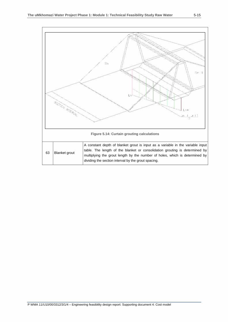
The uMkhomazi Water Project Phase 1: Module 1: Technical Feasibility Study Raw Water 5-15
P WMA 11/U10/00/3312/3/1/4 – Engineering feasibility design report: Supporting document 4: Cost model
Figure 5.14: Curtain grouting calculations
63 Blanket grout
A constant depth of blanket grout is input as a variable in the variable input
table. The length of the blanket or consolidation grouting is determined by
multiplying the grout length by the number of holes, which is determined by
dividing the section interval by the grout spacing.

The uMkhomazi Water Project Phase 1: Module 1: Technical Feasibility Study Raw Water 5-16
P WMA 11/U10/00/3312/3/1/4 – Engineering feasibility design report: Supporting document 4: Cost model
5.3 EARTH CORE ROCKFILL EMBANKMENT DAM
The embankment dam can be defined as a dam constructed from natural materials
excavated or obtained from a local quarry. The materials available are utilised to the
best advantage in relation to their characteristics as an engineered bulk fill in defined
zones within the dam section.
In the rockfill embankment the section includes a discrete element of compacted
earthfill often with a number of transition layers between the clay core material and
the rockfill material. The designation rockfill embankment is appropriate where over
50% of the fill material may be classified as rockfill, i.e. coarse-grained frictional
material. Rockfill embankment dams often result in having slopes that are steeper in
comparison with the earthfill embankment dam as a result of a higher angle of
internal friction. The steeper slopes often results in lower material volumes that could
result in lower costs.
Figure 5.15 shows a typical section of an earth core rockfill embankment dam.
Figure 5.16 shows a section of the calculation spreadsheet for the determination of
the quantities of the earth core rockfill embankment dam.
Figure 5.15: Earth core rockfill dam embankment
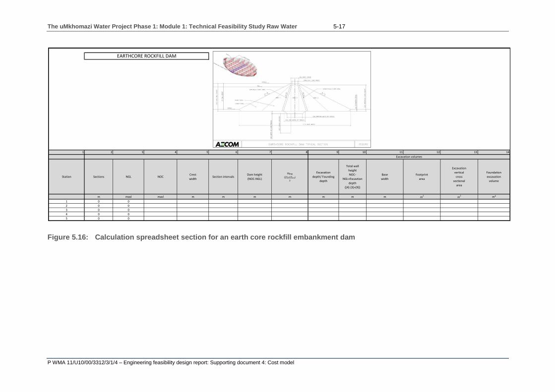
The uMkhomazi Water Project Phase 1: Module 1: Technical Feasibility Study Raw Water 5-17
P WMA 11/U10/00/3312/3/1/4 – Engineering feasibility design report: Supporting document 4: Cost model
Figure 5.16: Calculation spreadsheet section for an earth core rockfill embankment dam
1 2 3 4 5 6 7 8 9 10 11 12 13 14
Station Sections NGL NOCCrest
widthSection intervals
Dam height
(NOC-NGL)
Havg
([7]n+[7]n+1)
2
Excavation
depth/ Founding
depth
Total wall
height
NOC-
NGL+Excavtion
depth
([4]-[3]+[9])
Base
width
Footprint
area
Excavation
vertical
cross
sectional
area
Foundation
excavation
volume
m masl masl m m m m m m m m2 m2 m³
1 0 0
2 0 0
3 0 0
4 0 0
5 0 0
Excavation volumes
EARTHCORE ROCKFILL DAM

The uMkhomazi Water Project Phase 1: Module 1: Technical Feasibility Study Raw Water 5-18
P WMA 11/U10/00/3312/3/1/4 – Engineering feasibility design report: Supporting document 4: Cost model
A description of each column in the calculation spreadsheet (Figure 5.16) is provided
in Table 5.3 with the paragraph number relating to the column number:
Table 5.3: Earth core rockfill embankment dam calculation sheet
components
Earth core rockfill embankment dam
1 Station
The number of sections that may be input into the long section; each row in
the cost model dam volume calculation spreadsheet is referred to as a
station.
2 Section
The dam is divided into a number of sections at a specified section interval.
The finer the section interval the finer the solution, conversely the larger the
section interval, the coarser the solution. A maximum of 200 sections may be
entered.
3 NGL The natural ground level.
4 NOC The non-overspill crest that is determined by adding the FSL and freeboard
of the dam.
5 Crest width The width of the crest of the dam. Input as a variable in the variable input
table.
6 Section intervals The distance normal to two alongside sections.
7 Dam height The difference in height between the NOC and the NGL.
8 Havg
The average height between two alongside sections;
𝑯𝒂𝒗𝒈 =𝑺𝒏 + 𝑺𝒏+𝟏
𝟐
(3.3.1)
9 Excavation depth/
Founding depth
The depth from the NGL to the founding level, a constant value for all the
sections may be entered; else if a geotechnical investigation was
undertaken, a separate depth may be entered for each section in the long
section input table.
10 Total wall height Includes the height determined by subtracting the NGL from the NOC and
the addition of the excavation depth
11 Base width
The horizontal NGL length for each section determined by adding the
horizontal component of the upstream and downstream slope including the
crest width of the dam.
12 Footprint area
The horizontal natural ground level surface area calculated by using the base
width of two alongside sections and the section interval. The area is
calculated using the trapezoidal rule.
13 Excavation vertical
cross sectional area
The area of a section of the dam that represents the excavation (see
Figure 5.17).

The uMkhomazi Water Project Phase 1: Module 1: Technical Feasibility Study Raw Water 5-19
P WMA 11/U10/00/3312/3/1/4 – Engineering feasibility design report: Supporting document 4: Cost model
Figure 5.17: Excavation vertical cross sectional area
14
Foundation
excavation
volume
The volume of material that needs to be excavated in order to reach the
founding level. The volume is calculated by summing all the volumes
determined by using two alongside sections and the section interval.
𝑽𝒐𝒍𝒖𝒎𝒆 = ∑(𝑺𝒆𝒄𝒕𝒊𝒐𝒏𝒂𝒍 𝒂𝒓𝒆𝒂(𝑵 − 𝟏)
𝒏
𝑵=𝟏
+ 𝑺𝒆𝒄𝒕𝒊𝒐𝒏𝒂𝒍 𝒂𝒓𝒆𝒂(𝑵))(𝑺𝒆𝒄𝒕𝒊𝒐𝒏𝒂𝒍 𝒊𝒏𝒕𝒆𝒓𝒗𝒂𝒍(𝑵)
𝟐)
(3.3.2)
15 Total wall height Includes the height determined by subtracting the NGL from the NOC and
adding the excavation depth.
16 Crest width The width of the crest of the dam. Input as a variable in the variable inputs
table.
17 Area 1 Crest area
The rectangular area calculated by multiplying the total wall height by the crest
width;
𝑨𝒓𝒆𝒂 = [𝑻𝒐𝒕𝒂𝒍 𝒘𝒂𝒍𝒍 𝒉𝒆𝒊𝒈𝒉𝒕] × [𝑪𝒓𝒆𝒔𝒕 𝒘𝒊𝒅𝒕𝒉] (3.3.3)
18 Area 2 Upstream
The triangular area calculated by using the total wall height and the upstream
slope of the dam;
𝑨𝒓𝒆𝒂 = [𝑻𝒐𝒕𝒂𝒍 𝒘𝒂𝒍𝒍 𝒉𝒆𝒊𝒈𝒉𝒕]𝟐 ×[𝑼𝒑𝒔𝒕𝒓𝒆𝒂𝒎 𝒔𝒍𝒐𝒑𝒆]
𝟐 (3.3.4)
19 Area 3
Downstream
The triangular area calculated by using the total wall height and the
downstream slope of the dam;
𝑨𝒓𝒆𝒂 = [𝑻𝒐𝒕𝒂𝒍 𝒘𝒂𝒍𝒍 𝒉𝒆𝒊𝒈𝒉𝒕]𝟐 ×[𝑫𝒐𝒘𝒏𝒔𝒕𝒓𝒆𝒂𝒎 𝒔𝒍𝒐𝒑𝒆]
𝟐 (3.3.5)
20 Total cross
sectional area The sum of Area 1: Crest, Area 2: Upstream slope, Area 3: Downstream slope.

The uMkhomazi Water Project Phase 1: Module 1: Technical Feasibility Study Raw Water 5-20
P WMA 11/U10/00/3312/3/1/4 – Engineering feasibility design report: Supporting document 4: Cost model
21 Volume of the
embankment
The sum of all the sectional volumes calculated by using two alongside
sections and the sectional interval. The trapezoidal rule is used to calculate the
volume;
𝑽𝒐𝒍𝒖𝒎𝒆 = ∑(𝑺𝒆𝒄𝒕𝒊𝒐𝒏𝒂𝒍 𝒂𝒓𝒆𝒂(𝑵 − 𝟏)
𝒏
𝑵=𝟏
+ 𝑺𝒆𝒄𝒕𝒊𝒐𝒏𝒂𝒍 𝒂𝒓𝒆𝒂(𝑵))(𝑺𝒆𝒄𝒕𝒊𝒐𝒏𝒂𝒍 𝒊𝒏𝒕𝒆𝒓𝒗𝒂𝒍(𝑵)
𝟐)
(3.3.6)
22 Impervious core
height The height of the clay core.
23 Area 1: Upstream
The triangular area calculated using the clay core height and the upstream
slope of the clay core;
𝑨𝒓𝒆𝒂 = [𝑰𝒎𝒑𝒆𝒓𝒗𝒊𝒐𝒖𝒔 𝒄𝒐𝒓𝒆 𝒉𝒆𝒊𝒈𝒉𝒕]𝟐
×[𝑪𝒍𝒂𝒚 𝒄𝒐𝒓𝒆 𝒖𝒑𝒔𝒕𝒓𝒆𝒂𝒎 𝒔𝒍𝒐𝒑𝒆]
𝟐
(3.3.7)
24 Area 2
Downstream
The triangular area calculated using the clay core height and the downstream
slope of the clay core;
𝑨𝒓𝒆𝒂 = [𝑰𝒎𝒑𝒆𝒓𝒗𝒊𝒐𝒖𝒔 𝒄𝒐𝒓𝒆 𝒉𝒆𝒊𝒈𝒉𝒕]𝟐
×[𝑪𝒍𝒂𝒚 𝒄𝒐𝒓𝒆 𝒅𝒐𝒘𝒏𝒔𝒕𝒓𝒆𝒂𝒎 𝒔𝒍𝒐𝒑𝒆]
𝟐
(3.3.8)
25 Clay core crest
width The width of the clay core crest. Input as a variable in the variable inputs table.
26 Area 3 Crest core
area
The rectangular area calculated by using the clay core crest width and the
impervious core height.
27
Total area
impervious core
(vertical)
The sum of the Area 1: Upstream, Area 2: Downstream and Area 3: Crest core
area.
28 Impervious core
volume
The sum of the individual section volumes calculated by using two alongside
sections and the section interval;
𝑽𝒐𝒍𝒖𝒎𝒆
= ∑([𝟐𝟕]𝑻𝒐𝒕𝒂𝒍 𝒂𝒓𝒆𝒂 𝒊𝒏𝒑𝒆𝒓𝒗𝒊𝒐𝒖𝒔 𝒄𝒐𝒓𝒆(𝑵 − 𝟏)
𝑵
𝑵=𝟏
+ [𝟐𝟕]𝑻𝒐𝒕𝒂𝒍 𝒂𝒓𝒆𝒂 𝒊𝒏𝒑𝒆𝒓𝒗𝒊𝒐𝒖𝒔 𝒄𝒐𝒓𝒆(𝑵))(𝑺𝒆𝒄𝒕𝒊𝒐𝒏𝒂𝒍 𝒊𝒏𝒕𝒆𝒓𝒗𝒂𝒍(𝑵)
𝟐)
(3.3.9)
29 Upstream filter
area
The area of the upstream filter is calculated by multiplying the impervious core
height by the horizontal filter width;
𝑨𝒓𝒆𝒂 = [𝑭𝒊𝒍𝒕𝒆𝒓 𝒘𝒊𝒅𝒕𝒉] × [𝟐𝟐 𝑰𝒎𝒑𝒆𝒓𝒗𝒊𝒐𝒖𝒔 𝒄𝒐𝒓𝒆 𝒉𝒆𝒊𝒈𝒉𝒕] (3.3.10)

The uMkhomazi Water Project Phase 1: Module 1: Technical Feasibility Study Raw Water 5-21
P WMA 11/U10/00/3312/3/1/4 – Engineering feasibility design report: Supporting document 4: Cost model
30 Upstream filter
volume
The volume is determined by the sum of all the sectional volumes, which is
determined by using two alongside sections and the sectional interval. The
trapezoidal formula is used to calculate the volume;
𝑽𝒐𝒍𝒖𝒎𝒆
= ∑([𝟐𝟗]𝑼𝒑𝒔𝒕𝒓𝒆𝒂𝒎 𝒇𝒊𝒍𝒕𝒆𝒓 𝒂𝒓𝒆𝒂(𝑵 − 𝟏)
𝒏
𝑵=𝟏
+ [𝟐𝟗]𝑼𝒑𝒔𝒕𝒓𝒆𝒂𝒎 𝒇𝒊𝒍𝒕𝒆𝒓 𝒂𝒓𝒆𝒂(𝑵))(𝑺𝒆𝒄𝒕𝒊𝒐𝒏𝒂𝒍 𝒊𝒏𝒕𝒆𝒓𝒗𝒂𝒍(𝑵)
𝟐)
(3.3.11)
31 Downstream filter
area
The downstream filter area is located adjacent to the clay core and is
calculated by multiplying the clay core height by the downstream filter width;
𝑨𝒓𝒆𝒂 = [𝑭𝒊𝒍𝒕𝒆𝒓 𝒘𝒊𝒅𝒕𝒉][𝟐𝟐] (3.3.12)
32 Downstream filter
volume
The volume is determined by the sum of all the sectional volumes, which is
determined by using two alongside sections and the section interval. The
trapezoidal formula is used to calculate the volume;
𝑽𝒐𝒍𝒖𝒎𝒆
= ∑([𝟑𝟏]𝑫𝒐𝒘𝒏𝒔𝒕𝒓𝒆𝒂𝒎 𝒇𝒊𝒍𝒕𝒆𝒓 𝒂𝒓𝒆𝒂(𝑵 − 𝟏)
𝒏
𝑵=𝟏
+ [𝟑𝟏]𝑫𝒐𝒘𝒏𝒔𝒕𝒓𝒆𝒂𝒎 𝒇𝒊𝒍𝒕𝒆𝒓 𝒂𝒓𝒆𝒂(𝑵))(𝑺𝒆𝒄𝒕𝒊𝒐𝒏𝒂𝒍 𝒊𝒏𝒕𝒆𝒓𝒗𝒂𝒍(𝑵)
𝟐)
(3.3.13)
33 Depth of the core
trench
Depending on the available information, a single depth can be input for all the
sections or if a more detailed geotechnical investigation has been conducted,
individual depths for each section can be input in the long section input table.
34 Top width of
trench
The top width is calculated at the shell excavation depth and is determined
using the total wall height;
𝑻𝒐𝒑 𝒘𝒊𝒅𝒕𝒉 = 𝑻𝒐𝒕𝒂𝒍 𝒘𝒂𝒍𝒍 𝒉𝒆𝒊𝒈𝒉𝒕
𝟐 (3.3.14)
35 Bottom width of
the trench
The bottom width of the trench is calculated by subtracting the horizontal
component of the batter slopes from the top width of the trench. If this results in
a value less than zero, the bottom width is set to zero.
36 Trench section
area (vertical)
The vertical area is calculated for each section that represents the trench area.
The area is calculated using the trapezoidal rule;
𝑨𝒓𝒆𝒂 = ([𝟑𝟒]𝑻𝒐𝒑 𝒘𝒊𝒅𝒕𝒉 𝒐𝒇 𝒕𝒓𝒆𝒏𝒄𝒉
+ [𝟑𝟓]𝑩𝒐𝒕𝒕𝒐𝒎 𝒘𝒊𝒅𝒕𝒉 𝒐𝒇 𝒕𝒓𝒆𝒏𝒄𝒉)
× ([𝟑𝟑]𝑫𝒆𝒑𝒕𝒉 𝒐𝒇 𝒄𝒐𝒓𝒆 𝒕𝒓𝒆𝒏𝒄𝒉)
(3.3.15)

The uMkhomazi Water Project Phase 1: Module 1: Technical Feasibility Study Raw Water 5-22
P WMA 11/U10/00/3312/3/1/4 – Engineering feasibility design report: Supporting document 4: Cost model
37 Volume of trench
The volume of the trench is calculated by determining the sum of the volumes
of all the section intervals. The section interval volumes is calculated using two
alongside sections and the section interval;
𝑽𝒐𝒍𝒖𝒎𝒆
= ∑([𝟑𝟔]𝑻𝒓𝒆𝒏𝒄𝒉 𝒔𝒆𝒄𝒕𝒊𝒐𝒏 𝒂𝒓𝒆𝒂(𝑵 − 𝟏)
𝒏
𝑵=𝟏
+ [𝟑𝟔]𝑻𝒓𝒆𝒏𝒄𝒉 𝒔𝒆𝒄𝒕𝒊𝒐𝒏 𝒂𝒓𝒆𝒂(𝑵))(𝑺𝒆𝒄𝒕𝒊𝒐𝒏𝒂𝒍 𝒊𝒏𝒕𝒆𝒓𝒗𝒂𝒍(𝑵)
𝟐)
(3.3.16)
38 Footprint width
The width determined at the shell excavation line by calculating the sum of the
crest width and the horizontal components of the upstream and downstream
slopes.
39 Footprint area
The area of the footprint calculated at the shell excavation line. The area is
calculated using the trapezoidal rule using two alongside footprint widths and
the section interval. The sum is determined by adding all the individual section
interval areas;
𝑽𝒐𝒍𝒖𝒎𝒆
= ∑([𝟑𝟖]𝑭𝒐𝒐𝒕𝒑𝒓𝒊𝒏𝒕 𝒘𝒊𝒅𝒕𝒉(𝑵 − 𝟏)
𝒏
𝑵=𝟏
+ [𝟑𝟖]𝑭𝒐𝒐𝒕𝒑𝒓𝒊𝒏𝒕 𝒘𝒊𝒅𝒕𝒉(𝑵))(𝑺𝒆𝒄𝒕𝒊𝒐𝒏𝒂𝒍 𝒊𝒏𝒕𝒆𝒓𝒗𝒂𝒍(𝑵)
𝟐)
(3.3.17)
40 Curtain grout
The length of the curtain grout is calculated as percentage (Input in the
variable inputs table) of the height of the dam. The grout spacing is entered as
a variable in the variable inputs table. The total length of the grout is calculated
by averaging two alongside section grout depths and multiplying it by the
number of intervals calculated by dividing the section interval by the grout
spacing.
41 Blanket grout
A constant depth of the grout is input as a variable in the variable inputs table.
The length of the blanket grout or consolidation grouting is determined by
multiplying the grout length by the number of holes, which is determined by
dividing the section interval by the grout spacing.
42 Outer shell area
The sectional area that is determined by subtracting the upstream and
downstream filter volumes, clay core volume from the total sectional area (see
Figure 5.18).

The uMkhomazi Water Project Phase 1: Module 1: Technical Feasibility Study Raw Water 5-23
P WMA 11/U10/00/3312/3/1/4 – Engineering feasibility design report: Supporting document 4: Cost model
Figure 5.18: Outer shell area
4
2
Inner shell
(vertical area)
Upstream
The area calculated using the clay core height and the upstream inner shell
zone slope that is specified in variable inputs table (see Figure 5.19)
Figure 5.19: Inner shell (Vertical area) Upstream
4
4
Inner shell
(vertical area)
Downstream
The area calculated using the clay core height and the downstream inner
shell zone slope that is specified in the variable input table.
4
5
Total inner zone
area
The sum of the “Inner shell (vertical area) Upstream” and the “Inner shell
(vertical area) Downstream” inner shell zones.
4
6
Total outer zone
area
Is determined by subtracting the total inner zone area from the outer shell
area (see Figure 5.20).
43
44
45
46
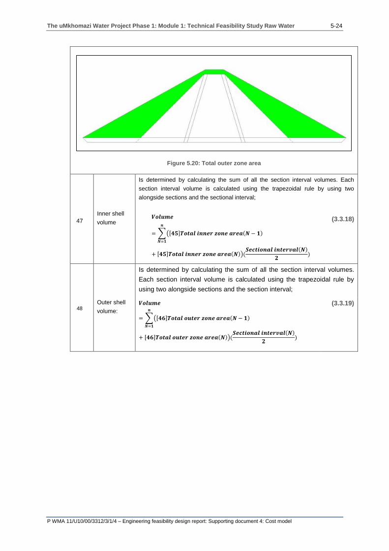
The uMkhomazi Water Project Phase 1: Module 1: Technical Feasibility Study Raw Water 5-24
P WMA 11/U10/00/3312/3/1/4 – Engineering feasibility design report: Supporting document 4: Cost model
Figure 5.20: Total outer zone area
4
7
Inner shell
volume
Is determined by calculating the sum of all the section interval volumes. Each
section interval volume is calculated using the trapezoidal rule by using two
alongside sections and the sectional interval;
𝑽𝒐𝒍𝒖𝒎𝒆
= ∑([𝟒𝟓]𝑻𝒐𝒕𝒂𝒍 𝒊𝒏𝒏𝒆𝒓 𝒛𝒐𝒏𝒆 𝒂𝒓𝒆𝒂(𝑵 − 𝟏)
𝒏
𝑵=𝟏
+ [𝟒𝟓]𝑻𝒐𝒕𝒂𝒍 𝒊𝒏𝒏𝒆𝒓 𝒛𝒐𝒏𝒆 𝒂𝒓𝒆𝒂(𝑵))(𝑺𝒆𝒄𝒕𝒊𝒐𝒏𝒂𝒍 𝒊𝒏𝒕𝒆𝒓𝒗𝒂𝒍(𝑵)
𝟐)
(3.3.18)
4
8
Outer shell
volume:
Is determined by calculating the sum of all the section interval volumes.
Each section interval volume is calculated using the trapezoidal rule by
using two alongside sections and the section interval;
𝑽𝒐𝒍𝒖𝒎𝒆
= ∑([𝟒𝟔]𝑻𝒐𝒕𝒂𝒍 𝒐𝒖𝒕𝒆𝒓 𝒛𝒐𝒏𝒆 𝒂𝒓𝒆𝒂(𝑵 − 𝟏)
𝒏
𝑵=𝟏
+ [𝟒𝟔]𝑻𝒐𝒕𝒂𝒍 𝒐𝒖𝒕𝒆𝒓 𝒛𝒐𝒏𝒆 𝒂𝒓𝒆𝒂(𝑵))(𝑺𝒆𝒄𝒕𝒊𝒐𝒏𝒂𝒍 𝒊𝒏𝒕𝒆𝒓𝒗𝒂𝒍(𝑵)
𝟐)
(3.3.19)
47
48
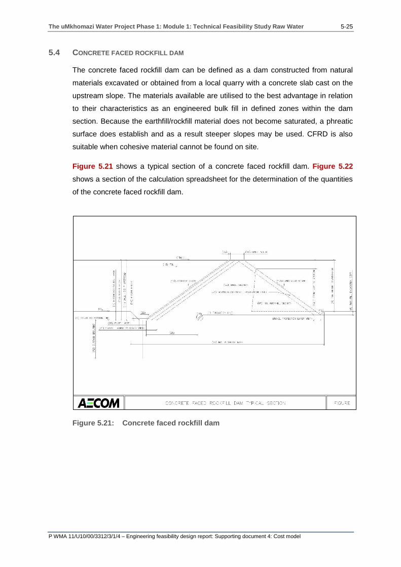
The uMkhomazi Water Project Phase 1: Module 1: Technical Feasibility Study Raw Water 5-25
P WMA 11/U10/00/3312/3/1/4 – Engineering feasibility design report: Supporting document 4: Cost model
5.4 CONCRETE FACED ROCKFILL DAM
The concrete faced rockfill dam can be defined as a dam constructed from natural
materials excavated or obtained from a local quarry with a concrete slab cast on the
upstream slope. The materials available are utilised to the best advantage in relation
to their characteristics as an engineered bulk fill in defined zones within the dam
section. Because the earthfill/rockfill material does not become saturated, a phreatic
surface does establish and as a result steeper slopes may be used. CFRD is also
suitable when cohesive material cannot be found on site.
Figure 5.21 shows a typical section of a concrete faced rockfill dam. Figure 5.22
shows a section of the calculation spreadsheet for the determination of the quantities
of the concrete faced rockfill dam.
Figure 5.21: Concrete faced rockfill dam
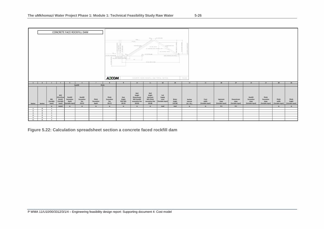
The uMkhomazi Water Project Phase 1: Module 1: Technical Feasibility Study Raw Water 5-26
P WMA 11/U10/00/3312/3/1/4 – Engineering feasibility design report: Supporting document 4: Cost model
Figure 5.22: Calculation spreadsheet section a concrete faced rockfill dam
1 2 3 4 5 6 7 8 9 10 11 12 13 14 15 16 17 18 19 20 21
Station Section
NGL
[Variable
Input]
NOC
[FSL]+[Free
board]
[Variable
Input]
Rockfill
Excavation
depth
[Variable input]
Rockfill
Excavation
line
[3]-[5]
Plinth
Excavation
depth
Plinth
Excavation
line
[3]-[7]
Dam
Height
NOC-NGL
[4]-[3]
Wall
Height
Downstream
NOC-Rockfill
excavation line
[4]-[6]
Wall
Height
Upstream
NOC-Plinth
excavation line
[4]-[8]
Full
Supply
Level
[Variable Input]
Water
height
[12]-[8]
Section
Interval
[1]i - [1]i-1
Crest
width
[Variable Input]
Upstream
slope
[Variable Input]
Downstream
slope
[Variable Input]
Rockfill
Excavation
slope
[Variable Input]
Plinth
Excavation
slope
[Variable Input]
Plinth
width
[Variable Input]
Plinth
height
[Variable input]
m mamsl m m m m m m m masl masl m m H:1 H:1 m m
1 0 0
2 0 0
3 0 0
4 0 0
5 0 0
6 0 0
CONCRETE FACE ROCKFILL DAM
PlinthRockfill

The uMkhomazi Water Project Phase 1: Module 1: Technical Feasibility Study Raw Water 5-27
P WMA 11/U10/00/3312/3/1/4 – Engineering feasibility design report: Supporting document 4: Cost model
A description of each column in the calculation spreadsheet (Figure 5.22) is provided
in Table 5.4 with the paragraph number relating to the column number:
Table 5.4: Concrete faced rockfill dam calculation sheet components
Concrete faced rockfill dam
1 Station
The number of sections that may be input into the long section; each row
in the cost model dam volume calculation spreadsheet is referred to as a
station.
2 Section
The dam is divided into a number of sections at a specified section
interval. The smaller the section interval the finer the solution conversely
the larger the section interval, the coarser the solution. A maximum of 200
sections may be entered.
3 NGL Natural ground level.
4 NOC Non-overspill crest. The NOC is calculated by adding the FSL to the
freeboard height.
5 Rockfill
excavation depth
The depth from the NGL to the founding level. Depending on the amount
of information available, either a constant depth can be input for all the
sections in the variable inputs table, else if a geotechnical survey has
being conducted, this information can be input.
6 Excavation line The height above sea level calculated by subtracting [5] Rockfill
excavation depth from the NGL.
7 Plinth excavation
depth
The depth at which the plinth will be founded on. The depth is given from
natural ground level.
8 Plinth excavation
line
The height above sea level at which the plinth is founded and is
determined by subtracting the [7] Plinth excavation depth from the natural
ground level.
9 Dam height The difference in height between the NOC and the NGL.
10 Wall height
downstream The difference in height between the NOC and the rockfill excavation line.
11 Wall height
upstream The difference in height between the NOC and the plinth excavation line.
12 Full supply level The maximum water level in the dam, which corresponds to the spillway
height.
13 Water height The difference in height between the FSL and the plinth excavation line.
14 Section interval The distance normal to two alongside sections.
15 Crest width The width of the crest that is input as a variable in the variable input table.
16 Upstream slope The horizontal component of the slope is an input in the variable input
table.
17 Downstream
slope
The horizontal component of the slope is an input in the variable input
table.
18 Rockfill
excavation slope
The batter slope at the downstream toe of the drain between the NGL and
the rockfill excavation line.
19 Plinth excavation
slope
The batter slope at the upstream toe of the dam between the NGL and the
plinth excavation line.
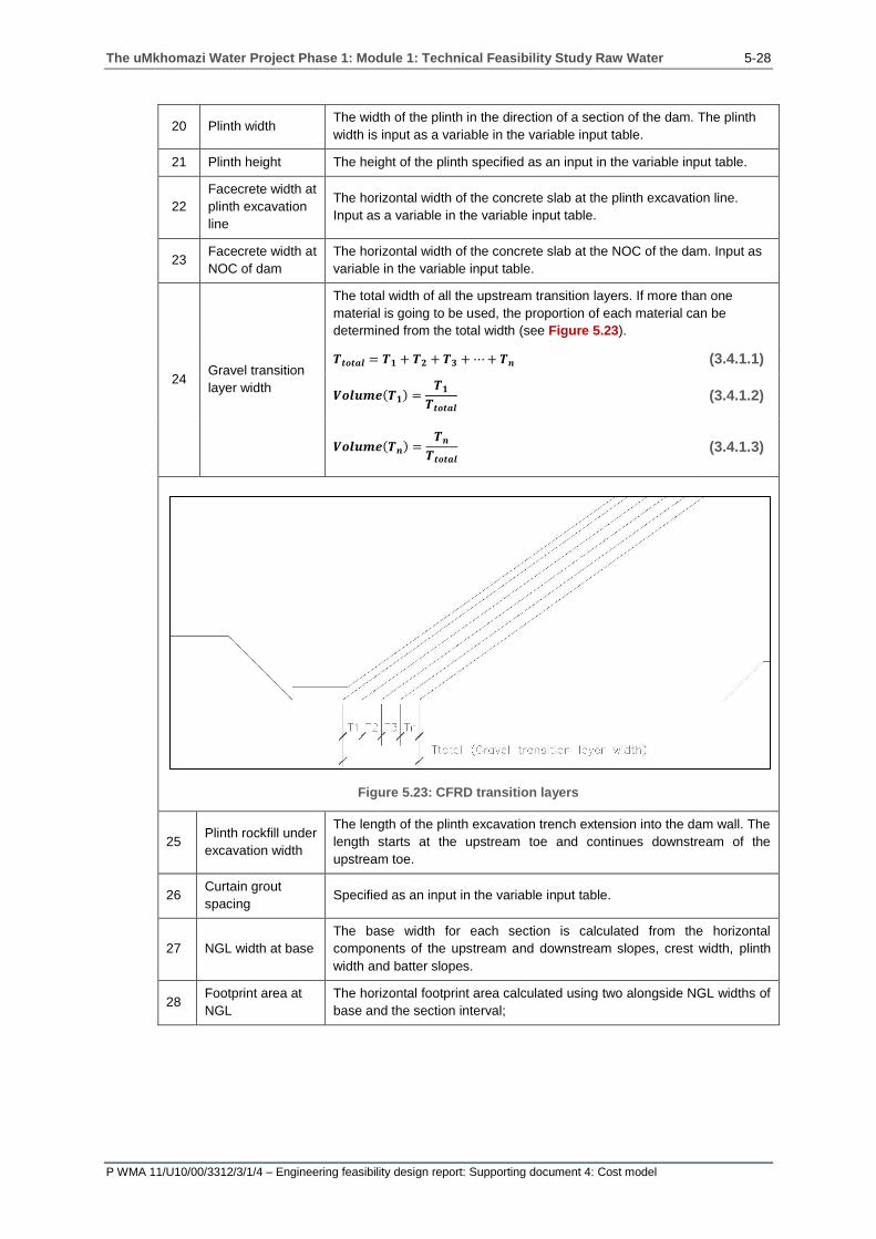
The uMkhomazi Water Project Phase 1: Module 1: Technical Feasibility Study Raw Water 5-28
P WMA 11/U10/00/3312/3/1/4 – Engineering feasibility design report: Supporting document 4: Cost model
20 Plinth width The width of the plinth in the direction of a section of the dam. The plinth
width is input as a variable in the variable input table.
21 Plinth height The height of the plinth specified as an input in the variable input table.
22
Facecrete width at
plinth excavation
line
The horizontal width of the concrete slab at the plinth excavation line.
Input as a variable in the variable input table.
23 Facecrete width at
NOC of dam
The horizontal width of the concrete slab at the NOC of the dam. Input as
variable in the variable input table.
24 Gravel transition
layer width
The total width of all the upstream transition layers. If more than one
material is going to be used, the proportion of each material can be
determined from the total width (see Figure 5.23).
𝑻𝒕𝒐𝒕𝒂𝒍 = 𝑻𝟏 + 𝑻𝟐 + 𝑻𝟑 + ⋯ + 𝑻𝒏 (3.4.1.1)
𝑽𝒐𝒍𝒖𝒎𝒆(𝑻𝟏) =𝑻𝟏
𝑻𝒕𝒐𝒕𝒂𝒍 (3.4.1.2)
𝑽𝒐𝒍𝒖𝒎𝒆(𝑻𝒏) =𝑻𝒏
𝑻𝒕𝒐𝒕𝒂𝒍 (3.4.1.3)
Figure 5.23: CFRD transition layers
25 Plinth rockfill under
excavation width
The length of the plinth excavation trench extension into the dam wall. The
length starts at the upstream toe and continues downstream of the
upstream toe.
26 Curtain grout
spacing Specified as an input in the variable input table.
27 NGL width at base
The base width for each section is calculated from the horizontal
components of the upstream and downstream slopes, crest width, plinth
width and batter slopes.
28 Footprint area at
NGL
The horizontal footprint area calculated using two alongside NGL widths of
base and the section interval;

The uMkhomazi Water Project Phase 1: Module 1: Technical Feasibility Study Raw Water 5-29
P WMA 11/U10/00/3312/3/1/4 – Engineering feasibility design report: Supporting document 4: Cost model
𝑨𝒓𝒆𝒂 = ∑([𝑵𝑮𝑳 𝒘𝒊𝒅𝒕𝒉 𝒐𝒇 𝒃𝒂𝒔𝒆(𝑵)
𝒏
𝑵=𝟏
+ 𝑵𝑮𝑳 𝒘𝒊𝒅𝒕𝒉 𝒐𝒇 𝒃𝒂𝒔𝒆 (𝑵
− 𝟏))([𝑺𝒆𝒄𝒕𝒊𝒐𝒏 𝒊𝒏𝒕𝒆𝒓𝒗𝒂𝒍]
𝟐)
(3.4.2)
29 Footprint
excavation area
The vertical area between the NGL and the rockfill excavation line. The
trapezoidal rule is used to calculate the area.
30 Footprint
excavation volume
The sum of all the section interval volumes that needs to be excavated in
order to reach the rockfill excavation line. The trapezoidal rule is used to
calculate the volume;
𝑽𝒐𝒍𝒖𝒎𝒆 = ∑([(𝟐𝟗)𝑭𝒐𝒐𝒕𝒑𝒓𝒊𝒏𝒕 𝒆𝒙𝒄𝒂𝒗𝒂𝒕𝒊𝒐𝒏 𝒂𝒓𝒆𝒂(𝑵)
𝒏
𝑵=𝟏
+ (𝟐𝟗)𝑭𝒐𝒐𝒕𝒑𝒓𝒊𝒏𝒕 𝒆𝒙𝒄𝒂𝒗𝒂𝒕𝒊𝒐𝒏 𝒂𝒓𝒆𝒂(𝑵
− 𝟏))([𝑺𝒆𝒄𝒕𝒊𝒐𝒏 𝒊𝒏𝒕𝒆𝒓𝒗𝒂𝒍]
𝟐)
(3.4.3)
31 Plinth excavation
area
The vertical area between the rockfill excavation line and the plinth
excavation line that needs to be excavated (see Figure 5.24).
Figure 5.24: Plinth excavation area
32 Plinth excavation
volume
The volume of material that needs to be excavated between the
rockfill excavation line and the plinth excavation line. The sum of the
total volume is determined by calculating each individual section
volume using the trapezoidal rule;
𝑽𝒐𝒍𝒖𝒎𝒆 = ∑(𝑷𝒍𝒊𝒏𝒕𝒉 𝒆𝒙𝒄𝒂𝒗𝒂𝒕𝒊𝒐𝒏 𝒂𝒓𝒆𝒂(𝑵)
𝒏
𝑵=𝟏
+ 𝑷𝒍𝒊𝒏𝒕𝒉 𝒆𝒙𝒄𝒂𝒗𝒂𝒕𝒊𝒐𝒏 𝒂𝒓𝒆𝒂(𝑵
− 𝟏))([𝑺𝒆𝒄𝒕𝒊𝒐𝒏 𝒊𝒏𝒕𝒆𝒓𝒗𝒂𝒍]
𝟐)
(3.4.4)
33 Plinth excavation area
from NGL
The vertical sectional area corresponding to the area between the
NGL and the plinth excavation line (see Figure 5.25).

The uMkhomazi Water Project Phase 1: Module 1: Technical Feasibility Study Raw Water 5-30
P WMA 11/U10/00/3312/3/1/4 – Engineering feasibility design report: Supporting document 4: Cost model
Figure 5.25: Plinth excavation area from NGL
34 Plinth excavation
volume from NGL
The sum of the volume of all the sectional interval volumes
calculated using the trapezoidal rule. Each sectional interval volume
is calculated using two alongside sections and the section interval;
𝑽𝒐𝒍𝒖𝒎𝒆
= ∑(𝑷𝒍𝒊𝒏𝒕𝒉 𝒆𝒙𝒄𝒂𝒗𝒂𝒕𝒊𝒐𝒏 𝒂𝒓𝒆𝒂 𝒇𝒓𝒐𝒎 𝑵𝑮𝑳(𝑵)
𝒏
𝑵=𝟏
+ 𝑷𝒍𝒊𝒏𝒕𝒉 𝒆𝒙𝒄𝒂𝒗𝒂𝒕𝒊𝒐𝒏 𝒂𝒓𝒆𝒂 𝒇𝒓𝒐𝒎 𝑵𝑮𝑳(𝑵
− 𝟏))([𝑺𝒆𝒄𝒕𝒊𝒐𝒏 𝒊𝒏𝒕𝒆𝒓𝒗𝒂𝒍]
𝟐)
(3.4.5)
35 Gravel transition layer
section area
The vertical section area of the gravel transition layer that is equal to
the horizontal gravel transition width multiplied by the upstream wall
height.
36 Gravel transition layer
section volume
The sum of all the section interval volumes. The section interval
volumes are calculated using the trapezoidal rule;
𝑽𝒐𝒍𝒖𝒎𝒆
= ∑(𝑮𝒓𝒂𝒗𝒆𝒍 𝒕𝒓𝒂𝒏𝒔𝒊𝒕𝒊𝒐𝒏 𝒍𝒂𝒚𝒆𝒓 𝒔𝒆𝒄𝒕𝒊𝒐𝒏 𝒂𝒓𝒆𝒂(𝑵)
𝒏
𝑵=𝟏
+ 𝑮𝒓𝒂𝒗𝒆𝒍 𝒕𝒓𝒂𝒏𝒔𝒊𝒕𝒊𝒐𝒏 𝒍𝒂𝒚𝒆𝒓 𝒔𝒆𝒄𝒕𝒊𝒐𝒏 𝒂𝒓𝒆𝒂 (𝑵
− 𝟏))([𝑺𝒆𝒄𝒕𝒊𝒐𝒏 𝒊𝒏𝒕𝒆𝒓𝒗𝒂𝒍]
𝟐)
(3.4.6)
37 Curtain grouting section
length
The depth of the curtain grouting is specified as a percentage of the
height of the dam wall;
𝑳𝒆𝒏𝒈𝒕𝒉 = [𝟏𝟏] × [𝑹𝒂𝒕𝒊𝒐] (3.4.7)
38 Total grout length
Curtain grouting spacing can be less than the section interval. The
total length of the grout holes is calculated by averaging the height
between the two alongside sections and multiplying it by the number
of grout holes that need to be bored.
𝑳𝒆𝒏𝒈𝒕𝒉
= ∑([𝑺𝒆𝒄𝒕𝒊𝒐𝒏 𝒊𝒏𝒕𝒆𝒓𝒗𝒂𝒍]
[𝑪𝒖𝒓𝒕𝒂𝒊𝒏 𝒈𝒓𝒐𝒖𝒕 𝒔𝒑𝒂𝒄𝒊𝒏𝒈])
𝒏
𝑵=𝟏
×(𝑪𝒖𝒓𝒕𝒂𝒊𝒏 𝒈𝒓𝒐𝒖𝒕𝒊𝒏𝒈 𝒔𝒆𝒄𝒕𝒊𝒐𝒏 𝒍𝒆𝒏𝒈𝒕𝒉(𝑵) + (𝑪𝒖𝒓𝒕𝒂𝒊𝒏 𝒈𝒓𝒐𝒖𝒕𝒊𝒏𝒈 𝒔𝒆𝒄𝒕𝒊𝒐𝒏 𝒍𝒆𝒏𝒈𝒕𝒉(𝑵 − 𝟏))
𝟐
(3.4.8)

The uMkhomazi Water Project Phase 1: Module 1: Technical Feasibility Study Raw Water 5-31
P WMA 11/U10/00/3312/3/1/4 – Engineering feasibility design report: Supporting document 4: Cost model
39 Foundation preparation
section width
The sum of the upstream and downstream horizontal slope
components, the crest width, the plinth width and the length of the
batter slopes between the rockfill excavation line and the plinth
excavation line.
40 Foundation preparation
horizontal area
The foundation surface area calculated as the combined surface
between the rockfill excavation line and the plinth excavation line.
Does not consider the upstream and downstream batter slopes. The
area is calculated using the trapezoidal rule by using two alongside
foundation preparation section widths and the section interval;
𝑽𝒐𝒍𝒖𝒎𝒆
= ∑(𝑭𝒐𝒖𝒏𝒅𝒂𝒕𝒊𝒐𝒏 𝒑𝒓𝒆𝒑𝒂𝒓𝒂𝒕𝒊𝒐𝒏 𝒔𝒆𝒄𝒕𝒊𝒐𝒏 𝒘𝒊𝒅𝒕𝒉(𝑵)
𝒏
𝑵=𝟏
+ 𝑭𝒐𝒖𝒏𝒅𝒂𝒕𝒊𝒐𝒏 𝒑𝒓𝒆𝒑𝒂𝒓𝒂𝒕𝒊𝒐𝒏 𝒔𝒆𝒄𝒕𝒊𝒐𝒏 𝒘𝒊𝒅𝒕𝒉(𝑵
− 𝟏))([𝑺𝒆𝒄𝒕𝒊𝒐𝒏 𝒊𝒏𝒕𝒆𝒓𝒗𝒂𝒍]
𝟐)
(3.4.9)
41
Plinth foundation
preparation horizontal
area
The foundation surface area calculated using the plinth width and the
section interval;
𝑽𝒐𝒍𝒖𝒎𝒆 = ∑(𝑷𝒍𝒊𝒏𝒕𝒉 𝒘𝒊𝒅𝒕𝒉(𝑵)
𝒏
𝑵=𝟏
+ 𝑷𝒍𝒊𝒏𝒕𝒉 𝒘𝒊𝒅𝒕𝒉(𝑵
− 𝟏))([𝑺𝒆𝒄𝒕𝒊𝒐𝒏 𝒊𝒏𝒕𝒆𝒓𝒗𝒂𝒍]
𝟐)
(3.4.10)
42 Facecrete section area
The section area representing the facecrete. It is calculated by
averaging the width at the NOC level and plinth level and multiplying
it by the height of the dam;
𝑽𝒐𝒍𝒖𝒎𝒆 = ∑(𝐅𝐚𝐜𝐞𝐜𝐫𝐞𝐭𝐞 𝐬𝐞𝐜𝐭𝐢𝐨𝐧 𝐚𝐫𝐞𝐚(𝑵)
𝒏
𝑵=𝟏
+ 𝐅𝐚𝐜𝐞𝐜𝐫𝐞𝐭𝐞 𝐬𝐞𝐜𝐭𝐢𝐨𝐧 𝐚𝐫𝐞𝐚(𝑵
− 𝟏))([𝑺𝒆𝒄𝒕𝒊𝒐𝒏 𝒊𝒏𝒕𝒆𝒓𝒗𝒂𝒍]
𝟐)
(3.4.11)
43 Total dam section area The total sectional area that includes all the material (see
Figure 5.26).
Figure 5.26: Total dam section area

The uMkhomazi Water Project Phase 1: Module 1: Technical Feasibility Study Raw Water 5-32
P WMA 11/U10/00/3312/3/1/4 – Engineering feasibility design report: Supporting document 4: Cost model
44 Total dam volume
The sum of all the sectional interval volumes that are calculated
using two alongside total dam section areas and the section interval;
𝑽𝒐𝒍𝒖𝒎𝒆 = ∑(𝐓𝐨𝐭𝐚𝐥 𝐝𝐚𝐦 𝐬𝐞𝐜𝐭𝐢𝐨𝐧 𝐚𝐫𝐞𝐚(𝑵)
𝒏
𝑵=𝟏
+ 𝐓𝐨𝐭𝐚𝐥 𝐝𝐚𝐦𝐬𝐞𝐜𝐭𝐢𝐨𝐧 𝐚𝐫𝐞𝐚(𝑵
− 𝟏))([𝑺𝒆𝒄𝒕𝒊𝒐𝒏 𝒊𝒏𝒕𝒆𝒓𝒗𝒂𝒍]
𝟐)
(3.4.12)
45 Rockfill section area
The sectional area representing the area of rockfill. It is calculated by
subtracting the line upstream gravel transition layer area [35] from
the total dam section area [44];
𝑨𝒓𝒆𝒂
= [𝑻𝒐𝒕𝒂𝒍 𝒅𝒂𝒎 𝒔𝒆𝒄𝒕𝒊𝒐𝒏 𝒂𝒓𝒆𝒂]𝑵
− [𝑮𝒓𝒂𝒗𝒆𝒍 𝒕𝒓𝒂𝒏𝒔𝒊𝒕𝒊𝒐𝒏 𝒍𝒂𝒚𝒆𝒓 𝒔𝒆𝒄𝒕𝒊𝒐𝒏 𝒂𝒓𝒆𝒂]𝑵 (3.4.13)
46 Total rockfill volume
The sum of the rockfill sectional interval volume that is calculated
using two alongside rockfill section areas and the section interval;
𝑽𝒐𝒍𝒖𝒎𝒆 = ∑(𝐑𝐨𝐜𝐤𝐟𝐢𝐥𝐥 𝐬𝐞𝐜𝐭𝐢𝐨𝐧 𝐚𝐫𝐞𝐚(𝑵)
𝒏
𝑵=𝟏
+ 𝐑𝐨𝐜𝐤𝐟𝐢𝐥𝐥 𝐬𝐞𝐜𝐭𝐢𝐨𝐧 𝐚𝐫𝐞𝐚(𝑵
− 𝟏))([𝑺𝒆𝒄𝒕𝒊𝒐𝒏 𝒊𝒏𝒕𝒆𝒓𝒗𝒂𝒍]
𝟐)
(3.4.14)
47 The toe section height
If a different material is specified for the toe section of the dam then
the height of the toe section is equal to the difference in height
between the downstream wall height [10] subtracted the variable
input specified for the height from the NOC level to the top of the toe
section.
48 Toe rockfill section area The sectional area of the rockfill material (see Figure 5.27).
Figure 5.27: Toe rockfill section area
49 Toe rockfill volume:
The sum of the sectional interval volumes, which is calculated by
using two alongside toe rockfill section areas and the section interval;
𝑽𝒐𝒍𝒖𝒎𝒆 = ∑(𝐓𝐨𝐞 𝐫𝐨𝐜𝐤𝐟𝐢𝐥𝐥 𝐬𝐞𝐜𝐭𝐢𝐨𝐧 𝐚𝐫𝐞𝐚(𝑵)
𝒏
𝑵=𝟏
+ 𝐓𝐨𝐞 𝐫𝐨𝐜𝐤𝐟𝐢𝐥𝐥 𝐬𝐞𝐜𝐭𝐢𝐨𝐧 𝐚𝐫𝐞𝐚(𝑵
− 𝟏))([𝑺𝒆𝒄𝒕𝒊𝒐𝒏 𝒊𝒏𝒕𝒆𝒓𝒗𝒂𝒍]
𝟐)
(3.4.15)

The uMkhomazi Water Project Phase 1: Module 1: Technical Feasibility Study Raw Water 5-33
P WMA 11/U10/00/3312/3/1/4 – Engineering feasibility design report: Supporting document 4: Cost model
50
Downstream gravel
protection layer section
area:
If a downstream gravel protection layer is used in the dam, the area
is equal to the specified input width multiplied by the height of the
dam.
51 Downstream gravel
protection layer volume
The sum of the sectional interval volume, which is calculated using
two alongside downstream gravel protection layer section areas and
the section interval (see Figure 5.28);
𝑽𝒐𝒍𝒖𝒎𝒆
= ∑(𝐃𝐨𝐰𝐧𝐬𝐭𝐫𝐞𝐚𝐦 𝐠𝐫𝐚𝐯𝐞𝐥 𝐩𝐫𝐨𝐭𝐞𝐜𝐭𝐢𝐨𝐧 𝐥𝐚𝐭𝐞𝐫 𝐬𝐞𝐜𝐭𝐢𝐨𝐧 𝐚𝐫𝐞𝐚(𝒊)
𝒏
𝑵=𝟏
+ 𝐃𝐨𝐰𝐧𝐬𝐭𝐫𝐞𝐚𝐦 𝐠𝐫𝐚𝐯𝐞𝐥 𝐩𝐫𝐨𝐭𝐞𝐜𝐭𝐢𝐨𝐧 𝐥𝐚𝐭𝐞𝐫 𝐬𝐞𝐜𝐭𝐢𝐨𝐧 𝐚𝐫𝐞𝐚(𝑵
− 𝟏))([𝑺𝒆𝒄𝒕𝒊𝒐𝒏 𝒊𝒏𝒕𝒆𝒓𝒗𝒂𝒍]
𝟐)
(3.4.16)
Figure 5.28: Downstream gravel protection layer volume
If both a gravel protection layer and a toe section material are used then the toe height will start at the
transition from the rockfill material to the gravel protection layer.
52 Total shell rockfill
volume
The volume of rockfill material required excluding the downstream
protection layer volume and the toe section volume (see
Figure 5.29).
Figure 5.29: Total shell rockfill volume
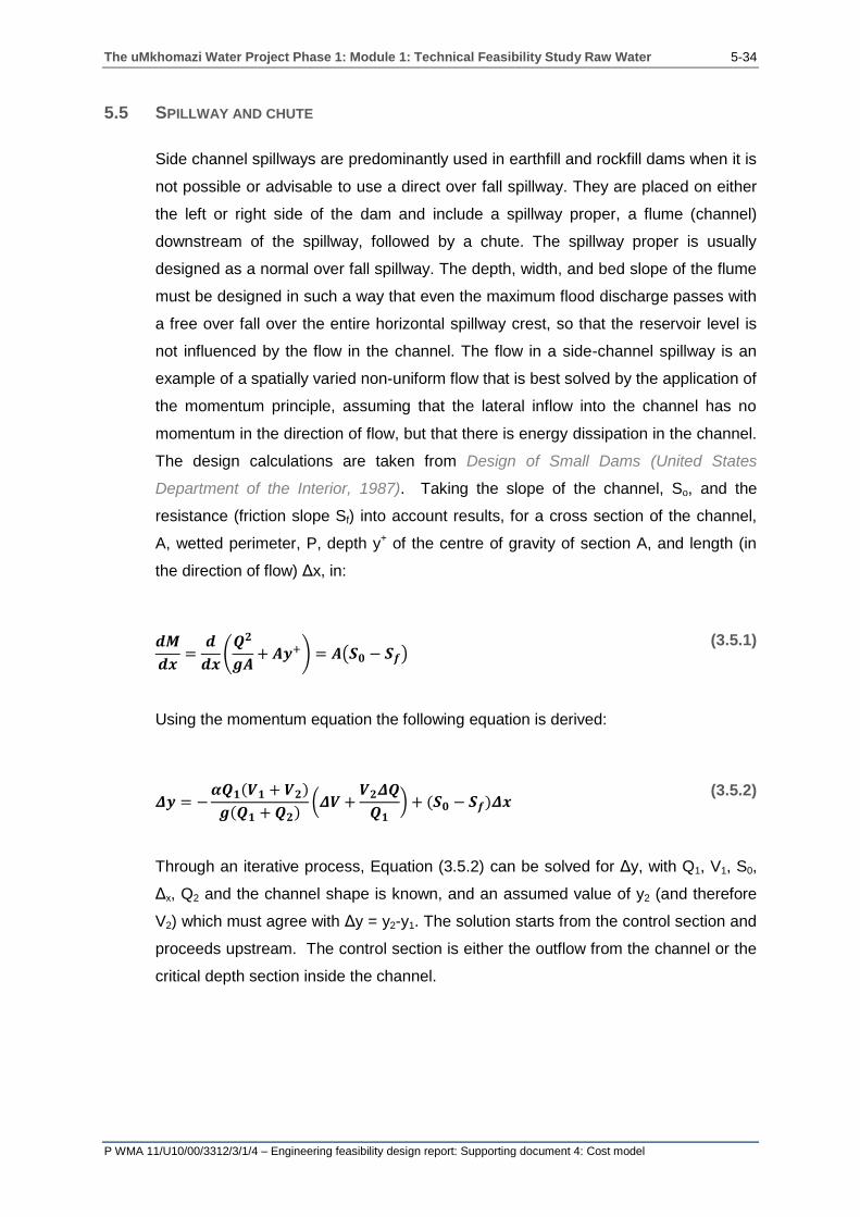
The uMkhomazi Water Project Phase 1: Module 1: Technical Feasibility Study Raw Water 5-34
P WMA 11/U10/00/3312/3/1/4 – Engineering feasibility design report: Supporting document 4: Cost model
5.5 SPILLWAY AND CHUTE
Side channel spillways are predominantly used in earthfill and rockfill dams when it is
not possible or advisable to use a direct over fall spillway. They are placed on either
the left or right side of the dam and include a spillway proper, a flume (channel)
downstream of the spillway, followed by a chute. The spillway proper is usually
designed as a normal over fall spillway. The depth, width, and bed slope of the flume
must be designed in such a way that even the maximum flood discharge passes with
a free over fall over the entire horizontal spillway crest, so that the reservoir level is
not influenced by the flow in the channel. The flow in a side-channel spillway is an
example of a spatially varied non-uniform flow that is best solved by the application of
the momentum principle, assuming that the lateral inflow into the channel has no
momentum in the direction of flow, but that there is energy dissipation in the channel.
The design calculations are taken from Design of Small Dams (United States
Department of the Interior, 1987). Taking the slope of the channel, So, and the
resistance (friction slope Sf) into account results, for a cross section of the channel,
A, wetted perimeter, P, depth y+ of the centre of gravity of section A, and length (in
the direction of flow) Δx, in:
𝒅𝑴
𝒅𝒙=
𝒅
𝒅𝒙(
𝑸𝟐
𝒈𝑨+ 𝑨𝒚+) = 𝑨(𝑺𝟎 − 𝑺𝒇)
(3.5.1)
Using the momentum equation the following equation is derived:
𝜟𝒚 = −𝜶𝑸𝟏(𝑽𝟏 + 𝑽𝟐)
𝒈(𝑸𝟏 + 𝑸𝟐)(𝜟𝑽 +
𝑽𝟐𝜟𝑸
𝑸𝟏) + (𝑺𝟎 − 𝑺𝒇)𝜟𝒙
(3.5.2)
Through an iterative process, Equation (3.5.2) can be solved for Δy, with Q1, V1, S0,
Δx, Q2 and the channel shape is known, and an assumed value of y2 (and therefore
V2) which must agree with Δy = y2-y1. The solution starts from the control section and
proceeds upstream. The control section is either the outflow from the channel or the
critical depth section inside the channel.

The uMkhomazi Water Project Phase 1: Module 1: Technical Feasibility Study Raw Water 5-35
P WMA 11/U10/00/3312/3/1/4 – Engineering feasibility design report: Supporting document 4: Cost model
Table 5.5: Ogee design calculations
Ogee design calculations
1.1 P/Ho = 1
1.2 Co = 2.14 (variable input) Coefficient form Q=CLH1.5
1.3 Qdesign = safety evaluation flood = Qsef
1.4 Spillway length (input)
1.5 Short side A Spillway section parallel to the chute (see Figure 5.30).
1.6 Long side B Spillway section perpendicular to the chute inlet (see Figure 5.30).
Figure 5.30: Spillway
1.7 QA The flow of water over the short side A
1.8 QB The flow of water over the long side B.
1.9 Qb/m The flow of water of the long side per unit length of B.
1.10 The water height above the ogee section (see Figure 5.31)
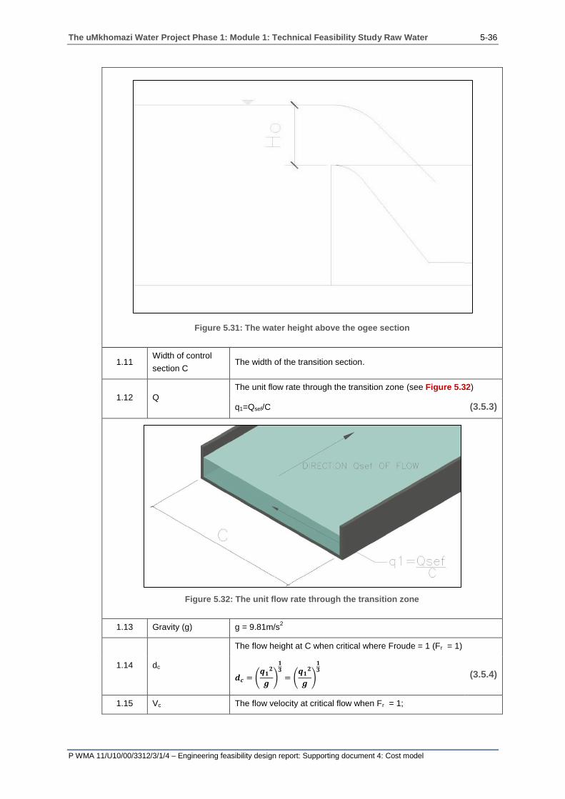
The uMkhomazi Water Project Phase 1: Module 1: Technical Feasibility Study Raw Water 5-36
P WMA 11/U10/00/3312/3/1/4 – Engineering feasibility design report: Supporting document 4: Cost model
Figure 5.31: The water height above the ogee section
1.11 Width of control
section C The width of the transition section.
1.12 Q
The unit flow rate through the transition zone (see Figure 5.32)
q1=Qsef/C (3.5.3)
Figure 5.32: The unit flow rate through the transition zone
1.13 Gravity (g) g = 9.81m/s2
1.14 dc
The flow height at C when critical where Froude = 1 (Fr = 1)
𝒅𝒄 = (𝒒𝟏
𝟐
𝒈)
𝟏𝟑
= (𝒒𝟏
𝟐
𝒈)
𝟏𝟑
(3.5.4)
1.15 Vc The flow velocity at critical flow when Fr = 1;

The uMkhomazi Water Project Phase 1: Module 1: Technical Feasibility Study Raw Water 5-37
P WMA 11/U10/00/3312/3/1/4 – Engineering feasibility design report: Supporting document 4: Cost model
1.16 hvc
The velocity component of the energy head;
𝒉𝒗𝒄 =𝑽𝒄
𝟐
𝟐 ∗ 𝒈 (3.5.5)
1.17 Section width at A = short section A: (=1.11)
1.18 Transition loss 𝟎. 𝟐(𝒉𝒗𝒄 − 𝒉𝒗𝟎)
1.19 Side slope or ogee slope (N), (see Figure 5.33)
Figure 5.33: Side slope or ogee slope

The uMkhomazi Water Project Phase 1: Module 1: Technical Feasibility Study Raw Water 5-38
P WMA 11/U10/00/3312/3/1/4 – Engineering feasibility design report: Supporting document 4: Cost model
1.20 Bottom slope Spillway section slope
1.21 d2
The depth the water will flow through at the start of the transition
zone;
d2 > dc (subcritical flow)
1.22 A2 The area the water flows through at the start of the transition zone.
1.23 V2 The velocity the water flows through at the transition zone.
1.24 hv2
The velocity component of the energy head;
𝒉𝒗𝟐 =𝑽𝟐
𝟐
𝟐 ∗ 𝒈 (3.5.6)
1.25 Transition length
(D) The transition zone between the spillway section and the chute.
1.26 Left = Right 𝒅𝟐 + 𝒉𝒉𝒗𝟐𝟎 = 𝒅𝒄 + 𝒉𝒗𝒄 + 𝟎. 𝟐(𝒉𝒗𝒄 − 𝒉𝒗𝟎) (3.5.7)
1.27.1 Station
Section along the long side B at which calculations are done. Zero is
at the short side A and at the chute, the station is equal to the long
side B.
Figure 5.34: Spillway design

The uMkhomazi Water Project Phase 1: Module 1: Technical Feasibility Study Raw Water 5-39
P WMA 11/U10/00/3312/3/1/4 – Engineering feasibility design report: Supporting document 4: Cost model
1.27.2 Δx Change in x = the distance between the sections.
1.27.3 The elevation
bottom The height above sea level at each section.
1.27.4 Trial Δy The column is an input in the variable input table. Each input is
iterated until (1.27.4) = (1.27.19).
1.27.5 Water surface
elevation Iterative
1.27.6 dn The static height of the water above the water surface elevation for
each section.
1.27.7 Width The base width that is equal to the short side A.
1.27.8 Section area The cross sectional area of water at each section.
1.27.9 Q The flow at each section.
1.27.10 Velocity The velocity of water at each section.
1.27.11 Qn + Qn-1 The sum of the flow of section n + section n-1.
1.27.12 𝑸𝒏
𝒈 ∗ (𝑸𝒏 + 𝑸𝒏+𝟏)
1.27.13 𝑽𝒏 + 𝑽𝒏−𝟏
1.27.14 𝑽𝒏 + 𝑽𝒏−𝟏
1.27.15 𝑸𝒏 − 𝑸𝒏−𝟏
1.27.16 (𝑸𝒏 − 𝑸𝒏−𝟏)
𝑸𝒏
1.27.17 𝑽𝒏−𝟏 ×(𝑸𝒏 − 𝑸𝒏−𝟏)
𝑸𝒏
1.27.18 𝑽𝒏 + 𝑽𝒏−𝟏 + 𝑽𝒏−𝟏 ×(𝑸𝒏 − 𝑸𝒏−𝟏)
𝑸𝒏
1.27.19 𝑸𝒏
𝒈 ∗ (𝑸𝒏 + 𝑸𝒏−𝟏)× (𝑽𝒏 + 𝑽𝒏−𝟏) × (𝑽𝒏 − 𝑽𝒏−𝟏) × 𝑽𝒏−𝟏 ×
(𝑸𝒏 − 𝑸𝒏−𝟏)
𝑸𝒏
1.28 Crest level It can be seen that the crest level is equal to the full supply level of
the dam.
1.29 Reservoir water
level The full supply level plus the flood surcharge (Ho).
1.30 Submergence <
2/3 Ho: The spillway can only be allowed to submerge 2/3 of the Ho.
1.31 Equals to the FSL plus the 2/3 Ho.
1.32 The highest water level above the crest in the spillway section.

The uMkhomazi Water Project Phase 1: Module 1: Technical Feasibility Study Raw Water 5-40
P WMA 11/U10/00/3312/3/1/4 – Engineering feasibility design report: Supporting document 4: Cost model
Table 5.6: Chute design calculations
Chute design calculations
2.1 Width The width of the chute.
2.2 Qdes The design flood in the chute (=Qsef).
2.3 q1 The flow per unit width of the chute.
2.4 g Gravity acceleration.
2.5 The depth of the water at the start of the chute.
2.6 Vc Critical flow velocity.
2.7 hvc =Vc
2
2 ∗ g The velocity component of the energy head.
2.8.1 Qd The design flood through the chute.
2.8.2 N Manning’s n-value (roughness value) Concrete = 0.015.
2.8.3 Width Width of the chute.
2.8.4 Elevation The elevation of the chute above mean sea level.
2.8.5 Δz The change in elevation between two points.
2.8.6 Stretch Distance between two sections.
2.8.7 Dn The height of the water above the chute elevation.
2.8.8 Area The cross sectional of the chute.
2.8.9 Perimeter The wetted perimeter of the chute at each section.
2.8.10 R Hydraulic radius.
2.8.11 V The flow velocity at each section.
2.8.12 Hv1 𝒉𝒗𝒏 =𝑽𝒏
𝟐
𝟐∗𝒈 The velocity component of the energy head.
2.8.13 Slope The slope of the chute at each section.
2.8.14 Average slope
The average slope between two sections;
𝑺𝒏 + 𝑺𝒏−𝟏
𝟐= 𝑺𝒂𝒗𝒆𝒓𝒂𝒈𝒆 (3.5.8)
2.8.15 Δhl Energy loss between two sections
2.8.16 Bernoulli equation
The Bernoulli equation is used to determine energy heads at each
of the sections.
If the left is equal to the right then it’s in equilibrium;
[Left = right] therefore equilibrium.
2.8.17 Froude number
Determine whether the flow is subcritical or supercritical
Fr < 1: Subcritical
Fr > 1: Supercritical
2.9 The weighted average of the water height alone the length of the chute.

The uMkhomazi Water Project Phase 1: Module 1: Technical Feasibility Study Raw Water 5-41
P WMA 11/U10/00/3312/3/1/4 – Engineering feasibility design report: Supporting document 4: Cost model
Table 5.7: Ogee and chute volumes
Ogee and chute volumes
3.1 Crest level Equal to the full supply level.
3.2 Top spillway floor The level of the spillway floor at the start of the spillway section at
the short side A.
3.3 Bottom spillway floor The level of the end of the spillway section at the beginning of the
transition zone.
3.4 Hstart The difference in height between the crest level and the start of the
spillway section.
3.5 Hend The difference in height between the FSL and the end of the
spillway section.
3.6 Haverage The weighted average height between Hstart and Hend.
3.7 x & y
The top width of the spillway section derived from:
𝒙𝟐 = 𝟐 × 𝑯 × 𝒚
Where:
(3.5.9)
Ho = the water head above the crest level at the Qdesign/Qsef;
3.8 Area 1 Equal to H/4 × Havg.
3.9 Area 2 𝒙 × (𝑯𝒂𝒗𝒈 − 𝒚)
3.10 Area 3
The area representing the ogee spillway;
𝑨𝒓𝒆𝒂 = 𝒙 × 𝒚 −𝟏
𝟔×
𝒙𝟑
𝑯𝒐 (3.5.10)
3.11 Area 4 The cross sectional area representing the downstream slope.
3.12 Base
The width of the base of the ogee;
𝑩𝒂𝒔𝒆 =𝑯𝒐
𝟒+ 𝒙 + (𝑯𝒂𝒗𝒈 − 𝑯𝒐) × 𝑺𝒐𝒈𝒆𝒆 (3.5.11)
3.13 Area total The sum of Area 1, Area 2, Area 3 and Area 4.
3.14 Volume The volume of concrete in the ogee section. Is equal to the
average area multiplied by the length of the ogee.
3.15 Reinforcing The total amount of steel is calculated by multiplying the volume of
concrete by a proportion of the steel per unit concrete.
3.16 Vertical shuttering The vertical shuttering on the upstream face of the ogee spillway.
3.17 Slope shuttering The shuttering on the sloped section on the downstream face of
the ogee spillway.
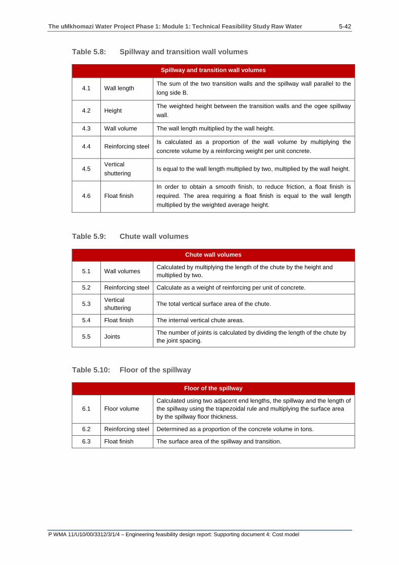
The uMkhomazi Water Project Phase 1: Module 1: Technical Feasibility Study Raw Water 5-42
P WMA 11/U10/00/3312/3/1/4 – Engineering feasibility design report: Supporting document 4: Cost model
Table 5.8: Spillway and transition wall volumes
Spillway and transition wall volumes
4.1 Wall length The sum of the two transition walls and the spillway wall parallel to the
long side B.
4.2 Height The weighted height between the transition walls and the ogee spillway
wall.
4.3 Wall volume The wall length multiplied by the wall height.
4.4 Reinforcing steel Is calculated as a proportion of the wall volume by multiplying the
concrete volume by a reinforcing weight per unit concrete.
4.5 Vertical
shuttering Is equal to the wall length multiplied by two, multiplied by the wall height.
4.6 Float finish
In order to obtain a smooth finish, to reduce friction, a float finish is
required. The area requiring a float finish is equal to the wall length
multiplied by the weighted average height.
Table 5.9: Chute wall volumes
Chute wall volumes
5.1 Wall volumes Calculated by multiplying the length of the chute by the height and
multiplied by two.
5.2 Reinforcing steel Calculate as a weight of reinforcing per unit of concrete.
5.3 Vertical
shuttering The total vertical surface area of the chute.
5.4 Float finish The internal vertical chute areas.
5.5 Joints The number of joints is calculated by dividing the length of the chute by
the joint spacing.
Table 5.10: Floor of the spillway
Floor of the spillway
6.1 Floor volume
Calculated using two adjacent end lengths, the spillway and the length of
the spillway using the trapezoidal rule and multiplying the surface area
by the spillway floor thickness.
6.2 Reinforcing steel Determined as a proportion of the concrete volume in tons.
6.3 Float finish The surface area of the spillway and transition.

The uMkhomazi Water Project Phase 1: Module 1: Technical Feasibility Study Raw Water 5-43
P WMA 11/U10/00/3312/3/1/4 – Engineering feasibility design report: Supporting document 4: Cost model
Table 5.11: Floor of the chute
Floor of the chute
7.1 Floor concrete
volume The volume of concrete for the base of the chute.
7.2 Reinforcing steel The amount of reinforcement calculated as a proportion of the concrete
volume.
7.3 Float finish The inclined base surface area of the chute.
7.4 Core drain
The drains placed beneath the chute. It is calculated by taking the chute
length and dividing it by the drainage spacing and multiplying it by the
chute width.
7.5 Filter sand The sand required for the core drain filters.
7.6 Anchors
The anchors are placed on a grid n x n beneath the chute. The spacing
and length of the anchors is input as a variable in the variable input
table.
7.7 Core drain
excavation
Equal to the total volume that needs to be excavated for the coredrain.
The total length of the core drain multiplied by
(0.6 x 0.6).
Table 5.12: Excavation for spillway and chute
Excavation for spillway and chute
8.1 – 8.10 Input parameters or previously calculated parameters.
8.11 Spillway excavation
volume
The volume of material that needs to be excavated for the
spillway.
8.12 Transition excavation
volume
The volume of material that needs to be excavated for the
transition section.
8.13 Chute excavation
volume
The volume of material that needs to be excavated for the
chute.

The uMkhomazi Water Project Phase 1: Module 1: Technical Feasibility Study Raw Water 6-1
P WMA 11/U10/00/3312/3/1/4 – Engineering feasibility design report: Supporting document 4: Cost model
6 REFERENCES
Department of Water Affairs and Forestry.1996. Vaal Augmentation Planning Study: Guidelines for the preliminary sizing, costing and engineering economic evaluation of planning options. BKS: PC000/00/14394
Novak P, Moffat A.I.B, Nalluri C et al. 2007. Hydraulic Structure. Fourth edition. Taylor & Francis. New York
U.S. Army Corps of Engineers. 2000. Engineering and Design: Roller Compacted Concrete. Manual No. 1110-2-2006
United States Department of the Interior. 1987. Design of Small Dams. Bureau of Reclamation: US Printing Office. United States of America

The uMkhomazi Water Project Phase 1: Module 1: Technical Feasibility Study Raw Water
P WMA 11/U10/00/3312/3/1/4 – Engineering feasibility design report: Supporting document 4: Cost model
Appendix A
Final cost model used for the
uMkhomazi Water Project (CD) (Note: Excel spreadsheet is protected. Password: J0176)


![Untitled-1 [] · 2018-03-26 · Water Quality Monitoring System Series 1 month continuous monitoring ... quality of sea water, river water, dams, well water, ground water, c.ty ...](https://static.fdocuments.us/doc/165x107/5f757172a8aa4701d2322aa1/untitled-1-2018-03-26-water-quality-monitoring-system-series-1-month-continuous.jpg)


![Water Waste Water Treatment & Re-use Norit 1 & 2[1]](https://static.fdocuments.us/doc/165x107/55cf880055034664618c578f/water-waste-water-treatment-re-use-norit-1-21.jpg)

