The Ultratec TDD Detector · Contents 1 About TTYs and the TDD Detector 1 About TTYs and the Deaf...
24
The Ultratec TDD Detector Installation Instructions Ultratec, Inc. 450 Science Drive Madison, WI 53711 BOOKTD31
Transcript of The Ultratec TDD Detector · Contents 1 About TTYs and the TDD Detector 1 About TTYs and the Deaf...

The Ultratec TDD DetectorInstallation Instructions
Ultratec, Inc.450 Science DriveMadison, WI 53711
BOOKTD31
NOTICE
All efforts have been made to insure the accuracy of the contents of this manual. However,Ultratec, Inc., can assume no responsibility for any errors in this manual or theirconsequences. This manual is furnished “as is,” without warranty of any kind, express orimplied, respecting its contents, including but not limited to implied warranties of the manual’squality, performance, merchantability or fitness for any particular purpose. Neither Ultratec,Inc., nor its dealers or distributors shall be liable to the purchaser or any other person or entitywith respect to any liability, loss, or damage caused or alleged to be caused directly orindirectly by this manual. The contents of this manual are subject to change without notice.
Second PrintingFebruary, 1998
© 1990, 1998 Ultratec, Inc.

Contents1 About TTYs and the TDD Detector
1 About TTYs and the Deaf TTY Network1 The Ultratec TDD Detector announces incoming TTY calls2 Control from a Touch-Tone® telephone keypad2 Manual and automatic reset—two ways to install the TDD
Detector
3 Install the TDD Detector
3 Description of manual and automatic reset installations—equipment
4 Manual reset installation instructions5 Automatic reset installation instructions
Off-hook detect installationLoop-current detect installation
9 Test Your Installation and Train Your Operators
9 Test procedures for manual and automatic reset installations10 Train your operators
13 TDD Detector Options, Service, and Specifications
13 TDD Detector options available13 If your TDD Detector needs repair15 TDD Detector Specifications
Appendix A: Rack InstallationFCC Information
The Ultratec TDD DetectorInstallation Instructions
NOTE: In this manual TTY, TDD and text telephone all refer to the same device.

The deaf telecommunications network began inthe early 1960's. Surplus Teletype machinesbecame available, and a deaf physicist namedRobert Weitbrecht invented a modem thatenabled these machines to communicate overthe telephone lines. These machines coupledwith the Weitbrecht modem became the firstTelecommunications Devices for the Deaf(TDDs). These Teletype machines used 5-levelBaudot code, and established the foundation fortoday's extensive deaf Baudot TTY network.
TTYs today are small electronic typewriter-likedevices that use built-in Weitbrecht-typemodems to communicate in Baudot code. Theyare used by people who are deaf or hearing orspeech impaired to access the telephonenetwork.
Please note: In this manual TTY, TDD and texttelephone all refer to the same device.
1
About TTYsand the TDD Detector
About TTYs andthe Deaf TTYNetwork
The Ultratec TDD Detector connects directlyto the telephone line. It monitors the line,listening for the sounds of incoming TTY(Baudot code) signals. Incoming TTY signalsmean that someone is typing to you on aTTY (text telephone).
When the TDD Detector hears TTY signalson the phone line, it responds in two ways.First, a built-in voice "announces" theincoming TTY call to you by repeating, "TDDCALL… TDD CALL." Second, the TDDDetector sends a TTY message for your callerto read on his or her TTY display. Thestandard TTY message says, "911 HEREPLEASE HOLD."
The Ultratec TDDDetectorannounces incoming TTYcalls

Although it is connected to your phone line, theTDD Detector does not affect the normaloperation of your telephone equipment.
NOTE: If your installation requires a TTYmessage that differs from the standard message("911 HERE PLEASE HOLD"), you can order acustom message for your TDD Detector. Seepage 11.
2
Your operators control the TDD Detector bypressing the "RESET" or "SEND" buttons on thefront panel. These same operations can beaccomplished by easy-to-use commands fromthe operator's Touch-Tone® telephone.Additional Touch-Tone® commands allow youroperators to abort (stop) the send command,and to test the TDD Detector's internal circuits.
Control from aTouch-Tonetelephone keypad
There are two ways to install the TDD Detectorin your setting—the manual reset installationand the automatic reset installation.
The manual reset installation requires nospecial wiring, but your operators should betrained to reset the Detector after it hasreceived a TTY call. The automatic resetinstallation requires that your TDD Detector beinstalled so that it can detect the on- and off-hook status of the phone line. It willautomatically reset when the operator hangs upafter a TTY call.
Refer to page 3 for a complete description of thetwo installations.
Manual andautomatic reset—two ways toinstall the TDDDetector
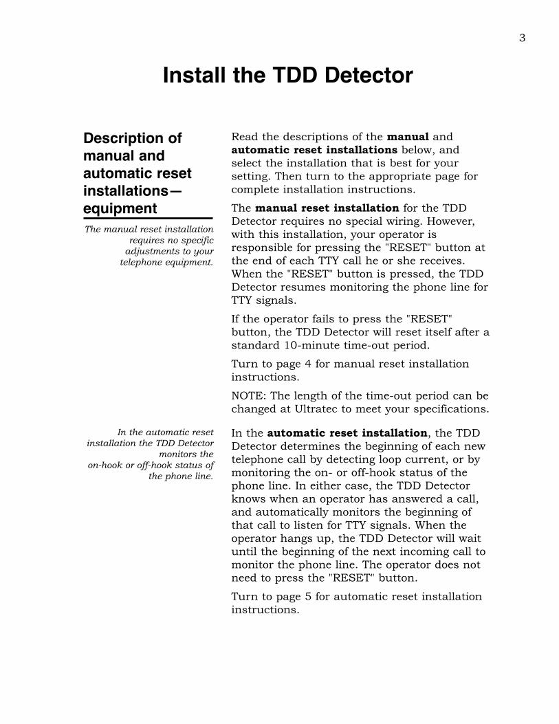
Read the descriptions of the manual andautomatic reset installations below, andselect the installation that is best for yoursetting. Then turn to the appropriate page forcomplete installation instructions.
The manual reset installation for the TDDDetector requires no special wiring. However,with this installation, your operator isresponsible for pressing the "RESET" button atthe end of each TTY call he or she receives.When the "RESET" button is pressed, the TDDDetector resumes monitoring the phone line forTTY signals.
If the operator fails to press the "RESET"button, the TDD Detector will reset itself after astandard 10-minute time-out period.
Turn to page 4 for manual reset installationinstructions.
NOTE: The length of the time-out period can bechanged at Ultratec to meet your specifications.
3
Install the TDD Detector
Description ofmanual andautomatic resetinstallations—equipmentThe manual reset installation
requires no specificadjustments to your
telephone equipment.
In the automatic reset installation, the TDDDetector determines the beginning of each newtelephone call by detecting loop current, or bymonitoring the on- or off-hook status of thephone line. In either case, the TDD Detectorknows when an operator has answered a call,and automatically monitors the beginning ofthat call to listen for TTY signals. When theoperator hangs up, the TDD Detector will waituntil the beginning of the next incoming call tomonitor the phone line. The operator does notneed to press the "RESET" button.
Turn to page 5 for automatic reset installationinstructions.
In the automatic resetinstallation the TDD Detector
monitors the on-hook or off-hook status of
the phone line.

The Ultratec TDD Detector uses two built-inRJ12C telephone modular jacks to connectdirectly to the telephone and the telephone line.These jacks are located on the back panel of theTDD Detector, and are labeled "LINE" and"TELEPHONE."
1. Install the TDD Detector in a place that isconvenient for your operator.
You can place the operator's telephone on top ofthe TDD Detector. The operator should be ableto reach the buttons on the front panel easily.
2. Connect the TDD Detector to the phoneline.
Use the modular telephone wire included withyour TDD Detector.
If you have a single phone line…
Plug one end of the modular phone wire intothe jack labeled "LINE" on the back panel ofyour TDD Detector. Plug the other end of thephone wire into the telephone line outlet.
If your setting has either a multi-line(KTS) telephone system, or a call-directorconsole…
Connect the TIP and RING for the telephone orfrom the call-director console to a telephonewire with a modular plug that fits a RJ12Cmodular jack. Plug the phone wire into the jacklabeled "LINE" on the back panel of your TDDDetector.
3. Connect the operator's telephone to theTDD Detector.
Plug the modular phone wire from theoperator's telephone into the "TELEPHONE"jack on the back panel of the TDD Detector.
4
Manual resetinstallationinstructions

5
4. Connect the AC adapter.
Plug the AC adapter wire into the "POWER" jackon the back panel of your TDD Detector.
Plug the AC adapter into an electrical outlet.
5. Press the "RESET" button to initialize theTDD Detector.
6. Connect an external speaker (optional).
Plug the speaker wire into the RCA phono jacklabeled "SPEAKER" on the back panel of yourTDD Detector.
7. Go on to page 9 to test your installation.
There are two ways to install your TDD Detectorso that it will automatically reset after each callyou receive—off-hook detect and loop-currentdetect installations. Either installation makes itpossible for the TDD Detector to know when thetelephone is on or off the hook.
Automatic resetinstallationinstructions
Off-hook detectinstallation
1. Install the TDD Detector in a place that isconvenient for your operator.
You can place the operator's telephone on top ofthe TDD Detector. The operator should be ableto reach the buttons on the front panel easily.
2. Connect the TDD Detector to the phoneline.
If you have a single phone line…
Plug one end of the modular phone wire intothe jack labeled "LINE" on the back panel ofyour TDD Detector. Plug the other end of thephone wire into the telephone line outlet.
If you have either a multi-line (KTS)telephone system, or a call-directorconsole…
Connect the TIP and RING for the telephone orfrom the call-director console to a telephonewire with a modular plug that fits a RJ12Cmodular jack. Plug the phone wire into the jacklabeled "LINE" on the back panel of your TDDDetector.

3. Connect the operator's telephone to theTDD Detector.
Plug the phone wire from the operator'stelephone into the "TELEPHONE" jack on theback panel of the TDD Detector.
4. Connect an unused pair of off-hookswitch contacts from the operator'stelephone to the 3.5mm "OFF-HOOK" jackon the back panel of your TDD Detector.
The switch contacts (N.O. contacts) should beclosed when the operator is off-hook (on theline).
5. Connect the AC adapter.
Plug the AC adapter wire into the "POWER" jackon the back panel of your TDD Detector.
Plug the AC adapter into an electrical outlet.
6. Press the "RESET" button to initialize theTDD Detector.
7. Connect an external speaker (optional).
Plug the speaker wire into the RCA phono jacklabeled "SPEAKER" on the back panel of yourTDD Detector.
8. Go on to page 9 to test your installation.
6

To set up your TDD Detector for AutomaticLoop Current Detection you must open the caseby removing the four screws in the bottom ofthe case. Move Jumper J3 as follows:
This enables the circuitry to detect loopcurrent. Whenever the operator goes off-hook,the TDD Detector will detect this loop currentand begin looking for a TTY call. Whenconnecting the operator's phone (Telephone)and the telephone line (Line), be sure not toreverse these connections on the back of theTDD Detector.
1. Install the TDD Detector in a place that isconvenient for your operator.
You can place the operator's telephone on top ofthe TDD Detector. The operator should be ableto reach the buttons on the front panel easily.
2. Connect the TDD Detector to the phoneline.
Use the modular telephone wire included withyour TDD Detector.
If you have a single phone line…
Plug one end of the modular phone wire into
7
Loop-current detectinstallation
J3
TDD Detector card showing Jumper J3
location.
From: To:
Move the jumper from the bottom two pins to the top two.

the jack labeled "LINE" on the back panel ofyour TDD Detector. Plug the other end of thephone wire into the telephone line outlet.
If you have either a multi-line (KTS)telephone system, or a call-directorconsole…
Connect the TIP and RING for the KTStelephone set or the TIP and RING from thecall-director console to a telephone wire. Thetelephone wire must have a modular plug thatfits a RJ12C modular jack. Plug the phone wireinto the jack labeled "LINE" on the back panelof your TDD Detector.
3. Connect the operator's telephone to theTDD Detector.
Plug the phone wire from the TIP and RING ofthe operator's telephone into the "TELEPHONE"jack on the back panel of the TDD Detector. TheTDD Detector will use the telephone line loopcurrent to monitor the on-hook and off-hookstatus of the operator's line.
4. Connect the AC adapter.
Plug the AC adapter wire into the "POWER" jackon the back panel of your TDD Detector.
Plug the AC adapter into an electrical outlet.
5. Press the "RESET" button to initialize theTDD Detector.
6. Connect an external speaker (optional).
Plug the speaker wire into the RCA phono jacklabeled "SPEAKER" on the back panel of yourTDD Detector.
7. Go on to page 9 to test your installation.
8

9
1. Check your phone line.
Pick up the receiver of a telephone connected toa line that the TDD Detector is monitoring.
Listen to the dial tone on the line. It shouldsound clear and loud.
2. Press the black "RESET" button on thefront panel.
3. Press the red "SEND" button.
You will hear a series of beeping sounds on thephone line. The beeping sounds you hear arethe sounds of the TTY message (in Baudot code)being sent over the line by the TDD Detector.The message says, "TYPE YOUR NAME GA."
Test your installation and train your operators
Test proceduresfor manual andautomatic resetinstallations
Touch-Tone commands canbe used by operators duringa call as well as for testing
the installation.
4. Test the Touch-Tone commands.
• Lift the receiver on the operator'stelephone.
• "SEND"—Type [#][#][1] on the telephonekeypad. This should initiate the "SEND"function. You should hear the sound ofTTY signals on the line as the message,"TYPE YOUR NAME GA" is sent.
• "TEST"—Type [#][#][2] on the telephonekeypad. This is the "TEST" command. Youshould hear a voice over the speakersaying "TDD CALL… TDD CALL…" Thevoice should sound clear and loud. Thenyou should hear the "beeping" sounds ofthe TTY message, "911 HERE PLEASEHOLD." All the lights on the front panel ofthe TDD Detector should come on, andthe receive circuitry in the unit isautomatically checked internally.

10
5. If you are using an external speaker tobroadcast the voice, type the [#][#][2]TEST command, and adjust the "VOLUME"control as the voice message is broadcast.
The "VOLUME" control is on the back panel ofthe TDD Detector. The voice should soundclear, and be loud enough to be heard easily.
6. Arrange for someone to call you with aTTY to test your installation.
Tell the person who calls you to type on the TTYkeyboard to send TTY signals after you answer.The TTY call should initiate the voice message("TDD CALL… TDD CALL…") and the TTYmessage ("911 HERE PLEASE HOLD") from theTDD Detector.
Train youroperators
1. Read the operator's instructions that wereincluded in this packet.
Make sure to read the instructions that apply tothe installation procedure you have chosen foryour location– automatic reset or manualreset installation.
Thorough training of youroperators in established
procedures for handling TTYcalls will help to assure
prompt response to peoplecalling by TTY.
2. Carefully review the operator'sinstructions with your operators.
You might want to make copies of theinstructions for your operators. Make sure youroperators know how to recognize a "silent" call,and what to do when they receive one. (Seepage 2 of the Operator's Instructions.) Makesure you have clearly established proceduresfor how to handle TTY calls once they have beenreceived and identified.
3. Help your operators to become sensitiveto the needs of the deaf or hard ofhearing people who may be calling you.
The responsibility of using special TTYequipment to respond to people who are deaf orhard of hearing may be new to some of youroperators. Inviting a spokesperson from the
deaf community in your area to speak with youroperators can help them to become sensitive toand aware of the special communicationproblems faced by people who cannot hear.
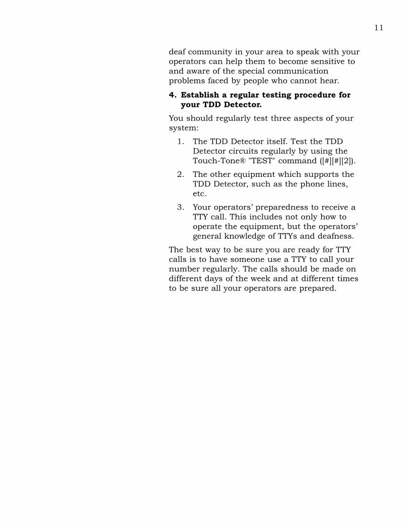
4. Establish a regular testing procedure foryour TDD Detector.
You should regularly test three aspects of yoursystem:
1. The TDD Detector itself. Test the TDDDetector circuits regularly by using theTouch-Tone® "TEST" command ([#][#][2]).
2. The other equipment which supports theTDD Detector, such as the phone lines,etc.
3. Your operators’ preparedness to receive aTTY call. This includes not only how tooperate the equipment, but the operators’general knowledge of TTYs and deafness.
The best way to be sure you are ready for TTYcalls is to have someone use a TTY to call yournumber regularly. The calls should be made ondifferent days of the week and at different timesto be sure all your operators are prepared.
11

12

13
• Rack installation. You can order yourTDD Detectors for installation in yourtelephone equipment rack. Order onecard in the rack for each line you want tomonitor.
TDD Detector options, service, and specifications
TDD Detectoroptions available
You can request any or all ofthe following options for your
TDD Detector.
• Custom outgoing TTY message. Ultrateccan program your TDD Detector to send aTTY message that you create.
• Custom voice message. The standardmessage, "TDD CALL… TDD CALL…" canbe reprogrammed to your specifications.
• Custom time delay. When the TDDDetector is installed in a manual resetsituation, it waits 10 minutes betweenTTY calls and then resets itself. You canspecify a different time delay.
If your TDDDetector needsrepair
If you think your TDD Detector needsrepair or service…
• Disconnect the TDD Detector from thephone line.
• Call the Ultratec National Service Center:
(608) 238-5400 (Voice/TTY)Toll Free: (800) 482-2424 (Voice/TTY)
Ask for the Customer ServiceDepartment.
• Tell them that you are a 911 center andthat you require immediate assistance.

Ultratec offers 24-hour replacementservice for your TDD Detector…
• If your TDD Detector needs repair orservice, Ultratec can send a replacementor "loaner" unit to you within 24 hours.
To send your TDD Detector in for repairor service…
• Package it in its original shipping box.
• Include a note that describes the problemyou are having. The note will help ourtechnicians complete your repair quickly.
• Insure your TDD Detector when you shipit. Ultratec is not responsible for anydamage that occurs to your unit duringshipping.
• Send your TDD Detector to the UltratecNational Service Center:
Ultratec National Service Center5901 Research Park Blvd.Madison, WI 53711
(608) 238-5400 (Voice/TTY)
Toll Free:(800) 482-2424 (Voice/TTY)
If the detector is under warranty, Ultratecwill pay for the cost of repair.
A technical manual for the TDD Detector isavailable from Ultratec.
14

TESTING PROCEDURES:
All TDD Detectors go through extensive testingprocedures as part of Ultratec's quality controlprogram. These procedures include completecomputerized testing of the board set, and a 24-hour hot/cold cycling of the unit whileoperating. These tests, along with Ultratec'sstandard quality assurance procedures (see theQuality Assurance Manual), help to ensure thatthe TDD Detector will meet the performancecriteria required of this kind of device.
PHYSICAL DIMENSIONS:
Size 1.40" high x 6.33" wide x 9.50"deep
Weight 1.25 pounds
POWER:
Requirements 12 VDC (Nominal), 3 W
TELECOMMUNICATIONS:
Codes: Detects Baudot (45.45 baud)
Sensitivity: -45 dBm (minimum)
Baudot and Bell 103 Output:-9 dBm (maximum)
Voice output: -25 dBm
FCC Part 68 approved:
FCC#: D8K7IB-19552-MD-N
REN: 0.5A
The TDD Detector is designed for indoor useonly.
15
TDD Detectorspecifications
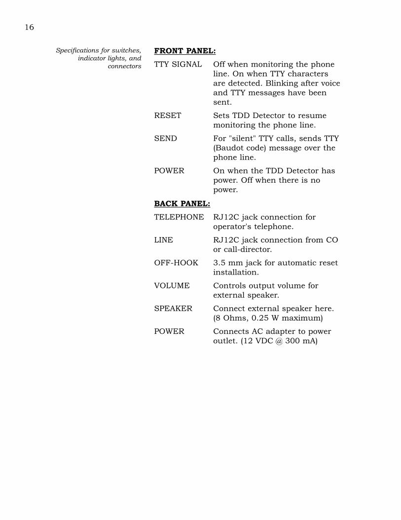
FRONT PANEL:
TTY SIGNAL Off when monitoring the phoneline. On when TTY charactersare detected. Blinking after voiceand TTY messages have beensent.
RESET Sets TDD Detector to resumemonitoring the phone line.
SEND For "silent" TTY calls, sends TTY(Baudot code) message over thephone line.
POWER On when the TDD Detector haspower. Off when there is nopower.
BACK PANEL:
TELEPHONE RJ12C jack connection foroperator's telephone.
LINE RJ12C jack connection from COor call-director.
OFF-HOOK 3.5 mm jack for automatic resetinstallation.
VOLUME Controls output volume forexternal speaker.
SPEAKER Connect external speaker here.(8 Ohms, 0.25 W maximum)
POWER Connects AC adapter to poweroutlet. (12 VDC @ 300 mA)
16
Specifications for switches,indicator lights, and
connectors

Appendix ATDD Detector Rack Installation
Equipment Needed:
Screwdriver
Two 50-pin, male, micro-ribbon connectors
Procedure:
1. Install the Ultratec TDD Detector Rack Enclosure in the TelephoneCommunications Rack where desired. Position the 12VDC 10 Amppower supply in the rack or close enough to it so that the 9-ft. powercable can reach the TDD Detector Rack enclosure. Do not connectthe power cable to the TDD Detector rack or plug the power supplyinto the 115-VAC power outlet.
2. Remove all the cards from the TDD Detector Rack Enclosure byunscrewing the 2 wing bolts, removing the restraining bar and thenpulling the cards out one at a time. Be careful of the TDD Detectorcards. They are static sensitive, and all precautions for staticsensitive electronic printed circuit boards should be observed. Notethe orientation of the cards before removing them in order tocorrectly reinstall them later.
3. Set the Auto/Manual switch on the back of the TDD Detector RackEnclosure to the desired position.
4. Using a screwdriver, connect the 2 conductor power cable to the TDDDetector Rack Enclosure. Be sure to Connect the +V (marked on thecable end) to the +V terminal and the -V conductor to the -Vterminal on the back of the TDD Detector Rack Enclosure. CAUTION:Connecting the power supply to the TDD Detector Rack Enclosurewith the wrong polarity may cause harm to the TDD Detector cardswhen installed.
5. Plug in one of the TDD Detector cards supplied with the TDDDetector Rack Enclosure in Card Slot #1.
6. Plug the power cord from the 12 VDC 10 Amp power supply into the115 VAC power outlet and press the reset (Black) button for Card #1.The Power LED should be glowing brightly and no other LEDs shouldbe on. (If the Rack is set for Auto mode the Auto LED will also beon.)

7. Press the Send (Red) Button and the Send LED will turn on. Youhave now tested the rack for correct wiring of the power supply andAuto/Manual mode selection.
8. Disconnect the power supply from the 115VAC source.
9. Connect the telephone lines to the 2 Micro-ribbon Male connectorsas indicated in the schematic diagram at the back of this manualwhich shows the connectors on the back of the TDD Detector RackEnclosure.
Manual Connection - Connect only Tip# and Ring#. No otherconnections are necessary.
Automatic Switch Connection - Connect the Tip#, Ring#, OH# andthe Ground as indicated on the diagram. TipL# and RingL# are notto be connected. The OH# and its GND connection are theconnections to the open switch element indicating when thetelephone line is Off/On hook. These connections should go only tothe switch element. The OH# connection is internally biased on theTDD Detector card so no outside power connections are required.
Automatic Loop Current Detection - In this mode the TDDDetector card is placed in series ahead of the operator so that loopcurrent detection is accomplished. This requires 4 telephone lineconnections to be made. Connect Tip# and Ring# as indicated. Theconnections to the operator's equipment then come from the TipL#and RingL# connections as shown on the diagram. Jumper J3 on theTDD Detector card must be changed to the top position.
Note: The TDD Detector cards do not draw loop current. Thereforeloop current must be drawn by the operator's equipment for thisfeature to operate (10mA. min).
10. Plug the 2 Micro-ribbon connectors into the back of TDD DetectorRack Enclosure. Please note that Connector #1 is for lines 1-7 andConnector #2 is for lines 8-15. Re-connect the 115 VAC power sourceto the 12VDC power supply and press the Reset (Black) button onCard #1 in the TDD Detector Rack Enclosure.
11. Perform the TDD Detector Installation Test (see below) for Card #1.
12. Disconnect the 115 VAC power source. Install the remaining TDDDetector cards in the TDD Detector Rack Enclosure. Reinstall therestraining bar using the 2 wing screws provided.
13. Re-connect the 115 VAC power source and press the Reset (Black)button on each TDD Detector card. Test each line using the TDDDetector Installation Test procedure given below.

TDD Detector Installation Test
1. Place the operator's headset or telephone in an Off-Hook conditionand listen for dial tone. There should be no difference between thesound before and after the TDD Detector connection.
2. Using the Operators Touch Tone keypad press the sequence"[#][#][2]". This will initialize the test sequence for the TDD DetectorCard. The LEDs will turn on and off, next the voice will be outputfollowed by the transmission of the Baudot (TTY Code) message "Thequick brown fox jumped over the lazy dog's back 1234567890".
3. Use a TTY to call this line and test the TDD Detector Card for properTTY detection.
4. Use the Send Button on the Card or "[#][#][1]" on the Touch Tonekeyboard to test the Send function.
The TDD Detector Rack Enclosure is now installed and tested. Ultratecsuggests that the individual cards (lines) be tested for proper operation atregular intervals. The easiest way to test the lines (and familiarize theoperators with the TTY) is to make a TTY call into the 911 center.
LED 1
LED 2
LED 3
LED 4
LED 5
LED 6
LED 1�=�Detect�LED 2�=�Detect�LED 3�=�Off-Hook�LED 4�=�Automatic�LED 5�=�Send�LED 6�=�Power
NOTE: On Card Rack units, LEDs 1 & 6 are omitted. On Stand-Alone units, LED 2 is omitted.
TD3 card front showing indicator lights

FCC InformationYour TDD Detector complies with the regulations for aClass A computing device as specified in Subpart J ofPart 15 of the FCC Rules. These rules are designed tominimize radio frequency interference in residentialinstallations.
Your TDD Detectorgenerates radio frequencyenergy, and may cause radioor television interference.
• Reorient the radio or television receiving antenna.• Move your TDD Detector away from the receivingantenna.• Move your TDD Detector away from the radio ortelevision.• If necessary, consult an experienced radio/televisiontechnician for additional suggestions.
If radio frequencyinterference occurs, try tocorrect it:
The label on the bottom of your TDD Detector presentsthe following required information. You must, if yourTelephone Company requests, provide this information:
FCC Registration Number: D8K7IB–19552-MD-N
Ringer Equivalence Number (REN):0.5A
Your TDD Detector complieswith Part 68 of the FederalCommunicationsCommission (FCC) Rules.
Use registered jack type USOC #RJ12C. This jack is amodular outlet that you can order from your localTelephone Company or telephone supply store.
FCC Rules do not permit you to connect your TDDDetector to a pay telephone. Connection to party lines issubject to local Telephone Company regulations.
Use a Telephone Companyregistered jack to connectyour to the nationwidetelephone network.
There is no guarantee that radio frequency interferencewill not occur during use. You can determine if your TDDDetector causes interference to radio or televisionreception by disconnecting and reconnecting it while yourradio or television is on.
Use your TDD Detector instrict adherence with theseinstructions.
Use the Ringer EquivalenceNumber (REN) to determinehow many direct connectdevices you can connect youyour telephone line.
Add up the REN numbers of all the direct connectdevices plugged into your phone line. This includestelephones, direct connect TTYs, or products such asyour TDD Detector that plug directly into the phone line.In most, but not all, areas of the country the sum of theRENs should not be more than five (5.0). (Contact yourlocal Telephone Company to determine the maximumREN for your local area.) If you plug too many devicesinto your phone line, some of them may fail to ring whensomeone calls you.
Know the rights of yourTelephone Company.
Your Telephone Company may make changes in itsfacilities, equipment, operations, or procedures that couldaffect the proper functioning of your TDD Detector. If thishappens, they will notify you in advance to give you theopportunity to maintain uninterrupted service.
If your TDD Detector causes harm to the telephonenetwork, your Telephone Company has the right todiscontinue your service temporarily. If possible, they willnotify you in advance. But if advance notice is notpractical, they will notify you as soon as possible. Youwill have the opportunity to correct the situation, andyou will be informed of your right to file a complaint withthe FCC.