THE TYPE 1304-B BEAT-FREQUENCY Exp 1954_0… · (2) Excellent waveform ... Panel view of the Type...
8
VOLUME XXIX No. 1 JUNE, 1954 THE TYPE 1304-B BEAT-FREQUENCY A U DIO G ENERATOR e IN THE 27 YEARS of its existence as a commercial instrument, the beat- frequency oscillator has become recog- nized as the most satisfactory audio- frequency power source for general- purpose use. Because of its constant out- put over wide frequency ranges and its excellent waveform, it meets particu- larly well the stringent requirements of a signal source in the measurement of response and distortion characteristics of all audio-frequency equipment. It is widely used, for instance, in testing broadcast equipment, p-a systems, hi-fi installations and their components, such as filters, transformers, and speakers. The most important advantages1 of the beat-frequency oscillator can be summarized as follows: (1) Constant output amplitude over the working frequency range. (2) Excellent waveform. (3) Wide frequency range -3 decades on one sweep of dial. (4) Additional range obtainable by shift- ing the frequency of the fixed os- cillator. (5) No frequency change with load or with output control setting. (6) High stability of frequency, with slight, easily correctable warm-up drift. (7) No lock-in at multiples of line fre- quency. 1 •·Oscillator Considerations," General Radio Experimenter, Vol. xxviii, No. 6, November, 1953, pp. 6-7. figure 1. Panel view of the Type 1304-B Beat-Frequency Audio Generator. www.americanradiohistory.com
Transcript of THE TYPE 1304-B BEAT-FREQUENCY Exp 1954_0… · (2) Excellent waveform ... Panel view of the Type...

VOLUME XXIX No. 1 JUNE, 1954
THE T YPE 1304-B BEAT-FREQUENCY
A U DIO G ENERATOR
e IN THE 27 YEARS of its existence as a commercial instrument, the beatfrequency oscillator has become recognized as the most satisfactory audiofrequency power source for generalpurpose use. Because of its constant output over wide frequency ranges and its excellent waveform, it meets particularly well the stringent requirements of a signal source in the measurement of response and distortion characteristics of all audio-frequency equipment. It is widely used, for instance, in testing broadcast equipment, p-a systems, hi-fi installations and their components, such as filters, transformers, and speakers.
The most important advantages1 of the beat-frequency oscillator can be
summarized as follows: (1) Constant output amplitude over the
working frequency range. (2) Excellent waveform. (3) Wide frequency range - 3 decades
on one sweep of dial. (4) Additional range obtainable by shift
ing the frequency of the fixed oscillator.
(5) No frequency change with load or with output control setting.
(6) High stability of frequency, with slight, easily correctable warm-up drift.
(7) No lock-in at multiples of line frequency.
1 •·Oscillator Considerations," General Radio Experimenter, Vol. xxviii, No. 6, November, 1953, pp. 6-7.
figure 1. Panel view of the Type 1304-B Beat-Frequency Audio Generator.
www.americanradiohistory.com

GEN ERAL RADIO EXPERI ME N TER 2
4Uo I N T H I S I S S U E
Page NEW BRANCH OFFICE. . . . . . . . . . . . . 7 SUMMER CLOSING . . . . . . . . . . . . . . . . . 7
The General Radio Company has been manufacturing beat-frequency oscillators since 1927, when we introduced the first commercial version of this popular instrument. The latest design, the TYPE 1 304-B Beat-Frequency Audio Generator, is, we believe, the finest beatfrequency audio oscillator that has ever been offered for sale.
This new instrument has been improved over its predecessor2 in several important respects: ( 1 ) The frequency range of 20 cycles to
20 kc has been extended by the addition of a second frequency range of 20 kc to 40 kc.
(2) The amplifier has been replaced by one of a new and improved design.
(3) A voltmeter and a step attenuator have been added to the output system. These changes convert the oscillator to an audio signal generator whose output voltage is accurately calibrated.
Oscillators
The basic operation of the beat-frequency audio generator can be seen by referring to the schematic diagram, Figure 2.
2D. B. Sinclair, "l\1aking a Good Instrument Better," General Radio Experimenter, Vol. xxiii, No. 1, June, 1948.
The voltages from two oscillators are amplified and mixed to obtain a voltage at the difference of the two oscillator frequencies. Any variation in the frequency of either oscillator results in a variation of the beat-frequency. One oscillator is normally fixed in frequency and the other is made adjustable to vary the beat frequency.
The stability of the output frequency is determined by the relative stability of the two beating oscillators, which are made inherently stable by the use of the best quality components. For example, the oscillator coils are multilayer, universal-wound coils on ceramic forms to obtain high dimensional stability. The fixed capacitors in the oscillator circuit are high-quality, silveredmica capacitors. Furthermore, the capacitors are matched in the finished in-_ strument by actual test during a heat run. The two oscillator circuits are also mounted on the same rugged aluminum casting to insure equalization of temperature of the two circuits.
By this process of careful design to obtain high inherent stability and equalization of the two oscillator systems, it has been possible to keep the frequency drift on warm-up to a very low value.
The frequency of the variable oscillator is tuned over the range from 1 90 kc to 170 kc, approximately, by the main tuning capacitor.
This capacitor, shown in Figure 3, is accurately assembled on a rugged aluminum casting, with the aid of a precision assembly jig. Carefully designed
Figure 2. Elementary schematic circuit diagram of the beat-frequency audio generator.
FIXCD OSCILLArDlf
NOR�ALl
VARIABLE OSCILLATOR
MIXER
LOttl•PASS FIU'ER
OVT"<IT CONTRQL
www.americanradiohistory.com

3
compensating plates are provided for ad-'- justing the capacitance so that the out
put beat-frequency accurately tracks the exact logarithmic calibration of the precalibrated dial, which covers a frequency span of three decades, 20 c to 20 kc, with a rotation of 240°, or 80° per decade.
The logarithmic calibration is particularly advantageous on any audio oscillator, because it is common practice t.o plot frequency characteristics on a logarithmic frequency scale. When the oscillator is used in conjunction with a recorder that records on logarithmic or semi-logarithrllic paper, the dial can be geared directly to the recorder mechanism. 3
For normal operation, the fixed oscillator generates a voltage at a frequency of approximately 190 kc, which beats with the voltage from the variable oscillator to cover the range from 20 c to 20 kc. The added range from 20 kc to 40 kc is obtained by shifting the fixed oscillator frequency to approximately 210 kc. Of course, for thjs range the frequency scale is no longer logarithmic.
The frequency of the so-called fixed oscillator is actually adjustable over a small range by means of a frequencyincrement control, having a dial that is direct reading over the range of ± 50 cycles, independent of the output frequency. This control makes possible a precise incremental change in frequency at any setting of the main dial. For example, if the main dial is set to 1000 cps, the output frequency can be varied from 950 cps to 1050 cps by means of the frequency-increment control. Such a control is invaluable for measurements on tuned circuits, on narrow band filters, on mechanically resonant systems, on acoustic resonators, and, in general, for de-
3L. P. Reitz and I. G. EMton, "Automatic Recording with the Beat-Frequency Oscillator," General Radio Experimenter, Vol. xxii. No. 8, January, 1948.
JUNE, 1954
Figure 3. View of the logarithmic capacitor used for the main frequency control element.
termining the fine structure of frequency-dependent phenomena.
In order to make the frequency-increment control direct reading on the extended range of 40 kc as well as the normal range, a compensating capacitive network is switched in by the range switch. This compensation is necessary because of the large change in the capacitor of the tuned circuit required to shift the fixed oscillator frequency by 20 kc.
Buffer Amplifiers
A buffer amplifier is used for each oscillator. The primary function of these amplifiers is to isolate the oscillators so that cross coupling through the mixer is negligible, and the locking of the oscillators is kept to a point where beats of less than 1 cycle can be sustained without pull-in. The amplifiers also make possible coupling to a high-impedance point of the oscillator circuit, and the coil of the oscillator is thereby kept simple with the concomitant advantage of ease in making the coil uniform and stable.
Mixers
The outputs of the buffer amplifiers are applied to the grids of a pentagrid
www.americanradiohistory.com

� ' z 0 1.0 ..... er::
GENERAL RADIO EXPER I M ENTER 4
converter tube used as a mixer. The exceptionally low distortion from the mixer is achieved in part by an unusual pair of bias adjustments. A common cathode bias for the two grids of the pentagrid mixer is adjusted by a rheostat, and the bias for the signal grid by a potentiometer in parallel with the rheostat. The two adjustments for output voltage and minimum distortion are thereby made essentially independent. These adjustments, together with separate controls on the voltage from each oscillator and the isolation achieved by the buffer amplifiers, contribute an important part in making possible the remarkable performance of this beat-frequency oscillator.
Filter
The desired beat signal at the output of the mixer is separated from the higher frequency components by a lowpass filter.
The extension of range to 40 kc necessitated a redesign of this low-pass filter. The cut-off frequency of the filter had to be increased by a factor of two, and at the same time the attenuation at the oscillator frequencies had to be increased because the response of the new amplifier is good even at the oscillator frequencies of about 200 kc.
Amplifier
The extended frequency range of this
genera tor necessitated a new design for the output amplifier. This greatly improved amplifier uses the new singleended push-pull output stage previously described4 and supplies an output of one watt to a 600-ohm load with very low distortion. Distortion at high frequencies, always a serious problem in audio amplifiers, has been kept low by means of negative feedback and good highfrequency balance. Curves showing catalog specifications for distortion and measured values for a typical generator are given in Figure 4.
Output Circuit
One of the important features of this generator is its calibrated output voltage. Output level is indicated by a meter and an attenuator setting, in both volts and dbm. For voltage, the attenuator dial indicates full-scale values for the voltmeter; for dbm, the attenuator reading in dbm is added to the meter reading in dbm.
The output circuit is shown in the schematic diagram of Figure 2. A simple level control at the input to the amplifier adjusts the output continuously from zero to maximum.
Following the amplifier output trans£ ormer is a 600-ohm attenuator whose input voltage is monitored by the voltmeter. The attenuator consists of two T-
•A. P. G. Peterson, "A New Push-Pull Amplifier Circuit," General Radio Expe:rimente:r, Vol. xxvi, No. 5, October, 1951.
Figure 4. Curve A, harmonic distortion as a function of frequency as measured on a typical Type 1304-B BeatFrequency Audio Generator. Curve B, catalog specifications for distortion in this oscillator.
0 .6
t::;
Cl .6 C>
\e z 0 .4 � a:: <t .2 ::r: _j j::! 20
f2
"" .. ........
� ...
f'.. ....
..... ..... � --
50 100 200 500 1000 2000 5000
FREQUENCY JN CYCLES PER CYCLE
�/
� v-
---�
10000 20000 40000
www.americanradiohistory.com
•
GENERA L RADIO EXPERIMENTER 6
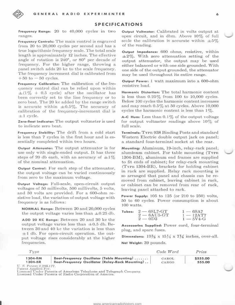
SPE CIFI CATIONS
Frequency Range: 20 to 40,000 cycles in two ranges.
Frequency Controls: The main control is engraved from 20 to 20,000 cycles per second and has a true logarithmic frequency scale. The total scale length is approximately 12 inches. The effective angle of rotation is 240°, or 80° per decade of frequency. For the higher range, throwing a panel switch adds 20 kc to the scale frequency. The frequency increment dial is calibrated from + 50 to - 50 cycles.
Frequency Calibration: The calibration of the frequency control dial can be relied upon within ± (1 % + 0.5 cycle) after the oscillator has been correctly set to the line frequency or to zero beat. The 20 kc added by the range switch is accurate within ±0.5%. The accuracy of calibration of the frequency-increment dial is
±1 cycle.
Zero-Beat Indicator: The output voltmeter is used
to indicate zero beat.
Frequency Stability: The drift from a cold start is less than 7 cycles in the first hour and is essentially completed within two hours.
Output Attenuator: The output attenuator is for use only with single-ended output. It has three
steps of 20 db each, with an accuracy of ±1 %
of the nominal attenuation.
Output Control: For each step of the attenuator, the output voltage can be varied continuously from zero to the maximum voltage.
Output Voltage: Full-scale, open-circuit output voltages of 50 millivolts, 500 millivolts, 5 volts,
and 50 volts are provided. For a 600-ohm re
sistive load, the variation of output voltage with frequency is as follows:
NORMAL Range: Between 20 and 20,000 cycles
the output voltage varies less than ±0.25 db.
ADD 20 KC Range: Between 20 and 30 kc the output voltage varies less than ±0.5 db. Between 30 and 40 kc the variation is less than
± 1 db. For open-circuit operation, the output voltage rises considerably at the higher frequencies.
Type
Output Voltmeter: Calibrated in volts output at open circuit, and in dbm. Above 10% of full scale the calibration is accurate within ±5% of the reading.
Output Impedance: 600 ohms, resistive, within ±2%. With zero attenuation setting of the output attenuator, the output may be used either balanced or with one side grounded. With one side of the output grounded, the attenuator may be used throughout its entire range.
Output Power: 1 watt maximum into a 600-ohm
resistive load.
Harmonic Distortion: The total harmonic content
is less than 0.25% from 100 to 10,000 cycles. Below 100 cycles the harmonic content increases and may reach 0.5% at 50 cycles. Above 10,000
cycles the harmonic content is less than 1 %.
A-C Hum: Less than 0.1 % of the output voltage
for output voltmeter readings above 10% of full scale.
Terminals: TYPE 938 Binding Posts and standard Western Electric double output jack on panel;
a standard four-terminal socket at the rear.
Mounting: Aluminum, 19-inch, relay-rack panel; aluminum cabinet. For table mounting (TYPE
1304-BM), aluminum end frames are supplied to fit ends of cabinet; for relay-rack mounting (TYPE 1304-BR), brackets for holding cabinet in rack are supplied. Relay rack mounting is so arranged that panel and chassis can be removed from cabinet, leaving cabinet in rack, or cabinet can be removed from rear of rack, leaving panel attached to rack.
Power Supply: 105 to 125 (or 210 to 250) volts,
50 to 60 cycles. Power consumption is about 100 watts.
Tubes: 2 -6SL7-GT 2-6AU5-GT 2-0D3
1 - 6SA7 1 - 12AT7 1 - 5V4-G
Accessories Supplied: Power cord, four-terminal
plug, and spare fuses.
Dimensions: 19% x 157.:t'. x 7� inches, over-all.
Net Weight: 39 pounds.
Code Word Price 1304-BM
I Beat-Frequency Oscillator (Table Mounting) . • . • . • .
1304-BR Beat-Frequency Oscillator (Relay-Rack Mounting) . •
CAROL CARGO
$555.00 555.00
U. S. Patent 2.298.177. Patent Applied For. Licensed Under Patents of American Telephone and Telegraph Company. Licensed Under Patents of Radio Corporation of Amerfra .
www.americanradiohistory.com

s
pads, controlled by a switch to give steps of 0, 20, 40, and 60 db attenuation. Over-all attenuator accuracy is ± 1 % of nominal value.
The meter circuit is designed to respond to the average of the voltage waveform and is calibrated in r-m-s voltage. The voltmeter rectifying elements are two 1N54-A germanium diodes used in a full-wave rectifier circuit. Accuracy of the meter indication is ±5% of actual reading.
When the attenuator is set at the +20 db position and the ground strap is disconnected from the lower output terminal, the output circuit is sufficiently well balanced for operation into most balanced audio-frequency equipment. The other attenuator positions should be used only for single-ended output, because the attenuator is inserted only in the lead connected to the upper output terminal.
Zero-Beat Indicator
The output voltmeter is an excellent zero-beat indicator. Thus there is no necessity for any other means. As an accurate calibrating system, a small voltage of power line frequency can be injected to be zero beat with the generated frequency as indicated on the voltmeter. A convenient fifth position of the output attenuator switch is used for this calibration. The frequency is brought to the calibration value by adjustment of the zero control. Warm-up drift is compensated for in the same manner.
Applications
The TYPE 1304-B Beat Frequency Audio Generator is an excellent oscillator for use in practically any application within its frequency range.
JUNE, 1954
It is ideal as a signal source for measurements of amplifier and filter characteristics in the sonic and ultrasonic range, for measuring the amplifier and loudspeaker response of sound reproducing systems, for determining the frequency characteristics of audio transmission lines, networks, meters, and meter circuits, and for many other similar applications where a flat outputvoltag,e characteristic is preferred.
For use with a recorder in these applications, it is particularly advantageous that the frequency dial can be geared to, and rotated by, the mechanism of a recorder, and that the 20-cycles-to-20-kc logarithmic scale of the dial can be synchronized with the logarithmic scale of the recorder paper.
The generator can be used as a signal source, for measurements of harmonic distortion generated in audio-frequency equipment. It can be used as a sine-wave source for modulating r-f signal generators and test oscillators or to trigger pulse generators. A very frequent use is as a generator for audio-frequency bridges. It is also an excellent signal source for psycho-acoustical work.
The metered output voltage makes it convenient for setting operating levels of amplifiers, oscillographs, and other equipment. It can also be used to measure voltage by substitution methods. The frequency of other audio and ultrasonic signals can be measured by use of Lissajous' figures on a cathode-ray oscillograph.
In brief, it is indispensable for use in any audio and ultrasonic work - both for the numerous, small, unexacting jobs that constantly arise, and for those exacting jobs requiring the utmost in performance from all equipment used.
- C. A. WOODWARD
www.americanradiohistory.com

7 JUNE, 1954
BET T ER S ERVICE FOR
CUSTOMERS IN WASHINGTON, D. C., AND VICINITY
-NEW BRANCH OFFICE
To provide better service to our customers in the District of Columbia and adjacent territory, we have opened a branch engineering office at Silver Spring, Maryland.
Through this office we can furnish technical and commercial information promptly about General Radio products and aid in the selection of equipment to meet specific measurement problems.
William R. Saylor, formerly of the Sales Engineering Staff at Cambridge, is Manager of the new office. Mr. Saylor received his S.B. and S.M. degrees from M.I.T. in 1 937 and joined our organization in 1943. Since that date his work has included both development engineering and sales engineering, and he has an extensive knowledge of the performance and application of General Radio instruments.
__ J;r--Willem R. Saylor
The address of the new office is
GENERAL RAD IO COMPANY
8055 13th Street, Silver Spring, Maryland Telephone: JUniper 5-1088
SUMMER CLOSING Vacation
During the weeks of July 25 and August 1, our Manufacturing Departments will be closed for vacation.
There will be business as usual in the Sales Engineering and Commercial Departments. Inquiries, including requests for technical and sales information, will
PROMP T
receive our usual prompt attention. Our Service Department requests
that, because of absences in the manufacturing and repair groups, shipments of material be scheduled to reach us either well before or delayed until after the vacation period.
DELIVERY Remember - you can get delivery from stock on 98% of our standard catalog items.
www.americanradiohistory.com

GENERA L RA D IO EXPERIM ENTER 8
MISC ELLANY
VISITORS: We have welcomed recently at our Cambridge plant the following visitors from foreign countries: D. J. Fuings and Norman Lea, Baddow Research Laboratories, Marconi's Wireless Telegraphy Company, Ltd., Great Baddow, Essex, England; Mr. and Mrs. I-(. L. Nyman of Helsinki, distributors of General Radio products in Finland; E. P. Courtillot, Assistant Chief Engineer of Electronic Group, French Thompson Houston Company, Paris, France; Dr. H. Bienfait and M. M. Jansen-Gration of Phillips Laboratories, Eindthoven, Holland; Ing. Virgilio Floriana, President, and L. Confalonieri of S.P.A. "Telettra," Milan, Italy; Professor Gino
Morandi of the University of Bologna, Bologna, Italy; Gunner Lindstrom and Dag Hartman, Production Supervisor, Saab Aircraft Company, Linkoping,
Sweden; Dr. Y. Tsuji, Sub-Manager of
the Engineering Division, Sumitomo
Electric Industries, Ltd., Osaka, Japan;
S. Nakamura and K. Ozawa of Meiden
sha Electric Manufacturing Company,
Ltd., Tokyo, Japan; T. Tsumura, Chief,
Engineering Section of Electronic Prod
ucts Works, Mitsubishi Electric Manu
facturing Company, Amagasaki, Japan;
Dr. Koji Kobayashi, Vice-President and Works Manager, Nippon Electric Com
pany, Ltd., Minatoku, Tokyo, Japan.
THE General Radio EXPERIMENTER is mailed without charge each
month to engineers, scientists, technicians, and others interested
in electronic techniques in measurement. When sending requests for
subscriptions and address-change notices, please supply the following
information: narne, company address, type of business company is en
gaged in, and title or position of individual.
GENERAL RADIO COMPANY 275 MASSACHUSETTS AVENUE
CAMBRIDGE 39 MASSACHUSETTS TELEPHONE: TRowbridge 6-4400
BRANCH ENGIN E ERING OFFICES NEW YORK 6, NEW YORK
90 WEST STREET
T EL.-W Orth 4-2722
CHICAGO 5, ILLINOIS
920 S OUTH MICHIGAN AVENUE
TEL.-WAbash 2-3820
L OS ANGE LES 38, CALIFORNI A
1000 NORTH SEW ARD STREET
TEL.-HOllywood 9-6201
SILVER SPRI NG, MA RYLAND
8055 13th ST REET
TEL.-JUniper 5·1088
R E PAIR S E RVIC E S WEST COAST
W E S T E R N I N S T R U M E N T C 0. 826 NORTH VICTORY BOULEVARD
BURBANK, CALIFORNIA
TEL.-Vlcloria 9·3013
CANADA BAYLY ENGINEERING, LTD.
FIRST STREET
AJAX, ONTARIO
TEL.-Toronto EMpire 8·6866
www.americanradiohistory.com