The two- or three-piece shut-off valve for high ... · » Split body ball valve with 2- or 3-piece...
28
SCHUCK TYPE S BALL VALVE The two- or three-piece shut-off valve for high-maintenance and demanding media. SIL SUITABLE
Transcript of The two- or three-piece shut-off valve for high ... · » Split body ball valve with 2- or 3-piece...

06.2011 DE MAR00080 1
SCHUCK TYPE S BALL VALVEThe two- or three-piece shut-off valve forhigh-maintenance and demanding media.
SIL SUITABLE

02 06.2011 DE MAR00080
SCHUCK TYPE S BALL VALVEThe two- or three-piece shut-off valve forhigh-maintenance and demanding media.
WWW.SCHUCK-TRANSPORT.COM
APPLICATIONSIsolating valve for above-ground applications in plants, on stations, platforms, pumping stations, etc.
Min. temp. range -60° C to +120° C
Standard temp. range -29° C to +120° C
Max. temp. range -29° C to +200° C
MANUFACTURINGManufacturing, testing and design
standards EN 12266 -1 API 6D ISO 14313 / API 6D, ASME B16.34, ASME Sec. VIII Div.1
Leak, functioning and fire safety
ISO5208, DIN 3230 T5 PG3 for gas, ISO 10497 / API 607
For futher information see the glossary.
06.2011 DE MAR00080 03
COMPANY TRANSPORT DISTRIBUTION ACTUATORS SERVICE
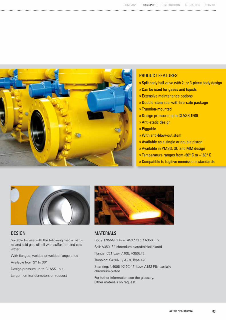
PRODUCT FEATURES
» Split body ball valve with 2- or 3-piece body design
» Can be used for gases and liquids
» Extensive maintenance options
» Double-stem seal with fire-safe package
» Trunnion-mounted
» Design pressure up to CLASS 1500
» Anti-static design
» Piggable
» With anti-blow-out stem
» Available as a single or double piston
» Available in PMSS, SO and MM design
» Temperature ranges from -60° C to +160° C
» Compatible to fugitive emmissions standards
DESIGNSuitable for use with the following media: natu-ral and acid gas, oil, oil with sulfur, hot and cold water.
With flanged, welded or welded flange ends
Available from 2“ to 36“
Design pressure up to CLASS 1500
Larger nominal diameters on request
MATERIALSBody: P355NL1 bzw. A537 CI.1 / A350 LF2
Ball: A350LF2 chromium-plated/nickel-plated
Flange: C21 bzw. A105, A350LF2
Trunnion: S420NL / A276 Type 420
Seat ring: 1.4006 (X12Cr13) bzw. A182 F6a partially chromium-plated
For futher information see the glossary. Other materials on request.

04 06.2011 DE MAR00080
SCHUCK TYPE S BALL VALVETyp S 2“ to 3“, Typ S 4“ to 36“Type overview and design
WWW.SCHUCK-TRANSPORT.COM
SERIES 2” TO 3”2-part body with flanges or weld ends
Floating ball plug 2” above 100 bar
Trunnion-mounted (≥NPS2) with self-centring seating ring system with pre-tensioned spring elements
Main seal: soft sealing (SO), primary metal seconda-ry soft (PMSS) or metal to metal sealing (MM)
Operating stem protected against blow-outs
Double-trunnion seal with fire-safe seal
Swivel angle limited by stop washers (for design with actuating lever)
SERIES 4“ TO 36“*3-part body with flanges or weld ends
Secondary sealant injection for seats and operating stem
Draining and venting connections
Trunnion-mounted ball plug
Anti blow out stem
Triple trunnion seal with additional fire-safe package
Main seal: PMSS, SO, MM
Main seal: double piston / single piston
*Larger nominal diameters on request
TOCLASS
2500
TOCLASS
2500

06.2011 DE MAR00080 05
TOP FLANGEActuator connecting interface
THREAD BOLTTo fasten the individual body components
ACTUATOR INTERFACE
SEAT RING
CENTRAL BODYTo incorporate the ball plug
OPERATING STEMTo incorporate the actuator to transmit the torque
LEFT-HAND BODYFlange for connection to the pipeline system
SEAT RING
BALL PLUGRIGHT-HAND BODYFlange for connection to the pipeline system
COMPANY TRANSPORT DISTRIBUTION ACTUATORS SERVICE

06 06.2011 DE MAR00080
DESCRIPTIONDifferent sealing systems are available depending on applications. Our range of products offers soft-sealing and metallic-sealing systems as well as a primary metallic/secondary soft-sealing system with an integrated seal ring which we developed oursel-ves. This system is particularly resilient and reliable.
CONFIGURATIONSPrimary metallic/secondary soft-sealing seating ring (PMSS) metallic seal plus elastomer seal
Wear-resistant and not sensitive to dirt
Schuck standard, broad range of applications
Soft sealing seating ring (SO) A seal ring made of plastic is used for sealing
Larger variety of materials available (PTFE, PA, PEEK, etc.)
High temperatures
Low torque
For high pressures, special media
Variable sealing material and thus optimum for many types of media
Metal to metal sealing seating ring (MM) A metallic contact is used for sealing
High resistance to wear and not sensitive to dirt and deposits
Suitable for high pressures
Wide temperature range
SCHUCK TYPE S BALL VALVEDesign features Sealing systems
WWW.SCHUCK-TRANSPORT.COM
Top left: Schuck seat ring
Top right: primary metallic secondary soft-sealing system
Bottom left: soft sealing system
Bottom right: metal to metal system
06.2011 DE MAR00080 07
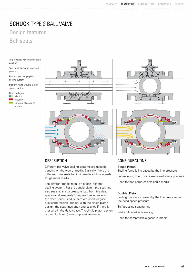
DESCRIPTIONDifferent ball valve sealing systems are used de-pending on the type of media. Basically, there are different main seals for liquid media and main seals for gaseous media.
The different media require a special adapted sealing system. For the double piston, the seat ring also seals against a pressure load from the dead space (or alternatively for a pressure increase in the dead space), and is therefore used for gase-ous (compressible) media. With the single piston design, the seat rings open and balance if there is pressure in the dead space. The single piston design is used for liquid (non-compressible) media.
CONFIGURATIONS Single Piston Sealing force is increased by the line pressure
Self-relieving due to increased dead space pressure
Used for non-compressible liquid media
Double Piston Sealing force is increased by the line pressure and the dead space pressure
Self-pressing seating ring
Inlet and outlet side sealing
Used for compressible gaseous media
SCHUCK TYPE S BALL VALVEDesign features Ball seats
COMPANY TRANSPORT DISTRIBUTION ACTUATORS SERVICE
Top left: Ball valve flow in open position
Top right: Ball valve in closed position
Bottom left: Single piston sealing system
Bottom right: Double piston sealing system
Drawing legend: Medium Pressure Differential pressure surface

08 06.2011 DE MAR00080
SCHUCK TYPE S BALL VALVEDesign features Venting, draining
WWW.SCHUCK-TRANSPORT.COM
DESCRIPTIONDifferent attachments can be removed for emptying and venting the dead space. Just the right attach-ment is available for any application and any custo-mer request, from the lowest-cost plug variation, continuing with the bleeder plug, up to a ball valve.
Here, the connector on the bottom is for draining, and the connector on top is for venting.
Draining and venting are used, for example, for service work in order to free the dead space of pressure and condensate. These attachments are also used for pressure and leak testing, and are thus an indispensable instrument for a safe and reliable ball valve.
ABOVE-GROUND CONFIGURATION Venting and draining plug, bleeder plug, ball valve
Top left: Venting ball valve of an above-ground ball valve
Top right: The different connec-tors for draining/venting for an above-ground ball valve
06.2011 DE MAR00080 09
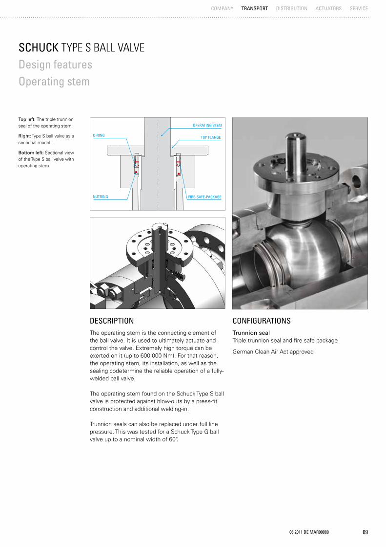
Top left: The triple trunnion seal of the operating stem.
Right: Type S ball valve as a sectional model.
Bottom left: Sectional view of the Type S ball valve with operating stem
SCHUCK TYPE S BALL VALVEDesign features Operating stem
DESCRIPTIONThe operating stem is the connecting element of the ball valve. It is used to ultimately actuate and control the valve. Extremely high torque can be exerted on it (up to 600,000 Nm). For that reason, the operating stem, its installation, as well as the sealing codetermine the reliable operation of a fully-welded ball valve.
The operating stem found on the Schuck Type S ball valve is protected against blow-outs by a press-fit construction and additional welding-in.
Trunnion seals can also be replaced under full line pressure. This was tested for a Schuck Type G ball valve up to a nominal width of 60”.
CONFIGURATIONSTrunnion seal Triple trunnion seal and fire safe package
German Clean Air Act approved
COMPANY TRANSPORT DISTRIBUTION ACTUATORS SERVICE
NUTRING
O-RING
OPERATING STEM
TOP FLANGE
FIRE-SAFE-PACKAGE

10 06.2011 DE MAR00080
WWW.SCHUCK-TRANSPORT.COM
SCHUCK TYPE S BALL VALVEDesign features Outside coating
Coatings for high corrosiveness > 240μm Outer coating “C4” ISO 12944-2
Temperature range: up to 120°C
Fields of application: above ground, industrial areas and coastal regions with moderate salt load
Coatings for very high corrosiveness > 300μm Outer coating “C5” ISO 12944-2
Temperature range: up to 120°C
Fields of application: above ground, coastal and offshore areas with high salt load
COATING SYSTEMS Sigmadur Dimensions: 50μm + 80 μm
Temperature range: -30°C to +160°C
Fields of application: above-ground and high tempe-ratures
PROTEGOL UR 32-55 (Polyurethan) > 1,5 mm Temperature range:: -30°C to +80°C (briefly up to 110 °C)
Fields of application: below-ground, resistance to water, acids, alkaline solutions, and oil
DESCRIPTIONEven a robust component like the fully-welded Schuck Type S ball valve must be protected against the effects of weather and mechanical damage above ground and also for below-ground installation. The coating is decisively responsible for this impor-tant protection. It is applied to the ball valve at the end of the production chain using a predetermined minimum layer thickness.
The coating standards of our Schuck ball valves meet all demands.
All coatings are inspected and approved by an in-house expert or by an expert hired by the customer.
Through these measures, we can guarantee the highest degree of protection against corrosion for your ball valve.
The outer coating can be implemented in any RAL color at your request.
CONFIGURATIONSCoatings for moderate corrosiveness > 200μm Außenbeschichtung Outer coating “C3” ISO 12944-2
Temperature range: up to 120°C
Fields of application: above ground, urban and industrial atmospheres, moderate pollution from sulfur dioxide. Coastal regions with low salt load
Left: The Schuck standard coating in yellow
Right: Schuck Type S ball valve with outer coat in any RAL tone requested by the customer

06.2011 DE MAR00080 11
AVAILABLE
ACCESSORIES
SCHUCK TYPE S BALL VALVEAccessoriesInner coating
COMPANY TRANSPORT DISTRIBUTION ACTUATORS SERVICE
CONFIGURATIONSCladding e.g. Inconel, AISI 316, tungsten carbide, nickel, chrome, others on request
For gas standard without inner coating
Other inner coatings for the respective media on request
DESCRIPTIONThe medium-compatible inner coating gives the ball valve the perfect inner skin that protects it against damage caused by the medium and prevents any possible contamination of the medium (e.g. for drinking water).
The possibility of armoring through cladding is par-ticularly important for the Type S ball valve, mainly for special applications like sour gas, for example. Depending on the application and customer require-ments, the lining applied through cladding protects the inside of the ball valve against aggressive and corrosive media and wear due to its material, thick-ness and the clad area.
All coatings are inspected and approved by an in-house expert or by third party.
Through these measures, we can guarantee the highest degree of protection against corrosion for your ball valve.
Left: Inner coating in a Schuck Type S ball valve
Right: Inner coating in a Schuck Type S ball valve with view of the ball

12 06.2011 DE MAR00080
CONFIGURATIONSSecondary sealant injection (standard)
Injection head
Check valve
Secondary sealant injection
Double injection head
Check valve
Secondary sealant injection
Injection head
Two check valves
Secondary sealant injection
Injection head
Block ball valve
Check valve
DESCRIPTIONSplit Body Type S ball valves up to NPS4 are by default equipped with injection heads for injecting a secondary sealant. In an emergency, a suitable secondary sealant can be injected if there is a leak at the seating rings or the actuator trunnions.
The choice of sealant is based on the medium, tem-perature and pressure. Very high pressures may be needed for injection depending on the sealant. The sealant press and all the lines must be designed for that pressure (up to 1000 bar).
SCHUCK TYPE S BALL VALVEDesign features Secondary injection of sealant
WWW.SCHUCK-TRANSPORT.COM
Left: Injection heads for a above-ground ball valve type S for injection.
Right: The different connec-tors for the secondary sealant injection for an above-ground ball valve.
06.2011 DE MAR00080 13
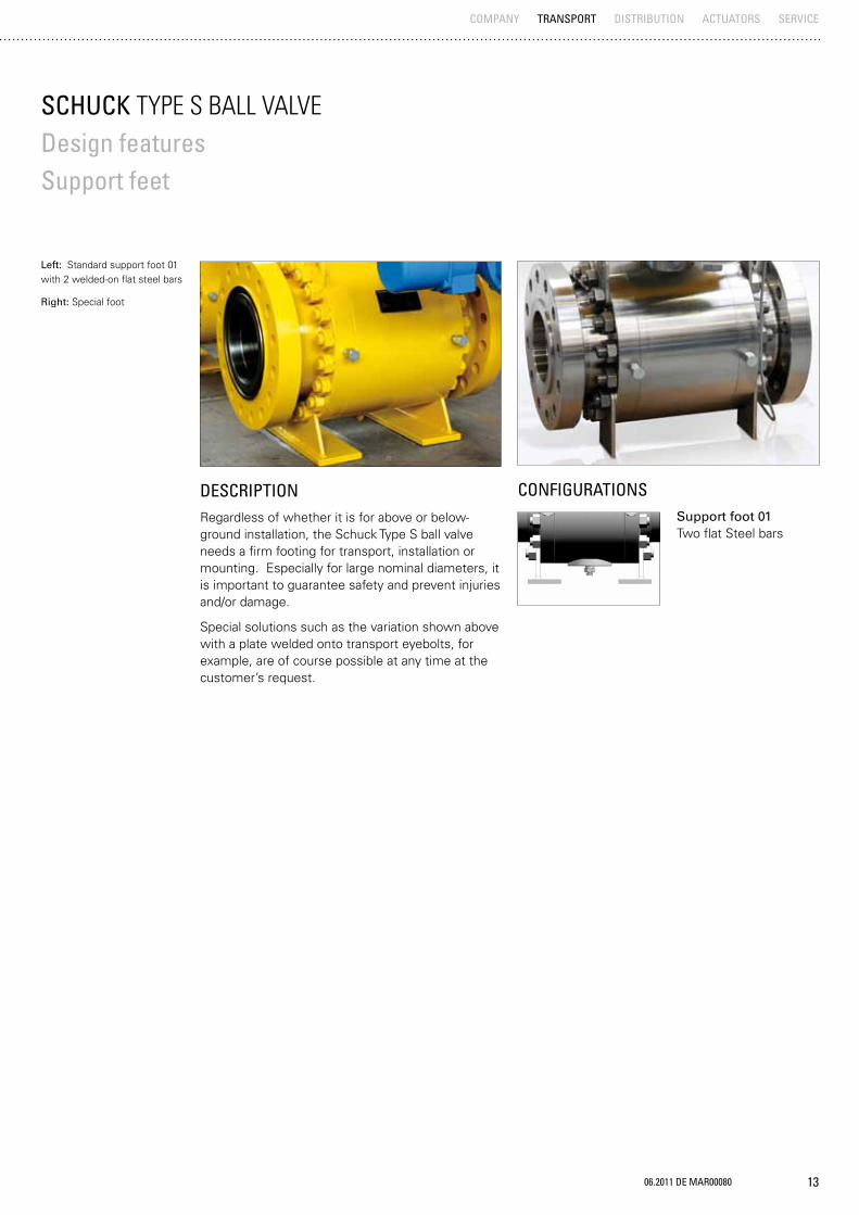
CONFIGURATIONSSupport foot 01 Two flat Steel bars
DESCRIPTIONRegardless of whether it is for above or below-ground installation, the Schuck Type S ball valve needs a firm footing for transport, installation or mounting. Especially for large nominal diameters, it is important to guarantee safety and prevent injuries and/or damage.
Special solutions such as the variation shown above with a plate welded onto transport eyebolts, for example, are of course possible at any time at the customer’s request.
SCHUCK TYPE S BALL VALVEDesign features Support feet
COMPANY TRANSPORT DISTRIBUTION ACTUATORS SERVICE
Left: Standard support foot 01 with 2 welded-on flat steel bars
Right: Special foot
14 06.2011 DE MAR00080
AVAILABLE
ACCESSORIES
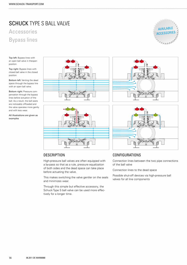
CONFIGURATIONSConnection lines between the two pipe connections of the ball valve
Connection lines to the dead space
Possible shut-off devices via high-pressure ball valves for all line components
DESCRIPTIONHigh-pressure ball valves are often equipped with a by-pass so that as a rule, pressure equalization of both sides and the dead space can take place before actuating the valve.
This makes switching the valve gentler on the seals and minimizes wear.
Through this simple but effective accessory, the Schuck Type S ball valve can be used more effec-tively for a longer time.
SCHUCK TYPE S BALL VALVEAccessoriesBypass lines
WWW.SCHUCK-TRANSPORT.COM
Top left: Bypass lines with an open ball valve in theopen position.
Top right: Bypass lines with closed ball valve in the closed position.
Bottom left: Venting the dead space through the bypass line with an open ball valve.
Bottom right: Pressure com-pensation through the bypass lines before actuation of the ball. As a result, the ball seats are noticeably offloaded and the valve operates more gently and with less wear.
All illustrations are given as examples

06.2011 DE MAR00080 15
AVAILABLE
ACCESSORIES
CONFIGURATIONSBoroscope opening Open position marking
Closed position marking
Boroscope sleeve for insertion of the boroscope
Boroscope Long version D8 x 465 mm
Short version D8 x 200 mm
Accessory: battery operated handheld light source for the boroscope
DESCRIPTIONThe positioning of the ball plays a decisive role in guaranteeing safe operation of the Schuck Type S ball valve. After installation of the valve, the bo-roscope opening makes it possible to accurately check the ball position in the end position. Indepen-dent of the actuator, both the open position as well as the closed position of the shut-off valve can be set and checked.
There are markings on the actuator trunnion for the open and closed position. With the help of the boroscope opening and the boroscope, the marking and hence the exact position of the ball in the open and closed position can be determined optically. If the ball valve is used in an above ground variation, then the boroscope opening is on the gear plate. If the valve is used below-ground, then the boroscope opening is on the pipe stands.
Generally, adjusting the open and closed position using the boroscope opening is a more exact set-ting than using the end position display on the top side of the gear unit.
The associated boroscope has cross hairs that guarantee exact setting and checking of the end position of the ball. In addition, the boroscope has a lighting option, so that the markings on the actuator trunnion are clearly visible.
COMPANY TRANSPORT DISTRIBUTION ACTUATORS SERVICE
SCHUCK TYPE S BALL VALVEAccessoriesBoroscope with boroscope opening and markings
Left: Setup of the boroscope opening with the position markings and an inserted boroscope.
Right: Boroscope with opening for battery operated handheld light source
OPEN POSITION
CLOSED POSITION
BOROSCOPEFITTING
BOROSCOPE
ACTUATOR TRUNNIONS

16 06.2011 DE MAR00080
WWW.SCHUCK-TRANSPORT.COM
SCHUCK TYPE S BALL VALVEMaintenance and service
Top left: Schuck Service assignment – flight of Schuck service specialists into Novy Urengoy, Russia for mainte-nance work
Top right: Schuck Servicecar – always ready for action on-site
SERVICEMaintenance and servicing Condition analysis Maintenance plans Maintenance
Repairs Project planning Logistics planning Spare parts supply Spare parts processing Spare parts production Repairs Recommissioning
Conversions Project planning Logistics planning Parts provision Part production Part reconstruction Conversion work Initial operation
Spare and new parts Spare parts New parts Processing
Counseling and Training Modification consulting Realisation consulting Product trainings Startup procedure trainings Service trainings
DESCRIPTIONOur job isn‘t finished when our products have been dispatched. Safety-critical components such as our shut-off valves or Schuck actuator systems need to be properly installed, initialized and maintained.
Maintenance is particularly critical in the calculation and adherence to probabilities of failure (SIL values). It is not only the process itself that is critical, but particularly the quality of the maintenance work performed.
The Schuck Service division assumes these duties. Internationally. Reliably. Expertly. Our range of servi-ces covers everything – from maintenance to repair, from renovation to replacement, from new parts to consulting and training. This applies not only to Schuck‘s own products, but also to many third-party manufacturers.
The team also performs all repair and maintenance work, including procurement of spare parts, for ball valves manufactured by Borsig – in accordance with company tradition. If the necessary spare parts are no longer available, we specially produce these on the basis of available documentation ourselves.
Our international team, with service offices in India, China, Kazakhstan, Uzbekistan and Germany, is always up-to-date, and works both on and off-shore.

06.2011 DE MAR00080 17
COMPANY TRANSPORT DISTRIBUTION ACTUATORS SERVICE
18 06.2011 DE MAR00080
AVAILABLE
ACCESSORIES
WWW.SCHUCK-TRANSPORT.COM
CONFIGURATIONSGas over oil actuator system - Type G
Pneumatic actuators systems -Type K
Electro-hydraulic actuator system - Type C
Electro-hydraulic compact control - Type SHC
Direct gas system -Type KY
Electro-hydraulic actuator system -Type X
Manual actuator
Electric actuator systems
Electro-hydraulic spring return - Type C7/C8
Pneumatic spring-return - Type K7/K8
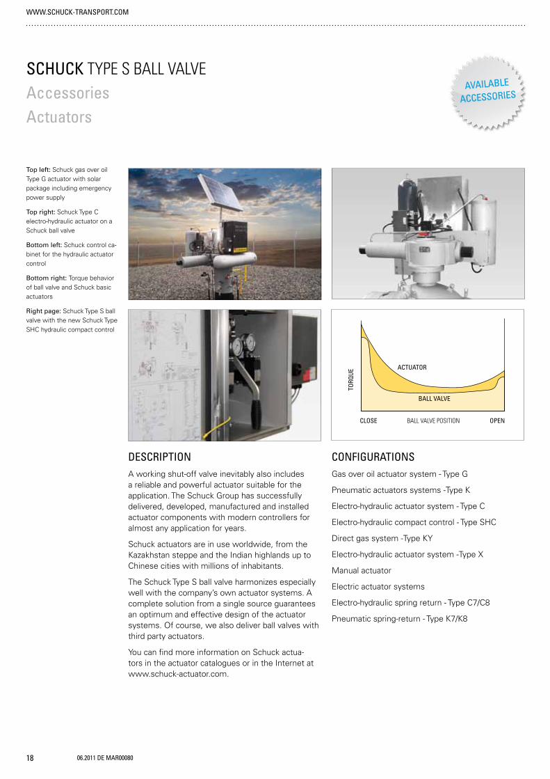
DESCRIPTIONA working shut-off valve inevitably also includes a reliable and powerful actuator suitable for the application. The Schuck Group has successfully delivered, developed, manufactured and installed actuator components with modern controllers for almost any application for years.
Schuck actuators are in use worldwide, from the Kazakhstan steppe and the Indian highlands up to Chinese cities with millions of inhabitants.
The Schuck Type S ball valve harmonizes especially well with the company’s own actuator systems. A complete solution from a single source guarantees an optimum and effective design of the actuator systems. Of course, we also deliver ball valves with third party actuators.
You can find more information on Schuck actua-tors in the actuator catalogues or in the Internet at www.schuck-actuator.com.
SCHUCK TYPE S BALL VALVEAccessoriesActuators
Top left: Schuck gas over oil Type G actuator with solar package including emergency power supply
Top right: Schuck Type C electro-hydraulic actuator on a Schuck ball valve
Bottom left: Schuck control ca-binet for the hydraulic actuator control
Bottom right: Torque behavior of ball valve and Schuck basic actuators
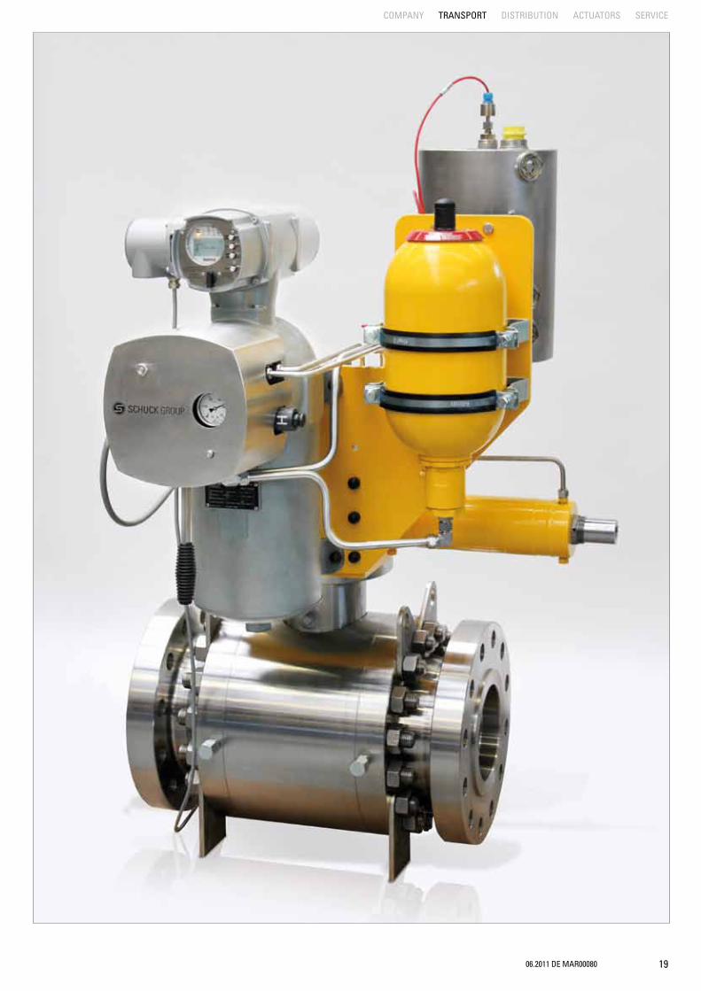
Right page: Schuck Type S ball valve with the new Schuck Type SHC hydraulic compact control
ACTUATOR
TORQ
UE
BALL VALVE
CLOSE BALL VALVE POSITION OPEN
06.2011 DE MAR00080 19
COMPANY TRANSPORT DISTRIBUTION ACTUATORS SERVICE

20 06.2011 DE MAR00080
SCHUCK TYPE S BALL VALVECLASS 150With flange or weld end
WWW.SCHUCK-TRANSPORT.COM
Schuck ball valve type S / CLASS 150NPS DN CLASS BL RF BL WE BL RTJ H1 H22 50 150 178 216 191 90 130
3 80 150 203 283 216 110 170
4 100 150 229 305 241 190 185
6 150 150 394 457 406 230 280
8 200 150 457 521 470 275 330
10 250 150 533 559 546 315 370
12 300 150 610 635 622 355 415
14 350 150 686 762 699 400 460
16 400 150 762 838 775 450 490
18 450 150 864 914 876 490 550
20 500 150 914 991 927 540 605
22 550 150 - - - 590 670
24 600 150 1067 1143 1080 650 725
26 650 150 1143 1245 - 690 750
28 700 150 1245 1346 - 740 800
30 750 150 1295 1397 - 770 820
32 800 150 1372 1524 - 825 850
34 850 150 1473 1626 - 850 870
36 900 150 1524 1727 - 870 900
40 1000 150
42 1050 150
44 1100 150
48 1200 150
56 1500 150
NPS nominal diameters in inch
DN nominal width
CLASS Pressure rating
BL RF constr. length RF Flansch
BL WE construction length Weld End
BL RTJ constr. length RTJ Flansch
H1 High 1
H2 High 2
By manufacturer‘s standardresp. on request.
H2
H1
BL
H1
H2

06.2011 DE MAR00080 21
SCHUCK TYPE S BALL VALVECLASS 300With flange or weld end
COMPANY TRANSPORT DISTRIBUTION ACTUATORS SERVICE
Schuck ball valve type S / CLASS 300NPS DN CLASS BL RF BL WE BL RTJ H1 H22 50 300 216 216 232 90 130
3 80 300 283 283 298 110 170
4 100 300 305 305 321 190 185
6 150 300 403 457 419 230 280
8 200 300 502 521 518 275 330
10 250 300 568 559 584 315 370
12 300 300 648 635 664 355 415
14 350 300 762 762 778 400 460
16 400 300 838 838 854 450 490
18 450 300 914 914 930 490 550
20 500 300 991 991 1010 540 605
22 550 300 1092 1092 1114 590 670
24 600 300 1143 1143 1165 650 725
26 650 300 1245 1245 1270 690 750
28 700 300 1346 1346 1372 740 800
30 750 300 1397 1397 1422 770 820
32 800 300 1524 1524 1553 825 850
34 850 300 1626 1626 1654 850 870
36 900 300 1727 1727 1756 870 900
40 1000 300
42 1050 300
44 1100 300
48 1200 300
56 1500 300
NPS nominal diameters in inch
DN nominal width
CLASS Pressure rating
BL RF constr. length RF Flansch
BL WE construction length Weld End
BL RTJ constr. length RTJ Flansch
H1 High 1
H2 High 2
By manufacturer‘s standardresp. on request.
H2
H1
BL
H1
H2

22 06.2011 DE MAR00080
SCHUCK TYPE S BALL VALVECLASS 400With flange or weld end
WWW.SCHUCK-TRANSPORT.COM
Schuck ball valve type S / CLASS 400NPS DN CLASS BL RF BL WE BL RTJ H1 H24 100 400 406 406 410 190 185
6 150 400 495 495 498 230 280
8 200 400 597 600 600 275 330
10 250 400 673 673 676 315 370
12 300 400 762 762 765 355 415
14 350 400 826 826 829 400 460
16 400 400 902 902 905 450 490
18 450 400 978 978 981 490 550
20 500 400 1054 1054 1060 540 605
22 550 400 1143 1143 1153 590 670
24 600 400 1232 1232 1241 650 725
26 650 400 1308 1308 1321 690 750
28 700 400 1397 1397 1410 740 800
30 750 400 1524 1524 1537 770 820
32 800 400 1651 1651 1667 825 850
34 850 400 1778 1778 1794 850 870
36 900 400 1880 1880 1895 870 900
40 1000 400
42 1050 400
44 1100 400
48 1200 400
56 1500 400
NPS nominal diameters in inch
DN nominal width
CLASS Pressure rating
BL RF constr. length RF Flansch
BL WE construction length Weld End
BL RTJ constr. length RTJ Flansch
H1 High 1
H2 High 2
By manufacturer‘s standardresp. on request.
H2
H1
BL
H1
H2

06.2011 DE MAR00080 23
COMPANY TRANSPORT DISTRIBUTION ACTUATORS SERVICE
SCHUCK TYPE S BALL VALVECLASS 600With flange or weld end
Schuck ball valve type S / CLASS 600NPS DN CLASS BL RF BL WE BL RTJ H1 H22 50 600 292 292 295 90 130
3 80 600 356 356 359 110 170
4 100 600 432 432 435 190 185
6 150 600 559 559 562 230 280
8 200 600 660 660 664 275 330
10 250 600 787 787 791 315 370
12 300 600 838 838 841 355 415
14 350 600 889 889 892 400 460
16 400 600 991 991 994 450 490
18 450 600 1092 1092 1095 490 550
20 500 600 1194 1194 1200 540 605
22 550 600 1295 1295 1305 590 670
24 600 600 1397 1397 1407 650 725
26 650 600 1448 1448 1461 690 750
28 700 600 1549 1549 1562 740 800
30 750 600 1651 1651 1664 770 820
32 800 600 1778 1778 1794 825 850
34 850 600 1930 1930 1946 850 875
36 900 600 2083 2083 2099 870 900
40 1000 600
42 1050 600
44 1100 600
48 1200 600
56 1500 600
NPS nominal diameters in inch
DN nominal width
CLASS Pressure rating
BL RF constr. length RF Flansch
BL WE construction length Weld End
BL RTJ constr. length RTJ Flansch
H1 High 1
H2 High 2
By manufacturer‘s standardresp. on request.
H2
H1
BL
H1
H2

24 06.2011 DE MAR00080
H2
H1
BL
H1
H2
SCHUCK TYPE S BALL VALVECLASS 900With flange or weld end
WWW.SCHUCK-TRANSPORT.COM
Schuck ball valve type S / CLASS 900NPS DN CLASS BL RF BL WE BL RTJ H1 H22 50 900 368 368 371 110 150
3 80 900 381 381 384 140 200
4 100 900 457 457 460 195 185
6 150 900 610 610 613 240 285
8 200 900 737 737 740 285 245
10 250 900 838 838 841 360 385
12 300 900 965 965 968 410 425
14 350 900 1029 1029 1038 440 465
16 400 900 1130 1130 1140 465 505
18 450 900 1219 1219 1232 505 565
20 500 900 1321 1321 1334 560 625
22 550 900 - - - 620 700
24 600 900 1549 1549 1568 675 750
26 650 900 1651 - 1673 720 785
28 700 900 - - - 760 825
30 750 900 1880 - 1902 810 855
32 800 900 - - - 840 870
34 850 900 - - - 870 885
36 900 900 2286 - 2315 900 920
40 1000 900
42 1050 900
44 1100 900
48 1200 900
48 1500 900
NPS nominal diameters in inch
DN nominal width
CLASS Pressure rating
BL RF constr. length RF Flansch
BL WE construction length Weld End
BL RTJ constr. length RTJ Flansch
H1 High 1
H2 High 2
By manufacturer‘s standardresp. on request.

06.2011 DE MAR00080 25
COMPANY TRANSPORT DISTRIBUTION ACTUATORS SERVICE
SCHUCK TYPE S BALL VALVECLASS 1500With flange or weld end
Schuck ball valve type S / CLASS 1500NPS DN CLASS BL RF BL WE BL RTJ H1 H22 50 1500 368 368 371 110 150
3 80 1500 470 470 473 140 200
4 100 1500 546 546 549 195 185
6 150 1500 705 705 711 240 285
8 200 1500 832 832 841 285 245
10 250 1500 991 991 1000 360 385
12 300 1500 1130 1130 1146 410 425
14 350 1500 1257 1257 1276 445 465
16 400 1500 1384 1384 1407 465 505
18 800 1500 1537 - 1559 510 565
20 500 1500 1664 - 1686 560 625
22 550 1500 - - - 620 700
24 600 1500 - - - 675 750
26 600 1500 1943 - 1972 735 875
28 700 1500
30 750 1500
32 800 1500
34 850 1500
36 900 1500
40 1000 1500
42 1050 1500
44 1100 1500
48 1200 1500
56 1500 1500
NPS nominal diameters in inch
DN nominal width
CLASS Pressure rating
BL RF constr. length RF Flansch
BL WE construction length Weld End
BL RTJ constr. length RTJ Flansch
H1 High 1
H2 High 2
By manufacturer‘s standardresp. on request..
H2
H1
BL
H1
H2
26 06.2011 DE MAR00080
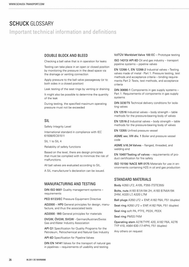
SCHUCK GLOSSARYImportant technical information and definitions
DOUBLE BLOCK AND BLEEDChecking a ball valve that is in operation for leaks
Testing can take place in an open or closed position by monitoring the pressure in the dead space via the drainage or venting connection
Apply pressure to the ball valve passageway (or to both sides in a closed position)
Leak testing of the seat rings by venting or draining
It might also be possible to determine the quantity of the leak
During testing, the specified maximum operating pressure must not be exceeded
SILSafety Integrity Level
International standard in compliance with IEC 61508/IEC61511
SIL 1 to SIL 4
Reliability of safety functions
Based on the level, there are design principles that must be complied with to minimize the risk of malfunctions.
All ball valves are evaluated according to SIL.
A SIL manufacturer’s declaration can be issued.
MANUFACTURING AND TESTINGDIN ISO 9001 Quality management systems – requirements
PED 97/23/EC Pressure Equipment Directive
AD2000 – HP0 General principles for design, manu-facture, and thus the associated tests
AD2000 - W0 General principles for materials
DVGW, ÖVGW, SVGW - German/Austrian/Swiss Gas and Water Industry Association
API Q1 Specification for Quality Programs for the Petroleum, Petrochemical and Natural Gas Industry
API 6D Specification for Pipeline Valves
DIN EN 14141 Valves for the transport of natural gas in pipelines – requirements of usability and testing
VdTÜV Merkblatt Valve 100 EC – Prototype testing
ISO 14313/ API 6D Oil and gas industry – transport pipeline systems – pipeline valves
EN 12266-1, EN 12266-2 Industrial valves – Testing valves made of metal - Part 1: Pressure testing, test methods and acceptance criteria – binding require-ments Part 2: Tests, test methods, and acceptance criteria
DIN 30690-1 Components in gas supply systems – Part 1: Requirements of components in gas supply systems
DIN 3230 T5 Technical delivery conditions for isola-ting valves
EN 12516 Industrial valves – body strength – table methods for the pressure-bearing body of valves
EN 12516-2 Industrial valves – body strength – table methods for the pressure-bearing body of valves
EN 13355 Unfired pressure vessel
ASME sec. VIII div. 1 Boiler and pressure vessel code
ASME b16.34 Valves – flanged, threaded, and welding end
EN 10497 Testing of valves – requirements of pro-duct certification for fire safety
ISO 15156/ NACE MR 0175 Materials for use in en-vironments containing H2S in oil and gas production
STANDARD MATERIALSBody A350 LF2, A105, P355 (TSTE355)
Bolts, nuts A193 B7/A194 2H, A193 B7M/A194 2HM, A320 L7, A320 L7M
Ball plugs A350 LF2 + ENP, A182 F6A, F51 (duplex)
Seat ring A350 LF2 + ENP, A182 F6A, F51 (duplex)
Seal ring soft PA, PTFE, PEEK, PEEK
Seal ring PMSS FKM
Operating stem A276 TYPE 420, A182 F6A, A276 TYP 410, A564 630 (17-4PH), F51 (duplex)
Any others on request
WWW.SCHUCK-TRANSPORT.COM

06.2011 DE MAR00080 27
COMPANY TRANSPORT DISTRIBUTION ACTUATORS SERVICE
LIST OF ABBREVIATIONS
DN Nominal diameter
SW Spanner width
PN Nom. pressure
PT Test pressure
CL Pressure rating based on American standard
PS/MOP Maximum operating pressure
FB Floating mounted ball
TM Trunnion-mounted ball
RF Raced face flange
RTJ Ring type joint flange
SP Single piston
DP Double piston
PMSS Primary metallic/secondary soft sealing
MM Metallic sealing
SO Soft sealing
PUR Polyurethane
SI Secondary sealant complete (standard as of 6”)
SIS Secondary sealant only on seating ring
SIT Secondary sealant only on actuator trunnion
oSI Without sealant
DIN Deutsches Institut für Normung (German Standardization Institute)
EN European Norm (Standard)
ISO International Standards Organization
API American Petroleum Institute
ASME American Society of Mechanical
Engineers
Mgmt Guide Line
ANSI American National Standards Institute
DGRL/ PED Pressure Equipment Directive
DVGW Deutsche Vereinigung des Gas- und Wasserfaches e.V. (German Gas and Water Industry Association)
SCHUCK GROUP
Franz Schuck GmbHDaimlerstraße 4–789555 Steinheim, Deutschland
Fon +49. (0) 7329. 950 -0Fax +49. (0) 7329. 950 -161
We manufacture and distribute components for connecting pipeline systems in more than 50 countries, with 5 international offices and over 40 years of experience.
Do you want to find out more about a specific product?Give us a call, or visit to our website at www.schuck-group.com.
06.2
011
DE M
AR00
080