THE TUNNELS IN GUADARRAMA FOR THE HIGH SPEED … GUADARRAMA … · · 2017-07-06The tunnels in...
12
THE TUNNELS IN GUADARRAMA FOR THE HIGH SPEED RAILWAY
Transcript of THE TUNNELS IN GUADARRAMA FOR THE HIGH SPEED … GUADARRAMA … · · 2017-07-06The tunnels in...
THE TUNNELS IN GUADARRAMA FOR THE HIGH SPEED RAILWAY
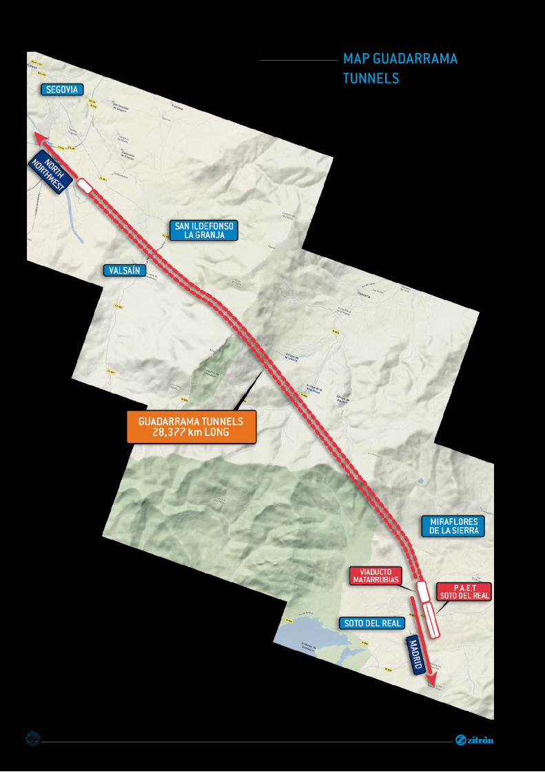
MAP GUADARRAMA TUNNELS
THE TUNNELS IN GUADARRAMA FOR THE HIGH SPEED RAILWAY
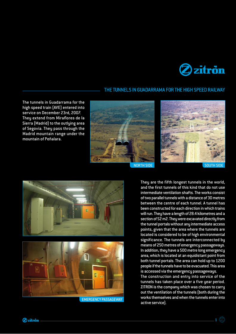
The tunnels in Guadarrama for the high speed train (AVE) entered into service on December 23rd, 2007. They extend from Miraflores de la Sierra (Madrid) to the outlying area of Segovia. They pass through the Madrid mountain range under the mountain of Peñalara.
They are the fifth longest tunnels in the world, and the first tunnels of this kind that do not use intermediate ventilation shafts. The works consist of two parallel tunnels with a distance of 30 metres between the centre of each tunnel. A tunnel has been constructed for each direction in which trains will run. They have a length of 28.4 kilometres and a section of 52 m2. They were excavated directly from the tunnel portals without any intermediate access points, given that the area where the tunnels are located is considered to be of high environmental significance. The tunnels are interconnected by means of 250 metres of emergency passageways. In addition, they have a 500 metre long emergency area, which is located at an equidistant point from both tunnel portals. The area can hold up to 1200 people if the tunnels have to be evacuated. This area is accessed via the emergency passageways. The construction and entry into service of the tunnels has taken place over a five year period. ZITRON is the company which was chosen to carry out the ventilation of the tunnels (both during the works themselves and when the tunnels enter into active service).
NORTH SIDE SOUTH SIDE
EMERGENCY PASSAGEWAY
1

Ventilation during cons tr uc tion was an important challenge, as the project involved one of the longest blind tunnel ever to be ventilated – approximately 15 kilometres in length. The system functioned by the entry of fresh air through tubes driven by several fans to the work face. The polluted air was then displaced to the exterior through the tunnel itself. This was necessary as a human team had to work in the tunnel’s interior to create the internal infrastructure of the tunnel. This team was continuously exposed to harmful and hazardous gases from equipment and machines, and had to receive fresh air in order to ensure that working conditions were safe. In accordance with the particular characteristics of each mouth, the following fans were used during the tunnel works: NORTHERN PORTAL: 2 x ZVN 1-20-450/4 (One for each tunnel)
SOUTHERN PORTAL: 3 x ZVN 1-18-315/4 (One for each tunnel)
NORTH SIDE
SOUTH SIDE
SOUTH SIDE
RAILWAY HIGHSPEED TUNNEL
28 km
Initially, the definitive ventilation system planned for these tunnels was ventilation by means of two main stations located at the tunnel ends, with closing doors at the tunnel entrances in order to pressurise one of the tunnels. However, after having studied the problems associated with a possible failure in the opening and closing of the doors with a high speed train in the tunnel, the decision was made to carry out a new study of the ventilation system in order to replace the tunnel doors with a pneumatic closure system using jets of air, thus ensuring that the ventilation system proposed in the project would function correctly. The solution for the definitive ventilation of the Guadarrama tunnels was reached using CFD (Computational Fluid Dynamics). This technique was used to perform multiple simulations in order to determine the most suitable ventilation system for a railway tunnel of this length (28.5 Km without intermediate ventilation shafts).
VENTILATION DURING CONSTRUCTION
VENTILATION DURING OPERATION
NORTH SIDE
2
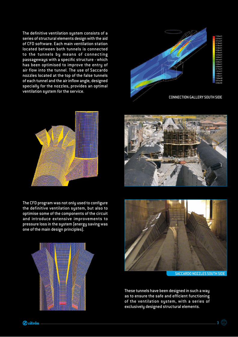
CONNECTION GALLERY SOUTH SIDE
The definitive ventilation system consists of a series of structural elements design with the aid of CFD software. Each main ventilation station located between both tunnels is connected to the tunnels by means of connec ting passageways with a specific structure - which has been optimised to improve the entry of air flow into the tunnel. The use of Saccardo nozzles located at the top of the false tunnels of each tunnel and the air inflow angle, designed specially for the nozzles, provides an optimal ventilation system for the service.
The CFD program was not only used to configure the definitive ventilation system, but also to optimise some of the components of the circuit and introduce extensive improvements to pressure loss in the system (energy saving was one of the main design principles).
These tunnels have been designed in such a way as to ensure the safe and efficient functioning of the ventilation system, with a series of exclusively designed structural elements.
SACCARDO NOZZLES SOUTH SIDE
3
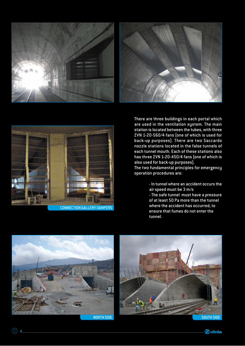
There are three buildings in each portal which are used in the ventilation system. The main station is located between the tubes, with three ZVN 1-20-560/4 fans (one of which is used for back-up purposes). There are two Saccardo nozzle stations located in the false tunnels of each tunnel mouth. Each of these stations also has three ZVN 1-20-450/4 fans (one of which is also used for back-up purposes).The two fundamental principles for emergency operation procedures are:
- In tunnel where an accident occurs the air speed must be 3 m/s - The safe tunnel must have a pressure of at least 50 Pa more than the tunnel where the accident has occurred, to ensure that fumes do not enter the tunnel.
CONNECTION GALLERY DAMPERS
NORTH SIDE SOUTH SIDE
4

The following operational modes will apply in case of emergency:
This operational mode is applied in the tunnel where the accident occurred, especially if the accident results in the emission of fumes. The main ventilation station, which is chosen according to the protocol established by the control centre, will start to administer a specific air flow generated by two fans (with a third fan for back-up purposes). At the same time another two fans in the Saccardo nozzle
station at the same end of the tunnel will provide further air flow (with a third fan for back-up purposes). The air flow in the tunnel will thus reach a speed of 3 m/s.The other fans in this tunnel will not be used. All of the numeric values and the duty point of the fans were obtained through several CFD simulations.
VENTILATION MODE
PRESSURIZATION MODE
This procedure is used in the safe tube, which the train passengers will access through the emergency passageways. The main ventilation station, which is not providing air for the tunnel where the accident occurred, is used. This station will provide a flow of air using two fans (with a third fan in back-up mode). At the same time another two fans in the Saccardo nozzle station at the same end of the tunnel will provide further air flow (with a third fan for back-up purposes). Two fans in the Saccardo nozzle station at the opposite end of the tunnel will provide further air flow (with a third fan for back-up purposes).
5

The natural draught in the tunnel was also checked in situ to see how it affects the air speed in the tunnel’s interior (this is an important consideration for the control centre when deciding which stations will be employed during an emergency). The tests confirmed - and even exceeded- the designed performance expectations. Without any doubt, the GUADARRAMA tunnels also represent a milestone in emergency ventilation systems.
Before the off icial opening of the tunnel, ventilation tests were performed to check the validity of the system designed using the CFD software. During the general tests, the air speed was measured in the tunnel (which must be 3 m/s or greater when the emergency system is operating in a tunnel where an accident has occurred). These measurements were made using anemometers located in several sections of the tunnel close to both ends of the tunnel. In emergency situations, the other tunnel (safe tube) must have an overpressure of 50 Pa more than the tunnel where the accident occurred. This was checked during final tests.
TESTS
By doing this, we obtain an over pressurization of approximately 50 Pa in this tube at any point, compared to the damaged tube. The ventilation system for the Guadarrama tunnels, designed and manufactured by ZITRON are an important innovation for long railway tunnels, as intermediate ventilation shafts are not used and the ventilation system operates from the tunnel mouths. This system is not only used in emergency situations (for which it has been designed), but also also when the TALGO train passes through the tunnel each day or when maintenance works are carried out in the interior of the tunnel and fresh air has to be provided for the workers.
MAIN STATION FAN ZVN 1-20-560/4
6
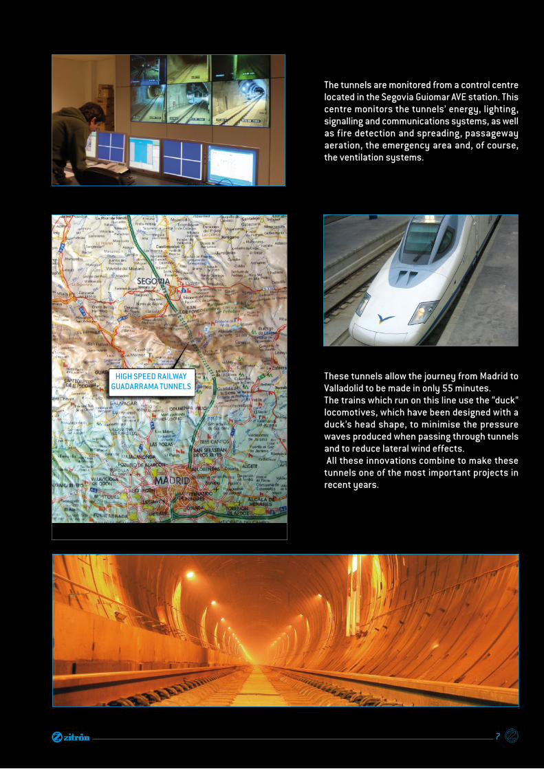
The tunnels are monitored from a control centre located in the Segovia Guiomar AVE station. This centre monitors the tunnels’ energy, lighting, signalling and communications systems, as well as fire detection and spreading, passageway aeration, the emergency area and, of course, the ventilation systems.
These tunnels allow the journey from Madrid to Valladolid to be made in only 55 minutes.The trains which run on this line use the “duck” locomotives, which have been designed with a duck’s head shape, to minimise the pressure waves produced when passing through tunnels and to reduce lateral wind effects. All these innovations combine to make these tunnels one of the most important projects in recent years.
HIGH SPEED RAILWAY GUADARRAMA TUNNELS
7

ZITRON’S TEST BENCH
Pitot tubestesting fan
test benchjet fans
8

settling means nozzles settling means auxiliary fan silencer

HEAD OFFICEAutovía AS II. nº 2386Polígono de Roces33211 Gijón (Asturias) Spain+34 985 168 [email protected]
www.zitron.com