The tubes have design maximum By - americanradiohistory.com · The TC-75, a compact 15 -watt 3 ......
8
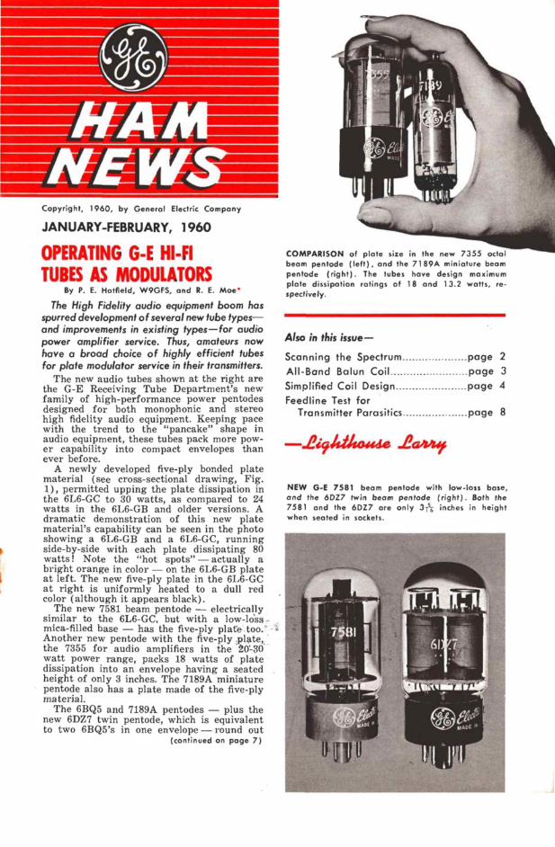
AtE W - Copyright, 1960, by General Electric Company JANUARY -FEBRUARY, 1960 OPERATING G -E HI-FI TUBES AS MODULATORS By P. E. Hatfield, W9GFS, and R. E. Moe The High Fidelity audio equipment boom has spurred development of several new tube types- and improvements in existing types-for audio power amplifier service. Thus, amateurs now have a broad choice of highly efficient tubes for plate modulator service in their transmitters. The new audio tubes shown at the right are the G -E Receiving Tube Department's new family of high-performance power pentodes designed for both monophonic and stereo high fidelity audio equipment. Keeping pace with the trend to the "pancake" shape in audio equipment, these tubes pack more pow- er capability into compact envelopes than ever before. A newly developed five-ply bonded plate material (see cross-sectional drawing, Fig. 1), permitted upping the plate dissipation in the 6L6-GC to 30 watts, as compared to 24 watts in the 6L6-GB and older versions. A dramatic demonstration of this new plate material's capability can be seen in the photo showing a 6L6 -GB and a 6L6 -GC, running side -by -side with each plate dissipating 80 watts! Note the "hot spots" - actually a bright orange in color - on the 6L6 -GB plate at left. The new five-ply plate in the 6L6 -GC at right is uniformly heated to a dull red color (although it appears black). The new 7581 beam pentode - electrically similar to the 6L6 -GC, but with a low -loss - mica -filled base - has the five-ply plate too." Another new pentode with the five-ply plate, the 7355 for audio amplifiers in the 20'--30 watt power range, packs 18 watts of plate dissipation into an envelope having a seated height of only 3 inches. The 7189A miniature pentode also has a plate made of the five-ply material. The 6BQ5 and 7189A pentodes - plus the new 6DZ7 twin pentode, which is equivalent to two 6BQ5's in one envelope - round out (continued on page 7) COMPARISON of plate size in the new 7355 octal beam pentode (left), and the 7189A miniature beam pentode (right). The tubes have design maximum plate dissipation ratings of 18 and 13.2 watts, re- spectively. Also in this issue- Scanning the Spectrum page 2 All -Band Balun Coil page 3 Simplified Coil Design page 4 Feedline Test for Transmitter Parasitics page 8 2i914o4 de .La' NEW G -E 7581 beam pentode with low -loss base, and the 6DZ7 twin beam pentode (right). Both the 7581 and the 6DZ7 are only 375-y inches in height when seated in sockets. 1 -7 ,11 I . WADI 1} u - ~if?' .y MAD(
Transcript of The tubes have design maximum By - americanradiohistory.com · The TC-75, a compact 15 -watt 3 ......
AtE W - Copyright, 1960, by General Electric Company
JANUARY -FEBRUARY, 1960
OPERATING G -E HI-FI
TUBES AS MODULATORS By P. E. Hatfield, W9GFS, and R. E. Moe
The High Fidelity audio equipment boom has spurred development of several new tube types- and improvements in existing types-for audio power amplifier service. Thus, amateurs now have a broad choice of highly efficient tubes for plate modulator service in their transmitters.
The new audio tubes shown at the right are the G -E Receiving Tube Department's new family of high-performance power pentodes designed for both monophonic and stereo high fidelity audio equipment. Keeping pace with the trend to the "pancake" shape in audio equipment, these tubes pack more pow- er capability into compact envelopes than ever before.
A newly developed five-ply bonded plate material (see cross-sectional drawing, Fig. 1), permitted upping the plate dissipation in the 6L6 -GC to 30 watts, as compared to 24 watts in the 6L6 -GB and older versions. A dramatic demonstration of this new plate material's capability can be seen in the photo showing a 6L6 -GB and a 6L6 -GC, running side -by -side with each plate dissipating 80 watts! Note the "hot spots" - actually a bright orange in color - on the 6L6 -GB plate at left. The new five-ply plate in the 6L6 -GC at right is uniformly heated to a dull red color (although it appears black).
The new 7581 beam pentode - electrically similar to the 6L6 -GC, but with a low -loss - mica -filled base - has the five-ply plate too." Another new pentode with the five-ply plate, the 7355 for audio amplifiers in the 20'--30 watt power range, packs 18 watts of plate dissipation into an envelope having a seated height of only 3 inches. The 7189A miniature pentode also has a plate made of the five-ply material.
The 6BQ5 and 7189A pentodes - plus the new 6DZ7 twin pentode, which is equivalent to two 6BQ5's in one envelope - round out
(continued on page 7)
COMPARISON of plate size in the new 7355 octal beam pentode (left), and the 7189A miniature beam pentode (right). The tubes have design maximum plate dissipation ratings of 18 and 13.2 watts, re- spectively.
Also in this issue-
Scanning the Spectrum page 2
All -Band Balun Coil page 3
Simplified Coil Design page 4
Feedline Test for Transmitter Parasitics page 8
2i914o4 de .La' NEW G -E 7581 beam pentode with low -loss base, and the 6DZ7 twin beam pentode (right). Both the 7581 and the 6DZ7 are only 375-y inches in height when seated in sockets.
1
-7 ,11 I .
WADI
1} u
- ~if?' .y
MAD(

NEE
~WI Me
rfferkou
1 --g-
. i
1 y[,'''!r'rJnnAs9\
COMING NEXT ISSUE . . . The TC-75, a compact 15 -watt 3.8 to 4.0 -
megacycle mobile transmitter/converter (tucked under the dash of the author's car, above) will be described by W4QVL. This rig is only 3 inches high, 7 inches wide and 5 inches deep. It has five tubes and, with a modern external power supply, draws only 3 amperes from a 12 -volt auto electrical sys- tem. Don't miss this issue, which also will announce the recipient of General Electric's 1959 Edison Radio Amateur Award for out- standing public service,
G.E.'s LME DEPARTMENT . . .
WA2ANU, K2HLT and W2OIQ, three of the authors in this issue, all hail from Gen- eral Electric's Light Military Electronics Department, with headquarters in Utica, New York. This department designs and builds an impressive variety of electronic equipment for the U.S. military services.
Included in their products are armament and control systems, radar, counter-measures, communications and navigational equipment for airborne weapons. We can't go into more details here, except to say that this depart- ment also participated in the development of the synchronous communications system, better known as double sideband, and now used by many radio amateurs.
NOTE: The disclosure of any information or arrangements herein conveys no license under any patents of General Electric Company or others. In the absence of an express written agreement to the contrary, the General Electric Com- pany assumes no liability for patent infringement (or any other liability) arising from the use of such information by others.
2.
CLUB BULLETINS WANTED . . .
Among the many amateur radio club news- papers and bulletins which arrive regularly at the G -E HAM NEWS office, we notice some which are statewide, or section -wide in coverage. They include: Florida Skip; Vir- ginia Ham Bulletin, and The Bison, from Indiana.
This is an excellent means of communicat- ing news of interest to all radio amateurs in a state and, personally, I'd like to see more such bulletins published. I receive a number of newspapers from clubs in exchange for G -E HAM NEWS. Welcome them from clubs who may not now be sending them to me.
BRAILLE TECHNICAL PRESS ON RECORDS . . .
A "Talking Book" edition of the only radio and electronics magazine for the sightless radio amateur, hi-fi enthusiast, sound record- ing technician, radio and TV serviceman, is now available. This edition started with the September, 1959 issue, in celebration of the magazine's tenth anniversary.
I listened to the September record and could easily draw a schematic diagram from the oral description. Write to the editor, Bob Gunderson, W2JIO, at 984 Waring Avenue, New York 69, N. Y., for details.
Bob, incidentally, was the recipient of Gen- eral Electric's 1955 Edison Radio Amateur Award for outstanding public service. He de- veloped 30 types of auditory test instruments which opened the electronics field to the blind.
ADDRESS YOUR QSL's . . .
Make sure you fully address all QSL cards - operator's name, number and street, city, zone and state - you mail to other radio amateurs. Don't just address them "Amateur Radio W4 , Operator Joe, Anytown, Ky.," or those QSL's may wind up in the "dead letter" file. In some post offices, there happen to be radio amateurs sorting mail, and they may watch for poorly addressed QSL cards for amateurs they know, but don't count on it!
We understand that some amateurs file a change of address form with their local post office, giving just their call letters and city as the old address, and their house number, street and city as the new address. This helps delivery of incoming QSL cards with insuffi- cient addresses to you.
NEW ADDRESS FOR G -E HAM NEWS In case you haven't noticed, our back -page
sign -off on the last few issues has been changed from Schenectady, New York, to the headquarters of General Electric's Receiving Tube Department in Owensboro, Kentucky. Please address your communications to G -E HAM NEWS down heah, suh.
-.244,Madikse 2a/840, (Colonel, that is)

ALL -BAND BALUN COIL By Carl Byler - K2HLT
Recently the writer was faced with two problems:
1. Matching the pi -network (unbalanced) out- put of a transmitter to a doublet (balanced) antenna.
2. Limited finances.
After considerable design work and testing, the All -Band Balun Coil was found to be the answer to the first problem without aggravating the second problem.
THE FEEDLINE BALANCING PROBLEM is common to many radio amateurs since the pi - network is widely employed in transmitters. It has several advantages, among them being low harmonic output to prevent interference to nearby television receivers.
Also, balanced antennas - half wave di- pole (doublet), Yagi beams with split driven element, horizontal trap antenna, etc. - are very popular. Since 72 ohm transmitting twin -lead is available at a lower price than coaxial cable - especially the RG11/U type - the balun was built into the transmitter and 72 ohm twin -lead connected from the transmitter to the antenna. The placement is not critical; the balun could easily be located some distance from the transmitter and fed with a coaxial cable (but this defeats our original purpose).
This balun represents a simple autotrans- former, tuned to resonance at approximately 14 megacycles by the distributed capacitance of the coaxial cable in the top half of the coil. The Q of the resonant circuit is approximate- ly 200 (hence the low loss). When loaded with
K2HLT is an engineer with the Light Military Elec- tronics Deportment, General Electric Co., Utica, N. Y.
FIG. 1. SCHEMATIC DIA- GRAM and constructional details of the balun coil. One side of the 72 -ohm balanced output connects to the shield on the coaxial cable in the upper coil; the other side connects to the center conductor. Inner and outer conductors of the coaxial cable in the lower coil are connected together at each end, and grounded at the bottom end.
¡ ` i Q
( 1 .
I t;. .
I t(` %
i" .
,á!
THE ALL -BAND BALUN made from RG-59A/U coaxial cable. The coil "form" is a sheet of laminated in- sulating board (G.E. Textolite) 15 x 9 x `/e of an inch thick. Two rows of 19 holes each are drilled on 3/6 -inch centers, with the rows 6 inches apart. A short length of 72 -ohm kilowatt twinlead runs to the antenna feedline from the terminal posts at the center of the board. Small angle brackets fasten the balun coil into the transmitter cabinet.
a 72 ohm load, the selectivity of the tuned circuit is broadened out to approximately a 30 -megacycle bandpass. The transmitter sig- nal is coupled, via the coaxial cable of the top half of the coil, to the bottom half, which is simply a coil to ground. However, this bot- tom coil is inductively coupled to the top coil (with essentially unity coupling). Each. coil feeds one side of the balanced output. Since each half of the coil has equal inductance, the output will be balanced.
CONSTRUCTIONAL DETAILS for the balun coil are shown in Fig. 1 and the side view photo. The phenolic board is drilled for the cable, chassis type coaxial cable connector (SO -239) and terminal posts. The coaxial cable for each coil is threaded through the holes and then soldered connections are made. Approximately 30 feet of RG-59/U cable are required for the balun illustrated.
The RG-59A/U coaxial cable used hap- pened to be available. Actually, the attenua- tion would be slightly less with a larger coaxial cable; also the maximum voltage rat -
(continued on page 6)
CND.
HOLES DRILLE
FOR COAXIAL CABLE
COAXIAL CONNECTOR
72 OHM UNBALANCED
INPUT
TO 72'OHM TWIN LEAD
1/B' PHENOLIC BOARD
41111115.»
1.6TO30MC. ATTEN. <S DEL NBALANCE <5DB kS.W.R.< 1.2
HM BALANCED
(TWIN -LEAD) OUTPUT
RG- 59A/U 19 TURNS C.T. SPACED 1,2 TURN 6' DIA.
3

SIMPLIFIED COIL DESIGN (Part I) By B. H. Baldridge, W20IQ
PROBLEM - HOW TO WIND COILS accurately for specific amateur radio applica- tions. Solutions:
1. Calculating the coil inductance and di- mensions from the formula
'2 is
Lo - 2.54 x 0.039481 d / n'K 1 - too complicated; forget it.
2. Estimating inductance with reactance charts, plus a coil nomograph. Usually after winding, finished coil must be pruned to the correct inductance value to compensate for inaccuracies.
3. Simplified graphs which can be pre- pared with equipment found in most amateur radio stations.
Solution 3 takes the "try" out of "cut and try" coil winding. The materials needed are: 1) Log graph paper (K & E No. 359 - 110, log 2 x 2 cycles, or equivalent) ; 2) calibrated receiver; 3) two -terminal oscillator (see Fig. 1 for a Franklin oscillator circuit) ; and 4) at least two calibrated fixed capacitors in the range of 20 and 150 mmf. Access to a "Q" meter will permit all of the measure- ments to be made with no additional equip- ment; or, a calibrated grid -dip oscillator will take the place of the calibrated receiver and two -terminal oscillator.
Suppose a coil 1 inch in diameter and 1% inches long, having 30 turns, is available; and our standard capacitors are C81 = 19 mmf, and C8 = 160 mmf. Connecting the
W20IQ is a consulting engineer in the Communica- tion and Navigation section of General Electric's Light Military Electronics Department, Utica, N. Y.
FIG. 1. SCHEMATIC DIAGRAM of a Franklin oscil- lator with which the measurements outlined in the text may be made. All resistances are in ohms, all capacitances are in mmf, unless otherwise specified. Capacitances C. and C, should be as small as will permit maintenance of oscillations, usually 1 or 2
mmf each. Values for C. are given in the text.
coil to the Franklin oscillator, we can find the resonant frequency by locating the fre- quency of oscillation. If, with C8, across the coil, the oscillation frequency is measured at say 9 megacycles; with C8, across the coil it would be 3.5 megacycles. This information could also be obtained by connecting the coil to a "Q" meter; or measuring resonance of the coil across the test capacitors with the grid -dip oscillator.
Plot this information on log -log graph paper and connect the two points with a straight line, as shown in Fig. 2. Note that to tune from 3.5 to 4 megacycles requires an approximate capacitance variation from 162 to 121 mmf, or a spread of 41 mmf. A total fixed, distributed and tuning condenser mini- mum capacitance of 121 mmf, and a variable capacitance of 41 mmf would spread the 3.5 -
(continued on page 6)
;°° 1 1 f 100 C I' DIÁYEIER -
LL I f' LEY6 rY '00
100
80
60
50
40
30
20
10 2 3 4 5 6 8 10 20
FREQUENCY IN MEGACYCLES
30 40
4
FIG. 2. GRAPH PLOTTED on log paper for a coil, 1 inch in diameter and 11/2
inches long, with 30 turns equally spaced. The tuning range with a 140-mmf var- iable capacitor is approximately from 3.5 to 9 megacycles.
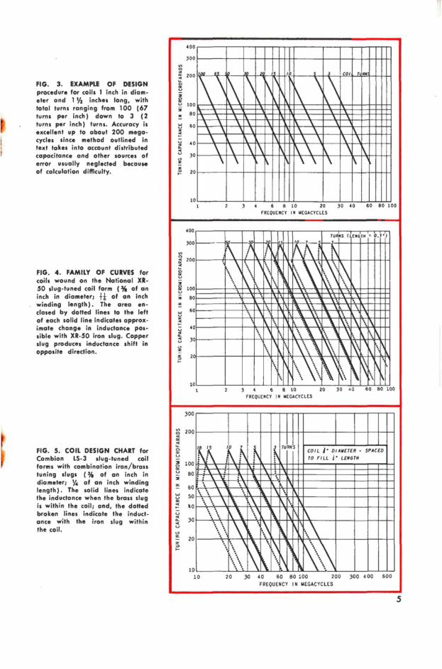
FIG. 3. EXAMPLE OF DESIGN procedure for coils 1 inch in diam- eter and 17/2 inches long, with total turns ranging from 100 (67 turns per inch) down to 3 (2 turns per inch) turns. Accuracy is excellent up to about 200 mega- cycles since method outlined in text takes into account distributed capacitance and other sources of error usually neglected because of calculation difficulty.
FIG. 4. FAMILY OF CURVES for coils wound on the National XR- 50 slug -tuned coil form (% of an inch in diameter; +} of an inch winding length). The area en- closed by dotted lines to the left of each solid line indicates approx- imate change in inductance pos- sible with XR-50 iron slug. Copper slug produces inductance shift in opposite direction.
FIG. 5. COIL DESIGN CHART for Cambion LS -3 slug -tuned coil forms with combination iron/brass tuning slugs (% of an inch in diameter; '/4 of an inch winding length). The solid lines indicate the inductance when the brass slug is within the coil; and, the dotted broken lines indicate the induct- ance with the iron slug within the coil.
400
i 200
u
100
uuiiui- Ii!iiUIIIIII ,1 ,
[Ol Mill
._ ~~~-\m~amf.mmowsw 60
'
.i11.a,..ii 1 1 'I1 30
7 20
10
2 3 4 6
FREQUENCY
8 10
IN
20 30 40 60
MEGACYCLES
80 100
400 1 (NM ' 0.7'1
300
200 ILliiknainTURNS :
S00 , 'p L`1,11 a IMIBI_\qM ATFV \` 9\~11121\~1~11 i 80 MK" NIMI\\pM1~~1~"e11"g amlme\itramHa\omm - ~IIMIIIIK111111"gÉ_\®IM u
60 _,, ̀FQqKI',1 40
.,.a`i`L-\yy-,A,,1 Ú 30
? Eli ,®®, 1 20
F 10 III , '
1 2 3 4 6 8 10 20 30 40 60
FREQUENCY IN MEGACYCLES
80 100
300
ó 200 I11111--I11 á _-., z u 1001Ma_WiM1á\i\W\ig
!g 15 0
: : COIL )' DIAMETER - SPACED
TO FILL i' LENGTH
& ~MOM u B0 if>Ra_lJmmkaa\ \m ~~~ma i MUJlll\K\IIW \fi ~I~MM z B0 `,.a al ~=1111111Z
50
so
`c,,, RI-_- ,,(1,--E Ú 30 _?.'11
10 ht, ' 10 20 30 40 60 80 100 200 300 400 600
FREQUENCY IN MEGACYCLES
5
SIMPLIFIED COIL DESIGN (continued from page 4) megacycle band over 180° shaft rotation. The same coil will tune from 7.0 to 7.3 megacycles with an approximate capacity variation from 36.5 to 33.5 mmf, or a spread of 3 mmf. A total fixed, distributed and tuning condenser minimum capacitance of 33.5 mmf and a 3- mmf variable would spread the 7 -megacycle band over 180° shaft rotation. If the dis- tribtued and input capacity add up to 12 mmf, a 150-mmf variable will tune both the 3.5 and 7 -megacycle bands. A parallel 50 mmf variable and a fixed 100 mmf capacitor would make it impossible to tune the circuit to 7 megacycles, and the use of a 50 mmf variable alone would prevent inadvertent tuning to 3.5 megacycles in lieu of 7 mega- cycles. If the total input, output, and dis- tributed C equals 15 mmf, the coil will tune to 10.5 megacycles and will drive a doubler to 21 megacycles.
The system can be further expanded by plotting coils with different parameters as shown in Fig. 3, which illustrates a typical family of curves for coils 1 inch in diam- eter and 11/2 inches long.
Graphs for each individual coil of given number of turns are constructed as described. Note that the spacing between the graphs for the coils is proportional to the log of the num- ber of turns. A slight slope change and bend- ing of the individual coil plots is noted as the frequency approaches the natural res- onant frequency of the tuning element, due to the increased proportional effect of the distributed capacitance, coil leads and ter- minals, and other factors impossible to elimi- nate and difficult to calculate in practical coil problems. These factors are usually neglected on impedance charts, making the charts use- less for practical applications requiring ac- curate construction of small inductances.
Precise determination of coil parameters can be obtained by limiting the use of a given chart to a 10 -to -1 turns ratio when determin- ing coil parameters from data taken with coils of a few turns. Figs. 4 and 5 show a similar family of curves for widely used com- mercial coil forms. The inductance variation made possible by positioning the slugs is il- lustrated by the dashed lines.
A useful chart for clipping coils such as B & W Miniductors can be made from a couple of assorted lengths of the size in ques- tion. The fact that length and number of turns are changed simultaneously does not void the chart; the slope remains the same but the spacing between graphs of the coils will be slightly changed.
Any number of similar charts may be rap- idly prepared. From two or more experi- mentally plotted graphs of individual ele- ments approximately within the desired range, a family of curves may be drawn to permit accurate selection of the desired tun- ing elements. Frequency doublers or power amplifiers thus may be accurately ganged.
6
Note that for a small increment of fre- quency, such as a typical amateur band, the use of fixed capacitors to set the operating point and a small variable straight line ca- pacitance will give essentially straight line frequency tuning. The ganging of circuits with straight line tuning is no problem. As charts for progressively larger power coils or doubler coils all have the same slope, the choice of capacitors and inductors to gang and track tuned circuits becomes elementary.
(Part II will appear in a subsequent issue - Ed.)
ALL -BAND BALUN COIL (continued from page 3)
ing (2300 volts for RG-59A./U) would be higher. However, the loss in this model is negligible and the voltage is low (under 1300 volts peak to peak for a one -kilowatt ampli- tude modulated transmitter) as long as the balun is kept loaded.
Other 72 ohm coaxial cables, such as RG- 8/U, RG 11/U, RG-12/U, RG-13/U, RG-15/U, RG-34/U, and RG-35/U may be used in a balun of this type. The coil usually must be redesigned to compensate for the different characteristics of the cable, such as the out- side diameter. The procedure in this case would be to adjust the length and size of the coil to resonate at 14 megacycles, while main- taining the required bandwidth under loaded conditions.
This balun was tested with both low level (signal generator) and high level (pair of 813's plate modulated by a pair of 813's) signals. From 1.8 through 30 megacycles, the voltage standing wave ratio (V.S.W.R.) was measured to be less than 1.2:1. The unbal- ance and insertion loss were measured and found to be less than 0.5 decibels.
The balance was checked with high power by attaching two 200 -watt light bulbs - one on each side of the 72 ohm balanced line to ground. The transmitter lighted both bulbs equally to full brilliance with less than 500 watts DC input to the 813's.
As proof of the pudding, the writer fin- nished and installed the assembly about 10 o'clock on a Friday night. After loading the transmitter through the balun into a simple doublet antenna, he called "CQ" on the crowd- ed 14 -megacycle phone band. Before retiring at 11 o'clock, numerous QSO's were completed, with the weakest signal report received being 10 db over S9 from San Francisco.
HOW TO GET G -E HAM NEWS . .
G -E HAM NEWS is available free of charge if you pick it up from your local G -E Tube distributor. Some distributors mail copies local- ly to their customers. Or, for those who pre- fer receiving copies directly from us, we have a low-cost subscription plan at $1.00 per year. Order your subscription from: G -E HAM NEWS, General Electric Company, Receiving Tube Department, 316 E. Ninth Street, Owens- boro, Kentucky, U.S.A.

OPERATING G -E HI-FI TUBES AS MODULATORS (continued from page 1)
this hi-fi tube family. These tubes normally are rated in the technical data for push-pull class AB, operation at low harmonic distor- tion - about 2 percent - in high fidelity amplifier service. These ratings are given in the "Hi -Fi Service" columns in Table I.
Plate modulator service in amateur trans- mitters, however, usually permits the audio power tubes to be operated with higher dis- tortion - up to about 10 percent - in the output. This allows the modulator tubes to be driven harder - up to the maximum ratings - with a resultant 25 to 90 -percent increase in power output, depending on tube type.
A session with the "OPERATION CHAR- ACTERISTICS" curves on the DESCRIP- TION AND RATING sheets for these tubes resulted in the figures listed in the "Modu- lator Service" columns in Table I. These operating conditions are all within the "MAXIMUM RATINGS" listings for each tube type. A typical class AB, amplifier cir- cuit is used to obtain this data.
A 24 -watt modulator with a single tube output stage can be built around a 6DZ7 twin pentode, operated with 400 volts on the plates. Or, a pair of 6BQ5's can be substituted if desired. For high power output at a mod- erate 400 plate volts, a pair of 7355's will de- liver 54 watts of audio power. These figures do not include output transformer losses.
Plan your new plate modulator around the above tubes. As makers of high fidelity equip- ment can verify, they really deliver the watts, and with low distortion too.
' W9GFS is an engineer in the Technical Data Unit, and R. E. Moe is the Manager of Engineering in General Electric's Receiving Tube Department, Owensboro, Ky.
r o l
t
1 1 -i s-~ 11 ~ 11
a
p, .~t1a.
UNRETOUCHED PHOTO showing a 616 -GB (left) and a new 616 -GC (right) with five-ply bonded plate material, each operating at a plate dissipation of 80 watts. The 616 -GB has "hot spots" on the plate, bright orange in color, while the plate of the 616 -GC shows only a uniform dull red, due to the superior heat dissipating characteristics of the new material.
FIG. 1. CROSS-SECTIONAL VIEW of G. E.'s new five- ply bonded plate material. The metal "sandwich" gives better heat conduction and radiation than conventional single -layer anode materials.
TABLE I - COMPARISON OF HI-FI AND MODULATOR SERVICE
PUSH-PULL CLASS AB, AMPLIFIER, VALUES FOR TWO TUBES
TUBE TYPE 1 - 6DZ7 2 - 6B05 2 - 7189A
2 - 6L6 -GC 2 - 7581
2 - 7355
Hi -FI Mod. Hi -Fi Mod. Hi -Fi Mod. Rating Rating Rating Rating Rating Rating
Plate Voltage 400 400 450 450 300 400 Volts Screen Voltage 250 250 400 400 250 300 Volts Grid -Number 1 Voltage -11 -11 -37 -37 -21 -32 Volts Peak AF Grid -Number 1 Voltage 22 26.4 70 85 42 70 Volts Zero -Signal Plate Current 80 80 116 116 100 72 Milliamperes Maximum -Signal Plate Current 100 110 210 240 185 244 Milliamperes Zero -Signal Screen Current 4.0 4.0 5.6 5.6 5.5 4.6 Milliamperes Maximum -Signal Screen Current 13 16 22 30 24 30.4 Milliamperes Effective Laad Resistance, Plate -ta -Plate 9000 9000 5600 5600 4000 3500 Ohms Total Harmanic Distortions 2.5 5 1.8 7 2.0 5.8 Percent Maximum -Signal Pawer Outputs 18 24 55 70 28.5 54 Watts
'Without feedback. 'Power output figures quoted do not include losses in output transformers usually encountered in practical circuits.
7
A FEEDLINE TEST FOR TRANSMITTER PARASITICS By D. T. Geiser - WA2ANU
iT
DUMMY
LOAD
BUILD -IT -YOURSELF IDEAS from the 999 radio amateurs at
GENERAL ELECTRIC
published bi-monthly by RECEIVING TUBE DEPARTMENT
Owensboro, Ky.
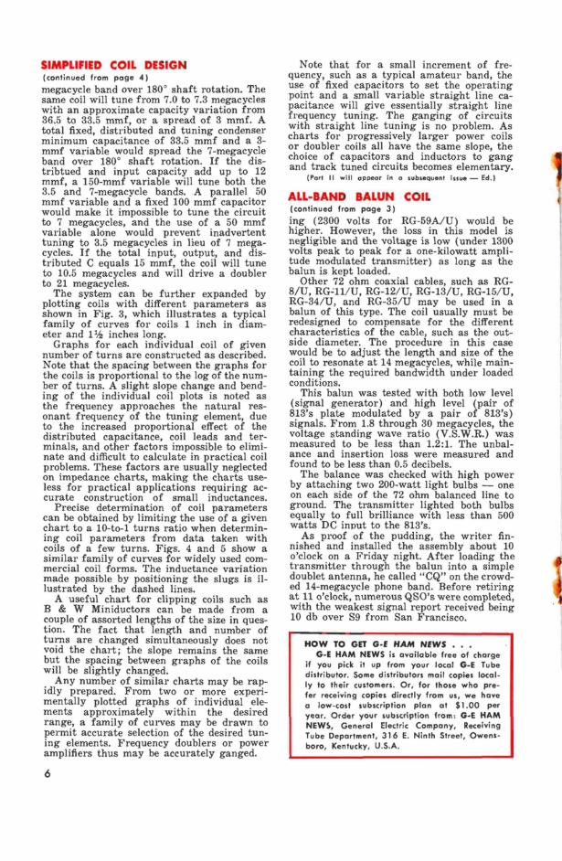
TRANSMITTERS that are stable under CW or no -modulation conditions sometimes break into parasitic oscillation or other instability when amplitude modulated. The test de- scribed here has proved useful in checking for instability during modulation peaks.
Ideally, transmitters should be tested feed- ing dummy loads before on -the -air operation. If such a test is made, one simple additional test permits a simultaneous check for para- sitics. This modification consists of shunting the dummy load with a parallel -tuned circuit. If tuned to the operating frequency and hav- ing a moderate Q, the added circuit is elec- trically invisible at the desired frequency but very much in evidence at other frequencies.
Thus a standing wave ratio (SWR) bridge will indicate a normal standing wave
ratio if only a pure modulated output wave is present. If parasitics or off -frequency os- cillation occurs during modulation, the SWR meter will kick because the tuned circuit (L -C) is not resonant at other frequencies. The test circuit used successfully at WA2- ANU is shown, Fig. 1.
If an antenna system is matched to a low standing wave ratio and resonant, the SWR meter by itself may be used to show the pres- ence of spurious output on the feedline.
This test is mainly useful to check massive errors and should not be considered a valid check for very low power parasitics and har- monics.
WA2ANU is a components engineer with General Electric's Light Military Electronics Department, Utica, N. Y.
FIG. ;11. BLOCK DIAGRAM of parasitic test circuit. Tuned circuit L/C is tuned to the operating frequency. Capacitor C should be about 5 mmf meter SWR per (400 mmf for 80 meters; 40 mmf for TRANSMITTER
METER Co)-
10 meters). Off -frequency emissions are shown up by an indication of reflected power on the SWR meter.
JANUARY -FEBRUARY, 1 9 6 0
HAM NEWS
Available FREE from your G -E Tube Distributor
VOL. 15 - NO. 1
E. A. Neal, W4ITC - Editor
DesROEIE R TS


![Dell 2130cn - ServiceMan [2010]](https://static.fdocuments.us/doc/165x107/55cf9c88550346d033aa2576/dell-2130cn-serviceman-2010.jpg)