
The thin concrete shells of Jack Christiansen - UPV · Proceedings of the International Association...
12
Proceedings of the International Association for Shell and Spatial Structures (IASS) Symposium 2009, Valencia Evolution and Trends in Design, Analysis and Construction of Shell and Spatial Structures 28 September – 2 October 2009, Universidad Politecnica de Valencia, Spain Alberto DOMINGO and Carlos LAZARO (eds.) The thin concrete shells of Jack Christiansen Edward SEGAL * * Structural engineer, Simpson Gumpertz & Heger 19 West 34 th Street, Suite 1000, New York, NY 10034 [email protected] Abstract This paper (Segal [8]) discusses Jack Christiansen’s design and construction ideas for thin concrete shells and how they translated into specific structures like his hexagonal umbrellas at Seattle’s Worlds Fair (1962) and the Bainbridge Island Grandstand (1990) on Bainbridge Island, Washington. Additionally, this paper suggests how Christiansen’s ideas can be applied today to generate and build new shell forms. Keywords: Jack Christiansen, thin concrete shell, hyperbolic paraboloid, formwork 1. Introduction Jack Christiansen (Figure 1), best known for the Seattle Kingdome, designed thin concrete shells in a variety of forms, including barrels and hyperbolic paraboloid umbrellas, across a wide range of scales. He designed both standard shells for which he utilized reusable fiberglass forms between projects and unique one-of-a-kind shells for which he tried to incorporate as much formwork repetition as possible (Christiansen [3]). Christiansen successfully built shells in the United States because he had a builder’s mentality similar to other prominent structural designers such as Felix Candela, approaching design and construction simultaneously to develop economical structural solutions. His concern with decreasing formwork and labor costs directly influenced his choice of shell forms and the articulation of their details. His decisions were not guided by economy alone; his designs were informed by his aesthetic sensitivity. Christiansen’s aesthetic sensitivity matured while he was a student at the University of Illinois. In addition to taking courses in structural analysis he took a set of architectural history courses. In “History of Modern Architecture” he was introduced to the works of those that he considers his early influences, architects: Frank L. Wright, Walter Gropius, and Le Corbusier; and engineers: François Hennebique, Auguste Perret, Gustave Eiffel, Antonio Gaudi, and Eugene Freysinnet. Also covered in the course and those Christiansen considered greater influences, were Robert Maillart, Eduardo Torroja, and Pier Luigi Nervi (Christiansen [3] and [4]). Christiansen’s design interests stem directly from the course: I looked at Nervi’s vaults and domes, Torroja’s grandstand structure in Madrid and I said ‘this is beautiful’. . . It’s beautiful because it’s such an expression of proper 1622
Transcript of The thin concrete shells of Jack Christiansen - UPV · Proceedings of the International Association...

Proceedings of the International Association for Shell and Spatial Structures (IASS) Symposium 2009, Valencia Evolution and Trends in Design, Analysis and Construction of Shell and Spatial Structures
28 September – 2 October 2009, Universidad Politecnica de Valencia, Spain Alberto DOMINGO and Carlos LAZARO (eds.)
The thin concrete shells of Jack Christiansen Edward SEGAL*
* Structural engineer, Simpson Gumpertz & Heger 19 West 34th Street, Suite 1000, New York, NY 10034
Abstract This paper (Segal [8]) discusses Jack Christiansen’s design and construction ideas for thin concrete shells and how they translated into specific structures like his hexagonal umbrellas at Seattle’s Worlds Fair (1962) and the Bainbridge Island Grandstand (1990) on Bainbridge Island, Washington. Additionally, this paper suggests how Christiansen’s ideas can be applied today to generate and build new shell forms. Keywords: Jack Christiansen, thin concrete shell, hyperbolic paraboloid, formwork
1. Introduction Jack Christiansen (Figure 1), best known for the Seattle Kingdome, designed thin concrete shells in a variety of forms, including barrels and hyperbolic paraboloid umbrellas, across a wide range of scales. He designed both standard shells for which he utilized reusable fiberglass forms between projects and unique one-of-a-kind shells for which he tried to incorporate as much formwork repetition as possible (Christiansen [3]). Christiansen successfully built shells in the United States because he had a builder’s mentality similar to other prominent structural designers such as Felix Candela, approaching design and construction simultaneously to develop economical structural solutions. His concern with decreasing formwork and labor costs directly influenced his choice of shell forms and the articulation of their details. His decisions were not guided by economy alone; his designs were informed by his aesthetic sensitivity. Christiansen’s aesthetic sensitivity matured while he was a student at the University of Illinois. In addition to taking courses in structural analysis he took a set of architectural history courses. In “History of Modern Architecture” he was introduced to the works of those that he considers his early influences, architects: Frank L. Wright, Walter Gropius, and Le Corbusier; and engineers: François Hennebique, Auguste Perret, Gustave Eiffel, Antonio Gaudi, and Eugene Freysinnet. Also covered in the course and those Christiansen considered greater influences, were Robert Maillart, Eduardo Torroja, and Pier Luigi Nervi (Christiansen [3] and [4]). Christiansen’s design interests stem directly from the course:
I looked at Nervi’s vaults and domes, Torroja’s grandstand structure in Madrid and I said ‘this is beautiful’. . . It’s beautiful because it’s such an expression of proper
1622

Proceedings of the International Association for Shell and Spatial Structures (IASS) Symposium 2009, Valencia Evolution and Trends in Design, Analysis and Construction of Shell and Spatial Structures
structural behavior, it’s hard to say these things, but that’s the way I see it. So ever since then I try to govern what I’ve done by that, if I can (Christiansen [3]).
Christiansen’s impulse to design elegant structures arose from an education that emphasized studying previous works completed by aesthetically sensitive engineers. He notes that “out of this came a strong conviction that those structural designs which efficiently respond to natural forces of gravity are those which ultimately prove to be least costly and most aesthetically satisfying” (Christiansen [4]). In other words for a structure to be economical and elegant the form should be derived from the loading.
Figure 1: Jack Christiansen in 2008 at his Bainbridge Island Grandstand
2. Early Shells Complimenting Christiansen’s visual study of shells was independent research of the design and analysis of shells. Christiansen explains that “I never had a course in shells, but I of course devoured every piece of literature that I could get” (Christiansen [3]). One of those pieces of literature was the 1951 ASCE – Manuals of Engineering Practice – No. 31: “Design of Cylindrical Concrete Shell Roofs,” prepared mostly by Alfred Parme (Christiansen [3]). The manual provides the reader with an introduction to and the history of the theory of cylindrical shells as well as the necessary analysis and design tools to evaluate short and long cylindrical shells. Christiansen would use this manual as a guide when designing his early shells such as the Pacific Arts Center (Figure 2), located in Seattle, WA (Christiansen [3]). One of Christiansen’s most elegant cylindrical shells is at Ingraham High School (1959) where he used prestressing in the shell, edge beams, and transverse stiffeners to create a lighter overall structure (Figure 2). The appeal of prestressing is that it allows the designer to put the entire shell in compression and consequently eliminate cracking. Christiansen was keen on this and designed cylinders with longitudinal spans as large as 30.4 meters without edge beams and minimal thickening of the shell edges (Domes and Shells. . . [5]).
1623

Proceedings of the International Association for Shell and Spatial Structures (IASS) Symposium 2009, Valencia Evolution and Trends in Design, Analysis and Construction of Shell and Spatial Structures
Figure 2: Pacific Arts Center (left) and Cylindrical Shells at
Ingraham High School (right) Another influential piece of literature for Christiansen was Felix Candela’s 1955 article “Structural Applications of Hyperbolic Paraboloidical Shells” in the ACI Journal. Christiansen notes that it was “love at first site!” (Christiansen [4]). The article describes the advantages of hyperbolic paraboloids, provides calculations (the membrane theory) by which to analyze these structures, and includes examples (images and descriptions) of some of Candela’s completed works. Christiansen would continue to follow Candela’s articles (Christiansen [3]). Christiansen’s work after the mid 1950s can be divided into two categories: those completed in collaboration with Maury Proctor of Shell Forms Inc. and those independent of Shells Forms Inc.
3. Shell Forms Inc. Proctor originally contacted Christiansen to design a set of prefabricated forms for foundations. Proctor planned on selling the forms to residential contractors who could reuse them to make their construction more economical and efficient (Christiansen [3]). Christiansen who had been designing cylindrical shells and more recently a set of 5.8 meters by 5.8 meters hyperbolic paraboloids (umbrellas) for a covered walkway at a high school in Wenatchee, WA (1957) (Domes and Shells. . . [5]) suggested that a similar idea could be applied to these two shell types. Proctor found the idea appealing and developed Shell Forms Inc. in 1959. Shell Forms Inc. provided prefabricated, moveable, reusable forms for cylindrical shells and umbrellas (Figure 3) (Christiansen [3]). Their services also included tilt up construction of prestressed concrete walls (Shell Forms. . . [9]).
Figure 3: Prefabricated Umbrella Forms in Transit
(photographs courtesy of Jack Christiansen)
1624

Proceedings of the International Association for Shell and Spatial Structures (IASS) Symposium 2009, Valencia Evolution and Trends in Design, Analysis and Construction of Shell and Spatial Structures
Christiansen performed the design calculations for the standard forms and served as the structural designer for all projects that Shell Forms Inc. worked on (Christiansen [3]). This was not an outside practice for Christiansen, but rather a subset of the work that he was doing with W. H. Witt Company, later renamed Skilling, Helle, Christiansen, and Robertson and today called Magnusson Klemencic and Associates (MKA) The cylindrical form, referred to as the “Cylindrical Arch” (Figure 4) (Shell Forms. . . [9]) follows from Christiansen’s earliest work with shells, however he only recalls the “Cylindrical Arch” forms being used for a potato processing plant in Moses Lake, WA (1966) (Christiansen [2]).
Figure 4: “Cylindrical Arch” Cross-Section (structural drawing
courtesy of Jack Christiansen)
In contrast the umbrella forms that Christiansen developed for Shell Forms Inc. were frequently used in the 1960s and 1970s (Figure 5).
Figure 5: Scaffolding Supporting the Forms (left) and the Lowering of the Forms (right)
(photographs courtesy of Jack Christiansen)
One Shell Forms brochure notes that there were four standard units: 7.3 meters by 7.3 meters, 9.1 meters by 9.1 meters, 11 meters by 11 meters, and 8.5 meters by 11 meters (Shell Forms. . . [9]). Each form was generated when a client needed a particular unit. Christiansen and Shell Forms Inc. then tried to direct future projects toward these sizes. The first standardized umbrella form was developed in 1959 and was 7.3 meters by 7.3 meters with a 0.9 meters rise for a service station canopy in Olympia, WA. Here Christiansen for the only time created a full-scale (7.3 meters by 7.3 meters) model which he tested to
1625

Proceedings of the International Association for Shell and Spatial Structures (IASS) Symposium 2009, Valencia Evolution and Trends in Design, Analysis and Construction of Shell and Spatial Structures
ensure that the actual behavior of the structure matched the expected behavior. The results were satisfactory and Christiansen did not refine the design prior to using it for the service station canopy and subsequent projects. The second standardized umbrella form was designed in 1960 and was 11 meters by 11 meters with a 1.1 meters rise for the United Control Building (Figure 6). The 9.1 meters by 9.1 meters shell also had a rise of 1.1 meters and was developed for the Washington Correction Center in Shelton, WA, built in 1962 (Christiansen [3]). The 8.5 meters by 11 meters form was not as popular as the other three, but was first used in 1969 for Custom Manufacturing in Seattle, WA (Domes and Shells. . . [5]).
Figure 6: Rendering of the United Control Building
(rendering courtesy of Jack Christiansen)
Shell Forms Inc. was able to construct shells inexpensively because of significant reuse of formwork both within a project and across multiple projects. However, Christiansen initially imagined even greater possibilities:
When we first went into it I had suggested that he [Proctor] just build some panels, maybe 4 ft. [1.2 meters] square panels or something, warped panels that can be bolted together and be made into any multiple of 4 ft. [1.2 meters], 4 ft. [1.2 meters] being the great American module, but he decided that that was too much work, he just wanted to build it like this (Christiansen [3]).
Christiansen’s concept was to create a set of formworks that could expand to accommodate a variety of sizes thus allowing for further reuse. Thus if Shell Forms Inc. only had three forms, it could implement all three forms on every project, rather than just the single form specific to a particular shape and expedite construction. However, Proctor was content with having only a few standard forms. Even with a set of standard forms additional reuse is possible. Using the 11 meters square form used for the United Control Building one can generate 7.3 meters, 9.1 meters, and any other size square umbrella with dimensions less than 11 meters. Additionally one can generate rectangular umbrellas from the formwork. The aesthetic consequence is that for any umbrella with dimensions less than 11 meters the edges are not constant in elevation because of the warping of the surface. Also, because the raised forms will interfere with adjacent shells, the units need to be precast on the ground and then lifted into place. Although many of the jobs Christiansen completed with Shell Forms Inc. were of these standard forms, a few required unique formwork. This is economically possible if there is
1626

Proceedings of the International Association for Shell and Spatial Structures (IASS) Symposium 2009, Valencia Evolution and Trends in Design, Analysis and Construction of Shell and Spatial Structures
enough reuse within the project. One such structure was a set of fifty-two hexagonal umbrellas built for Seattle’s World’s Fair in 1962 (Figure 7) (Proctor [7]).
Figure 7: Hexagonal Umbrellas at Seattle’s World’s Fair (left, photograph courtesy of
David P. Billington and right, photograph courtesy of Jack Christiansen)
Four forms were reused thirteen times and a four day construction sequence where individuals “strip and reset [the forms] the first day; set edge and rib beams forms the second day; place reinforcing and cast the shell the third day; and cure the fourth day,” was developed. Staggering the first day of the sequence so that every day, each step was performed on a different shell increased the efficiency of the labor. Individuals repeated the same step in the process everyday (Proctor [7]). This reuse of form and efficient labor brought the cost of the shell structure (columns and footings included) to $22.61/sq. meter in 1962 (Proctor [7]). Using the Engineering News-Record Construction Cost Index from March 2009 to account for inflation (ENR Cost Indexes. . . [6]), the equivalent cost today is $221.28/sq. meter. As well as being inexpensive and elegant, the hexagonal umbrella may also offer programmatic advantages over other forms. Christiansen notes that: The hexagon is to me a geometry of great interest, because most of our structures are laid out on a rectangular grid and that encloses space. There are no gaps. Well the hexagons all stick together and enclose space too, but if you make all your rooms hexagonal you don’t have any sharp corners. Better utilization of space. Corners are not utilized in buildings. I think a real strong case can be made for hexagonal architecture (Christiansen [3]). While Christiansen finds the idea of using hexagonal umbrellas appealing he only had the opportunity to build one structure of this form. A further extension of formwork reuse is the idea of generating hexagonal umbrellas from formwork intended for square umbrellas (Figure 8).
Figure 8: Hexagonal Umbrella Derived from Square Formwork
1627

Proceedings of the International Association for Shell and Spatial Structures (IASS) Symposium 2009, Valencia Evolution and Trends in Design, Analysis and Construction of Shell and Spatial Structures
The resulting umbrella has two lines of symmetry and four warped surfaces rather than three lines of symmetry and six warped surfaces. While this creates an interesting aesthetic where only two valleys extend to the midpoints of sides while the other two valleys extend to corners, it means that deflections at all corners are not identical. To avoid differential deflections adjacent shells should be oriented such that corners with similar deflections are placed together. This results in a limited number of ways in which the form can be pieced together to cover a space (Figure 9). To allow for a shell arrangement like the one used at Seattle’s World’s Fair using hexagons derived from square formwork, adjacent shells should be linked to create a continuous structure. Again, the raised forms will interfere with adjacent shells and the units need to be precast on the ground and then lifted into place.
Figure 9: Hexagonal Umbrella Derived from Square Formwork (left) and Different
Arrangements that Eliminate Differential Deflections between Adjacent Umbrellas (right).
4. The Bainbridge Island Grandstand With Shell Forms Inc. Christiansen designed a variety of hyperbolic paraboloids, but he also designed a wide range of hyperbolic paraboloid forms built independently of Shell Forms Inc. Among these are shells bound by straight lines, variations on the umbrella, such as the Residence in Bellevue, WA, the Saudi Royal Naval Stadium in Jubail, Saudi Arabia (Figure 10) and Christiansen’s most recent shell, the Bainbridge Island Grandstand. Construction of these shells directly informs the final overall form and details.
1628

Proceedings of the International Association for Shell and Spatial Structures (IASS) Symposium 2009, Valencia Evolution and Trends in Design, Analysis and Construction of Shell and Spatial Structures
Figure 10: Residence in Bellevue, WA (left) and Saudi Royal Naval Stadium
(right, photograph courtesy of Jack Christiansen) The Bainbridge Island Grandstand (Figure 11) built in 1990 is of hyperbolic paraboloid geometry and has a tie rod to hold down the shorter cantilevered quadrants; it is a modified umbrella. Having to compete with wooden and steel grandstands, required a carefully thought out construction sequence to reduce cost (Christiansen [1]). This consequence directly influenced the details of the form.
Figure 11: Model of the Bainbridge Island Grandstand
(photograph courtesy of Jack Christiansen)
In contrast to the umbrellas done with Shell Forms Inc. these shells were precast on the ground at the site and then lifted into place (Christiansen [3]). Precasting the shells on the ground requires less scaffolding than casting the structure in-place. Christiansen stresses that precasting at the site is the most economical way to precast because it eliminates the cost of transportation and the cost of the factory where components would otherwise have to sit; the site is already paid for by the client (Christiansen [3]). Although the formwork for the Grandstand is unique to the job, each of the nine shells is of the same form and therefore allows for reuse of the formwork. Christiansen’s suggested construction scheme called for pouring the units sequentially, one on top of the other. This decision directly impacted the detailing of the shell. These shells like Christiansen’s other umbrellas require thickening at their edges. Additionally, the Bainbridge Island umbrellas have a greater thickness in the two smaller quadrants. Therefore, the body of the shell is 0.05 meters thick while the edges and the smaller quadrants are 0.1 meters thick (Christiansen [3]).
1629
Proceedings of the International Association for Shell and Spatial Structures (IASS) Symposium 2009, Valencia Evolution and Trends in Design, Analysis and Construction of Shell and Spatial Structures
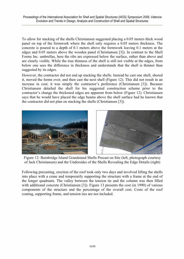
To allow for stacking of the shells Christiansen suggested placing a 0.05 meters thick wood panel on top of the formwork where the shell only requires a 0.05 meters thickness. The concrete is poured to a depth of 0.1 meters above the formwork leaving 0.1 meters at the edges and 0.05 meters above the wooden panel (Christiansen [3]). In contrast to the Shell Forms Inc. umbrellas, here the ribs are expressed below the surface, rather than above and are clearly visible. While the true thinness of the shell is still not visible at the edges, from below one sees the difference in thickness and understands that the shell is thinner than suggested by its edges. However, the contractor did not end up stacking the shells. Instead he cast one shell, shored it, moved the forms over, and then cast the next shell (Figure 12). This did not result in an increase in cost; it was simply the contractor’s preference (Christiansen [3]). Because Christiansen detailed the shell for his suggested construction scheme prior to the contractor’s change the thickened edges are apparent from below (Figure 12). Christiansen says that he would have placed the edge beams above the shell surface had he known that the contractor did not plan on stacking the shells (Christiansen [3]).
Figure 12: Bainbridge Island Grandstand Shells Precast on Site (left, photograph courtesy of Jack Christiansen) and the Undersides of the Shells Revealing the Edge Details (right)
Following precasting, erection of the roof took only two days and involved lifting the shells into place with a crane and temporarily supporting the structure with a frame at the end of the longer quadrants. The valley between the tension tie and the column was then filled with additional concrete (Christiansen [3]). Figure 13 presents the cost (in 1990) of various components of the structure and the percentage of the overall cost. Costs of the roof coating, supporting frame, and tension ties are not included.
1630

Proceedings of the International Association for Shell and Spatial Structures (IASS) Symposium 2009, Valencia Evolution and Trends in Design, Analysis and Construction of Shell and Spatial Structures
Item Quantity Unit cost ($) Total cost ($) % of overall cost Concrete 63.5 m3 50 4,150 5 Concrete pump 18 hr 1,225 1 Finishing 929 m2 0.6 6,000 7 Form material 0.4 5,000 6 Reinforcement 25,000 lb 25 10,000 12 Labor (incl.) 2,000 hr 50,000 58 Crane 16.5 hr 1 6,200 7 Structural Steel 3,030 lb 3,030 4
Figure 13: Construction Costs for the Bainbridge Island Grandstand (this table is a reproduction of Table 4 – “Structural cost summary for
athletic field grandstand roof” from Christiansen [1])
The overall cost of the grandstand was $85,605 in 1990. Using the Engineering News-Record Construction Cost Index from March 2009 to account for inflation, the equivalent cost is $154,386 (ENR Cost Indexes. . . [6]). Labor is the largest cost followed by reinforcing steel, form material, the crane, the finishing, concrete, and the concrete pump. The reuse of formwork reduced the cost of this component and the overall cost of the structure. The Bainbridge Island Grandstand (Figure 14) is one of Christiansen’s favorite structures because it is in his hometown, his son was the architect for the project, and it had a low cost while being elegant (Christiansen [3]). Again, economy and aesthetics are central to Christiansen’s design philosophy.
Figure 14: Bainbridge Island Grandstand (photograph courtesy of Jack Christiansen)
5. Conclusion Christiansen was only able to build shells in competition with other structural types because of his focus on economical construction. He achieved this economy through formwork reuse. For the standard umbrellas of Shell Forms Inc. this meant creating forms that could be reused for different jobs. For his one-of-a-kind structures in which the forms were specific to the project, the forms were reused as many times as possible within that particular project. Christiansen notes that “the total cost of any concrete structure is at least
1631

Proceedings of the International Association for Shell and Spatial Structures (IASS) Symposium 2009, Valencia Evolution and Trends in Design, Analysis and Construction of Shell and Spatial Structures
50% in the formwork which is built and thrown away” (Christiansen [3]). Consequently any reuse of formwork results in a reduction of cost and through substantial reuse the cost of Christiansen’s shells could compete with other structural systems. Expanding on Christiansen’s idea, to achieve even greater reuse, a family of related forms can be generated from the same set of formwork. Not only can formwork for square umbrellas be used to create a variety of sizes of square umbrellas, but it can also be used to create rectangular and hexagonal umbrellas. Christiansen only had the opportunity to use hexagonal umbrellas for one project, but he feels that the form offers advantages over square umbrellas (Christiansen [3]). Following his first project, Christiansen provided a suggested formwork system for every project completed thereafter (Christiansen [3]). Figure 15 shows his suggestion for constructing a cylindrical shell.
Figure 15: Christiansen’s Sketch for Suggested from Details for a Cylinder
(schematic courtesy of Jack Christiansen)
According to Christiansen: This is going beyond the normal structural engineering practice where you leave forming up to the contractor and describe the structure and let him figure out how to form it. But because this was a relatively new kind of thing, new to the local contractors, you will find on every job without exception there is a suggested, and you use the term suggested because you didn’t tell the contractor how to do his work because there’s liability problems there, suggested formwork system (Christiansen [3]).
Christiansen understood that local contractors were not familiar with these structures and that he would need to educate them. At times Christiansen’s sequences were not used. When this was the case, often during construction, the contractor would express that he wished that he had followed Christiansen’s suggestions (Christiansen [3]). Christiansen’s experience developing these construction schemes did not stem from observations in the field, but rather from “logic and common sense; you know how to build things” (Christiansen [3]). He was able to visualize the way in which a structure could be
1632

Proceedings of the International Association for Shell and Spatial Structures (IASS) Symposium 2009, Valencia Evolution and Trends in Design, Analysis and Construction of Shell and Spatial Structures
economically constructed and from the outset integrated this into his design of the final structure. From Christiansen’s concern with economic construction and through the study of works of other aesthetically sensitive structural designers, came Christiansen’s desire to generate elegant, structurally expressive forms. While Christiansen often collaborated with architects, the forms discussed in this paper can be attributed to Christiansen. The potential for new visually interesting shell forms exists if individuals follow Christiansen’s governing design principals. If shells are to be built, the designer must have a builder’s mentality and consider construction and design simultaneously.
Acknowledgement The author would like to acknowledge Jack Christiansen for providing copies of his writings, photographs, and structural drawings and Professor David P. Billington (Princeton University) for advising the thesis from which this paper was adapted. Additionally, the Department of Civil and Environmental Engineering and the School of Engineering and Applied Science at Princeton University funded the author’s trip to Seattle to visit both Christiansen and his structures.
References [1] Christiansen J.V., Economics of Hyperbolic Paraboloid Concrete Shells. Concrete
International, August 1990; 24-29. [2] Christiansen J.V., Personal Correspondence with Segal E., 16 April 2008; 1. [3] Christiansen J.V., Personal Interview with Segal E., 13 March 2008. [4] Christiansen J.V., unpublished notes from a presentation given at ACI/ASCE Joint
Committee 331 Technical Session (Boston, March 1991); 1. Courtesy of Christiansen J.V. this document is located in the Princeton University Maillart Archive.
[5] Domes and Shells Designed by Skilling, Helle, Christiansen, Robertson; 9. Courtesy of Christiansen J.V. this document is located in the Princeton University Maillart Archive.
[6] ENR Cost Indexes in 20 Cities, 1983-2009. Engineering News-Record, 23 March 2009; 262; no. 9; 39-42.
[7] Proctor M., Movable Forms for Six-Sided Hyperbolic Shells. Journal of the American Concrete Institute, June 1963; 60; no. 6; 693-696.
[8] Segal E., This paper was adapted from the author’s unpublished Master’s Thesis, The Thin Concrete Shells of Jack Christiansen. Department of Civil and Environmental Engineering, Princeton University; May 2008.
[9] Shell Forms Give You a Choice of Two Types of All Concrete Buildings. . . Either One Shows You a Lower Net Cost than Any Other Type of Construction; 2. Courtesy of Christiansen J.V. this Shell Forms Inc. brochure is located in the Princeton University Maillart Archive.
1633


