The texts and data in this catalogue are
44
Transcript of The texts and data in this catalogue are

Important notice
The texts and data in this catalogue arenot binding and we reserve the right to make modifications
without prior notice. Please do not hesitate tocontact us for any further technical information you may require.
ORGANIZATION OF MANUFACTURING PROCESS AND MARKETING
Avvertenza importante
Tutte le descrizioni e i dati riportati nel presente catalogonon sono impegnativi e ci riserviamo il diritto di modificarli
senza darne preavviso. Per particolari informazionitecniche si prega di farne richiesta al nostro ufficio.
GESTIONE DELLE FASI DI LAVORAZIONE E COMMERCIALIZZAZIONE
rev. 00 P.3
JM-GM-JMM
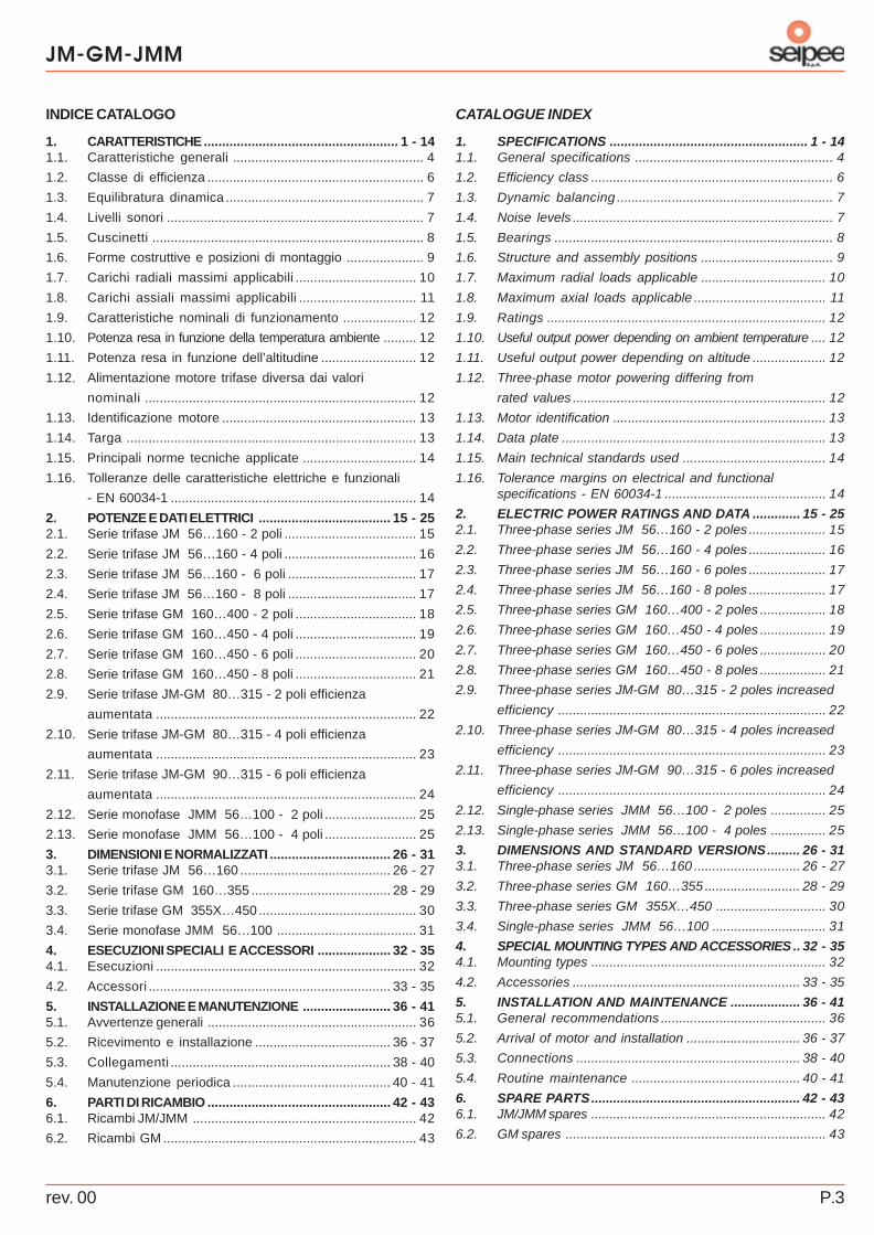
CATALOGUE INDEX
1. SPECIFICATIONS ...................................................... 1 - 141.1. General specifications ...................................................... 4
1.2. Efficiency class .................................................................. 6
1.3. Dynamic balancing ........................................................... 7
1.4. Noise levels ....................................................................... 7
1.5. Bearings ............................................................................ 8
1.6. Structure and assembly positions .................................... 9
1.7. Maximum radial loads applicable .................................. 10
1.8. Maximum axial loads applicable .................................... 11
1.9. Ratings ............................................................................ 12
1.10. Useful output power depending on ambient temperature .... 12
1.11. Useful output power depending on altitude .................... 12
1.12. Three-phase motor powering differing from
rated values ..................................................................... 12
1.13. Motor identification .......................................................... 13
1.14. Data plate ........................................................................ 13
1.15. Main technical standards used ....................................... 14
1.16. Tolerance margins on electrical and functionalspecifications - EN 60034-1 ............................................ 14
2. ELECTRIC POWER RATINGS AND DATA ............. 15 - 252.1. Three-phase series JM 56…160 - 2 poles ..................... 15
2.2. Three-phase series JM 56…160 - 4 poles ..................... 16
2.3. Three-phase series JM 56…160 - 6 poles ..................... 17
2.4. Three-phase series JM 56…160 - 8 poles ..................... 17
2.5. Three-phase series GM 160…400 - 2 poles .................. 18
2.6. Three-phase series GM 160…450 - 4 poles .................. 19
2.7. Three-phase series GM 160…450 - 6 poles .................. 20
2.8. Three-phase series GM 160…450 - 8 poles .................. 21
2.9. Three-phase series JM-GM 80…315 - 2 poles increased
efficiency ......................................................................... 22
2.10. Three-phase series JM-GM 80…315 - 4 poles increased
efficiency ......................................................................... 23
2.11. Three-phase series JM-GM 90…315 - 6 poles increased
efficiency ......................................................................... 24
2.12. Single-phase series JMM 56…100 - 2 poles ............... 25
2.13. Single-phase series JMM 56…100 - 4 poles ............... 25
3. DIMENSIONS AND STANDARD VERSIONS......... 26 - 313.1. Three-phase series JM 56…160 ............................. 26 - 27
3.2. Three-phase series GM 160…355 .......................... 28 - 29
3.3. Three-phase series GM 355X…450 .............................. 30
3.4. Single-phase series JMM 56…100 ............................... 31
4. SPECIAL MOUNTING TYPES AND ACCESSORIES .. 32 - 354.1. Mounting types ................................................................ 32
4.2. Accessories .............................................................. 33 - 35
5. INSTALLATION AND MAINTENANCE ................... 36 - 415.1. General recommendations ............................................. 36
5.2. Arrival of motor and installation ............................... 36 - 37
5.3. Connections ............................................................. 38 - 40
5.4. Routine maintenance .............................................. 40 - 41
6. SPARE PARTS......................................................... 42 - 436.1. JM/JMM spares ................................................................ 42
6.2. GM spares ....................................................................... 43
INDICE CATALOGO
1. CARATTERISTICHE..................................................... 1 - 141.1. Caratteristiche generali .................................................... 4
1.2. Classe di efficienza ........................................................... 6
1.3. Equilibratura dinamica ...................................................... 7
1.4. Livelli sonori ...................................................................... 7
1.5. Cuscinetti .......................................................................... 8
1.6. Forme costruttive e posizioni di montaggio ..................... 9
1.7. Carichi radiali massimi applicabili ................................. 10
1.8. Carichi assiali massimi applicabili ................................ 11
1.9. Caratteristiche nominali di funzionamento .................... 12
1.10. Potenza resa in funzione della temperatura ambiente ......... 12
1.11. Potenza resa in funzione dell’altitudine .......................... 12
1.12. Alimentazione motore trifase diversa dai valori
nominali .......................................................................... 12
1.13. Identificazione motore ..................................................... 13
1.14. Targa ............................................................................... 13
1.15. Principali norme tecniche applicate ............................... 14
1.16. Tolleranze delle caratteristiche elettriche e funzionali
- EN 60034-1 ................................................................... 14
2. POTENZE E DATI ELETTRICI .................................... 15 - 252.1. Serie trifase JM 56…160 - 2 poli .................................... 15
2.2. Serie trifase JM 56…160 - 4 poli .................................... 16
2.3. Serie trifase JM 56…160 - 6 poli ................................... 17
2.4. Serie trifase JM 56…160 - 8 poli ................................... 17
2.5. Serie trifase GM 160…400 - 2 poli ................................. 18
2.6. Serie trifase GM 160…450 - 4 poli ................................. 19
2.7. Serie trifase GM 160…450 - 6 poli ................................. 20
2.8. Serie trifase GM 160…450 - 8 poli ................................. 21
2.9. Serie trifase JM-GM 80…315 - 2 poli efficienza
aumentata ....................................................................... 22
2.10. Serie trifase JM-GM 80…315 - 4 poli efficienza
aumentata ....................................................................... 23
2.11. Serie trifase JM-GM 90…315 - 6 poli efficienza
aumentata ....................................................................... 24
2.12. Serie monofase JMM 56…100 - 2 poli ......................... 25
2.13. Serie monofase JMM 56…100 - 4 poli ......................... 25
3. DIMENSIONI E NORMALIZZATI ................................. 26 - 313.1. Serie trifase JM 56…160 ......................................... 26 - 27
3.2. Serie trifase GM 160…355 ...................................... 28 - 29
3.3. Serie trifase GM 355X…450 ........................................... 30
3.4. Serie monofase JMM 56…100 ...................................... 31
4. ESECUZIONI SPECIALI E ACCESSORI .................... 32 - 354.1. Esecuzioni ....................................................................... 32
4.2. Accessori .................................................................. 33 - 35
5. INSTALLAZIONE E MANUTENZIONE ........................ 36 - 415.1. Avvertenze generali ......................................................... 36
5.2. Ricevimento e installazione ..................................... 36 - 37
5.3. Collegamenti ............................................................ 38 - 40
5.4. Manutenzione periodica ........................................... 40 - 41
6. PARTI DI RICAMBIO .................................................. 42 - 436.1. Ricambi JM/JMM ............................................................. 42
6.2. Ricambi GM ..................................................................... 43
JM-GM-JMM
rev. 00P. 4
1. SPECIFICATIONS1. CARATTERISTICHE1.1. General specifications
J M / G M / JMM series
JM: IEC 56...160; 0.09...18.5 kW; 2,4,6,8 poles three-phaseGM: IEC 160...450; 4...900 kW; 2,4,6,8 poles three-phaseJMM: IEC 56...100; 0.09...2.2 kW; 2,4 poles single-phaseMotors JM, GM and JMM are not suitable for use in placeswhere there is a risk of explosion.
Standard asynchronous three-phase electric motor withshort-circuited squirrel-cage rotor for general purposes inindustrial applications; enclosed, externally fan-cooled (withIC 411 cooling method), thermal insulation class F (class Bmotor overtemperature class with standard power; class B orB/F for the remaining three-phase and single-phase motors).Motor designed for continuous duty (S1) at rated voltage andfrequency.Ambient air temperature: –15 to +40 °C.Maximum altitude: 1000 m above sea level.
Protection class of motor housing IP 55: the cooling fan of themotor, which is installed outside the housing, is protected by afan cover.
Fan cover made of steel sheet.
Cooling fan: two-way with radial blades, connected to the driveshaft. JM 56...160; GM 160...355 and JMM 56...100: reinforcedpolyproprlene fan. GM 355X…450: aluminium cooling fan.
Housing: JM 56...160 and JMM 56...100: housing in die-castlight aluminium alloy with excellent thermal conductivity andcorrosion resistance. Ring for lifting the motor alone from size100. GM 160...450: cast iron housing with eyebolt for liftingthe motor alone.
Shields and flanges: JM 56...160 and JMM 56...100: shieldsand flanges in die-cast light aluminium alloy, reinforced steelbearing housings from size 90 onwards. Flange B14 JM 160 incast iron. GM 160..0.450: cast iron shields and flanges.
Stands: JM 56...160 and JMM 56…100: aluminium stands.The stands can be installed on 3 sides of the motor so as toposition the terminal box on the required side: IM B3, B5,B35, B14, B34. The standard IMB3 motor is supplied with theterminal box on the top of the housing.GM 160..0.450: castiron stands enbloc with the housing. The standard IMB3 motoris supplied with the terminal box on the top of the housing. Itcan be installed at the side on request.
Drive shaft in C45 carbon steel with standard cylindrical ends,threaded shaft-head hole and key. GM series with axially lockeddrive shaft.
Terminal box: standard position at the top and near the controlside. JM 56...160: in die-cast light aluminium alloy (sizes 56and 90...160, positionable through 90° turns; size 63…80 enblocwith the housing, with bilateral cable access). GM 160...355:made of steel (terminal box positionable through 90° turns).
1.1. Caratteristiche generali
Serie J M / G M / JMM
JM: IEC 56...160; 0,09...18.5 kW; 2,4,6,8 poli trifaseGM: IEC 160...450; 4...900 kW; 2,4,6,8 poli trifaseJMM: IEC 56...100; 0,09...2.2 kW; 2,4 poli monofaseMotori JM, GM e JMM non idonei ad ambienti con pericolo diesplosione.
Motore elettrico asincrono trifase normalizzato per usogenerale in applicazioni industriali, con rotore a gabbia incorto circuito, chiuso, autoventilato esternamente (metodo diraffreddamento IC 411), classe termica d’isolamento F(sovratemperatura motore classe B per tutti i motori con poten-za normalizzata; classe B o B/F per i rimanenti motori trifasi emonofasi). Progettato per operare in servizio continuo (S1) atensione e frequenza nominali.Temperatura aria dell’ambiente di lavoro: –15 ÷ +40 °C.Altitudine massima: 1000 m sul livello del mare.
Grado di protezione involucro motore IP 55: la ventola diraffreddamento del motore, esterna alla carcassa, è protettatramite apposita calotta copriventola.
Copriventola di lamiera di acciaio.
Ventola di raffreddamento: bi-direzionale a pale radiali,calettata sull’albero motore. JM 56...160; GM 160...355 e JMM56...100: ventola in polipropilene rinforzato. GM 355X…450:ventola di raffreddamento in alluminio.
Carcassa: JM 56...160 e JMM 56...100: carcassa di lega leg-gera d’alluminio pressofusa, ottima conducibilità termica, ec-cellente resistenza alla corrosione. Anello di sollevamento solomotore a partire dalla grandezza 100. GM 160...450: carcassadi ghisa con golfare di sollevamento solo motore.
Scudi e flange: JM 56...160 e JMM 56...100: scudi e flange dilega leggera d’alluminio pressofusa, sedi dei cuscinetti rinfor-zate in acciaio a partire dalla grandezza 90. Flangia B14 JM160 di ghisa. GM 160...450: scudi e flange di ghisa.
Piedi: JM 56...160 e JMM 56…100: piedi di alluminio. Possi-bilità di montare i piedi sui 3 lati del motore al fine di avere lascatola morsettiera su lato desiderato: IM B3, B5, B35, B14,B34. Di serie il motore IMB3 è fornito con scatola morsettierain alto. GM 160...450: piedi di ghisa solidali alla carcassa. Diserie il motore IMB3 è fornito con scatola morsettiera in alto,laterale a richiesta.
Albero motore di acciaio al carbonio C45, con estremitàcilindriche, foro filettato in testa e linguetta unificati. Serie GMcon albero motore bloccato assialmente.
Scatola morsettiera: posizione standard in alto e in prossi-mità del lato comando. JM 56...160: in lega leggera d’alluminiopressofusa (gr. 56 e 90...160 orientabile di 90° in 90°; gr. 63…80solidale alla carcassa con accesso cavi bilaterale). GM160...355: in acciaio (scatola morsettiera orientabile di 90° in 90°).

rev. 00 P.5
JM-GM-JMM
1. SPECIFICATIONS1. CARATTERISTICHEGM 355X…450: made of cast iron. JMM 56…100: made ofhigh-strength thermoplastic material. Feeder cable input: JMand GM standard on right-hand side, JMM on side oppositecontrols.
Terminal box for powering the motor with 6 terminals.
Earth terminal installed inside the terminal box. Additionalexternal terminal for GM 315…450.
Stator winding: copper wire with double coating,impregnated in an autoclave with high quality resin allowing themotor to be used in a tropical climate without further treatments.Phase windings accurately insulated (in each slot and on thewinding top). Accurate insulation of the winding leads (phasebeginning leads). Insulating system in thermal class F.
Winding protection against overtemperatures:JM 160 and GM 160...200 are equipped with bimetallic thermalprobes as part of the standard equipment. GM 250...450 areequipped with bimetallic thermal probes and with thermistor(PTC) probes as part of the standard equipment. Theterminals of the probes are installed inside the terminal box.The relative cable gland stuffing box is installed on the sideopposite to the motor’s feeder cable input.
Rotor short-circuited squirrel-cage rotor in die-cast aluminium.
The motors are coated with nitrocombined paint able towithstand normal industrial environments. This coating can betreated with further finishing coats of one-pack synthetic paints.JM 56...160 and JMM 56…100: RAL 9006 (silver grey); GM160...450: RAL 5010 (blue).
Applications with invertersJM and GM motors are suitable for operation with inverters(limit values: power-supply voltage U
N < 500 V, voltage peaks
Umax
< 1000 V, voltage gradients dU/dt < 1kV/ms. Pleasecontact us if > 500 V power-supply voltage values are required.Use of an inverter requires the following precautions: The entityof these peaks/gradients is bound to the inverter’s power-supplyvoltage and the length of the motor’s feeder cables. To limitthis entity, it is advisable to use special filters (at the purchaser’scharge) installed between the inverter and motor (obligatory for> 30 m feeder cables). It is also advisable to choose a motorwith an electrically insulated rear bearing. There is a wide varietyof mounting types, forced ventilation, encoders, bimetallicthermal probes or thermistor probes, etc. (consult “Specialmounting types and accessories”)
On request, the JM 56…160 and GM 160…355 series
motors can be supplied in mounting types for use in placeswith potentially explosive atmospheres in accordance with ATEXdirective 94/9/EC group II class 3D for zone 22 (consult“Special mounting types and accessories”).
GM 355X…450: in ghisa. JMM 56…100: in materialetermoplastico ad alta resistenza. Entrata cavi d’alimenta-zione: JM e GM di serie lato destro, JMM lato opposto co-mando.
Morsettiera per l’alimentazione del motore a 6 morsetti.
Morsetto di terra posizionato all’interno della scatolamorsettiera. Morsetto supplementare esterno per GM315…450.
Avvolgimento statorico: filo di rame doppiamente smaltato,sistema di impregnazione in autoclave con resine di alta qualità,che permettono l’impiego in clima tropicale senza ulterioretrattamenti. Accurata separazione degli avvolgimenti di fase (incava e in testata); accurato isolamento della “trecciola” (cavi diinizio fase). Sistema di isolamento in classe termica F.
Protezione dell’avvolgimento da sovratemperatura:JM 160 e GM 160...200 sono equipaggiati di serie con sondetermiche bimetalliche. GM 250...450 sono equipaggiati di seriecon sonde termiche bimetalliche e con sonde termiche atermistori (PTC). I terminali delle sonde sono all’interno dellascatola morsettiera. Il relativo pressacavo è posizionato sullato opposto a quello d’entrata dei cavi d’alimentazione delmotore.
Rotore a gabbia di scoiattolo in corto circuito pressofuso inalluminio.
Motori verniciati con smalto nitrocombinato idoneo a resi-stere ai normali ambienti industriali e a consentire ulteriori fini-ture con vernici sintetiche monocomponente.JM 56...160 e JMM 56…100: RAL 9006 (grigio argento); GM160...450: RAL 5010 (blù).
Funzionamento con inverterI motori JM e GM, sono adatti al funzionamento con inverter(valori limiti: tensione alimentazione U
N < 500 V, picchi di ten-
sione Umax
< 1000 V, gradienti di tensione dU/dt < 1kV/ms. Pertensione di alimentazione > 500 V interpellarci .L’utilizzodell’inverter richiede delle precauzioni: l’entità di tali picchi/gradienti è legata al valore della tensione di alimentazionedell’inverter e alla lunghezza dei cavi di alimentazione del mo-tore. Per limitare tale entità si consiglia l’utilizzo di appositifiltri (a cura dell’acquirente) posti tra inverter e motore (obbliga-tori per cavi di alimentazione > di 30 m). Si consiglia inoltre dirichiedere il motore con il cuscinetto posteriore isolato elettri-camente. Ampia disponibilità di esecuzioni, servoventilazione,encoder, sonde termiche bimetalliche o a termistori, ecc. (ve-dere “Esecuzioni speciali e accessori”).
I motori della serie JM 56…160 e GM 160…355, sono
fornibili a richiesta in esecuzione per utilizzo in ambienti conatmosfere potenzialmente esplosive secondo la direttiva ATEX94/9/CE gruppo II categoria 3D per zona 22 (vedere “Ese-cuzioni speciali e accessori”).
JM-GM-JMM
rev. 00P. 6
1. SPECIFICATIONS1. CARATTERISTICHE
COSTI - COSTSEff2:Energia utilizzata in un anno [ kWh / anno ] - Energy used in one year [ kWh / year ]: E
2 = (P
n * L% / 100) / (η
2% / 100) * H
Costo annuale dell’energia [ Euro / anno ] - Annual cost of energy [ Euro / year ]: CA2 = (P
n * L% / 100) / (η
2% / 100) * H * C
Eff1:Energia utilizzata in un anno [ kWh / anno ] - Energy used in one year [ kWh / year ]: E
1 = (P
n * L% / 100) / (η
1% / 100) * H
Costo annuale dell’energia [ Euro / anno ] - Annual cost of energy [ Euro / year ]: CA1 = (P
n * L% / 100) / (η1% / 100) * H * C
RISPARMI - SAVINGSEnergia risparmiata in un anno [kWh/anno] - Energy saved in one year [kWh/year]: E = E2 - E1
Risparmio annuale [Euro/ anno] - Money saved in one year [Euro/year]: RA = CA2 - CA1
Tempo di recupero del maggiore costo del motore [Mesi] - Pay-back time of the motor [Months]: TR = (Pr1- Pr2) / RA * 12
dove - where:- Pn [kW]: Potenza nominale del motore - Rated power of the motor;- L%: Coefficiente (%) di utilizzo della potenza nominale del motore - Use-coefficient (%) of the rated power of the motor;- ηηηηη2%: Rendimento (%) del motore in eff2 - Efficiency (%) of the eff2 -motor;- ηηηηη1%: Rendimento (%) del motore in eff1 - Efficiency (%) of the eff1 -motor;- H [h/anno-year]: Utilizzo annuale del motore - Annual use of the motor;- C [Euro/kWh]: Costo del kWh - Cost per kWh;- Pr2 [Euro]: Prezzo del motore in eff2 - Price of the eff2 -motor;- Pr1 [Euro]: Prezzo del motore in eff1 - Price of the eff1-motor.
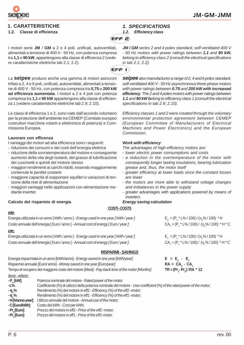
1.2. Efficiency class
JM / GM series 2 and 4 poles standard, self-ventilated 400 V- 50 Hz motors with power ratings between 1.1 and 90 kW,belong to efficiency class 2 (consult the electrical specificationsin tab 2.1; 2.2).
seipee also manufactures a range of 2, 4 and 6 poles standard,self-ventilated 400 V - 50 Hz asynchronous three-phase motorswith power ratings between 0.75 and 200 kW with increasedefficiency. The 2 and 4 poles motors with power ratings between1.1 and 90 kW belong to efficiency class 1 (consult the electricalspecifications in tab 2.9; 2.10).
Efficiency classes 1 and 2 were created through the voluntaryenvironmental protection agreement between CEMEP(European Committee of Manufacturers of ElectricalMachines and Power Electronics) and the EuropeanCommission.
Work with efficiencyThe advantages of high-efficiency motors are:- lower electric power consumptions and costs- a reduction in the overtemperature of the motor with
consequently longer lasting insulations, bearing lubricationgrease and, thus, the motor itself
- greater efficiency at lower loads since the constant lossesare lower
- the motors are more able to withstand voltage changesand imbalances in the power supply
- greater advantages with applications powered by means ofinverters.
Energy saving calculation
1.2. Classe di efficienza
I motori serie JM / GM a 2 e 4 poli, unificati, autoventilati,alimentati a tensione di 400 V - 50 Hz, con potenza compresatra 1,1 e 90 kW, appartengono alla classe di efficienza 2 (vede-re caratteristiche elettriche tab 2.1; 2.2).
La seipee produce anche una gamma di motori asincronitrifasi a 2, 4 e 6 poli, unificati, autoventilati, alimentati a tensio-ne di 400 V - 50 Hz, con potenza compresa tra 0,75 e 200 kWad efficienza aumentata. I motori a 2 e 4 poli con potenzacompresa tra 1,1 e 90 kW appartengono alla classe di efficien-za 1 (vedere caratteristiche elettriche tab 2.9; 2.10).
Le classi di efficienza 1 e 2, sono nate dall’accordo volontarioper la protezione dell’ambiente tra CEMEP (Comitato europeocostruttori macchine rotanti e elettronica di potenza) e Com-missione Europea.
Lavorare con efficenzaI vantaggi dei motori ad alta efficienza sono i seguenti:- riduzione dei consumi e dei costi dell’energia elettrica- riduzione della sovratemperatura del motore e conseguente
aumento della vita degli isolanti, del grasso di lubrificazionedei cuscinetti e quindi del motore stesso
- maggiori rendimenti ai carichi ridotti, essendo maggiormentecontenute le perdite costanti
- maggiore capacità di sopportare squilibri e variazioni di ten-sione della rete di alimentazione
- maggiori vantaggi nelle applicazioni con alimentazione me-diante inverter.
Calcolo del risparmio di energia
rev. 00 P.7
JM-GM-JMM
1. SPECIFICATIONS1. CARATTERISTICHE
Tab. 1.2 / Tab. 1.2
Tab. 1.1 / Tab. 1.1
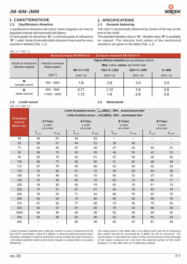
1.3. Dynamic balancing
The rotor is dynamically balanced by means of the key at theend of the shaft.The standard vibration class is “N”. Vibration class “R” is availableon request. The intensity limit values of the mechanicalvibrations are given in the table (Tab. 1.1).
The values given in the table refer to an idling motor and 50 Hz frequency(the values should be increased by 2 dB(A) for 60 Hz versions). Thesound power is calculated by means of the sound pressure level (averageof the values measured at 1 [m] from the external surface of the motorsituated in a free field and on a reflecting surface).
1.4. Noise levels
1.3. Equilibratura dinamica
L’equilibratura dinamica del rotore viene eseguita con mezzalinguetta inserita nell’estremità dell’albero.Di serie grado di vibrazione “N”; a richiesta grado di vibrazione“R”. I valori limite d’intensità delle vibrazioni meccaniche sonoriportati in tabella (Tab. 1.1).
I valori riportati in tabella sono validi per motore a vuoto e frequenza 50 Hz(per 60 Hz aumentare i valori di 2 dB(A)). Il valore di potenza sonora vienecalcolato mediante il livello di pressione sonora (media dei valori misurati a1 [m] dalla superficie esterna del motore situato in campo libero e su pianoriflettente).
1.4. Livelli sonori
JM-GM-JMM
rev. 00P. 8
1. SPECIFICATIONS1. CARATTERISTICHE
Tab. 1.3 / Tab. 1.3
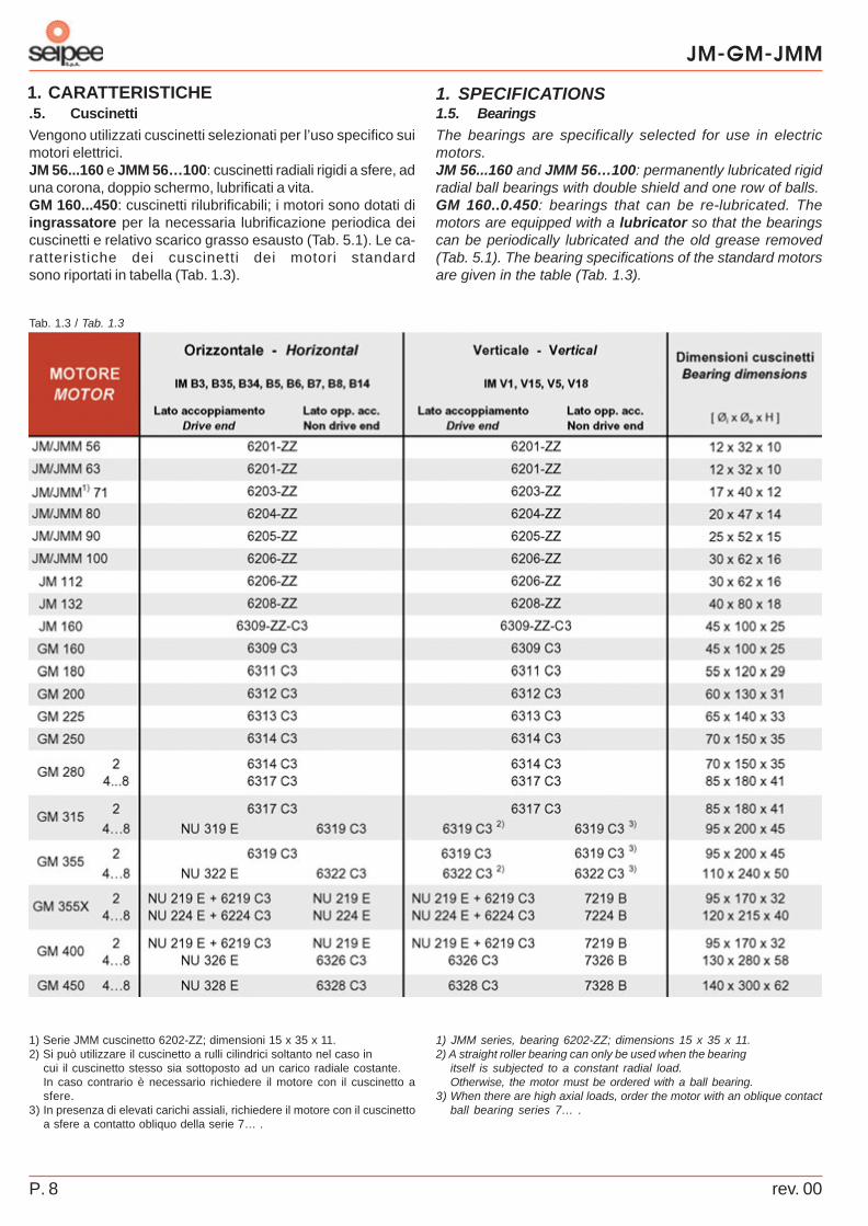
1.5. Bearings
The bearings are specifically selected for use in electricmotors.JM 56...160 and JMM 56…100: permanently lubricated rigidradial ball bearings with double shield and one row of balls.GM 160..0.450: bearings that can be re-lubricated. Themotors are equipped with a lubricator so that the bearingscan be periodically lubricated and the old grease removed(Tab. 5.1). The bearing specifications of the standard motorsare given in the table (Tab. 1.3).
1) JMM series, bearing 6202-ZZ; dimensions 15 x 35 x 11.2) A straight roller bearing can only be used when the bearing
itself is subjected to a constant radial load.Otherwise, the motor must be ordered with a ball bearing.
3) When there are high axial loads, order the motor with an oblique contactball bearing series 7… .
.5. Cuscinetti
Vengono utilizzati cuscinetti selezionati per l’uso specifico suimotori elettrici.JM 56...160 e JMM 56…100: cuscinetti radiali rigidi a sfere, aduna corona, doppio schermo, lubrificati a vita.GM 160...450: cuscinetti rilubrificabili; i motori sono dotati diingrassatore per la necessaria lubrificazione periodica deicuscinetti e relativo scarico grasso esausto (Tab. 5.1). Le ca-ratteristiche dei cuscinetti dei motori standardsono riportati in tabella (Tab. 1.3).
1) Serie JMM cuscinetto 6202-ZZ; dimensioni 15 x 35 x 11.2) Si può utilizzare il cuscinetto a rulli cilindrici soltanto nel caso in
cui il cuscinetto stesso sia sottoposto ad un carico radiale costante.In caso contrario è necessario richiedere il motore con il cuscinetto asfere.
3) In presenza di elevati carichi assiali, richiedere il motore con il cuscinettoa sfere a contatto obliquo della serie 7… .

rev. 00 P.9
JM-GM-JMM
1. SPECIFICATIONS1. CARATTERISTICHE
Tab. 1.4 / Tab. 1.4
1.6. Structure and assembly positions
The versions available are IM B3, IM B5, IM B14 andcombined structures IM B35 (B3/B5) and IM B34 (B3/B14).The motors can also function in the corresponding verticalshaft configurations. Specify the complete IM code whenordering the motor. Consult the tables (Tab. 1.3, Tab. 1.4,Tab. 1.5, Tab. 1.6) to find out whether there are anyrestrictions. The horizontal shaft configuration is indicatedon the motor’s data plate. The mounting types and assemblypositions are given in the table (Tab. 1.4).
Possible Consult seipee motors1) Motors with stands2) Motors with flange: through holes3) Motors with flange: threaded holes
1.6. Forme costruttive e posizioni di montaggio
Le forme costruttive previste sono IM B3, IM B5, IM B14 eforme combinate IM B35 (B3/B5) e IM B34 (B3/B14). I motoripossono funzionare anche nelle corrispondenti forme costruttivead asse verticale; al momento della richiesta del motore occor-re specificarne il codice IM completo. Consultare le tabelle (Tab.1.3, Tab. 1.4, Tab. 1.5, Tab. 1.6) per verificare eventuali restri-zioni. Sulla targa del motore rimane indicata la forma costruttivaad asse orizzontale. Le forme costruttive e le posizioni di mon-taggio sono riportate in tabella (Tab. 1.4).
Possibile Consultare seipee motori1) Motori con piedi2) Motori con flangia: fori passanti3) Motori con flangia: fori filettati

JM-GM-JMM
rev. 00P. 10
1. SPECIFICATIONS1. CARATTERISTICHE
xE
FFFF
XrXor
Xorxr⋅
−−= maxmax,max,
max,max,
Tab. 1.5 / Tab. 1.5
1.7. Maximum radial loads applicable
1) In order to operate at a different frequency ff from 50 Hz, the values inthe table must be multiplied by: ( 50 / ff )
( 1 / 3 ).2) For longer bearing life values, multiply the loads in the table by the following
factors: 0.87 (30,000 hours), 0.79 (40,000 hours), 0.74 (50,000 hours)3) For the JMM series, reduce the values in the table by 20%.4) Maximum radial load applicable in relation to the mechanical strength
of the drive shaft and not the life of the bearings.
If the load is applied between sections X 0 (x = 0) and X
max (x = E)
at a distance of X [mm] from section X 0
, its maximum valueF
r max, x can be assumed to be:
where:
- Fr max,X0
[N]: Maximum radial load on a level with section X 0
given in the table (Tab. 1.5 );
- Fr max,Xmax
[N]: Maximum radial load on a level with section X
max given in the table (Tab. 1.5 );
- E [mm]: Output shaft given in the tale (Tab. 1.5 ).
1.7. Carichi radiali massimi applicabili
1) Per funzionamento ad una determinata frequenza ff diversa da 50 Hz,moltiplicare i valori di tabella per: ( 50 / ff )
( 1 / 3 ).2) Per durate maggiori dei cuscinetti moltiplicare i carichi di tabella per i
seguenti fattori: 0,87 (30.000 ore), 0,79 (40.000 ore), 0,74 (50.000 ore)3) Serie JMM ridurre i carichi riportati in tabella del 20%.4) Massimo carico radiale applicabile relativamente alla resistenza meccanica
dell’albero motore e non alla durata dei cuscinetti.
Se il carico radiale è applicato tra le sezioni X 0 (x = 0) e X
max (x = E) ad
una distanza X [mm] dalla sezione X 0
, il suo valore massimoF
r max, x può essere assunto pari a:
dove:
- Fr max,X0
[N]: Carico radiale massimo in corrispondenza dellasezione X
0 riportato in tabella (Tab. 1.5 );
- Fr max,Xmax
[N]: Carico radiale massimo in corrispondenza dellasezione X
max riportato in tabella (Tab. 1.5 );
- E [mm]: Uscita albero riportata in tabella (Tab. 1.5 ).
rev. 00 P.11
JM-GM-JMM
1. SPECIFICATIONS1. CARATTERISTICHE
Tab. 1.6 / Tab. 1.6
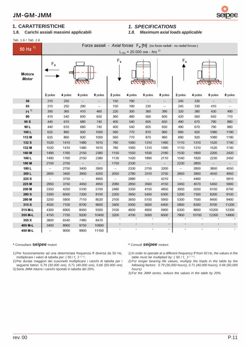
1.8. Maximum axial loads applicable
* Consult seipee motors
1) In order to operate at a different frequency ff from 50 Hz, the values in thetable must be multiplied by: ( 50 / ff )
( 1 / 3 ).2)For longer bearing life values, multiply the loads in the table by the
following factors: 0.79 (30,000 hours), 0.71 (40,000 hours), 0.66 (50,000hours)
3)For the JMM series, reduce the values in the table by 20%.
1.8. Carichi assiali massimi applicabili
* Consultare seipee motori
1)Per funzionamento ad una determinata frequenza ff diversa da 50 Hz,moltiplicare i valori di tabella per: ( 50 / ff )
( 1 / 3 ).2)Per durate maggiori dei cuscinetti moltiplicare i carichi di tabella per i
seguenti fattori: 0,79 (30.000 ore), 0,71 (40.000 ore), 0,66 (50.000 ore)3)Serie JMM ridurre i carichi riportati in tabella del 20%.

JM-GM-JMM
rev. 00P. 12
1. SPECIFICATIONS1. CARATTERISTICHE
Tab. 1.7 / Tab. 1.7
Tab. 1.9 / Tab. 1.9
Tab. 1.8 / Tab. 1.8
1.9. Ratings
The power ratings in the catalogue refer to:- continuous duty - S1- ambient air temperature: - 15 °C to + 40 °C- maximum altitude: 1000 m above sea level- power supply at the rated voltage and frequency values,
tolerated maximum voltage variation ± 5%. Consider afurther ± 5% for the maximum and minimum power supplylimits (e.g. a 230/400 V motor is suitable for mains voltagevalues up to 220/380 V and 240/415 V). Also consult Tab.1.9 and the relative notes.
1.10. Useful output power depending on ambienttemperature
1.11. Useful output power depending on altitude
1.12. Three-phase motor power supplies differing fromthe rated values (please contact us if special voltageor frequency values are required)
Important: the efficiency of a motor may drop if it is poweredwith different voltage/frequency values from the rated ones.
1) Power supply voltage not recommended if the motor is subjected toheavy duty use or long periods of continuous duty. The motor can functionwith this type of power supply, but must not be started at full load. Thepower demand must not exceed the rated value. The motor’sovertemperature may be higher.
2) The motor can function with this type of power supply, but must not bestarted at full load.
1.9. Caratteristiche nominali di funzionamento
Le potenze di catalogo sono valide per:- servizio continuo - S1- temperatura aria ambiente: - 15 °C ÷ + 40 °C- altitudine massima pari a 1.000 m s.l.m.- alimentazione a tensione e frequenza nominali, variazione
massima di tensione ammessa ± 5%. Per i limiti massimo eminimo di alimentazione, considerare un ulteriore ± 5% ( es.un motore a 230/400 V è idoneo per tensioni nominali direte fino a 220/380 V e 240/415 V). Consultare anche Tab.1.9 e relative note.
1.10. Potenza resa in funzione della temperaturaambiente
1.11. Potenza resa in funzione dell’altitudine
1.12. Alimentazione motore trifase diversa dai valorinominali (per tensioni o frequenze speciali contattarci)
Attenzione: il rendimento di un motore può diminuire quandoviene alimentato a valori di tensione/frequenza diversi da quellinominali.
1) Tensione d’alimentazione sconsigliata per impieghi gravosi e funzionamentoprolungato del motore. Il motore può funzionare con tale alimentazionema non si devono avere avviamenti a pieno carico; la potenza richiestanon deve superare il valore nominale. La sovratemperatura del motorepuò risultare maggiore.
2) Il motore può funzionare con tale alimentazione ma non si devono avereavviamenti a pieno carico.
rev. 00 P.13
JM-GM-JMM
1. SPECIFICATIONS1. CARATTERISTICHE
Tab. 1.10 / Tab. 1.10
Fig. 1.1 / Draw. 1.1
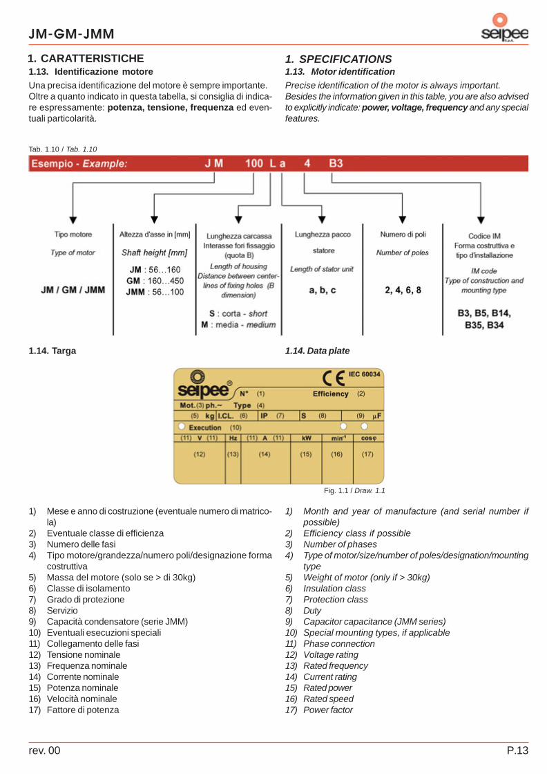
1.13. Motor identification
Precise identification of the motor is always important.Besides the information given in this table, you are also advisedto explicitly indicate: power, voltage, frequency and any specialfeatures.
1) Month and year of manufacture (and serial number ifpossible)
2) Efficiency class if possible3) Number of phases4) Type of motor/size/number of poles/designation/mounting
type5) Weight of motor (only if > 30kg)6) Insulation class7) Protection class8) Duty9) Capacitor capacitance (JMM series)10) Special mounting types, if applicable11) Phase connection12) Voltage rating13) Rated frequency14) Current rating15) Rated power16) Rated speed17) Power factor
1.14. Data plate
1.13. Identificazione motore
Una precisa identificazione del motore è sempre importante.Oltre a quanto indicato in questa tabella, si consiglia di indica-re espressamente: potenza, tensione, frequenza ed even-tuali particolarità.
1) Mese e anno di costruzione (eventuale numero di matrico-la)
2) Eventuale classe di efficienza3) Numero delle fasi4) Tipo motore/grandezza/numero poli/designazione forma
costruttiva5) Massa del motore (solo se > di 30kg)6) Classe di isolamento7) Grado di protezione8) Servizio9) Capacità condensatore (serie JMM)10) Eventuali esecuzioni speciali11) Collegamento delle fasi12) Tensione nominale13) Frequenza nominale14) Corrente nominale15) Potenza nominale16) Velocità nominale17) Fattore di potenza
1.14. Targa
JM-GM-JMM
rev. 00P. 14
1. SPECIFICATIONS1. CARATTERISTICHE
Tab. 1.11 / Tab. 1.11
Tab. 1.12 / Tab. 1.12
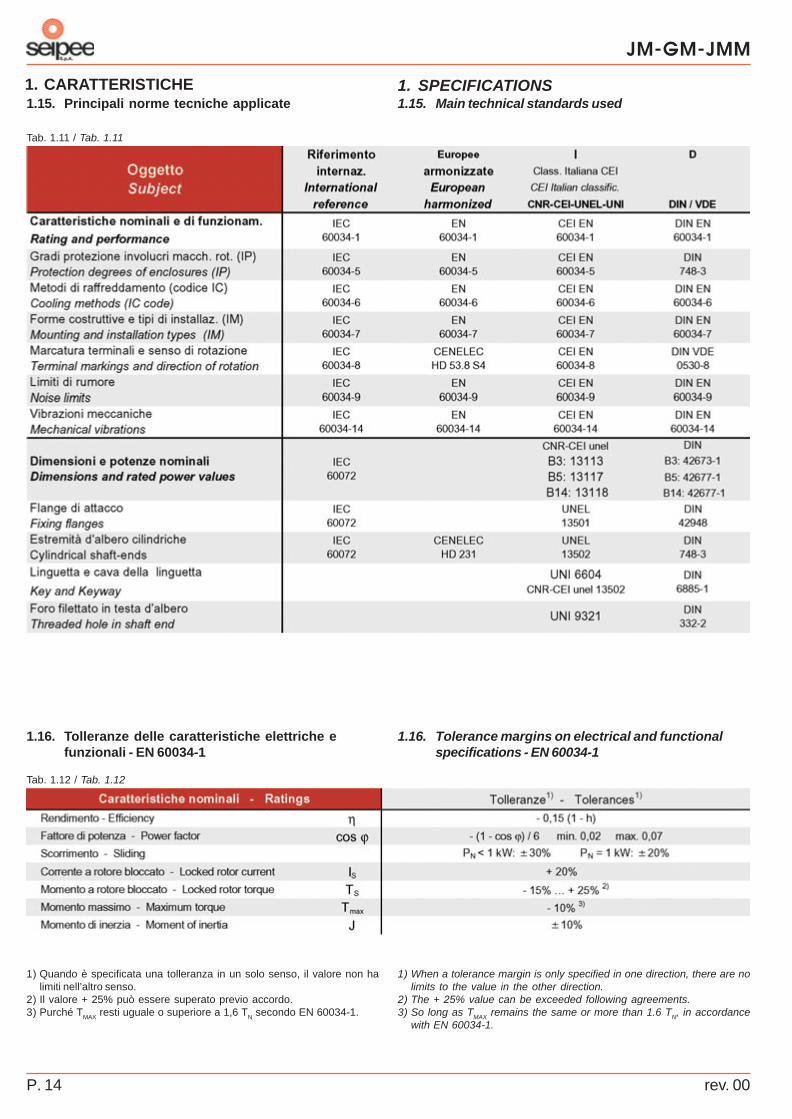
1.15. Main technical standards used
1.16. Tolerance margins on electrical and functionalspecifications - EN 60034-1
1) When a tolerance margin is only specified in one direction, there are nolimits to the value in the other direction.
2) The + 25% value can be exceeded following agreements.3) So long as TMAX remains the same or more than 1.6 TN, in accordance
with EN 60034-1.
1.15. Principali norme tecniche applicate
1.16. Tolleranze delle caratteristiche elettriche efunzionali - EN 60034-1
1) Quando è specificata una tolleranza in un solo senso, il valore non halimiti nell’altro senso.
2) Il valore + 25% può essere superato previo accordo.3) Purché TMAX resti uguale o superiore a 1,6 TN secondo EN 60034-1.

rev. 00 P.15
JM-GM-JMM
2. ELECTRIC POWER RATING AND SPECIFICATIONS2. POTENZE E DATI ELETTRICI
Tab. 2.1 / Tab. 2.1
Simboli - Symbols
PN = Potenza nominale - Rated power [kW] IN = Corrente nominale - Rated current [A]
nN = Velocità nominale - Rated speed [min-1] I S = Corrente di spunto - Breakaway starting current [A]
TN = Coppia nominale - Rated torque [Nm] cosϕ = Fattore di potenza nominale - Rated power factor
TS = Coppia di spunto - Starting torque [Nm] η = Rendimento ( Presa / Passorbita ) - Efficiency ( Pout / Pin )
Tmax = Coppia massima - Maximum torque [Nm] J = Momento d’inerzia - Moment of inertia [kg m2]
* Power or non-standard power-size match.
2.1. Three-phase series JM 56…160 - 2 poles2.1. Serie trifase JM 56…160 - 2 poli
* Potenza o corrispondenza potenza-grandezza non normalizzate.

JM-GM-JMM
rev. 00P.16
2. ELECTRIC POWER RATING AND SPECIFICATIONS2. POTENZE E DATI ELETTRICI
Tab. 2.2 / Tab. 2.2
Simboli - Symbols
PN = Potenza nominale - Rated power [kW] IN = Corrente nominale - Rated current [A]
nN = Velocità nominale - Rated speed [min-1] I S = Corrente di spunto - Breakaway starting current [A]
TN = Coppia nominale - Rated torque [Nm] cosϕ = Fattore di potenza nominale - Rated power factor
TS = Coppia di spunto - Starting torque [Nm] η = Rendimento ( Presa / Passorbita ) - Efficiency ( Pout / Pin )
Tmax = Coppia massima - Maximum torque [Nm] J = Momento d’inerzia - Moment of inertia [kg m2]
2.2. Three-phase series JM 56…160 - 4 poles
* Power or non-standard power-size match.
2.2. Serie trifase JM 56…160 - 4 poli
* Potenza o corrispondenza potenza-grandezza non normalizzate.

rev. 00 P.17
JM-GM-JMM
2. ELECTRIC POWER RATING AND SPECIFICATIONS2. POTENZE E DATI ELETTRICI
Tab. 2.3 / Tab. 2.3
Tab. 2.4 / Tab. 2.4
2.3. Three-phase series JM 56…160 - 6 poles
Note: Consult the references on the previous/next page for the meanings ofthe symbols used.
2.4. Three-phase series JM 56…160 - 8 poles
2.3. Serie trifase JM 56…160 - 6 poli
Nota: per il significato dei simboli adottati vedere i riferimenti della paginaprecedente/seguente.
2.4. Serie trifase JM 56…160 - 8 poli

JM-GM-JMM
rev. 00P.18
2. ELECTRIC POWER RATING AND SPECIFICATIONS2. POTENZE E DATI ELETTRICI
Tab. 2.5 / Tab. 2.5
Simboli - Symbols
PN = Potenza nominale - Rated power [kW] IN = Corrente nominale - Rated current [A]
nN = Velocità nominale - Rated speed [min-1] I S = Corrente di spunto - Breakaway starting current [A]
TN = Coppia nominale - Rated torque [Nm] cosϕ = Fattore di potenza nominale - Rated power factor
TS = Coppia di spunto - Starting torque [Nm] η = Rendimento ( Presa / Passorbita ) - Efficiency ( Pout / Pin )
Tmax = Coppia massima - Maximum torque [Nm] J = Momento d’inerzia - Moment of inertia [kg m2]
2.5. Three-phase series GM 160…400 - 2 poles2.5. Serie trifase GM 160…400 - 2 poli
rev. 00 P.19
JM-GM-JMM
2. ELECTRIC POWER RATING AND SPECIFICATIONS2. POTENZE E DATI ELETTRICI
Tab. 2.6 / Tab. 2.6
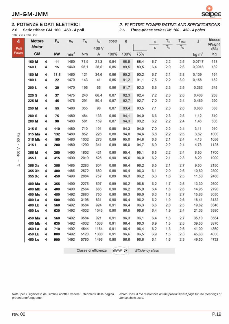
2.6. Three-phase series GM 160…450 - 4 poles
Note: Consult the references on the previous/next page for the meanings ofthe symbols used.
2.6. Serie trifase GM 160…450 - 4 poli
Nota: per il significato dei simboli adottati vedere i riferimenti della paginaprecedente/seguente.

JM-GM-JMM
rev. 00P.20
2. ELECTRIC POWER RATING AND SPECIFICATIONS2. POTENZE E DATI ELETTRICI
Tab. 2.7 / Tab. 2.7
Simboli - Symbols
PN = Potenza nominale - Rated power [kW] IN = Corrente nominale - Rated current [A]
nN = Velocità nominale - Rated speed [min-1] I S = Corrente di spunto - Breakaway starting current [A]
TN = Coppia nominale - Rated torque [Nm] cosϕ = Fattore di potenza nominale - Rated power factor
TS = Coppia di spunto - Starting torque [Nm] η = Rendimento ( Presa / Passorbita ) - Efficiency ( Pout / Pin )
Tmax = Coppia massima - Maximum torque [Nm] J = Momento d’inerzia - Moment of inertia [kg m2]
2.7. Three-phase series GM 160…450 - 6 poles2.7. Serie trifase GM 160…450 - 6 poli
rev. 00 P.21
JM-GM-JMM
2. ELECTRIC POWER RATING AND SPECIFICATIONS2. POTENZE E DATI ELETTRICI
Tab. 2.8 / Tab. 2.8
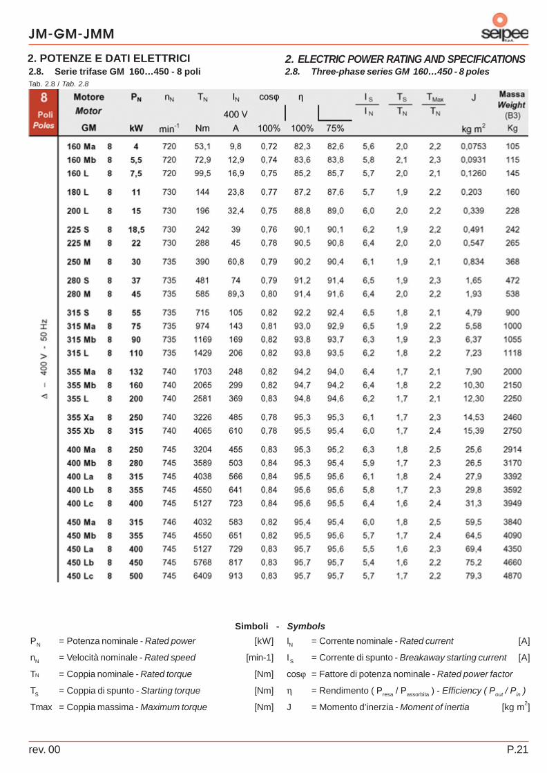
Simboli - Symbols
PN = Potenza nominale - Rated power [kW] IN = Corrente nominale - Rated current [A]
nN = Velocità nominale - Rated speed [min-1] I S = Corrente di spunto - Breakaway starting current [A]
TN = Coppia nominale - Rated torque [Nm] cosϕ = Fattore di potenza nominale - Rated power factor
TS = Coppia di spunto - Starting torque [Nm] η = Rendimento ( Presa / Passorbita ) - Efficiency ( Pout / Pin )
Tmax = Coppia massima - Maximum torque [Nm] J = Momento d’inerzia - Moment of inertia [kg m2]
2.8. Three-phase series GM 160…450 - 8 poles2.8. Serie trifase GM 160…450 - 8 poli

JM-GM-JMM
rev. 00P.22
2. ELECTRIC POWER RATING AND SPECIFICATIONS2. POTENZE E DATI ELETTRICI
Tab. 2.9 / Tab. 2.9
Simboli - Symbols
PN = Potenza nominale - Rated power [kW] IN = Corrente nominale - Rated current [A]
nN = Velocità nominale - Rated speed [min-1] I S = Corrente di spunto - Breakaway starting current [A]
TN = Coppia nominale - Rated torque [Nm] cosϕ = Fattore di potenza nominale - Rated power factor
TS = Coppia di spunto - Starting torque [Nm] η = Rendimento ( Presa / Passorbita ) - Efficiency ( Pout / Pin )
Tmax = Coppia massima - Maximum torque [Nm] J = Momento d’inerzia - Moment of inertia [kg m2]
2.9. Three-phase series JM-GM 80…315 - 2 polesINCREASED EFFICIENCY
2.9. Serie trifase JM-GM 80…315 - 2 poliEFFICIENZA AUMENTATA

rev. 00 P.23
JM-GM-JMM
2. ELECTRIC POWER RATING AND SPECIFICATIONS2. POTENZE E DATI ELETTRICI
Tab. 2.10 / Tab. 2.10
Simboli - Symbols
PN = Potenza nominale - Rated power [kW] IN = Corrente nominale - Rated current [A]
nN = Velocità nominale - Rated speed [min-1] I S = Corrente di spunto - Breakaway starting current [A]
TN = Coppia nominale - Rated torque [Nm] cosϕ = Fattore di potenza nominale - Rated power factor
TS = Coppia di spunto - Starting torque [Nm] η = Rendimento ( Presa / Passorbita ) - Efficiency ( Pout / Pin )
Tmax = Coppia massima - Maximum torque [Nm] J = Momento d’inerzia - Moment of inertia [kg m2]
2.10. Three-phase series JM-GM 80…315 - 4 polesINCREASED EFFICIENCY
2.10. Serie trifase JM-GM 80…315 - 4 poliEFFICIENZA AUMENTATA
JM-GM-JMM
rev. 00P.24
2. ELECTRIC POWER RATING AND SPECIFICATIONS2. POTENZE E DATI ELETTRICI
Tab. 2.11 / Tab. 2.11
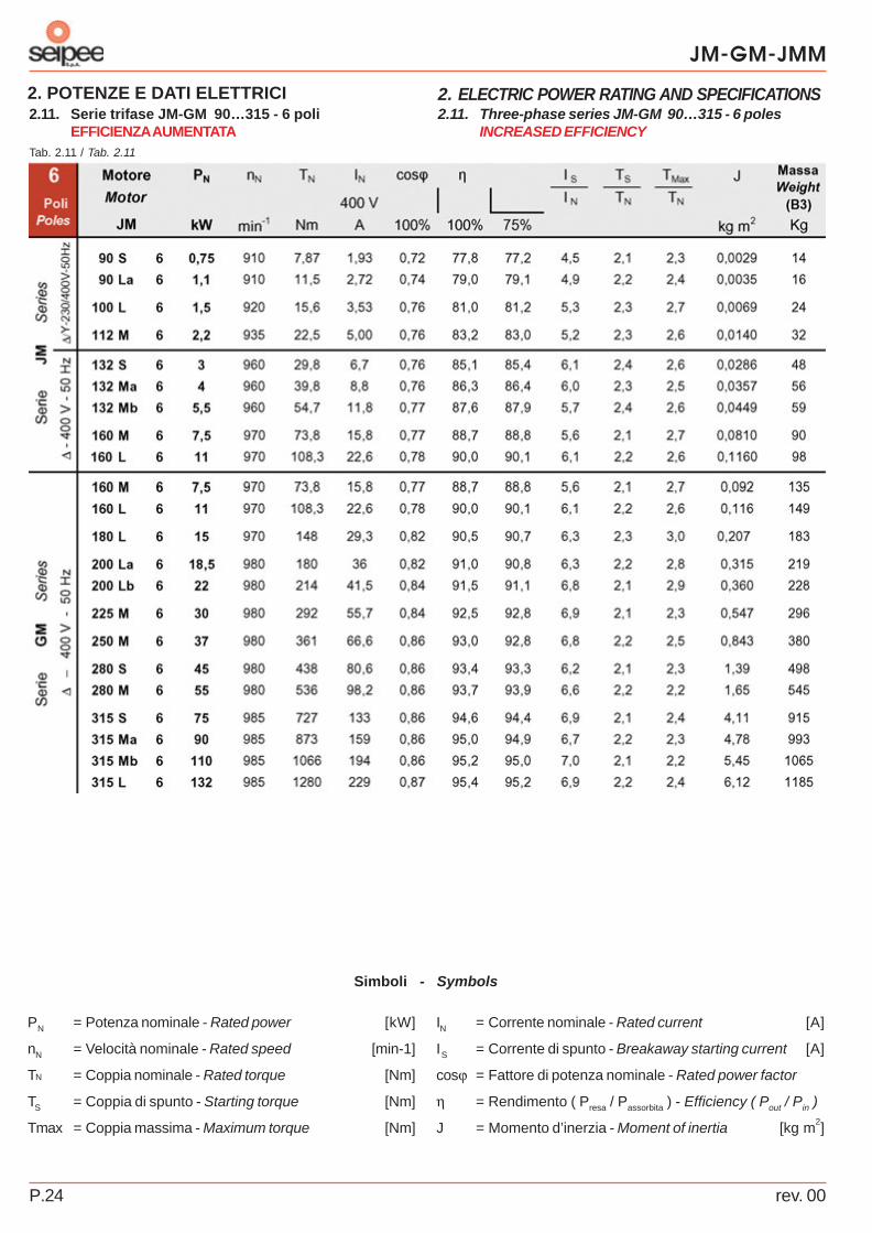
Simboli - Symbols
PN = Potenza nominale - Rated power [kW] IN = Corrente nominale - Rated current [A]
nN = Velocità nominale - Rated speed [min-1] I S = Corrente di spunto - Breakaway starting current [A]
TN = Coppia nominale - Rated torque [Nm] cosϕ = Fattore di potenza nominale - Rated power factor
TS = Coppia di spunto - Starting torque [Nm] η = Rendimento ( Presa / Passorbita ) - Efficiency ( Pout / Pin )
Tmax = Coppia massima - Maximum torque [Nm] J = Momento d’inerzia - Moment of inertia [kg m2]
2.11. Three-phase series JM-GM 90…315 - 6 polesINCREASED EFFICIENCY
2.11. Serie trifase JM-GM 90…315 - 6 poliEFFICIENZA AUMENTATA

rev. 00 P.25
JM-GM-JMM
2. ELECTRIC POWER RATING AND SPECIFICATIONS2. POTENZE E DATI ELETTRICI
Tab. 2.12 / Tab. 2.12
Tab. 2.13 / Tab. 2.13
Simboli - Symbols
PN = Potenza nominale - Rated power [kW] I S = Corrente di spunto - Breakaway starting current [A]
nN = Velocità nominale - Rated speed [min-1] cosϕ = Fattore di potenza nominale - Rated power factor
TN = Coppia nominale - Rated torque [Nm] η = Rendimento ( Presa / Passorbita ) - Efficiency ( Pout / Pin )
TS = Coppia di spunto - Starting torque [Nm] J = Momento d’inerzia - Moment of inertia [kg m2]
Tmax = Coppia massima - Maximum torque [Nm] C = Condensatore di marcia -Running capacitor [µF]
IN = Corrente nominale - Rated current [A] CE = Condensatore di avviamento - Starting capacitor [µF]
2.12. Single-phase series JMM 56…100 - 2 poles
2.13. Single-phase series JMM 56…100 - 4 poles
2) Auxiliary starting capacitor with electronic cutout: available on request (see“ Special mounting types …”).
2.12. Serie monofase JMM 56…100 - 2 poli
2.13. Serie monofase JMM 56…100 - 4 poli
2) Condensatore ausiliario di avviamento con disgiuntore elettronico:a richiesta (vedere “ Esecuzioni speciali …”).

JM-GM-JMM
rev. 00P.26
3. DIMENSIONS AND STANDARD VERSIONS3. DIMENSIONI E NORMALIZZATI
Forma costruttiva con flangiaFlange mounting
Forma costruttiva con piediStand mounting
IMB3
IMB5
IMB14
Estremità d’alberoShaft end
Fig. 3.1 / Draw. 3.1
3.1. Three-phase series JM 56…1603.1. Serie trifase JM 56…160
rev. 00 P.27
JM-GM-JMM
3. DIMENSIONS AND STANDARD VERSIONS3. DIMENSIONI E NORMALIZZATI
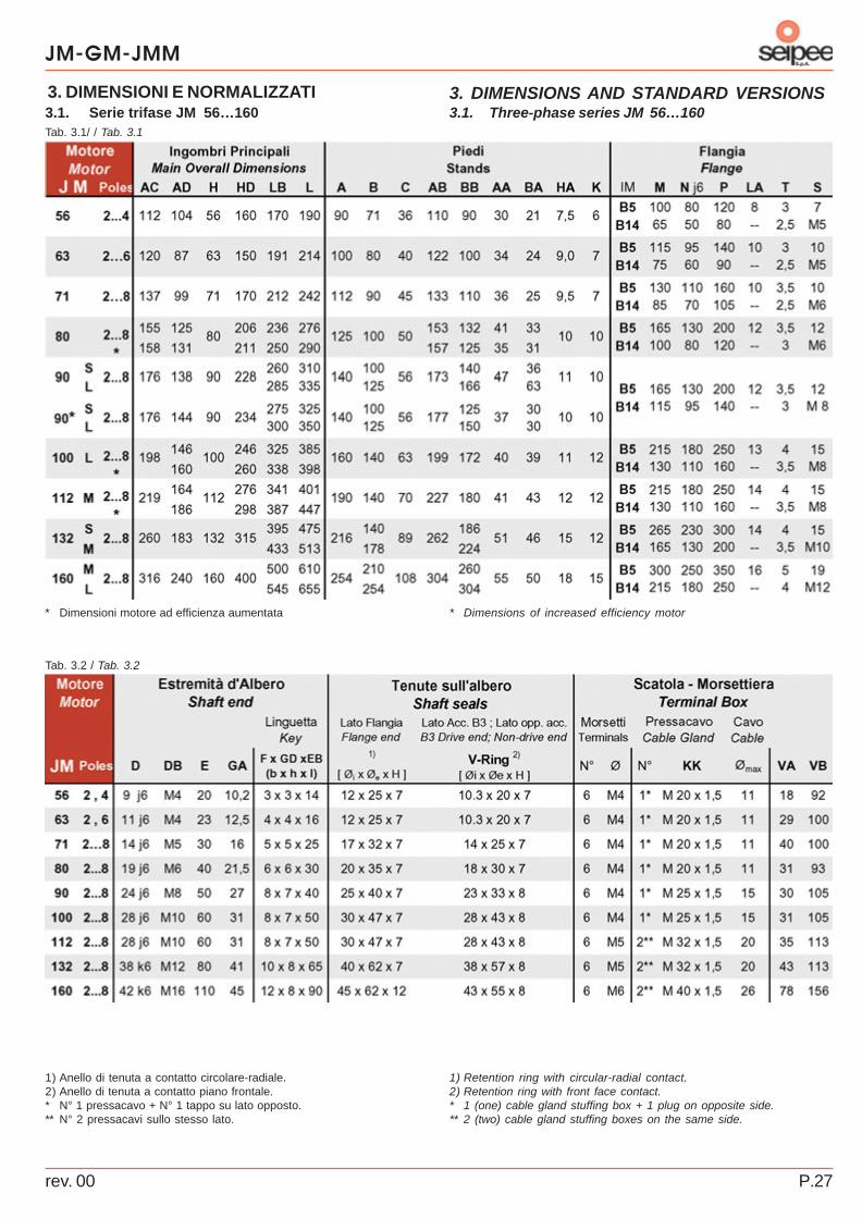
Tab. 3.1/ / Tab. 3.1
Tab. 3.2 / Tab. 3.2
* Dimensions of increased efficiency motor
1) Retention ring with circular-radial contact.2) Retention ring with front face contact.* 1 (one) cable gland stuffing box + 1 plug on opposite side.** 2 (two) cable gland stuffing boxes on the same side.
3.1. Three-phase series JM 56…160
* Dimensioni motore ad efficienza aumentata
1) Anello di tenuta a contatto circolare-radiale.2) Anello di tenuta a contatto piano frontale.* N° 1 pressacavo + N° 1 tappo su lato opposto.** N° 2 pressacavi sullo stesso lato.
3.1. Serie trifase JM 56…160

JM-GM-JMM
rev. 00P.28
3. DIMENSIONS AND STANDARD VERSIONS3. DIMENSIONI E NORMALIZZATI
Forma costruttiva con piediStand mounting
Fig. 3.2 / Draw. 3.2
3.2. Three-phase series GM 160…355
IMB3
IMB5
IMB14
Estremità d’alberoShaft end
Forma costruttiva con flangiaFlange mounting
3.2. Serie trifase GM 160…355
rev. 00 P.29
JM-GM-JMM
3. DIMENSIONS AND STANDARD VERSIONS3. DIMENSIONI E NORMALIZZATI
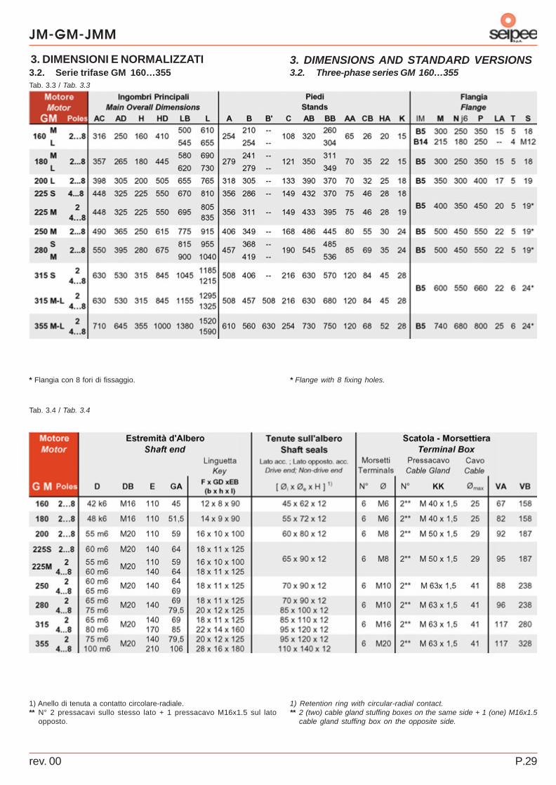
Tab. 3.3 / Tab. 3.3
Tab. 3.4 / Tab. 3.4
1) Retention ring with circular-radial contact.** 2 (two) cable gland stuffing boxes on the same side + 1 (one) M16x1.5
cable gland stuffing box on the opposite side.
3.2. Three-phase series GM 160…355
* Flange with 8 fixing holes.
1) Anello di tenuta a contatto circolare-radiale.** N° 2 pressacavi sullo stesso lato + 1 pressacavo M16x1.5 sul lato
opposto.
3.2. Serie trifase GM 160…355
* Flangia con 8 fori di fissaggio.

JM-GM-JMM
rev. 00P.30
3. DIMENSIONS AND STANDARD VERSIONS3. DIMENSIONI E NORMALIZZATI
IMB3
IMB5
Estremità d’alberoShaft end
Forma costruttiva con piediStand mounting
Forma costruttiva con flangiaFlange mounting
Tab. 3.5 / Tab. 3.5
Tab. 3.6 / Tab. 3.6
Fig. 3.3 / Draw. 3.3
3.3. Three-phase series GM 355X…450
1) Retention ring with circular-radial contact.
3.3. Serie trifase GM 355X…450
1) Anello di tenuta a contatto circolare-radiale.
rev. 00 P.31
JM-GM-JMM
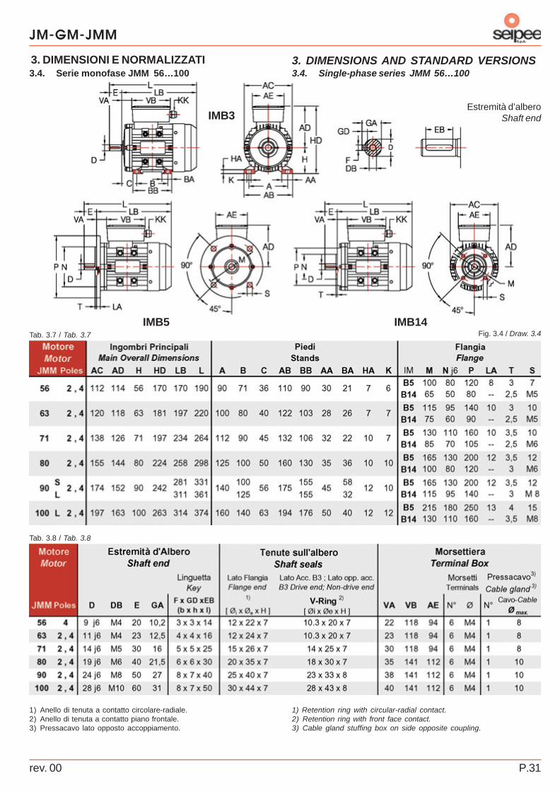
3. DIMENSIONS AND STANDARD VERSIONS3. DIMENSIONI E NORMALIZZATI
Tab. 3.8 / Tab. 3.8
Estremità d’alberoShaft endIMB3
Fig. 3.4 / Draw. 3.4IMB5 IMB14
Tab. 3.7 / Tab. 3.7
3.4. Single-phase series JMM 56…100
1) Retention ring with circular-radial contact.2) Retention ring with front face contact.3) Cable gland stuffing box on side opposite coupling.
3.4. Serie monofase JMM 56…100
1) Anello di tenuta a contatto circolare-radiale.2) Anello di tenuta a contatto piano frontale.3) Pressacavo lato opposto accoppiamento.
JM-GM-JMM
rev. 00P.32
4. SPECIAL MOUNTING TYPES AND ACCESSORIES4. ESECUZIONI SPECIALI E ACCESSORIE4.1. Mounting types
(1) Supplementary impregnation of winding. Consists of asecond impregnation cycle and is recommended:- when a superior protection for the winding is required- when there are electrical phenomena (voltage peaks)- when there are mechanical phenomena (induced
mechanical or electromagnetic vibrations)Designation on the motor: “Supplementary windingimpregnation”.(2) Condensation drain holes (GM 160…450, standardequipment on side opposite terminal box). Always specifythe motor’s operating position when ordering.(3) IP56 protection, standard supply with JM and GM series(cannot be supplied with mounting types/accessories N° (2),(15), (16).Recommended for motors that operate in very damp placesand/or when the motor is liable to be splashed with water.The protection degree on the data plate becomes IP56.Please contact us if vertical shaft motors are involved.(4) IP65 protection, with JM and GM series (cannot besupplied with mounting types/accessories N° (2), (15), (16).Recommended for motors that operate in dusty environments.The protection degree on the data plate becomes IP65. Please contact us if vertical shaft motors are involved.(5) Lateral terminal box for motors equipped with IM B3stands and deriving versions, as viewed from the controlside.(6) Motor without fan blowerMotor without fan and fan cover. Used in applications wherethe cooling action is provided by the external environment.Mounting type code on data plate “IC 418”.
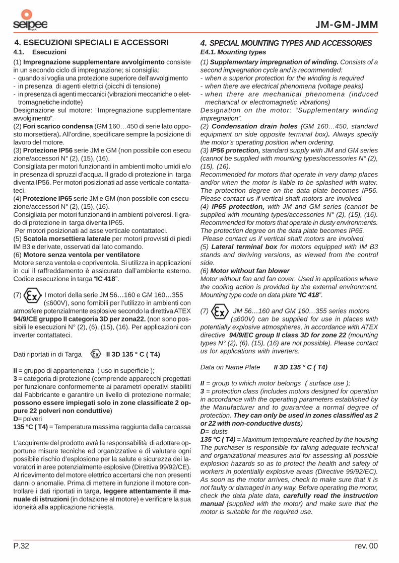
(7) JM 56…160 and GM 160…355 series motors(≤600V) can be supplied for use in places with
potentially explosive atmospheres, in accordance with ATEXdirective 94/9/EC group II class 3D for zone 22 (mountingtypes N° (2), (6), (15), (16) are not possible). Please contactus for applications with inverters.
Data on Name Plate II 3D 135 ° C ( T4)
II = group to which motor belongs ( surface use );3 = protection class (includes motors designed for operationin accordance with the operating parameters established bythe Manufacturer and to guarantee a normal degree ofprotection. They can only be used in zones classified as 2or 22 with non-conductive dusts)D= dusts135 °C ( T4) = Maximum temperature reached by the housingThe purchaser is responsible for taking adequate technicaland organizational measures and for assessing all possibleexplosion hazards so as to protect the health and safety ofworkers in potentially explosive areas (Directive 99/92/EC).As soon as the motor arrives, check to make sure that it isnot faulty or damaged in any way. Before operating the motor,check the data plate data, carefully read the instructionmanual (supplied with the motor) and make sure that themotor is suitable for the required use.
4.1. Esecuzioni
(1) Impregnazione supplementare avvolgimento consistein un secondo ciclo di impregnazione; si consiglia:- quando si voglia una protezione superiore dell’avvolgimento- in presenza di agenti elettrici (picchi di tensione)- in presenza di agenti meccanici (vibrazioni meccaniche o elet-
tromagnetiche indotte)Designazione sul motore: “Impregnazione supplementareavvolgimento”.(2) Fori scarico condensa (GM 160…450 di serie lato oppo-sto morsettiera). All’ordine, specificare sempre la posizione dilavoro del motore.(3) Protezione IP56 serie JM e GM (non possibile con esecuzione/accessori N° (2), (15), (16).Consigliata per motori funzionanti in ambienti molto umidi e/oin presenza di spruzzi d’acqua. Il grado di protezione in targadiventa IP56. Per motori posizionati ad asse verticale contatta-teci.(4) Protezione IP65 serie JM e GM (non possibile con esecu-zione/accessori N° (2), (15), (16).Consigliata per motori funzionanti in ambienti polverosi. Il gra-do di protezione in targa diventa IP65. Per motori posizionati ad asse verticale contattateci.(5) Scatola morsettiera laterale per motori provvisti di piediIM B3 e derivate, osservati dal lato comando.(6) Motore senza ventola per ventilatoreMotore senza ventola e copriventola. Si utilizza in applicazioniin cui il raffreddamento è assicurato dall’ambiente esterno.Codice esecuzione in targa “IC 418”.
(7) I motori della serie JM 56…160 e GM 160…355(≤600V), sono fornibili per l’utilizzo in ambienti con
atmosfere potenzialmente esplosive secondo la direttiva ATEX94/9/CE gruppo II categoria 3D per zona22. (non sono pos-sibili le esecuzioni N° (2), (6), (15), (16). Per applicazioni coninverter contattateci.
Dati riportati in di Targa II 3D 135 ° C ( T4)
II = gruppo di appartenenza ( uso in superficie );3 = categoria di protezione (comprende apparecchi progettatiper funzionare conformemente ai parametri operativi stabilitidal Fabbricante e garantire un livello di protezione normale;possono essere impiegati solo in zone classificate 2 op-pure 22 polveri non conduttive)D= polveri135 °C ( T4) = Temperatura massima raggiunta dalla carcassa
L’acquirente del prodotto avrà la responsabilità di adottare op-portune misure tecniche ed organizzative e di valutare ognipossibile rischio d’esplosione per la salute e sicurezza dei la-voratori in aree potenzialmente esplosive (Direttiva 99/92/CE).Al ricevimento del motore elettrico accertarsi che non presentidanni o anomalie. Prima di mettere in funzione il motore con-trollare i dati riportati in targa, leggere attentamente il ma-nuale di istruzioni (in dotazione al motore) e verificare la suaidoneità alla applicazione richiesta.
rev. 00 P.33
JM-GM-JMM
4. SPECIAL MOUNTING TYPES AND ACCESSORIES4. ESECUZIONI SPECIALI E ACCESSORI(8) Electrically insulated bearingThe rolling bearings of electric motors are potentially subjectto passing current, which rapidly damages the surfaces of thetracks and rolling bodies, and degrades the grease. There isa greater risk of damage in the increasingly more popularelectric motors equipped with frequency converters,especially in applications with repeated frequency variations.There is a further risk in the bearings of these motors, dueto the presence of currents at high frequency caused by thestray capacitance in the motor. The external surface of theouter ring of an electrically insulated bearing is coated with alayer of 100 µ thick aluminium oxide able to withstand avoltage of 1,000 V d.c.. It practically does away with the faultscaused by passing current. To be used in motors withfrequency converters: recommended from size 250onwards.
Miscellaneous- Special coatings- Fan cover for textile environment (JM 56…160).- Motors wound for voltage and frequency values differing from
the envisaged types of power supply.- Straight roller bearings for high radial loads (GM 160…280, 4,
6, 8 poles).
4.2. Accessories
(9) Bimetallic thermal probes (standard equipment with JM160 and GM 160…450). Characteristics: V
N,max. 250 [V], I
N,max.
1.6 [A]. Three probes connected in series with normally closedcontact installed in the motor winding. The contact opens whenthe temperature of the winding reaches and exceeds theoperating value. Terminals installed inside the motor’s terminalbox. Designation on the motor: “Bimetallic thermal probes”.(10) PTC thermistor probes (standard equipment with GM160…450). Conform to standard DIN 44081/44082. Threethermistors connected in series and installed in the winding.Must be connected to a dedicated release (the purchaser ofthe motor is responsible for buying this equipment). There is arepeated variation in resistance (which causes the releasingaction) when the temperature of the winding reaches andexceeds the operating value. Terminals installed inside themotor’s terminal box. Designation on the motor: “PTC thermistorprobes”.(11) PT 100 temperature sensor (resistance thermometer). Iscomply with standard DIN-IEC 751. This temperature sensortakes advantage of the way the resistivity of certain materialsvaries as the temperature changes. It must be connected to adedicated device (the purchaser of the motor is responsible forbuying this device).Winding: three PT 100 installed in the winding, one per phase.Terminals installed inside the motor’s terminal box.Bearings: a PT 100 installed in the bearing support (controlside, side opposite control). Terminals installed inside a switchbox enbloc with the motor housing.Designation on the motor: “PT 100 temperature sensor”.
(8) Cuscinetto isolato elettricamenteI cuscinetti volventi dei motori elettrici, sono potenzialmentesoggetti ai passaggi di corrente, che ne danneggiano rapida-mente le superfici delle piste e dei corpi volventi e ne degrada-no il grasso. Il rischio di danneggiamento aumenta nei semprepiù diffusi motori elettrici dotati di convertitori di frequenza, so-prattutto in applicazioni con repentine variazioni di frequenza.Nei cuscinetti di tali motori, c’è un ulteriore rischio dovuto allapresenza delle correnti di alta frequenza causate dalle capaci-tà parassite esistenti all’interno del motore. Il cuscinetto isola-to elettricamente ha la superficie esterna dell’anello esternorivestita con uno strato di ossido di alluminio spesso 100 µ, ingrado di resistere a tensioni di 1.000 V c.c.; elimina pratica-mente gli inconvenienti dovuti ai passaggi di corrente. Da utiliz-zare nei motori dotati di convertitori di frequenza: consigliatodalla grandezza 250.
Varie- Verniciature speciali- Copriventola per ambiente tessile (JM 56…160).- Motori avvolti per tensioni e frequenze diverse dai tipi di ali-
mentazione previsti.- Cuscinetto a rulli cilindrici per forti carichi radiali (GM 160…280,
4, 6, 8 poli).
4.2. Accessori
(9) Sonde termiche bimetalliche (JM 160 e GM 160…450 diserie). Caratteristiche: V
N,max. 250 [V], I
N,max. 1.6 [A]. Tre sonde
collegate in serie con contatto normalmente chiuso inseritenell’avvolgimento del motore. Si ha l’apertura del contatto quan-do la temperatura dell’avvolgimento raggiunge e supera il valo-re di intervento. Terminali posti all’interno della scatolamorsettiera motore. Designazione sul motore: “Sonde termi-che bimetalliche”.(10) Sonde termiche a termistori PTC (GM 160…450 di se-rie). Conformi alle norme DIN 44081/44082. Tre termistori col-legati in serie inseriti nell’avvolgimento, da collegare ad unaapposita apparecchiatura di sgancio (l’acquisto di tale appa-recchiatura è a carico dell’acquirente del motore). Si ha unarepentina variazione di resistenza (che provoca lo sgancio)quando la temperatura dell’avvolgimento raggiunge e supera ilvalore di intervento. Terminali posti all’interno della scatolamorsettiera motore. Designazione sul motore: “Sonde termi-che a termistori PTC”.(11) Sensore di temperatura PT 100 (termometro a resisten-za). Conformi alle norme DIN-IEC 751. È un sensore di tempe-ratura che sfrutta la variazione della resistività di alcuni mate-riali al variare della temperatura. Vanno collegati ad una appo-sita apparecchiatura (l’acquisto di tale apparecchiatura è a ca-rico dell’acquirente del motore).Avvolgimento: tre PT 100 inseriti nell’avvolgimento uno perfase. Terminali posti all’interno della scatola morsettiera motore.Cuscinetti: un PT 100 inserito nel supporto cuscinetto (latocomando, lato opposto comando). Terminali posti all’interno diuna scatola di derivazione solidale alla carcassa del motore.Designazione sul motore: “Sensore di temperatura PT 100”.
JM-GM-JMM
rev. 00P.34
4. SPECIAL MOUNTING TYPES AND ACCESSORIES4. ESECUZIONI SPECIALI E ACCESSORI
Tab. 4.1 / Tab. 4.1
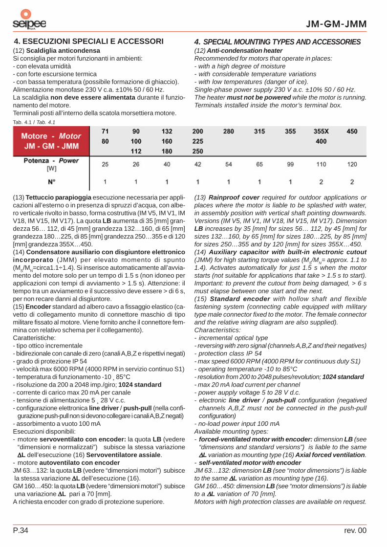
(12) Anti-condensation heaterRecommended for motors that operate in places:- with a high degree of moisture- with considerable temperature variations- with low temperatures (danger of ice).Single-phase power supply 230 V a.c. ±10% 50 / 60 Hz.The heater must not be powered while the motor is running.Terminals installed inside the motor’s terminal box.
(13) Rainproof cover required for outdoor applications orplaces where the motor is liable to be splashed with water,in assembly position with vertical shaft pointing downwards.Versions (IM V5, IM V1, IM V18, IM V15, IM V17). DimensionLB increases by 35 [mm] for sizes 56… 112, by 45 [mm] forsizes 132…160, by 65 [mm] for sizes 180…225, by 85 [mm]for sizes 250…355 and by 120 [mm] for sizes 355X…450.(14) Auxiliary capacitor with built-in electronic cutout(JMM) for high starting torque values (M
S/M
N= approx. 1.1 to
1.4). Activates automatically for just 1.5 s when the motorstarts (not suitable for applications that take > 1.5 s to start).Important: to prevent the cutout from being damaged, > 6 smust elapse between one start and the next.(15) Standard encoder with hollow shaft and flexiblefastening system (connecting cable equipped with militarytype male connector fixed to the motor. The female connectorand the relative wiring diagram are also supplied).Characteristics:- incremental optical type- reversing with zero signal (channels A,B,Z and their negatives)- protection class IP 54- max speed 6000 RPM (4000 RPM for continuous duty S1)- operating temperature -10 to 85°C- resolution from 200 to 2048 pulses/revolution; 1024 standard- max 20 mA load current per channel- power aupply voltage 5 to 28 V d.c.- electronic line driver / push-pull configuration (negatived
channels A,B,Z must not be connected in the push-pullconfiguration)
- no-load power input 100 mAAvailable mounting types:- forced-ventilated motor with encoder: dimension LB (see
“dimensions and standard versions”) is liable to the same∆∆∆∆∆L variation as mounting type (16) Axial forced ventilation.
- self-ventilated motor with encoderJM 63…132: dimension LB (see “motor dimensions”) is liableto the same ∆∆∆∆∆L variation as mounting type (16).GM 160…450: dimension LB (see “motor dimensions”) is liableto a ∆∆∆∆∆L variation of 70 [mm].Motors with high protection classes are available on request.
(12) Scaldiglia anticondensaSi consiglia per motori funzionanti in ambienti:- con elevata umidità- con forte escursione termica- con bassa temperatura (possibile formazione di ghiaccio).Alimentazione monofase 230 V c.a. ±10% 50 / 60 Hz.La scaldiglia non deve essere alimentata durante il funzio-namento del motore.Terminali posti all’interno della scatola morsettiera motore.
(13) Tettuccio parapioggia esecuzione necessaria per appli-cazioni all’esterno o in presenza di spruzzi d’acqua, con albe-ro verticale rivolto in basso, forma costruttiva (IM V5, IM V1, IMV18, IM V15, IM V17). La quota LB aumenta di 35 [mm] gran-dezza 56… 112, di 45 [mm] grandezza 132…160, di 65 [mm]grandezza 180…225, di 85 [mm] grandezza 250…355 e di 120[mm] grandezza 355X…450.(14) Condensatore ausiliario con disgiuntore elettronicoincorporato (JMM) per elevato momento di spunto(M
S/M
N=circa1.1÷1.4). Si inserisce automaticamente all’avvia-
mento del motore solo per un tempo di 1.5 s (non idoneo perapplicazioni con tempi di avviamento > 1.5 s). Attenzione: iltempo tra un avviamento e il successivo deve essere > di 6 s,per non recare danni al disgiuntore.(15) Encoder standard ad albero cavo a fissaggio elastico (ca-vetto di collegamento munito di connettore maschio di tipomilitare fissato al motore. Viene fornito anche il connettore fem-mina con relativo schema per il collegamento).Caratteristiche:- tipo ottico incrementale- bidirezionale con canale di zero (canali A,B,Z e rispettivi negati)- grado di protezione IP 54- velocità max 6000 RPM (4000 RPM in servizio continuo S1)- temperatura di funzionamento -10 ̧ 85°C- risoluzione da 200 a 2048 imp./giro; 1024 standard- corrente di carico max 20 mA per canale- tensione di alimentazione 5 ¸ 28 V c.c.- configurazione elettronica line driver / push-pull (nella confi-
gurazione push-pull non si devono collegare i canali A,B,Z negati)- assorbimento a vuoto 100 mAEsecuzioni disponibili:- motore servoventilato con encoder: la quota LB (vedere
“dimensioni e normalizzati”) subisce la stessa variazione∆∆∆∆∆L dell’esecuzione (16) Servoventilatore assiale.
- motore autoventilato con encoderJM 63…132: la quota LB (vedere “dimensioni motori”) subisce la stessa variazione ∆∆∆∆∆L dell’esecuzione (16).GM 160…450: la quota LB (vedere “dimensioni motori”) subisce una variazione ∆∆∆∆∆L pari a 70 [mm].A richiesta encoder con grado di protezione superiore.
rev. 00 P.35
JM-GM-JMM
4. SPECIAL MOUNTING TYPES AND ACCESSORIES4. ESECUZIONI SPECIALI E ACCESSORI
Tab. 4.2 / Tab. 4.2
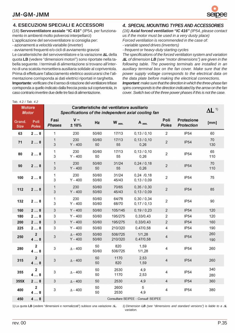
(16) Axial forced ventilation “IC 416” (IP54, please contactus if the motor must be used in a very dusty place)Forced ventilation is recommended in the case of:- variable speed drives (inverters)- frequent or heavy-duty starting cyclesThe specifications of the forced ventilation system and variation∆∆∆∆∆L of dimension LB (see “motor dimensions”) are given in thefollowing table. The powering terminals are installed in anauxiliary terminal box on the fan cover. Make sure that thepower supply voltage corresponds to the electrical data onthe data plate before making the electrical connections.Important: make sure that the direction in which the three-phase fanspins corresponds to the direction indicated by the arrow on the fancover. Switch two of the three power phases if this is not the case.
1) Dimension LB (see “dimensions and standard versions”) is liable to a ∆Lvariation.
(16) Servoventilatore assiale “IC 416” (IP54, per funziona-mento in ambienti molto polverosi interpellarci)L’applicazione del servoventilatore si consiglia per:- azionamenti a velocità variabile (inverter)- avviamenti frequenti e/o cicli di avviamento gravosiLe caratteristiche del servoventilatore e la variazione ∆∆∆∆∆L dellaquota LB (vedere “dimensioni motori”) sono riportate nella ta-bella seguente. I terminali di alimentazione si trovano all’inter-no di una scatola morsettiera ausiliaria solidale al copriventola.Prima di effettuare l’allacciamento elettrico assicurarsi che l’ali-mentazione corrisponda ai dati elettrici riportati in targhetta.Importante: verificare che il senso di rotazione del ventilatore trifasecorrisponda a quello indicato dalla freccia posta sul copriventola, incaso contrario invertire due delle tre fasi di alimentazione.
1) La quota LB (vedere “dimensioni e normalizzati”) subisce una variazione ∆L.

JM-GM-JMM
rev. 00P.36
5. INSTALLATION AND MAINTENANCE5. INSTALLAZIONE E MANUTENZIONE5.1. General recommendations
Disassembly of the motor or replacement of its partsautomatically voids the warranty with which the purchasedmotor is provided.
Please note that the motors in this catalogue are comply of thefollowing Community Directives:
- “Low Voltage” Directive 2006/95/EEC”. The motors inthis catalogue are comply of the directive and bear the CEmark on the data plate.
- “Electromagnetic Compatibility” Directive 2004/108/EEC.Not obligatorily applicable to the products in this catalogue.The machine manufacturer is responsible for compliancewith the directive.
Safety: improper use of the motor, incorrect installation,removal of the protections, elimination of the safety devicesand negligent maintenance may cause serious damage topersons and things. Thus, the motor must only be handled,installed, commissioned, serviced and repaired by qualifiedpersonnel (in accordance with IEC364).
Dangers: electric motors have live parts, moving parts andparts that reach temperatures exceeding 50°C. All work onthe motor must be performed when the motor itself is at astandstill and disconnected from the mains power supply.Disconnect any auxiliary equipment and take all measuresto prevent sudden starts. The capacitor of single-phasemotors may remain loaded, thus keeping the motor’s terminalbox live.
5.2. Arrival of motor and installationArrival: make sure that the motor is the same as the oneordered and that it has sustained no damage during transport.A damaged motor cannot be used. The eyebolts on thehousing are designed for lifting the motor alone. If the motormust be kept in stock, store it in a sheltered, clean, dryplace free from vibrations and corrosive agents. If the motoris to be stored or remain idle for a long period of time, it isadvisable to check the insulation resistance between thewindings and towards earth with the relative instrument.Please contact us if the motor must operate at a differenttemperature from -15 +40 °C or at an altitude of more than1,000 m. It is forbidden to use the motor in places with anaggressive atmosphere, where there is a risk of explosion.
Installation : the motor must be positioned so that air is freeto pass around the fan side. Insufficient air circulation willobstruct the heat exchange. Do not install the motor nearother heat sources that could affect the temperature of boththe cooling air and the motor itself. Holes for draining offcondensation must point downwards, so as to allow the fluidto flow out.
5.1. Avvertenze generali
La garanzia sul motore acquistato viene automaticamen-te a decadere qualora il motore subisca lo smontaggio ela sostituzione di parti.
Ricordiamo che i motori del presente catalogo sono conformialle seguenti Direttive Comunitarie:
- Direttiva “Bassa Tensione” 2006/95/CEE”. I motori del pre-sente catalogo sono conformi alla direttiva e riportano in targail marchio CE.
- Direttiva “Compatibilità Elettromagnetica” 2004/108/CEE.Non obbligatoriamente applicabile ai prodotti di questo catalo-go. La responsabilità della conformità alla direttiva è a caricodel costruttore della macchina.
Sicurezza: un uso improprio del motore, un’installazio-ne non corretta, la rimozione delle protezioni, l’elimina-zione dei dispositivi di sicurezza, la carenza di manuten-zione, possono causare gravi danni a persone e cose.Pertanto deve essere movimentato, installato, messo in servi-zio, curato e riparato esclusivamente da personale qualificato(secondo IEC364).
Pericoli: motori elettrici presentano parti poste sotto tensio-ne, parti in movimento, parti con temperature superiori a 50°C.Qualsiasi intervento sul motore deve avvenire sempre quando èfermo e scollegato dalla rete di alimentazione. Scollegare even-tuali equipaggiamenti ausiliari e eliminare ogni possibilità diavviamento improvviso. Nei motori monofase il condensatoredi esercizio può rimanere carico, mantenendo sotto tensionela morsettiera motore.
5.2. Ricevimento e installazioneRicevimento: verificare che il motore corrisponda a quantoordinato e che non abbia subito danneggiamenti durante il tra-sporto. Non si può mettere in servizio un motore danneggiato.I golfari eventualmente presenti nella carcassa servono al sol-levamento del solo motore. Per l’eventuale giacenza in ma-gazzino, il luogo deve essere coperto, pulito, asciutto, privo divibrazioni e agenti corrosivi. Dopo lunghi periodi di giacenza amagazzino o lunghi periodi di inattività, si consiglia di verificarela resistenza di isolamento tra gli avvolgimenti e verso mas-sa con apposito strumento. Per funzionamenti con temperatu-ra diversa da -15 +40 °C e ad altitudini superiori ai 1.000 m,interpellateci. Non è consentito l’impiego in luoghi conatmosfere aggressive, con pericolo di esplosione.
Installazione : sistemare il motore in modo che si abbia unampio passaggio d’aria dal lato della ventola; insufficiente cir-colazione d’ aria compromette lo scambio termico. Evitare lavicinanza con altre fonti di calore tali da influenzare la tempera-tura sia dell’aria di raffreddamento che del motore perirraggiamento. Eventuali fori scarico condensa devono esse-re rivolti verso il basso, per permettere lo scarico. Quando èpossibile proteggere il motore: dall’eccessivo irraggiamento so-lare (la temperatura del motore potrebbe aumentare eccessi-vamente), dalle intemperie (IM V1 e derivate è necessario ri-
rev. 00 P.37
JM-GM-JMM
5. INSTALLATION AND MAINTENANCE5. INSTALLAZIONE E MANUTENZIONEWhen possible, protect the motor against: excessive exposureto the sun (the temperature of the motor could increase toomuch), inclement weather (order the motor with the rainproofcover when IM V1 and deriving versions are required) andsplashing water (seal the terminal box and cable inlet withsealing cement). Foundation: must be well-sized to ensurethat the assembly is stable. Couplings: make sure that theradial/axial load is within the values given in Tab. 1.5 and Tab.1.6. Tolerance H7 is recommended for the hole of the partskeyed to the end of the shaft . Clean and lubricate the surfacesbefore coupling so as to prevent seizures. Always use the rela-tive jacking screws (pullers) during the assembly anddisassembly operations so as to prevent the motor bearingsfrom being damaged. Never use a hammer or mallet. Jointsand pulleys should be heated to 60-80°C prior to assembly.Direct coupling: make sure that the drive shaft is aligned withthat of the driven machine. Belt drives: make sure that theshaft of the motor is parallel to the shaft of the driven machine,that the pulley overhangs to the smallest possible extent andthat the belt tension is unable to impair the life of the bearingsor break the drive shaft. The motors are balanced with a half-key. To prevent vibrations or imbalances, the transmissioncomponents must be correctly balanced before they arecoupled. For duty with a high number of starts, the motor mustbe protected against excessive heating by means of a thermalprotection (bimetallic, PTC thermistor, PT100). Amagnetothermal circuit-breaker is not enough. The low-voltagestarting method can be used to obtain smooth starts at lowbreakaway starting current values (use Y / ∆∆∆∆∆ or soft startersfor no load starts or with reduced loads and use an inverter forfull-load starts or applications with high moments of inertia).Operation with inverters: JM and GM motors are suitable foroperation with inverters (limit values: power-supply voltage U
N
< 500 V, voltage peaks Umax
< 1000 V, voltage gradients dU/dt< 1kV/µs. Contact us for > 500 V power supply voltage values.Use of inverters requires the following precautions: The entityof these peaks/gradients is bound to the inverter’s power-supplyvoltage and the length of the motor’s feeder cables. To limitthis entity, it is advisable to use special filters (at the purchaser’scharge) installed between the inverter and motor (obligatory for> 30 m feeder cables).ATEX 94/9/EC group II class 3D motors for zone 22: Thepurchaser is responsible for taking adequate technical andorganizational measures and for assessing all possibleexplosion hazards so as to protect the health and safety ofworkers in potentially explosive areas (Directive 99/92/EC). Assoon as the motor arrives, check to make sure that it is notfaulty or damaged in any way. Before operating the motor, checkthe data plate data, carefully read the instruction manual(supplied with the motor) and make sure that the motor issuitable for the required use. Please contact us if theapplications is to be used with an inverter.
chiedere il motore con il tettuccio para-pioggia) e da spruzzid’acqua (sigillare la scatola morsettiera e l’entrata cavo conmastice da guarnizione). Fondazione: deve essere bendimensionata per garantire stabilità al fissaggio. Accoppia-menti: verificare che il carico radiale/assiale rientri nei valoririportati in Tab. 1.5 e Tab. 1.6. 0Per il foro degli organi calettatisull’estremità dell’albero è consigliata la tolleranza H7. Primadi eseguire l’accoppiamento pulire e lubrificare le superfici dicontatto per evitare pericoli di grippaggio. Nelle operazioni dimontaggio (smontaggio) utilizzare sempre appositi tiranti(estrattori) per evitare eventuali danni ai cuscinetti del motore.L’uso del martello è quindi da escludere. È consigliabile riscal-dare eventuali giunti, pulegge fino a 60-80 °C prima del mon-taggio. Accoppiamento diretto: curare l’allineamento del mo-tore rispetto a quello della macchina condotta. Accoppiamentoa cinghia: verificare che l’asse del motore sia sempre paralle-lo all’asse della macchina condotta, lo sbalzo della puleggiadeve essere il minimo possibile, la tensione delle cinghie nondeve essere eccessiva per non compromettere la durata deicuscinetti o provocare la rottura dell’albero motore. I motorisono equilibrati con mezza linguetta; per evitare vibrazioni esquilibri è necessario che gli organi di trasmissione siano statiopportunamente equilibrati prima dell’accoppiamento. Per ser-vizi con elevato numero di avviamenti è necessario proteggereil motore per evitare un surriscaldamento eccessivo, utilizzan-do una protezione termica (bimetallica, termistore PTC, PT100);l’interruttore magnetotermico non è sufficiente. Per ottenereavviamenti dolci con basse correnti di spunto si può adottarel’avviamento a tensione ridotta (per partenze a vuoto o con ca-richi ridotti utilizzare l’avviamento Y / ∆∆∆∆∆ o con soft starters,mentre per avviamenti a pieno carico e nelle applicazioni conelevati momenti d’inerzia, utilizzare l’inverter).Funzionamento con inverter: i motori JM e GM, sono adattial funzionamento con inverter (valori limiti: tensione alimenta-zione U
N < 500 V, picchi di tensione U
max < 1000 V, gradienti di
tensione dU/dt < 1kV/µs. Per tensione di alimentazione > 500V interpellarci. L’utilizzo dell’inverter richiede delle precauzioni:l’entità di tali picchi/gradienti è legata al valore della tensione dialimentazione dell’inverter e alla lunghezza dei cavi di alimen-tazione del motore. Per limitare tale entità si consiglia l’utilizzodi appositi filtri (a cura dell’acquirente) posti tra inverter e moto-re (obbligatori per cavi di alimentazione > di 30 m).Motori ATEX 94/9/CE gruppo II categoria 3D per zona 22:l’acquirente del prodotto avrà la responsabilità di adottare op-portune misure tecniche ed organizzative e di valutare ognipossibile rischio d’esplosione per la salute e sicurezza dei la-voratori in aree potenzialmente esplosive (Direttiva 99/92/CE).Al ricevimento del motore elettrico accertarsi che non presentidanni o anomalie. Prima di mettere in funzione il motore con-trollare i dati riportati in targa, leggere attentamente il ma-nuale di istruzioni (in dotazione al motore) e verificare la suaidoneità alla applicazione richiesta. Nel caso di applicazionicon inverter interpellarci.

JM-GM-JMM
rev. 00P.38
5. INSTALLATION AND MAINTENANCE5. INSTALLAZIONE E MANUTENZIONE
Fig. 5.1 / Draw. 5.1
Fig. 5.2 / Draw. 5.2
5.3. Connections
Motor connection
Make sure that the power supply voltage corresponds tothe electrical data on the data plate before making theelectrical connections. Make the connections as indicatedin the wiring diagrams on the sheet inside the terminal box.Use cables with adequate sections to prevent overheating orexcessive voltage drops on the motor’s terminals.
Three-phase motor: pay attention to the connection in theterminal box and to the one shown on the motor’s data plate.The minimum voltage refers to the ∆∆∆∆∆ connection, themaximum voltage to the Y connection. Star-delta startingcan only be obtained when the mains voltage corresponds tothe value of ∆∆∆∆∆.
Direction of rotation: it is advisable to check the motor’sdirection of rotation before it is coupled to the usermachine.The wrong direction of rotation could cause damageto persons and things (you are advised to remove the splinefrom the end of the shaft to prevent it from springing out in aviolent manner). To change the direction of rotation of a three-phase motor, just switch two of the mains power phases whilein single-phase motors, you must change the positions of thejumpers in the terminal box (comply with the wiring diagraminside the terminal box cover).
Three-phase single polarity wiring diagram
Single-phase wiring diagram
5.3. Collegamenti
Collegamento motore
Prima di effettuare l’allacciamento elettrico assicurarsiche l’alimentazione corrisponda ai dati elettrici riportatiin targa. Eseguire il collegamento secondo gli schemi indicatinel foglio contenuto all’interno della scatola morsettiera. Utiliz-zare cavi di sezione adeguata in modo da evitare unsurriscaldamento e/o eccessiva caduta di tensione ai morsettidel motore.
Motore trifase: fare attenzione al collegamento esistente inmorsettiera e a quello riportato sulla targa del motore; il voltag-gio minimo è riferito al collegamento a ∆∆∆∆∆, il voltaggio massimoa Y. L’avviamento stella-triangolo è possibile solo quando latensione di rete corrisponde al valore a ∆∆∆∆∆.
Senso di rotazione: è consigliabile verificare il senso di rota-zione del motore prima dell’accoppiamento alla macchinautilizzatrice, quando un senso di rotazione contrario a quellodesiderato può causare danni a persone e/o cose (si consigliadi togliere la linguetta dall’estremità dell’albero per evitare lasua violenta fuoriuscita). Per modificare il senso di rotazionenei motori trifasi è sufficiente invertire due fasi di alimentazionidella linea, mentre per i motori monofasi occorre cambiare ladisposizione dei ponticelli presenti in morsettiera (seguire loschema di collegamento presente sul lato interno delcoprimorsettiera).
Schema di collegamento trifase singola polarità
Schema di collegamento monofase
rev. 00 P.39
JM-GM-JMM
5. INSTALLATION AND MAINTENANCE5. INSTALLAZIONE E MANUTENZIONEEarth connection: metal parts of the motor that are normallynot live must be earthed by means of the relative terminal inthe terminal box (use a cable with an adequate section).
Connection of thermal protectionsTerminals installed inside the motor’s terminal box. Theseprotections require a dedicated relay or release device (at themotor purchaser’s charge). Check the specifications on thesticker that identifies the type of protection prior to connection.WARNING: failure to connect the thermal probes (whenapplicable) will void the warranty with which the motor isprovided.
Connection of the anti-condensation heaterTerminals installed inside the motor’s terminal box. Check thespecifications on the sticker that identifies the type of protectionprior to connection (check the power supply specifications).The heater must not be powered while the motor is running.
PT 100 temperature sensor connection(resistancethermometer). Comply of standard DIN-IEC 751. Check thespecifications on the sticker that identifies the type of protectionprior to connection. PT 100 sensors require a special device inorder to be used (at the motor purchaser’s charge).
Winding: three PT 100 installed in the winding, one per phase.Terminals installed inside the motor’s terminal box.Bearings: a PT 100 installed in the bearing support (controlside, side opposite control). Terminals installed inside a switchbox enbloc with the motor housing.
Connection of the forced axial fanThe powering terminals are installed in an auxiliary terminalbox on the fan cover. Check the specifications on theidentification sticker prior to connection (check the powersupply specifications).Important: make sure that the direction in which the three-phase fan spins corresponds to the direction indicated by thearrow on the fan cover. Switch two of the three power phases ifthis is not the case.
Encoder connectionConnection lead equipped with a military type male connectorfixed to the motor. The female connector and the relative wiringdiagram are also supplied). Check the specifications on theidentification sticker prior to connection.Recommendations for installation.- use shielded cables with earth connection. They must be
routed separately from the power cables- install the control board as near as possible to the encoder
and as far as possible from the inverter (when the invertercannot be shielded in an adequate way).
Messa a terra: le parti metalliche del motore che normalmen-te non sono sotto tensione devono essere collegate a terrautilizzando l’apposito morsetto contrassegnato, posto all’inter-no della scatola morsettiera (utilizzare un cavo di sezione ade-guata).
Collegamento protezioni termicheTerminali posti all’interno della scatola morsettiera motore. Leprotezioni necessitano di una apposito relè o apparecchiaturadi sgancio (a carico dell’acquirente del motore). Prima del col-legamento, verificare le caratteristiche riportate nella targhettaadesiva che identifica il tipo di protezione.ATTENZIONE: il mancato collegamento delle sonde ter-miche (quando presenti) comporta l’annullamento dellagaranzia del motore.
Collegamento scaldiglia anticondensaTerminali posti all’interno della scatola morsettiera motore. Pri-ma del collegamento verificare le caratteristiche riportate sullatarghetta adesiva che identifica il tipo di protezione (verificare idati di alimentazione). La scaldiglia non deve essere alimenta-ta durante il funzionamento del motore.
Collegamento sensore di temperatura PT 100 (termome-tro a resistenza). Conformi alle norme DIN-IEC 751. Prima delcollegamento verificare le caratteristiche riportate sella targhettaadesiva che identifica il tipo di protezione. I PT 100 necessita-no di una apposita apparecchiatura per essere utilizzati (a ca-rico dell’acquirente del motore).
Avvolgimento: tre PT 100 inseriti nell’avvolgimento uno perfase. Terminali posti all’interno della scatola morsettiera motore.Cuscinetti: un PT 100 inserito nel supporto cuscinetto (latocomando, lato opposto comando). Terminali posti all’interno diuna scatola di derivazione solidale alla carcassa del motore.
Collegamento servoventilatore assialeTerminali di alimentazione posti all’interno di una scatolamorsettiera ausiliaria solidale al copriventola. Prima del colle-gamento verificare le caratteristiche riportate sulla targhettaadesiva di identificazione (verificare i dati di alimentazione).Importante: verificare che il senso di rotazione del ventilatoretrifase corrisponda a quello indicato dalla freccia posta sulcopriventola, in caso contrario invertire due delle tre fasi di ali-mentazione.
Collegamento encoderCavetto di collegamento munito di connettore maschio di tipomilitare fissato al motore. Viene fornito anche il connettore fem-mina con relativo schema per il collegamento). Prima del colle-gamento verificare le caratteristiche riportate sulla targhettaadesiva di identificazione.Consigli utili all’installazione.- utilizzare cavi schermati con connessione a terra; devono
essere posizionati separatamente dai cavi di potenza- Installare la scheda di controllo il più vicino possibile all’encoder
e il più lontano possibile all’eventuale inverter (quando non èpossibile schermare in modo adeguato l’inverter).
JM-GM-JMM
rev. 00P.40
5. INSTALLATION AND MAINTENANCE5. INSTALLAZIONE E MANUTENZIONEImportant: once the connections have been made, check tomake sure that the electric terminals are well tightened, positionthe seal correctly and close the terminal box again. If the motoris installed in a place where it is frequently subjected tosplashing water, it is advisable to seal the terminal box andcable inlet with sealing cement.
5.4.Routine maintenance
To be carried out in conditions of total safety: motor at astandstill and disconnected from the mains power supply.
- Make sure that the entire cooling circuit (housing, air inletfrom the fan side and forced ventilation fan, if applicable)is free from dust, oil and any machining residue so as toprevent the motor from overheating and the normal coolingcycle from being impaired.
- Make sure that the motor operates without vibrations orabnormal noise. If vibrations are noted, check the motor’sfoundation and make sure that the machine to which themotor is connected is correctly balanced.
- Check the tension of any belts (excessively taut beltssensibly reduce the life of the motor’s bearings and cancause the shaft end to break).
- Check the condition of the shaft seals and grease themperiodically as these components function in contact withmoving parts and wear out very quickly. Once worn, theymust be replaced with components identical to the originalones.
- Check the condition of the bearings. The bearings installedin the JM and JMM series must be simply replaced at theend of their working life. The bearings installed in the GMseries need to be lubricated at regular intervals (thefrequency is indicated on the label on the motor). Bearinglife varies considerably and depends on the type of loadand number of starts to which the motor is subjected. Italso depends on the temperature and degree of humidity inthe work environment. Excessive noise usually means thatthe bearings need to be replaced. If the motor has beenrecently commissioned, the first thing to do is to check thecoupling (correct any alignment errors and check the tensionof any belts). If the bearings continue to be noisy it meansthat they are already damaged and must be replaced. Takegreat care to prevent the windings from being damagedwhen the bearings are being replaced and the shaft withrotor is removed from the stator. Use a press with anadequate sleeve resting on the inner ring when assemblingthe bearings, or preheat the bearing to a temperature ofabout 80°C and place it in its housing. Make sure that theinner rings rest correctly against the shaft supports andthat the replaced bearings are the same as the originalones or an equivalent type. It is always advisable to replacethe seals on the shaft.
Important: if motor components are disassembled or re-assembled in places where protective cement or silicone hasbeen applied, remember to guarantee the same degree ofprotection when the parts are re-assembled.
Importante: al termine dei collegamenti, verificare il correttoserraggio dei morsetti elettrici, posizionare correttamente la guar-nizione e richiudere la scatola morsettiera. Per installazioni inambienti con frequenti spruzzi d’acqua si consiglia di sigillare lascatola morsettiera e l’entrata cavi con mastice per guarnizioni.
5.4.Manutenzione periodica
Da effettuarsi in condizioni di totale sicurezza: motore fermo,scollegato dalla rete di alimentazione.
- Verificare che l’intero circuito di raffreddamento (car-cassa, entrata d’aria dal lato ventola, eventualeservoventilatore) sia esente da polvere, oli e da qualsiasi resi-duo di lavorazione in modo da evitare che il motore si surri-scaldi per l’impedimento del normale ciclo di raffreddamento.
- Controllare che il motore funzioni senza vibrazioni nérumori anomali. Se ci sono vibrazioni controllare la fonda-zione del motore e l’equilibratura della macchina accoppiata.
- Verificare la tensione di eventuali cinghie (una tensioneelevata riduce sensibilmente la durata dei cuscinetti del mo-tore, può causare anche la rottura dell’estremità dell’albero).
- Verificare lo stato delle tenute sull’albero ed ingrassarleperiodicamente perché tali componenti lavorano a contattocon le parti in movimento e si usurano velocemente. Unavolta usurate , vanno sostituite utilizzando componenti iden-tici agli originali.
- Verificare lo stato dei cuscinetti. I cuscinetti montati nellaserie JM e JMM vanno semplicemente sostituiti al terminedella loro vita. I cuscinetti montati nelle serie GM necessita-no di lubrificazione ad intervalli regolari (vedere etichetta sugliintervalli posta sul motore). La durata dei cuscinetti varia moltoa seconda dei tipi di carichi e di avviamenti che si applicanoal motore e dipende anche dalle temperature e dall’umiditàdell’ambiente di lavoro. L’eccessiva rumorosità indica di soli-to la necessità di sostituire i cuscinetti. Se la messa in fun-zione è stata realizzata da poco occorre innanzi tutto con-trollare l’accoppiamento (provvedere a correggere gli errori diallineamento o verificare la tensione delle eventuali cinghie).Se i cuscinetti continuano ad essere rumorosi, significa chesono già stati compromessi e occorre sostituirli. Durante lasostituzione dei cuscinetti, quando si estrae l’albero con ro-tore dallo statore, occorre fare molta attenzione a non dan-neggiare gli avvolgimenti. Per il montaggio dei cuscinetti uti-lizzare una pressa con adeguato manicotto appoggiato al-l’anello interno, oppure preriscaldare il cuscinetto stesso acirca 80 °C e porlo in sede. Assicurarsi che gli anelli internisiano correttamente appoggiati agli spallamenti dell’albero eche i cuscinetti sostituiti siano dello stesso tipo o equivalentia quelli originali. Si consiglia di sostituire sempre le tenutesull’albero.
Importante: in caso di smontaggio e rimontaggio di compo-nenti del motore ove sia presente mastice e/o silicone di pro-tezione, garantire lo stesso livello di protezione al momentodel ri-assemblaggio.

rev. 00 P.41
JM-GM-JMM
5. INSTALLATION AND MAINTENANCE5. INSTALLAZIONE E MANUTENZIONETab. 5.1 / Tab. 5.1
* Halve the quantity of grease on the side opposite the coupling.1) Valid for good quality lithium grease and operating temperatures of
not more than 90 °C, horizontal drive shaft and normal loads. Halve thevalues in the table for applications with a vertical drive shaft. If theoperating temperature exceeds 90°C: halve the values in the table forevery 15°C of temperature increase. (Maximum operating temperaturewith regard to Lithium grease with mineral based oil, i.e. about 100°C).
Procedure for re-lubricating non-shielded bearings:- If the bearings must be re-lubricated at intervals of less thanonce every six months (indicative frequency), all the grease muststill be completely replaced after 2 or 3 top-ups at most.- If the bearings must be re-lubricated at intervals of more thanonce every six months (indicative frequency), all the grease mustbe completely replaced every six months.When the old grease is replaced, it is advisable to remove allthe old grease and to re-lubricate the bearing by hand if thesupports are accessible. The vacant space inside the bearingmust be completely filled with fresh grease, while only 30 to50% of the space in the support must be filled. There must notbe too much grease in the space around the bearing as thiscould lead to a local temperature increase, which would ruinboth the grease and the bearing (take care to prevent dirt frombeing introduced into the bearing or support along with the grease).If the supports are inaccessible, the grease can be completelyreplaced by means of the lubricator. Unscrew the drain plug (inthe lower part of the support) and top up until all the old greasehas been pushed out. When possible, top up the grease whilstthe motor is running. This operation must always be carried outin safe conditions, to prevent the support from being filled withtoo much grease. The fill plug can be tightened on once a balancedtemperature has been obtained. It is advisable to install automaticsystems to simplify the operation if the bearings must belubricated very frequently. Regular lubrication is essential forbearing life and, thus, for the operation of the motor itself. Alwaysuse good quality mineral oil based Lithium grease.
* Dimezzare la quantità di grasso lato opposto accoppiamento.1) Valido per grassi al litio di buona qualità e temperature di lavoro non
superiori a 90 °C, albero-motore orizzontale e carichi normali. Dimezzarei valori di tabella per applicazioni con albero-motore verticale. Pertemperature di lavoro superiori ai 90 °C: dimezzare i valori di tabella perogni 15 °C di aumento di temperatura. (Temperatura massima di lavoro,relativa a grasso al Litio con olio di base minerale, pari a circa 110 °C).
Procedimenti per la rilubrificazione dei cuscinetti nonschermati:- Se l’intervallo di rilubrificazione è inferiore ai sei mesi (periodoindicativo), tutto il grasso esistente va comunque sostituito com-pletamente al massimo dopo 2÷3 rabbocchi.- Se l’intervallo di rilubrificazione è superiore ai sei mesi (periodoindicativo), tutto il grasso va sostituito ogni sei mesi.Per sostituire completamente il grasso usato, se i supporti sonoaccessibili, è consigliabile rimuovere il grasso esistente erilubrificare il cuscinetto manualmente. Lo spazio libero all’inter-no del cuscinetto va riempito tutto con grasso fresco, mentre lospazio nel supporto va riempito per il 30 ÷ 50 %. La quantità digrasso nello spazio attorno al cuscinetto non deve essere ec-cessiva per non causare un innalzamento locale della tempera-tura che sarebbe dannoso sia per il grasso sia per il cuscinetto(attenzione a non introdurre impurità nel cuscinetto o nel suppor-to). Se i supporti non sono accessibili è possibile sostituire com-pletamente il grasso per mezzo dell’ingrassatore. Si svita il tap-po di scarico (posizionato nella parte inferiore del supporto), e siesegue il rabbocco affinchè tutto il grasso esausto sia uscitodallo scarico. Quando è possibile eseguire il rabbocco con il motorein rotazione. Operazione da effettuare sempre in condizioni disicurezza, per evitare di immettere all’interno del supporto unaquantità eccessiva di grasso. Una volta raggiunta la temperaturadi equilibrio, si avvita il tappo di scarico. Con intervalli dilubrificazione molto frequenti, consigliamo di applicare sistemiautomatici che semplificano molto l’operazione. La lubrificazioneregolare è necessaria alla vita dei cuscinetti e quindi al funziona-mento del motore stesso. Si raccomanda l’uso di grasso al Litiocon base olio minerale di buona qualità.
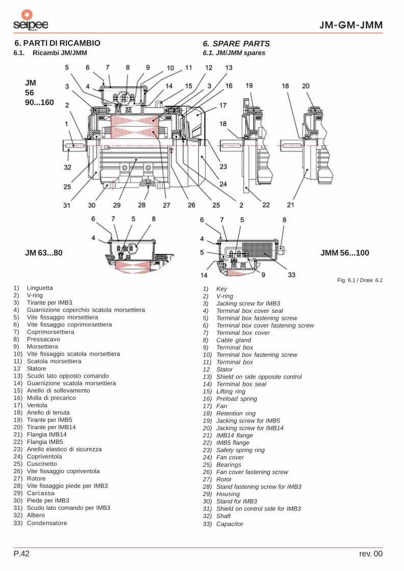
JM-GM-JMM
rev. 00P.42
6. SPARE PARTS6. PARTI DI RICAMBIO
Fig. 6.1 / Draw. 6.1
JM 63...80
JM5690...160
JMM 56...100
1) Key2) V-ring3) Jacking screw for IMB34) Terminal box cover seal5) Terminal box fastening screw6) Terminal box cover fastening screw7) Terminal box cover8) Cable gland9) Terminal box10) Terminal box fastening screw11) Terminal box12 Stator13) Shield on side opposite control14) Terminal box seal15) Lifting ring16) Preload spring17) Fan18) Retention ring19) Jacking screw for IMB520) Jacking screw for IMB1421) IMB14 flange22) IMB5 flange23) Safety spring ring24) Fan cover25) Bearings26) Fan cover fastening screw27) Rotor28) Stand fastening screw for IMB329) Housing30) Stand for IMB331) Shield on control side for IMB332) Shaft33) Capacitor
6.1. JM/JMM spares
1) Linguetta2) V-ring3) Tirante per IMB34) Guarnizione coperchio scatola morsettiera5) Vite fissaggio morsettiera6) Vite fissaggio coprimorsettiera7) Coprimorsettiera8) Pressacavo9) Morsettiera10) Vite fissaggio scatola morsettiera11) Scatola morsettiera12 Statore13) Scudo lato opposto comando14) Guarnizione scatola morsettiera15) Anello di sollevamento16) Molla di precarico17) Ventola18) Anello di tenuta19) Tirante per IMB520) Tirante per IMB1421) Flangia IMB1422) Flangia IMB523) Anello elastico di sicurezza24) Copriventola25) Cuscinetto26) Vite fissaggio copriventola27) Rotore28) Vite fissaggio piede per IMB329) Carcassa30) Piede per IMB331) Scudo lato comando per IMB332) Albero33) Condensatore
6.1. Ricambi JM/JMM
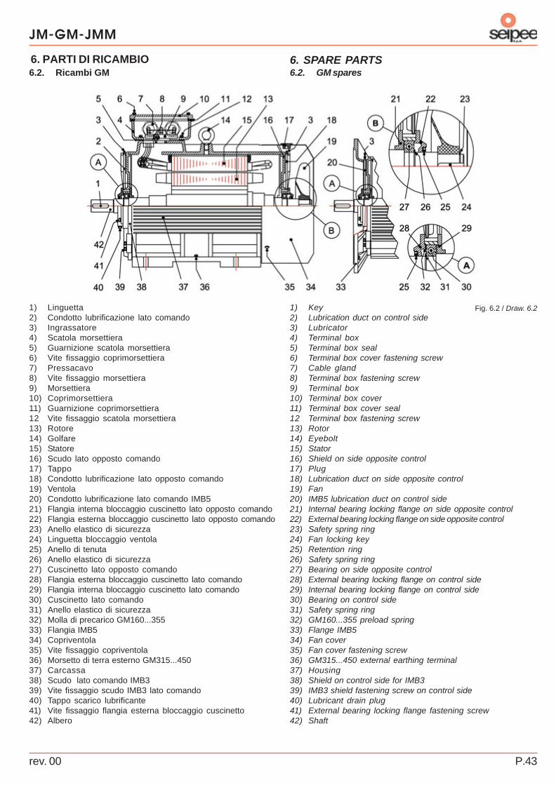
rev. 00 P.43
JM-GM-JMM
6. SPARE PARTS6. PARTI DI RICAMBIO
Fig. 6.2 / Draw. 6.21) Key2) Lubrication duct on control side3) Lubricator4) Terminal box5) Terminal box seal6) Terminal box cover fastening screw7) Cable gland8) Terminal box fastening screw9) Terminal box10) Terminal box cover11) Terminal box cover seal12 Terminal box fastening screw13) Rotor14) Eyebolt15) Stator16) Shield on side opposite control17) Plug18) Lubrication duct on side opposite control19) Fan20) IMB5 lubrication duct on control side21) Internal bearing locking flange on side opposite control22) External bearing locking flange on side opposite control23) Safety spring ring24) Fan locking key25) Retention ring26) Safety spring ring27) Bearing on side opposite control28) External bearing locking flange on control side29) Internal bearing locking flange on control side30) Bearing on control side31) Safety spring ring32) GM160...355 preload spring33) Flange IMB534) Fan cover35) Fan cover fastening screw36) GM315...450 external earthing terminal37) Housing38) Shield on control side for IMB339) IMB3 shield fastening screw on control side40) Lubricant drain plug41) External bearing locking flange fastening screw42) Shaft
6.2. GM spares
1) Linguetta2) Condotto lubrificazione lato comando3) Ingrassatore4) Scatola morsettiera5) Guarnizione scatola morsettiera6) Vite fissaggio coprimorsettiera7) Pressacavo8) Vite fissaggio morsettiera9) Morsettiera10) Coprimorsettiera11) Guarnizione coprimorsettiera12 Vite fissaggio scatola morsettiera13) Rotore14) Golfare15) Statore16) Scudo lato opposto comando17) Tappo18) Condotto lubrificazione lato opposto comando19) Ventola20) Condotto lubrificazione lato comando IMB521) Flangia interna bloccaggio cuscinetto lato opposto comando22) Flangia esterna bloccaggio cuscinetto lato opposto comando23) Anello elastico di sicurezza24) Linguetta bloccaggio ventola25) Anello di tenuta26) Anello elastico di sicurezza27) Cuscinetto lato opposto comando28) Flangia esterna bloccaggio cuscinetto lato comando29) Flangia interna bloccaggio cuscinetto lato comando30) Cuscinetto lato comando31) Anello elastico di sicurezza32) Molla di precarico GM160...35533) Flangia IMB534) Copriventola35) Vite fissaggio copriventola36) Morsetto di terra esterno GM315...45037) Carcassa38) Scudo lato comando IMB339) Vite fissaggio scudo IMB3 lato comando40) Tappo scarico lubrificante41) Vite fissaggio flangia esterna bloccaggio cuscinetto42) Albero
6.2. Ricambi GM