The Technology of Internet Protocol Networks -...
30
The Technology of Internet Protocol Networks CHAPTER 3 3 IPTV 03 11/2/06 8:54 AM Page 69
Transcript of The Technology of Internet Protocol Networks -...

The Technologyof Internet
ProtocolNetworks
CHAPTER 33
IPTV 03 11/2/06 8:54 AM Page 69

As the title of this book implies, IPTV’s foundation is the Internet Proto-col (IP) upon which the Internet is based. IP forms a common interna-tional language that allows a range of devices, from refrigerators tosupercomputers, to communicate anywhere in the world, over a range ofphysical media, including telephone wires, two-way radios, and opticalfiber. A layered approach to IP allows this universality by making differ-ent components of a digital network independent, and therefore inter-changeable. In its simplest form, IPTV services use IP to deliver digitalaudio and video bitstreams to consumer devices, ultimately to the tele-vision. However, IPTV is much more than a method of delivering digitalbitstreams. It also forms the basis for command and control messagesthat allow consumers to select content and interact in a bidirectionalmanner with the service delivery system. While broadcast television ispassive, IPTV has the ability to be interactive. This allows many newbusiness models to be developed with a television service. We will exam-ine some of these in later chapters.
We’ll begin this chapter with an overview of the basics of the IP suiteand how it delivers packets of data among devices. We will then divedeeper into some of the pertinent and more advanced protocols thatIPTV utilizes in creating a television service. Finally, we will look athow the MPEG-2 and MPEG-4 bitstreams are transported using Inter-net protocols.
The Internet Protocol SuiteThe IP suite is a set of communications protocols that forms the foun-dation for network communications. IP can be used to deliver dataacross a network from one digital device to another. While this peer-to-peer (P2P) model of communication is supported by IP, the more com-mon use is in a client-server architecture. In a typical client-servertransaction, the client computer requests data from a server computer.Web browsing is an example of the client-server model—for example,a company has a large commercial server hosting information aboutits products, and the client is a home computer requesting informationfrom this server. These computers rely on standardized softwarestacks or protocol stacks to communicate between one another. Theterm protocol stack refers to a suite of networking protocols and theactual software stack that executes those protocols on a specificmachine. And of course these protocol stacks are developed or com-
Chapter 370
IPTV 03 11/2/06 8:54 AM Page 70

piled specifically for each computer make. In this way, an Apple com-puter running Mac OS X can communicate with an IBM server run-ning Linux, or any other hundreds of combinations. The common IPlanguage among these computers abstracts away the differences inoperating systems, network connections, and hardware architectures(including central processing chips). As more and more consumer elec-tronics devices, in particular televisions, include IP stacks, they will beable to participate in the vast information flow of information on theInternet, in particular IPTV services.
The Layer Model
The power and versatility of the Internet protocols is that they weredeveloped in a modular, or layered, manner. Each layer is self-containedand communicates only with the layer above or below it. The communi-cation between the layers in the stack is standardized while the detailsof the operations inside the layers are not. In this way, the softwareinside a layer can be written in any way the programmer prefers as longas it uses the standard communication protocols between layers. Thepower to this approach is that if the details of a single layer change, itdoes not affect the other layers.
Figure 3-1 shows a typical software layered approach, or softwarestack. The highest layer is typically an application in which the user mayinteract with the software. This is usually called the user interface (UI).At the lowest layer is the software that interacts with the computer’shardware. Examples of this might include a video driver that manipu-lates graphics hardware registers or an Ethernet driver that receivesand transmits data. In between the upper and lower layers are addi-tional layers designed to interact with one another. This is why softwareis often referred to as a software stack, as these layers are stacked oneupon another to form a complete solution.
When two computers are communicating over a network, these sys-tems have similar protocol stacks and are able to send data up or downtheir respective stacks using a common language. Figure 3-2 showshow two computers can communicate through Internet protocolsbecause they both have the same common protocols and can pass dataup or down their software stacks despite their differences in hardwareand operating system. In this example, a home computer wants torequest a certain web page from a server out on the Internet. Thatrequest will originate at the application layer (a web browser) and is
71The Technology of Internet Protocol Networks
IPTV 03 11/2/06 8:54 AM Page 71

then sent down the home computer’s IP software stack (software lay-ers), which will prepare the data so the receiving server will under-stand the request. The data is sent from the home and makes its waythrough the Internet to the desired commercial server. The data willthen enter the server and is sent through its IP stack, where the infor-mation (request) is extracted from the data packet. When the serverdecides to send the requested web page, it will initiate a response sim-ilar to the transmission the home computer made. It will send thedesired web page data down its IP stack. This data will leave its com-puter and building, enter the Internet web, and ultimately make itsway to the home computer. The home computer will receive this data,break it down, and send it up its software stack till it reaches the webbrowser (application) and render it to the monitor.
That may seem like a lot of work just to get to a web page, but that’show the core IP technology works. The Internet itself may containdozens to hundreds of other devices that handle the data between thehome and the server. Each of those devices will have its own IP stack,and the data will pass up and down each. Despite all of these transac-tions between software layers, you can typically gain access to a webpage within a matter of seconds from making the request at thebrowser.
Chapter 372
Application Layer
Layer 3
Layer 2
Layer 1
Hardware
Figure 3-1Typicalsoftwarearchitecturelayeredapproach.
IPTV 03 11/2/06 8:54 AM Page 72

The OSI Reference Model
The definition of the various layers used in Internet communications arebased on the Open System Interconnection (OSI) standard or referencemodel. In fact, most, if not all, networks in operation today utilize theOSI reference model as their core architecture. OSI was developed by theInternational Organization for Standardization (ISO) back in the early1980s. ISO is a global standards body formed to create technical stan-dards and has representation from approximately 156 countries. TheOSI model is based on seven layers that define how computers talk andtransmit data. These seven layers are depicted in Figure 3-3.
• Layer 1: Physical. The physical layer defines a physical mediumover which the communications will take place. For example, thiswould represent the cable or wireless interface being used. Protocolsfor the physical layer would include the timing of signals and therelative voltages on the wire.
73The Technology of Internet Protocol Networks
Consumer’sHome
Business
Home PC Server
Layer 3
Layer 2
Layer 1
Layer 3
Layer 2
Layer 1
Internet/Network
Figure 3-2Passing data between two systems’ protocol stacks.
IPTV 03 11/2/06 8:54 AM Page 73

Chapter 374
Layer 7: Application
Layer 6: Presentation
Layer 5: Session
Layer 4: Transport
Layer 3: Network
Layer 2: Data Link
Layer 1: Physical
Figure 3-3OSI referencemodel.
IPTV 03 11/2/06 8:54 AM Page 74

• Layer 2: Data Link. The data link layer defines data formatting toenable it to move through the network. Therefore, a network datapacket could include parameters such as a checksum to verifyintegrity, source, and destination address, and the data itself. Thedata link layer has a Maximum Transmission Unit (MTU), or thelargest amount of data within a single data packet or datagramallowed within the network. Also, this layer handles the physicaland logical connections to the packet’s destination by using anetwork interface.
• Layer 3: Network. The network layer is responsible for routingdata throughout the entire system or from one network to another,enabling the data to be sent from the source to a destination. Assuch, the network layer is responsible for managing and directingdata packets. For example, on the server side, this layer breaks upextremely large blocks of data that exceed the MTU of the data linklayer into smaller transmittable blocks. The receiving computer’snetwork layer would be responsible for reassembling the fragmenteddata.
• Layer 4: Transport. The transport layer manages the transmissionmethod of the data within the network. For example, the desiredtransmission approach could mandate a reliable method of assuringdelivery, such as requesting a retransmission of lost or corrupt data.Other roles or functions that may be performed at the transportlayer include reordering of the data and error checking.
• Layer 5: Session. The session layer manages sessions between thetwo communicating computers within the network. For example, thesession layer would deal with initiating a session and negotiatingthe parameters to be used when communicating. Other roles orfunctions that may be performed at the session layer includemanaging the ongoing session, requesting a change in parameters,and terminating a session.
• Layer 6: Presentation. The presentation layer deals with how thedata elements will be transmitted. One way to think of this is themethod of converting data from the originating computer’s systemunique model to a more conventional or standard method for anyreceiving computer system. This might include the ordering of bitsand bytes within a number or converting floating point numbers.
• Layer 7: Application. The application layer is where data ismanaged and manipulated to perform network tasks or services.Examples of this could include web and e-mail access and file
75The Technology of Internet Protocol Networks
IPTV 03 11/2/06 8:54 AM Page 75
transfers. You can think of the application layer as the boundarybetween the user’s experience and the underlying computer andnetwork.
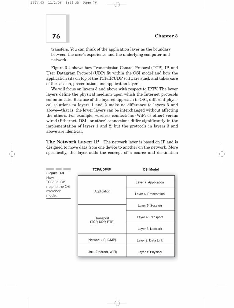
Figure 3-4 shows how Transmission Control Protocol (TCP), IP, andUser Datagram Protocol (UDP) fit within the OSI model and how theapplication sits on top of the TCP/IP/UDP software stack and takes careof the session, presentation, and application layers.
We will focus on layers 3 and above with respect to IPTV. The lowerlayers define the physical medium upon which the Internet protocolscommunicate. Because of the layered approach to OSI, different physi-cal solutions to layers 1 and 2 make no difference to layers 3 andabove—that is, the lower layers can be interchanged without affectingthe others. For example, wireless connections (WiFi or other) versuswired (Ethernet, DSL, or other) connections differ significantly in theimplementation of layers 1 and 2, but the protocols in layers 3 andabove are identical.
The Network Layer: IP The network layer is based on IP and isdesigned to move data from one device to another on the network. Morespecifically, the layer adds the concept of a source and destination
Chapter 376
Layer 7: Application
Layer 6: Presenation
Layer 5: Session
Layer 4: Transport
Layer 3: Network
Layer 2: Data Link
Layer 1: Physical
OSI ModelTCP/UDP/IP
Application
Transport(TCP, UDP, RTP)
Network (IP, IGMP)
Link (Ethernet, WiFi)
Figure 3-4HowTCP/IP/UDPmap to the OSIreferencemodel.
IPTV 03 11/2/06 8:54 AM Page 76

address into the framework. Under IP, each device on a network has aunique digital address (its IP address). To send a digital messagebetween any two computers on a network, the data is broken up intopackets (Figure 3-5) in a manner similar to the MPEG-2 standard. Atthe beginning of each packet in the IP header are two IP addresses: theaddress of the source (or sender) computer and the address of the desti-nation computer. This simple requirement enables the movement of datathrough the network, from the source, through intermediate routers, andfinally to its destination. Each device on the network looks at the desti-nation address in the IP header. If the address is for a different device,the receiving device passes the packet along to the next device until iteventually arrives at its destination. A good analogy for IP is sending aletter via a series of postcards: the letter is broken into small postcards,and each postcard has a source address and destination addressattached to it. The postcards are then sent individually until they allreach their final destination.
IP was designed to transport data to remote devices over an unreliablenetwork. If any one link in the web of connections on the network goesdown, packets may find an alternative route to their destination. This isaccomplished by duplicating packets; a device receiving a packet from asource destined for some other device may duplicate the packet and passit along to two other devices on the network. Conversely, if a device is toobusy at the moment, it might discard or drop packets that don’t belong toit. As a consequence, packets may be duplicated in some places, droppedin others, and may or may not eventually reach their destination.
The Transport Layer: TCP, UDP As its name implies, thetransport layer is the mechanism responsible for getting the data to itsdestination. As such, the transport layer’s tasks include reliability,
77The Technology of Internet Protocol Networks
Message MessagePacket
Figure 3-5IP messages are broken into smaller packets and distributed across the network.
IPTV 03 11/2/06 8:54 AM Page 77

sequencing, and ensuring the right application receives the designateddata. Again using the postcard analogy, under IP, the receiver may getduplicates of some postcards or never receive others. When re-creatingthe original letter, the receiver must put the postcards back in order,throw away duplicates, and request the missing ones. This is what thetransport layer protocols do. While this type of delivery system may beacceptable for e-mail, it is not ideal for more time-critical usages suchas television images.
The star of the transport layer would be Transmission Control Proto-col (TCP). TCP is a reliable, connection-oriented protocol that guaran-tees reception and in-order delivery of data from a sender to a receiver.For example, under TCP, if a packet doesn’t arrive in time and isassumed lost, a request will be sent to the sender to resend that packet.By handling this at the transport layer, all higher layers can safelyassume that all parts of the message were delivered. TCP also distin-guishes data for multiple applications (such as web server and e-mailserver) running on the same host, routing packets to the appropriateapplication. TCP can provide other services such as monitoring the net-work traffic and possibly throttling data transmission to avoid or mini-mize network congestion.
User Datagram Protocol (UDP), on the other hand, is a connectionlessprotocol that provides a best effort in getting the data to its final desti-nation. For many real-time applications (such as streaming A/V) that aretime critical or time sensitive, UDP is often used instead of TCP. UDPminimizes overhead and is not affected by network data loss or delays.But unlike TCP, UDP is not a guaranteed transport mechanism, and if apacket gets lost anywhere along the line, the destination application willsimply never get that data. Why would engineers design such as com-munication protocol? Broadcast IPTV services using IP multicast areactually a good example of how UDP might be preferred over TCP. A typ-ical MPEG-2 compressed bitstream might deliver millions of bits per sec-ond, contained in thousands of IP packets. The sending device isbroadcasting these thousands of packets potentially to hundreds ofdevices in the multicast group simultaneously. If a packet gets lost andis not received by one of the viewers, it would not make sense to halt thetransmission while a request is made to resend that missing packet. Inthis scenario, it’s easy to conceive that no progress could ever be madebecause of all of the thousands of possible retransmissions. Instead, theaffected receiver does the best it can to recover from the missing dataand continue with the transmission. Multicast really comes down to a“best effort” being made to broadcast data from a source to many desti-
Chapter 378
IPTV 03 11/2/06 8:54 AM Page 78

nations. Broadcast TV operates in a similar “best effort” fashion whenexposed to a weak or lost signal. Analog video exhibits artifacts such asnoise or ghosts, and digital satellite or cable displays digital artifactssuch as macroblocking (pixellation).
The Application Layer Typically applications that utilize TCP/IP/UDP take care of the application layer, presentation layer, and sessionlayer. The application layer is the software that interfaces directly to theTCP/IP/UDP stack. The application layer does not include these networkprotocol stacks, but simply utilizes them. This layer is the logic thatinvolves making use of the network and underlying protocols to accom-plish a user function such as e-mail or web browsing.
Figure 3-6 puts the various layers together by depicting a fictitiouscommunication session between a client and a server over the Internet.In the figure, two “hops” occur between the client’s machine and theserver. Assume the client is a consumer using a PC, browsing a commer-cial server’s catalog. She is shopping for a new pair of shoes and wants tosee a web page that consists of all of the shoes that are currently on sale.The PC’s web browser application initiates a request for a specific webpage. This request traverses down the PC’s network IP stack and out ontothe Internet. The request makes its way to the first hop, which is a router.The router, like all Internet-connected devices, has its own IP stack. How-ever, the packets in this case do not need to go past the network layerbecause this layer is where the network translation occurs. At this layer,the router device will know that this request is not destined for itself so itwill send the request onto the next hop. The router will accomplish this bysending the request down its stack and back into the network. The secondhop is similar to the first hop. The second router does not have to be anidentical router, or even run the same operating system. However, eachrouter has an IP stack following the same protocols.
Because literally millions of packets per second are traversingthrough these routers, there is a need for speed. These routers aredesigned to receive requests and send them on their way to the next hopas quickly as possible. Eventually, the request makes its way to the com-mercial shoe store’s web server. The request will make its way up theserver’s IP protocol stack. The web server will parse the request, formu-late a web page based on the details of the request, and send it down itsIP stack and back out onto the network. This response does not need tofollow the same path in which it came, but it can. Eventually the webpage arrives at the requesting PC, travels up the IP stack, and gets ren-dered by the browser application on the shopper’s monitor.
79The Technology of Internet Protocol Networks
IPTV 03 11/2/06 8:54 AM Page 79

Chapter 380
Internet/Network
Home PC
Router
Router
Server
Step 1
Step 1 Step 2
Step 2 Step 3
Step 3
Application
Transport (TCP,UDP, RTP)
Network (IP, IGMP)
Link (Ethernet, WiFi)
Application
Transport (TCP,UDP, RTP)
Network (IP, IGMP)
Link (Ethernet, WiFi)
Network (IP, IGMP)
Link (Ethernet, WiFi)
Network (IP, IGMP)
Link (Ethernet, WiFi)
Figure 3-6An example of a client-server session over the Internet.
IPTV 03 11/2/06 8:54 AM Page 80

Unicast versus MulticastIP carries some additional protocols designed to perform additional net-working functions. One such protocol is Internet Group ManagementProtocol (IGMP), which is used to manage multicast data. IP is primar-ily a unicast protocol; it was designed to convey messages from a singlesource device to a single destination device. However, IP also definesmulticast addresses, destination addresses that represent more than onedestination device. IGMP is used to define which devices are in whichmulticast group.
A unicast session is the conventional networking method two comput-ers use to communicate with one another within a private one-on-oneenvironment or session. The data exchanged between the two computersis intended for just these two machines and no others. Web browsing isa good example of an IP unicast session, with a client computer commu-nicating to a web server possibly requesting web pages, and the webserver sending the requested information or web pages back only to theoriginating web browsing machine. Unicast is the process of sendinginformation to one destination only. If a machine or computer is requiredto send the same data to multiple destinations but within unicast ses-sions, the originating computer must replicate the data and send indi-vidual streams to each of the desired recipient computers.
From an IPTV perspective, video on demand (VOD) is a great exam-ple of a unicast application. Take, for example, a typical IPTV networkthat includes a (unicast) VOD server, the broadband network, and theclient set-top box (STB) in a living room. The consumer would utilize theSTB’s user interface (UI) to exchange data with the VOD server. At thispoint, the consumer would initiate a unicast session with the VODserver. The client would ask for web pages depicting all available titlesalong with cost and receive them via the unicast session from the VODserver. At some point, the consumer finds a VOD title she wants to watchand then initiates the purchase process, which may include securityinterfaces, all via the client-server unicast session.
Once the VOD movie starts, the connection between the client andserver is still a unicast session because this VOD clip is not intended foreveryone, just the person who purchased it. Additionally it should bementioned that VOD clips are typically protected with some type of Dig-ital Rights Management (DRM) scheme to prevent anyone from stealinga clip or viewing it without paying for it, but we’ll get into DRM later.Let’s assume this consumer has paid for and is watching a VOD movie—
81The Technology of Internet Protocol Networks
IPTV 03 11/2/06 8:54 AM Page 81

a Doris Day classic—and it is streaming over the network to her homewithin a unicast session. Since this movie is VOD, the consumer can uti-lize the back channel to communicate with the VOD server and issuecommands. Don’t forget that all of this is still unicast with just the con-sumer and the VOD server communicating. Let’s say the phone ringsand the consumer wants to pause the movie. She can simply use theremote control to send a command back to the server telling it to pausethe movie. Because the network provides for unicast sessions, the serverunderstands that this particular household wants the movie to bepaused and does so by stopping the stream of data. Eventually, our DorisDay fan will hang up the phone and return to the movie. She could evenrewind the movie a little to get back into the flow of the movie. The com-munication that enables the client to control the VOD server is accom-plished with Internet protocols such as Real-Time Streaming Protocol(RTSP). We will discuss RTSP later in this chapter.
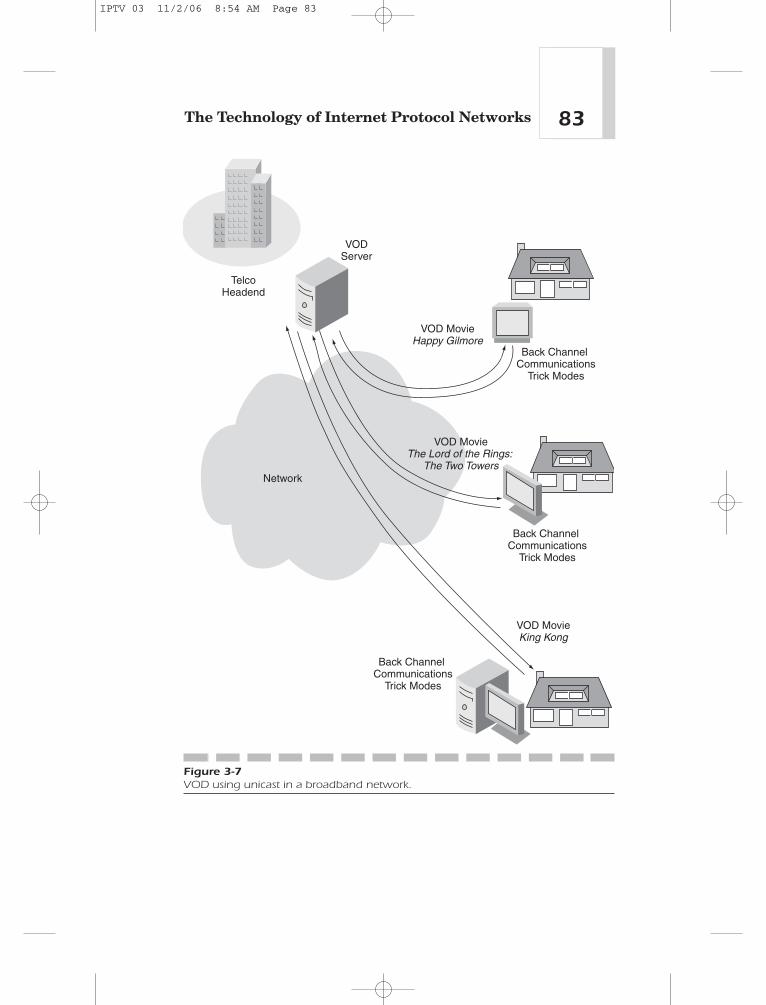
For each unicast VOD session, a separate stream of content exists onthe network. This enables VOD, but a significant amount of bandwidthon the overall network is allocated for each consumer’s VOD session. Forexample, if 1000 active movie sessions are underway, the network mustaccommodate 1000 separate streams. Each stream could be 5 Mbps(Megabits per second) for standard definition or upwards of 15 Mbps forhigh definition video. That could add up to a huge amount of bandwidthwithin the network.
Figure 3-7 shows a broadband network with three homes currentlyplaying a VOD movie. Each of these homes has an active unicast sessionwith a VOD server in the Telco headend. Three separate video bit-streams are flowing from the headend/VOD server to each house, alongwith a back channel for trick mode support (such as pause, play, fast-for-ward, and rewind).
Multicast, on the other hand, is the process of a single source sendingdata to multiple destinations (or broadcasting) at a single time. Broad-cast television transmits its signal to many users simultaneously with noreturn communication from the user back to the broadcasting server.Each broadcast television channel would have a unique IP multicastgroup. Using IGMP, clients are able to receive the broadcast packets andenable the routing of the broadcast stream to their network devicethrough the network. IGMP allows an individual host machine to “join”and “leave” multicast groups by responding to queries by a multicastcapable router.
The multicast technique enables a video operator to add broadcastvideo to a network. It saves a tremendous amount of network bandwidth
Chapter 382
IPTV 03 11/2/06 8:54 AM Page 82
83The Technology of Internet Protocol Networks
Back Channel Communications
Trick Modes
Back Channel Communications
Trick Modes
Back Channel Communications
Trick Modes
VOD MovieHappy Gilmore
VOD MovieThe Lord of the Rings:
The Two Towers
VOD MovieKing Kong
VODServer
TelcoHeadend
Network
Figure 3-7VOD using unicast in a broadband network.
IPTV 03 11/2/06 8:54 AM Page 83

Chapter 384
Broadcast VideoNBC 2006
Winter Olympics
Broadcast VideoNBC 2006
Winter Olympics
Broadcast VideoNBC 2006
Winter Olympics
VideoBroadcastEquipment
TelcoHeadend
Network
IGMP Router
Figure 3-8Broadcast video using multicast in a broadband network.
IPTV 03 11/2/06 8:54 AM Page 84

over unicast, but there is no reliability mechanism so lost packets staylost. Figure 3-8 shows a broadband network with three homes currentlyplaying the same broadcast video stream (the 2006 Winter Olympics).Each of these homes has an active multicast session receiving the samevideo bitstream that originates from the Telco headend.
Where does this leave us with regard to multicast versus unicast?Think of these as tools the IPTV network operator should have in a toolchest. Each has its unique purpose in building out a video service. Uni-cast is the tool of choice for VOD services. Multicast is the tool of choicefor broadcast services. Multicast has three advantages over unicast:
• Saves network bandwidth. By sending a common data streamout to many users at one time (versus several data streams to manyusers), multicast saves an enormous amount of network bandwidth.
• Lowers network congestion. Because multicast saves a lot ofnetwork bandwidth, it naturally saves a lot of network congestion,with fewer collisions and fewer lost or dropped packets at routers.
• Saves on servers or source load. With multicast, only one sourceis required to provide the stream instead of many sources.
For IGMP to be successful at obtaining the bandwidth savings of mul-ticasting instead of unicasting data, every router element in between thesource and destination devices must support IGMP. These routers trackevery request to join or leave the host group for a particular multicastaddress. Multicast can be applied in private networks where the networkoperator ensures that the routers within the network are all multicastenabled. Otherwise, the likelihood of users on the Internet being able toreceive multicast services is low because most routers out in the Internetare not multicast enabled. Movements to enable multicast networks,such as Mbone (Multicasting backbone), a virtual multicast networkwith multicast-enabled routers, are in the works.
Multimedia over IPMultimedia and networking is core to IPTV. Multimedia applications uti-lize various media types such as text, graphics, animations, audio, andvideo. Many network-based multimedia applications are availabletoday, and many bright and imaginative minds are working on ideas forapplications intended for high speed bidirectional networks. What new,
85The Technology of Internet Protocol Networks
IPTV 03 11/2/06 8:54 AM Page 85

innovative multimedia applications will come out of IPTV are yet to beseen. Some examples of multimedia applications include the following:
• Video conferencing. Video conferencing would make aninteresting product differentiator for an IPTV service. It includesthe real-time streaming of audio (voice) and video data over thebroadband service and could be included within the IPTV STB.
• Streaming audio. Streaming audio is an existing multimediaapplication built into existing IPTV devices, which can becustomized by the IPTV network operator with an attractivecommercial audio package. Examples include Internet radio andaudio webcast discussions.
• Streaming audio and video. Much like streaming audio,streaming audio and video is an existing multimedia applicationsupported by IPTV devices. The IPTV network operator can bundlein attractive streaming AV services to help differentiate itself fromcompetitors. Examples include education or in-class discussions,video webcasts, and on-demand archive programming.
• Rich graphics and animations. Graphics and animations providea rich multimedia environment to aid in the adoption of advanced ornew services (at the IPTV STB), such as interactive services.
• Internet telephony. Internet telephony is a growing multimediaapplication that requires streaming audio over a broadbandnetwork. This application enables IPTV network operators to offer atriple-play service (voice, data, and video) to their customers.
These applications are being applied to various products and ser-vices, ranging from distance learning, to business to business (B2B)services and business to consumer (B2C) services, to digital signageand collaboration.
Because networked multimedia applications are so important, it iscritical for the IPTV network architect or content creator to understandthe issues associated with multimedia networking as well as what toolsare available to enable effective and compelling new applications. Fol-lowing are three top issues for multimedia applications:
• Network bandwidth. Multimedia applications consume a largeamount of network bandwidth. For example, a high quality MPEG-2 movie or broadcast stream could consume 4 to 5 Mbps. Advancedcompression (MPEG-4/H.264/AVC/JVT or VC-1/WM9) would greatlyimprove these numbers and reduce the required bandwidth to
Chapter 386
IPTV 03 11/2/06 8:54 AM Page 86

approximately 1 to 2 Mbps. However, this is still a large amount ofnetwork bandwidth required for a single channel of content.Multiply this by a couple hundred channels and the service isconsuming a huge amount of network bandwidth. Careful attentionmust be made when architecting the commercial IPTV servicepackages and network to ensure sufficient network bandwidth willbe available to ensure scalability.
• Real-time data flow. Multimedia applications require real-timeresponse. To stream a two-hour movie at the bit rates identifiedpreviously requires constant and consistent real-time processing.The receiver has multiple data buffers, including the input bufferand the decode buffer. It will be processing data in real time fromthese buffers, and the appropriate buffer levels must be maintained(as data gets consumed, new data must enter the buffer); otherwise,a buffer underflow condition could occur, resulting in broken audio/video. Breaks and interruptions in the content presentation are anunacceptable consumer experience. This puts a lot of pressure onreliable network delivery to process multimedia content in real time.
• Bursts of network traffic. Audio and video (multimedia data)content has a tendency to be delivered to the IPTV STB in burstsdue to how the content gets digitally encoded or how the data getsrouted through the IPTV network. This traffic pattern can playhavoc with real-time processing. Some mechanism within thesystem must smooth out the data delivery to the receiver. Otherwise,if data comes in too fast, the input buffers will overflow, resulting inlost data for decoding. If data comes in too slow, this would result indata underflow, and the application will be starved of data. In eithercase, the resulting consumer experience will be unacceptable.
Video Streaming Protocols
The task of streaming and decoding digital audio and video over IP net-works (suitable for viewing in the living room) provides a new set ofchallenges from traditional satellite and cable networks. For example,IP networks traditionally provide no real-time quality of service (QoS).Dropping packets, introducing delay or network jitter, has been typi-cally acceptable as long as the data gets to its final destination. How-ever, real-time digital video playback over IP networks cannot affordthese disruptions. Additionally, a significant amount of network band-
87The Technology of Internet Protocol Networks
IPTV 03 11/2/06 8:54 AM Page 87

width is required for video playback, which stresses the network evenfurther and can also introduce errors or dropped packets. To combat thevarious problems associated with IP networks (for real-time streamingof multimedia content), various Internet protocols have been developedand proven out. These protocols address QoS, time (clock) management,session management, VOD trick mode support, and so on. This sectionprovides a brief overview of some of these protocols.
The Protocol Stack for Streaming Media The software for astreaming media device would incorporate all of the protocols shown inFigure 3-9, which reside on top of the IP network layer and UDP trans-port layer. The relationships among the various protocols as discussedin this section are also shown in this figure.
The following additional protocols on top of the TCP transport layermay also be included to complete the software stack:
• FTP. In contrast to live broadcast or streaming of media content,non–real-time cached video services can be supported by the FileTransport Protocol (FTP). Timing specific protocol layers such asRTP are not needed when using FTP.
• TFTP/MTFTP. Multicast Trivial File Transfer Protocol is a simpleprotocol used to transfer files and is implemented on top of UDP.This protocol is designed to have a small memory footprint and iseasy to implement. Therefore, it lacks most of the features of regularFTP. This protocol is useful in booting machines that lack non-volatile memory or software downloads.
Chapter 388
FTP HTTP
SI
TCP TCPUDP
IP
Physical, Data, and Link Layers
System Layer
RTP
MediaStreams
RTCP RTSPIGMP
Figure 3-9Variousstreamingmediaprotocols.
IPTV 03 11/2/06 8:54 AM Page 88
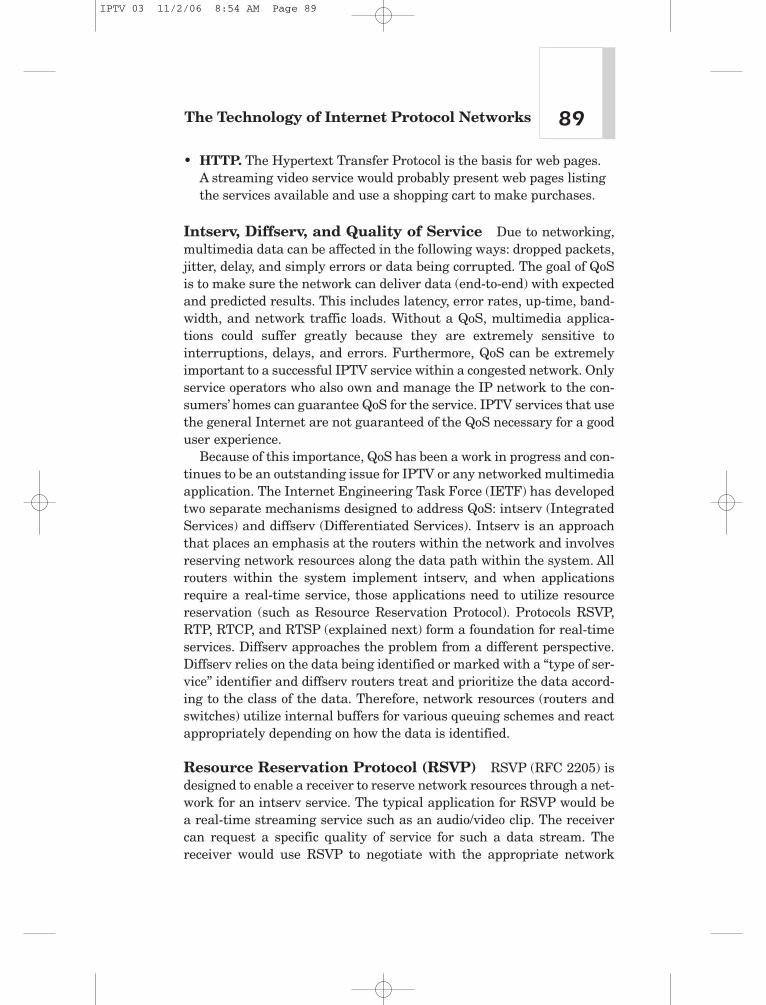
• HTTP. The Hypertext Transfer Protocol is the basis for web pages. A streaming video service would probably present web pages listingthe services available and use a shopping cart to make purchases.
Intserv, Diffserv, and Quality of Service Due to networking,multimedia data can be affected in the following ways: dropped packets,jitter, delay, and simply errors or data being corrupted. The goal of QoSis to make sure the network can deliver data (end-to-end) with expectedand predicted results. This includes latency, error rates, up-time, band-width, and network traffic loads. Without a QoS, multimedia applica-tions could suffer greatly because they are extremely sensitive tointerruptions, delays, and errors. Furthermore, QoS can be extremelyimportant to a successful IPTV service within a congested network. Onlyservice operators who also own and manage the IP network to the con-sumers’ homes can guarantee QoS for the service. IPTV services that usethe general Internet are not guaranteed of the QoS necessary for a gooduser experience.
Because of this importance, QoS has been a work in progress and con-tinues to be an outstanding issue for IPTV or any networked multimediaapplication. The Internet Engineering Task Force (IETF) has developedtwo separate mechanisms designed to address QoS: intserv (IntegratedServices) and diffserv (Differentiated Services). Intserv is an approachthat places an emphasis at the routers within the network and involvesreserving network resources along the data path within the system. Allrouters within the system implement intserv, and when applicationsrequire a real-time service, those applications need to utilize resourcereservation (such as Resource Reservation Protocol). Protocols RSVP,RTP, RTCP, and RTSP (explained next) form a foundation for real-timeservices. Diffserv approaches the problem from a different perspective.Diffserv relies on the data being identified or marked with a “type of ser-vice” identifier and diffserv routers treat and prioritize the data accord-ing to the class of the data. Therefore, network resources (routers andswitches) utilize internal buffers for various queuing schemes and reactappropriately depending on how the data is identified.
Resource Reservation Protocol (RSVP) RSVP (RFC 2205) isdesigned to enable a receiver to reserve network resources through a net-work for an intserv service. The typical application for RSVP would bea real-time streaming service such as an audio/video clip. The receivercan request a specific quality of service for such a data stream. Thereceiver would use RSVP to negotiate with the appropriate network
89The Technology of Internet Protocol Networks
IPTV 03 11/2/06 8:54 AM Page 89

resources (such as routers) along with the desired parameters. Oncereservations are set up, RSVP is responsible for maintaining routerstates and ultimately relinquishing the reservations. Following are theprimary features of RSVP:
• RSVP flows are simplex, where RSVP reserve resources to senddata in only one direction, from the sender to the receiver.
• RSVP supports both unicast and multicast network traffic andmanages soft reservation states and adapts to changing membershipand routes.
• RSVP is receiver oriented—the receiver initiates and maintains thedata flow and the associated resource reservations with each nodewithin the network that will carry the stream or data.
• RSVP provides opaque transport of traffic control and policy controlparameters to adapt to new technologies.
Real-time Transport Protocol (RTP) IP networks can be inher-ently unreliable and experience unpredictable jitter and delay. The mul-timedia data that travels on the IP networks must arrive on time and inthe same order in which it was sent. RTP (RFC 3550) was designed toaddress the time-critical requirement of multimedia bitstreams and pro-vides support of the transport of real-time data from the source to thereceiver. In doing so, it provides a timestamp and sequence number toassist in dealing with these timing issues. Figure 3-10 shows an RTPpacket encapsulated in UDP and IP. The RTP packet has a 12 byteheader followed by the data payload containing the multimedia datasuch as a compressed bitstream. This diagram shows seven 188 bytetransport packets that constitute the RTP payload. Within the RTPheader is important information such as the timestamp associated withthe data in the payload.
The timestamp is the most important piece of data for the real-timeapplication. The source adds a timestamp when the data is first sampledand subsequent timestamps increase over time. The receiver can use thetimestamp as a mechanism to determine when the data needs to beprocessed. Timestamps also provide a mechanism to aid in synchroniza-tion between services, such as audio and video. It should be noted thatthis synchronization is not intended for lip-sync and similar applications.Additional timestamps within the compressed bitstreams are intendedfor application layer synchronization (for example, PTS, or presentationtimestamp for lip-sync).
Chapter 390
IPTV 03 11/2/06 8:54 AM Page 90
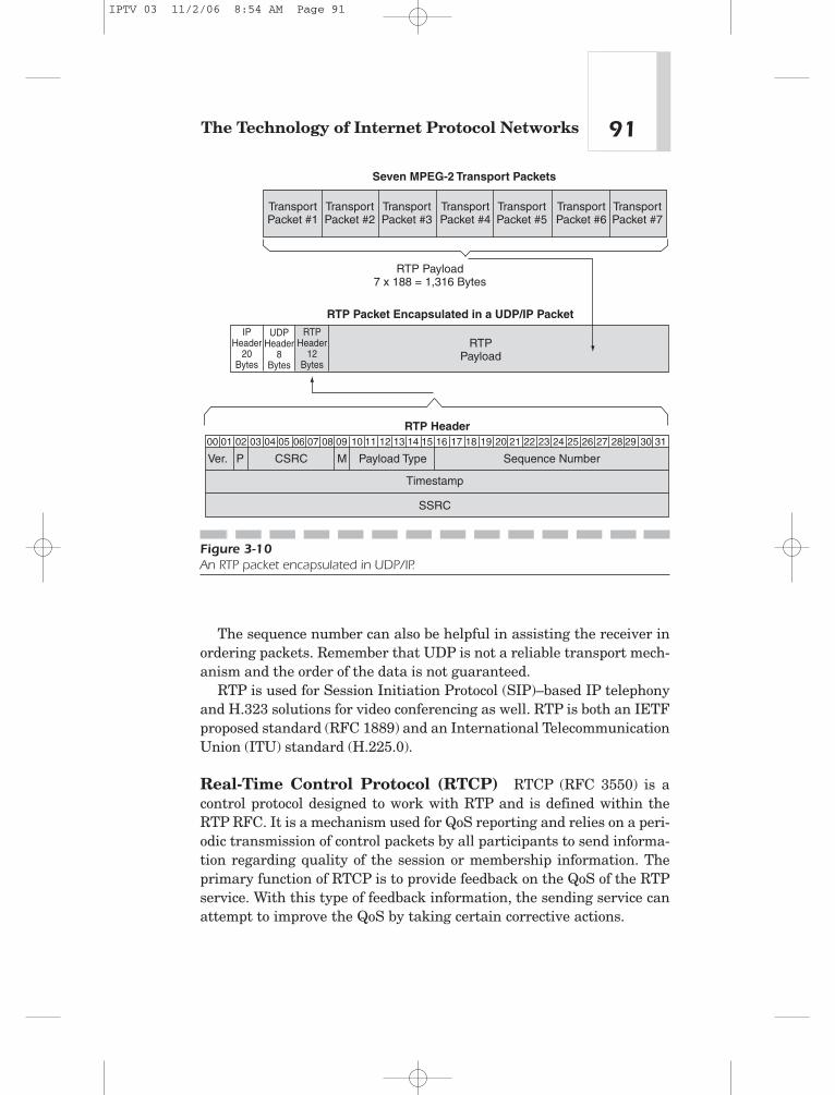
The sequence number can also be helpful in assisting the receiver inordering packets. Remember that UDP is not a reliable transport mech-anism and the order of the data is not guaranteed.
RTP is used for Session Initiation Protocol (SIP)–based IP telephonyand H.323 solutions for video conferencing as well. RTP is both an IETFproposed standard (RFC 1889) and an International TelecommunicationUnion (ITU) standard (H.225.0).
Real-Time Control Protocol (RTCP) RTCP (RFC 3550) is acontrol protocol designed to work with RTP and is defined within theRTP RFC. It is a mechanism used for QoS reporting and relies on a peri-odic transmission of control packets by all participants to send informa-tion regarding quality of the session or membership information. Theprimary function of RTCP is to provide feedback on the QoS of the RTPservice. With this type of feedback information, the sending service canattempt to improve the QoS by taking certain corrective actions.
91The Technology of Internet Protocol Networks
Seven MPEG-2 Transport Packets
RTP Packet Encapsulated in a UDP/IP Packet
RTP Header
TransportPacket #1
TransportPacket #2
TransportPacket #3
TransportPacket #4
TransportPacket #5
TransportPacket #6
TransportPacket #7
RTPPayload
IPHeader
20Bytes
RTPHeader
12Bytes
UDPHeader
8Bytes
RTP Payload7 x 188 = 1,316 Bytes
Ver. P M Payload Type Sequence NumberCSRC
Timestamp
SSRC
00 01 02 03 04 05 06 07 08 09 10 11 12 13 14 15 16 17 18 19 20 21 22 23 24 25 26 27 28 29 30 31
Figure 3-10An RTP packet encapsulated in UDP/IP.
IPTV 03 11/2/06 8:54 AM Page 91

Real-Time Streaming Protocol (RTSP) RTSP (RFC 2326) is anapplication-level protocol designed to work with lower-lever multimediastreaming protocols such as RTP. Its primary role is to provide controlover streaming media much like a VCR, allowing functions such aspause or play. It is a great tool for VOD applications that have a unicastsession between the client and the VOD server. The client can issue anRTSP PLAY command to start the movie, issue a PAUSE command tostop the movie temporarily, and so on. RTSP also provides the ability tochoose delivery channels such as UDP, multicast UDP, and TCP. RTSPsupports the following methods:
• Options. Enable the client and the server to communicate to theother party their supported options.
• Describe. The mechanism used by the server to communicate to theclient the media object’s (such as VOD movie) description.
• Announce. Serves two purposes:
– The client can post the description of a media object (identified bythe request URL) to the server.
– The server can update the session description in real time.
• Setup. Enables the client to request the transport mechanism to beused for an identified media stream. Additionally, the client can changethe transport parameters of an existing stream with this method.
• Play. Enables the client to tell the server to start sending thebitstream via the transport mechanism specified in a setup request.The client cannot issue a play request until the server has responded(previously) with a successful response from a setup request.
• Pause. Causes the media stream to be stopped temporarily. Theserver resources are typically not lost. However, the server may closea session and free resources if a timeout parameter (defined in thesession header) is exceeded.
• Teardown. Stops the media stream delivery and frees all associatednetwork resources associated with the session.
• Get_Parameter. This request retrieves the value of a parameter ofa specified stream.
• Set_Parameter. This method enables the client to issue a requestto set the value of a parameter of a specified stream.
• Redirect. Enables a server to inform a client that it must connect toanother server. The redirect request contains the mandatory headerlocation in which the client should issue requests for connection.
Chapter 392
IPTV 03 11/2/06 8:54 AM Page 92

• Record. Initiates recording a range of media data according to thepresentation description.
Session Description Protocol (SDP) RFC 2327 defines the SDP,which is intended for describing multimedia sessions that include sessionannouncement, session invitation, and other forms of session initiation.A common usage of SDP is for a client to announce a conference sessionby periodically multicasting an announcement packet to a well-knownmulticast address and port via the session announcement protocol.
Session Announcement Protocol (SAP) RFC 2974 defines theSAP, a protocol used to communicate information regarding multicastsessions. An SAP announcer periodically sends a multicast announce-ment packet out to a well-known multicast address and port. These mul-ticast announcements are of the same scope as the session it isannouncing. This way, it is ensuring that those clients can join the mul-ticast, and clients can listen to these announcements to determinewhether they want to request the content.
Encapsulating Media Data into IP Packets
The satellite and cable industries were the early adopters of sending dig-ital media into residential homes, and the tools available at the time wereMPEG-2 digital bitstreams (MPEG-2 codec) along with MPEG-2 trans-port stream (TS). RTP, along with advanced compression, is the emergingtechnology for IPTV or IP networks. The natural progression of IPTV hasbeen to leverage the more mature technology: MPEG-2 codec plus MPEG-2 TS encapsulated with IP, with a transition to advanced compressioncodec plus RTP encapsulated within IP. This section explores the two dif-ferent approaches with a focus on required overhead for each.
Encapsulation of MPEG-2 Transport in IP MPEG-2 trans-port streams consist of a series of 188 byte transport packets. The sim-plest way to transport these packets over IP is to insert seven of theminto the payload of an IP packet. Ethernet’s maximum MTU size is 1500bytes; therefore, seven MPEG-2 transport packets will fit within the Eth-ernet frame and eight would exceed it. Figure 3-11 shows how MPEG-2TS packets can be encapsulated within an UDP/IP packet.
93The Technology of Internet Protocol Networks
IPTV 03 11/2/06 8:54 AM Page 93

Sending MPEG-2 TS packets over UDP is the simplest method, butthis requires sufficient QoS on the network to be effective. It is usedextensively within the private networks of cable and telephone compa-nies to deliver MPEG-2 transport streams throughout the system. Forgeneral delivery over the unmanaged Internet without QoS guarantees,streaming protocols such as RTP need to be used.
Encapsulation of RTP in IP Two approaches are used for trans-porting media data with RTP. The first approach would be identical toplacing multiple MPEG-2 TS packets into an IP packet, with the excep-tion of the MPEG-2 TS packets first being encapsulated in an RTPpacket. Figure 3-10 showed how seven MPEG-2 TS packets were encap-sulated within the RTP payload plus the RTP header and UDP/IP head-ers. The Digital Video Broadcasting over IP Infrastructure (DVB-IPI)group uses this approach.
The other approach is to transport Advanced Video Coding (AVC) dataover RTP. RFC 3984 defines the RTP payload format for H.264 (AVC)video. The AVC specification defines a Video Coding Layer (VCL) and aNetwork Abstraction Layer (NAL). The VCL contains the signal pro-cessing functionality of the codec. The output of the VCL is slices thatcontain an integer number of macroblocks of video data. The NALencoder encapsulates the slice output of the VCL encoder into NALunits. NAL units are suitable for transmission over networks via RTPand are the smallest possible entity that can be decoded without knowl-edge of other NAL units. An NAL unit consists of a 1 byte header andpayload, and these NAL units are carefully mapped into RTP payloads.
Channel Change Delay
A key requirement in a commercial IPTV service is fast channel change,sometimes referred to as channel zapping. Channel zapping occurs when
Chapter 394
7 MPEG-2 TS Packets (1,316 Bytes)
IPHeader
20Bytes
UDPHeader
8Bytes
Figure 3-11MPEG-2 TS encapsulated in UDP/IP.
IPTV 03 11/2/06 8:54 AM Page 94

someone starts cycling rapidly through the channels with the remotecontrol and an IP STB. Most consumers expect to see video within a sec-ond. If the device changes channel too slowly, consumers can get annoyedand may opt to discontinue the service.
Because IPTV relies on a complex digital switched network and acomplex IP software stack, many bottlenecks can occur within the IPend-to-end system, which could adversely affect the time it takes tochange channels. Figure 3-12 shows a simplified network diagram of atypical IPTV system. It shows all of the main components in whichaudio/video data needs to flow through to make its way to the consumer’shome. Additionally, when a channel change is selected, the client needsto signal over the bidirectional network back to the network/system torequest the necessary routing for the A/V data.
Figure 3-13 represents a typical timeline for an IPTV channel changewithin a multicast commercial offering. For this example, ignore thetime required within the client software to render a UI screen (such as agrid guide) from which someone can change channels. Also, assume thechannel lineup is cached within the client machine. The client is bootedup and streaming a channel of video to the television.
95The Technology of Internet Protocol Networks
SuperHeadend
GigE
GigE
Video HubOffices
Video CentralOffices
Consumer Households
Video NetworkAccess Interfaces
Figure 3-12Network diagram of an IPTV system.
IPTV 03 11/2/06 8:54 AM Page 95

Following is a description of the process shown in Figure 3-13:
• t0. t0 is the moment in time that the consumer selects theappropriate button on the remote control in which a channel changeis initiated.
• t1. The client has to tell the network and server to stop sending thecurrent A/V stream. If this step never takes place and the client asksfor another A/V stream, the network will stream a second stream tothe home. In fact, without IGMP leave requests, the system wouldcontinuously ask for more and more streams. The equipment in thehome, starting with the router and gateway, will get swamped withtoo much data and eventually start to drop packets, which will affectvideo quality. Therefore, t1 is all about the client telling the networkto stop streaming data, and this step typically takes approximately150 milliseconds (ms). Note that some routers are enabled to handleinstantaneous leave commands, which could dramatically reduce thetime for t1. However, not all networks employ routers with thisfeature. For this example, we are factoring in the time required for arouter that does not support instantaneous leave commands.
• t2. Once the client has stopped the multicast stream (with an IGMPleave request), the client will join a different multicast session. Thisis accomplished with an IGMP join request. The time required for
Chapter 396
t0 t1 t2 t3 t4 t5 t6 t7 t8
0 250ms 500ms 750ms 1000ms
t0 = Channel change selected
t1 = Set-top issues IGMP (multicast) leave g duration ~150ms
t2 = Set-top issues IGMP (multicast) join g duration ~15ms
t3 = Data path routed (e.g., GW, DSLAM, distribution network) g duration ~50ms
t4 = Process system information (e.g., PAT/PMT parsing) g duration g ~100ms
t5 = Decryption keys (if required) g duration ~100ms
t6 = Dejitter buffer fills and reaches threshold g duration ~300ms
t7 = Time to start decoding (e.g., first sequence header) g duration ~250ms
t8 = Decoding of data and display first frame g duration ~35ms
Figure 3-13IPTV channel change timeline.
IPTV 03 11/2/06 8:54 AM Page 96

this can be relatively small. Note that, in general, the fewer hops theIGMP requests need to travel the quicker the turnaround time willbe for the network to stop the flow or route new data. This is alsotrue for t1.
• t3. This is the time required for the system to flow the content to thehome; 50 ms is a reasonable time required for this task. The systemusually is able to route multicast video streams efficiently through thenetwork to the consumer’s home, so the typical time required for thisis (usually) relatively small. With a Telco system, if the Video NetworkAccess equipment or DSLAM (Digital Subscriber Line AccessMultiplexer) already has the multicast data available, it can simplyroute that data with the new request. Otherwise, the DSLAM willneed to request this data traffic from an upstream router.
• t4. The client is now receiving data at the Ethernet jack. The clientmust start to parse the incoming data for relevant system data (suchas channel information, digital format descriptions, and so on). Thisdata will be used later for the demux/decode steps.
• t5. If the system has implemented Conditional Access (CA) or DRM,the client will need to get the proper decryption keys from either anin-band or an out-of-band mechanism. Once the decryption system isconfigured with valid keys, when data comes to the client it will getdecrypted and stored in a buffer for demux/decoding. This step isrequired only if the incoming content is protected and has differentkeys than the previous channel.
• t6. A step that will consume a relatively large amount of time is thefilling of a dejitter buffer with A/V data. Because the data is flowingover an IP network, the data comes to the client in bursts. To combatthis, the client usually implements a large dejitter buffer. The size ofthis buffer is driven by the overall system requirements that arederived from the system architecture. For this example, we haveselected a 300 ms dejitter buffer.
• t7. Many factors are involved in the time required to start decoding,and an important one is the time before an MPEG Intra frame (I-frame) arrives. I-frames are the only frames that contain enoughinformation for the decoder to build a complete picture suitable forrendering. Depending on the digital encoder’s settings, the I-framespacing can vary. Sequence headers contain the necessaryinformation describing parameters within a sequence of pictures.The decoder must search for a sequence header and the first I-framebefore it can decode and render any meaningful pictures to the
97The Technology of Internet Protocol Networks
IPTV 03 11/2/06 8:54 AM Page 97

television. For this example, we assume that these sequence headersarrive every 500 ms. Depending on when the client starts to bufferincoming data, the time it has to wait for a new I-frame can beanywhere from 0 to 500 ms. On average the client will have to wait250 ms for the sequence header of an I-frame to arrive. You canprobably see that this time will vary from channel change to channelchange, and that this time will be a relatively large amount of time.Also, these I-frames can easily contain five times the amount of bitsthan the other frames in the video sequence. So the networkarchitect wants to minimize the number of large I-frames within the system to maximize network bandwidth. But the spacing ofthese I-frames directly relates to the time required for channelchange.
• t8. The time for the client to decode an I-frame is extremely small.The bulk of t8’s time is spent aligning the picture with the verticalblanking and the proper field (odd versus even field).
Using this system, it’s going to take approximately 1 second for everychannel change. Of course, the time will vary slightly from channelchange to channel change. But an average of 1 second would be a rea-sonable expectation placed on an IP STB. Also, a 1 second channelchange is a pretty good response and would provide a relatively good con-sumer experience. However, many areas can easily push this timeupward toward 2 seconds. Network architects need to pay careful atten-tion to all of these parameters because they could lead to a pleasant orunpleasant consumer experience with respect to channel change.
Chapter 398
IPTV 03 11/2/06 8:54 AM Page 98