THE TARA HANDPUMP - IRC · The TARA handpump has been developed by staff of the Mirpur ... B5 -2 B5...
178
232.2 87 TA THE TARA HANDPUMP PRODUCTION MANUAL AND DRAWINGS INTERNATIONAL VERSION ];.;.;,• DPHE m unicef RURAL WATER SUPPLY & SANITATION PROGRAMME DHAKA-BANGLADESH
Transcript of THE TARA HANDPUMP - IRC · The TARA handpump has been developed by staff of the Mirpur ... B5 -2 B5...

232.287 TA
THE TARA HANDPUMPPRODUCTION MANUAL AND DRAWINGS
INTERNATIONAL VERSION
] ; . ; . ; ,•
DPHEmunicef
RURAL WATER SUPPLY & SANITATION PROGRAMME
DHAKA-BANGLADESH
THE TARA HANDPTJMPPRODUCTION MANUAL AND DRAWINGS
DHAKA-BANGLADESH
INTERNATIONAL VERSION

TARA HANDPUMP PRODUCTION MANUAL PAGE 1
THE TARA HANDPUMP
The TARA handpump is a low-lift direct action handpump suitable for pumping heads up to 15 metres. It is manufactured from plasticsand mild steel and can easily be produced in most developing countries. The pump has been extensively field tested and is now beinginstalled on a regular basis under the Government of Bangladesh Rural Water Supply and Sanitation Programme assisted by UNICEF,with funds from DANIDA,SDC and UNCDF. In the period July 1986-June 1987, some 1,750 TARAs were installed, bringing the totalnumber of TARAs in operation in Bangladesh to 3,000.
The TARA handpump has been developed by staff of the Mirpur Agricultural Workshop Training School, Dhaka (MAWTS), the WorldBank/UNDP Handpump Testing Project INT/81/026 and UNICEF Dhaka. Staff of the international Centre for Diarrhoeal Disease Research,Bangladesh (ICDDR.B) have also been involved in the field testing of the pump.
Note:This production manual was originally produced specifically for the procurement by UNICEF, Dhaka of targe numbers of TARAhandpumps for the Government of Bangladesh. One essential purpose of the original manual was to encourage and help interestedmanufacturers to undertake production of the pump in Bangladesh. This "international" version of the manual is being made availableto enable governments, development organizations and manufacturers in other developing countries either to set up production of theTARA, or to develop their own version of the pump suitable for local needs.

CHECKLIST
COVER
1 /
2 /
3
I
A
A1A1A1A1A1A1Al
A2A2A2A2A2A2
1
' 1
- 0-1-2-3-4-5
-0
-0-1 /- 2 /-3-4 /-5 /-6
-0- 1 /- 2 /- 3 /- 4 /- 5 /
' 11
11
11111
OF
A3A3A3A3A3A3
A4A4A4A4A4A4A4A4
A5A C
At)A5A5
PAGES
-0-1- 2 / 1-3 / 1: 4 / 1- 5 / 1
-0-1 / 1-2 / 1-3 / 1-4-5-6-7 / 1
- 0i
- i
-2-3
B -0
B1 -0B1 -1
1.00 /
B1 -2B1 -3B1 -4
1.10 /1.11 /1.12 /1.13 /4 4 A 1
1.14 /
B1 -5B1 -6B1 -7
1.201.211.221.23
1
/ 1
111r1
TARA HANOPUMP
B1 -8B1 -9
1.30 / 11.311.32
B1 -10B1 -11
1.40*l A 4
1.411.42
B2 -0B2 -1 / 1
B2 -2B2 - 3 / 1
2.00 / 12.11 / 12.12 / 1
£.. i *y
2.14
PRODUCTION
B3 -0B3 -1 / 1
3.00 / 1
B3 - 2 / 1B3 - 3B3 - 4 / 1
3.10 / 13.113.12 / 13.13
3.15
3.17B3 -6B3 - 7 / 1
3.22 / 1
MANUAL
B4 -0B4 -1
4.00 /
B4 -2B4 - 3B4 -4
4.104.11 /4.124.13
B4 -5B4 -6B4 -7
B4 -9
4.20 /4.214.224.234.24
4.26 /
/ 1
1
1
/ 1
1
1
PAGE 2 / 1
This checklist is validto include Amendment No. 01
B4 -10B4 -11B4 - 1 2 / 1
4.304.314.324.33 / 1
B5 -0B5 -1
5.00
B5 -2B5 -3B4 ,4 / 1
5.11 / 15.125.135.14 1 1
B5 - 5B5 -6B5 -7
5.205.215.225.235.24
B6 - 0B6 -1 / 1B6 -2B6 -3
6.00 / 16.116.126.13
B7 -0B7 -1B7 -2B7 -3B7 -4 / 1
7.107.13 / 1
7.15 7 1
B7 -6B7 -7B7 -8B7 -9
7.207.227.24
B8 -0B8 -1B8 -2
8.00
R -0
R1 -1R1 -2R1 -3R1 -4R1 -5
R2 -1R2 -2R2 -3
END COVER

CONTENTS
THE TARA HANDPUMP
CHECKLIST OF PAGES
INTRODUCTION
TARA HANDPUMP PRODUCTION MANUAL
. • • . • •
SECTION A- SYSTEM DRAWINGS AND GENERAL PROCESS INFORMATION
SECTION B - PRODUCTION
A1 SYSTEM DRAWINGS
A2 LIST OF ASSEMBLIES SUB-ASSEMBLIES AND PARTS
A3 SELECTED COMMON PROCESSES
A4 MATERIALS AND THEIR TESTING METHODS
A5 INSPECTION AND TESTING
INFORMATION AND DRAWINGS
B1 PUMP HEAD ASSEMBLY
B2 HANDLE ASSEMBLY
B3 PUMP ROD ASSEMBLY WITH TOP CONNECTOR
B4 PISTON ASSEMBLY WITH BOTTOM CONNECTOR
B5 FOOT VALVE ASSEMBLY
B6 CYLINDER ASSEMBLY
B7 TUBEWELL ASSEMBLY v
B8 RETRIEVING ROD ASSEMBLY
AMENDMENT RECORD SYSTEM
PAGE 3
TARA HANDPUMP PRODUCTION MANUAL PAGE 1-0
INTRODUCTION
TARA HANDPUMP PRODUCTION MANUAL PAGE 1 -1
INTRODUCTION
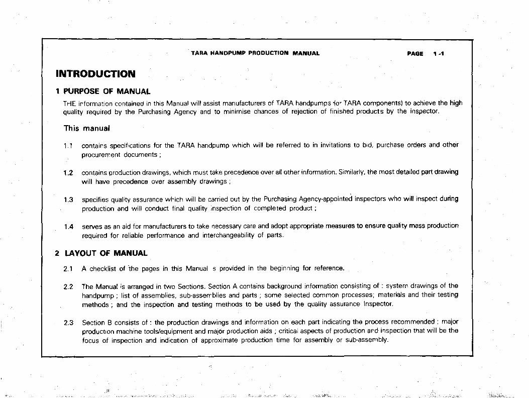
1 PURPOSE OF MANUALTHE information contained in this Manual will assist manufacturers of TARA handpumps -for TARA components) to achieve the highquality required by the Purchasing Agency and to minimise chances of rejection of finished products by the inspector.
This manual
1.1 contains specifications for the TARA handpump which will be referred to in invitations to bid, purchase orders and otherprocurement documents ;
1.2 contains production drawings, which must take precedence over all other information. Similarly, the most detailed part drawingwill have precedence over assembly drawings;
1.3 specifies quality assurance which will be carried out by the Purchasing Agency-appointed inspectors who will inspect duringproduction and will conduct final quality inspection of completed product;
1.4 serves as an aid for manufacturers to take necessary care and adopt appropriate measures to ensure quality mass productionrequired for reliable performance and interchangeability of parts.
2 LAYOUT OF MANUAL
2.1 A checklist of the pages in this Manual is provided in the beginning for reference.
2.2 The Manual is arranged in two Sections. Section A contains background information consisting o f : system drawings of thehandpump; list of assemblies, sub-assemblies and parts ; some selected common processes; materials and their testingmethods ; and the inspection and testing methods to be used by the quality assurance Inspector.
2.3 Section B consists of: the production drawings and information on each part indicating the process recommended ; majorproduction machine tools/equipment and major production aids ; criticai aspects of production and inspection that will be thefocus of inspection and indication of approximate production time for assembly or sub-assembly.
TARA HANDPUMP PRODUCTION MANUAL PAGE 1-2
INTRODUCTION
SYSTEM DRAWINGS AND GENERAL PROCESS INFORMATION
3.1 SYSTEM DRAWINGS
These drawings present an overview of the handpump system.
3.2 LIST OF ASSEMBLIES, SUB-ASSEMBLIES AND PARTS
The list shows name of assemblies, sub-assemblies and parts along with respective part numbers.
3.3 SELECTED COMMON PROCESSES
Some common processes have been selected, for ready reference, on the basis of their frequent applications and othersbecause of their special significance in the manufacture of TARA handpumpsThe Standards mentioned against these processesshould be followed to maintain high level of quality in the manufacture of the parts of the handpump. The numbers of thoseparts affected by these processes are also indicated. A list of major production tools/equipment and major production aids (asindicated in the, production informaton sheets) has been provided.
3.4 MATERIALS AND THEIR TESTING METHODS
1. Materials should conform to the brands listed. Manufacturers wishing to use other brands must seek Prior approval of thePurchasing Agency.
2. The Purchasing Agency may require to see the manufacturer's Test Certificate of raw materials.
3.5 STANDARDS
British Standards (BS), as available at the time of preparation of this Manual, have been given preference. When a particular BSis not available other Standards such as ASTM, ISI, ISO etc, as available, have been indicated. Manufacturers may use otherequivalent Standards with the Prior approval of the Purchasing Agency.
TARA HANDPUMP PRODUCTION MANUAL PAGE 1-3
INTRODUCTION
3.6 MARKINGS
1. Markings of Parts and Assemblies
Where specified, the parts and assemblies should have clear permanent markings identifying the manufacturer's name,production batch number and the year.
2. Marking of Packages
The packages shall be marked with the name of the manufacturer, number of parts in the package, trade mark if any, andthe month and year of the manufacture.Detailed marking instructions will be specified in the bid documents and purchase orders.
3.7 PACKAGING
Detailed packaging insturctions will be specified in the bid documents and purchase orders.
3.8 MANUFACTURER'S IN-HOUSE INSPECTION AND TESTING
The manufacturers should assign their own inspectors for the selection and testing of materials and for in-process qualftycontrol of parts and asembles in order to minimise chances of rejection by the Purchasing Agency appointed quality assuranceInspector.
Names of persons responsible for in-house quality control should be submitted to the Purchasing Agency on request.
3.9 QUALITY ASSURANCE
For the purpose of quality assurance the Purchasing Agency will appoint an independent inspection agency who will inspect andtest materials, Jigs, fixtures and gauges, work in process, finished parts, sub-assemblies and assemblies and conduct suchother tests as may be prescribed by the Purchasing Agency for the manufacturers. The independent inspectors will conducttests from samples to be provided by the manufacturers and the tests should be done in accordance with the Standardsprescribed.
TARA HANDPUMP PRODUCTION MANUAL PAGE 1 -4
INTRODUCTION
4 PRODUCTION INFORMATION AND DRAWINGS
4.1 PRODUCTION INFORMATION
1. Production process sequence, production machine tools/equipment, and production aids described in the 2nd, 3rd and 4thcolumns of the production information sheets are guidelines only and are not mandatory.
2. Critical aspects of production and inspection described in the 5th column of the production information sheets must bestrictly followed by the manufacturers.
3 Production Aids
The manufacturers of parts and assemblies should be equipped with all necessary production aids. Jigs and gaugesshould be so made that these shall be of ten (10) times the accuracy of the product. Jigs and fixtures should be calibratedperiodically and gauges in regular use checked periodically against their master gauges. Jigs, fixtures and gauges aresubject to inspection by an independent inspector appointed by the Purchasing Agency.
4. Production Time
In the production information sheets "Approx production time.... minutes" is supplied as guideline only. This timeincludes manufacturing time of all the relevant parts of a sub-assembly or an assembly and their assembling time.

TARA HANDPUMP PRODUCTION MANUAL PAGE 1 ~6
INTRODUCTION
4.2 DRAWINGS
The TARA handpump consists of over fifty parts. Several parts make a sub-assembly.There are thirteen sub-assemblies and eight assemblies.
2 Each assembly, sub-assembly and part has a part number; the part number is the same as the drawing number. The firstdigit of a part number corresponds to an assembly. The first digit after the decimal corresponds to a sub-assembly. Thesecond digit after the decimal corresponds to the number of the individual part. Thus, the assemblies (and drawings) in theTARA handpump are identified as 1.00, 2.00... 8.00; sub-assemblies (and drawings) are identified by numbers such as1.10, 1.20 4.10,4.20 etc ; and parts (and drawings) are identified by numbers such as 1.11.1.12....1.14, or 2.11,2.12etc. .
3 Tolerances shown in the drawings are in millimetres unless otherwise specified.
4 Precedence of drawings : the most detailed drawing is to be followed and drawings take precedence over otherinformation.
5 Parts shall be manufactured of specified materials and to dimensions, tolerances and surface finish as specified in thedrawings and production information
6 Finished sub-assemblies and assemblies should be exclusively as per the drawings and production information.Dimensions, tolerances, classes of fit, alignments, concentricity and the quality of finish should be as specified.
7 In the event of a revision of a drawing, the manufacturers should adhere to relevant changes that might occur in material,standards, dimensions, tolerances, classes of fit, alignments, concentricity, quality of finish and other specification.
5 AMENDMENTSThe Manual allows Provision for incorporating future amendments, for which amendment record sheets
are provided. (see end of Manual)
TARA HANDPUMP PRODUCTION MANUAL PAGE A 0
SECTION A
SYSTEM DRAWINGS
AND GENERAL PROCESS INFORMATION
TARA HANDPUMP PRODUCTION MANUAL P A G E A1 0
SYSTEM DRAWINGS
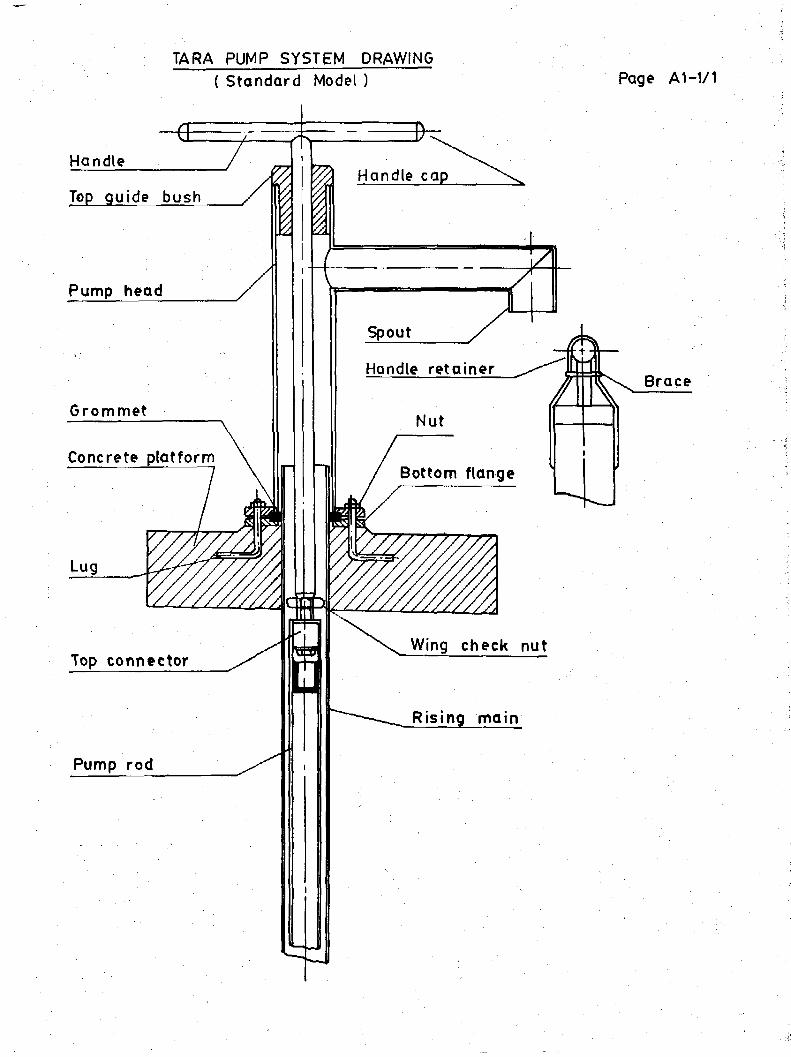
TARA PUMP SYSTEM DRAWING( Standard Model ) Page A1-1/1
Handle capTop guide bush
Pump head
Handle retainer
Grommet
Concrete platformBottom flange
Wing check nutTop connector
Rising main
Pump rod
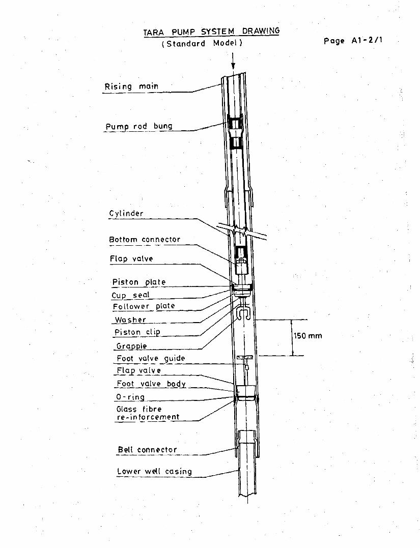
TARA PUMP SYSTEM DRAWING(Standard Model) page A1-2/1
Rising main
Pump rod bung
Cylinder
Bottom connector
Flap valve
Piston plate
Cup sealRajjower plate
WasherPiston cljp
Grapple.
Glass fibrere-inforcement
Bell connector
Lower well casing
Foot valve guide
Flap valve
Foot valve body
0- ring __
150 mm
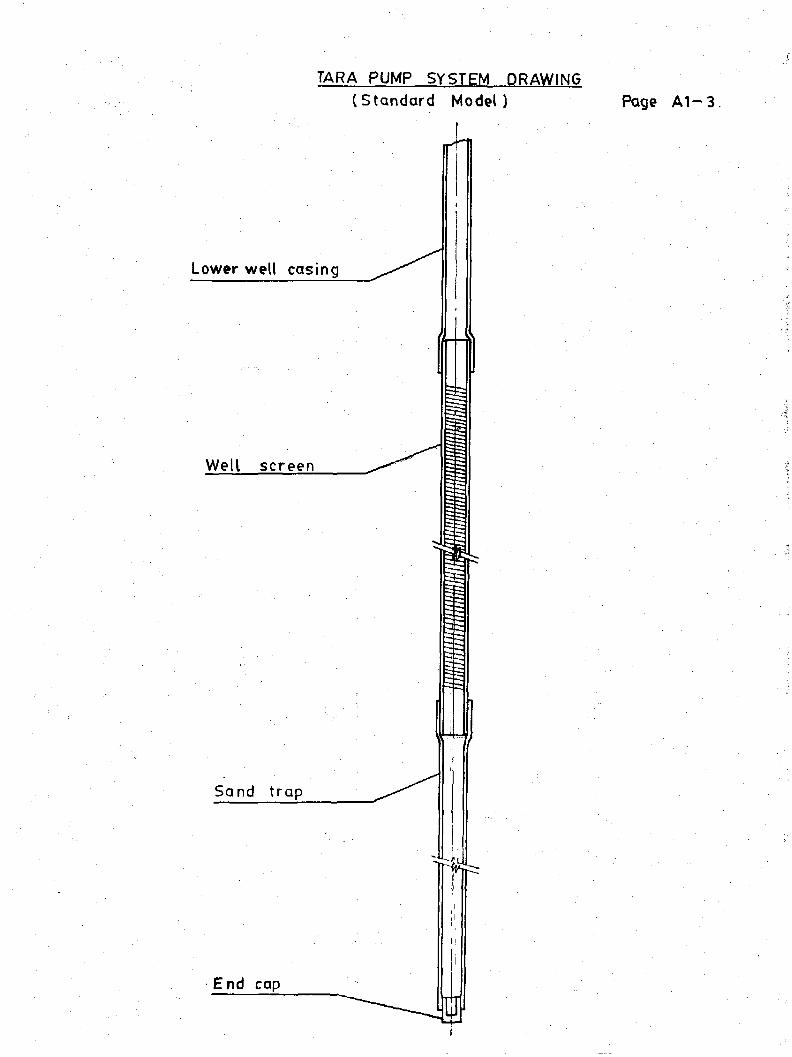
TARA PUMP SYSTEM DRAWING(Standard Model) Page A1-3
Lower well casing
Well screen
Sand trap
End cap
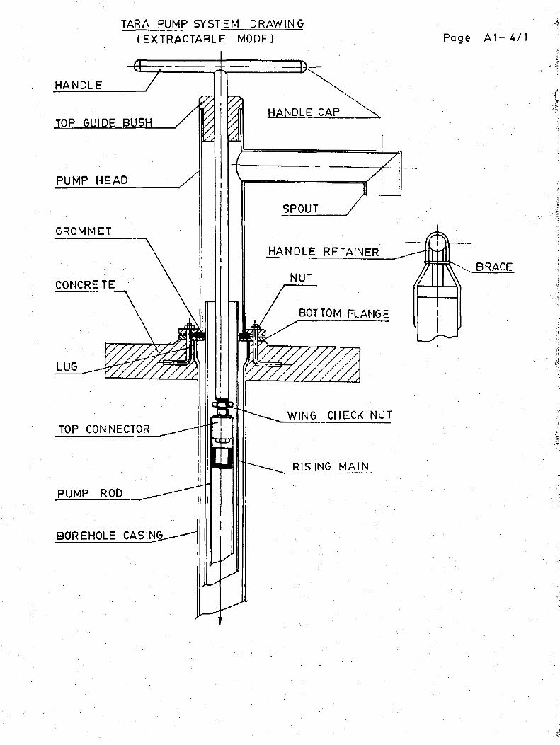
TARA PUMP SYSTEM DRAWING(EXTRACTABLE MODE) Page A 1 - 4 / 1
HANDLE CAPTOP GUIDE BUSH
PUMP HEAD
GROMMET
HANDLE RETAINER
NUTCONCRETE
BOTTOM FLANGE
WING CHECK NUTTOP CONNECTOR
RISING MAIN
PUMP ROD
BOREHOLE CAS1N&-—-^
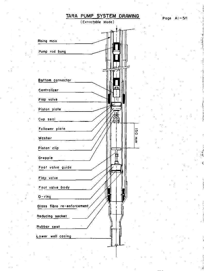
TARA PUMP SYSTEM DRAWING(Extroctable Mode)
Rising main
Pump rod bung
Bottom connector
Centralizer
Flap valve
Piston plate
Cup seal
Follower plate
Washer
Piston clip
Grapple
Foot valve guide
Flap valve
Foot valve body
0 - ring
Glass fibre re-enforcement
Reducing socket
Rubber seat
Lower well casing
Page AI -5 /1

TARA PUMP SYSTEM DRAWING(Extractable Model) Page A1-6
Lower well casing
Well screen
Sgnd trap
End cap
n
TARA HANOPUMP PRODUCTION MANUAL PAGE A2 0
• .
LIST OF ASSEMBLIES,
SUB-ASSEMBLIES
AND PARTS
PART NUMBER :
NAME
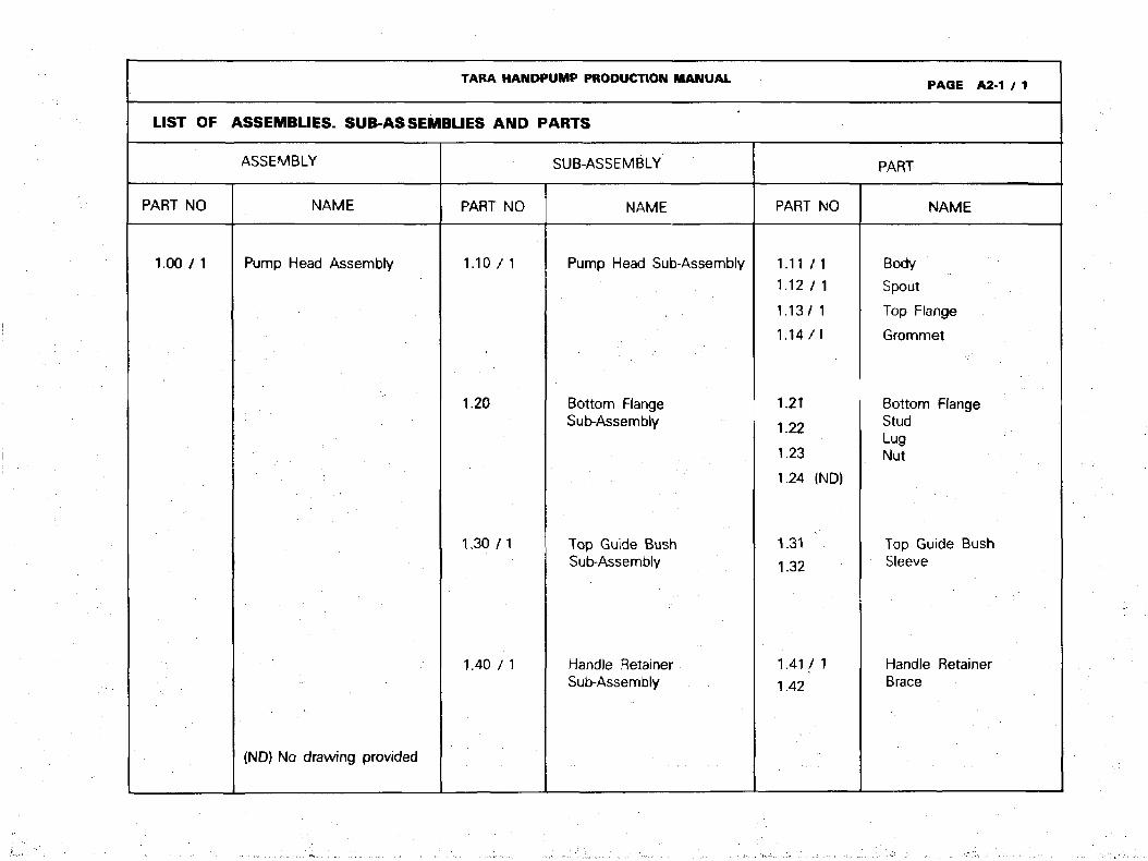
TARA HANDPUMP PRODUCTION MANUAL
LIST OF ASSEMBLIES. SUB-ASSEMBLIES AND PARTS
ASSEMBLY
PART NO
1.00/ 1
NAME
Pump Head Assembly
{ND} No drawing provided
SUB-ASSEMBLY
PART NO
1.10 / 1
1.20
1.30 / 1
1.40 / 1
NAME
Pump Head Sub-Assembly
Bottom FlangeSub-Assembly
Top Guide BushSub-Assembly
Handle RetainerSub-Assembly
PAGE A2-1 / 1
PART
PART NO
1.11 /I1.12 / 1
1.13/ 1
1.14/1
1.21
1.22
1.23
1.24 (ND)
1.31
1.32
1.41/1
1.42
NAME
Body
Spout
Top Flange
Grommet
Bottom FlangeStudLugNut
Top Guide BushSleeve
Handle RetainerBrace

TARA HANDPUMP PRODUCTION MANUAL PAGE A2-5 / 1
LIST OF ASSEMBLIES. SUB-ASSEMBLIES AND PARTS
ASSEMBLY
PART NO
7.00 (ND)
8.00
NAME
Tubewell Assembly
Retrieving RodAssembly
ND= NO drawingprovided
SUB-ASSEMBLY
PART NO
7.10
7.20
NAME
Upper TubewellSub-Assembly
Lower TubewellSub-Assembly
PART
PART NO
7.11 (ND)7.12(ND)7.13/1
7.15/1
7.21 (ND)7.227.23 (ND)7.24
8.1KND)8.12(ND)
NAME
2" Rising Main3" Upper Well Casing*Rising Main Centralizer*(7.14 Deleted)Reducing Socket*
1.5" Lower Well CasingWell ScreenSand TrapEnd Cap
RodNut
*For extractable mode only

LIST OF
TARA HANDPUMP PRODUCTION MANUAL
ASSEMBLIES. SUB-ASSEMBLIES AND
ASSEMBLY
PART NO
2.00 n
3.00 / 1
NAME
Handle Assembly
Pump Rod Assemblywith Top Connector
. • • • - - •
ND = No drawing provided
PART NO
3.10/1
3.20 (ND)
PARTS
SUB-ASSEMBLY
NAME
Top ConnectorSub-Assembly
Pump Rod Sub-Assembtv
PART NO
2.11 / 1
2 .12 /1
2 13
2.14
3.113.12 / 13.13
3.15
3.17
3.21 (ND)3.22 / 1
PAGE A2-2 / 1
PART
NAME
RodHandleHandle NutHandle Cap
Top Connector BushBoltWasher(3.14 Deleted)Nut(3.16 Deleted)Wing Check Nut
Pump RodPump Rod Bung(3.23 Deleted)

TARA HANDPUMP PRODUCTION MANUAL
LIST OF ASSEMBLIES. SUB-ASSEMBLIES AND PARTS
ASSEMBLY
PART NO
4.00 / 1
NAME
Piston Assembly withBottom Connector
ND=No drawing Provided
SUB-ASSEMBLY
PART NO
4.10
4.20/1
4.30
NAME
Bottom ConnectorSub-Assembly
Piston Sub-Assembly
Grapple Sub-Assembly
PAGE A2-3 / 1
PART
PART NO
4.11/14.124.134.14 (ND)
4.21
4.22
4.234.24
4.26 / 1
4.314.324.33/1
NAME
Bottom Connector BushConnector RodNutWasher (same as 3.13)
Flap Valve (Piston)Piston PlateFollower PlateWasher(4.25 Deleted)
Cup Seal Leather
Grapple BushHookPiston Clip

TARA HANDPUMP PRODUCTION MANUAL
UST OF ASSEMBLIES. SUB-ASSEMBLIES AND PARTS
ASSEMBLY
PART NO
5.00
6.00 / 1
NAME
Food valve Assembly
Cylinder Assembly
ND=NO drawing Provided
SUB-ASSEMBLY
PART NO
5.10 (ND}
5.20
NAME
Foot Valve BodySub-Assembly
Foot Valve GuideSub-Assembly
PAGE A2-4 / 1
PART
PART NO
5.115.125.135.14/ 1
5.215.225.235.24
6.116.126.13
NAME
1
Foot Valve BodyBoltFlap Valve (Foot Valve)0 Ring
Guide RodRodGuideFoot Valve Guide Bush
Cylinder PipeBell ConnectorRubber Seat*
* For Extractable mode only.
TARA HANDPUMP PRODUCTION MANUAL PAGE A3 0
SELECTED
COMMON PROCESSES
STANDARDS
GENERAL REMARKS

TARA HANDPUMP PRODUCTION MANUAL PAGE A3-1
SELECTED COMMON PROCESSES LIST OF MAJOR PRODUCTION TOOLS / EQUIPMENT AND AIDS
Major production Tools / Equipment
1 Electric arc welder (minimum 180A)2 Hand grinder machine3 Hot dip galvanizing bath4 Reciprocating Saw5 Band Saw6 Circular Saw machine7 Lathe machine8 Radial Drill machine9 Milling machine10 Oxy acetylene gas cutting equipment11 Drilling machine12 Mixing roller13 Press machine14 Die mould15 Reversible tapping chuck16 Press machine (bench type)17 Wood turning lathe18 Shearing machine19 Bending roller machine20 Oxy acetylene gas welding equipment21 Shearing press or iron worker22 Heat treatment oven
NB. Items have been listed above in the
23 Bench grinding machine24 Punching press (bench type)25 Zinc electroplating equipment26 Combination die27 Forming die28 Injection moulding machine29 Punching press30 Metal cutting machine31 Pedestal grinder32 Ball press33 Bending die34 Hack saw35 Heating equipnnent36 Crimping die37 Flaring die38 PVC extrusion plant39 Bell socket forming die40 Slitting saw attachment41 Hand injection moulding machine
Major Production Aids
1 Drill jig2 Welding jig3 Non-slip assembly welding jig4 Sawing jig5 Plug gauge6 Milling fixtures7 Circular guide for gas cutting8 Go, not go snap gauge9 Ring gauge for threaded external
diameter10 Bending jig11 Cylindrical mandrel12 Go,not go thread plug gauge13 Ring gauge14 Snap gauge15 Go, not go plug gauge16 Dial gauge indicator17 Thread gauge18 Form pipe (mandrel)19 Non-slip welding jig20 Thread plug gauge21 Feeler gauge ' :
; order in which they appear in the production information sheets.
TARA HANDPUMP PRODUCTION MANUAL A3-2 / 1
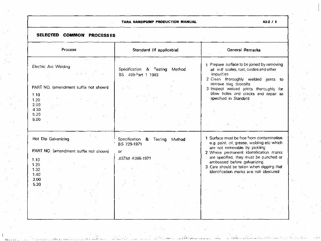
SELECTED COMMON PROCESSES
Process
Electric Arc Welding
PART NO. (amendment suffix not shown)
1.101.202.004.305.208.00
Hot Dip Galvanizing
PART NO. (amendment suffix not shown)
1.101.201.321.402.005.20
Standard (if applicable)
Specification & Testing MethodBS 499-Part 1 1983
Specification & Testing MethodBS 729-1971
or
ASTM A386-1971
General Remarks
1 Prepare surface to be joined by removingail mill scales, rust, oxides and otherimpurities
2 Clean thoroughly welded joints toremove slag deposits
3 Inspect welded joints thoroughly forblow holes and cracks and repair asspecified in Standard
1 Surface must be free from contaminatione.g. paint, oil, grease, welding etc whichare not removable by pickling
2 Where permanent identification marksare specified, they must be punched orembossed before galvanizing
3 Care should be taken when dipping thatidentification marks are not obscured
TARA HANDPUMP PRODUCTION MANUAL PAGE A3-3 / 1
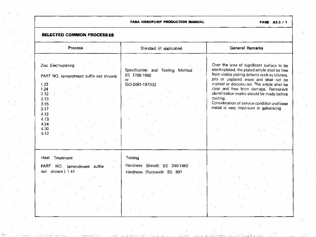
SELECTED COMMON PROCESSES
Process
Zinc Electroplating
PART NO. (amendment suffix not shown)
1.221.243.12 . : ;3.133.153.174.124.134.244.305 . 1 2 : • • • • • •
Heat Treatment
PART NO. (amendment suffixnot shown) 1.41
Standard (if applicable)
Specification and Testing MethodBS 1706-1960orISO-2081-1973(E)
Testing
Hardness (Brinell) BS 240-1962
Hardness (Rockwell) BS 891
General Remarks
Over the area of significant surface to beelectroplated, the plated article shall be freefrom visible plating defects such as blisters,pits or unplated areas and shall not bestained or discoloured. The article shall beclear and free from damage. Permanentidentification marks should be made beforecoating.Consideration of service condition and basemetal is very important in galvanizing
TARA HANDPUMP PRODUCTION MANUAL PAGE A3-4 / 1
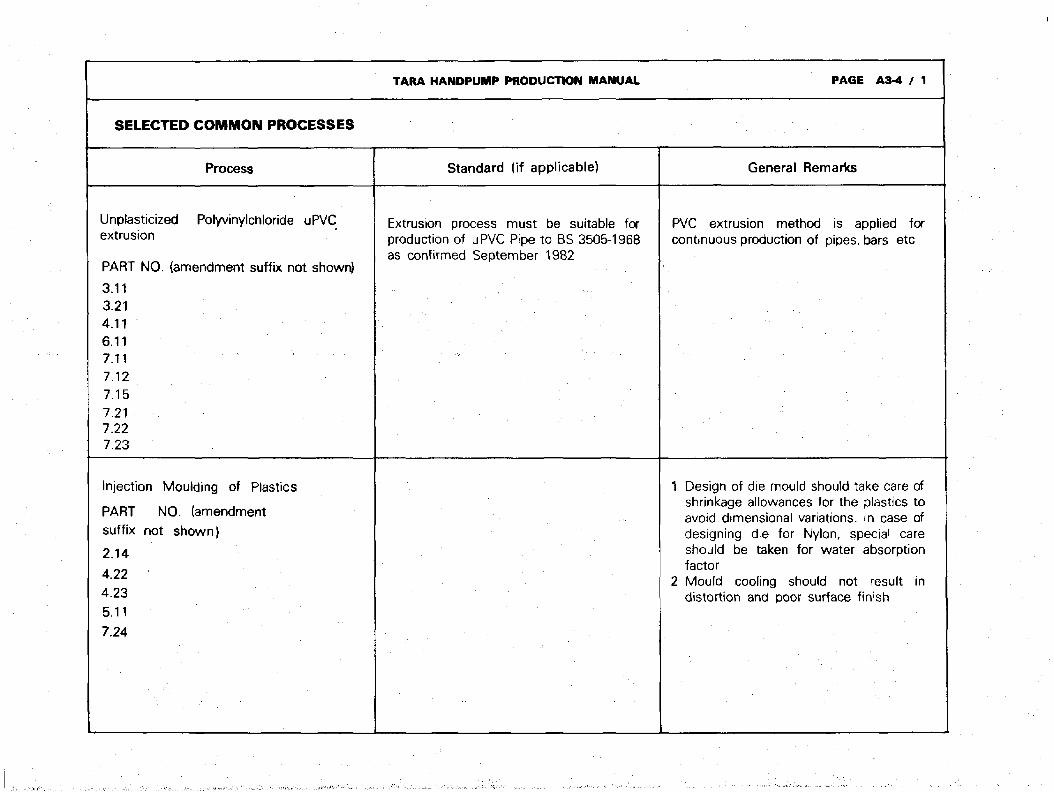
SELECTED COMMON PROCESSES
Process Standard (if applicable) General Remarks
Unplasticizedextrusion
Polyvinylchloride uPVC
PART NO. (amendment suffix not shown)
3.113.214.116.117.117.127.157.217.227.23
Extrusion process must be suitable forproduction of uPVC Pipe to BS 3505-1968as confirmed September 1982
PVC extrusion method is applied forcontinuous production of pipes, bars etc
Injection Moulding of Plastics
PART NO. (amendmentsuffix not shown}
2.14
4.22
4.23
5.11
7.24
Design of die mould should take care ofshrinkage allowances for the plastics toavoid dimensional variations. In case ofdesigning die for Nylon, special careshould be taken for water absorptionfactorMould cooling should not result indistortion and poor surface finish
TARA HANDPUMP PRODUCTION MANUAL PAGE A3-5 / 1
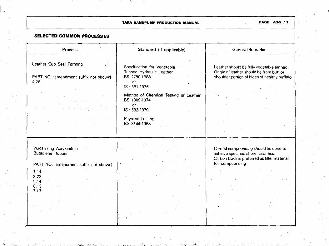
SELECTED COMMON PROCESSES
Process
Leather Cup Seal Forming
PART NO. (amendment suffix not shown)4.26
Vulcanizing AcrylonitrileButadiene Rubber
PART NO. (amendment suffix not shown)
1.143.225.146.137.13
Standard {if applicable)
Specification for VegetableTanned Hydraulic LeatherBS 2780-1983
orIS : 581-1976
Method of Chemical Testing of LeatherBS 1309-1974
orIS: 582-1970
Physical TestingBS 3144-1968
General Remarks
Leather should be fully vegetable tanned.Origin of leather should be from butt orshoulder portion of hides of healthy buffalo
Careful compounding should be done toachieve specified shore hardness.Carbon black is preferred as filler materialfor compounding
TARA HANDPUMP PRODUCTION MANUAL PAGE A4-0
- •
MATERIALS
AND THEIR
TESTING METHODS
RECOMMENDED BRAND
STANDARD
GENERAL REMARKS :
• • .
MATERIALS ANE
MildPlate;
PARTsuffix1.131.211.221.231.322.13
Mild I
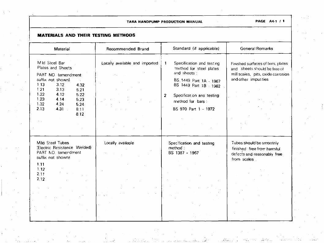
Material
Steel Bar> and Sheets
TARA HANDPUMP
» THEIR TESTING METHODS
NO. (amendmentnot shown)
3.123.134.124.144.244.31
Steel Tubes(Electric ResistancePARTsuffix
1.111.122.112.12
4.325.215.225.235.248.118.12
Welded)NO. (amendmentnot shown)
Recommended Brand
Locally available and imported
Locally available
PRODUCTION MANUAL
Standard (if applicable)
1 Specification and testingmethod for steel platesand sheets :
BS 1449 Part 1A - 1967BS 1449 Part 1B - 1962
2 Specification and testingmethod for bars :
BS 970 Part 1 - 1972
Specification and testingmethod :BS 1387 - 1967
PAGE A4-1 / 1
General Remarks
Finished surfaces of bars, platesand sheets should be free ofmill scales, pits, oxide corrosionand other impurities
Tubes should be smoothlyfinished free from harmfuldefects and reasonably freefrom scales
TARA HANDPUMP PRODUCTION MANUAL PAGE A4-2 / 1
MATERIALS AND THEIR TESTING METHODS
Material
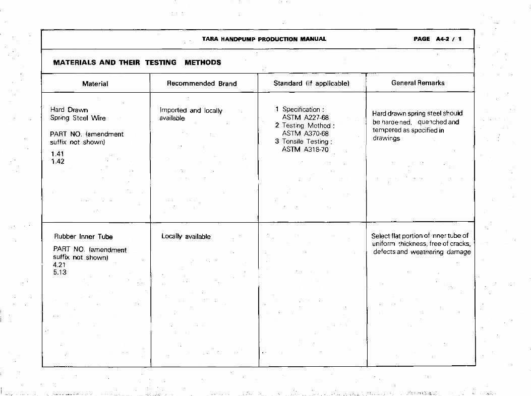
Hard DrawnSpring Steel Wire
PART NO. (amendmentsuffix not shown}
1.411.42
Rubber Inner Tube
PART NO. (amendmentsuffix not shown)4.215.13
Recommended Brand
Imported and locallyavailable
Locally available
Standard (if applicable)
1 Specification :ASTM A227-68
2 Testing Method :ASTM A370-68
3 Tensile Testing :ASTM A318-70
General Remarks
Hard drawn spring steel shouldbe hardened, quenched andtempered as specified indrawings
Select flat portion of inner tube ofuniform thickness, free of cracks,defects and weathering damage
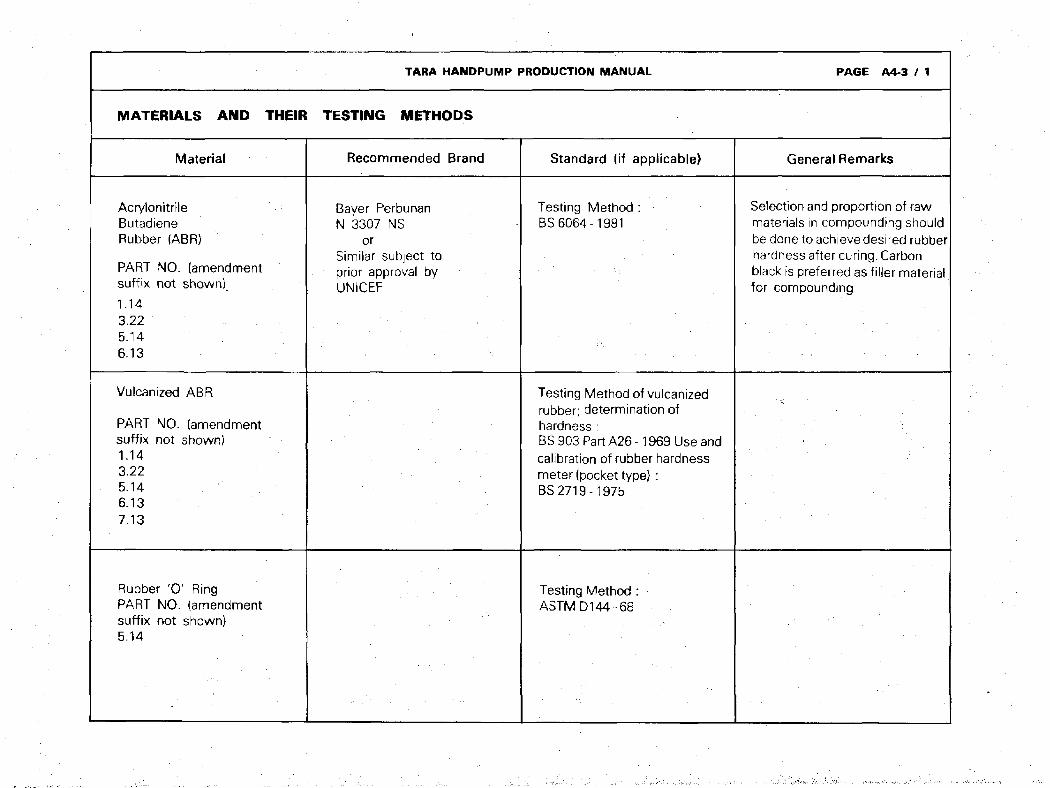
TARA HANDPUMP PRODUCTION MANUAL PAGE A4-3 / 1
MATERIALS AND THEIR
Material
AcrylonitrileButadieneRubber (ABR)
PART NO. (amendmentsuffix not shown).1.143.225.146.13
Vulcanized ABR
PART NO. (amendmentsuffix not shown)1.143.225.146.137.13
Rubber '0 ' RingPART NO. (amendmentsuffix not shown)5.14
TESTING METHODS
Recommended Brand
Bayer PerbunanN 3307 NS
orSimilar subject toprior approval byUNICEF
Standard (if applicable)
Testing Method :BS 6064-1981
Testing Method of vulcanizedrubber; determination ofhardness :BS 903 Part A26 -1969 Use andcalibration of rubber hardnessmeter (pocket type} :BS 2719-1975
Testing Method :ASTMD144-68
•
General Remarks
Selection and proportion of rawmaterials in compounding shouldbe done to achieve desired rubberhardness after curing. Carbonblack is preferred as filler materialfor compounding

TARA HANDPUMP
MATERIALS AND THEIR TESTING METHODS
Material
Plastics
High DensityPolyethlene (HDPE)PART NO. (amendmentsuffix not shown)5.11
Polyamide (Nylon)
PART NO. (amendmentsuffix not shown)4.224.23
uPVC CompoundPART NO. (amendmentsuffix not shown)7.24
Rocommended Brand
Lupolen5261z (BASF)Lupolen6031M (BASF)Vestolene (Bayer)Hostallen Gur412 (HoechsDAlkathane (ICI)
ursimilar subject to priorapproval by UNICEF
Durathan BKV-35H (Bayer)Durathan 840SK (Bayer)Vestamid (Bayer)Zytel (Dupont)Maranyl (jci)
orsimilar subject to priorapproval by UNICEF
imported or locallyavailable
PRODUCTION MANUAL
Standard (if applicable)
Testing Method :BS 2782Part 1, 2, 3, 4, 6, 8, 9
•
•
• . • .
Specification andTesting Method :BS 2571 - 1963
PAGE A4-4
General Remarks
Synthetic plastic resins should becarefully combined, compounded,or chemically added withplastisizers, stabilizers, fillers.colourants and reinforcing agentsbefore processing
(a) HDPE is easily mouldablethermoplastic synthetic resin.Refer to manufacturers'specification
(b) Polyamides are easily mouldablethermoplastic synthetic resin.Nylon, most widely used ofpolyamides, is tough, strong, light,abrasion resistant, good chemicaland electrical resistant. It is highlywater absorbent. Refer tomanufacturers' specifications
(c) u PVC compound must beavailable for water grade pipemanufacture

TARA HANDPUMP PRODUCTION MANUAL
MATERIALS AND THEIR TESTING METHODS
uPVC
PARTsuffix"3 11>J. 1 1
3.214.116.116.12
Material
Pipe and bar stock
NO. (amendmentnot shown)
7 11/ . T 1
7.127.217.22
Recommended Brand
Locally available
• •
Standard (if applicable)
Specification and Testing Method:ForuPVC PipesBS 3505 - 1968 (1982)
1
2
3
4
5
6
7
8
9
PAGE A4-5
General Remarks
Check all dimensions toconform to specified tolerances
Internal surface for smoothfinish critical for cylinder pipe
Check for ovality
Check bell socket dimensionsand alignment with pipe
Pipes and bar stocks shouldbe of water grade. Check pipestraightness after extrusion
To avoid inducing bends inpipes during stacking,transportation and storing, maketight small bundles of pipeswith 50% of bells pointing onboth sides
Pipes should have markingsidentifying the manufacturerand Standard at regularintervals, as specified inpurchase orderThe above remarks also applyto manufacturers of pipes withinternal reinforcing ribs
Bar stock to be free from blowholes
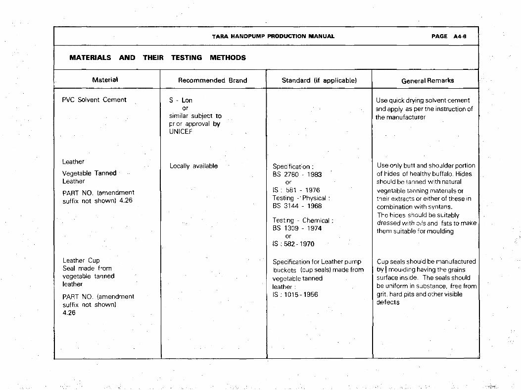
TARA HANDPUMP PRODUCTION MANUAL PAGE A4-6
MATERIALS AND THEIR TESTING METHODS
Material
PVC Solvent Cement
Leather
Vegetable TannedLeather
PART NO. (amendmentsuffix not shown) 4.26
Leather CupSeal made fromvegetable tannedleather
PART NO. (amendmentsuffix not shown)4.26
Recommended Brand
S - Lonor
similar subject toprior approval byUNICEF
Locally available
Standard (if applicable)
Specification :BS 2780 - 1983
orIS : 581 - 1976Testing -Physical :BS 3144 - 1968
Testing - Chemical:BS 1309 - 1974
orIS-582-1970
Specification for Leather pumpbuckets (cup seals) made fromvegetable tannedleather:IS : 1015-1956
General Remarks
Use quick drying solvent cementand apply as per the instruction ofthe manufacturer
Use only butt and shoulder portionof hides of healthy buffalo. Hidesshould be tanned with naturalvegetable tanning materials ortheir extracts or either of these incombination with syntans.The hides should be suitablydressed with oils and fats to makethem suitable for moulding
Cup seals should be manufacturedby | moulding having the grainssurface inside. The seals shouldbe uniform in substance, free fromgrit, hard pits and other visible
dfefects

TARA HANDPUMP PRODUCTION MANUAL PAGE A4-7 / 1
MATERIALS AND THEIR TESTING METHODS
Material
Hardwood
PART NO. (amendmentsuffix not shown)1.31
Hexagon Head Bolts and Nuts
PART NO. (amendmentsuffix not shown)1.24 4.133.15 5.123.17
Stainless Steel
PART NO. (amendmentsuffix not shown)4.33
Recommended Brand
Teak (Tectona grandis)or
Shal (Shorea Robusta)or
Shilkoroi (Albizia Lebbec)
Locally available and imported
Locally available or imported
Standard (if applicable}
BS 3692 - 1967or
ISO 4016 (1979) for boltsand
ISO 4034 (1979) for nuts
BS 2056 : 1983
General Remarks
Hardwood should be seasoned,finished surfaces to be free ofcracks and knots
Steel property class 4.6
TARA HANDPUMP PRODUCTION MANUAL PAGE A5-0
INSPECTION
AND
TESTING
MATERIAL
PRODUCTION PROCESS
ASSEMBLIES, SUB-ASSEMBLIES AND PARTS
•
TARA HANDPUMP PRODUCTION MANUAL PAGE A5-1
INSPECTION AND TESTING
1 MATERIAL
INSPECTION
External inspectors may check raw materials and standard products used in the manufacture of the Tara pumpagainst their specification and testing methods in accordance with the Standards mentioned in the third column of thesub-section "Materials and Their Testing Methods" and the relevant drawings. UNICEF may ask to see manufacturers'test certificates on raw materials and standard products.
TARA HANDPUMP PRODUCTION MANUAL
INSPECTION AND TESTING
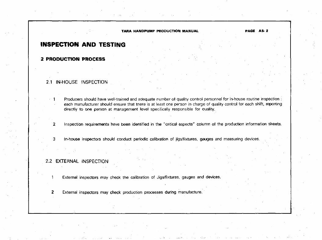
2 PRODUCTION PROCESS
2.1 IN-HOUSE INSPECTION
1 Producers should have well-trained and adequate number of quality control personneleach manufacturer should ensure that there is at least one person in charge of qualitydirectly to one person at management level specifically responsible for quality.
2 Inspection requirements have been identified in the "critical aspects" column of the
3 In-house inspectors should conduct periodic calibration of jigs/fixtures, gauges and
2.2 EXTERNAL INSPECTION
1 External inspectors may check the calibration of Jigs/fixtures, gauges and devices.
2 External inspectors may check production processes during manufacture.
PAGE AS-2
for in-house routine inspection :control for each shift, reporting
production information sheets.
measuring devices.

TARA HANDPUMP PRODUCTION MANUAL PAGE A5-3
INSPECTION AND TESTING
3.1 IN-HOUSE INSPECTION
1 Examine assemblies, sub-assemblies and parts visually for defects and finish.
2 Examine galvanized surface finish and painted surface finish for continuity, smoothness and adhesion. The surface shouldbe free of blemishes. Some samples may be tested for thickness of coating.
3 Inspect welded joints for blow holes, cracks and slag deposits.
4 Check alignment, concentricity and surface finish of assemblies and sub-assemblies.
5 Check critical dimensions as mentioned in the last column "critical aspects" of the production information sheets in thismanual.
6 Check parts made of hard drawn steel wire for spring elasticity.
7 Check thread formation and fits of relevant parts.
3.2 EXTERNAL INSPECTION
1 Sampling should be done to conform to standards BS 6001-72 and BS 6002-79.
2 Assemblies, sub-assemblies and parts should be properly inspected with regard to "critical aspects" and Standards.
3 Inspection should result in interchangeability of parts.

TARA HANDPUMP PRODUCTION MANUAL PAGE BO
SECTION B
PRODUCTION INFORMATION AND DRAWINGS
TARA HANDPUMP PRODUCTION MANUAL PAGE B1-0
1
PUMPHEADASSEMBLY
PRODUCTION INFORMATION
DRAWINGS
I
TARA HANDPUMP PRODUCTION MANUAL PRODUCTION INFORMATION PAGE B1-1
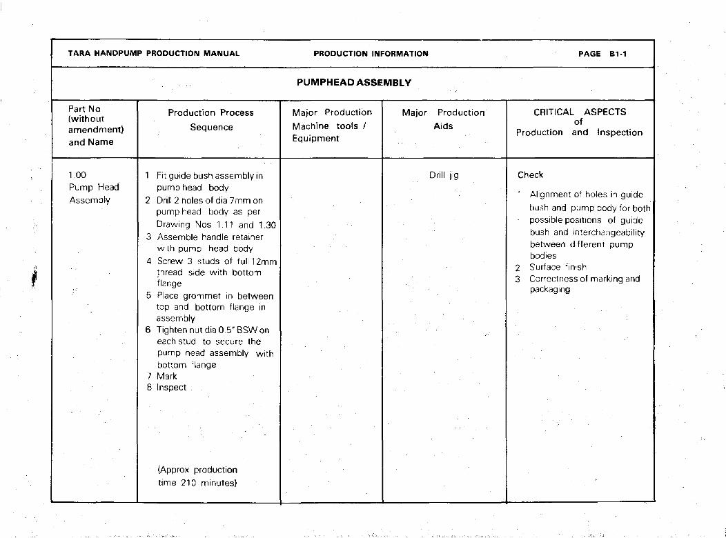
PUMPHEAD ASSEMBLY
Part No{ \AI i t Hi O 1 11\ Will IUUL
amendment)and Name
1.00Pump HeadAssembly
Production Process
Sequence
1 Fit guide bush assembly inpump head body
2 Drill 2 holes of dia 7mm onpump head body as perDrawing Nos 1.11 and 1.30
3 Assemble handle retainerwith pump head body
4 Screw 3 studs of full 12mmthread side with bottomflange
5 Place grommet in betweentop and bottom flange inassembly
6 Tighten nut dia 0.5" BSW oneach stud to secure thepump head assembly withbottom flange
7 Mark8 Inspect
(Approx productiontime 210 minutes)
Major Production
Machine tools /Equipment
Major ProductionAids
Drill jig
CRITICAL ASPECTSof
Production and Inspection
Check
1 Alignment of holes in guidebush and pump body for bothpossible positions of guidebush and tnterchangeabilitybetween different pump
bodies2 Surface finish3 Correctness of marking and
packaging

TARA HANDPUMP 1QUANTITY MATERIAL CUTOFF SIZE
DPHE
SCALE
1 : 2TOLERANCEU. 0. S±. 0-5
DATE
21. 1 . 87
NAME :
PUMPHEAD ASSEMBLY
PART NO.
1.00/1

I M M I I I ' M M M 1 > \ > M M i I I I M I I II I 1 I I I < I
TARA HANDPUMP PRODUCTION MANUAL
PUMP HEAD
Part No
(withoutamendment)and Name
1.10Pump HeadSub-Assembly
ASSEMBLY
Production ProcessSequence
1 Fix. inner pipe and endpipe in Sub-assembly jigand weld (to make spout)
2 Weld flange top with body
3 Fix spout and flanged bodyin assembly jig and tackweld
4 Final weld
5 Grind :i
6 File
7 Hot dip galvanize
8 Inspect
{Approx productiontime 70 minutes)
PRODUCTION INFORMATION
PUMP HEAD SUB-ASSEMBLY
Major ProductionMachine Tools /Equipment
1 Electric arc welder(minimum 180A)
2 Hand grinder
Machine3 Hot dip galvanizing
L-iL
bath
Major ProductionAids
1 Welding jig for spout2 Non-slip assembly
welding jig for
complete pump :head assembly
PAGE B1-2
CRITICAL ASPECTSof
Production and Inspection
Check
1 Spout aliqnment so that• ^ ^ p»* ^»* ^ " * fe^ I q ^j I I • • • ^ ^ i I ^ KJ^S ^ 1 1 \Jt V
inner pipe and end pipeare at 90°
2 Alignment of top flangeand spout with body so thatafter welding flange andspout are at 90° with bodyand spout end pipe is inline with body
3 Flange hole locations toconform to drawing
4 Surface finish
I H » U ' ' ' > I ' ' > ( > ( f I 1 I ' M M 1 t
TARA HANDPUMP PRODUCTION MANUAL
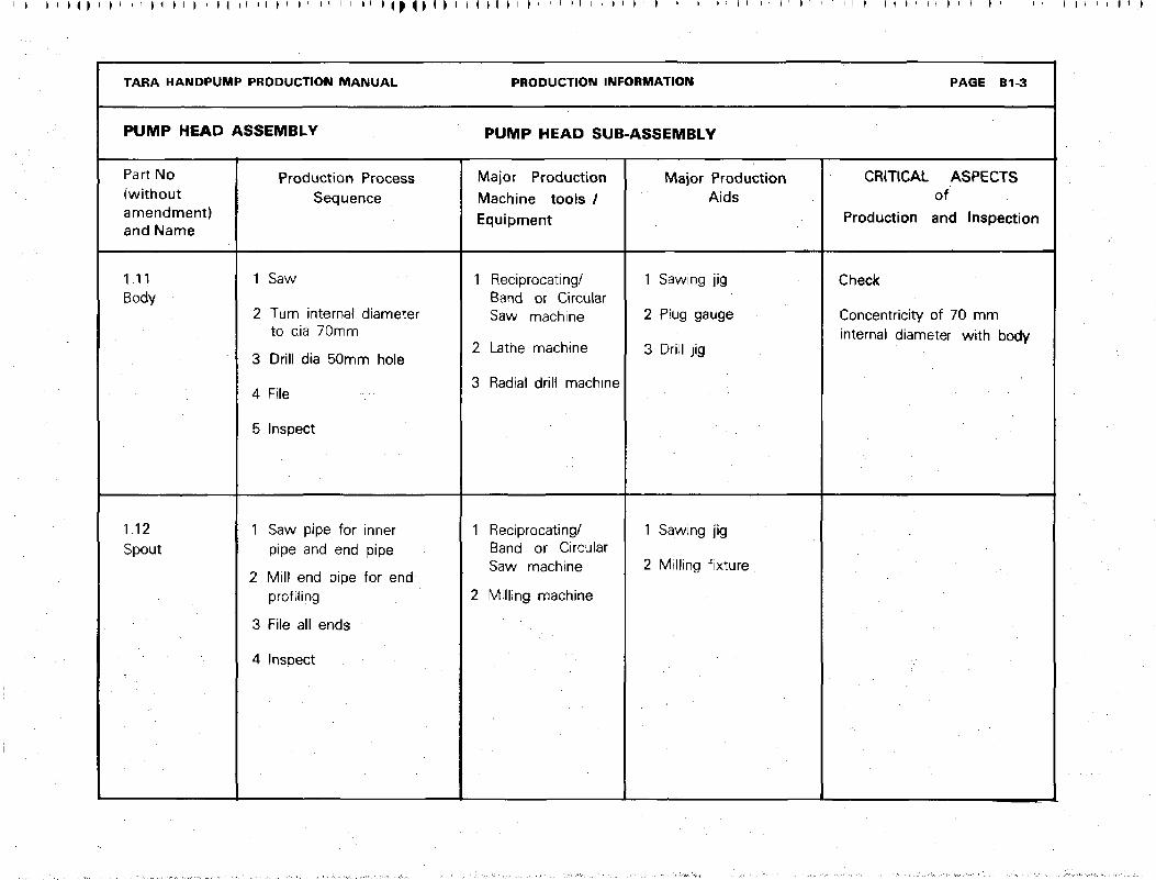
PUMP HEAD ASSEMBLY
Part No(withoutamendment)and Name
1.11Body
1.12Spout
Production ProcessSequence
1 Saw
2 Turn internal diameterto dia 70mm
3 Drill dia 50mm hole
4 File
5 Inspect
1 Saw pipe for innerpipe and end pipe
2 Mill end pipe for endprofiling
3 File all ends
4 Inspect
PRODUCTION INFORMATION
PUMP HEAD SUB-ASSEMBLY
Major Production
Machine tools /
Equipment
1 Reciprocating/Band or CircularSaw machine
2 Lathe machine
3 Radial drill machine
1 Reciprocating/Band or CircularSaw machine
2 Milling machine
Major ProductionAids
1 Sawing jig
2 Plug gauge
3 Drill jig
1 Sawing jig
2 Milling fixture
PAGE B1-3
CRITICAL ASPECTSof
Production and Inspection
Check
Concentricity of 70 mminternal diameter with body

M I ' ) < M M I I ) ' M I ' I I i M
TARA HANDPUMP PRODUCTION MANUAL PRODUCTION INFORMATION PAGE B1-4 / 1
PUMP HEAD ASSEMBLY PUMP HEAD SUB-ASSEMBLY
Part No(withoutamendment}and Name
Production Processsequence
Major ProductionMachine Tools /Equipment
Major Production
Aids
CRITICAL ASPECTSof
Production and Inspection.
1.13
Top Flange
1 Cut blanks from MSplates by Oxyacetylene gas
2 Turn
3 Bore
4 Drill holes
5 Inspect
1 Oxy acetylene gascutting equipment
2 Lathe machine
3 Drilling machine
1 Circular guidefor gas cutting
2 Drill jig
Check
1 Drilling of 3x14mm holesequispaced on PCD 120mm
2 Location of 3 holes in relationto the body and directionof spout
3 Surface finish smooth
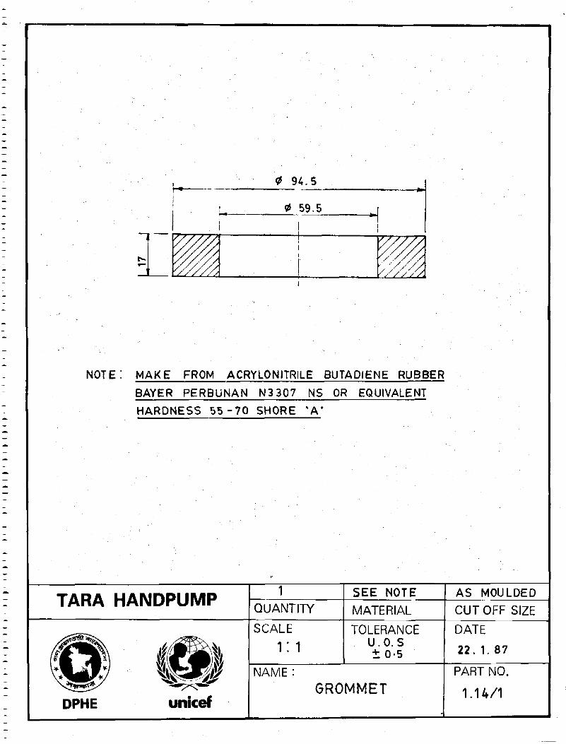
1.14Grommet
1 Compound and roll rubberdough into sheets
2 Mould and vulcanize
3 Inspect
1 Mixing roller
2 Press machine
3 Die moufd
Check
1 Hardness 55-70 Shore "A"
2 Moulded dimensions
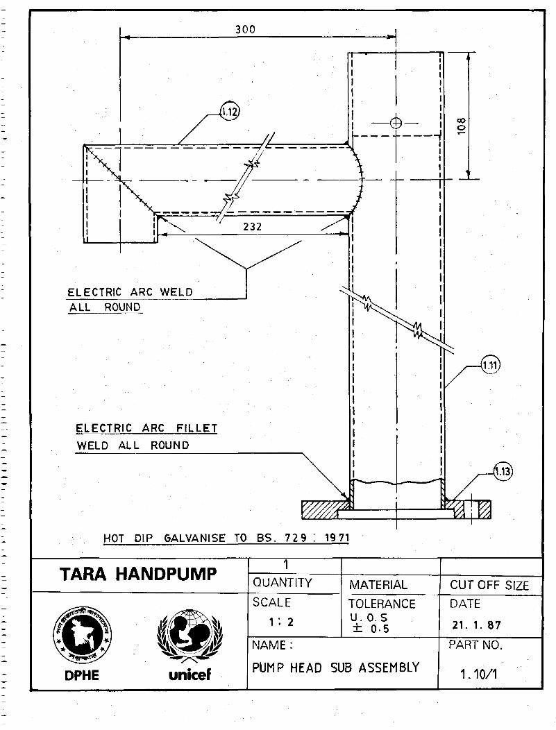
300
ELECTRIC ARC WELD
ALL ROUND
ELECTRIC ARC FILLET
WELD ALL ROUND
HOT DIP GALVANISE TO BS. 729 : 19 71
TARA HANDPUMPQUANTITY MATERIAL CUTOFF SIZESCALE
1 : 2
TOLERANCEU.O. S± 05
DATE
21. 1. 87
DPHE unicef
NAME:
PUMP HEAD SUB ASSEMBLY
PART NO.
1.10/1
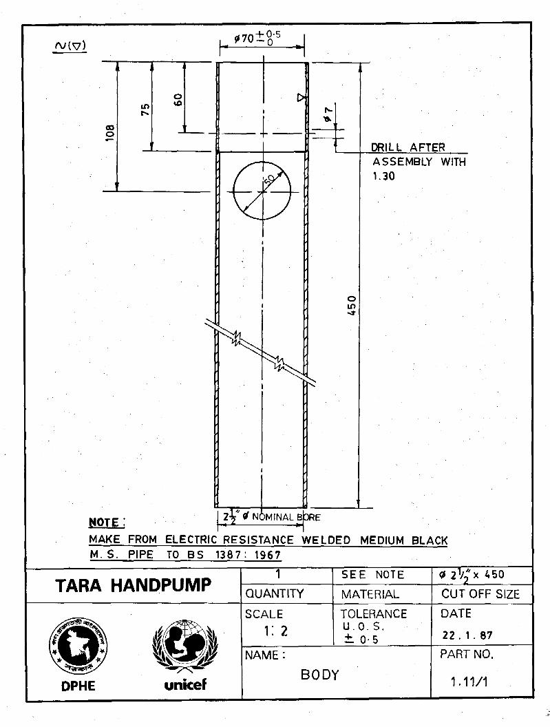
108
NOTE
in
_
o
•
L- r ' v --0r
0
2V' * NOMINAL B
1 **•
s
3RE
45
0
DRILL AFTERASSEMBLY WITH1.30
MAKE FROM ELECTRIC RESISTANCE WELDED MEDIUM BLACKM. S^PIPE TO BS 1387: 1967
2V"* 450TARA HANDPUMP
1QUANTITY
SEE NOTE
MATERIAL CUT OFF SIZE
SCALE
i: 2TOLERANCEU.O.S.± 0-5
DATE
22 . 1 . 87
NAME:
DPHE unicefBODY
PART NO.
1.11/1
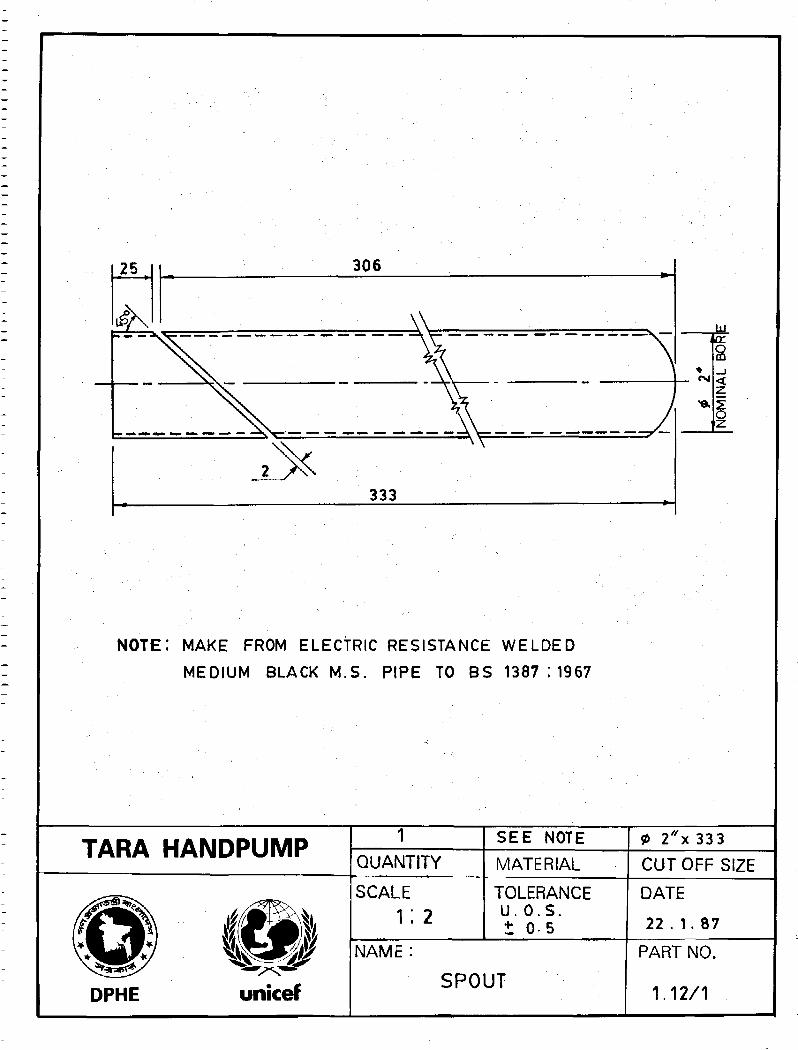
NOTE; MAKE FROM ELECTRIC RESISTANCE WELDED
MEDIUM BLACK M.S. PIPE TO BS 1387:1967
TARA HANDPUMP 1QUANTITY
SEE NOTE
MATERIAL
2"x 333
CUT OFF SIZE
fitDPHE
1-unicef
SCALE
1:2TOLERANCEU.O.S .+ 0 5
NAME:
SPOUT
DATE
22 . 1.87
PART NO.
1.12/1
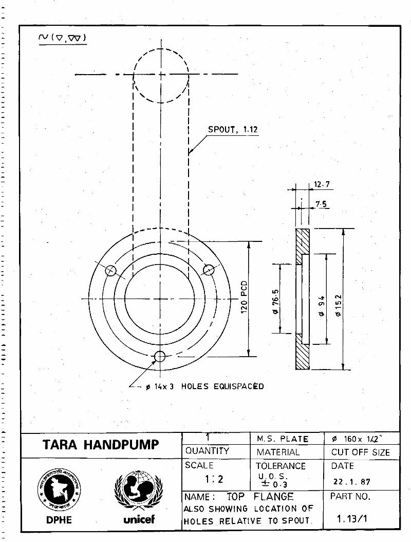
A
SPOUT, 1.12
12-7
, 7
p 14x3 HOLES EQUISPACED
in
TARA HANDPUMP TQUANTITY
M.S. PLATE
MATERIAL
0 160x 1/C2
CUTOFF SIZE
DPHE
SCALE
1:2TOLERANCEU.O. S.± 0 3
NAME: TOP FLANGEALSO SHOWING LOCATION OFHOLES RELATIVE TO SPOUT.
DATE
2 2 . 1 . 87
PART NO.
1.13/1
<t 9 4 . 5
NOTE: MAKE FROM ACRYLONITRILE BUTADIENE RUBBER
BAYER PERBUNAN N3 307 NS OR EQUIVALENT
HARDNESS 5 5 - 7 0 SHORE *A*
TARA HANDPUMP 1QUANTITY
SEE NOTE
MATERIAL
AS MOULDED
CUTOFF SIZE
DPHE
Hiunicef
SCALE
i: 1TOLERANCE
U.O. S± 0 - 5
NAME:
GROMMET
DATE
22. 1. 87
PART NO.
1.14/1

I • < I I I I I \ I I I I I I I ' • I I I . I M I I I I I I ' I I I i M t ' M ' ' I i l I | i f
TARA HANDPUMP PRODUCTION MANUAL
PUMP HEAD
Part No
(withoutamendment)and Name
1.20
Bottom FlangeSub-Assembly
ASSEMBLY
Production ProcessSequence
1 Fix Flange and Lugs inassembly jig
2 Electric arc weld
3 Inspect
4 Hot dip galvanize
5 Inspect
(Approx productiontime 70 minutes}
PRODUCTION INFORMATION
BOTTOM FLANGE
Major Production
Machine Tools /Equipment
1 Electric arc welder
(minimum 180A)
2 Hot dip galvanizingbath
SUB ASSEMBLY
Major ProductionAids
Non-slip assemblywelding jig
-
PAGE B I S
CRITICAL ASPECTSof
Production and Inspection
Check
1 That lugs are welded toflange at 90° and end of lugs
should not interfere withinternal thread
2 Protect threads from
* galvanizing or after galvanizingrun tapping die
3 Surface finish smooth

I I I I I I I I M I ,1 I ) I M M t ' I I I I I I l l I <
TARA HANDPUMf> PRODUCTION MANUAL
PUMPHEAD ASSEMBLY
Part No(withoutamendment}and Name
1.21
Bottom Flange
1.22Stud
Production ProcessSequence
1 Cut blanks from MSplates by oxy acetylene gas
2 Turn
3 Bore
4 Drillholes
5 Tap thread
6 Inspect
1 Turn
2 Form thread
3 Cutoff
4 Zinc electroplate
5 Inspect -
PRODUCTION INFORMATION
BOTTOM FLANGE SUB ASSEMBLY
Major ProductionMachine Tools /Equipment
1 Oxy acetylene gascutting equipment
2 Lathe machine
3 Drilling machine with. reversible tapping
chuck
Lathe machine
Major ProductionAids
1 Circular guide forgas cutting
2 Drill jig
Go not go snap gaugeor Ring gauge forthreaded externaldiameter
PAGE B1-6
CRITICAL ASPECTSof
Production,'and Inspection
Check
Location of 3x0.5" BSW holesequispaced on PCD 120mm
Quality of threads
M M i i I P I I i I ' ' M M M I i I • > I ' I I I i M I 1 > i i I
ITARA HANDPUMP PRODUCTION MANUAL
PUMP HEAD
Part No(withoutamendment)and Name
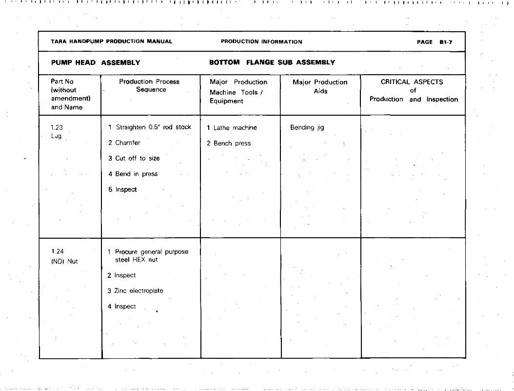
1.23Lug
1.24
(ND) Nut
ASSEMBLY
Production ProcessSequence
1 Straighten 0.5" rod stock
2 Chamfer
3 Cut off to size
4 Bend in press
5 Inspect
1 Procure general purposesteel HEX nut
2 Inspect
3 Zinc electroplate
4 Inspect«
PRODUCTION INFORMATION
BOTTOM FLANGE SUB ASSEMBLY
Major Production
Machine Tools /Equipment
1 Lathe machine
2 Bench press
Major ProductionAids
Bending jig
PAGE B1-7
CRITICAL ASPECTSof
Production and Inspection

SECTION A-A
IT
ELECTRIC ARCFILLET WELD
HOT DIP GALVANISE TO
BS 729 : 1971
PROTECT THREADS
TARA HANDPUMPT
QUANTITY MATERIAL CUT OFF SIZE
SCALE
1: 2TOLEHANCE
NAME:
DPHE unicef
BOTTOM FLANGESUB ASSEMBLY
DATE
22.1 . 87
PART NO.
1-20
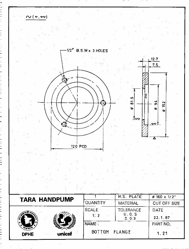
1/2" B.S.Wx 3 HOLES
in
I
12 7
7-5
in
TARA HANDPUMPQUANTITY
M.S. PLATE
MATERIAL
160 x 1/2"
CUTOFF SIZE
SCALE
i : 2
TOLERANCEU. 0. S± 0.3
DPHE unicef
NAME :
BOTTOM FLANGE
DATE
22 .1 .87
PART NO.
1 . 21

CD1/1
15 12
35
NOTE : MAY BE MADE FROM STANDARD BOLT Ml B.S.W.
ELECTRO GALVANISE
TARA HANDPUMPQUANTITY
M.S
MATERIAL CUTOFF SIZESCALE
2 : 1TOLERANCE
U.O. S±0-3
NAME:
DPHE unicef STUD
DATE
2 2 . 1 . 8 7
PART NO.
1 22

oo
2xA5c
62
TARA HANDPUMPQUANTITY
M. S
MATERIAL
1/2''x160
CUT OFF SIZE
DPHE
SCALE TOLERANCEU.O. S .± 0-3
DATE
31. 1. 87
NAME
unicef LUG
PART NO.
1.23
TARA HANDPUMP PRODUCTION MANUAL
PUMPHEAD ASSEMBLY
Part No(withoutamendment}and Name
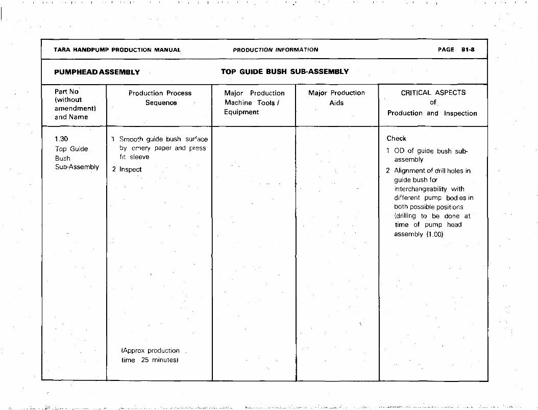
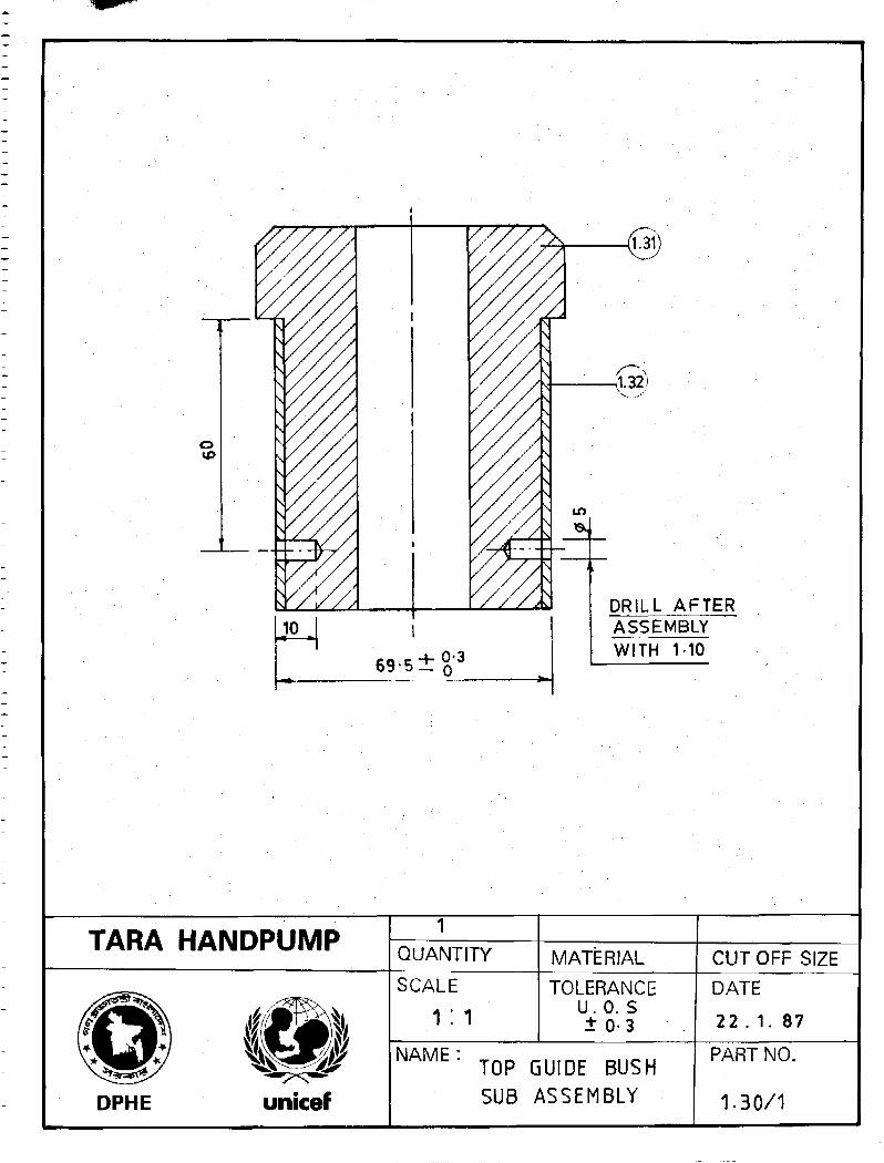
1.30
Top GuideBushSub-Assembly
Production ProcessSequence
1 Smooth guide bush surfaceby emery paper and press
fit sleeve
2 Inspect
(Approx productiontime 25 minutes)
PRODUCTION INFORMATION
TOP GUIDE BUSH SUB-ASSEMBLY
Major ProductionMachine Tools /Equipment
Major Production
Aids
PAGE B1-8
CRITICAL ASPECTSof
Production and Inspection
Check
1 OD of guide bush sub-assembly
2 Alignment of drill holes inguide bush forinterchangeability withdifferent pump bodies inboth possible positions(drilling to be done attime of pump headassembly (1.00)

TARA HANDPUMP PRODUCTION MANUAL
PUMPHEAD ASSEMBLY
Part No(withoutamendment)and Name
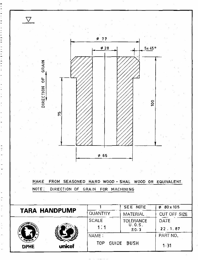
1.31Top GuideBush
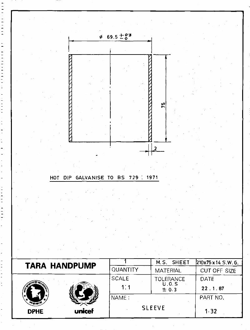
1.32Sleeve
Production ProcessSequence
1 Prepare stock dia80x105mm fromseasoned wood
2 Turn3 Bore4 Face
5 Chamfer
6 Cut off to finish size7 Inspect
1 Shear into strip of MSsheet 210 mm x75 mm x 14 SWG
2 Roll into circular tube3 Seam weld by
Oxy acetylene gas4 Hammer welded joint
5 Reroll6 Hot dip galvanize7 Inspect
PRODUCTION INFORMATION
TOP GUIDE BUSH SUB-ASSEMBLY
Major Production
Machine Tools /Equipment
Wood turning lathe
1 Manual or powershearing machine
2 Bending rollermachine
3 Oxy acetylene gaswelding equipment
Major ProductionAids.
Cylindrical mandrel ofdia 65.5 mm ±0.5(hardened & tempered)
PAGE B1-9
CRITICAL ASPECTSof
Production and Inspection
Check
1 For direction of wood grain
along the direction of hole
2 Quality of wood
Check
1 Outside diameter2 Quality of pipe seam3 Surface finish
TARA HANDPUMPQUANTITY MATERIAL CUT OFF SIZE
SCALE
1:1TOLERANCE
U. 0. S± 0 - 3
NAME:
DPHE unicef
TOP GUIDE BUSHSUB ASSEMBLY
DATE
22 . 1. 87
PART NO.
1.30/1
V
<(X
O
tuDC
77
0 28
0 65
MAKE FROM SEASONED HARD WOOD - SHAL WOOD OR EQUIVALENT.
NOTE: DIRECTION OF GRAIN FOR MACHINING
TARA HANDPUMP QUANTITY
SEE NOTE
MATERIAL
0 80x105
CUT OFF SIZE
DPHE
SCALE
1:1TOLERANCE
U.O.S.±0-3
NAME :
TOP GUIDE BUSH
DATE
22 . 1.87
PART NO.
1 -31
.1
1
,•
1
•
•
fl» 69.5 t g ' 3
/// : • . . '
/
/
/
/
/ • •
/
/
/
/
/
/
/
/
/
/
/
/
/
/
• . ' • • '
/
/
/
*
t
t//
/
//
t
' . /
4/
/
/• ' 4
HOT DIP GALVANISE TO BS 729 : 1<
t •
t
*
t
t
* \£%* t-*t
f
/
f
t
*
t
/ i
.2
J71
TARA HANDPUMP
DPHE unicef
1QUANTITY
SCALE
1:1
M.S. SHEET
MATERIAL
TOLERANCEu.o.s± 0-3
NAME :
SLEEVE
210x75 x US.W.G.
CUT OFF SIZE
DATE
22 . 1. 87
PART NO.
1-32
I I ' I ' > i ' > ' I J i I ' I i I I I ' U ' i I ' > < M I i I i I I > I
TARA HANDPUMP PRODUCTION MANUAL PRODUCTION INFORMATION PAGE B1-10
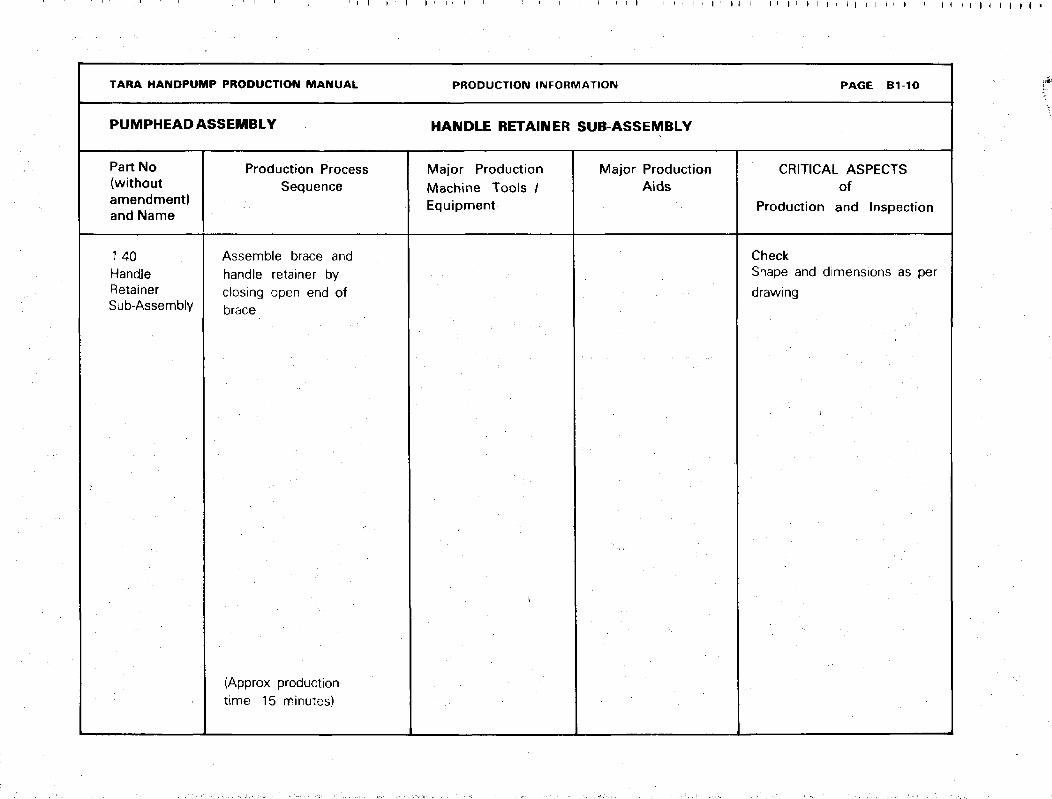
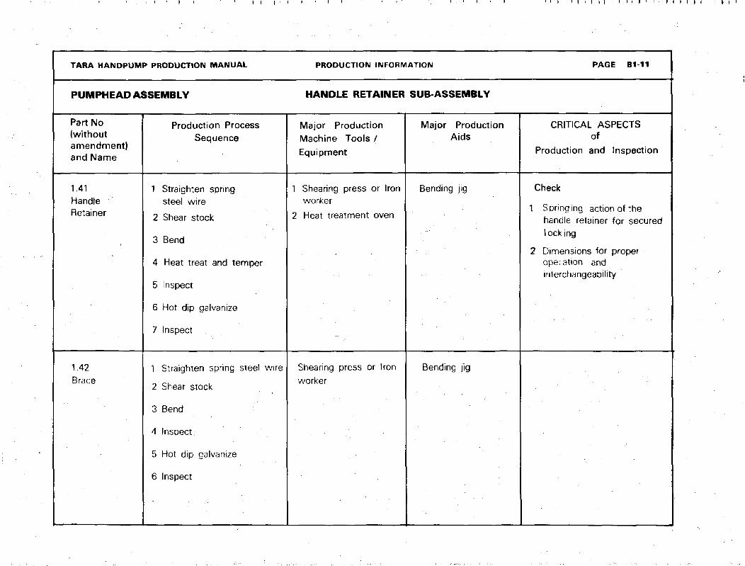
PUMPHEAD ASSEMBLY HANDLE RETAINER SUB-ASSEMBLY
Part No(withoutamendment)and Name
Production ProcessSequence
Major ProductionMachine Tools /Equipment
Major ProductionAids
CRITICAL ASPECTSof
Production and Inspection
1.40HandjeRetainerSub-Assembly
Assemble brace andhandle retainer byclosing open end ofbrace
(Approx productiontime 15 minutes)
CheckShape and dimensions as per
drawing
I I I I ' I ' I I I I I I I I I I I I I I I I I I
TARA HANDPUMP PRODUCTION MANUAL
PUMPHE AD ASSEMBLY
Part No(withoutamendment)and Name
1.41HandleRetainer
1.42Brace
Production ProcessSequence
1 Straighten springsteel wire
2 Shear stock
3 Bend
4 Heat treat and temper
5 Inspect
6 Hot dip galvanize
7 Inspect
1 Straighten spring steel wire
2 Shear stock
3 Bend :
4 Inspect
5 Hot dip galvanize
6 Inspect
PRODUCTION INFORMATION
HANDLE RETAINER SUB-ASSEMBLY
Major ProductionMachine Tools /Equipment
1 Shearing press or Ironworker
2 Heat treatment oven
Shearing press or Iron
worker
Major ProductionAids
Bending jig
Bending jig
PAGE B1-11
CRITICAL ASPECTSof
Production and Inspection
Check
1 Springing actionofthehandle retainer for securedlocking
2 Dimensions for properoperation andinterchangeability
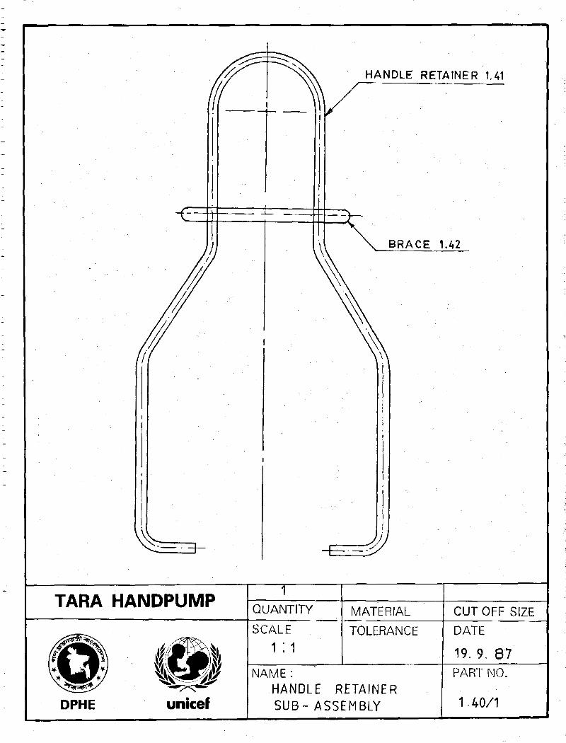
HANDLE RETAINER 1.41
BRACE 1.42
TARA HANDPUMP TQUANTITY MATERIAL CUTOFF SIZE
DPHEw
unicef
SCALE
1:1TOLERANCE
NAME:HANDLE RETAINERSUB- ASSEMBLY
DATE
19. 9. 87PART NO.
1 • 40/1

NOTE;
MAKE FROM HARD DRAWNSPRING
HARDEN
aUENCH
TEMPER
STEEL,
AT 840°C,
IN WATER
400°C,
ALL UNSPECIFIED
RADU-5 , HOT DIP
GALVANISE
20
TARA HANDPUMP i
QUANTITY MATERIAL
0 3/16'x500
CUTOFF SIZESCALE
1 : 1TOLERANCE
NAME:
DPHE unicef HANDLE RETAINER
DATE
19. 9. 87
PART NO.
1.41/1
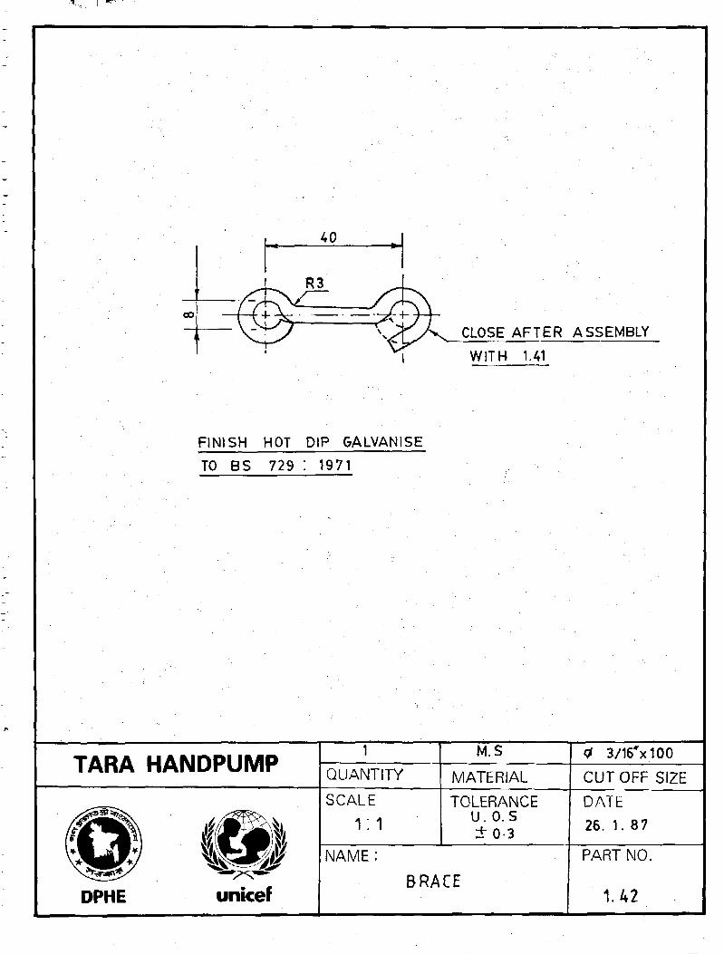
FINISH HOT DIP GALVANISE
TO BS 729 : 1971
CLOSE AFTER ASSEMBLY
WITH 1.41
TARA HANDPUMP1
QUANTITY
M.S
MATERIAL
<f 3/16*x100
CUT OFF SIZE
DPHE
SCALE
1:1TOLERANCE
U.O. S+ 03
NAME :
BRACE
DATE
26. 1. 87
PART NO.
1.42
TARA HANDPUMP PRODUCTION MANUAL PAGE B2 0
HANDLE ASSEMBLY
PRODUCTION INFORMATION
DRAWINGS
•
TARA HANDPUMP PRODUCTION MANUAL PRODUCTION INFORMATION PAGE B2-1 / 1
HANDLE ASSEMBLY
Part No(withoutamendment)and Name
Production ProcessSequence
Major ProductionMachine Tools /Equipment
Major ProductionAids
CRITICAL ASPECTSof
Production and Inspection
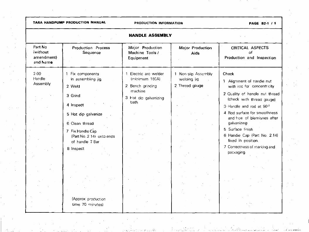
2.00HandleAssembly
1 Fix componentsin assembling jig
2 Weld
3 Grind
4 Inspect
5 Hot dip galvanize
6 Clean thread
7 Fix Handle Cap(Part No. 2.14) onto endsof handle T-Bar
8 Inspect
(Approx productiontime 70 minutes)
1 Electric arc welder(minimum 180A)
2 Bench grindingmachine
3 Hot dip galvanizingbath
1 Non-slip Assemblywelding jig
2 Thread gauge
Check
1 Alignment of handle nutwith rod for concentricity
2 Quality of handle nut thread(check with thread gauge}
3-Handle and rod at 90°
4 Rod surface for smoothnessand free of blemishes aftergalvanizing
5 Surface finish
6 Handle Cap (Part No. 2.14)fixed in position.
7 Correctness of marking andpackaging

TARA HANDPUMP PRODUCTION MANUAL PRODUCTION INFORMATION PAGE B2-2
HANDLE ASSEMBLY
Part No
(Withoutamendment)and Name
2.11Rod
2.12Handle
Production ProcessSequence
1 Saw2 Mill end profile
3 rile4 Inspect
1 Saw \,2 File3 Inspect
Major ProductionMachine Tools/Equipment
1 Reciprocating sawmachine
Band machineor
Circular sawmachine
2 milling machine
Reciprocating sawmachine
orBand saw machine
orCircular sawmachine
Major ProductionAids
1 Sawing jig2 Milling fixture
Sawing jig :
CRITICAL ASPECTSof
Production and Inspection
Check
1. Pipe straightness after sawing2. End profile after milling to
conform to drawing forease of welding
. •
Check
Pipe straightness and finishingof ends after sawing.

TARA HANDPUMP PRODUCTION MANUAL PRODUCTION INFORMATION PAGE B2-3/1
HANDLE ASSEMBLY
Part No(Withoutamendment)and Name
2.13Handle Nut
2.14HandleCap
Production ProcessSequence
1 Turn2 Form groove
o race4 Bore5 Form thread6 Chamfer7 Cut off from stock8 Inspect9 Mill or shave flat surface
10 Inspect
1 Injection mould usingany common durableplastic resin
2 Inspect
Major ProductionMachine Tools/Equipment
1 Lathe machine
2 Milling machine
1 Injection mouldingmachine
2 Die mould
Major- ProductionAids
1 Go, not go threadplug gauge
2 Ring gauge
orSnap gauge
CRITICAL ASPECTSof
Production and Inspection
Check
1 Dimension 22 mm after milling2 Length formation and fit of
internal thread to conform toStandard, using a thread gauge
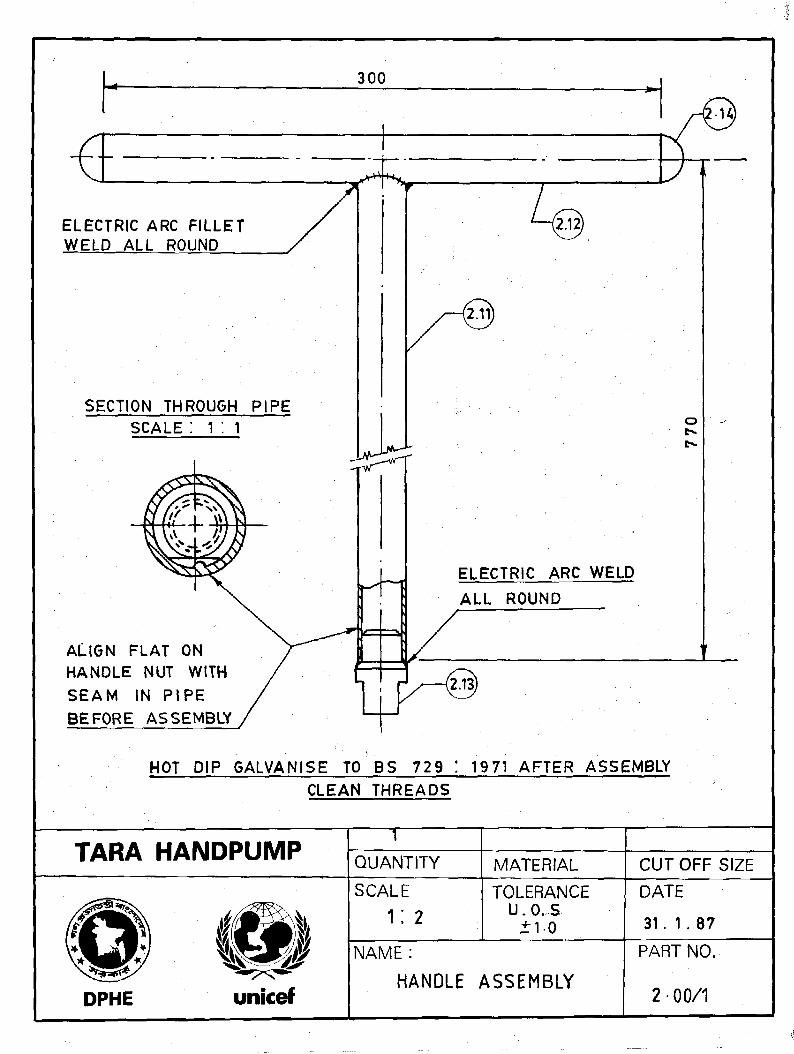
300
ELECTRIC ARC FILLETWELD ALL ROUND
SECTION THROUGH PIPE
ALIGN FLAT ONHANDLE NUT WITHSEAM IN PIPEBEFORE ASSEMBLY
ELECTRIC ARC WELD
ALL ROUND
HOT DIP GALVANISE TO BS 729 ! 1971 AFTER ASSEMBLY
CLEAN THREADS
TARA HANDPUMPT
QUANTITY MATERIAL CUT OFF SIZE
DPHE
SCALE
1 : 2TOLERANCE
U. 0. S+ 10
NAME :
HANDLE ASSEMBLY
DATE
31. 1 . 87
PART NO.
2-00/1
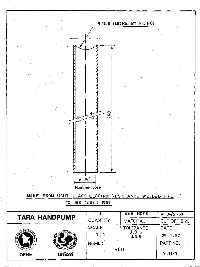
R 13.5 (MITRE BY FILING)
0 3/4*
Nominal bore
MAKE FROM LIGHT BLACK ELECTRIC RESISTANCE WELDED PIPE
TO BS 1387 ; 1967
TARA HANDPUMP1
QUANTITY
SEE NOTE
MATERIAL
3/4*x760
CUTOFF SIZE
SCALE
iTOLERANCE
U.O.S± 0 5
DATE
25 . 1.87
NAME:
unicefROD
PART NO.
2 -11/1

300
LU
om
O
REMOVE SHARP CORNERS
MAKE FROM LIGHT BLACK ELECTRIC RESISTANCE
WELDED PIPE TO BS 1387 : 1967
TARA HANDPUMPQUANTITY
SEE NOTE
MATERIAL
3/4x300
CUT OFF SIZE
SCALE
1:1TOLERANCE
U.O.S *+ 0-5
NAME :
DPHE unicefHANDLE
DATE
24. 11. 87
PART NO.
2-12/1

w
CM
50
30
20
2x45°
o+ 1
" fN
30
TARA HANDPUMP QUANTITYM.S.
MATERIAL
0 1V4*X 5 2
CUT OFF SIZE
DPHE unicef
SCALE
1 ; 1TOLERANCE
U.O.St 0-2
NAME :
HANDLE NUT
DATE
31. 1 . 87
PART NO.
2-13
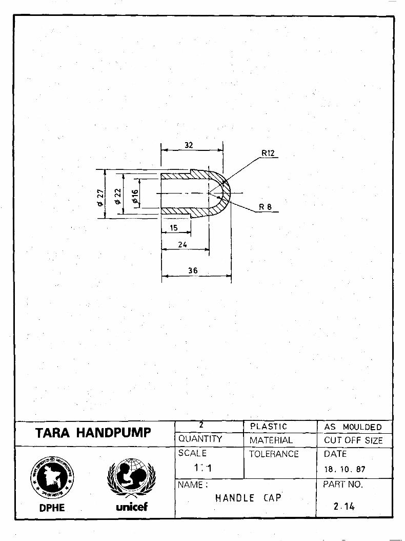
R12
TARA HANDPUMPT
QUANTITY
PLASTIC
MATERIAL
AS MOULDED
CUTOFF SIZE
SCALE TOLERANCE
DPHE
NAME :
HANDLE CAP
DATE
18. 10. 87
PART NO.
2 1 4

TARA HANDPUMP PRODUCTION MANUAL PAGE B3-0
PUMP ROD ASSEMBLY
WITH
TOP CONNECTOR
PRODUCTION INFORMATION
DRAWINGS
TARA HANDPUMP PRODUCTION MANUAL PRODUCTION INFORMATION PAGE B3- 1 / I
PUMP ROD ASSEMBLY WITH TOP CONNECTOR
Part No
(Withoutamendment)and Name
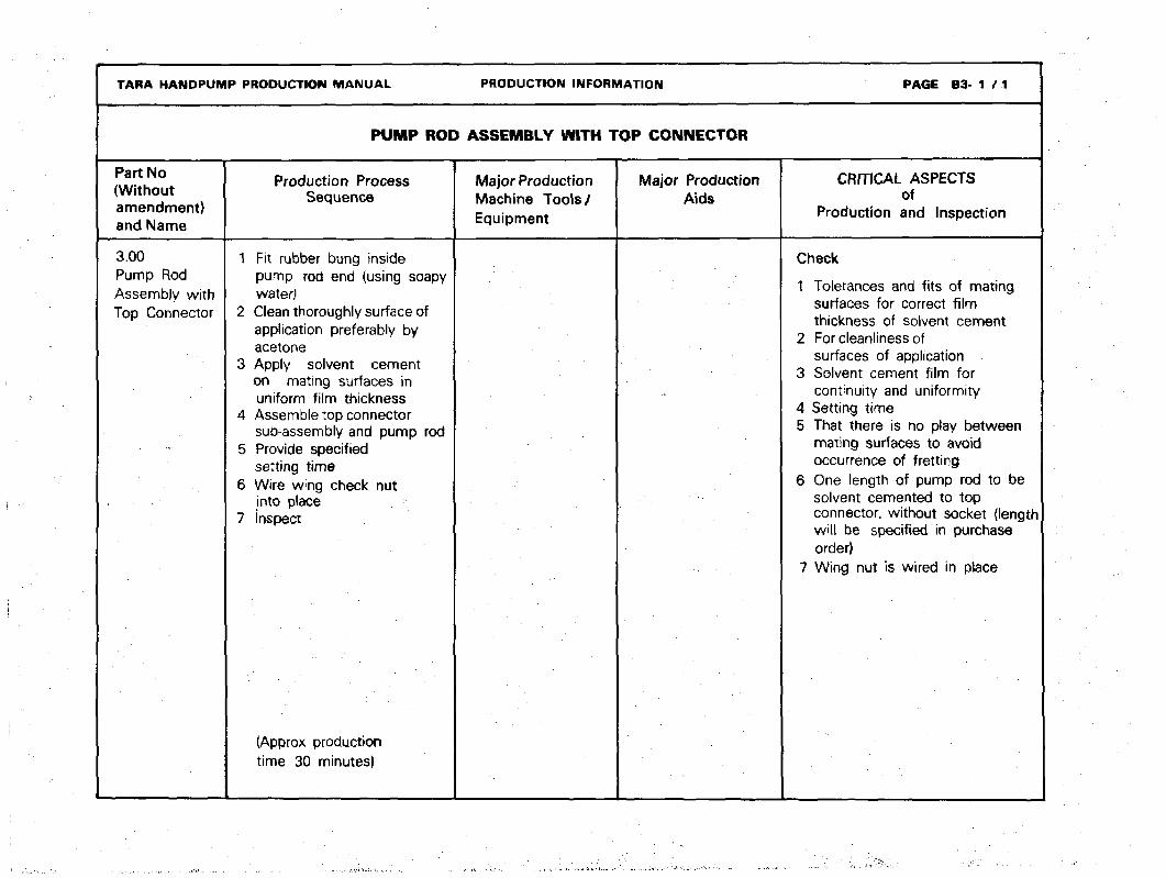
3.00Pump RodAssembly withTop Connector
Production ProcessSequence
1 Fit rubber bung insidepump rod end (using soapywater!
2 Clean thoroughly surface ofapplication preferably by
acetone3 Apply solvent cement
on mating surfaces inuniform film thickness
4 Assemble top connectorsub-assembly and pump rod
5 Provide specifiedsetting time
6 Wire wing check nutinto place
7 inspect
(Approx productiontime 30 minutes)
Major ProductionMachine Tools/Equipment
Major ProductionAids
CRITICAL ASPECTSof
Production and Inspection
Check
1 Tolerances and fits of matingsurfaces for correct filmthickness of solvent cement
2 For cleanliness ofsurfaces of application
3 Solvent cement film forcontinuity and uniformity
4 Setting time5 That there is no play between
mating surfaces to avoidoccurrence of fretting
6 One length of pump rod to besolvent cemented to topconnector, without socket (lengthwill be specified in purchaseorder)
7 Wing nut is wired in place

WING CHECK NUT
TOP CONNECTOR SUB ASSEMBLY, 3. 10
PUMP ROD SUB ASSEMBLY, 3.20
0 \V£ CLASSED" P.V. C PIPE
PUMP ROD BUNG. 3. 22
NOTE :
ALL JOINTS SOLVENT CEMENTED
PISTON ASSEMBLY WITH
BOTTOM CONNECTOR
TARA HANDPUMPQUANTITY MATERIAL CUTOFF SIZE
SCALE
1 : 5
TOLERANCE DATE
2 .2 . 87
DPHE unicef
NAME:
PUMP ROD ASSEMBLY WITH
TOP CONNECTOR
PART NO.
3-00/1

TARA HANDPUMF> PRODUCTION MANUAL
PUMP ROD ASSEMBLY Q
WITH TOP CONNECTOR
Part No(Withoutamendment)and Name
3.10Top ConnectorSub-Assembly
Production ProcessSequence
1 Assemble all the parts i.e.bush, bolt, washers, nut andwing check nut in relativepositions
2 Use solvent cement whilefitting bolt into uPVC
bush as filler3 Tighten nut and punch to
lock the nut with rod4 Inspect
(Approx productiontime 25 minutes)
PRODUCTION INFORMATION
CONNECTOR SUB-ASSEMBLY
Major ProductionMachine Tools/Equipment
Major ProductionAids
PAGE B3-2 / 1
CRITICAL ASPECTSof
Production and Inspection
Check
1 Locking of nut with bolt2 Whether solvent cement has
been used while fitting boltinto bush
3 Surface finish4 OD of bush to match ID
of pump rod
TARA HANDPUMP PRODUCTION MANUAL PRODUCTION INFORMATION P f l G E B3-3
r i c S TOP CONNECTOR SUB-ASSEMBLY
Part No(Withoutamendment}and Name
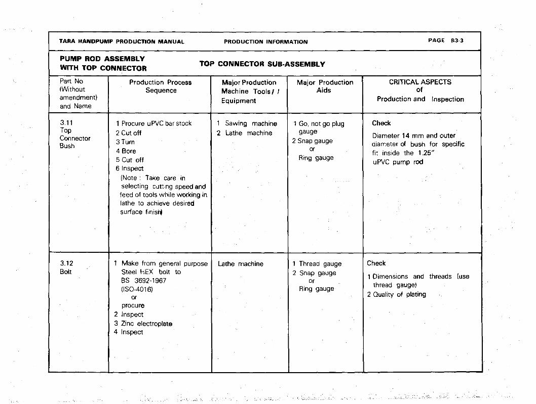
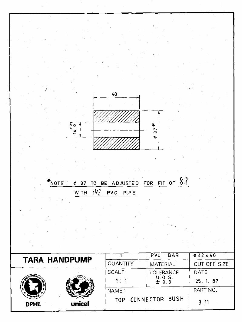
3.11TopConnectorBush
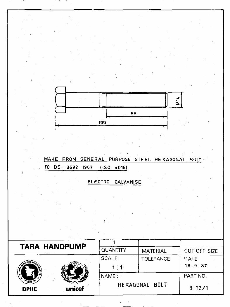
3.12Bolt
Production ProcessSequence
1 Procure uPVC bar stock2 Cut off3 Turn4 Bore5 Cut off6 Inspect
(Note : Take care inselecting cutting speed andfeed of tools while working inlathe to achieve desiredsurface finish)
1 Make from general purposeSteel HEX bolt toBS 3692-1967(ISO-4016)
orprocure
2 Inspect3 Zinc electroplate4 Inspect
Major ProductionMachine Tools/ /Equipment
1 Sawing machine2 Lathe machine
Lathe machine
Major ProductionAids
1 Go, not go pluggauge
2 Snap gaugeor
Ring gauge
1 Thread gauge2 Snap gauge
orRing gauge
CRITICAL ASPECTSof
Production and Inspection
Check
Diameter 14 mm and outerdiameter of bush for specificfit inside the 1.25"uPVC pump rod
Check
1 Dimensions and threads (usethread gauge)
2 Quality of plating
TARA HANDPUMP PRODUCTION MANUAL
PUMP ROD ASSEMBLYWITH TOP CONNECTOR
Part Noand Name
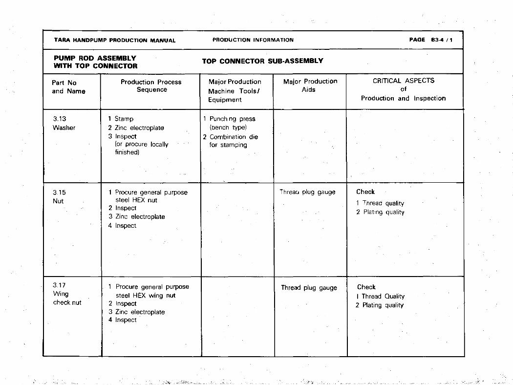
3.13Washer
3.15Nut
3.17Wingcheck nut
Production ProcessSequence
1 Stamp2 Zinc electroplate3 Inspect
(or procure locallyfinished)
1 Procure general purposesteel HEX nut
2 Inspect3 Zinc electroplate4 Inspect
1 Procure general purposesteel HEX wing nut
2 Inspect3 Zinc electroplate4 Inspect
PRODUCTION INFORMATION
TOP CONNECTOR SUB-ASSEMBLY
Major ProductionMachine Tools/Equipment
1 Punching press(bench type}
2 Combination diefor stamping
Major ProductionAids
Thread plug gauge
Thread plug gauge
PAGE B3 4 / 1
CRITICAL ASPECTSof
Production and Inspection
Check
1 Thread quality2 Plating quality
CheckI Thread Quality2 Plating quality
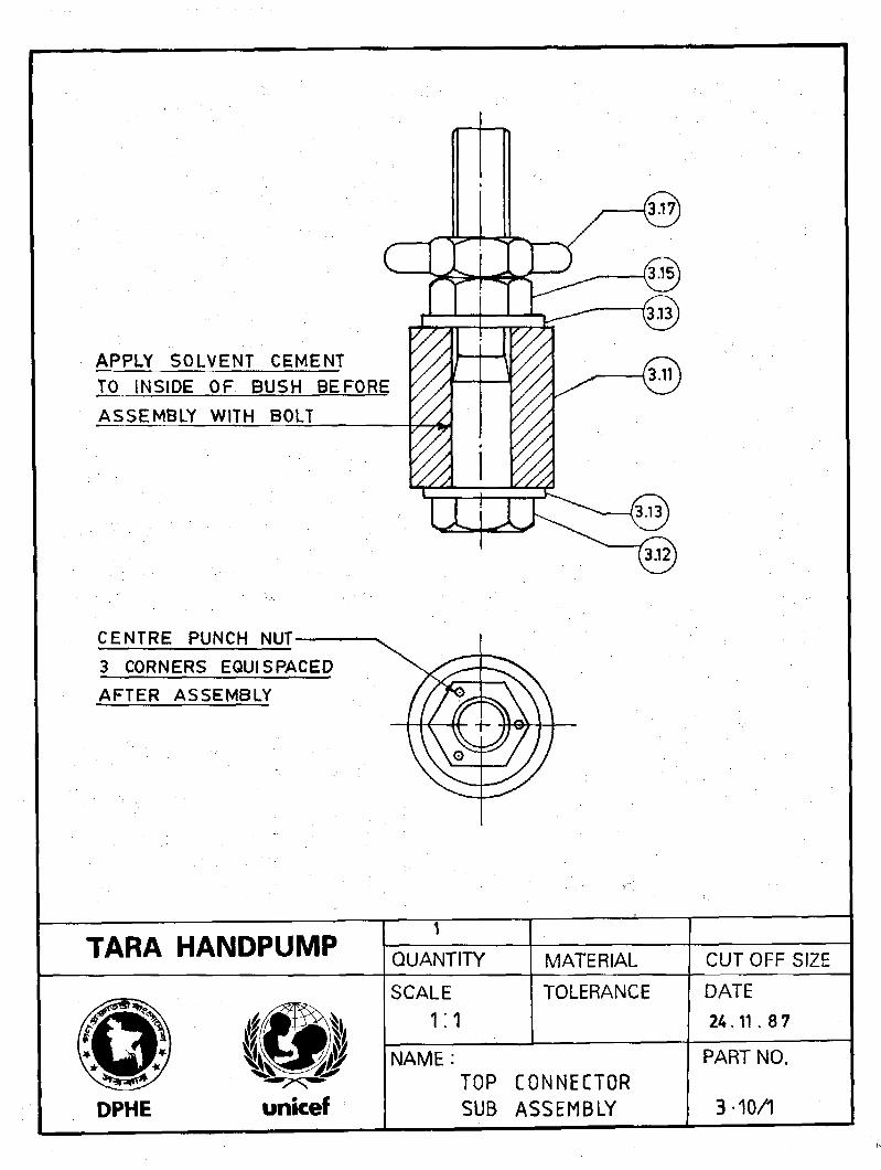
APPLY SOLVENT CEMENT
TO INSIDE OF BUSH BEFORE
ASSEMBLY WITH BOLT
CENTRE PUNCH NUT-
3 CORNERS EQUISPACED
AFTER ASSEMBLY
TARA HANDPUMP QUANTITY MATERIAL CUT OFF SIZE
SCALE
1:1TOLERANCE
NAME:
DPHE unicefTOP CONNECTORSUB ASSEMBLY
DATE
24.11. 8 7
PART NO.
3-10/1
bo+
en
* 0-3NOTE i 0 37 TO BE ADJUSTED FOR FIT OF 0-1
WITH 11/2" PVC PIPE
TARA HANDPUMPQUANTITY
PVC BAR
MATERIAL
0 42 x 40
CUT OFF SIZE
SCALE
1 ; 1TOLERANCE
U.O. S.± 0.3
DPHE unicef
NAME :
TOP CONNECTOR BUSH
DATE
25. 1. 87
PART NO.
3.11
r
\
100
55
MAKE FROM GENERAL PURPOSE STEEL HEXAGONAL BOLT
TO B S - 3 6 9 2 - 1 9 6 7 (ISO 4016)
ELECTRO GALVANISE
TARA HANDPUMPQUANTITY MATERIAL CUTOFF SIZE
SCALE
1:1TOLERANCE
NAME:
DPHE unicefHEXAGONAL BOLT
DATE
18.9 . 87
PART NO.
3-12/1

STAMP FROM 1/8 MS SHEET
FINISH ELECTRO GALVANISE
TARA HANDPUMP
DPHE unicef
QUANTITY
SCALE
NAME:
M.S.MATERIAL
TOLERANCEU. 0. Si : o-3
WASHER
CUT OFF SIZE
DATE
22. 1. 87
PART NO.
3-13

JAM
nmnELECTRO GALVANISE
TARA HANDPUMP 1QUANTITY MATERIAL CUT OFF SIZE
DPHE
SCALE
1; 1TOLERANCE DATE
22 . 1 . 87
NAME:
NUTPART NO.
3-15

ELECTRO- GALVANISE
TARA HANDPUMP 1QUANTITY MATERIAL CUT OFF SIZE
SCALE
1:1TOLERANCE DATE
18. 9. 87
NAME :
DPHE unicef WING CHECK NUT
PART NO.
3.17
TARA HANDPUMP PRODUCTION MANUAL PRODUCTION INFORMATION PAGE B3 6
PUMP ROD ASSEMBLYWITH TOP CONNECTOR PUMP ROD SUB ASSEMBLY
Part Noand Name
Production ProcessSequence
Major ProductionMachine Tools/Equipment
Major ProductionAids
CRITICAL ASPECTSof
Production and Inspection
3.20 (ND)Pump rodSub-Assembly

TARA HANDPUMP PRODUCTION MANUAL PRODUCTION INFORMATION PAGE B3-7 / 1
PUMP ROD ASSEMBLY p U M p R 0 D SUB ASSEMBLYWITH TOP CONNECTOR
Part No(Withoutamendment)and Name
3.21 (ND)Pump rod
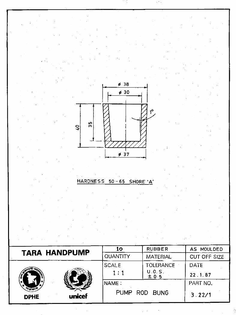
3.22 Pumprod Bung
Production ProcessSequence
1 Inspect2 Saw to size3 Inspect
1 Compound and rollrubber doughinto sheets
2 Mould and vulcanize
3 Inspect
Major ProductionMachine Tools/Equipment
Sawing machine
1 Mixing roller2 Press machine3 Die mould
Major ProductionAids
Sawing jig
CRITICAL ASPECTSof
Production and Inspection
Check
1 That only UNICEF quality assuredpipes to BS 3505 are used
2 Alignment, concentricity anddimensions of sockets
Check
1 Hardness 50-65 shore "A"2 Rubber quality (visual check)
in
38
30
37
HARDNESS 50 - 65 SHORE l A'
TARA HANDPUMP loQUANTITY
RUBBERMATERIAL
AS MOULDED
CUTOFF SIZE
SCALE
l : 1TOLERANCEU.O.S.± 0 5
DPHE unicef
NAME:
PUMP ROD BUNG
DATE
22. 1.87
PART NO.
3 .22 /1
TARA HANDPUMP PRODUCTION MANUAL PAGE B4-0
•
•
PISTON ASSEMBLY
WITH
BOTTOM CONNECTOR
PRODUCTION INFORMATION
DRAWINGS
TARA HANDPUMP PRODUCTION MANUAL PRODUCTION INFORMATION PAGE B4-1 / 1
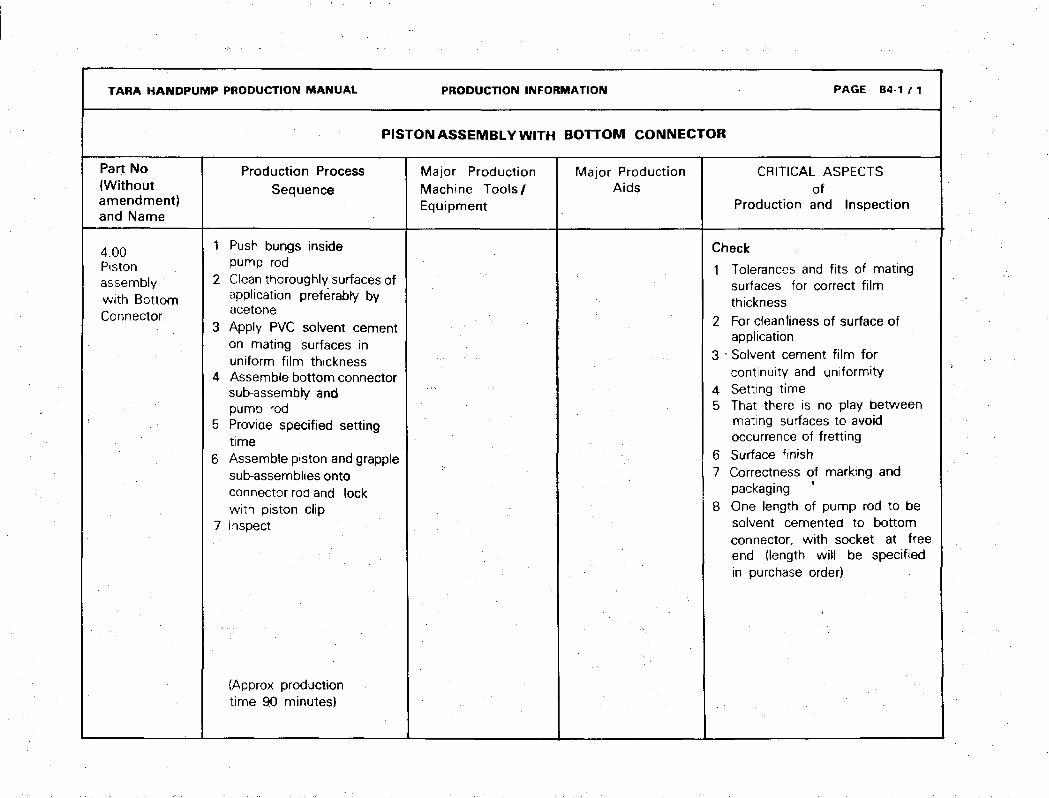
Part No(Withoutamendment)and Name
4.00Pistonassemblywith BottomConnector.
i
PISTON ASSEMBLY WITH
Production ProcessSequence
1 Push bungs insidepump rod
2 Clean thoroughly surfaces ofapplication preferably byacetone
3 Apply PVC solvent cementon mating surfaces inuniform film thickness
4 Assemble bottom connectorsub-assembly andpump rod
5 Provide specified settingtime
6 Assemble piston and grapplesub-assemblies ontoconnector rod and lockwith piston clip
7 Inspect
(Approx productiontime 90 minutes)
Major ProductionMachine Tools/Equipment
BOTTOM CONNECTOR
Major ProductionAids
CRITICAL ASPECTSof
Production and Inspection
Check
1 Tolerances and fits of matingsurfaces for correct filmthickness
2 For cleanliness of surface ofapplication
3 • Solvent cement film forcontinuity and uniformity
4 Setting time5 That there is no play between
mating surfaces to avoidoccurrence of fretting
6 Surface finish7 Correctness of marking and
packaging8 One length of pump rod to be
solvent cemented to bottomconnector, with socket at freeend (length will be specifiedin purchase order)

PUMP ROD BUNG
GLUE WITH SOLVENTCEMENT
0-1/4 PVC PIPE
TARA HANDPUMPQUANTITY MATERIAL CUTOFF SIZESCALE TOLERANCE DATE
31. 1. 87
DPHE unicef
NAME: PISTON ASSEMBLYWITH BOTTOMCONNECTOR.
PART NO.
4-00/1

TARA HANDPUMP PRODUCTION MANUAL PRODUCTION INFORMATION PAGE B4-2
ESS£!£S£mc«m BOTTOM C O«"E C T O R ^ASSEMBLY
Part Noand Name
4.10BottomConnectorSub-Assembly
Production ProcessSequence
1 Assemble all the parts i.e.bush, washers, nut andconnector rod in relativepositions
2 Use solvent cement whilefitting connector rod intouPVC bush as filler
3 Tighten nut and punch tolock the nut with rod
4 Inspect
(Approx productiontime 30 minutes)
Major ProductionMachine Tools/
Equipment
. ••• :
Major Production
AidsCRITICAL ASPECTS
ofProduction and Inspecton
Check
1 Locking of nut withconnector rod
2 Whether solvent cement hasbeen used while fittingconnector rod into bush
3 Surface finish
• •

TARA HANDPUMP PRODUCTION MANUAL PRODUCTION INFORMATION PAGE B4-3
BOTTOM CONNECTOR SUB-ASSEMBLY
Part No(Withoutamendment)and Name
Production ProcessSequence
Major ProductionMachine Tools/Equipment
Major ProductionAids
CRITICAL ASPECTS
of
Production and Inspection
4.11BottomConnectorBush
1 Procure uPVC bar stock2 Cut off3 Turn4 Bore5 Cut off \6 Inspect
(Note : Take care inselecting cutting speedand feed of tools whileworking in lathe to achievedesired surface finish)
1 Sawing machine2 lathe machine
1 Go, not go pluggauge
2 Snap gauge orring gauge
Check
Diameter 12.7 mm and outerdiameter of bush for specificfit inside the 1.25" uPVCpump rod
4.12ConnectorRod
1 Turn different diameters
2 Form groove
3 Form thread
4 Chamfer
5 Cut off
6 Drill
7 Inspect
8 Zinc electroplate
9 Inspect
1 Lathe machine
2 Drilling machine
1 Ring gauge
2 Dial gaugeindicator
3 Thread gauge
Check
1. Dimension 36 mm for tolerance
2. Concentricity of sections ofdifferent diameters.
3. Thread formation and fit
4. Check smooth corner of shoulder
adjacent to flap valve as indicatedin drawing.

TARA HANDPUMP PRODUCTION MANUAL PRODUCTION INr-u.?MATION PAGE B4-4
W'THBOTTOMCONNECTOR BOTTOM CONNECTOR SUB-ASSEMBLY
Part Noand Name
4.13Nut
4.14
Washer
Production ProcessSequence
1 Procure generalpurpose HEX nut
2 Inspect3 Zinc electroplate4 Inspect
1 Stamp2 Zinc electroplate3 Inspect
(or procure locallyfinished)
Major ProductionMachine Tools/Equipment
1 Punching Press(bench type)
2 Combination diefor stamping
Major ProductionAids
CRITICAL ASPECTSniOT
Production and Inspection
NB. Same as part number3.13
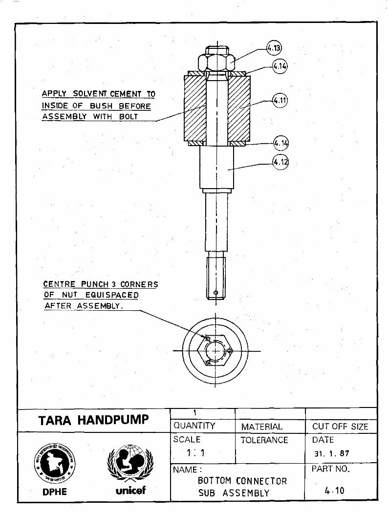
APPLY SOLVENT CEMENT TO
INSIDE OF BUSH BEFORE
ASSEMBLY WITH BOLT
CENTRE PUNCH 3 CORNERSOF NUT EQU1SPACEDAFTER ASSEMBLY.
TARA HANDPUMP1
QUANTITY MATERIAL CUTOFF SIZE
SCALE
1: 1TOLERANCE
DPHE unicef
NAME:
BOTTOM CONNECTORSUB ASSEMBLY
DATE
31. 1. 87
PART NO.
4-10
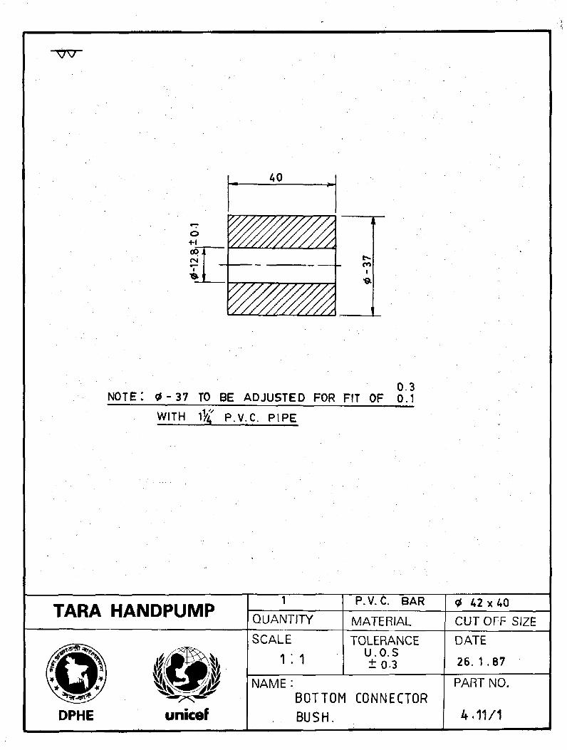
0.3NOTE: 0 - 3 7 TO BE ADJUSTED FOR FIT OF 0,1
WITH p.y.C. PIPE
TARA HANDPUMP QUANTITYP.V. C. BAR
MATERIAL42 x 40
CUTOFF SIZE
DPHE
SCALE
1:1TOLERANCE
U.O.S±0 -3
DATE
26. 1 .87
NAME:BOTTOM CONNECTORBUSH.
PART NO.
4.11/1
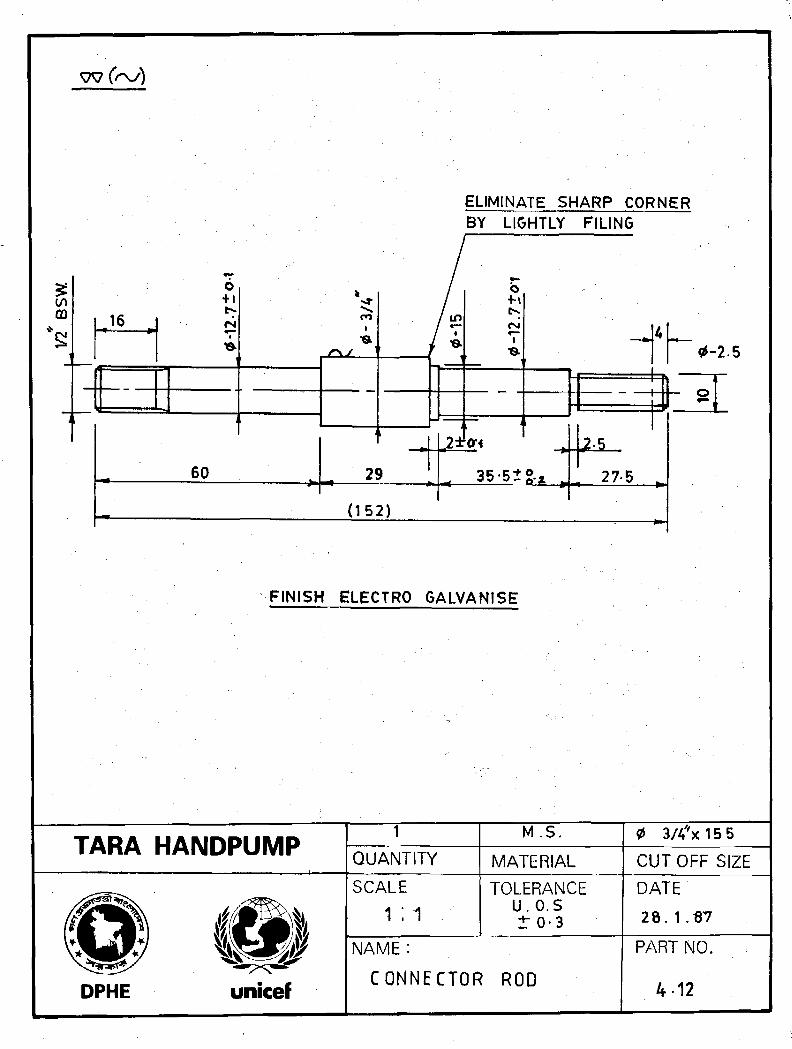
ELIMINATE SHARP CORNERBY LIGHTLY FILING
FINISH ELECTRO GALVANISE
TARA HANDPUMPQUANTITY
M.S.
MATERIAL
0 3/4*x15
CUTOFF SIZE
SCALE
1 :1TOLERANCE
u. o.st 0-3
DPHE unicef
NAME :
CONNECTOR ROD
DATE
28.1.S7
PART NO.
4 12

-B3W-*—
nmn
ELECTRO GALVANISE
TARA HANDPUMPT
QUANTITY MATERIAL CUTOFF SIZE
DPHE
SCALE TOLERANCE DATE26 . 1 . 87
NAME :
NUTPART NO.
4.13
TARA HANDPUMP PRODUCTION MANUAL PRODUCTION INFORMATION PAGE B4-5
PISTON ASSEMBLY WITH
BOTTOM CONNECTORPISTON SUB-ASSEMBLY
Part No(Withoutamendment)and Name
Production ProcessSequence
Major ProductionMachine Tools/Equipment
Major Production
Aids
CRITICAL ASPECTSof
Production and Inspection
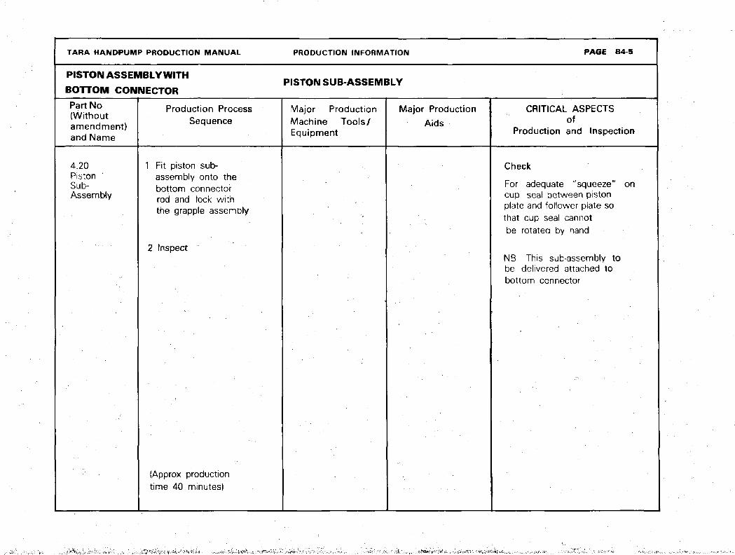
4.20Piston 'Sub-Assembly
Fit piston sub-assembly onto thebottom connectorrod and lock withthe grapple assembly
2 Inspect
Check
For adequate "squeeze" oncup seal between pistonplate and follower plate sothat cup seal cannotbe rotated by hand
NB. This sub-assembly tobe delivered attached tobottom connector
{Approx productiontime 40 minutes)
,.;rf,^:*:--V,:.^;>l

TARA HANDPUMP PRODUCTION MANUAL PRODUCTION INFORMATION PAGE B4-6
PISTION ASSEMBLY PISTON SUB ASSEMBLYWITH BOTTOM CONNECTOR PISTON SUB-ASSEMBLY
Part Noand Name
4.21Flap Valve(Piston)
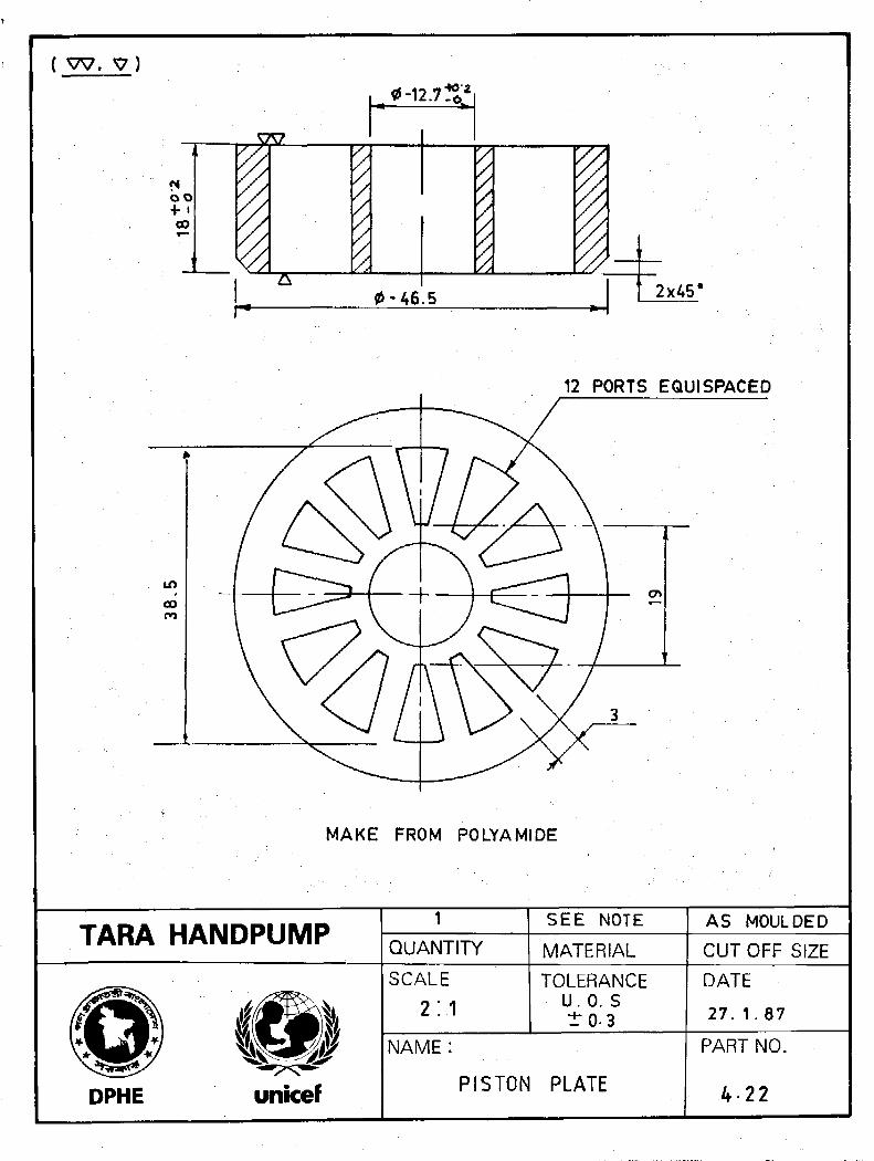
4.22Piston Plate
Production processSequence
1 Blank and pierce2 Inspect
1 Injection mouldusing polyamide resin
2 Face and chamfer3 Inspect
Major ProductionMachine Tools/Equipment
1 Press machine(bench type)
2 Combination die
Injectionmoulding machine
Major ProductionAids
CRITICAL ASPECTSof
Production and Fnspection
Check
1 Elasticity-to return to flatposition briskly after deflection
2 Surface smoothness onsealing side
3 Thickness*4 Outside diameter*5 Inside diameter*
*all dimensions critical
Check
1 Outside diameter*2 Inside diameter*3 Height*4 Sealing surface finish
•all dimensions critical
TARA HANDPUMP PRODUCTION MANUAL PRODUCTION INFORMATION PAGE B4-7
PISTON ASSEMBLY WITH PISTON SUB-ASSEMBLYBOTTOM CONNECTOR
Part Noand Name
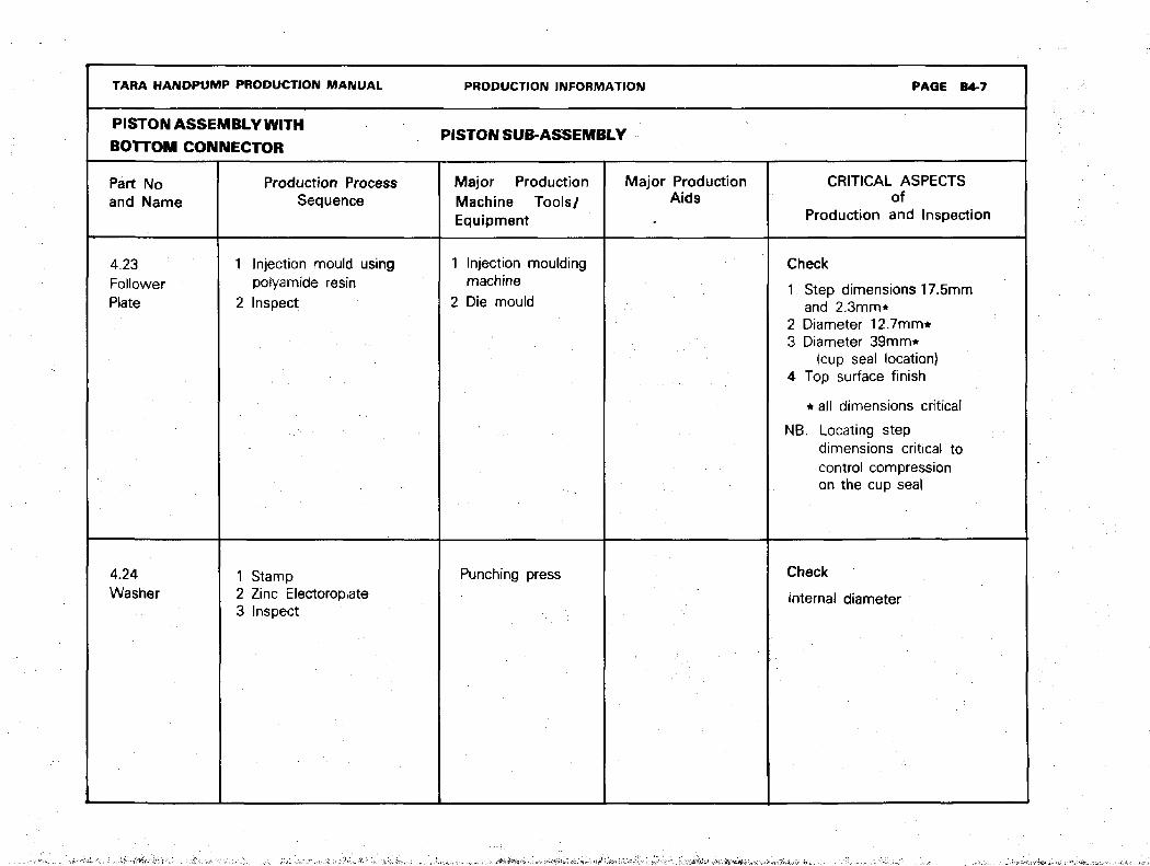
4.23FollowerPlate
4.24Washer
Production ProcessSequence
1 Injection mould usingpoiyamide resin
2 Inspect
1 Stamp2 Zinc Electoroplate3 Inspect
Major ProductionMachine Tools/Equipment
1 Injection mouldingmachine
2 Die mould
Punching press
Major ProductionAids
CRITICAL ASPECTSof
Production and Inspection
Check
1 Step dimensions 17.5mmand 2.3mm*
2 Diameter 12.7mm*3 Diameter 39mm*
(cup seal location)4 Top surface finish
* all dimensions critical
NB. Locating stepdimensions critical tocontrol compressionon the cup seal
Check
internal diameter
TARA HANDPUMP PRODUCTION MANUAL PRODUCTION INFORMATION
PISTON ASSEMBLY
WITH BOTTOM
Part No(Withoutamendment)and Name
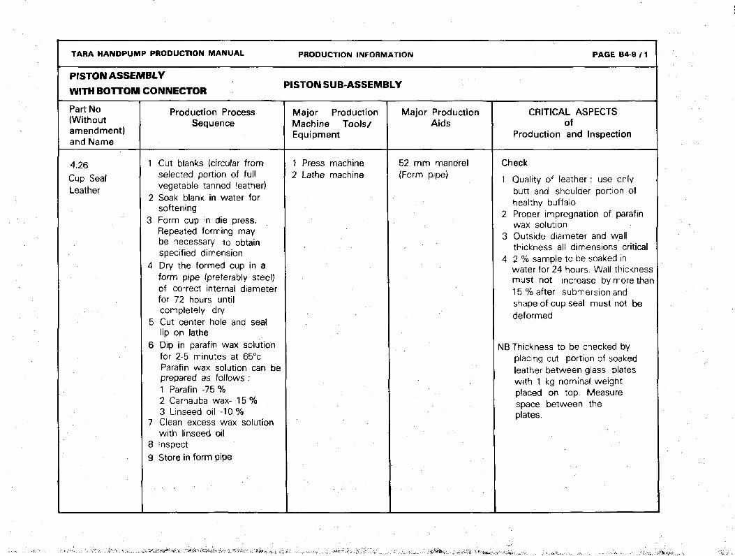
4.26Cup SealLeather
CONNECTOR PISTON SUB-ASSEMBLY
Production ProcessSequence
1 Cut blanks (circular fromselected portion of fullvegetable tanned leather)
2 Soak blank in water forsoftening
3 Form cup in die press.Repeated forming maybe necessary to obtainspecified dimension
4 Dry the formed cup in aform pipe (preferably steel)of correct internal diameterfor 72 hours untilcompletely dry
5 Cut center hole and seallip on lathe
6 Dip in parafin wax solutionfor 2-5 minutes at 65°cParafin wax solution can beprepared as follows :1 Parafin -75 %2 Carnauba wax- 15%3 Linseed oil -10%
7 Clean excess wax solutionwith linseed oil
8 Inspect9 Store in form pipe :
Major ProductionMachine Tools/Equipment
1 Press machine2 Lathe machine
Major ProductionAids
52 mm mandrel(Form pipe)
PAGE B4-9 / 1
CRITICAL ASPECTSof
Production and Inspection
Check
1 Quality of leather : use onlybutt and shoulder portion ofhealthy buffalo
2 Proper impregnation of parafinwax solution
3 Outside diameter and wallthickness all dimensions critical
4 2 % sample to be soaked inwater for 24 hours. Wall thicknessmust not increase by more than15 % after submersion andshape of cup seal must not bedeformed
NB Thickness to be checked byplacing cut portion of soakedleather between glass plateswith 1 kg nominal weightplaced on top. Measurespace between theplates.
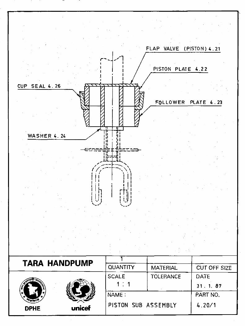
CUP SEAL 4 . 26
WASHER 4. 24
-nr-irr
1 i i
rW.\I Ml I
FLAP VALVE (PISTON) 4 . 2 1
PISTON PLATE 4.2 2
FOLLOWER PLATE 4 . 2 3
TARA HANDPUMP 1QUANTITY MATERIAL CUT OFF SIZE
DPHE
SCALE
1 : 1TOLERANCE DATE
31 . 1. 87
unicef
NAME :
PISTON SUB ASSEMBLY
PART NO.
4.20/1

0 45
L\\\\\\\\\T
15
MAKE FROM INNER TUBE
TARA HANDPUMP QUANTITY
SEE NOTE
MATERIAL CUTOFF SIZE
DPHE
SCALE
2 ; 1TOLERANCE
U.O. S±0.1
NAME:FLAP VALVE
PISTON
DATE
26. 1. 87
PART NO.
4-21
( W.
bo+ •CO
SSL
0-46.5 2x45*
12 PORTS EQUISPACED
MAKE FROM POLYAMIDE
TARA HANDPUMPQUANTITY
SEE NOTE
MATERIAL
AS MOULDED
CUTOFF SIZE
DPHE
SCALE
2 : 1
TOLERANCEU.O. S±0.3
NAME:
PISTON PLATE
DATE
27. 1.87
PART NO.
4 22
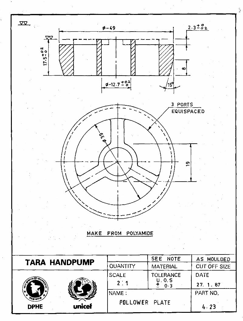
vv0-49
0-12-7 t
3 PORTS
MAKE FROM POLYAMIDE
TARA HANDPUMP QUANTITYSEE NOTEMATERIAL
AS MOULDEDCUTOFF SIZE
DPHE
SCALE
2 : 1TOLERANCE
U.O.S+ 0-3
NAME :
FOLLOWER PLATE
DATE
2 7. 1 . 87
PART NO.
4. 23
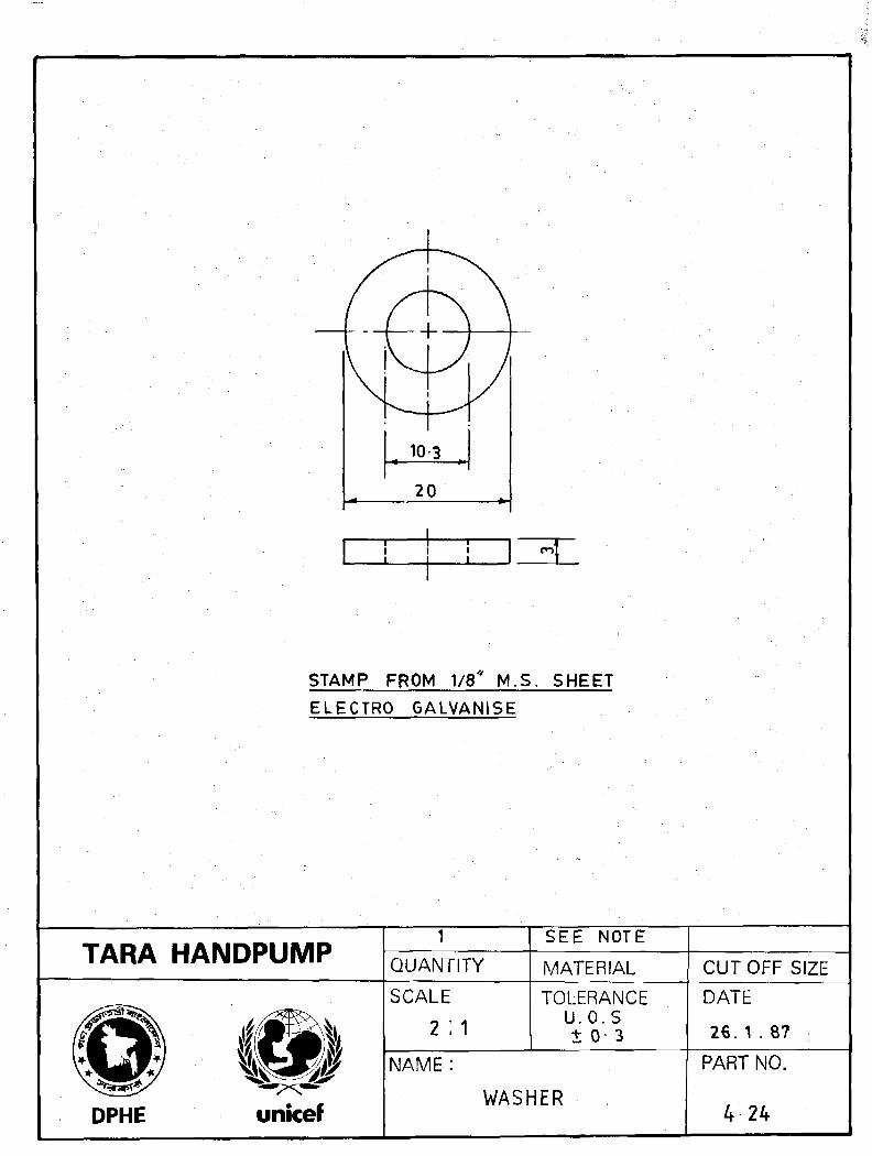
STAMP FROM 1/8* M.S. SHEET
ELECTRO GALVANISE
TARA HANDPUMP
DPHE
1
QUANTITY
SCALE
2 ;
NAME:
SEE NOTE
MATERIAL
TOLERANCEU.O.St 0- 3
WASHER
CUTOFF SIZE
DATE
26. 1 . 87
PART NO.
4 24
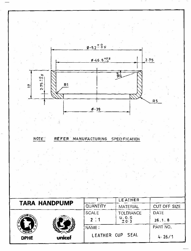
oo•H
R1
+ o1-5 2 - ° - '
0 -A 6 . 5 . Q
0-39
2 75
NOTE: REFER MANUFACTURING SPECIFICATION
TARA HANDPUMP QUANTITYLEATHER
MATERIAL CUTOFF SIZE
DPHE
SCALE
2 :1
TOLERANCEu.o.s±0-3
NAME:
LEATHER CUP SEAL
DATE
2 6 . 1 . 8
PART NO.
4-26/1
TARA HANDPUMP PRODUCTION MANUAL PRODUCTION INFORMATION PAGE B4-10
PISTON ASSEMBLYWITH BOTTOM CONNECTOR
GRAPPLE SUB-ASSEMBLY
Part Noand Name
Production ProcessSequence
Major PorductionMachine Tools/Equipment
Major ProductionAids
CRITICAL ASPECTSof
Production and Inspection
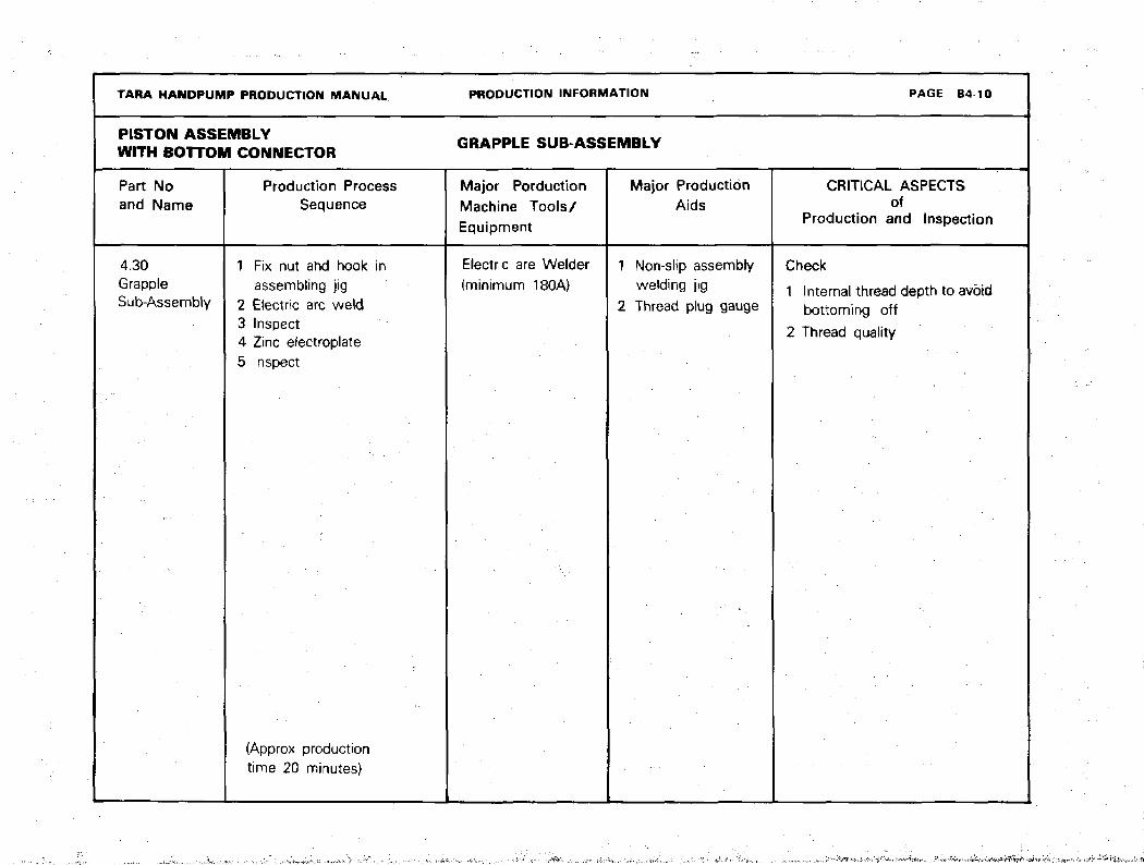
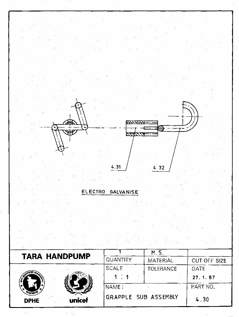
4.30GrappleSub-Assembly
1 Fix nut ahd hook inassembling jig
2 Electric arc weld3 Inspect4 Zinc electroplate5 Inspect
Electric are Welder(minimum 180A)
1 Non-slip assemblywelding jig
2 Thread plug gauge
Check
1 Internal thread depth to avoidbottoming off
2 Thread quality
(Approx productiontime 20 minutes)
TARA HANDPUMP PRODUCTION MANUAL PRODUCTION INFORMATION PAGE B4-11
PISTON ASSEMBLY GRAPPLE SUB-ASSEMBLYWITH BOTTOM CONNECTOR
Part Noand Name
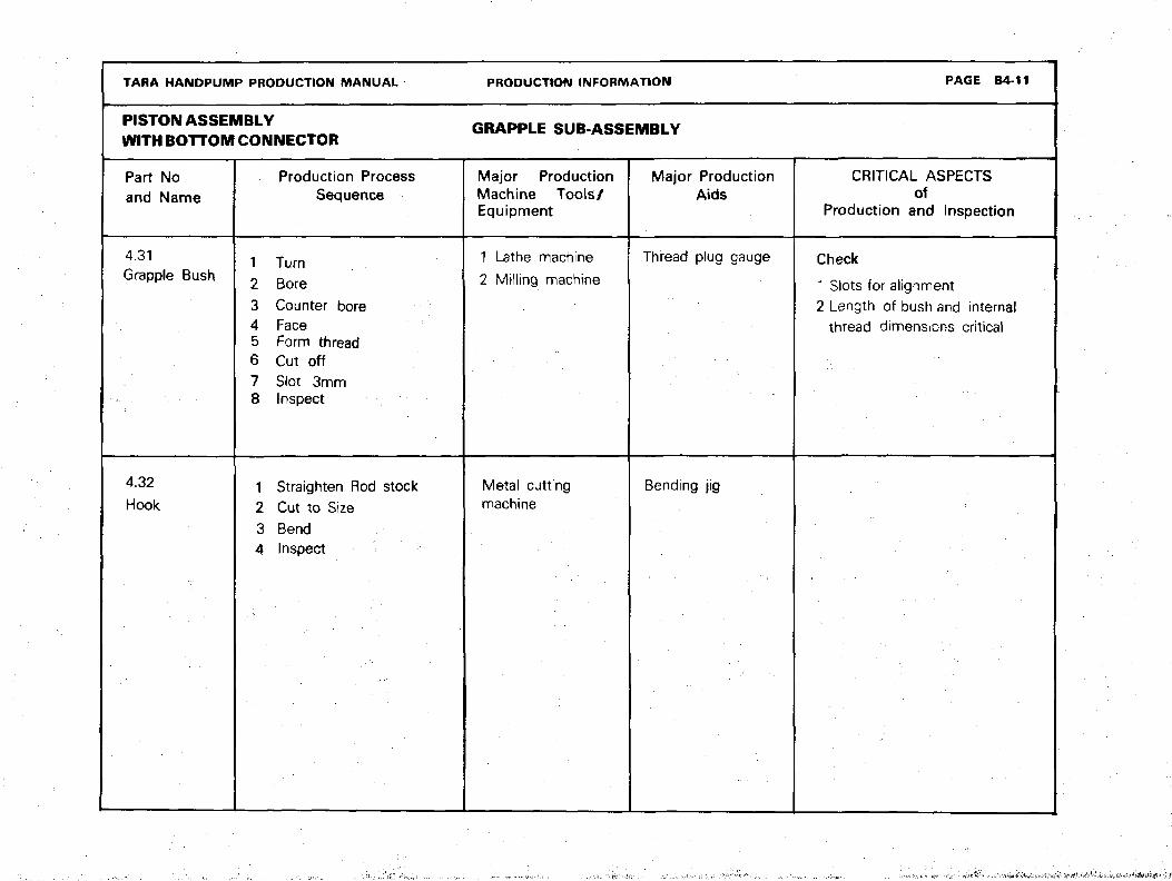
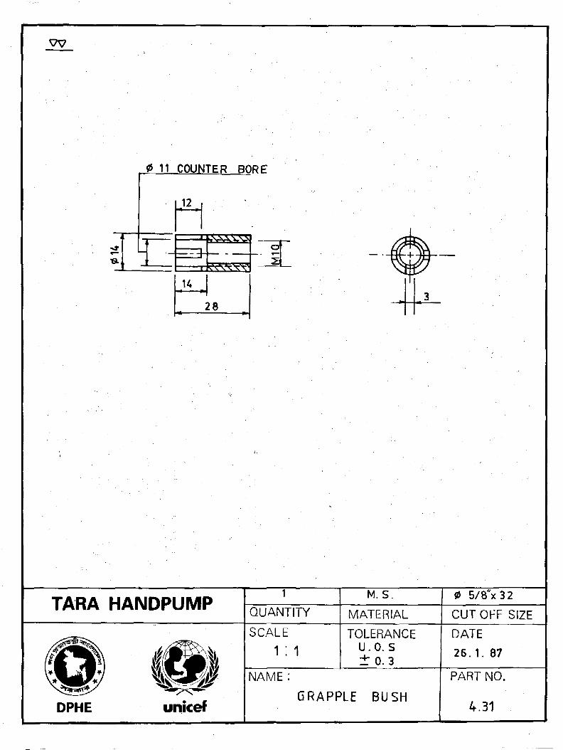
4.31Grapple Bush
4.32
Hook
Production ProcessSequence
1 Turn2 Bore3 Counter bore4 Face5 Form thread6 Cut off7 Slot 3mm8 Inspect
1 Straighten Rod stock2 Cut to Size3 Bend4 Inspect
Major ProductionMachine Tools/Equipment
1 Lathe machine
2 Milling machine
Metal cuttingmachine
Major ProductionAids
Thread plug gauge
Bending jig
CRITICAL ASPECTSof
Production and Inspection
Check
1 Slots for alignment2 Length of bush and internal
thread dimensions critical
•
TARA HANDPUMP PRODUCTION MANUAL PRODUCTION INfORMATION PAGE 84-12 / 1
PISTON ASSEMBLYWITH BOTTOM CONNECTOR GRAPPLE SUB-ASSEMBLY
Part No(Withoutamendment)and Name
Production ProcessSequence
Major ProductionMachine Tools/Equipment
Major ProductionAids
CRITICAL ASPECTSof
Production and Inspection
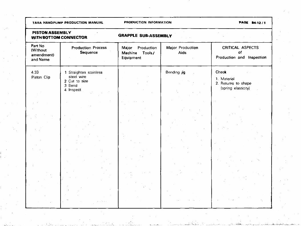
4.33Piston Clip
1 Straighten stainlesssteel wire
2 Cut to size3 Bend4 Inspect
Bending jig Check
1. Material2. Returns to shape
(spring elasticity)
ELECTRO GALVANISE
TARA HANDPUMP TQUANTITY
M.S.MATERIAL CUTOFF SIZE
DPHE
SCALE
1 : 1TOLERANCE
NAME :
GRAPPLE SUB ASSEMBLY
DATE
27. 1. 87
PART NO.
4 . 3 0
0 11 COUNTER BORE
12
H
28
TARA HANDPUMPi
QUANTITY
M.S.
MATERIAL
0 5/8"x32
CUTOFF SIZE
DPHE
SCALE
1 :1TOLERANCE
u.o. s±0.3
NAME :
GRAPPLE BUSH
DATE
26 .1 . 87
PART NO.
4.31

[Hi
TARA HANDPUMP 1QUANTITY
M.SMATERIAL
0 V4" x 13 0
CUTOFF SIZE
SCALE
1:1TOLERANCEU. 0. S± 0-3
NAME :•
DPHE unicef HOOK
DATE
27. 1.87
PART NO.
4 . 3 2

TARA HANDPUMP QUANTITY
STAINLESSSTFR
MATERIAL
16 S.W. G x 100
CUT OFF SIZE
DPHE
SCALE
2 ; 1
TOLERANCEU.O.S.± 0 - 3
NAME:
PISTON CLIP
DATE
27. 1. 87
PART NO.
43 3/1
TARA HANDPUMP PRODUCTION MANUAL PAGE BS-0
. . . .
FOOT VALVE ASSEMBLY
PRODUCTION INFORMATION
DRAWINGS" • - . •
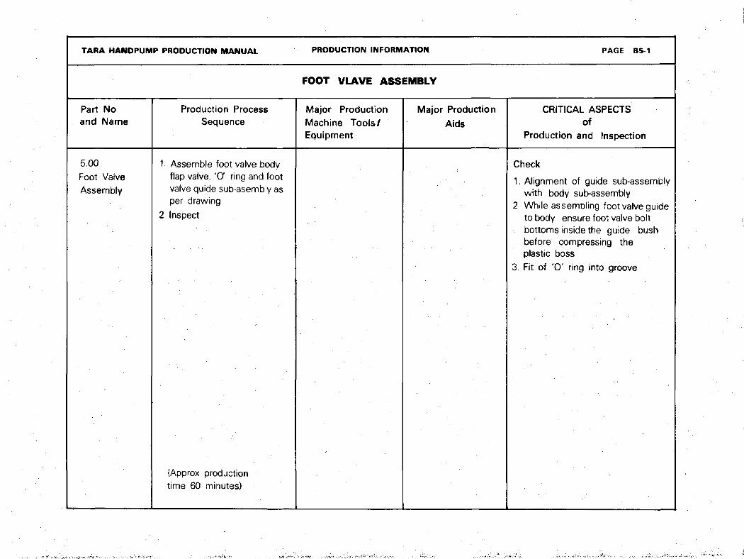
TARA HANDPUMP PRODUCTION MANUAL PRODUCTION INFORMATION PAGE B5-1
FOOT VLAVE ASSEMBLY
Part Noand Name
Production ProcessSequence
Major ProductionMachine Tools/Equipment
Major Production
Aids
CRITICAL ASPECTSof
Production and Inspection
5.00
Foot VafveAssembly
t. Assemble foot vaive bodyflap valve, 'O ring and footvalve quide sub-asembly asper drawing
2 Inspect
(Approx productiontime 60 minutes)
Check
1. Alignment of guide sub-assemblywith body sub-assembly
2 While assembling foot valve guideto body ensure foot valve boltbottoms inside the guide bushbefore compressing theplastic boss
3. Fit of 'O' ring into groove

TARA HANDPUMP QUANTITY MATERIAL CUTOFF SIZE
SCALE
1:1TOLERANCE
DPHE unicef
NAME :
FOOT VALVE ASSEMBLY
DATE
29. 1. 87
PART NO.
5-00
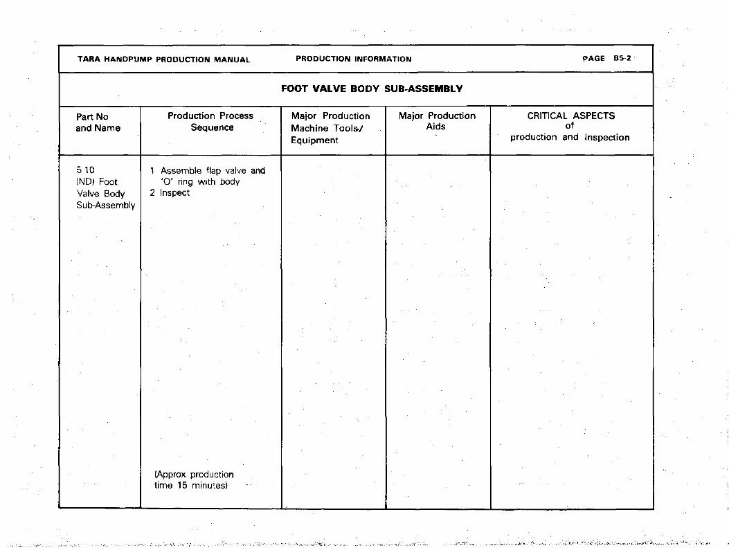
TARA HANDPUMP PRODUCTION MANUAL PRODUCTION INFORMATION PAGE B5-2
FOOT VALVE BODY SUB-ASSEMBLY
Part Noand Name
Production ProcessSequence
Major ProductionMachine Tools/Equipment
Major ProductionAids
CRITICAL ASPECTSof
production and Inspection
5.10(ND) FootValve BodySub-Assembly
1 Assemble flap valve and'0 ' ring with body
2 Inspect
(Approx productiontime 15 minutes)

TARA HANDPUMP PRODUCTION MANUAL PRODUCTION INFORMATION PAGE B5-3
FOOT VALVEASSEMBLY F O O T VALVE BODY SUB-ASSEMBLY
Part No(withoutamendment)and Name
5.11FootValve Body
5.12Bolt
Production ProcessSequence
1 Place bolt (5.12) in die2 Injection mould using HDPE3 Inspect4 Face5 Form groove6 Inspect
1 Procure steel HEX bolt 0.25"BSWx 1,75" minimum20 mm threaded to BS3692-1967 (ISO4016 )
2 Inspect3 Zinc electroplate4 Inspect
Major ProductionMachine Tools/Equipment
1 Injection mouldingmachine
2 Die for injectionmoulding
3 Lathe machine
Major ProductionAids
Feeler gauge
CRITICAL ASPECTSof
Production and Inspection
Check
1 Groove dimensions2 Concentricity of bolt3 Bolt protrusion exactly 20 mm
above plastic boss4 Sealing surface finish of top
of valve ports5 Dimensions of flap valve
retainer groove
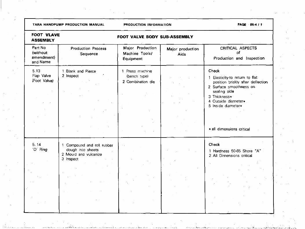
TARA HANDPUMP PRODUCTION MANUAL PRODUCTION INFORMATION PAGE B5-4 / 1
FOOT VLAVE F O O T V A L V E BODY SUB-ASSEMBLYASSEMBLY
Part No(withoutamendment)and Name
5.13Flap Valve(Foot Valve)
5. 14' 0 ' Ring
Production ProcessSequence
1 Blank and Pierce2 Inspect
1 Compound and roll rubberdough into sheets
2 Mould and vulcanize3 Inspect
Major ProductionMachine Tools/Equipment
1 Press machine(bench type)
2 Combination die
Major productionAids
CRITICAL ASPECTSof
Production and Inspection
Check
1 Elasticity-to return to flatposition briskly after deflection
2 Surface smoothness onsealing side
3 Thickness*4 Outside diameter*5 Inside diameter*
* all dimensions critical
Check
1 Hardness 50-65 Shore "A"2 All Dimensions critical

vv 0 53
DETAIL-AScale : 2 ;1 12 PORTS EQUISPACED
BODY TO BE MADE FROM HIGH DENSITY POLYETHYLENE
BOLT TO BE POSITIONED INSIDE DIE DURING MOULDING
TARA HANDPUMPQUANTITY MATERIAL CUTOFF SIZE
I9SSCALE
1: 1TOLERANCE
U. 0. S+• 03
DATE
29.1. 87
DPHE unicef
NAME :
FOOT VALVE BODY
PART NO.
5-11/1

PROCURE GENERAL PURPOSE STEEL HEX-BOLT TO
BS 3692-1967 (ISO 416) ELECTRO GALVANISE
TARA HANDPUMP TQUANTITY
SEE NOTE
MATERIAL CUT OFF SIZE
SCALE TOLERANCE
NAME:
DPHE unicefBOLT
DATE
26. 1.87
PART NO.
5 12
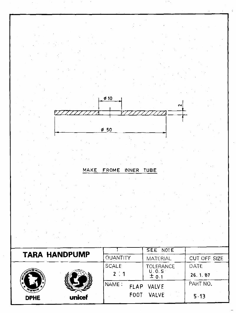
010
Y/////////A Y//////////A
MAKE FROME INNER TUBE
TARA HANDPUMP QUANTITYSEE NOTE
MATERIAL CUTOFF SIZE
DPHE
SCALE
2 :1TOLERANCE
u.o. s±0.1
NAME:F L A p
FOOT VALVE
DATE
26. 1. 87
PART NO.
5-13

0 40
NOTE; MAKE FROM ACRYLONITRILE BUTADIENE RUBBER
BAYER PURBUNAN N 3 3 0 7 N S OR EQUIVALENT
HARDNESS 5 0 - 6 5 SHORE ' A '
TARA HANDPUMPT
QUANTITY
SEE NOTE
MATERIAL
AS MOULDED
CUTOFF SIZE
DPHE
SCALE TOLERANCEu.o.s± 0 3
NAME
unicef0 - RING
DATE
26. 1. 87
PART NO.
5.14/1

TARA HANDPUMP PRODUCTION MANUAL
FOOT VLAVEASSEMBLY
Part Noand Name
5.20FootValve GuideSub-Assembly
Production ProcessSequence
1 Fix guide bush, guide rod.guide and rod in assemblyjig and securely tack weld
2 Remove Sub-Assemblyfrom jig and complete arcwelding as specified
3 Clean thoroughly4 Inspect5 Hot dip galvanize6 Inspect
(Approx Productiontime 40 minutes)
PRODUCTION INFORMATION
FOOT VALVE BODY SUB-ASSEMBLY
Major ProductionMachine Tools/Equipment
1 Electric arc welder(minimum 180A}
2 Hot dip galvanizingbath
Major productionAids
Non-slip assemblywelding jig
PAGE B5-5
CRITICAL ASPECTS
ofProduction and Inspection
Check
1 Concentricity of guide bushwith guide rod
2 Perpendicularity of rodwith guide
3 Central position of rod andgide on guide rod
4 Galvanizing quality(visual check)

TARA HANDPUMP PRODUCTION MANUAL
FOOT VLAVEASSEMBLY
Part Noand Name
5.21Guide Rod
522Rod
PRODUCTION INFORMATION
FOOT VALVE GUIDE
Production ProcessSequence
1 Straighten bar stock2 Chamfer3 Cut off4 Inspect
1 Straighten bar stock2 File sharp corners3 Cut off4 Inspect
Major Production
Machine Tools/Equipment
1 Sawing machine2 Pedestal grinder
Sawing machine
SUB-ASSEMBLY
Major productionAids
Sawing jig
Sawing jig
PAGE B5-6
CRITICAL ASPECTSof
Production and Inspection

TARA HANDPUMP PRODUCTION MANUAL PRODUCTION INFORMATION P A G E B 5 "7
FOOT VALVE GUIDE SUB-ASSEMBLY
Part Noand Name
5.23Guide
5.24FootValve GuideBush
Production ProcessSequence
1 Cut Flat Bar2 Bend in press3 Grind ends4 Inspect
1 Turn2 Face3 Bore4 Form thread5 Cut off6 Inspect
Major ProductionMachine Tools/Equipment
1 Iron worker withshearingattachment
2 Ball press3 Bending die
Lathe machine
Major productionAids
Thread plug gauge
CRITICAL ASPECTSof
Production and Inspection
Check
1 Dimension 50 mm after bendingand grinding end radius
2 Bend location exactlyin centre of flat bar
Check
Dimension 20.5 mm
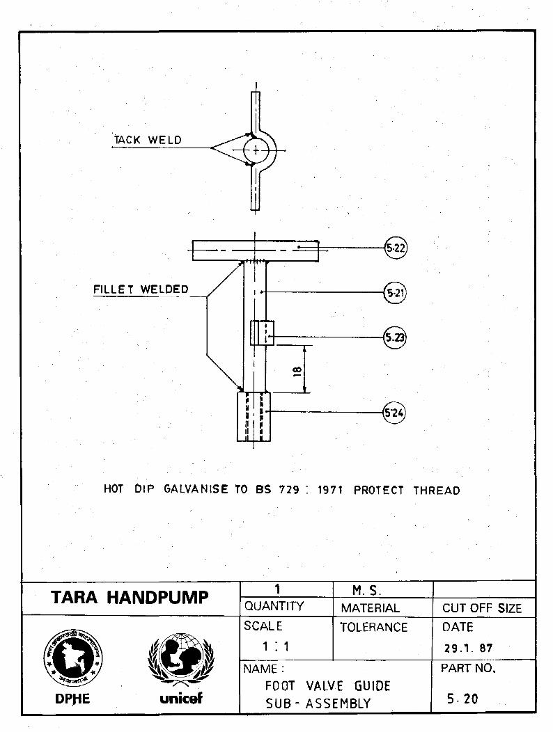
TACK WELD
FILLET WELDED i •
HOT DIP GALVANISE TO BS 729 : 1971 PROTECT THREAD
TARA HANDPUMP 1QUANTITY
M.S.MATERIAL CUT OFF SIZE
SCALE TOLERANCE
DPJiE unicef
NAME :FOOT VALVE GUIDESUB- ASSEMBLY
DATE
29.V 87
PART NO.
5. 20

TARA HANDPUMP1
QUANTITYM.S
MATERIAL0 3/8x55CUTOFF SIZE
DPHE
SCALE
1:1TOLERANCE
U.O.S±o-a
NAME:
GUIDE ROD
DATE
26. 1.87
PART NO.
5.21
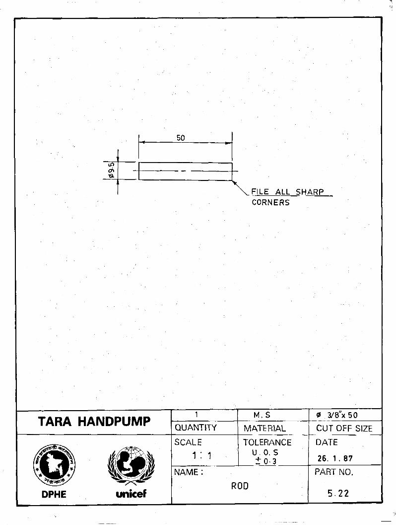
50
IT)OS
FILE ALL SHARPCORNERS
TARA HANDPUMP1
QUANTITY
M.S
MATERIAL
3/8"x50
CUT OFF SIZE
DPHE
SCALE
1 : 1
NAME:
TOLERANCEU.O. S± 0 - 3
ROD
DATE
26. 1 . 87
PART NO.
5 2 2
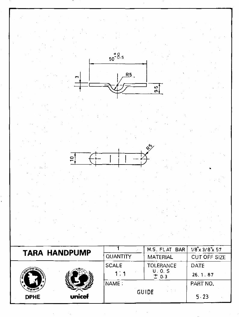
TARA HANDPUMP
DPHE unicef
1
QUANTITY
SCALE
1:1
NAME:
M.S. FLAT BARMATERIAL
TOLERANCEU. 0. St 0-3
GUIDE
1/8 x 3/8 x 57CUT OFF SIZE
DATE
26. 1 . 87
PART NO.
5-23
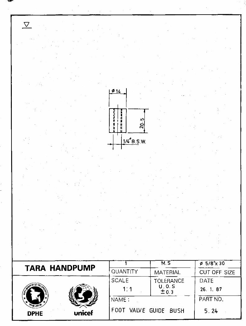
V
IHItH
1llVu11ll
in
org
1/4 B.S.W.
TARA HANDPUMP QUANTITY
M.S
MATERIAL
0 5/8 'x 30
CUTOFF SIZE
SCALE
1:1
TOLERANCE
u.o. s±0.3
DATE26. 1. 87
DPHE unicef
NAME :
FOOT VALVE GUIDE BUSH
PART NO.
5.24

TARA HANDPUMP PRODUCTION MANUAL PAGE B6-0
. • r
•
• - "
CYLINDER ASSEMBLY
PRODUCTION INFORMATION
DRAWINGS _
•
•

TARA HANDPUMP
Part No(withoutamendment)and Name
6.00CylinderAssembly
1
2
3
4
b6/
PRODUCTION MANUAL
Production ProcessSequence
Clean thoroughly surfaces ofapplication preferably byacetoneApply PVC solvent cementon mating surfaces inuniform thicknessAssemble bell connectorinside cylinder pipeProvide specifiedsetting timeInspectFix rubber seat*Inspect
(Approx Productiontime 20 minutes)
PRODUCTION INFORMATION
ASSEMBLY CYLINDER
Major ProductionMachine Tools/Equipment
* for extractablemode only
Major productionAids
1
2
3
456
PAGE B6-1 ' 1
CRITICAL ASPECTSof
Production and Inspection
Tolerances and fits of matingsurfaces for correct filmthicknessFor cleanliness of surfacesof applicationSolvent cement film for continuityand uniformitySurface finishScrew properly countersunk*Screws do not protrude more thanon ID of cylinder*

TARA HANDPUMP PRODUCTION MANUAL
Part Noand Name
6.11Cylinderpipe
6.12BellConnector
Production ProcessSequence
1 Cut to size2 Heat uniformly the section
of pipe to be formed3 Roll and gradually press
the hot section of pipe informing die for constrictionforming
4 Cool5 Inspect6 Apply glass fibre reinforced
resin band on outside ofconstricted protion of pipe
7 Provide setting time8 inspect
1 Cut to size2 Heat pipe end in oil3 Press on flaring die
for forming4 Cool5 Remove from die6 Cut to size7 Inspect
PRODUCTION INFORMATION
CYLINDER ASSEMBLY
Major Production
Machine Tools/Equipment
1 Band saw orCircular saw orHacksaw
2 Heating equipment3 Crimping die
1 Band saw orCircular saw orHacksaw
2 Heating equipment3 Flaring die
Major productionAids
PAGE B6-2
CRITICAL ASPECTSof
Production and Inspection
Check
1 Pipe for dimension tolerancesspecified in drawing and forinternal smooth finish
2 Straightness of pipe afterforming constriction
3 Dimensions of constrictionbefore applying glass fibrereinforced resin
4 Correct storage aftermanufacture to avoidinduced bending
CheckOutside and inside diameterof finished flared portion*
*NB. Dimensions critical

TARA HANDPUMP PRODUCTION MANUAL PRODUCTION INFORMATION PAGE B6-3
CYLINDER ASSEMBLY
Part Noand Name
Production ProcessSequence
Major ProductionMachine Tools/Equipment
Major ProductionAids
CRITICAL ASPECTSof
Production and Inspection
6.13RubberSeat
1 Compound androll rubberdough into sheets
2 Mould and vulcanize3 Inspect
1 Printing roller2 Press machine3 Die mould
Check
1 Hardness 60-75 Shore "A"2 Internal diameter
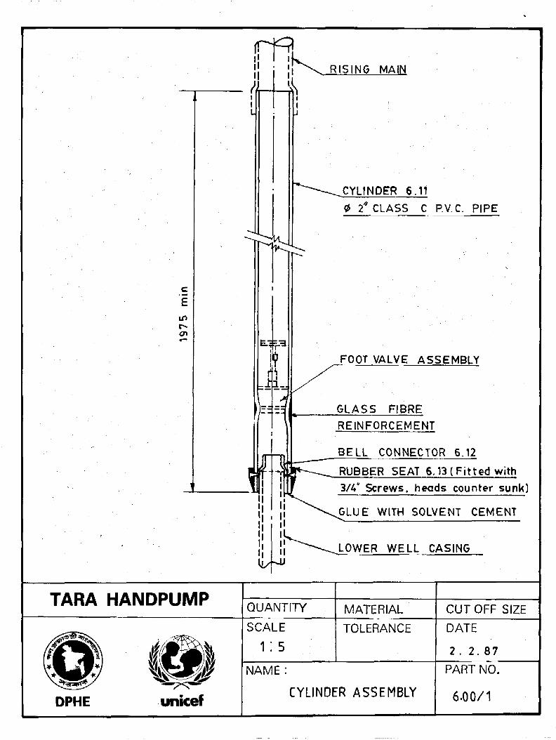
CYLINDER 6.11
2 CLASS C P.V.C. PIPE
FOOT VALVE ASSEMBLY
GLASS FIBRE
REINFORCEMENT
BELL CONNECTOR 6.12
RUBBER SEAT 6.13 ( Fi t ted with
3/4* Screws, heads counter sunk)
GLUE WITH SOLVENT CEMENT
LOWER WELL CASING
TARA HANDPUMPQUANTITY MATERIAL CUTOFF SIZE
DPHE
municef
SCALE
1:5TOLERANCE DATE
2 . 2 . 8 7
NAME:
CYLINDER ASSEMBLY
PART NO.
6.00/1

WATER GRADE CLASS "C " P.V.C PIPE TO BS 3505 WITH INTERNAL
DIAMETER AND WALL THICKNESS TOLERANCES AS INDICATED
TARA HANDPUMP QUANTITYSEE NOTE
MATERIAL
0 2x2000CUTOFF SIZE
DPHE
SCALE
1; 1TOLERANCE
U-0. S± 1 - 0
DATE
29. 1. 87
NAME :
CYLINDER PIPE
PART NO.
6.11
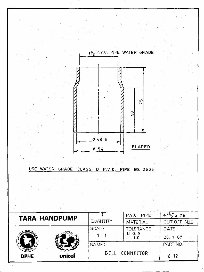
a
P.V.C. PIP
48-5
0 54
? WATER GRADE
o
FLARED
USE WATER GRADE CLASS D P.V.C. PIPE BS 3505
TARA HANDPUMP 1QUANTITY
P.V.C. PIPEMATERIAL
0 1 '/2 x 7 5CUTOFF SIZE
DPHE unicef
SCALE
1 :1TOLERANCEu.o. s± 1-0
NAME :
BELL CONNECTOR
DATE
26. 1. 87
PART NO.
6.12

in
0 80
0 60
NOTE:
MAKE FROM ACRYLONITRILE BUTADIENE RUBBER BAYER PERBUNAN
N3307 NS OR EQUIVALENT HARDNESS 5 5 - 7 0 SHORE " A "
TARA HANDPUMPi
QUANTITYSEE NOTE
MATERIAL
AS MOULDED
CUTOFF SIZE
DPHE unicef
SCALE
1:1TOLERANCE
± 0-5NAME:
RUBBER SEAT
DATE
26. 1. 87
PART NO.
6.13
TARA HANDPUMP PRODUCTION MANUAL PAGE 87 0
TUBEWELL ASSEMBLY
PRODUCTION INFORMATION
DRAWINGS

TARA HANDPUMP PRODUCTION MANUAL PRODUCTION INFORMATION PAGE B7-1
TUBEWELL ASSEMBLY
Part No
and NameProduction Process
SequenceMajor ProductionMachine Tools/Equipment
Major ProductionAids
CRITICAL ASPECTSof
Production and inspection
7.00<ND>TubewellAssembly
Refer to installationinstructions
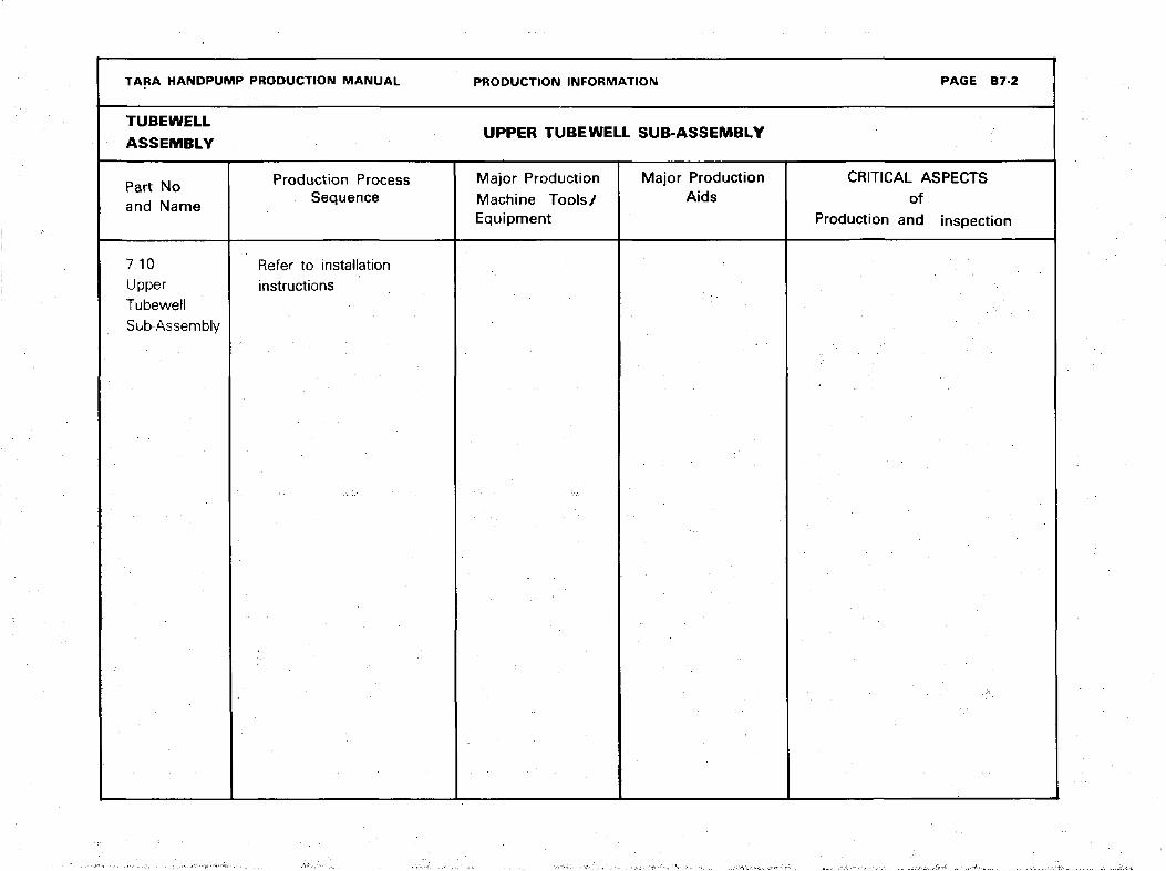
TARA HANDPUMP PRODUCTION MANUAL PRODUCTION INFORMATION PAGE B7 2
TUBEWELL
ASSEMBLYUPPER TUBEWELL SUB-ASSEMBLY
Part Noand Name
Production ProcessSequence
Major Production
Machine Tools/Equipment
Major ProductionAids
CRITICAL ASPECTSof
Production and inspection
7.10UpperTubewetlSub-Assembly
Refer to installationinstructions
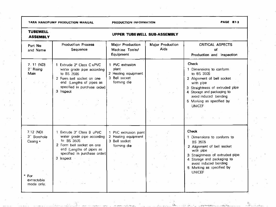
TARA HANDPUMP PRODUCTION MANUAL
TUBEWELL
ASSEMBLY
Part Noand Name
7. 11 <ND)2"- RisingMain
7.12 (ND>3" BoreholeCasing *
* Forextractablemode only.
Production ProcessSequence
1 Extrude 2" Class C uPVCwater grade pipe accordingto BS 3505
2 Form bell socket on oneend (Lengths of pipes asspecified in purchase order)
3 Inspect
1 Extrude 3" Class B uPVCwater grade pipe accordingto BS 3505
2 Form bell socket on oneend (Lengths of pipes asspecified in purchase order)
3 Inspect
PRODUCTION INFORMATION
UPPER TUBEWELL SUB-ASSEMBLY
Major Production
Machine Tools/Equipment
1 PVC extrusionplant
2 Heating equipment3 Bell socket
forming die
1 PVC extrusion plant2 Heating equipment3 Bell socket
forming die
Major ProductionAids
PAGE B7-3
CRITICAL ASPECTSof
Production and Inspection
Check
1 Dimensions to conformto BS 3505
2 Alignment of bell socketwith pipe
3 Straightness of extruded pipe4 Storage and packaging to
avoid induced bending5 Marking as specified by
UNICEF
Check
1 Dimensions to conform toBS 3505
2 Alignment of bell socketwith pipe
3 Straightness of extruded pipe4 Storage and packaging to
avoid induced bending5 Marking as specified by
UNICEF
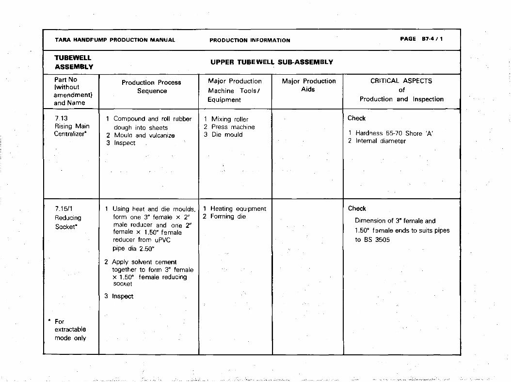
TARA HANDPUMP
TUBEWELLASSEMBLY
Part No
(withoutamendment)and Name
7.13Rising MainCentralized
7.15/1ReducingSof*kpt*
* Forextractablemode only
1
23
1
2
3
PRODUCTION MANUAL
Production ProcessSequence
Compound and roll rubberdough into sheetsMould and vulcanizeInspect
Using heat and die moulds.form one 3" female x 2"male reducer and one 2"female x 1.50" femalereducer from uPVCpipe dia 2.50"
Apply solvent cementtogether to form 3" femalex 1.50" female reducingsocket
Inspect
123
12
PRODUCTION IN FORMATION
UPPER TUBEWELL SUB-ASSEMBLY
Major Production
Machine Tools/Equipment
Mixing rollerPress machineDie mould
Heating equipmentForming die
Major ProductionAids
PAGE B7-4 / 1
CRITICAL ASPECTSof
Production and Inspection
Check
1 Hardness 55-70 Shore 'A'2 Internal diameter
Check
Dimension of 3" female and
1.50" female ends to suits pipesto BS 3505
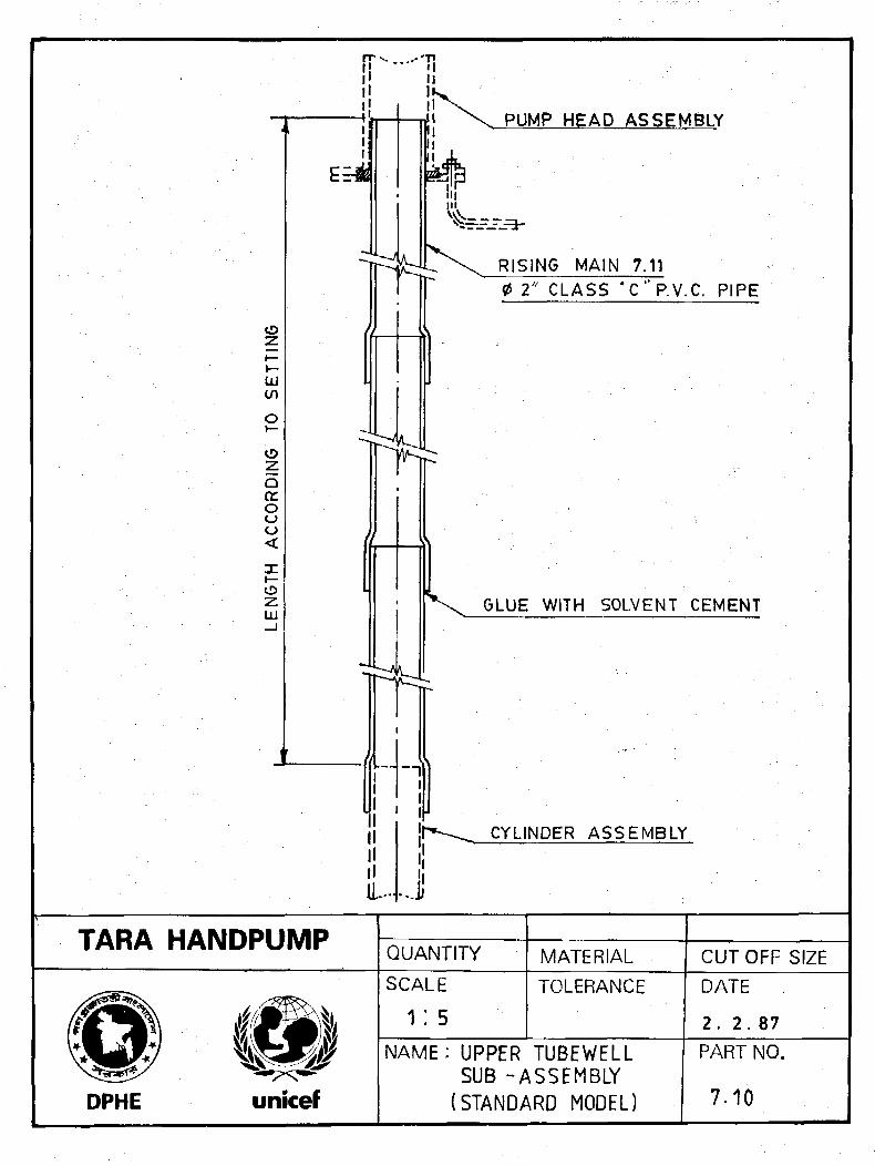
ir T!II
t/1
oQa:oo
oz:LU
PUMP HEAD ASSEMBLY
1".
..J
RISING MAIN 7.110 2" CLASS *C"P.V.C. PIPE
GLUE WITH SOLVENT CEMENT
CYLINDER ASSEMBLY
TARA HANDPUMPQUANTITY MATERIAL CUTOFF SIZE
DPHE
SCALE
1:5TOLERANCE DATE
2. 2 .87
NAME: UPPER TUBEWELLSUB -ASSEMBLY
(STANDARD MODEL)
PART NO.
7.10
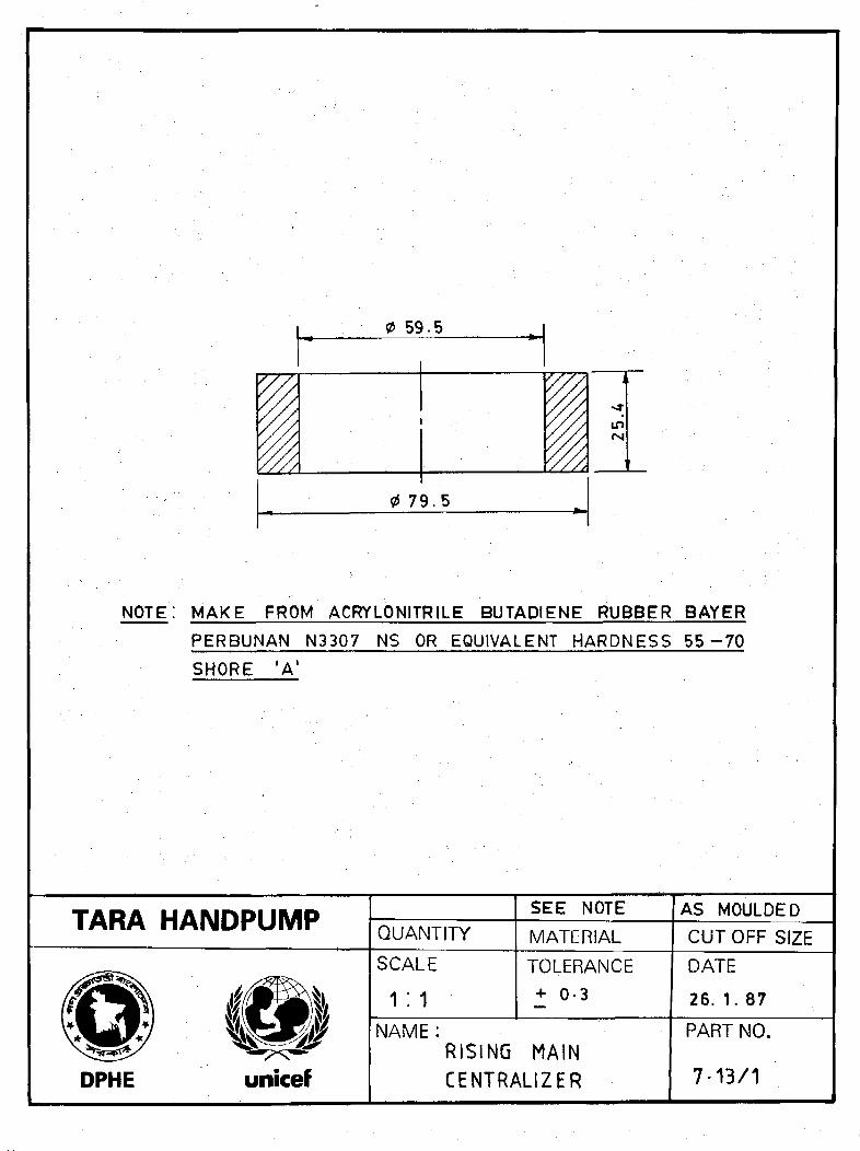
0 59.5
0 79.5
IDfM
NOTE: MAKE FROM ACRYLONITRILE BUTADIENE RUBBER BAYER
PERBUNAN N33Q7 NS OR EQUIVALENT HARDNESS 5 5 - 7 0
SHORE 'A1
TARA HANDPUMPQUANTITY
SEE NOTE
MATERIAL
AS MOULDED
CUT OFF SIZE
DPHE
SCALE
1:1
TOLERANCE
+ 0-3
NAME:RISING MAINCENTRALIZER
DATE
26. 1. 87
PART NO.
7-13/1

SOCKET ID TO SUIT OP OF
0 3* CLASS B P.V.C. PIPE
BS 3505
MOULDED FROM 0P.V.C. PIPE
-©
GLUE WITH SOLVENT CEMENT
48-3-o2S0CKET ID TO SUIT OP OF0 1V2" P.V.C. PIPE BS 350 5
TARA HANDPUMP 1QUANTITY
P.V.C. PIPE
MATERIAL CUT OFF SIZE
SCALE
V. 2TOLERANCE
DPHE unicef
NAME :
REDUCING SOCKET
DATE
31. 1. 87
PART NO.
7*15/1

TARA HANDPUMP PRODUCTION MANUAL PRODUCTION INFORMATION PAGE B7-6
TUBE WELLASSEMBLY
RETRIEVING ROD ASSEMBLY
Part No
and Name
Production ProcessSequence
Major ProductionMachine Tools/Equipment
Major ProductionAids
CRITICAL ASPECTSof
Inspection Production and
7.20LowerTubewllSub-assembly
Refer to installation
instructions
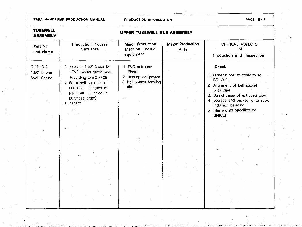
TARA HANDPUMP PRODUCTION MANUAL PRODUCTION INFORMATION PAGE B7-7
TUBEWELLASSEMBLY
UPPER TUBEWELL SUB-ASSEMBLY
Part No
and Name
Production ProcessSequence
Major ProductionMachine Tools/Equipment
Major Production
AidsCRITICAL ASPECTS
of
Production and Inspection
7.21 (ND)
1.50" Lower
Well Casing
Extrude 1.50" Class DuPVC water grade pipeaccording to BS 3505Form bell socket onone end (Lengths ofpipes as specified inpurchase order)Inspect
1 PVC extrusionPlant
2 Heating equipment3 Bell socket forming
die
Check
1 . Dimenstions to conform toBS' 3505
2. Alignment of bell socketwith pipe
3. Straightness of extruded pipe4 Storage and packaging to avoid
induced bending5 Marking as specified by
UNICEF
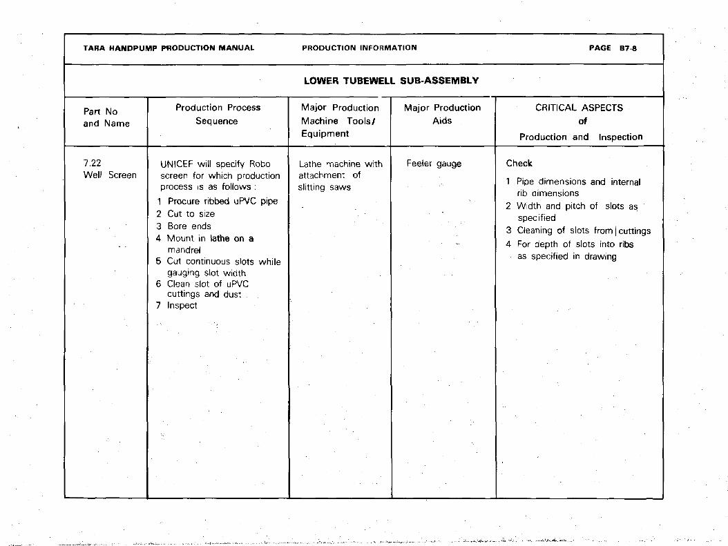
TARA HANDPUMP PRODUCTION MANUAL
Part Noand Name
7.22Well Screen
Production Process
Sequence
UNICEF will specify Roboscreen for which productionprocess is as follows :
1 Procure ribbed uPVC pipe
2 Cut to size3 Bore ends4 Mount in lathe on a
mandrel5 Cut continuous slots while
gauging slot width6 Clean slot of uPVC
cuttings and dust7 Inspect
PRODUCTION INFORMATION
LOWER TUBEWELL SUB-ASSEMBLY
Major Production
Machine Tools/Equipment
Lathe machine withattachment ofslitting saws
Major ProductionAids
Feeler gauge
PAGE B7-8
CRITICAL ASPECTS
of
Production and Inspection
Check
1 Pipe dimensions and internalrib dimensions
2 Width and pitch of slots asspecified
3 Cleaning of slots from [ cuttings
4 For depth of slots into ribsas specified in drawing

TARA HANDPUMP PRODUCTION MANUAL PRODUCTION INFORMATION PAGE B7-9
TUBEWELLASSEMBLY LOWER TUBEWELL SUB-ASSEMBLY
Part Noand Name
7.23 (ND)Sand Trap
7.24End Cap
Production ProcessSequence
1 Use specified length ofStandard 1.50" Class DuPVC pipe similar topart number 7.21
2 Inspect
1 Compression mould inpreheated die with a hardplastic compund
2 Inspect
Major ProductionMachine Tools/Equipment
} Hand injectionmoulding machine
2 Die mould
Major ProductionAids
CRITICAL ASPECTSof
Production and Inspection
Check
Taper dimensions
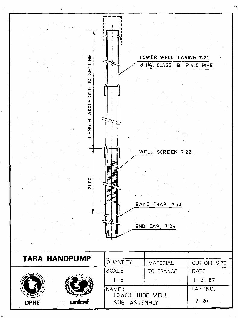
LOWER WELL CASING 7 2 1
<* 1V2* CLASS B P.V.C. PIPE
WELL SCREEN 7.22
SAND TRAP, 7.23
END CAP, 7.24
TARA HANDPUMP QUANTITY MATERIAL CUTOFF SIZE
SCALE TOLERANCE
DPHE
NAME :LOWER TUBE WELLSUB ASSEMBLY
DATE
1. 2. 87
PART NO.
7. 20
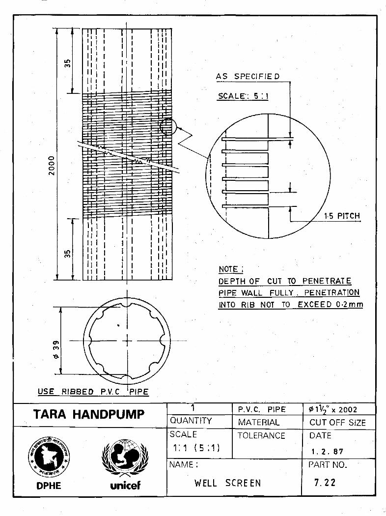
AS SPECIFIED
USE RIBBED P.V.C PIPE
DEPTH OF CUT TO PENETRATE
PIPE WALL FULLY . PENETRATION
INTO RIB NOT TO EXCEED 0-2mm
TARA HANDPUMPQUANTITY
P.V.C. PIPE
MATERIAL7* X2002
CUTOFF SIZESCALE
1:1 ( 5 ; 1)TOLERANCE DATE
1. 2 . 87
DPHE unicef
NAME :
WELL SCREEN
PART NO.
7.22

TARA HANDPUMP TQUANTITY
P. V. C.
MATERIAL
AS MOULDED
CUTOFF SIZE
DPHE
SCALE
1:1TOLERANCEU . 0. S.± 0-3
NAME :
END CAP
DATE
25. 1. 87
PART NO.
7.24
TARA HANDPUMP PRODUCTION MANUAL PAGE B84>
RETRIEVING ROD
ASSEMBLY
PRODUCTION INFORMATION
DRAWINGS

TARA HANDPUMP PRODUCTION MANUAL PRODUCTION INFORMATION PAGE B8-1
RETRIEVING ROD ASSEMBLY
Part No
and Name
Production Process
Sequence
Major ProductionMachine Tools/Equipment
Major Production
AidsCRITICAL ASPECTS
ofproduction and inspection
8.00Retrieving RodAssembly
1 Weld nut with rod as perassembly drawing
2 Clean welded joint3 Inspect4 Clean and paint with
red oxide5 Inspect
Electric arc welder
(Minimum 180A)
Thread gauge Check
1 Alignment of nut with rod2 Thread quality
(Approx production
time 35 minutes)

TARA HANDPUMP PRODUCTION MANUAL PRODUCTION INFORMATION PAGE B8-2
ASSEMBLY RETRIEVING ROD ASSEMBLY
Part Noand Name
8.11
(ND) Rod
8.12
(ND) Nut
Production Process
Sequence
1 Straighten bar stock2 Chamfer3 Cut off4 Bend5 InsDect
1 Turn2 Face3 Bore4 i Form thread5 Cut off6 Inspect
Major ProductionMachine tools/Equipment
Lathe machine
Lathe machine
Major Production
Aids.
Bending Jig
Thread Plug gauge
CRITICAL ASPECTSof
Production and Inspection
Check
Thread for mating with topconnector bolt (Part 3.12)
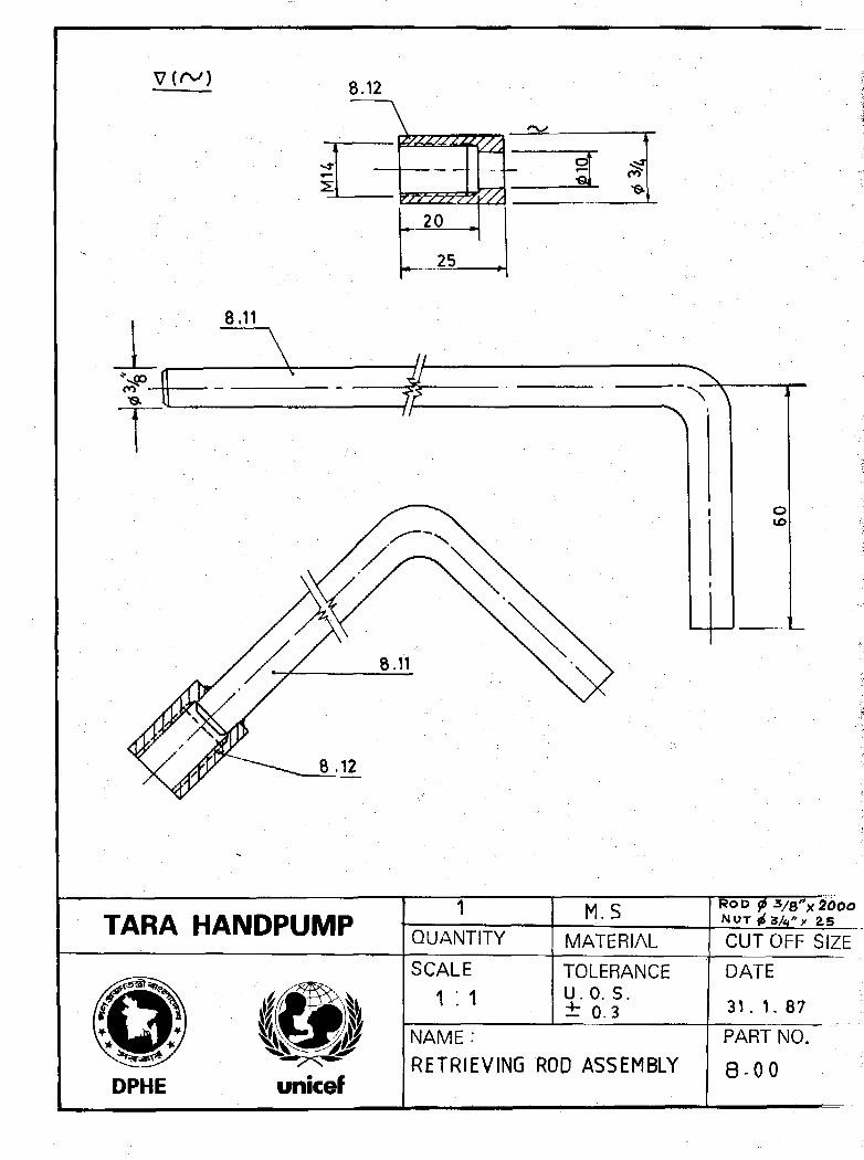
8.12
8.11
20
25
TARA HANDPUMP QUANTITY
M.S
MATERIALN O T
CUTOFF SIZE
SCALE TOLERANCEU . 0. S.± 0.3
DPHE unicef
NAME :
RETRIEVING ROD ASSEMBLY
DATE
31. 1. 87
PART NO.
8 - 0 0
TARA HANDPUMP PRODUCTION MANUAL PAGE R-0
AMENDMENT RECORD SYSTEM
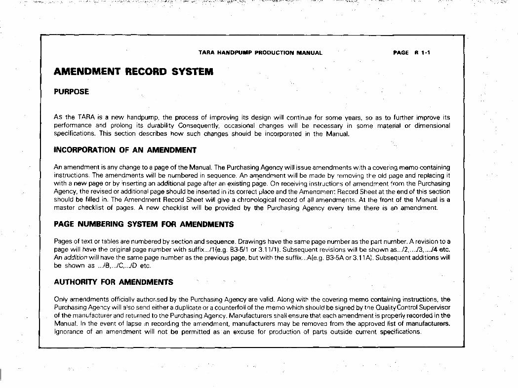
TARA HANDPUMP PRODUCTION MANUAL PAGE R 1-1
AMENDMENT RECORD SYSTEM
PURPOSE
As the TARA is a new handpump, the process of improving its design will continue for some years, so as to further improve itsperformance and prolong its durability Consequently, occasional changes will be necessary in some material or dimensionalspecifications. This section describes how such changes shouid be incorporated in the Manual.
INCORPORATION OF AN AMENDMENT
An amendment is any change to a page of the Manual. The Purchasing Agency will issue amendments with a covering memo containinginstructions. The amendments will be numbered in sequence. An amendment will be made by removing the old page and replacing itwith a new page or by inserting an additional page after an existing page. On receiving instructions of amendment from the PurchasingAgency, the revised or additional page should be inserted in its correct place and the Amendment Record Sheet at the end of this sectionshould be filled in. The Amendment Record Sheet will give a chronological record of all amendments. At the front of the Manual is amaster checklist of pages. A new checklist will be provided by the Purchasing Agency every time there is an amendment.
PAGE NUMBERING SYSTEM FOR AMENDMENTS
Pages of text or tables are numbered by section and sequence. Drawings have the same page number as the part number. A revision to apage will have the original page number with suffix.../1 (e.g. B3-5/1 or 3.11/1). Subsequent revisions will be shown as.../2,..../3 /4 etc.An addition will have the same page number as the previous page, but with the suffix...A(e.g. B3-5Aor 3.11A). Subsequent additions willbe shown as .../B,.../C,.../D etc.
AUTHORITY FOR AMENDMENTS
Only amendments officially authorised by the Purchasing Agency are valid. Along with the covering memo containing instructions, thePurchasing Agency will also send either a duplicate or a counterfoil of the memo which should be signed by the Quality Control Supervisorof the manufacturer and returned to the Purchasing Agency. Manufacturers shall ensure that each amendment is properly recorded in theManual. In the event of lapse in recording the amendment, manufacturers may be removed from the approved list of manufacturers.Ignorance of an amendment will not be permitted as an excuse for production of parts outside current specifications.
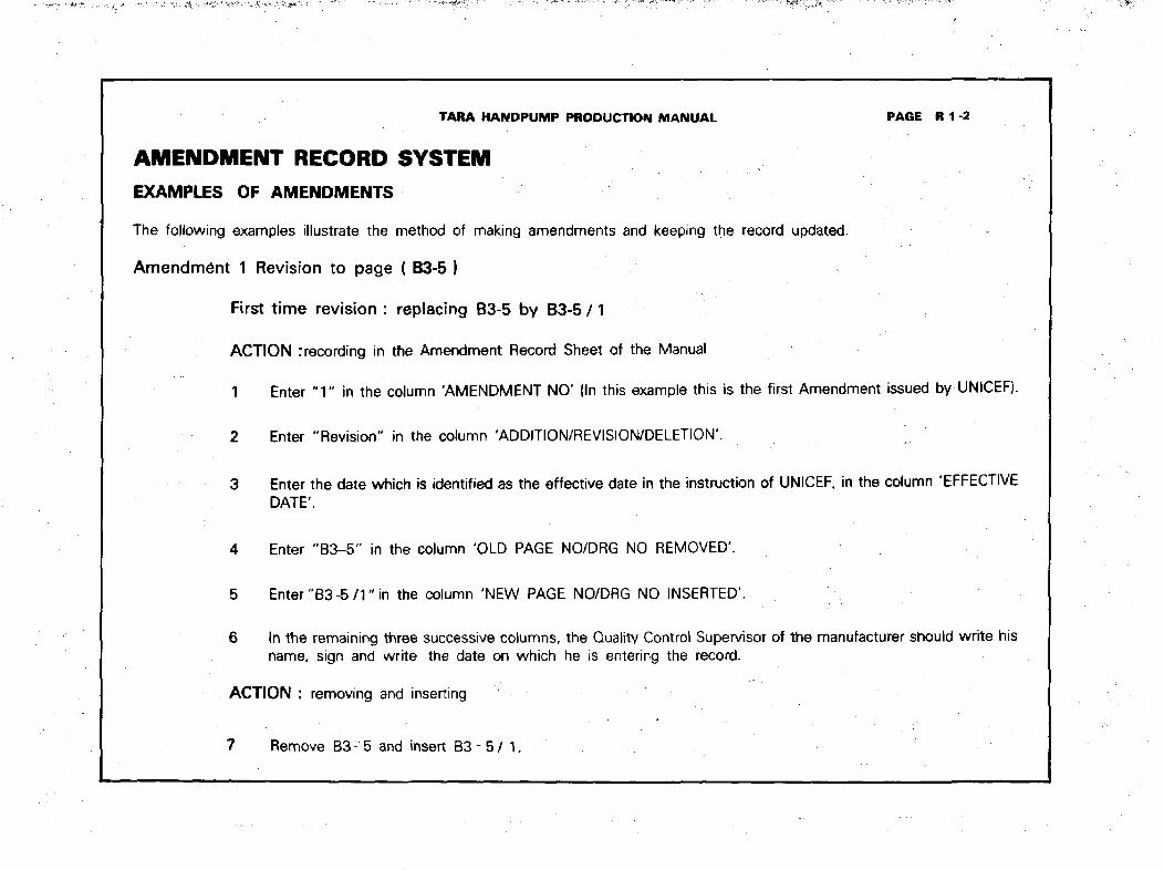
TARA HANDPUMP PRODUCTION MANUAL PAGE Rl-2
AMENDMENT RECORD SYSTEM
EXAMPLES OF AMENDMENTS
The following examples illustrate the method of making amendments and keeping the record updated.
Amendment 1 Revision to page ( B3-5 }
First time revision : replacing B3-5 by B3-5 / 1
ACTION :recording in the Amendment Record Sheet of the Manual
1 Enter " 1 " in the column 'AMENDMENT NO' (In this example this is the first Amendment issued by UNICEF).
2 Enter "Revision" in the column 'ADDITION/REVISION/DELETION'.
3 Enter the date which is identified as the effective date in the instruction of UNICEF, in the column 'EFFECTIVEDATE'.
4 Enter "B3-5" in the column 'OLD PAGE NO/DRG NO REMOVED'.
5 Enter " B 3 - 5 / 1 " in the column 'NEW PAGE NO/DRG NO INSERTED'.
6 In the remaining three successive columns, the Quality Control Supervisor of the manufacturer should write hisname, sign and write the date on which he is entering the record.
ACTION : removing and inserting !
7 Remove B3 - 5 and insert B3 - 5 / 1 .
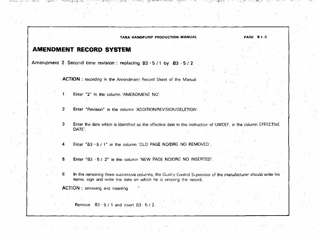
TARA HANDPUMP PRODUCTION MANUAL PAGE R 1 3
AMENDMENT RECORD SYSTEM
Amendment 2 Second time revision: replacing B3 - 5 /1 by B3 - 5 / 2
ACTION : recording in the Amendment Record Sheet of the Manual
1 Enter "2 " in the column 'AMENDMENT NO'.
2 Enter "Revision" in the column 'ADDITION/REVISION/DELETION'.
3 Enter the date which is identified as the effective date in the instruction of UNSCEF, in the column EFFECTIVEDATE'.
4 Enter " B 3 - 5 / 1" in the column 'OLD PAGE NO/DRG NO REMOVED'.
5 Enter "B3 - 5 / 2" in the column 'NEW PAGE NO/DRG NO INSERTED'.
6 In the remaining three successive columns, the Quality Control Supervisor of the manufacturer should write hisname, sign and write the date on which he is entering the record.
ACTION : removing and inserting *
Remove B3 - 5 / 1 and insert B3 - 5 / 2.
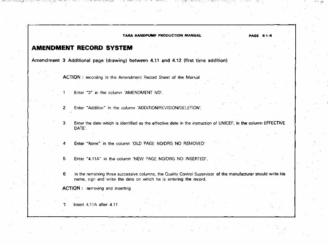
TARA HANDPUMP PRODUCTION MANUAL PAGE R 1 -4
AMENDMENT RECORD SYSTEM
Amendment 3 Additional page (drawing) between 4.11 and 4.12 (first time addition)
ACTION : recording in the Amendment Record Sheet of the Manual
1 Enter "3" in the column 'AMENDMENT NO'.
2 Enter "Addftion" in the column 'ADDITION/REVISION/DELETION'.
3 Enter the date which is identified as the effective date in the instruction of UNICEF, in the column EFFECTIVEDATE1.
4 Enter "None" in the column 'OLD PAGE NO/DRG NO REMOVED'
5 Enter "4.11A" in the column 'NEW PAGE NO/DRG NO INSERTED'.
6 In the remaining three successive columns, the Quality Control Supervisor of the manufacturer should write hisname, sign and write the date on which he is entering the record.
ACTION : removing and inserting
1 Insert 4.11 A after 4.11
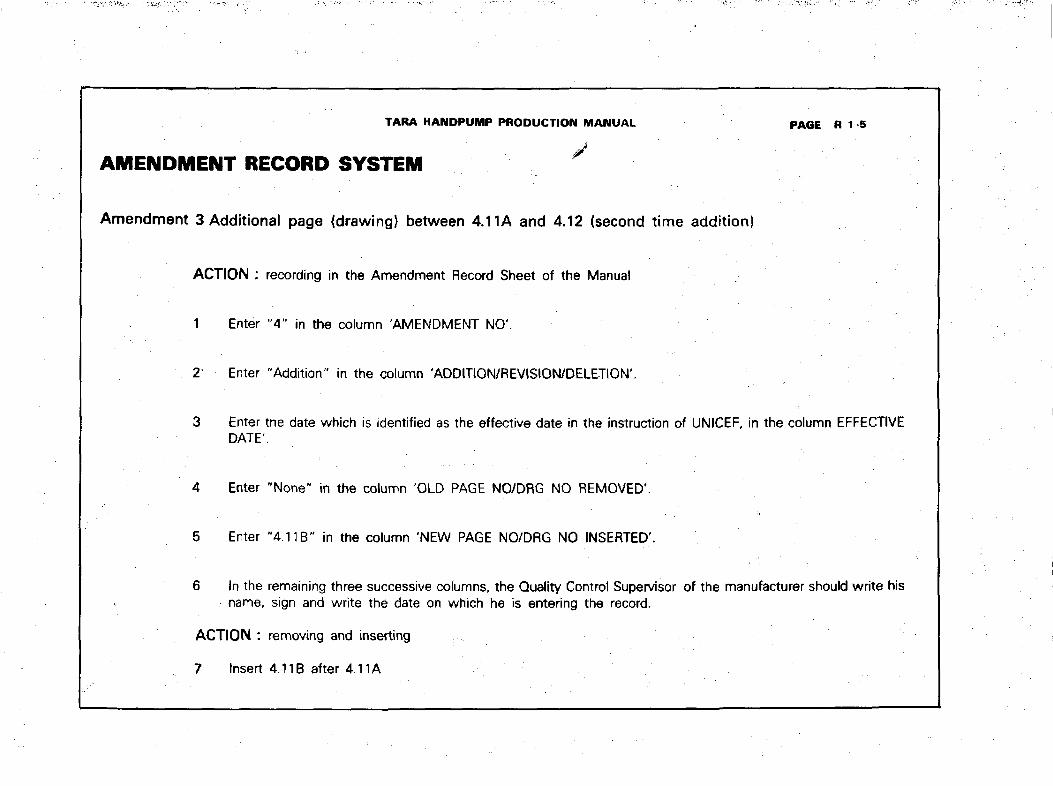
TARA HANDPUMP PRODUCTION MANUAL PAGE R 1 5
AMENDMENT RECORD SYSTEM '
Amendment 3 Additional page {drawing} between 4.11 A and 4.12 (second time addition)
ACTION :
1
2
3
4
5
6
Enter
Enter
EnterDATE
Enter
Enter
In thename.
ACTION :
7 Insert
recording in the Amendment Record Sheet of the Manual
"4" in the column 'AMENDMENT NO'.
"Addition" in the column 'ADDITION/REVISION/DELETION'.
the date which is identified as the effective date in the instruction of UNICEF, in the column EFFECTIVE
"None" in the column 'OLD PAGE NO/DRG NO REMOVED'.
"4.1 IB" in the column 'NEW PAGE NO/DRG NO INSERTED'.
remaining three successive columns, the Quality Control Supervisor of the manufacturer should write hissign and write the date on which he is entering the record.
removing and inserting
4.11B after 4.11A
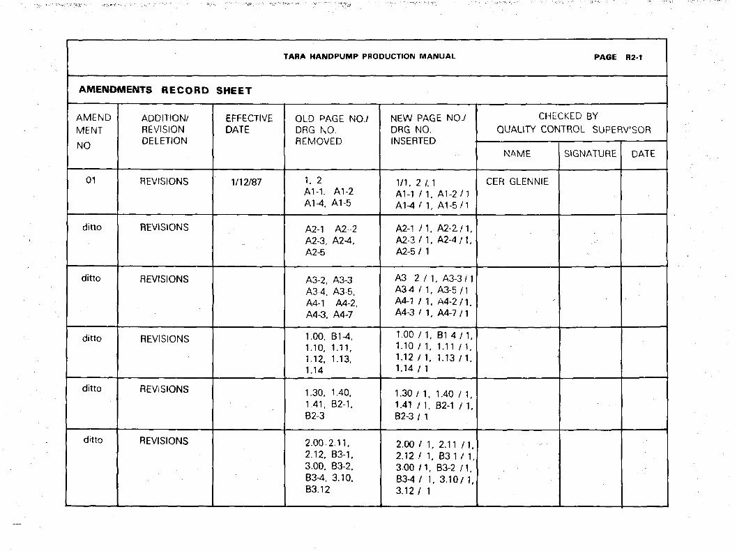
TARA HANDPUMP PRODUCTION MANUAL PAGE R2-1
AMENDMENTS RECORD SHEET
AMEND
MENT
NO
01
ditto
ditto
ditto
ditto
ditto
ADDITION/REVISIONDELETION
REVISIONS
REVISIONS
REVISIONS
REVISIONS
REVISIONS
REVISIONS
EFFECTIVEDATE
1/12/87
OLD PAGE NO./DRG NO.REMOVED
1, 2A M . A1-2A1-4, A1-5
A2-1 A2-2A2-3, A2-4,A2-5
A3-2, A3-3A3-4, A3-5,A4-1 A4-2,A4-3, A4-7
1.00, B1-4,1.10, 1.11,1.12, 1.13,1.14
1.30, 1.40,1.41, B2-1,B2-3
2.00,2.11,2.12, B3-1.3.00, B3-2,B3-4, 3.10,B3.12
NEW PAGE NO./DRG NO.INSERTED
1/1, 2 /, 1A1-1 / 1, A1-2/1A1-4/ 1, A1-5/1
A2-1 M , A2-2 /1 ,A2-3/ 1, A2-4/1 ,A2-5 / 1
A3 2 / 1 , A3-3/1A34 / 1, A3-5/1A4-1 / 1, A4-2/1,A4-3 / 1, A4-7/1
1.00 / 1, B1 4 / 1 ,1.10 / 1, 1.11 M ,1.12 / 1, 1.13 / 1 ,1.14 / 1
1.30 / 1, 1.40 / 1,1.41 / 1 , B2-1 / 1,82-3 / 1
2.00 / 1, 2.11 / I ,2.12 / 1, B3-1 / 1,3.00 n, B3-2 / I ,83-4/ 1, 3.10/ 1,3.12 / 1
CHECKED BY
QUALITY CONTROL SUPERVISOR
NAME
CER GLENNIE
SIGNATURE DATE
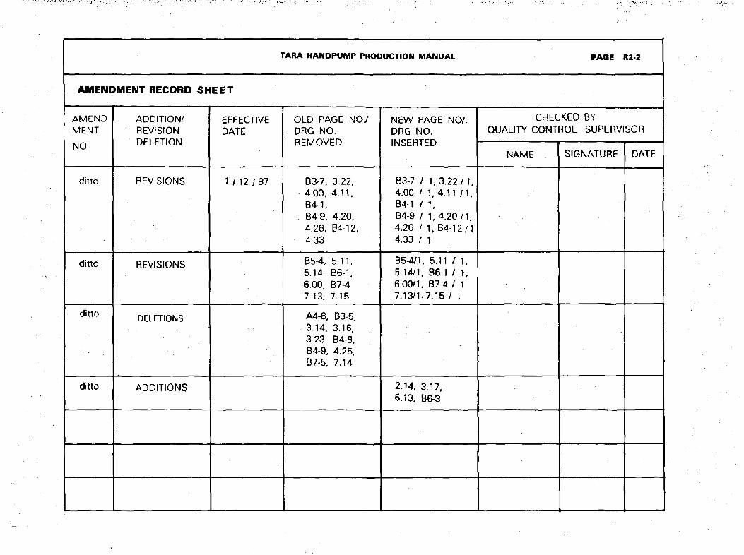
TARA HANDPUMP PRODUCTION MANUAL PAGE R2-2
AMENDMENT RECORD SHEET
AMENDMENT
NO
ditto
ditto
ditto
ditto
ADDITION/REVfSIONDELETION
REVISIONS
REVISIONS
DELETIONS
ADDITIONS
EFFECTIVEDATE
1/12 7 87
OLD PAGE NO./DRG NO.REMOVED
B3-7, 3.22,4.00, 4.11,B4-1,B4-9, 4.20,4.26, B4-12.4.33
BSA, 5.11,5.14, B6-1,6.00, B 7 ^7.13, 7.15
A4-8, B3-5,3.14, 3.16,3.23. B4-8,B4-9, 4.25,B7-5, 7.14
NEW PAGE NO/.DRG NO.INSERTED
B3-7 / 1 ,3.22/1,4.00 / 1,4.11 / 1 .B4-1 / 1,B4-9 / 1,4.20/1,4.26 / 1, B4-12/14.33 / 1
B5-4/1, 5.11 /. 1,5.14/1, B6-1 / 1,6.00/1, B7-4 / 17.13/1-7.15 / 1
2.14, 3.17,6.13, B6-3
CHECKED BYQUALITY CONTROL SUPERVISOR
NAME SIGNATURE DATE
TARA HANDPUMP PRODUCTION MANUAL PAGE R2-3
AMENDMENT RECORD SHEET
AMENDMENTNO
ADDITION/REVISIONDELETION
EFFECTIVEDATE
OLD PAGE NO./DRG NO.REMOVED
NEW PAGE NO./DRG NO.INSERTED
CHECKED BYQUALITY CONTROL SUPERVISOR
NAME SIGNATURE DATE
TARA HANDPUMP PRODUCTION MANUAL DHAKA BANGLADESH