The Synthesis of Soil Resistivity and EMF of underground ...
9
The Synthesis of Soil Resistivity and EMF of underground Cable combined with 3-D Electromagnetic Field Study in Analyzing the Grounding Touch Jeu-Min Lin Graduated Ph.D. student, Department of Electrical Engineering National Cheng Kung University Tainan, Taiwan E-mail address: [email protected] Abstract The earthing analysis is proposed in this paper. The effects of 3-D electromagnetic field and the influences of stray current are considered in the text simultaneously. The activity in the high-voltage environment is risky of being injured by electric shock. The safety of personnel in and around electric power the installations has been a prime concern. Specially, the safety is generally in terms of the allowable touch and step voltages. These voltages are related to the earthing resistance of human foot. I ofn order to increase the safety of personnel, a high resistivity surface layer of gravel is normally existed in the substation switchyards or other high voltage areas. The thickness of this layer will affect the calculation of the earthing resistance of human foot. Thus, the effect of soil resistivity will be considered in this paper. Among them, the electromagnetic field and humidity factors are also considered in this paper. As a result, the surface layer of gravel can be used to reduce the earthing resistance of human foot. The equivalent model of human foot was modeled by the circular plate conductor in the past. Which consider the beauty of the environment, most of the transmission lines are in the surface, so the transmission line generated by the discrete current will affect the earthing resistance estimation, thus the proposed paper will consider the composition of the special function which is the mathematical calculus popularized by the basic theorem of calculus. On the other hand, the damp ingredients, temperatures, and soil resistivity on the surface will also be considered in this paper. This paper research into the proposed method for estimating the earthing resistance of human foot and proposes an equivalent model for calculating the grounding resistance of human foot. The comparisons of the method are also shown in this paper. Keywords: Earthing analysis, 3-D electromagnetic field, stray current, soil resistivity, earthing, resistance estimation, attenuation element, step voltage, contact voltage, body earthing resistance, electromagnetic field elements, underground cable, and damp ingredients. I. INTRODUCTION In the high voltage environments, such as work in the substations or railway dispatching places, high voltage electric towers side, or Underground Railroad track sides, the ground surface is usually evenly covered with a layer of 8 to 25cm thickness of gravel, to increase the soil and the contact resistance between the feet (Contact Resistance). Assuming that the equivalent resistance of the shoes and socks is zero, the contact resistance is the equivalent resistance of the gravel layer. Because the contact resistance between the soil layer and the foot is large, when the accident occurs (for example, the hand touches the lightning striking device), the current flowing through the body will be much smaller than INTERNATIONAL JOURNAL OF SYSTEMS APPLICATIONS, ENGINEERING & DEVELOPMENT DOI: 10.46300/91015.2020.14.6 Volume 14, 2020 ISSN: 2074-1308 31
Transcript of The Synthesis of Soil Resistivity and EMF of underground ...
The Synthesis of Soil Resistivity and EMF of underground Cable combined with 3-D
Electromagnetic Field Study in Analyzing the Grounding Touch
Jeu-Min Lin
Graduated Ph.D. student, Department of Electrical Engineering
National Cheng Kung University
Tainan, Taiwan
E-mail address: [email protected]
AbstractThe earthing analysis is proposed in this paper. The effects of 3-D electromagnetic field and the influences of stray current
are considered in the text simultaneously. The activity in the high-voltage environment is risky of being injured by electric
shock. The safety of personnel in and around electric power the installations has been a prime concern. Specially, the safety is
generally in terms of the allowable touch and step voltages. These voltages are related to the earthing resistance of human foot.
I ofn order to increase the safety of personnel, a high resistivity surface layer of gravel is normally existed in the substation
switchyards or other high voltage areas. The thickness of this layer will affect the calculation of the earthing resistance of
human foot. Thus, the effect of soil resistivity will be considered in this paper. Among them, the electromagnetic field and
humidity factors are also considered in this paper. As a result, the surface layer of gravel can be used to reduce the earthing
resistance of human foot. The equivalent model of human foot was modeled by the circular plate conductor in the past. Which
consider the beauty of the environment, most of the transmission lines are in the surface, so the transmission line generated by
the discrete current will affect the earthing resistance estimation, thus the proposed paper will consider the composition of the
special function which is the mathematical calculus popularized by the basic theorem of calculus. On the other hand, the damp
ingredients, temperatures, and soil resistivity on the surface will also be considered in this paper. This paper research into the
proposed method for estimating the earthing resistance of human foot and proposes an equivalent model for calculating the
grounding resistance of human foot. The comparisons of the method are also shown in this paper.
Keywords: Earthing analysis, 3-D electromagnetic field, stray current, soil resistivity, earthing, resistance estimation,
attenuation element, step voltage, contact voltage, body earthing resistance, electromagnetic field elements, underground cable,
and damp ingredients.
I. INTRODUCTION
In the high voltage environments, such as work in the
substations or railway dispatching places, high voltage
electric towers side, or Underground Railroad track sides, the
ground surface is usually evenly covered with a layer of 8 to
25cm thickness of gravel, to increase the soil and the contact
resistance between the feet (Contact Resistance). Assuming
that the equivalent resistance of the shoes and socks is zero,
the contact resistance is the equivalent resistance of the
gravel layer. Because the contact resistance between the soil
layer and the foot is large, when the accident occurs (for
example, the hand touches the lightning striking device), the
current flowing through the body will be much smaller than
INTERNATIONAL JOURNAL OF SYSTEMS APPLICATIONS, ENGINEERING & DEVELOPMENT DOI: 10.46300/91015.2020.14.6 Volume 14, 2020
ISSN: 2074-1308 31
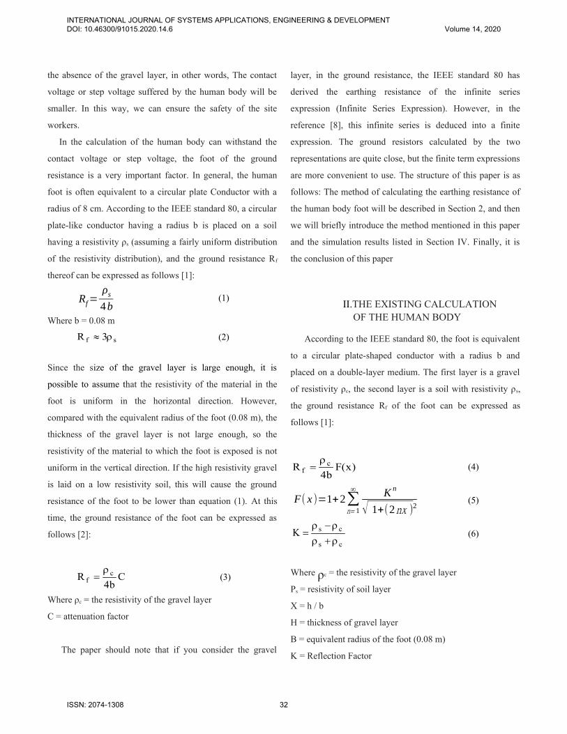
the absence of the gravel layer, in other words, The contact
voltage or step voltage suffered by the human body will be
smaller. In this way, we can ensure the safety of the site
workers.
In the calculation of the human body can withstand the
contact voltage or step voltage, the foot of the ground
resistance is a very important factor. In general, the human
foot is often equivalent to a circular plate Conductor with a
radius of 8 cm. According to the IEEE standard 80, a circular
plate-like conductor having a radius b is placed on a soil
having a resistivity ρs (assuming a fairly uniform distribution
of the resistivity distribution), and the ground resistance Rf
thereof can be expressed as follows [1]:
Rf=ρs4b
(1)
Where b = 0.08 m
sf 3R (2)
Since the size of the gravel layer is large enough, it is
possible to assume that the resistivity of the material in the
foot is uniform in the horizontal direction. However,
compared with the equivalent radius of the foot (0.08 m), the
thickness of the gravel layer is not large enough, so the
resistivity of the material to which the foot is exposed is not
uniform in the vertical direction. If the high resistivity gravel
is laid on a low resistivity soil, this will cause the ground
resistance of the foot to be lower than equation (1). At this
time, the ground resistance of the foot can be expressed as
follows [2]:
Cb4
R cf
(3)
Where ρc = the resistivity of the gravel layer
C = attenuation factor
The paper should note that if you consider the gravel
layer, in the ground resistance, the IEEE standard 80 has
derived the earthing resistance of the infinite series
expression (Infinite Series Expression). However, in the
reference [8], this infinite series is deduced into a finite
expression. The ground resistors calculated by the two
representations are quite close, but the finite term expressions
are more convenient to use. The structure of this paper is as
follows: The method of calculating the earthing resistance of
the human body foot will be described in Section 2, and then
we will briefly introduce the method mentioned in this paper
and the simulation results listed in Section IV. Finally, it is
the conclusion of this paper
II.THE EXISTING CALCULATION
OF THE HUMAN BODY
According to the IEEE standard 80, the foot is equivalent
to a circular plate-shaped conductor with a radius b and
placed on a double-layer medium. The first layer is a gravel
of resistivity ρc, the second layer is a soil with resistivity ρs,
the ground resistance Rf of the foot can be expressed as
follows [1]:
)x(Fb4
R cf
(4)
F( x )=1+2∑n= 1
∞ K n
√ 1+(2nx )2(5)
cs
csK
(6)
Where ρc = the resistivity of the gravel layer
Ρs = resistivity of soil layer
X = h / b
H = thickness of gravel layer
B = equivalent radius of the foot (0.08 m)
K = Reflection Factor
INTERNATIONAL JOURNAL OF SYSTEMS APPLICATIONS, ENGINEERING & DEVELOPMENT DOI: 10.46300/91015.2020.14.6 Volume 14, 2020
ISSN: 2074-1308 32

According to the hemispherical electrode (Hemispherical
Electrode) resistance method, and the use of virtual image
method (Method of Image) [2], can be derived equations (4),
(5) and (6). In order to simplify the complex mathematical
operations, so in the derivation of the process made some
assumptions, but this has caused the equation produced an
error. Especially when h smaller, the error will be greater [5].
As can be seen from the past figures and literatures, the slope
of the curve increases as h decreases, but when h is small, the
slope of the curve is reduced.
In another method of earthing resistance, the equivalent
model of the foot is also a circular plate conductor, but the
derivation method is different from the derivation method of
the IEEE standard 80 equation.
If the foot is equivalent to a radius of b (= 0.08m) of the
circular plate-like conductor, placed in the resistivity ρs on
the soil (assuming a fairly uniform distribution of resistivity),
the earthing resistance can be expressed as follows [1]:
b4R s
f
(7)
If the gravel layer is considered, the ground resistance can be
expressed as follows [3, 4, 5]:
)x(Hb4
R cf
(8)
1nP
41)x(H (9)
])nx2(
1
40
33
)nx2(
1
12
71[
nx2
KP
42
n
(10)
cs
csK
(11)
When (2h) / b> 3.5 or h> 0.14m, the values obtained by
Equations (8) and (9) are more accurate. Appendix A can be
referred for restrictions on this scope.
Then, the design can be synthesized with ease that
transfers the descriptions to gate-level net lists without
further effort.
III. THE PROPOSED METHOD
In this paper, Fig. 1 is a plate-like conductor is placed on
a double-layer medium, the first layer is a gravel of resistivity
ρc, and the second layer is a soil with resistivity ρs. Among
them, the gravel layer thickness h. We can use the virtual
image method we can get plate-like conductor and its mirror
(Images) position distribution. Assuming that the ground
current of the plate conductor is I, if the boundary between
the air and the gravel layer is the mapping interface, the
Current is not the same; if the boundary between the soil
layer and the gravel layer As the mapping interface, then the
current will be proportional to the power of the reflection
factor K, as shown in Fig. 2. Where K = (ρs - ρc) / (ρs + ρc).
The resistivity of all the regions in Fig. 4 is ρc [10], whether
the plate conductor itself or its mirror is discharged to the
gravel layer with resistivity ρc.
↑
↓
Fig. 1 Schematic representation of a square plate
conductor in a gravel layer
INTERNATIONAL JOURNAL OF SYSTEMS APPLICATIONS, ENGINEERING & DEVELOPMENT DOI: 10.46300/91015.2020.14.6 Volume 14, 2020
ISSN: 2074-1308 33

Fig. 2 Square plate-like mapping architecture
S N
Fig. 3 The diagram of magnetic field
Using the superposition principle (Superposition
Theorem), the average potential Vave of the plate-like
conductor can be obtained as follows, which also consider the
factors of electromagnetic field in the proposed paper. Fig. 3
shows a schematic view of the magnetic field lines displayed
through the iron powder on the white paper, which is known
that the pure quantity of the electromagnetic field function
has an important influencing factor on the creatures. On the
other hand, this paper considers the electromotive force
generated by electrostatic charge in space, so that [11]:
]d
)1(sinh
d[sinhr2V 11
p
(12)
Where r = the radius of the wire,
σ = surface charge density.
INTERNATIONAL JOURNAL OF SYSTEMS APPLICATIONS, ENGINEERING & DEVELOPMENT DOI: 10.46300/91015.2020.14.6 Volume 14, 2020
ISSN: 2074-1308 34

V ave=2 IR+ 4KIRm (2h )+4K2 IRm (4h )+⋯
=I [ 2R+ 4∑n= 1
∞
K nRm( 2 nh ) ]+ρ(13)
R fpproxρ s (14)
1
242n
nhmnave
p RKRI
VR (15)
Where R = plate-like conductor earthing resistance obtained
in a uniform medium of resistivity ρc
Rm (2nh) = mutual resistance of two parallel plate-
like conductors spaced 2nh apart in a
uniform medium of resistivity ρc
(Mutual Ground Resistance)
ρ = Volume charge density
▽ = gradient operator
D = electric flux density
.=dot operator
It was known that power system consists of two units of
active power and reactive power, and the amount of power is
the area surrounded by the active and reactive work function
on the graph. Therefore, this proposed paper has been
considered the energy which is generated by the Green's
function [13]. This function is a known vector calculus
theorem which is shown in eq. (16), to maintain the law of
conservation of energy [14].
∮ Pdx+Qdy=∫∫R
dA
(16)
Where c is a closed smooth curve on a plane and the area
around it is, supposing the function P (x, y) and Q (x, y) are
continuous and one partial derivative is continuous, the
equation holds as discussed Green’s function, and variables P
and Q exist in the R field. In other words, the Green’s
function has to be considered in eq. (13).
On the other hand, if the potential problem of electrostatic
charge in the electric field space is considered in this paper,
the potential at space satisfies Poisson's function. So equation
(13) must be reconsidered the composition of ▽2u = -ρ/ε,
which is called by Poisson’s equation [12].
Based on the previous studies, it is known that the factors of
humidity and temperature of the environment are the great
influence elements of the resistance estimation. According to
the literatures, the resistance estimation and the relationship
between humidity and temperature are exponential functions,
as shown below:
)t-β(texp)Φ-Φ(αexp 000 tRRR (17)
, where 0R = initial resistance,
0t = initial temperature,
α = humidity constant,
Φ = wetting coefficient,
0Φ = initial value of the wetting coefficient
tR = starting resistance
β = temperature constant.
Assuming that the length of the strip conductor is , the
width is a and the thickness is b, the ground resistance R of
the strip conductor in the uniform medium of the resistivity ρc
is as follows [10]:
])ba(2
aba
a
2[ln
2R
2
2c
(18)
When the width a is much larger than the thickness b and the
length is equal to the width a, the ribbon conductor can be
regarded as a square plate conductor,
cR 5966.0 (19)
INTERNATIONAL JOURNAL OF SYSTEMS APPLICATIONS, ENGINEERING & DEVELOPMENT DOI: 10.46300/91015.2020.14.6 Volume 14, 2020
ISSN: 2074-1308 35

]d
)1(sinh
d[sinhr2V 11
p
(20)
Where r = radius of the wire,
Σ = surface charge density
Fig. 4 The geometric position on the two parallel lines
As shown in Fig. 4, the two metal lines are long and spaced
apart from each other. If the surface charge distribution of the
metal line AB is uniform, the potential Vp at any point on the
wire CD can be expressed as
]d
)1(sinh
d[sinhr2V 11
p
(21)
Where r = the radius of the wire, σ = surface charge density.
The average potential Vave of the metal wire CD is :
1
0
11ave d]
d
)1(sinh
d[sinhr2V
=4πrσ(sinh−1 ℓd−√ 1+ d2ℓ2+ dℓ )
)dd
1d
(sinhQ2
2
21
(22)
Where Q = total charge of metal line AB.
Since the square plate-like conductor can be visually
composed of an infinite number of metal wires, the average
potential caused by a charged square-shaped conductor on the
other square-shaped conductor is also equation (18). So the
mutual resistance Rm(d) can be expressed as [9]:
Q
V
4C4R avecc
)d(m
)1(sinh2 2
21
dd
dc
(23)
Where ρc = the resistivity of the environment in which the
conductor is located.
Therefore, the resistance of the two-sided plate-shaped
conductor at a distance of 2nh is
Rm (2 nh )=ρc2πℓ
(sinh−1 ℓ2 nh
−√ 1+(2nh )2
ℓ2
+2 nhℓ
)
(24)
Equations (15) and (23) are substituted into Equation (13), so
that the ground resistance Rf after the equivalent of a square
plate-like conductor can be obtained as follows:
)y(S1931.1R cf
(25)
S ( y )=1+1 . 6762∑n= 1
∞
T (26)
T=K n [sinh−1 12 ny
+2 ny −√ (2ny )2+1 ]
(27)K = (ρs-ρc) / (ρs+ρc) (28)
Where ρc = the resistivity of the gravel layer,
ρs = resistivity of soil layer,
h = thickness of gravel layer,
= Side length of square plate conductor,
y = h /,
K = reflection factor
By the way in this paper, when (2h) /> 1, the values obtained
by equations (23) and (24) are more accurate.
INTERNATIONAL JOURNAL OF SYSTEMS APPLICATIONS, ENGINEERING & DEVELOPMENT DOI: 10.46300/91015.2020.14.6 Volume 14, 2020
ISSN: 2074-1308 36

If the coefficient (ρc / 4b) of equation (25) is equal to the
coefficient of equation (25) (1.1931ρc / π), = 0.1215m. In this
way, when h> 0.06m, the value obtained by equation (22) is
more accurate. Therefore, when K is equal to -0.2, -0.4, -0.6,
-0.8, the relationship between S (y) and h is shown in Fig. 5.
If ρs = 100 [Ω‧m], K is equal to 0, -0.1, -0.2,…, -0.9, the
relationship between Rf and h is shown in Fig. 6. We can see
from Fig. 5 the following described the phenomenon. When
the thickness of the gravel layer remains constant, the ground
resistance of the foot decreases as the reflection factor
increases. When the reflection factor remains constant, the
ground resistance of the foot decreases as the thickness of the
gravel layer decreases. Table 1 shows the comparison of the
respective attenuation factors. To observe these data, we find
that S (y) is quite close to H (x) and in any case F (x) is less
than H (x) and S (y). In addition, when K = 0, regardless of h
for several, the attenuation factor is 1. Since K = 0 means that
the resistivity of the soil layer is the same as that of the gravel
layer. Therefore, regardless of any of the earthing resistance
formula in this paper, the value obtained is equal with. On the
other hand, we can also find that the effect of K = 0 is exactly
the same as h = 0 and the resistivity of the soil layer is equal
to the resistivity of the gravel layer.
Fig. 5 The map of the relationships of S (y), h and K
Fig. 6 The map of the relationships of Rf and h, K relation
Table 1 A comparison table of attenuation factor
K h(cm) F(x) H(x) S(y)
0 6 1 1
0 10 1 1
0 14 1 1 1
0
0
20
24
1
1
1
1
1
1
-0.1 6 0.895033 0.924715
-0.1 10 0.929441 0.952914
-0.1 14 0.947730 0.966839 0.965953
-0.1
-0.1
20
24
0.962622
0.977524
0.976335
0.977052
0.975926
0.975981
-0.3 6 0.714517 0.793737
-0.3 10 0.806635 0.870532
-0.3 14 0.856418 0.909034 0.906141
-0.3
-0.3
20
24
0.897346
0.938271
0.934816
0.954819
0.933715
0.961718
-0.5 6 0.563943 0.682433
-0.5 10 0.702546 0.800239
IV. THE SIMULATED TESTS
INTERNATIONAL JOURNAL OF SYSTEMS APPLICATIONS, ENGINEERING & DEVELOPMENT DOI: 10.46300/91015.2020.14.6 Volume 14, 2020
ISSN: 2074-1308 37

-0.5 14 0.778711 0.859746 0.855117
-0.5
-0.5
-0.5
20
24
0.841525
0.917691
0.899416
0.939418
0.897625
0.899727
-0.7 6 0.435335 0.586038
-0.7 10 0.612433 0.738949
-0.7 14 0.711018 0.816825 0.810543
-0.7
-0.7
20
24
0.792814
0.799813
0.868511
0.908506
0.866124
0.868126
-0.9 6 0.323722 0.50097
-0.9 10 0.533029 0.684634
-0.9 14 0.651131 0.778934 0.770922
-0.9
-0.9
20
24
0.749615
0.798857
0.841116
0.872585
0.838121
0.860529
Marks: F (x) is the attenuation factor of IEEE standard 80.,H(x) is the attenuation factor of the circular plateconductor, and S(y) is the attenuation factor of the square plateconductor.
V. CONCLUSIONS
Through the discussions of this paper and the related
simulation experiments, the following conclusions can be
summarized:
(a.) If the surface covered with a layer of high resistivity
gravel, can increase the contact resistance between the soil
and feet. Because the contact between the soil layer and the
foot is very large, so when the accident occurs, the current
through the body than the absence of gravel layer is much
smaller. Therefore, covered with gravel can improve the
safety of the site staff.
(b.) When the reflection factor remains constant, the
attenuation factor decreases as the thickness of the gravel
layer decreases. On the other hand, the contact voltage or step
voltage is proportional to the ground resistance, so the
thickness of the gravel layer is thinner, the human body will
suffer the step voltage or contact voltage will be smaller. See
Appendix B for details.
(c.) When the thickness of the gravel layer remains constant,
the attenuation factor increases as the reflection factor
increases. So the greater the reflection factor, the human body
suffered by the step voltage or contact voltage will be
smaller. See Appendix C. for details.
(d.) The attenuation factor S (y) and H (x) are quite close to
each other, the error is less than 1.2%. Therefore, the
formulas presented in this paper are quite accurate compared
with those in the references. And the use range of S (y) (the
thickness of the gravel layer) is larger than that of H (x).
(e.) (Y) / F (x) in any case, the attenuation factor F (x) is less
than S (y) and H (x), especially when K <-0.9 and h <10cm,
The In addition, due to the inaccuracy of the equation in
IEEE Standard 80, the ground resistance standard set by it is
somewhat conservative compared to other literature and this
text.
(f.) With the discussions of the proposed paper, this content
can enhance and ensure the personal safety.
(g.) Based on the Kirchhoff's law, if the resistance remains
constant, the greater the voltage, the greater the current,
making the larger the electromagnetic field. In other words,
the phenomenon will affect the health of human being.
(h.) According to the medical literatures, as time changes,
high electromagnetic fields can affect the responses of
human physiology and psychology.
(i.) According to Coulomb’s Law, it is known that the
interaction between the two stationary point charges in
vacuum is inversely proportional to the square of the
distance. In other words, the impact of overhead lines or
substations is almost zero.
(j.) Known wire has resistance and inductance and
capacitance, the impedance is the sum of the resistance and
reactance in the vector, the resistance can be ignored at low
current, and the inductance can be ignored at low
INTERNATIONAL JOURNAL OF SYSTEMS APPLICATIONS, ENGINEERING & DEVELOPMENT DOI: 10.46300/91015.2020.14.6 Volume 14, 2020
ISSN: 2074-1308 38
)320
99
24
71(
4
4
2
2,
s
a
s
a
s
a
Q
aV save(B.2)
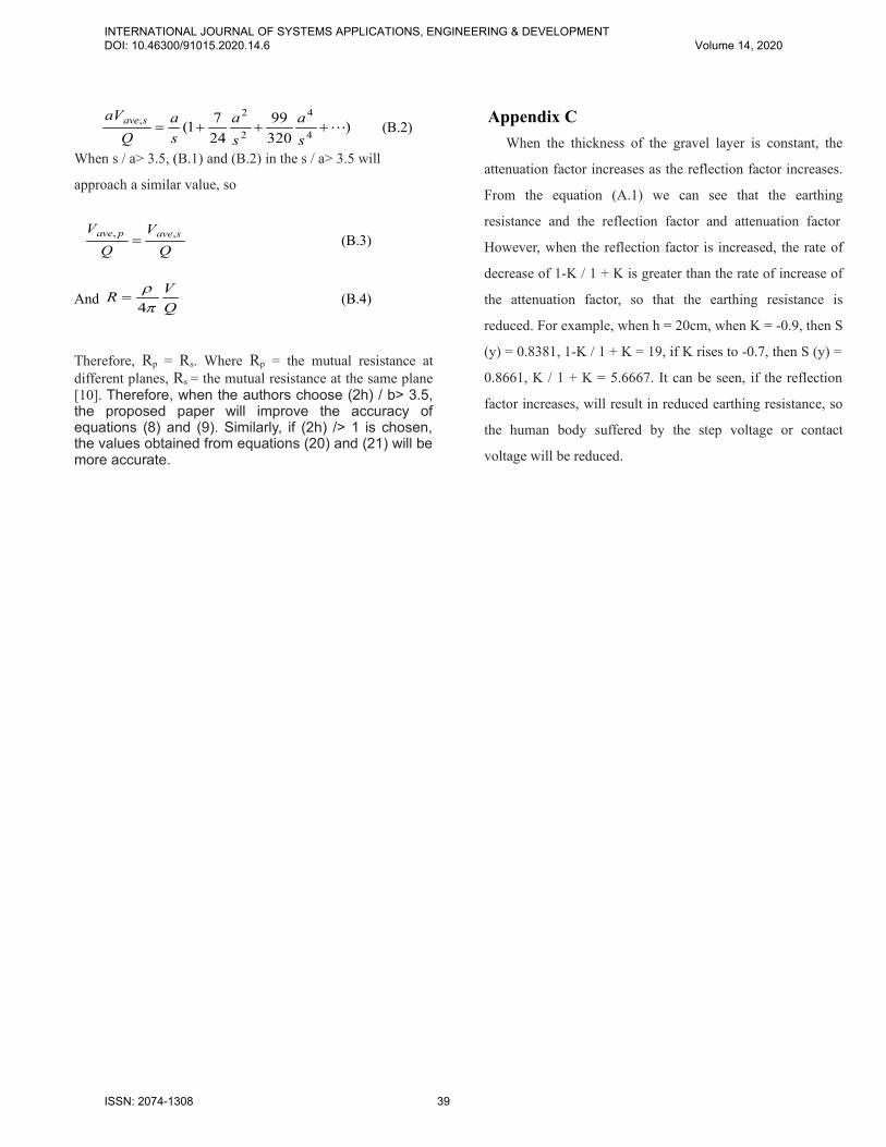
When s / a> 3.5, (B.1) and (B.2) in the s / a> 3.5 will
approach a similar value, so
Q
V
Q
V savepave ,, (B.3)
And Q
VR
4 (B.4)
Therefore, Rp = Rs. Where Rp = the mutual resistance atdifferent planes, Rs = the mutual resistance at the same plane[10]. Therefore, when the authors choose (2h) / b> 3.5,the proposed paper will improve the accuracy ofequations (8) and (9). Similarly, if (2h) /> 1 is chosen,the values obtained from equations (20) and (21) will be more accurate.
Appendix C
When the thickness of the gravel layer is constant, the
attenuation factor increases as the reflection factor increases.
From the equation (A.1) we can see that the earthing
resistance and the reflection factor and attenuation factor.However, when the reflection factor is increased, the rate of
decrease of 1-K / 1 + K is greater than the rate of increase of
the attenuation factor, so that the earthing resistance is
reduced. For example, when h = 20cm, when K = -0.9, then S
(y) = 0.8381, 1-K / 1 + K = 19, if K rises to -0.7, then S (y) =
0.8661, K / 1 + K = 5.6667. It can be seen, if the reflection
factor increases, will result in reduced earthing resistance, so
the human body suffered by the step voltage or contact
voltage will be reduced.
INTERNATIONAL JOURNAL OF SYSTEMS APPLICATIONS, ENGINEERING & DEVELOPMENT DOI: 10.46300/91015.2020.14.6 Volume 14, 2020
ISSN: 2074-1308 39