The symmetrical optical system - archive.org
114
Cambridge Tracts in Mathematics and Mathematical Physics Gkneral Editors P. HALL, F.R.S., AND F. SMITHIES, Ph.D. No. 25 THE SYMMETRICAL OPTICAL SYSTEM BY G. C. STEWARD 355 08 CAMBRIDGE UNIVERSITY PRESS
Transcript of The symmetrical optical system - archive.org

Cambridge Tracts in Mathematics
and Mathematical Physics
Gkneral Editors
P. HALL, F.R.S., AND F. SMITHIES, Ph.D.
No. 25
THE SYMMETRICALOPTICAL SYSTEM
BY
G. C. STEWARD
35508
CAMBRIDGE UNIVERSITY PRESS

/

Cambridge Tracts in Mathematics
and Mathematical Physics
General Editors
P. HALL, F.R.S. AND F. SMITHIES, Ph.D.
No. 25
THE SYMMETRICAL OPTICAL SYSTEM

BURLINGTON

THE SYMMETRICALOPTICAL SYSTEM
BY
(^6. STEWARD, Sc.D.
Professor of Mathematics in the University of Hull
' Sometime FelUnu of Oonville and Caius College, Cambridge
CAMBRIDGEAT THE UNIVERSITY PRESS
1958

ad.
^8-PUBLISHED BY
THE SYNDICS OF THE CAMBRIDGE UNIVERSITY PRESSBentley House, 200 Euston Road, London, N.W. 1
American Branch: 32 East 57th Street, New York 22, N.Y.
First printed 1928Reprinted 1 1958 /
Firat printed in Great Britain at the University Press, Cambridge
Reprinted by offset-litho by Jarrold dt Sons Ltd., Norwich

PREFACE
IN the following tract is given an outline of the theory of the Sym-
metrical Optical System, both from the purely geometrical and also
from the physical point of view. The first few chapters are based upon
a course of lectures delivered to students of mathematics and of physics
and the interest, to this extent, is theoretical ; but the methods employed
lend themselves readily to the computation of actual optical systems, and
in Chapter v are given formulae used in optical calculations : it is hoped
that these will be of practical interest. The treatment is based upon the
Characteristic Function of Hamilton or else upon one of its modifications,
the Eikonal; for, in my opinion, such a function offers by far the
most powerful method of examining the behaviour of optical systems,
whether from the theoretical or from the practical point of view. The
geometrical meaning of the various aberrations is considered, both those
of the first order and also those of higher orders, together with the more
important of the Optical Conditions such, for example, as the recent
Optical Cosine Law, of which the well-known Sine-Condition is but
a particular case. And, inasmuch as the effect of the geometrical aber-
rations is very largely masked by diffraction phenomena, an account
is given of the diffraction patterns associated with the optical system
and the modifications of them due to these geometrical aberrations;
moreover in addition to the usual circular aperture other forms of
aperture also are considered, namely, the annular aperture, the slit
aperture and the semi-circular aperture.
I am greatly indebted to Mr T. Smith, of the Optical Department of
the National Physical Laboratory, for his kindness in reading the proofs
of the tract; and I should like to record here my gratitude to him for
his kindly encouragement in optical work and for many pleasant hours
spent at the Laboratory.
I have also to render my acknowledgments to the Council of the
Royal Society for their courteous permission to reproduce several
diffraction diagrams, appearing in the last two chapters, which were
published in a Paper communicated to the Society. And, finally, it
remains for me to express my thanks to the University Press for the
usual and very high standard of their work.
G. C. S.
CAMBRIDGEDecember, 1927
<^x o §^3 /^


CONTENTSFAQE
PREFACE V
CHAP.
I. ELEMENTARY THEORY§§ 1-4. Pure Geometry 1
§§ 5, 6. Refraction at a single spherical surface ... 5
§ 7. Various formulae 8
§§ 8, 9. The general system—the ^-formulae .... 9
§ 10. The /-formulae 11
§ 11. The 'modified' notation 12
§ 12. The addition of systems 13
§ 13. The aperture stop and the field stop . . . .14§ 14. Aplanatism 15
References 16
II. THE CHARACTERISTIC FUNCTION AND THE EIKONAL
§§ 1-3. The reduced path and its properties .... 16
§ 4. The Characteristic Function 19
§§ 5-7. The Eikonal 20
§ 8, The Aberration Function 23
§ 9. Axial aberration for the pupil planes .... 24
§§ 10, 11. The Characteristic Function; the Aberration
Function 26
§ 12. Elementary properties 28
References 29
III. THE GEOMETRICAL ABERRATIONS
§ 1. General properties 30
§ 2. Change of focus 30
§ 3. The primary displacement 31
§ 4. Spherical Aberration 32
§ 5. Coma 33
§ 6. Astigmatism and Curvature of the Field.... 34
§ 7. Distortion 36
§§8-12. Aberrations of higher orders 37
§ 13. The third order aberrations 42
§ 14. The combination of aberrations 45
§ 15. Change of focus 46
§ 16. Some general remarks 47
References 49

Vlll CONTENTS
CHAP. PAGE
IV. THE SINE-CONDITION AND THE OPTICAL COSINELAW§§ 1, 2. The Sine-Condition 49
§ 3. The Cosine-Conditions 52
§ 4. Herschel's Condition 52
§ 5. Geometrical proof of the Sine-Condition .... 55
§§ 6-8. The Optical Cosine Law 57
References 61
V. THE COMPUTATION OF OPTICAL SYSTEMS
§§ 1, 2. The Focal Eikonal for a single spherical surface . . 61
§ 3. The aberration coefficients ...... 63
§ 4. The equation for the addition of aberrations ... 64
§§ 5, 6. Addition of aberration coefficients .... 65
§ 7. Formulae for aberration coefficients .... 68
§ 8. Aberrations at the principal foci 70
§ 9. Thin systems 71
References 71
VI. DIFFRACTION PATTERNS ASSOCIATED WITH THESYMMETRICAL OPTICAL SYSTEM
§§ 1-4. General formulae . 72
§ 5. The Airy disc 76
§ 6. Change of focus and spherical aberration ... 77
§ 7. The axial intensity 78
§§ 8, 9. Comatic patterns 80
§§10-12. Curvature of the field and astigmatism ... 83
§ 13. Distortion 87
References 88
VII. VARIOUS FORMS OF APERTURE
§§ 1-5. The Annular Apertiu-e 88
§§ 6-9. The Slit Aperture 94
§5^ 10-14. The Semi-circular Aperture 99
References 102

CHAPTER I
ELEMENTARY THEORY
1. Pure Geometry. In the absence of aberrations a symmetrical optical
system may be regarded as a means of transformation between two three-
dimensional regions and the transformation is such that there is a one-
to-one correspondence between points, lines and planes respectively of
the regions. Moreover to a straight line bisected normally by the axis
of the system will correspond another straight line bisected normally by
the axis, owing to the symmetry of the system.
c

ELEMENTARY THEORY
plane through F^. Similarly a point Fi and a normal plane through Fi
will correspond to the 'point at infinity' and the 'plane at infinity' in the
direction AA'.
T' P
Let SFiR and RPQ be corresponding lines; then RPQ will be parallel
to AA' since it must meet A A' 'at infinity'; and since to a normal
plane corresponds a normal plane the locus of R will be a plane normal
to the axis and intersecting it in U. Corresponding to this will be a
normal plane intersecting AA' m U' and it is clear that these same two
planes will be obtained by proceeding from the second region to the first
region. The four points T^i, F^, f/^and U' determine the transformation
completely and it is to be noticed that while 6^ and U' are corresponding
points Fi and F^ do not correspond. Let T be any point which without
loss in generality may be taken upon F^R; to find the corresponding
point draw TV parallel to AA' meeting the normal plane through ^in
V and let V be the corresponding point upon the normal plane through
U'. Let V'Fi intersect the line PQ in T'\ then T' will correspond to T.
Draw TW and T'W perpendicular to AA' ; then W and W will be
corresponding points. Moreover
F^W.W'T' = FrU.WT and W'F^ . WT= U'F^ . W'T,so that F,W.F,W'^-F,U. U'F,.
Let N and N' be two points upon the axis AA' such that FiN= JJ'F^
and FiU= N'F.^; then N and N' are corresponding points. Let any line
through N intersect the normal plane through U in Jfand let N'M' be
the corresponding line intersecting the normal plane through U' in M'.
Then UM = U'M' and NU= N' U', so that NMa,ndL N'M' are parallel.
Thus corresponding to any straight line through N there will be a
straight line through N' and these two straight lines will be parallel.
2. The transformation considered in thepreviousparagraph is uniquely
determined when F^ and F^ are given in position and also one of the
pairs of points U, U' and iV', N'\ these six points are named therefore
'cardinal points' and the normal planes through them 'cardinal planes.'

ELEMENTARY THEORY 3
Fi and i^s are called 'principal foci,' f/and U' 'unit points' and JV and
N' 'nodal' points. The following relations hold, therefore:
F,U=N'F,=/ and F^N= U'F,=/';
and /and/' are named respectively the 'first' and 'second focal lengths.'
No relation between/ and/' can be obtained from pure geometry and
recourse must be had to a law of optics which states that ' the ratio of
/to/' depends only upon the optical properties of the two regions in which
they are measured': this will be proved subsequently*.
In the figure of §1 let us write F,W = a-, FJV'^a;' a^ndW'T' = mWT,so that m is the 'magnification' or the ratio of the 'image' WT' to the
object WT; then from the relations given there we have
X - —f and X = — mf\mso that xx - -ff.
This result is due to Newton and it gives the point upon the axis in
either region corresponding to a given point upon the axis in the other
region and also the magnification associated with any pair of conjugate
points; it is seen that the origins of co-ordinates are the principal foci
and that the directions of measurement are the same.
3. Before considering formulae applicable to particular systems it maybe as well to obtain a few more general results. Thus let F^ and Fi be
the principal foci and Z/and U' the unit points of a symmetrical optical
system
and let P, P' and Q, Q' be pairs of corresponding axial points associated
respectively with magnifications m and /i; and let x, x and y, y be the
co-ordinates of these points referred to the principal foci as origins ; we
intend to change these origins to the conjugate points ^ and Q', referred
to which let the co-ordinates of P and P be u and v respectively.
Then u=^qP = F,P-F^q=f{lljn-lln)
and V = Q'F = F^P- F, Q' - -/' (m - n)
* Cf. chapter ii, § 3.

4 ELEMENTARY THEORY
from the preceding paragraph ; so that
nf'lv-flnu^l (1)
If Q and Q coincide with the unit points, « = 1, and then
riv-flu = l; (2)
if/ and/' he equal we have
lIv-lju^Mf, (3)
while if/and/' become infinite while their ratio remains finite according
to the relation
/x and fi being, so far, undefined constants, we have
fx-'/v- /j^/u = (4)
This relation is of use in 'telescopic' systems.
Again, in the general case, we may define, with Maxwell, the ratio of
P'Q' to FQ to be the 'elongation'; and we have
, ^. P'Q' F,q-F,P' {m-n)f' .,,. ,..elongation = -p^ = F^Q-F^P
^OM-l/^)/
^^^-^/-^- -^^^
The longitudinal magnification at any point upon the axis is propor-
tional therefore to the square of the transverse magnification associated
with the point; and we may find similarly the oblique magnification
corresponding to any oblique angle.
4. Again let PThQ any line through P, intersecting the first unit
plane in 7" and cutting the axis at an angle </'; let P'T' be the corre-
sponding line intersecting the second unit plane at T' and cutting the
axis at an angle \p'. Then UT= U'T and
.-. Pf^tan^ = P'i7'tanf,
i.e., /(l jtani/' = -/'(l -7w)tani/'',
." . /tan i/' =mf tan i/'',
i.e., tan i/^/tan i//' = mflf* (1)
If I and /' be the lengths of two corresponding normal lines at P and
P' we have I' = ml and then (2) takes the form
//tan 1/^ = //' tan ft, (2)
* This ratio is named, by Southall, the 'Angular Magnification' or 'Convergence-
Katie'
f Attributed to various writers, e.g., Helmholtz, Lagrange; but it appears in
Robert Smith's Compleat Opticks, Cambridge, 1738, for a system of thin lenses.

ELEMENTARY THEORY 5
i.e., this quantity is unaltered by the transformation. If the angles in-
volved be small we have
or ixlf^fxTif/' (3)
if we assume that ///*=/'//><'.
yi

6 ELEMENTARY THEORY
tract that light is propagated under the form of a wave motion and that
the disturbance originating at a point of a homogeneous medium is to
be found at a subsequent time upon a concentric sphere—the radius of
the sphere being proportional to the time interval and depending also
upon the nature of the medium.
Let P be a point upon a spherical wave-front which touches at A the
spherical boundary, centre C, between two media B and B'; let a normal
at P to the wave surface cut A C produced in Q and let the angle PQAbe small; let this normal cut the bounding surface in S and draw NPand 31S normal to ^ intersecting AC in N andM respectively. After
time t the disturbance from P will have reached S and that from A will
have reached L, upon AC; draw the sphere with centre on ^C and
passing through L and S. It will be shewn that to the first approximation
this sphere is the new wave-front.
Let U and B be the curvatures of the incident wave-front and of the
bounding surface respectively, so that
U^llAQ and B^l/AC
Then if NP = y we have
2AN=fU and 2AM=tfB;
this is an approximation and assumes that NP = 3IS. Now the distance
travelled by the light from P to the sphere is, to the same degree of
approximation, N3I,
i.e., A3I-AN = lf-{R-U).
If V be the velocity of the luminous disturbance in the medium B,
2vt = y^{B-U);

ELEMENTARY THEORY 7
and similarly if v be the velocity in the medium B' and Fthe curvature
of the symmetrical sphere through L and >S',
Tl-- I-ITV'-^^^^ (1)
and this relation does not involve y ; thus given ft, /<.', R and U there
is a unique value of F, independent of t and y, i.e., of the point chosen
upon the original wave-front. The symmetrical sphere through L and 8is therefore the new wave-front in the medium B'
.
The quantities /iC/" and ft F may be named the 'equivalent' curvatures
and (1) takes the form
l^V-ti.U={ix'-ti)B (2)
or £^{fi.U) = {t^'-fx)R=K{&2,y), (3)
where A is the usual operator of difiference. Thus the eflfect of the
refraction is to increase the equivalent curvature of the incident wave-
front by the constant quantity (/*' - ft)^ or k and this quantity depends
only upon the properties of the media and the curvature of the bounding
surface between them; it may therefore be named the 'power' of this
Moreover^^SQ^ CQ Sq ^ R-U_ ^'
Moreover^.^ ^^^, ^q- (jq j^_y ^
,
i.e., ft' sin (7/^^ = ft sin C^^,
to the degree of approximation contemplated.
6. If Q' be the centre of the new wave-front it will be seen that
between the points Q and Q' there is a one-to-one correspondence;
moreover the line of propagation PS of the incident disturbance has
been transformed into the new line SQ' of propagation of the disturbance;
we may employ therefore the geometrical transformation considered in
the previous paragraphs. It will be observed that the results obtained
are legitimate only if we neglect small quantities ; the transformation
given therefore is true only as a first approximation and in order to allow
for this we must consider the 'aberrations' of the optical system—which
accordingly will be effected in subsequent chapters.
A special case of §5 arises when the incident disturbance is reflected
at the bounding surface AS—a^ indeed will always be the case partially.
But here we may write ft' = - ft and remember that the disturbance is
to be regarded as travelling positivelyafter incidence in the direction CA
.
From (1) §5 we have fx'v'-ixv,
so that ft is a constant of the medium—varying indeed inversely as the

8 ELEMENTARY THEORY
velocity of the luminous disturbance in the medium; and it may be made
definite by writing
fx'v' = IJ.V = Vq, (1)
where v^ is the velocity of light in vacuo.
A particularly simple application of (3) §5 may be considered. Consider
two spherical surfaces placed close together and touching at A and let
the medium between them be defined by the constant fx.—the outer media
being the same and defined by the constant unity. Then a double applica-
tion of (3) § 5 and an obvious notation leads to
ft Fj = Ui + Ki and Fa = ft f/g + '^2
;
where k^ and k^ are the powers of the surfaces. But Fj = U^ since the
surfaces touch and therefore
F2 = ?7i + Kj + Kj
.
Thus the effect of a 'thin lens' is merely to make a constant addition to
the curvature of the incident wave-front.
7. Various Formulae. The formulae (2) and (3) § 5 are the funda-
mental formulae for refraction at a single spherical surface; we maynotice some other forms of these however which will be of use subse-
quently. In the first place we may change the origin of co-ordinates from
the pole A to the centre of curvature G; and it is easily verified that
the result is
1 1_^ ^'
~^
R
ix'CQ' fj.CQ fifi'
= —,=/. (1)
Here J, defined by the last relation, may be named the 'modified power'
of the surface; further the expression fxCQ will be called the 'reduced'
distance CQ, i.e., it is the geometrical distance multiplied by the con-
stant ft of the medium in which the distance is measured. The physical
meaning of this product will be examined subsequently; (1) now becomes
CQ' CQ ' ^ '
if we agree to regard all distances as reduced. Here the constant ft does
not appear explicitly and this will be found to be true generally if the
modified power be used instead of the ordinary power.
Again formulae involving angles are frequently of use and (2) §5 may
be modified to this end. Thus if SQ and SQ' cut the axis ^Q^' at angles
a and a respectively (fig. §5) we have
y = a.AQ and y = a .AQ' approximately.

ELEMENTARY THEORY
Substituting we have
I.e. A (^a) = Ky. .
.(3)
•(4)
8. The General System—the K-Formulae. The symmetrical optical
systemwill be composed, in general, of coaxial spherical surfaces sepa-
rating various media ; let us consider the optical properties of such a
system.
I
- P A„
/^n-i
Let n coaxial spherical surfaces, 1, ...n, separate media whose optical
constants are /ao? • • • /^n and let k^, ... f„ be the powers of the surfaces ; let
^1, ... ^„ be the poles of the surfaces, i.e., the points of intersection with
the axis of the system. Let a ray inclined at an angle a^ with the axis in
the first medium meet the first surface in a point at distance yi from the
axis; for the corresponding ray in the second medium let these quantities
be aj and y^ respectively; and so on. Let P be the intersection of the
ray a,, with the axis, Pi that of the ray a^, and so on; let the separations
of the surfaces be ti, t^, ... tn-i so that, e.g., AiAz^^t^. Then we have
the following relations;
3/i=^iP.ao,
which may be written
yr = Ufi.^a„,
where u(=AiP/fj^o) is the 'equivalent' distance AP and aKi*-\- tx =0.
From this it is evident that fi^aj/j-oa^ is the numerator of the 2Ath
convergent to the continued fraction
_ 1 1 1 1 .,,u + - -
,
- -, (1)Ki - «! + Kj - . . . + /C„

10 ELEMENTARY THEORY
while yxlih^-o is the numerator of the (2A.-l)th convergent to this
continued fraction. We may denote by Ki^n the numerator to the last
convergent to the continued fraction111 1Ki — — .
ai + Ki — Oa + • • • + '*»
Then we have the relation
^^ = «^,„ + ^-^ (2)
If a,j=0, P will coincide with the first principal focus F^; so that from (2)
^^^^=#^^"' ^3)
and similarly, by starting from the other end of the system,
A,F, = -p^^-^ (4)
Again P will coincide with the first nodal point if a-Q-a^; so that
from (2)
tin _ AiN ^ ^9Zi,„.
whence FiN= ^^ =/', the second focal length ; (5)
similarly the first focal length is given by
/=#- (6)
We verify therefore the general relation
/'K=//Mo* (7)
9. The quantities Ki^\ and ^"^are of importance from the point of
view of subsequent aberration theory ; and the following relations are given
from which they can be calculated step by step. Let pi be the numerator
of the last convergent to the continued fraction
111 1Kj — — —
;
Ofl + Kg - a2 + ... +Kf,
thenpi = Ki^x, and
^i,\ = i^kPi-i +Pi-2, so that pi-i =—^ ;
thus Z-,.x=Zx.x-, + K,^^ (1)
^^^ 1;^= a^— -«*-^^-^- ^2)
Chap. 11, §3.

ELEMENTARY THEORY 11
Similarly, starting from the other end of the system, we have
From these three results the quantities Ki x. and .^'^
, which are needed
in optical computation, may be calculated readily step by step. Moreover
from the above continued fraction it follows, by the elementary theory
of continued fractions, that
a result due to Gauss; and further, using the fraction of the preceding
paragraph,
UvKi^n + U-^^ +'V~^-^+ r-^ =0, (5)
where v is the equivalent distance of the conjugate point from the last
surface of the system.
Again from (1) §8
— = —5 r = -^—5 » z , \0)
if M -»- 00 ; thus a ray parallel to the axis and incident at a height 1/1
upon the first surface will intersect the surface A. at a height given by (6).
From § 6 it is evident that we may replace our refracting surfaces
by thin lenses and the results of § 8 will be similar in form; so that for
example the combined power of two thin lenses kj and ^2 at a distance
a apart is
If therefore a exceed the combined focal lengths of the thin lenses, i.e., if
the distance be positive between the second focus of the first lens and the
first focus of the second, it follows that K will be negative, assuming »ci
and K2 to be positive ; a remark the bearing of which will be evident
later.
10. The J-Formulae. From the definition in § 7 of the modified power
it is evident that corresponding to the preceding results involving the
ordinary power k there will be similar results involving the modified
power J. In the figure of § 5 let h and h' be the perpendicular distances
from the centre C upon SQ and SQ' ; then
h = CSsin CSQ and h' = CS sin CSQ';
so that fik = fji'h' = b , (1)
i.e., the quantity fj.h is unaltered by refraction. Moreover
CQ.a = h and CQ'.a^h';

12 ELEMENTARY THEORY
and also for two consecutive surfaces
^-^2 = aia,, (2)
where ai is the reduced distance between their centres of curvature. Using
therefore (2) § 7, and remembering that all distances are now reduced,
we have for a coaxial system
Oi/tto- 1 = /ib'i/ao,
'^2- ^i=-«,«i/ao,
ajao — a„_i/ao = J'„ —
,
and these axe formally the same as those of § 8. Thus we may define the
modified power J^n as the numerator of the last convergent to the
continued fraction
J.-- - -aj + Js - ••• +«/n'
and we have the relations
oJk <jJk vJx-i
T — T J. T ^"^^ " ^•A,7t ^^A+i,n J
•^ A,n. ~ «'A+i,TC + «/A -r~7 , - y- —or <^A«/A+i,ti'f'./A O./a f'^A + i
Moreover the (reduced) distances of the principal foci from the initial
and final centres of curvature are given by
*F,C, =^^-^ and a,F, =^^^',
and also F-^N= N'F^ = l/Ji^n- Again for an incident ray parallel to the
axis of the system it may be shewn that — i.'^ is proportional to the
perpendicular upon the ray in medium X from the centre of curvature
of surface A.
11. The 'Modified' notation. It will be seen from § 8 that if the systemn
be 'thin,' i.e., ^a = for all values of X, then Zi.„ = 2 kx; while if theA = l
system be formed of concentric surfaces, i.e., ax=0 for all values of A., thenn
Ji,n= 2 J^. Thus the K-formulae are adapted for thin systems and
the y^formulae for concentric systems. But further, the /A-constants of the
* A reduced distance regarded as being in the medium yu^.

ELEMENTARY THEORY 13
media do not appear explicitly if J^formulae be used ; thus Newton's
formula § 2 may be written
««' = -ff' = r^— ,
1I.e., a:x = - -j^— ,
if reduced values of w and ^' be used; or we may write
XX' = -1, (1)
where JC(= xJ^^n) and JC' (=x'Ji^n) are named 'modified reduced
distances.' Also we have Jr=- and JC' = -m: but here m is themreduced magnification, i.e., the ratio of the reduced size of the image to
the reduced size of the object. These properties of the J^formulae will
be found of considerable use subsequently.
12. Addition of Systems. Two symmetrical optical systems upon the
same axis may be regarded as one system and simple formulae may be
found to give the combined power in terms of the separate powers.
F
Ji K J,^^
Let Fi and F2, F^ and F-^ be the principal foci of the two coaxial
systems of modified powers J^ and J^ respectively ; let F and F' be the
principal foci of the combined system and J its power. Then F and l\
'
are corresponding points for the first system so that
F,F.F,F,' = -j^„
all distances being reduced. Similarly considering the points F^ and F'
for the second system we have
F^' F2.F2'F' = -j-^;
and from the points F^ and F^' and the combined system
FF,.F'F,' = -j,.
Whence
F^F^ = ±J\JJ^, F'F.: = ±J,IJJ and F,F^±J,IJJ^.
The ambiguity in sign may be cleared up by considering a special case
;
thus consider the addition of two thin lenses of positive power, the
distance between them being greater than the sum of their focal lengths,

14 ELEMENTARY THEORY
SO that F^Fx is positive here. The combined power is negative (§ 9), so
that the negative sign must be chosen in the first result above, i.e., we
have
F^F,'^-JIJxJ„ F'F^ = ^Jx\JJ and F.F^ + J^jJJ,. ...(1)
13. The Aperture Stoj) and the Field Stop. The light passing through
a symmetrical optical system is limited by the sizes of the refracting
surfaces and also, in general, by diaphragms ; which usually are circular
with their centres upon the axis of the system. Let Ai, A^, ... be the
refracting surfaces of a symmetrical system of which AA' is axis; let
PQR be an object normal to A A'. Let S be any diaphragm or 'stop' of
the system, including, as special cases, the rims of the refracting surfaces
;
then S divides the optical system into two parts—the one to the left of
S and the other to the right of S. Let S' be the image of S in the part
of the system to the left ; we may treat each stop of the system in this
As
way and accordingly we shall have a number of images such as *S", from
which we may choose that one, a', which subtends the least angle, 20,
at the axial point of the object. This image a' is said to be the
'entrance-pupil' of the optical system, while the corresponding real stop
a is named the 'aperture' stop ; similarly there will be an image a", given
by the right-hand part of the system, and this image is known as the
'exit-pupil.' It is seen that © is the semi-vertical angle of the largest
cone of rays, emanating from Q, which can pass through the system
;
accordingly is known as the 'aperture angle.' Any ray leaving Qin a direction which makes an angle with the axis greater than will be
unable to pass through the system.
Again from the various images S' , formed by the left-hand parts of
the optical system, we may choose that one, M', which subtends the
smallest angle, 2$, at the axial point of the entrance-pupil; and this
image is said to be the ' entrance-window,' while the corresponding real

ELEMENTARY THEORY 15
stop, M, is named the 'field' stop. Similarly there will be an image, M",
on the right-hand side, known as the 'exit-window'; but of course all
these names may be interchanged if we regard the light as travelling in
the opposite direction. The least angle, 4>, defined by the entrance-window
is known as the 'angular field of view' of the system; and it is clear
that the function of the field stop is to limit the extent of the object,
reproduced in the image by pencils, whose central ray passes through
the axial point of the entrance-pupil ; while the aperture stop limits
the rays passing through the system. Moreover the precise stop which
acts as field stop or as aperture stop of the system depends upon the
position of the object.
If a small luminous object be placed, normal to the axis, at Q the
energy passing from this object through the entrance-pupil, and, in
consequence, through the system, is not proportional to the aperture
angle ; for the intensity of radiation in any direction from Q will depend
upon that direction. And, in fact, the energy passing through the
system may be shewn to be proportional to the square of the quantity
ft sin®, /A being the optical index of the object space. This quantity
II sin © is known as the ' Numerical Aperture'* of the system, and plays
a very important part in the theory of the microscope.
14. Aplanatism. Let there be a sphere of radius r and centre C of a
medium of index ju. where f<-> 1; let CP'P be a diameter of the sphere
and let GP - r/j. and CP' = r/fi.
Then P and P' are inverse points with respect to the sphere and if
Q be any point upon the surface
sin CQP _sinCQP''^' ^^
and this without any approximation ; so that ani/ ray converging to Pwill, after falling upon the spherical surface, converge to P'. Moreover
sin CPQ 1 . .^.• /yD^ = - = const (2)sm CP Q fx
^
* See E. Abbe, 'On the Estimation of Aperture in the Microscope,' Joum. Roy.
Micr. Soc. (2) i (1881), pp. 388-423.

16 THE CHARACTERISTIC FUNCTION AND THE EIKONAL
Two pointsP andP ' are said to be ' aplanatic 'when both these conditions
are satisfied, i.e., when rays incident towards either pass accurately after
refraction through the other and when in addition the 'sine-condition' (2)
is satisfied. The meaning of this latter condition will be discussed later
;
here it is sufficient to say that it ensures an accurate point image of a.
point object slightly removed laterally from P.
Now if the 'sine-condition' (2) is to be satisfied we must have
QP/QP' = const., (3)
and from this it follows that the only single surface at which aplanatic
refraction is possible is the sphere. We may indeed have an accurate
point to point correspondence over any angle by using the surface of
revolution generated by a Cartesian oval ; but the sine-condition will
not be satisfied and the refraction therefore is not aplanatic. Indeed
considerable aberrations are introduced by refraction at such a surface.
REFERENCES
Czapski. Die Theorie der Optischen Instrumente nach Abbe.
Maxwell. On the General Laws of Optical Instruments. Set. Papers, vol. I,
pp. 271-285.
Southall, J. P. C. Oeometrical Optics, chs. vi, vii, xiv.
Wandersleb. Die Theorie der Optischen Instrumente nach Abbe (ed. by M. von
Rohr).
CHAPTER II
THE CHARACTERISTIC FUNCTION AND THE EIKONAL
1. TheReducedPath and itsProperties. The idea of 'reduced' distance
has been introduced in the preceding chapter and it has been defined as
the product of the geometrical distance between two points and the
index of the medium between the points. Thus to a geometrical distance
X measured in a medium of index ^u. the corresponding reduced distance
is IX.X; but this assumes that the medium is uniform. For a heterogeneous
medium the generalisation is clearly given by jfj^ds, where ds is an
element of the path between the limits of integration and /* is the index
of the medium in which the element is measured. If the medium be
uniform this clearly leads to the previous result. Thus the reduced
distance, V, from a point P to a point P' is given by
= / fji.ds.

THE CHARACTERISTIC FUNCTION AND THE EIKONAL 17
Now from Chapter i, § 6, we have seen that the index of a medium is
inversely proportional to the velocity of propagation of the luminous
disturbance in that medium ; whence it follows that the reduced distance,
V, is proportional to the time taken by the disturbance to travel from
the point P to the point P'. It is also proportional to the number of
optical 'vibrations' between the two points, i.e., to the number of wave-
lengths of the periodic disturbance.
P P'
Let now a disturbance travel from a pointP to a point P' by the path
PQP', i.e., this path is at each point normal to the wave surface of the
disturbance passing through that point. Then all the laws of geometrical
optics are contained in the statement, due to Fermat, that the path
PQP' is such that the time of propagation along it is stationary, i.e.,
for small variations of PQP'] or that the number of wave-lengths
contained in it is stationary. These quantities may be either maxima
or minima; the complete statement is
rP'
S / ixds^O, (1)
the variation sign denoting a variation of the path PQP'. It may be
verified quite readily that this leads to the usual laws of reflection and
refraction of light ; and by means of the Calculus of Variations we can
obtain from it the differential equations of the path of the luminous
disturbance in any medium in which /j. is known at every point.
2. We assume that light is propagated under the form of a wave
motion so that there will be wave surfaces or surfaces at every point of
which the medium of propagation is in the same phase of disturbance
;
and the disturbance at every point will be travelling along the normal
to the wave surface through that point. These normals in a homo-
geneous medium are, therefore, the paths of the luminous disturbance
and take the place of the 'rays' previously considered. Now upon each
normal there will be two points which are the centres of curvature of the
two principal sections of the wave surface passing through that normal,
and the locus of these points will be the surface of centres or caustic
surface ; so that each ray or normal touches the corresponding caustic
in two points. We have seen that for any two points P and Q
'j\ds = 0, (1)

18 THE CHARACTERISTIC FUNCTION AND THE EIKONAL
the path of integration being along the ray connecting these points ; if
however P and Q be upon corresponding caustic surfaces, then
^i fjids = 0, (2)
while in the particular case in which P and Q are cusps of these surfaces
h^j^ fxds = (3)
Ifwe had perfect correspondence so that thewave surfaces were concentric
spheres with centres at P and Q, then
}
fi-ds = const,/:
i.e., the reduced path is the same for all rays connecting P and Q. The
result (1) is equivalent to the statement that the variation of the reduced
path from P to Q depends, to the first order of small quantities, only
upon the displacements of P and Q themselves.
3. By an application* of the reduced path the relation between the
two focal lengths of a symmetrical system may be proved—as fore-
shadowed in § 2 of the preceding chapter.
THE CHARACTERISTIC FUNCTION AND THE EIKONAL
SO that equating these results
19
flt^=f'lt^'- •(2)
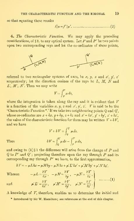
4. The Characteristic Function. We may apply the preceding
considerations, of" § 1, to any optical system. LetP and P' be two points
upon two corresponding rays and let the co-ordinates of these points,
\Q'
referred to two rectangular systems of axes, be x, y, z and x, y, z
respectively; let the direction cosines of the rays be L, M, N and
L', M', N'. Then we may write
rP'
=j
fids,
where the integration is taken along the ray and it is evident that Vis a function of the variables x, y, z and x', y', z . V is said to be the
'Characteristic Function*.' If we take two neighbouring points Q and Q',
whose co-ordinates are x + 8x, y + Sy, z + Sz and x' + Sx', y + Sy, z -i- 82;',
the value of the characteristic function for them may be written F-i- S F,
and we have
V^IV
Thus 8F =
=j iJ-ds.
JQ
fQ' fl
Ifids— \
JQ JPfids,
and owing to (1)§ 1 the difiference will arise from the change of P and
Q to P' and Q';projecting therefore upon the ray through P and its
corresponding ray through P' we have, to the first approximation,
BV=-tiL8x- fiMhy -fiN8z + fi'L'Sx + fi'M'By' + fx'N'hz.
Whence -fiL=^—, -tiM=-^,ex oy
and
AT S^ '
•(1)
A knowledge of F, therefore, enables us to determine the initial and
* Introduced by Sir W. Hamilton ; see references at the end of this chapter.

20 THE CHARACTERISTIC FUNCTION AND THE EIKONAL
final directions of a ray passing through two given points. Moreover Vsatisfies the differential equations
'^-ly-^
aF\2
C^)If the optical system be symmetrical we shall find it convenient to
restrict the movements of P and P' to planes normal to the axis of
symmetry and then if this be taken as the x and x' axis in the two spaces
we have only the final four relations of (1). It is evident that the
transformation effected by the optical system is completely determined
when the form of V is known, so that this function sums up in itself the
properties of the system ; and here F is a function of the four variables
y, z, y and z!
.
5. The Eikonal. Let -4^' be the axis of a symmetrical system and
let P and P' be two points upon corresponding rays; draw normal
planes through P and P' intersecting ^^' in and 0' respectively
—
which may conveniently be taken as origins of co-ordinates : let AA' be
the axis of x and of x and take parallel rectangular axes in the two
spaces. Let the co-ordinates of P and P' be y, z rnd y, z respectively
and write rpi
V=j f^ds
as usual ; then F is a function of the four variables y, z, y and z' . Let Qand Q' be the feet of perpendiculars from and 0' upon the ray. Wemay write |-q'
E^ ixds,Jq
and then ^is known as the 'Eikonal*.' Moreover we have
E=V^ix{My^Nz)-ti'{M'y' + N'z'), (1)
* The name 'Eikonal' was introduced by Bruns; see references. But the function
appears much earlier in Hamilton's paper, Theory of Systems of Rays.

THE CHARACTERISTIC FUNCTION AND THE EIKONAL 21
by projection of OP and O'P' upon the two portions of the ray; where
L, M, N and L', M', N' are the direction cosines of the ray in the two
spaces. By variation of (1) we have
^E=hV+tJi (M8y+i/SM+ Nhz + zhN) -/ (3/'8y +y81/' + ]V'8z' + z'SN')
= H1/8M+ fMzSN- fxly'^M' - ix'zhN'
from (1) §(4), since Fis a function oi y, z, y and s';
^E dE \
, , dE , , BEand -f'^=W" '''^^WThus we may regard E as & function of 31, iV, 31' and N' alone and
the properties of the system are completely known when the form of
this function is known.
We may define also other functions as follows:
fP' fQ'Ei= I fjids and E-,= / fids,
J Q J P
and then by similar variations we obtain the relations
^Ei dEi , , r, dEi 1 , T.7-, dEi
and -M/=^, -'^^^-a^' -'^y^W ^^^ -^^^aF"Any of these functions may be used to investigate the properties of the
optical system.
6. In the first place let us consider more fully the Eikonal function
and writerO'
'= fids,Jo
where the integration is taken along the axis of the system. Further
let U be defined by the relation
U=J(E-e),
where J is the modified power of the system; then using the relations of
§11, Chapter i, we have
and Z7 is known as the 'modified eikonal' or the 'eikonal expressed as
a ratio.' It has the advantage that the 'size' of the system is eliminated,

22 THE CHAEACTERISTIC FUNCTION AND THE EIKONAL
as also the explicit appearance of the optical indices ofthe various media.
From (1) U is a function of the four variables M, N, M' and N\ but
owing to the symmetry of the system three variables only are sufficient,
viz., a = BP+N\ b^MM' + NN' and c^M'^+N'\ ...(2)
We may therefore consider f/" as a function of these three variables a,
h and c.
The base points chosen, 0, 0', may be any points whatever ; in general
we shall take them to be corresponding points, but one other case of
considerable practical importance arises, viz., when they are the prin-
cipal foci of the system. Then U is known as the 'focal reduced eikonal'
and will be investigated later.
Let the base points chosen be corresponding points associated with a
reduced magnification m', then if there were perfect definition over the
two normal planes through and 0', associated with magnification m,
we should have the relations
Y'-mY=0 and Z'-mZ=0,
for all values of the variables.
This suggests the use of the variables M-mM' and N— mN'; in
conformity with (2) above we choose three variables a, /3 and y given in
terms of a, b and c by the relations
a {s-nif = (31- sMJ- + (N- sNJ =a-2sb + s^c, \
/3(s-mf= (M- sM') (31-mM') + (N-sN') (N-mN')^a-(s+m)b + smc, I
y (s-mf = (IT- mM'f + (1^- mNJ = a- 2mb + m% J
(3)
and owing to these linear relations IT may be considered as a function
of a, f3 and y. Here s may be considered an arbitrary constant but it will
be convenient to take it as the magnification associated with the axial
points of the pupil planes ; in any case it may be taken to be a magnifi-
cation and we can draw the normal planes through the corresponding
points which it defines upon the axis of the optical system. From
Chapter i, §11, it is seen that s-m is the distance in the image space
between the points upon the axis defined by the magnifications s and m,
i.e., the distance between the exit-pupil and the image plane. The
factor (s - mf is then added to the left-hand side of (3) for convenience
in subsequent transformations.

THE CHARACTERISTIC FUNCTION AND THE EIKONAL 23
7. From the relations (1) and (3) of §6 we have
(s-mrY' =-(s-mr^,
~ ^^ ^> \ da dM'"^
d(i dM'"^
ay dM']
and similarly
(s-myY=(s-my^^
By subtraction
(5-m)(F'-wzF) = 2(itf-si»/')^g^+(3f-mi)f')^.
Similarly
{s-m)liZ'-mZ)=2(N-sN')~ + iN-mN'f~....(l)
Now for perfect definition
Y'-mY = and Z'-twZ-Ofor all values of F and Z; thus either
for every ray ; or
'^=«-df=» (^)
M-sM' M-mM' ,
which implies that -v^, = ^^^ (3)
This latter condition implies that all rays lie in a plane through the axis
of the optical system ; which clearly is not true. We are led back to the
relation (2) and it follows that for perfect definition over the conjugate
planes associated with magnification m, U must depend only upon the
function y, i.e., we may write
U=f{y) (4)
8. The Aberration Function. In general there will not be perfect
definition over the planes associated with magnification m; in Chapter i
we saw that we were obliged to approximate to obtain the point-to-point
geometrical correspondence with which we started. It follows that U will
contain terms involving the variables a and j8 of § 6. Let us write
U=u-^, (1)

24 THE CHARACTERISTIC FUNCTION AND THE EIKONAL
where u contains only the variable y, so that u -/(y). ^ consists of any
other terms which may appear in the reduced eikonal, so that the
existence of 4> implies the presence of aberrations and $ = only in a
'perfect' system, i.e., a system giving perfect definition over the con-
jugate planes at paraxial magnification m. For this reason $ is called
the 'Aberration Function.' It may be added that the negative sign is
attached to $ for subsequent formal simplicity; moreover -$ corresponds
with a function + * associated with the Characteristic Function.
Now Y'-mY=-(^ + mQiu-^) = (^^,+mQ^,
since the operator considered annihilates any function of y only; thus
^ -'^^=m''-'^m ^^^ ^ -^^^aF'-'^al^'-^^^
and this exemplifies the fact that <E> gives completely the 'aberration'
or wandering of the ray from ideal imagery.
We have written u-/(y) and so far the form of the function is
arbitrary; it may therefore be determined to satisfy certain other con-
ditions and this accordingly is considered below. <l> is a function of a,
;8 and y in general and we may write
Tl = 2
where ^„ is homogeneous and of degree n in the variables a, /? and y, since
the aberrations are essentially of higher order than the first; to the first
approximation we shall have ideal imagery. We are introduced here to the
idea of 'orders of aberration'—which will be investigated more fully in
the sequel.
9. Axial Aberration for the Pupil Planes. We have been considering
the pair of points upon the axis defined by the magnification s and it is
only as a first approximation that we may assume that corresponding
to rays through one of these points there will be rays passing through the
corresponding point. But we proceed to shew that the form of the
function/ (y) may be determined so that this is true accurately.
Let Ug be the reduced eikonal, the axial points of the pupil planes
being base points associated with reduced magnification s; then
Us = u^'-^iI^-^)-i^-^^)iL'-l), (1)
assuming the system corrected for magnification m.

THE CHARACTERISTIC FUNCTION AND THE EIKONAL 25
The points y, z and y , z of intersection of the ray with the pupil
planes are given by
y~dM~ (s-mf dy sm L'[
,_ dU, _ 2m{M-mM') du , M' \^^
y ~ dM'~ {s-mf dy ^^ ^^U^ J
together with two similar equations for z and z'. If these co-ordinates
are to vanish simultaneously, and the pupil planes be free from axial
aberration, we must have
M 2sm (M-mM') du _ sM'L~ {s-mf dy~~ir ^^'
, . ., , N 2sm {N- mN') du sN'and similarly -^ = j r^ ^ = -tt\ (4)•^ L (s-mf dy L ' ^ -'
so that 2m{sL-'mL')j-^{s-my (5)
Squaring and adding equations (3) and (4), and using (3) § 6,
where 9{s- nif = 2m -j-: and these results may be substituted in (5)
giving a biquadratic equation in 6, viz.,
If s^=l the solution takes a particularly simple form, and this is a case
of frequent occurrence; for then ^ = (l-y)~^so that
„ = _(*_^i^(l_,)l(7)
In the more general case, for unrestricted values of s, we have to deal
with (6), which may be written
where i/'„= -jC„, the usual Binomial coefficient, and ^„=(s^"'*^^-m)/(s—w).
By reversion of this series in the usual way we obtain 6 in terms of y
^=l + |^y-i(e,-20y' + TV(5^3-24e,^i + 240y'+-
^"^(g-l)^
" ^ y^^ = iy + 1^1/ - tV (^2 - 2^r) f+ tIf (5^3 - 24^2^1 + 24^1^ y' + ...,
the constant of integration having been omitted since u must vanish
for the ray coinciding with the axis of the system. This then is the form
s3

26 THE CHARACTERISTIC FUNCTION AND THE EIKONAL
of the eikonal for a system which is to be regarded as fully corrected for
the magnification m*.
10. The Characteristic Function; the Aberration Function. The
performance of the symmetrical optical system may be investigated also
by means of the Characteristic Function Ft of § 4, and we are led again
to an Aberration Function; this form of potential function introduces
considerable simplifications into the discussion of diffraction phenomena
to be undertaken later and the following investigation is therefore given
here.
In § 4 we have defined the characteristic function V by the relation
VrP'
=I H-ds;
let us assume now, however, that and 0' are not corresponding points,
but that they have associated with them magnifications m and s; in the
sequel we shall take 0' to be the centre of the exit-pupil. Then it is
clear that F is a function of the four variables Y, Z, Y' and Z'; for
distinction we may write y\ z' in place of Y\ Z\ for it is desirable to
keep these latter to denote the intersection of the ray with the normal
plane through the point upon the axis conjugate to 0. Owing to the
symmetry of the system F will be a function of the three variables
Y^ + Z\ Yy' + Zz, y'^ + z"";
and if we write Fi = m F and Zi = mZ, so that Y, Z and Fi , Zi represent
corresponding points in an aberrationless system, our three variables maythen conveniently be 9, <f>
and xj/ given by the relations
6d''=Y{- + Z^\ H' = 2(Yyy' + Z,z') and yf^d^ = y'^ + z'\
where d is the axial distance between the exit-pupil and the image
plane. Moreover it is clear that the aberration is completely given by
the expressions
Y'-Y, and Z'-Z^.
Further, at any time we may assume without loss of generality that
ZY-mZ=0, by a proper choice of the axis of Z.
From the general property of the Characteristic Function
M' =^ and N' = ^^X;dy dz*'
* Cf. T. Smith, Trans. Opt. Soc. xxiii, 1921-2, No. 5.
t For further information see a paper by the author on 'The Aberrations of a
Symmetrical Optical System,' Trans. Camb. Phil. Soc. xxiii, No. 9, 1926.
X. Using reduced distances y' and z'.
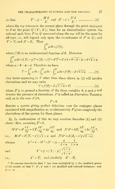
THE CHARACTERISTIC FUNCTION AND THE EIKONAL 27
so that Y=y+-jT- and Z-«+-^, (1)
where the ray intersects the normal plane through the point conjugate
to at the point Q'( Y', Z') ; then for an aberrationless system the
reduced path from P to Q' measured along the ray will be the same for
all rays, i.e., will depend only upon the co-ordinates of P ov Q' ; and
y'=FiandZ' = Z,. Thus
Jp
where /(^) is an undetermined function of 0. Moveover
f fxds={(Y,-yy + {Z,- zj + d'}^ = d ^/l + e - 4> + i{, ^ d\/l+u,Jp'
where u = 0—ff> + tl/. Therefore we have/•p' /•«•
fQ' ,V= fjids=-j fids- ,jids=/(0)-d\/l+u (2)
Any terms appearing in V other than these shewn in (2) will involve
aberrations and we may write
V=f(6)-dJV^ + F, (3)
where i^is in general a function of the three variables 0, ^ and ij/ ^-nd
denotes the presence of aberrations. F is called an Aberration Function
and, as in the case of § 8,
F=0denotes a system giving perfect definition over the conjugate planes
associated with magnification m: or alternatively i^ gives completely the
aberrations of the system for these planes.
11. In confirmation of this we may combine formulae (1) and (2)
above ; thus, assuming F=0,dV dV dV dV dV
M'd' - ^^ = 2 r. ±^2y ,; and N'd^ = 2Z. %^2^»,i.e., ilt/'c?^-c?(F,-y)/v/l +w and N'd'' = d{Z^-z)\^\V^\
whence L'"=\-M"''-N''^\-1 H- M 1 + M
and F = ?/ + ( y, - ?/ ) --^-_^-.,
v'l + u
i.e., F' = Fj and similarly Z' = Zi.
* We assume henceforth that V has been multiplied by J, the modified power
of the system, so that Y', Z', xf and z' are modified and reduced distances; and
d— s-vi.

28 THE CHARACTERISTIC FUNCTION AND THE EIKONAL
It will be seen that the partial differentiations employed above do
not involve the variable 6 and the function f{6) is arbitrary; it maytherefore be determined so as to satisfy other conditions and the con-
ditions chosen are the point-to-point correspondence of the axial points
of the pupil planes.
12. Elementary Properties. In § 6 we have taken base points and0' which are conjugate axial points associated with magnification m; if
now we take new base points Ox and 0/ associated with magnification
W] and denote by the siiffix unity the corresponding eikonal and aberra-
tion function we shall have new variables ai, /Sjand yi , in accordance with
(3) § 6 ; and we may write down the relation between {u - <^) and (m - ^)i*.
It is clear then that ^ = does not imply $i = : thus if we have
perfect definition over the planes m we shall not necessarily have perfect
definition over any other pair of conjugate normal planes. In other words
a symmetrical optical system is designed in general for only one position
of the object or of the image.
But if we consider only the first powers of the variables the aberration
function will not appear; and then we have perfect definition—to this
degree of approximation—over all normal planes ; and it is of interest
to verify the elementary properties of the system by the use of the
eikonal function. Thus
and Y=\^=l{M-mM'), Y' = - ^^, = M-mM'
;
so that Y' = 'mY and Z' = mZ. Further, if ?w = 0,
Y' =M and similarly Z' - iV^;
all rays parallel before refraction pass therefore, on emergence, through
a point upon the plane defined by m=-- 0; in particular if M= N = 0,
i.e., the incident rays are parallel to the axis of the system, they will
pass afterwards through an axial point, viz., the second principal focus.
Similarly for the first principal focus and focal plane. Again, we may
define the unit planes by the relation f fxm = /x' ; in which case
Y'l Y=m^ (x'/ix, Z'/Z-m- /x7/x,
so that the geometrical sizes of object and image are the same. If w = 1,
r= 0, and Z= 0, we have Y' = 0, Z' = 0, and also
M=M', N^N\* See Chapter v.
t m is the reduced magnification of § 11, Chapter i.

THE CHARACTERISTIC FUNCTION AND THE EIKONAL 29
i.e., we have defined the nodal points. Further, in general, for fixed
axial points
M- mM' = 0=N- mN',
i.e., in the usual notation
)Li/sina = const., (1)
or as an approximation to this
fila = const.,
as given by Robert Smith* and Helmholtz, More generally
M-mM' = mY=Y^, N-mN' = mZ=Z,, (2)
so that for all rays through a given object point these expressions are
constant; and this 'cosine law' is an extension of the sine-relation (1) into
the outer parts of the field. It will be considered more fully in a
subsequent chapter.
The relations (2) may be obtained in a more general way; thus if we
assume perfect definition over the conjugate planes m we shall have 4> =
and then U=/{y), so that
dU
_
2(M-m3r) d/ W
_
2{N-mN') df^ ~ dM~ d' 8y' dN" (P dy'-
i.e., YjZ= {M- mM')l{N- mN') and Y' + Z^ = 4y {^f^
.
From these it follows that M—mM\ N- mN' and y depend only upon
the particular point of the object from which the ray originates.
REFERENCES
Bruns, H. Das Eikonal. Saechs. Ber. d. Wiss. xxi (1895).
Hamilton, Sir W. R. The Mathematical Papers of Sir WiUiam Rowan Hamilton,
vol. I. Oeometrical Optics (Cambridge, 1931).
Klein, F. Ueber das Brunsche Eikonal.
Maxwell. On the Application of Hamilton's Characteristic Function to OpticalInstruments.... Proc. L. M. S. vi (1874-5).
Moebius, A. F. Leipziger Berichte, vii (1855).
Smith, T. Trans. Opt. Sac. xxiii (1921-2), No. 5.
Dictionary/ of Applied Physics, Art. 'Optical Calculations.'
Proc. Opt. Conv. 1926, Part ii, p. 740.
Steward, G. C. Phil. Trans. A, 225 (1925), Part i.
Trans. Camb. Phil. Soc. xxiii, No. 9 (1926).
Proc. Opt. Co7iv. 1926, Part ii, p. 778.
Thiessen. Beitrage zur Dioptrik. Berl. Berichte, 1890.
* Compleat Opticks, Cambridge, 1738.

30 THE GEOMETRICAL ABERRATIONS
CHAPTER III
THE GEOMETRICAL ABERRATIONS
1. General Properties. We have seen in the previous chapter that
the aberrations of a symmetrical optical system are given completely
by an aberration function and we have already defined two forms of
this function, viz., the <^ of § 8 and the F oi%lO: let us consider for a
moment the former of these functions. The wandering of the ray from the
ideal focus is given by the relations
Now <I> is a function of the three variables a, /? and y introduced in § 6,
Chapter ii, and inasmuch as the aberrations belong to the second and
higher approximations we may write
*= i ^n, (2)•n=2
where <t>„ is a homogeneous function of degree n in the variables a, ^and y. Each term in $ will give rise to 'an aberration' and the group
of terms denoted by ^„ will give aberrations of one particular order, viz.,
of order w — 1 ; for it is convenient to name those corresponding to the
lowest term in (2),^ig, the 'first order' or 'primary' aberrations. The
number of terms in $„ will be i (w + 1) (n + 2), so that there is apparently
this number of aberrations of order {ii- 1); but any term containing
y only is annihilated by the operator (1) above, and one such term will
appear in every function $^. Thus the total number of aberrations of
order (^^ - 1) is ^m(w + 3)*; we have therefore y?yg of the first order,
nine of the second order, fourteen of the third order and so on. These
five primary aberrations are the so-called 'five aberrations ofvon Seidel' t;
but in tills connection it is of interest to note that all five of them were
discussed by Herschel, Airy, Coddington and Hamilton % before the time
of von Siedel, and to Airy is due also the Petzval ' condition relating to
the curvature of images—as far at all events as it refers to the combina-
tion of thin lenses. This condition will be examined in detail subsequently.
2. Change of Focus. The formulae (1) § 1 give the departures from
ideal imagery upon the Gaussian conjugate plane; it is important to
consider also the intersection of the emergent ray with neighbouring
* Rayleigh, Collected Works, v, p. 453. t I^id. p. 456.
X Cf. especially 'On the Optical Writings of Sir William Rowan Hamilton', Math.
Gazette, July 1932, vol. xvi, no. 219.

THE GEOMETRICAL ABERRATIONS 31
planes so that out-of-focus effects may be investigated. Let E be the
axial point of the exit-pupil and P^ the ideal image upon the Gaussian
plane O'P^P' and let an emergent ray QP' cut the pupil plane in Q'
and a normal plane distant X from 0' in P" ; X is supposed small.
Let EP^ intersect this plane in E^\ EP^ will be named the 'central
line': let P/ be the orthogonal projection of P^ upon the normal
plane O'E^P".
P"
E O' O"
In conformity with the previous notation the co-ordinates of Pj will be
Fi, Zi; of F, T, Z , of Q', y, z' and those of P", F", Z": and
GO" = X, EO' = d = s~ m. Then
d{Y"-Y') = X{Y'-y), d{Z"-Z') = X{Z-z')-
so that d{Y"-Y,)=d{Y'-Y,) + X{Y,-y'),
d(Z"-Z,) = d(Z-ZO+X(Z,-z'), (1)
since X, Y' - Y^ and Z - Z^ are small. These equations give the
aberration displacements upon the out-of-focus plane X and we mayomit the terms XY^ and XZ^ provided that we change our origin from
Pi' to Ex upon the central line.
3. The Primary Displacement. Considering now the function $ let us
examine in detail the first order aberrations: we write
*2 = g {o-ia' - 4(r2a/3 + 20-307 + 40-4^'- i(T^^y + <y^f\, ...(l)
the variables being those of § 6, Chapter 11. The numerical coefficients
appearing here are inserted for subsequent simplicity; they are suggested
by the expansion of the expression {a - 2b + cf which occurs in the focal
eikonal to be evaluated subsequently. The coefficients o-i, . . . o-g are known
as ' aberration coefficients ' and as will appear shortly they control com-
pletely the first order aberrations of the system.
Now to the first approximation we may neglect aberrations and we
have
so that
(s — rnf
2m '
Y = ^ir = -(^-f^^') and similarly Z^^-(N-mN'\dM m^ m^ ^
Similarly p cos <f>=M- sM' and psincj> =N - sN', •(2)

32 THE GEOMETRICAL ABERRATIONS
p and<f>
being polar co-ordinates of a point upon the exit-pupil given
by the magnification s ; so that
a(P:^p\ /8(^ = pFiC0s<^, ycP=Yi% (3)
where Zi = 0.
From §1 therefore we have
i.e., d{Y'-mY) = -2{M-sM')^^-{M-mM')^
^-2pco^<t>^-Y,^^, (4)
and similarly d {Z' - mZ) = - 2p sin
.(5)
da'
Substituting, therefore, and using (1), (2) and (3) we have
2d''(Y'-mY) = (r^S + <T^C+ (0-3 + 2ar^)A+ <t^D,
2d\Z'-mZ)=<T^S' + <T^C' + ij^A',
where
S _ 3Cos<^. C^ ^(2-hcos2<^). ^__ cos<^. n-v^S"^~^ &m4>* G'-P ^' sin2«^ ' A'- ^"^^sin*^'
U-^^.
Equations (5) give completely the departure from ideal imagery as far
as the first order aberrations are concerned.
4. Spherical Aberration. Let us consider the first coefficient o-j
appearing in (5) § 3 ; we have
F'-mF=-|^gycos«^, Z'-mZ=-'^{^^\m<i.. ...(1)
It is evident that if we write Fj = 0, i.e., if we consider an object point
upon the axis of S3anmetry, this term in o-i is the only one remaining
in (5) §3; so that this is the only first order axial aberration. We maywrite here, and generally, also ^i = 0; then (1) indicates that the ray
cuts the image plane through 0' upon the circumference of a circle,
centre 0' and radius -^ f;^) > so that for a vanishing p the rays will pass
through 0': for any other value of p they will intersect the axis at some
point Oi where from the figure OiO' -~y^\ . This is called the 'longi-
tudinal' aberration; OP" is the 'lateral' aberration. Moreover, in general,

THE GEOMETRICAL ABERRATIONS 33
the rays will all touch a 'caustic' surface of revolution obtained from
the curve8^ + 27o-i3r = 0, •• (2)
where 0' is the origin of co-ordinates and the axis of x the axis of the
system. Let an extreme ray cut the caustic surface in Qo and draw iVQo
normal to the axis ; then all rays intersect the normal plane throughNwithin a circle of radius iVQo of magnitude —' \q\ , so that SOiN=NO\
It is clear that this circle is the smallest circular area of illumination
for any position of the receiving plane and there has been attached to it,
therefore, by writers on geometrical optics, a special significance from
the point of view of focussing.
Thus all the properties of the figure depend only upon the coefficient o-j
and this aberration is known as 'spherical aberration.' We have assumed
an incident beam free from aberration, but this is not necessary; for
otherwise we have merely the increment in aberration and it may be
verified immediately, using the results of Chapter v, that the above
result giving the longitudinal aberration leads at once to the formulae
usually given*.
Again we have written Fi = and this is not necessary; for if
Fi 4= the whole investigation applies as above, in the absence of the
other aberrations, except that the central line is now taken instead of
the axis of the system,
5. Coma. We consider next the terms in a^ for which we have
Y'-mY=^'P^'(2 + cos2<f>), ^-mZ=^^^^sin20; ...(1)
* Herman. Geometrical Ovtics eb«Ji vrn.

34 THE GEOMETRICAL ABERRATIONS
circle of radius
so that, if we take now our origin at the point P,, this indicates that
corresponding to an annulus of the exit-pupil
of radius p we have upon the image plane a
^ j (—f), the centre being
at the point ^zi-i) {~t)) ^' -^or variations
of p both centre and radius change; but it is
clear that all the circles touch two straight lines
through Pi, symmetrically placed, and inclined
to one another at an angle of 60°. All the
illumination therefore is contained within this angle, being more intense
towards the head Pj; so that we have the comet appearance or 'coma'
flare. This aberration accordingly is known as 'coma,' or better 'circular
coma,' to distinguish it from what follows*. From the occurrence of 2<^
in (1) it is evident that a single description of the exit-pupil implies
a double description of the corresponding coma circle, and also that rays
from diametrically opposite points of the exit-pupil intersect upon this
circle, i.e., upon the Gaussian conjugate plane. This implies that change
of focus will be of no benefit with this aberration. We have also
^«=?(S)"(t) • (^)
where C is the centre of a coma circle which is met by PiC in G.
The coefficient a-^ therefore governs completely the first order circular
coma.
6. Astigmatism and Curvature of the Field. The two coefficients 0-3
and 0-4 occur together in (5) § 3 ; we have
F'-wF = - |(o-3 + 20-4)^(^'Y cos <^, Z'-mZ=- ^0-3 1 {^^ sin ^
(1)
these equations indicate an elliptical displacement from the Gaussian
conjugate, the axes of the ellipse being proportional to (0-3 + 20-4) and
0-3 respectively. Let us consider, in the first place, rays in an axial
plane passing through the object point F, i.e., ^1 = or tt.
If Pi be the Gaussian conjugate and Ei the centre of the exit-pupil
the first of the relations (1) indicates that the two rays corresponding
to (^ = and tt intersect in a point Pi upon the central line ^'iPi ; the
* Viz., 'elliptical coma' in §11 and 'generalised coma' in §13.

THE GEOMETRICAL ABERRATIONS 35
aggregate of such points i^i for various positions of the object point will
give a surface. Moreover if x be the distance of F^ from the conjugate
plane we haveX
d — X -H<^,-2..)^(^y,
I.e.,/F\2
^ = - 2 ((^3 + 20-4) f -vM (approximately), (2)
since x is small; the negative sign indicates that F^ is in front of the
conjugate plane for positive values of ctj and 0-4. Relation (2) shews that
the locus of i^i is a surface of revolution about the axis of the system andthat the curvature of this surface is (0-3 + 1a-^\d^; but this is the modified
and reduced curvature. We have assumed here that the object surface
is plane ; if however it be a surface of revolution then the expression
just obtained is the increment in curvature of the image surface; so that
if Ux be this latter curvature we have
AW- (<^3 + 2o-4)/^^ (3)
The surface which we have just obtained is known as the 'primary'
surface; we may similarly obtain a 'secondary' surface by considering
rays for which ^ = -^ or — ; these will intersect in a point F^. upon E^^P^
and the aggregate of such points will give the secondary surface. If jRj
be the curvature of this, we have
A(i2,) = o-3/o?^ (4)
Moreover from (2) the separation of the surfaces is given by the
expression
H-.(^-)' .(5)

36 THE GEOMETRICAL ABERRATIONS
Now we may write (3) and (4) as follows:
A (T^i) = 3o-4/(^ + t!r, (6)
and £^{R^) = (Tjd' + v:, (7)
where rscP = o-j - o-^
,
In the general case this aberration is known as 'astigmatism'; from
(5) if 0-4 = the surfaces coincide and we have simple ' curvature of the
field': i.e., a normal plane in the object space is transformed into a
surface of revolution. From this it will be seen that, in general, the so-
called 'cardinal planes' are not plane at all but, instead, surfaces of
revolution. If in addition ra- = the surface becomes a plane; this, there-
fore, is the condition for flatness of field, i.e.,
CTC?2= 0-3-0-4=0; (8)
this is known as 'Petzval's condition for flatness of field,' and ro- is the
'Petzval Sum.' These results will be evaluated more fully for actual optical
systems subsequently; we are concerned here only with the qualitative
nature of the aberrations.
From §2 the points of intersection of the ray with a plane a distance
X in front of the paraxial image plane are given by
n=[x~h (<r, + 2<T,)
(^^yi^C0S<^, i= {X- i<r3
(^^)] ^ sin <t>,
(9)
where v, C are co-ordinates referred to the 'central point' Bi of §2 as
origin. Now (9) will represent a circle, the 'least circle of confusion,' if
2Xd' = i<T, + <r,) Y,'; (10)
otherwise the area of illumination will be elliptical. Here the receiving
plane bisects -Fii'l and this accordingly will be the position of best focus
according to the geometrical theory. Again, if either of the bracket terms
in (9) vanish the area of illumination will reduce to a straight line—the
'focal line'; and this occurs when the receiving plane passes through JF^
or F2. It is clear from (10) that the centres of the various circles of least
confusion, corresponding to different positions of the object, will all lie
upon a surface of revolution of curvature (0-3 + a-i)/<p and touching the two
'image' surfaces in their common axial points.
Again, it appears that astigmatism and curvature of the field are
governed completely by the two aberration coefiicients 0-3 and 0-4.
7. Distortion. We have finally to consider the coefficient 0-5; from
this we obtain
Y'-mY=^cr,(Y,/dy, Z'-mZ^O (1)

THE GEOMETRICAL ABERRATIONS 37
These relations indicate a motion of the representative point from the
ideal image away from, or towards, the axis of the system according as
o-g be positive or negative; and further the magnitude of the motion
varies as the cube of Fj. Let us consider the image of a network a
placed normal to the axis of the system ; if as be positive the image is as
r^
fi while if 0-5 be negative we have the case of y. We are dealing here
with ' distortion ' and it is known as ' pin-cushion ' or ' barrel ' distortion
according as it corresponds to y8 or to y, i.e., according as 0-5 is positive
or negative.
It has appeared from the preceding discussion that there are Jive
aberrations of the first order—the so-called ' five aberrations of von
Seidel'; and that they are given completely by the five 'aberration
coefficients' o-i, cr^, 0-3, 0-4 and ar^. Lord Rayleigh has remarked that
they do not stand all upon the same level; for three of them refer to
errors of focussing (spherical aberration, coma and astigmatism) while
two refer to the position of the focus, (curvature of the field and
distortion).
8. Aberrations 0/ Higher Orders. We may deal with the aberrations
of higher orders after the manner of the preceding paragraphs, for wemay use in succession the functions ^3, ^4, ... $„, ...; but we propose
now to use the Characteristic Function, partly as an example of its use
and partly because of its greater convenience in dealing with diffraction
phenomena. In the notation already introduced V, and also the aber-
ration function F, are functions of the variables 6, <f> and f; and wehave the relation
V=/(0)-dJTMi + F. (1)
Moreover the inclination of the emergent ray to the axis is given by
so that
M'd'
Again,
M = -^— and iV^ = ^r^
;
cy dz
= 2(f,dV ,dV\
and N'd^ = 2 )....(2)
Y'^y' + M'djL' and Z' =z' + N' djL'
;

38 THE GEOMETRICAL ABERRATIONS
SO that, substituting from (1) in (2), we have
<.(r-F,).2(r.f .,-f) and ^(Z'-;^.) =
2(^,f-'f).
^ (3)^
retaining only the terms of lowest order; where we have written jP„ in
place of i^in (1). In general F will be the sum of such terms as Fn where
the latter function is homogeneous and of degree n in the variables, so
that, in effect, we are restricting ourselves to aberrations of one order,
the (« - l)th. Again we may write
Fn=^^^A^,,,re^<i>W,
where ^ + q^ r = n, and then substituting in (3) and remembering that
the polar co-ordinates p, ^i* correspond to y\ z we have
•(4)
Y'-Y, = 2^A,,,,r (^) (^)cos^-^ «^, {2r cos^ <f>, + q],
Z-Z, = 2'^Ap,,,r[^) Q 2r cos'' <t>i sm «^i,
corresponding to the term ^p.^.r, where we have written Zi = 0, as is
always legitimate. These formulae (4) give completely the aberration
displacements of order (n-l) exhibited in powers of Y^ and p, and
taking w = 2 it may be verified directly that they agree with the results
of the preceding sections. In fact if we write, for the first order aberra-
tions,
F2 = a^O"^ + a^B^ + asBij/ + a^^y^ + a^cjuj/ + agi/'^
the coefficients here correspond to the o--coefficients of the eikonal ; and
we have o-j + Sag = 0, 0-2 = 4^5, 0-3 + Aua = 0, 0-4 + 8^4 = and 0-5 = 4a2-
9. It is not proposed to examine here the higher order aberrations
in detail; for this reference may be made elsewhere!; but only such of
them as present peculiarities. And for those of the second order we may
write
Fs^b.O' + b,6''<f> + bse'xp + bM' + h04>^
+ b^eyii" + b'!<t>^ + bs<k''^ + b9<l>il/^ + b,oV'
The coefficient 610 gives spherical aberration, depending however upon
the fifth power of the radius of the exit-pupil; but this type of aberration
will follow whenever ij/ appears alone. Consider a term An^" appearing
in F; then from (4) §8 we have
(P^-^(Y' - Y,) = 2nAnP"''-' cos <^>^, d^-'(Z' -Z,) = 2nAnP'''-' sm<i>,*;
*(pi replaces the (j> of §§ 1-7 : it is used for distinction from the function <p of
Chapter 11, § 10, introduced with the Characteristic Function,
t Trans. Camb. Phil. Soc. xxiii, No. 9, 1926.

THE GEOMETRICAL ABERRATIONS 39
and this clearly repeats the investigation of §4. It is seen, therefore,
that for spherical aberration of order n, the lateral aberration depends
upon the (2w + l)th power of p while the longitudinal aberration depends
upon the 2wth power of p ; and for an axial object point this is the only
type of aberration which will appear.
Taking now the term in h^, this represents circular coma, but it maybe investigated for the general case; for if we have a term -4„+i^i/''*
appearing in the aberration function F this will give, on substitution
in (4) §8,^™+i
(^ Y' - Fi) = 2An^^ Y^p"" (n cos 2<f>, + n + 1),
c?2'^+i (^' _ z,) = 2n An+, Fip^" sin 2<^i,
and this repeats the investigation of § 5. The displacement curve is as
in the diagram of that paragraph but the angle between the tangents is
no longer 60° but 2 sin~^ n/(n + 1), the length Pi G being given by the
relation d^+'P^G = 2An+i Yi p'".
This aberration may be named 'circular' coma of order n, to distinguish
it from other types of coma, to be examined later, in which the dis-
placement curve is no longer a circle*.
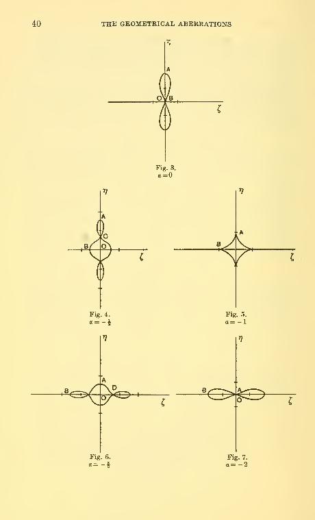
10. The coefficients be and bg fall naturally together and from (4). §8
we haver) = (cOS^^i + 1 + a) cos ^i,
,
C - (cos^<^i + a) sin <^i,
where 8bsP^Yi^r] = d^(Y' —Yi) and a similar expression for ^ and Z;and 20^8 = be . Thus r] and 4 are current co-ordinates referred to the ideal
image point as origin and (1) gives the displacement curve corresponding
Fig. 2.
a=l§ 11, 13.
40 THE GEOMETRICAL ABERRATIONS
A
Fig. 5.
a= -1
T^ I
Fig. 6.
O^CD
Fig. 7.
a= -2

THE GEOMETRICAL ABERRATIONS 41
to a given value of p, the radius of the exit-pupil. The curve varies
considerably in appearance according to the value of a, and the diagrams
shew some typical cases. For varying values of p, i.e., of the exit-pupil,
the curves vary in size, but not in shape, inversely as the cube of p ; so
that each of the curves may be regarded as the shape of the illuminated
area for that particular value of a. Fig. 5 is of interest ; its equation is
and gives the minimum area for a given value of ^s-
11. Consider now the terms in h^ and h-r and substitute in (4) § 8
;
we haved\Y'- F,) = 2p2 Fi^ {b, (2 cos^<^ + 1) + 1267 cos^ <i>,],
d' {Z' - Zi) = 4p" F/^s cos <^i sin «^i
;
or, as in the previous paragraph, we may write
T/=(l -(-a)cos2<^i + 2 + a, ^==sin2^i, (1)
where abs^Gby. In general (1) represents an ellipse with centre Cupon the axis of rj, and sjonmetrically placed with respect to that axis;
and this corresponds to a narrow rim of the exit-pupil of radius p. For
varying values of p all the ellipses so obtained will touch two fixed
straight lines passing through the origin ; so that we have something
very similar to coma, discussed in §5, and again we have a double
description of the curve for a single description of the exit-pupil. This
aberration may be named 'elliptical' coma: the angle between the
tangents is 2 cot"^ J3 + 2a. It is clear that if 65 vanishes we have just
a radial distortion along the T;-axis and the aberration curve reduces
merely to a portion of this axis; if a + 1 = the curve is a straight line

42 THE GEOMETRICAL ABERRATIONS
perpendicular to the 77-axis, for one of the axes of the ellipse will vanish.
In this case corresponding to a point source of light in the object space
2n-i( Y' - Y,) - 2p Yr-' (a + 4/3) cos <^i , 1 /!>)
P™-i(Z'-Z0 = 2pFi^"-^asin<^i. /
we have a triangular patch of illumination upon the conjugate plane,
as in Fig. 2.
12. The terms in 63 and 64 fall naturally together; but they may be
considered in a more general way; for if we have terms a^"-V and
l^$n-2^2 appearing in the aberration function i^then upon substitution
in (4) § 8 we obtain
d'
These relations clearly represent astigmatism of order (w — 1) and they
indicate two images and two image surfaces according as we consider
a primary or a secondary plane ; and the surfaces coincide only if /3 =
—the field being flat if in addition a = 0. In general the astigmatic
separation 8 is given by
8(^2«-2^8/SFi''"-' (2)
And again the term in b^ may be examined from the general point of
view; for a term a6"^~'^<f> in the aberration function i^ will imply, by (4) §8,
the relations
d^n-i( Y' - Y,) = 2a Yr-\ Z'-Z, = 0',
and this clearly indicates distortion proportional to the (2w — l)th
power of Yi, being 'barrel' or * pin-cushion' distortion according as
a$ 0.
13. The Third Order Aberrations. We may investigate the aberrations
of the third order by considering i^ to be a quartic function of the
variables 0, <f> and if/ ; but the aberration curves introduced will be very
similar in appearance to those discussed in previous sections—with one

THE GEOMETRICAL ABERRATIONS 43
ia.l
•(1)
exception*. And this exception will arise from the terms in F of the
form
substituting in (4) § 8 we have corresponding displacements given by
d'{Y'- Fj) = 2p* Y-,^ {8ci2 cos" ^, + (12c,2 + 4C9) cos^ 4>i + C9},
cf {Z' - Zi) = 2p* Y^ {8ci2 cos' </>! + 4C9} sin <^, cos c^i
.
These may be written, as in preceding paragraphs,
t) = cos 4^1 + 2 C5 + 4a) cos 2^i + 9 + 12c
C = sin 4^1 + 2 (1 + 4a) sin 2^i,
where 09 = 4ac,2, 17 and ^ being current co-ordinates referred to parallel
axes with the Gaussian image as origin. These displacement curves are
periodic in ^1 , the period being tt, so that half the rim of the exit-pupil
corresponds to the whole perimeter of the corresponding curve ; more-
over they are symmetrical about the line <^i = 0, i.e., about the 7?-axis.
And for a given value of a, and varying values of p, they all touch fixed
tangents passing through the origin of co-ordinates ; but these tangents
become imaginary for certain ranges of values of a. It is clear, therefore,
that we are dealing with an aberration of a generalised coma type.
The aberration curves vary in appearance with the value of a ; the
diagrams given shew a representative selection of such values, and it is
to be understood that each curve corresponds to an annulus (or rather
to half an annulus) of the exit-pupil of radius p—the dimensions of the
curve varying as the fourth power of p.
Fig. 2.
0=0
• Cf. below, § 16.

44 THE GEOMETRICAL ABERBATIONS
Fig. 3.
80 + 3=0Fig. 4.
2a + l=0
Fig. 5.
4a + 3=Fig. 6.
a + l =

THE GEOMETRICAL ABERRATIONS
1
45
Fig. 7.
a + 2=
14. The Combination of Aberrations*. In the preceding paragraphs
the aberrations of any particular order have been considered alone; but
in fact the displacements of the second order will be modified by the
coefficients of the first order—assuming that these have not been
eliminated ; so that there is revealed the possibility of the combination
of aberrations, and further, of the balancing of aberrations. As a simple
example we find that, if we consider only aberrations of the first two
orders and confine ourselves further to an object point situate upon the
axis of symmetry, the radius of the illuminated disc upon the paraxial
image plane is ^^^^z + 6 (a, + b,o) pA
Pi being the radius of the exit-pupil. The second order displacement will
vanish, therefore, for all values of pi if ag + b-n, = 0, while spherical aberra-
tion, as a whole, will vanish only if both coefficients are zero ; but very
frequently a lens is designed so that the paraxial and marginal foci co-
incide at full aperture (or at a partial aperture) and then we have
2a6-H3(a6 + Mpi' = 0, (1)
a relation giving a^ when b-^o is known. So that the effect of axial aber-
ration can be diminished by a proper choice of the a-coefficient
—
supposed under control—without a change of the 6-coefficient. Higher
order axial aberrations often have to be taken into account, as for
example in the design of microscope objectives, but the principle remains
* Cf. Trans. Camb. Phil. Soc. xxiii, No. 9, §§ 12, 13, 20 and 21.

46 THE GEOMETRICAL ABERRATIONS
the same; and again similar effects must be considered with the
other aberrations of these and of higher orders. Thus the aberration
displacements of any order can be modified profoundly by a choice of
the coefficients of lower order.
Again we have to consider, from a geometrical point of view, the
effect of change of focus in the presence of aberrations in general; and
this may be effected by an application of § 2. In particular with circular
coma of the first order, the displacement curves upon neighbouring
planes are somewhat complicated—even those corresponding to a narrow
rim of the exit-pupil. But this may be contrasted with the diffraction
phenomena to be investigated later*.
15. Change ofFocus. The effect of change of focus maybe investigated
by means of the results given in § 2, and we shall obtain displacement
curves, upon out-of-focus planes, corresponding to an annulus of the
exit-pupil; a simple case of this has already been given in § 6. We mayinvestigate also, in this way, the caustic surfaces arising from the presence
of aberrations of various types. The out-of-focus aberration curves
corresponding to the comatic aberrations will in general be of a com-
plicated type; as a simple example we discuss the case arising from first
order circular coma. Thus combining § 2 with § 5 we find that the dis-
placement, upon an out-of-focus plane, due to this aberration is given by
r; = cos 2</>i- a cos <^i + 2 + )8, C = sin 2<^ - a sin <^i (1)
Here d^{Y"- Y,) ^ 2a, Y.p'v, d' {Z" - Z,) = 2a, Y, pH,
and Xd^ = 2a, Y,pa = 2a,p^/3;
so that 7} and ^ may be taken as current co-ordinates in the usual way.
Equations (1) give the displacement curves corresponding to an annulus
of radius p of the exit-pupil and the numerical term 2 indicates that the
origin has moved along the T?-axis a distance proportional to p^
The curves are clearly periodic in <ji, the period being 27r here instead
of IT, as for the Gaussian plane (i.e., a = 0); also they are symmetrical
about the ry-axis. Moreover the curves on one side of the Gaussian plane
a = are exactly similar to those on the other side except that they are
rotated through two right-angles.
Three curves are shewn in the diagram corresponding to the focussing
planes a = i, 1 and 2 ; for the complete circular aperture the effect will
be due to a superposition of these curves combined with a progressive
change of origin proportional to the square of the radius of the exit-
pupil. This complicated effect may be compared with the modification
due to diffraction to be investigated subsequently*.
* Cf. Chapter vii, §5.

THE GEOMETRICAL ABERRATIONS
7 7J
47
a=2
16. Some General Remarks. Let us consider the aberrations of any-
particular order, in the absence of those of lower orders ; we have an
aberration function F and corresponding displacements as in (4) § 8,
and combining these with the formulae of § 2 for out-of-focus effects the
whole displacement upon a receiving plane normal to the axis of the
system is given by a sum of a number of terms alternatively of the
types S and C given below, viz.,
i7=(2 ^23Cos^<^i-/x.)cos^i, ^==(2 ^2sCos-''^i-/u.)sin^i, Ss=0 s=0
and
7/= 2.4'2sCOS^<^i-/A cos<^i, ^=(2 5'2sC0S^''<;^i)sin^iC0S^i-/isin<^i....(7s=0 s=0
Here -q and ^ are current co-ordinates relative to the central point as
origin and /x denotes a displacement from the paraxial image plane ; in

48 THE GEOMETRICAL ABERRATIONS
fact ^t.d = JCp, in the usual notation. The coefficients contain as factors
powers of p and Fj , and those coefficients occurring in any one of the
types S and G contain severally some particular power of p and a
particular power of Y^ ; moreover the >S'-type arises from even powers
of 3' in § 8 so that p occurs to an odd power, while in the C^-type p occurs
to an even power. All the aberrations may be classified therefore
according as they fall under one or other of the above two types, which
may be named respectively the 'spherical' type and the 'coma' type;
or the 'symmetrical' and the 'unsymmetrical' tj^e.
For the spherical type let us write, in the first place, /x = and so
consider the paraxial image plane ; it is evident that the corresponding
displacement curves are closed and periodic in <^i, the period being 2ir,
and that an increase in ^i, of amount tt, serves merely to change the
signs of both -q and ^; moreover the curves are symmetrical with respect
to the co-ordinate axes. Thus the origin is within (or upon) each curve
and as p decreases from its maximum value to zero each curve collapses
to a point at the origin, remaining always similar and similarly situated.
This may be compared with the simplest case of this type, viz., axial
spherical aberration. Again change of focus is beneficial, in general, i.e.,
the area of the resulting light patch may be diminished in this way, and
we may find the least curve of aberration—corresponding to the least
circle of aberration of § 4. It is evident that the largest value of p, the
radius of the exit-pupil, will give the area of illumination upon the
receiving plane.
Turning now to the coma ty^Q, it is evident that, if /a = 0, the
summations C may be written as functions of 2^i, the equation for r]
involving also a term independent of 4>i but containing p and Yij and
this latter term implies a change of origin along the 77-axis. The dis-
placement curves are sj^nmetrical with respect to the axis of r] and are
periodic in <^i, their period being tt, so that half of the perimeter of the
exit-pupil corresponds to the whole of the aberration curve. For varying
values of p the new origin moves along the T/-axis and two cases arise
;
either (1) any curve, and so each curve, has the old origin, i.e., the
Gaussian image, within (or upon) it ; or (2) the origin is outside each
curve. In the second case we have a family of curves all touching real
fixed tangents passing through the Gaussian image and collapsing to a
point there as p tends to zero ; and this may be compared with circular
coma discussed in § 5. In the former case we have something similar, in
some respects, to the spherical type of aberration; the fixed tangents
have now become imaginary.

THE SINE-CONDITION AND THE OPTICAL COSINE LAW 49
Again, in the more general case in which /* #= 0, and we consider an
out-of-focus plane, it is clear from the summations above that an addition
of -n- to <t>i, together with a change in the sign of fM, leave the expressions
C unaltered; so that the displacement curves are symmetrical with
respect to the paraxial image plane, indicating that change of focus is
of no advantage with the coma type of aberration.
Each order of aberration brings with it an aberration of a new kind,
for an additional power of cos^ ^i appears in one or other of the sum-
mations /S* and C; and further the new kind of aberration falls alternately
under these types. If the order of the aberration be even the new dis-
placement is of the spherical tjrpe, if odd it is of the coma type : thus
the only aberration of zero order is that due to a shift in the focussing
plane and is spherical in type ; the essentially new aberration of order
one is coma, of order two it is that examined in § 10 and belongs to the
spherical type, while of order three it is as in § 13 and is comatic.
REFERENCES
Pelletan, A. Optique Appliquee.
Rayleigh. Hamilton's Principle and the Five Aberrations of von Speidal. Sci.
Papers, vol. v, p. 456.
Steward, G. C. Tram. Camb. Phil. Soc. xxin. No. 9 (1926).
Phil. Trans. Roy. Soc. A, 225, 1925, Part i.
' On the Optical Writings of Sir William Rowan Hamilton,' Math. Gazette,
July 1932, vol. xvi, no. 219.
von Seidel. Astron. Nachrichten, 836, 871, 1027, 1028, 1029.
CHAPTER IV
THE SINE -CONDITION AND THE OPTICAL COSINE LAW
1. Ths Sine-Condition. Object glasses of telescopes, after being
polished, are usually finished off by a process of 'figuring'; i.e., the
material of the glass is removed so that a non-spherical surface of
revolution is obtained and the process is continued until the definition
for points near to the axis of the system is found to be satisfactory.
The method is therefore one of trial and error. Now very good object
glasses were fashioned by Fraunhofer in this way and it was found long
afterwards that they satisfied very nearly a certain condition—the well-
known 'sine-condition' ; and the better the definition near the axis the
more nearly did they satisfy the condition. It is our object to investigate
the reason for this and to find out the meaning of this 'sine-condition.'

50 THE SINE-CONDITION AND THE OPTICAL COSINE LAW
The meaning of 'aplanatism' has been considered in Chapter i; and
defined there as the satisfaction of two conditions, one implying the
absence of spherical aberration and the other the satisfaction of a certain
relation between the sines of the inclinations of the two parts of a ray
to the axis of the system. We consider now the general symmetrical
system.
Let 6 and 0' be the inclinations to the axis of the two parts of a ray
before and after refraction; then in the notation of § 10, Chapter ii, we
have
/9FY /ery/sin^y _ M^ + N^
^ S^YJ ^\dzjVsin^V M" + N'' ^ (SJ^V (^Jl\''
\dy') ^\dz')
dVV .dVdV fdV
d4>/ sin 6^ yKm^^) "
6 /9Zy ^ . 31 L^ ^ ./SF
y
6, cf) and iff being our usual variables and L, M, iVand L' , M', N' the
direction cosines of the incident and emergent rays. If now we assume
an axial object point, i.e., Yi = m Y= and Z^ = mZ = 0, we shall have
= ^=0, while as usual \pd^ = p';&o that
/^in^y^/a_r/aFyWsin^V ~\d<f>/ dif,)
•
Write now V =f(6) - ds/l + u + F,
where i^is the aberration function; then
dV d dF+
anddV d dF
if w = ^ - <^ + 1/'; so that
/ sin^ y_\m sin B'J
2V1 + u dF^^ ^ d dcl>
2\/l + udF•0)
d dil^j
Now F is a function of 0, cf> and ij/ and we may write
where p + q + r^2: the A's are of course the aberration coefficients

THE SINE-CONDITION AND THE OPTICAL COSINE LAW 51
whose meanings have been investigated in the preceding chapter. Since
6-(f> = 0, we have
--= 2 ^0.1. nr> (2)09 71=1
dF '^
and ^=2 nAo,.,nr-'; (3)P'f' n= 2
and the coefficients of (3), viz., Ao,o,n, are those which we have shewn
to govern pure axial spherical aberration of the several orders ; in the
absence, therefore, of axial spherical aberration
and if the sine-condition be satisfied for all rays, i.e., if
sin ^ = /» sin 6', (5)
ti"^" iV '*&.!/»•• (5)=0
for all values of p.
It follows therefore by taking successive terms that each of the
coefficients Ao,i,n must vanish; conversely if these vanish the sine-
condition (5) is satisfied for all rays through the conjugate axial points
considered. Now we have seen in the previous chapters that the
coefficients ^o, i. n are those which govern circular coma of the several
orders—which depends upon the first power of the quantity ( Yi/d)
;
and this, in the absence of axial aberration, is the most important
departure from perfect imagery for points near to the axis of the system.
The satisfaction of the sine-condition, therefore, in the absence of
spherical aberration will ensure a good image of a small two-dimen-
sional object placed normal to the axis, for it implies the absence of
circular coma of all orders for the conjugate planes under consideration.
2. It is of interest to investigate the geometrical meaning of a given
departure from the sine-condition ; thus let the paraxial magnification
be m for the conjugate points considered and let the magnification as
calculated from the sine-condition applied to a marginal ray hein(l + i);
it is assumed that spherical aberration is absent for these conjugate
points. Then from (4) § 1 we have
y^^a^i^-'-m «

52 THE SINE-CONDITION AND THE OPTICAL COSINE LAW
and -4o, 1, Ti are the coefficients governing circular coma of the several
orders ; in the notation of § 5, Chapter in we have
d X"^! Or„ = 2^ 0, 1, n ^ \P >
the suffix indicating that we are dealing with circular coma of order n.
From (1) therefore
^^.=yiK^"jj/''^- (^)
and here Pi is the radius of the exit-pupil. If we consider only the first
order aberration
a result of some importance subsequently.
For a ray cutting the exit-pupil at a distance p from the axis the
corresponding value of c is given by
where now PiGn corresponds to p.
3. The Cosine-Conditions. We have seen already that for all rays
through a given object point
M- mM' = const. "l . .
and iV^- wiV^' = const. = OJ^^
ii Zi = mZ^O; and this is true only in an aberrationless system.
This result is an extension of the well-known sine-condition into the
outer parts of the field and (1) may be named the 'cosine-conditions.'
Departures from this result will imply the presence of aberrations and
we have here a condition applying to the higher order aberrations in the
same way as the ordinary sine-condition applies to circular coma.
4. Herschel's Condition. Suppose that we have two conjugate axial
points P and P' which are free from spherical aberration of all orders
;
in general neighbouring and conjugate axial points Q and Q' will not
be free from aberration but we may enquire what condition must be
satisfied so as to ensure that Q and Q' shall be free from aberration.
Herschel gave this condition in an approximate form, applying only to
first order aberration, i.e., to aberration depending upon the cube of the
inclination of the ray to the axis; and later Abbe shewed that the
condition was contained in a simpler—and more general—result ; the
final form of the condition is
sin ^/2 = m sin ^72 (1)

THE SINE-CONDITION AND THE OPTICAL COSINE LAW 53
Here 6 and 0' are the angles of inclination of the ray to the axis of the
system and m is the reduced magnification associated with the conju-
gate points considered. The condition is customarily written
/Asin 6/2 = fi'm sin 6'12, (2)
but here m is the ordinary magnification.
In the usual notation we have
V=/iO)-dJlT^+F;and from the general property of the characteristic function
Z = -^/andZ'=|^, (3)da; dx
all distances being reduced. But x= Ijm and a;' = -s, where s is the
paraxial magnification associated with the pupil planes; so that
L = nr^r— and iy =--^— (4)dm ds
We are dealing with axial conjugates so that we shall have O = (ji = 0;
moreover
dd^ = Y,^ + Z^, cfid' = 2{ Y^y + Z^z) and ^\,d'' = y" + z' = p^
so that
J^d-2i!/ = and -^ d+2il/ = 0.cm ds
If we write F= ^ ^„iA"Tl=2
in (4) we have
T ,¥(0) m',
" ,„/2w. ^^M]L = m^~^ + —== + m^ z il/"-{ -j-An + -—
)
dm Jl+d/ n=2 \d dm J.(5)
and i.' =—i=+ 2 -^ A,,rVI +«/' «= 2 ^
since An is independent of s, as also is /(O); indeed if Fx and F^ be
the principal foci of the system and P and P' the axial conjugates
associated with reduced magnification m we have
FxP=\\m and F.,P' = -m,
so that /(O) = PP = F,F, - F,P + F,P= F,F2*-l/m-m;
and '4(5).i,_i.dm m^
* The modified and reduced axial distance between the principal foci of the
system.

54 THE SINE-CONDITION AND THE OPTICAL COSINE LAW
Thus from (5) above
£-i^^. i-i/ViT^s-r
CO 9„ CO p J
where 2 = ^ -^ Anr and S' = 2 i/."^
.
If now the conjugate axial points P and P' be free from spherical
aberration, ^„ = for all values of n and thus 2 = 0; so that from (6),
6 and &' being the initial and final inclinations of the ray to the axis
of the system,
sin^/2 f,2' 1*
-'71 Y'
dAr
sm /2 I 1 - f 1 + ^) ^J
It is clear therefore that if -—^ - for all values of n, i.e., if 2' = 0,am
then the condition (1) is satisfied for all rays; and conversely by the
expansion of (7) it follows that if the condition (1) be satisfied for all
^Arays then -^r^ = for all values of n.
•' dm
Thus Herschel's condition, applied to two conjugate axial points free
from spherical aberration, implies that neighbouring axial points are
free from spherical aberration oi all orders; and conversely.
In order to investigate the meaning of a departure from Herschel's
condition let us write
/I sing/2Y_, _\m sin 6'12)
~^
for any ray ; then by comparison with (5) we have00
2 ^ V"=' "
(i + ./' + v/iT^)( 2 A:r),
where the dash denotes differentiation with respect to m; so that
€ = 2^2>='+(|^; + 2^3')'/'' + (8)
Considering therefore only a first approximation, if the magnification
as calculated from Herschel's condition applied to a marginal ray be
»2 (1 --7), we have
t-'^'i^' wPi being the radius of the exit-pupil ; and this gives a measure of the
spherical aberration introduced by a slight axial movement of the object
plane.

THE SINE-CONDITION AND THE OPTICAL COSINE LAW 55
It is seen that Herschel's condition (1) is, in general, incompatible
with the sine-condition ; the only case in which both conditions may-
be satisfied is that in which m^=l, i.e., 6' -±0. Thus it is impossible,
in general, to reproduce, without aberration, an element of space axially
situated.
5. Geometi'ical Proof of the Sine- Condition. An interesting proof of
the sine-condition, and also of Herschel's condition, was given by
Hockin in 1884, but it is approximate only and deals with small
quantities of the first order. It depends upon the fact that, if there be
perfect correspondence between two points, the one in the object space
and the other in the image space, then the optical path between them
is constant. A slight modification of Hockin's proof is given here.
Let P and P' be two conjugate points upon the axis of a sjonmetrical
optical system and supposed free from aberration and let Q and Q' be
Q'
^^'N
any pair of conjugate points in the neighbourhood ofP and P; we sup-
pose also that Q and Q' are entirely free from aberration. Let PN and
P'N' be the corresponding parts of a ray through P and P', making
angles a and a with the axis of the system, and let QN and Q'N' be
perpendiculars to this ray. The difference between the optical paths
between Q and Q', and P and P', i.e., V(QQ') and V(PP'), is given
approximately by
V(QQ')-V(PP') = ^'P'Q'cosI3'-h^PQgosIB, (1)
where NPQ = ^ and N'P'Q' = /?'; and this must be an absolute constant.
We may make specialisations of this result; thus let PQ, and therefore
also PQ', be normal to the axis PP, i.e., let /3 = 7r/2 — a and P'- 7r/2— a'.
Then from (1)/a' PQ' sin a -fjiPQ sin a = const.
= 0, (2)
since the axis PP' is a ray, i.e., a =0 and a' = must satisfy the condition.
We have, therefore, the usual form of the sine-condition ; and this is the
condition that there should be perfect correspondence in the neighbour-
hood of P and P' over normal planes passing through P and P', i.e.,
we have a good image of a ^wo-dimensional object normal to the axis
of the system.

56 THE SINE-CONDITION AND THE OPTICAL COSINE LAW
Again in (1) let us write a + /3-0 and therefore a + (B' - 0, i.e., let Qand Q' be conjugate axial points; then
fj^'P'Q' cos a - fjiPQ COS a = const.
= H-'P'Q'-f^PQ,
since again the condition must be satisfied by a = and a' = 0. We have
therefore
IJi'P'Q' sin^ a'/2 = tiPQ sin^ a/2;
or if m be the magnification of normal elements, associated with Pand P',
ft'm sin a'/2 = fx sin a/2, (3)
from the elongation formula of §(3), Chapter i, combined with §(3),
Chapter ii ; here m is the ordinary, not the reduced, magnification. Weobtain in this way Herschel's condition—the condition that conjugate
and neighbouring axial points should be free from aberration, i.e., that
an element of the axis of the system should be reproduced without
aberration.
Let us suppose now that the point P moves to an infinite distance
in the direction P'P and let Fi be the first principal focus; P' approaches
the second principal focus F^; using reduced and modified lengths wehave
F^P^l/m and a-*0,
so that the sine-condition becomes
jPiPsina^sina',
while the incident ray becomes parallel to the axis : thus if the incident
and emergent rays intersect in a point distant 3/' from the axis we have
3/' - sin a',
i.e., the locus of this point is a sphere with centre F^, the second
principal focus. The second unit surface is no longer a plane but is a

THE SINE-CONDITION AND THE OPTICAL COSINE LAW 57
sphere. Other proofs of the sine-condition have been given by Abbe,
Helmholtz, and, before these, by Clausius; the latter deduced the
condition from the second law of thermod3niamics.
6. The Optical Cosine Law. The two conditions investigated in the
preceding paragraphs, the sine-condition and Herschel's condition, are
particular cases of a very general theorem due to T. Smith—the 'optical
cosine law'; and this includes also other optical laws. We proceed to
prove a lemma leading to this law.
Let P {x, y, z) be a point upon a surface F(x, y, 2;) = and let /, w, n
be the direction cosines of some fixed direction ; if X, M, N be the
direction cosines of the normal at P to the surface we have
Let Q (^, 7;, ^) be a point upon the normal at P to the surface and
such that
PQ = pcos^,
p being a small constant quantity and B the inclination of the normal to
the direction I, m, n; so that
cos B^lL-\-mM -t- nN.
The equation of the locus of Q, is therefore
F{^- pL co^e, 7]rpM cos 6, C-p^co&0)=0,
i.e., to the first approximation it is
dF ^^dF ^^dF\
Again, if Q' ($', rj', C) be a point distant p from P in the direction
/, m, n, p being small, the equation of the locus of Q' is
F{$'-p'l, y]-pm, C-p'n)^0,
i.e., to the first approximation it is
^w'.-^-'Of^-f-f ).„..,=» (^)
Equations (1) and (2) will represent the same surface if
Xp cos = Xp cos 0,
i.e., if p = p-
Thus the locus of Q is the surface F displaced bodily, without rotation
and without distortion, through a small distance p parallel to the fixed
direction /, m, n.
s 5
F(i,,.0-,cose{L'^.M'^.N'^) =0. ...(1)
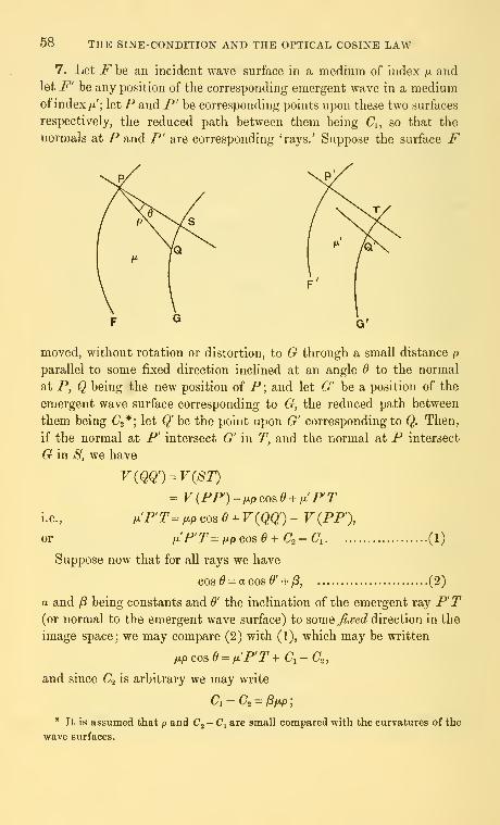
58 THE SINE-CONDITION AND THE OPTICAL COSINE LAW
7. Let F be an incident wave surface in a medium of index ;« andlet F' be any position of the corresponding emergent wave in a mediumofindex /a'; let/* and P' be corresponding points upon these two surfaces
respectively, the reduced path between them being (7,, so that the
normals at P and P' are corresponding 'rays.' Suppose the surface F
moved, without rotation or distortion, to G through a small distance p
parallel to some fixed direction inclined at an angle Q to the normal
at P, Q being the new position of P ; and let G' be a position of the
emergent wave surface corresponding to G, the reduced path between
them being C2*; let Q' be the point upon G' corresponding to Q. Then,
if the normal at P' intersect G' in T, and the normal at P intersect
G in B, we have
-F(PP')-WCOs^ + iLi'P'r
i.e., plP'T^ MP cos e + V{Qq) - V{PP'),
or iJi'P'T=f^pGose+C2-Ci (1)
Suppose now that for all rays we have
cos ^ = a cos ^' + y8, (2)
a and /8 being constants and 6' the inclination of the emergent ray P'T(or normal to the emergent wave surface) to some Jixed direction in the
image space; we may compare (2) with (1), which may be written
fi.pcose = ix'P'T+Ci-Co,
and since C^ is arbitrary we may write
Ci-(7, = /3/xp;
* It is assumed that p and C^ - C^ are small compared with the curvatures of the
wave surfaces.

THE SINE-CONDITION AND THE OPTICAL COSINE LAW 59
(2) is satisfied for all rays and we have
li'P'T = afxp COS 0'.
By the lemma of the preceding paragraph therefore the locus of T, i.e.,
the surface G', is merely a bodily displacement of the surface F', without
rotation or distortion, through a small distance p parallel to the fixed
direction in the image space; and
fx.'p' = afxp.
And inasmuch as a wave surface implies a corresponding caustic surface
we have the result
:
If two systems of corresponding rays, touching two caustic surfaces,
satisfy the condition cosO = a cos &' + ^, and 6' being the inclinations
of a ray to two fixed directions, the one in the object space and the other
in the image space, and a. and ft being constants, thsn corresponding to a
small displacement ofeither caustic surface, without rotation or distortion,
parallel to the fixed direction associated with it, there will be a small
displacement, wit/tout rotation or distortion, of the corresponding caustic
surface parallel to the other fixed direction; and, if the displacements be
respectively p and p in media of indices p. and p!, p-'p — a-p-p.
This result constitutes the 'optical cosine law' ; and it is to be noticed
that the fixed directions are any whatever, and not necessarily optically
corresponding ones. Moreover the general caustic surface is considered
so that the law contemplates the presence of any combination of the
geometrical aberrations ; and, further, it is not assumed that the optical
system is in any way symmetrical, for the only principle employed is
that of the 'reduced path.'
8. The optical cosine law gives as special cases a number of optical
results and we proceed to consider some of these.
(1) The Law of Refraction. Suppose that the optical system consist
of a single refracting surface and let the object caustic degenerate to a
point upon this surface ; then the image caustic will be the same point
and the two caustics may be made to undergo the same displace-
ment, viz., along the refracting surface. The cosine law gives for this
case
p! sin 6' = p.^va.9 + const.,
where 6 and 6' are the inclinations of a ray with the normal to the
refracting surface ; and the constant must vanish since the two rays,
incident and emergent, may coincide, without deviation, with the

60 THE SINE-CONDITION AND THE OPTICAL COSINE LAW
normal. We derive therefore the ordinary law of refraction; the law of
reflection follows in a similar way.
(2) The Sine- Condition. In a system symmetrical about an axis take
two axial and conjugate points, supposed free from aberration; the
two caustic surfaces reduce to these two points. Then if a slight motion
of one caustic (or point) perpendicular to the axis of the system implies
a motion of the other caustic—still remaining a point—also perpen-
dicular to the axis the system will be free from the first extra-axial
aberration, i.e., will be free from circular coma of all orders. And the
condition for this, from the cosine law, is
^ji'm sin ^' = /A sin ^ + const.,
6 and 0' being the inclination to the axis of a ray, before and after
refraction, and m the magnification ; again the constant must vanish
since 6 and 6' vanish together and we have the sine-condition of § 1.
(3) HerscheVs Condition. In (2) displacements perpendicular to the
axis of the system were considered ; take now an exactly similar case
but with small displacements along the axes. Then the object caustic
being a point the image caustic wiU remain a point, i.e., no aberrations
will be introduced provided that
cos 6' =a cos 6 + const.,
the ratio of the reduced displacements being a, so that by Maxwell's
elongation formula a = l/m^; and also ^ = and ^'=0 correspond, so
thatm^ (1 - cos ^') = 1 - cos 6
;
whence m sin 6'l2 = sin ^/2,
and we have Herschel's condition that the spherical aberration, supposed
zero for two conjugate axial points, should be stationary for small axial
displacements of these points.
(4) The Cosine Relations. If there be perfect definition for the con-
jugate planes at magnification m the object and image point caustics
must satisfy the cosine law for displacements parallel to the axes oft/
and z, and of y and z respectively, these axes being supposed parallel
as usual. The conditions therefore are
fiM- nifJi'M' = const., and fiN - mix'N' = const.,
L, M, N and L\ M', N' being the direction cosines of the ray in the
two spaces. The constants, of course, will be functions of the co-ordi-
nates but not of the direction cosines; we have, in fact, the cosine
elations of § 3.

THE COMPUTATION OF OPTICAL SYSTEMS 61
It will be observed that the cosine law is a generalisation of the sine-
condition and of Herschel's condition and that, unlike these conditions,
it is valid even in the presence of spherical aberration.
REFERENCES
Abbe. Archiv fiir mikroskopische Anatomie, ix, p. 40, 1873.
Clausius. Mechanische Wdrmetheone,
Helmholtz. Pogg. Annalen, Jubelband, 1874, p. 557.
Hockin. Journal of the Royal Microscopical Society, iv, p. 337, 1884.
Smith, T. The Optical Cosine Law. Trans. Opt. &'oc. xxiv (1922-3), No. 1.
Diet. App. Physics, Art. 'Optical Calculations.'
Steward, G. C. Phil. Trans. A, 225, Part ii, § 21.
Trans. Camb. Phil. Soc. xxiii. No. 9, § 10.
Proc. Camh. Phil. Soc. xxiii, vi, p. 703, ' On Herschel's Condition and the
Optical Cosine Law.'
CHAPTER VTHE COMPUTATION OF OPTICAL SYSTEMS
1. The Focal Eikonal for a Single Spherical Surface*. Hitherto
the performance of the general symmetrical optical system has been
considered and no specialisation has been made to particular systems;
indeed it has not been assumed for the most part that the component
surfaces are spherical ; but only that they are surfaces of revolution.
It has now to be seen how the preceding investigations may be linked
up with special systems and to this end two steps are necessary : the
aberration coefficients must be evaluated for a single surface, generally
spherical; and then addition formulae must be obtained which will
give the aberration coefficients of the whole system in terms of the
coefficients of the component single surfaces.
Let U be the reduced eikonal when the principal foci are taken as
base points; this is known as the 'reduced focal eikonal' and it is
evident that it is a constant of the system. Moreover if m - $ be the
customary eikonal the following relation holds
:
^-^-U+l^{l-L) + m{l-L'), (1)
the notation being as in the preceding chapters. The evaluation of U,
therefore, may be undertaken, instead of the evaluation of m - $. Thefirst application of this is to a single surface.
* Cf. Proc. Camb. Phil. Soc. xxiii, iv, 1926, p. 461.

62 THE COMPUTATION OF OPTICAL SYSTEMS
2. Let A be the pole and the centre of a spherical surface of radius
r and modified power J, separating media of indices /* and fi, and let
Fi and i^a he the principal foci of the surface : then
FiA= fj./K and ^i^a =/*'/'^>
where i^-if^' — 1^)1f-
Let PQP' be a ray whose direction cosines are L, M, N and L', M', N'respectively and let P and P' be the feet of the perpendiculars from
Fi and F^ ; let Q be upon the refracting surface. Let U be the focal
reduced eikonal; then if a constant be added to ensure the vanishing
of U for an axial ray
U^J{ii-{PQ-F,A) + fi:{QF-AF,)} (1)
Now PQ = L.FiO-rcosd and QP' ^ r cos 6' - L'. F^O,
where and B' are the angles of incidence and refraction ; so that
PQ = —, r cos and QP' = rcosd'+ ^n. — IJi /A — /u.
Substituting in (1)
U=^^^U' cosO' -,jiCose) + L+ L' ~ ^^' ~ ^^^ -2flfX IXfA.
^L^L'-^-!^^-2 (2)
Owing to the symmetry of the system this may be expressed in terms
of the variables a, b and c of Chapter n, § 6, viz.,
a = M' + N\ b = MM' + NN' and c = M'' + N'';
from which L= sl\-a and L' = Jl~ c.

THE COMPUTATION OF OPTICAL SYSTEMS 63
Then from (2) U' = ~(l+ vx)^ +L +L' --2,.V
.(3)
where/X/i
75 and x + '^{LL' + b-\) = 0.
This expression (3) may be expanded in terms of a, b and c, and the
coefficients of the various terms will involve simply the function v—an invariant of the system. For the consideration of the first order
aberrations only the second order terms need be taken, i.e.,
U=-b-l{v{a-2b + c)-+2ca} (4)-
3. The Aberration Coefficients. The focal eikonal has been evaluated
now for a single spherical surface ; that for a coaxial system of spherical
surfaces may be written
U=-b-l {A'a" - AB'ab + 2 (C+ ct) ac + 4(76^
-
4:Bbc + Ac% . . .(1)
together with terms of higher orders. The coefficients A, B, C, ra-, B'and A' are constants of the optical system, i.e., they are independent
of the particular conjugate planes to be chosen and also of the pupil
planes ; and these are the quantities which it is convenient to evaluate.
For, when they are known, simple relations will give the corresponding
values of the aberration coefficients o-j, o-g, o-j, 0-4, 0-5 and o-g in terms
of them ; because there will be a relation such as (1) § 1, i.e.,
u-^= U + -(lm ^L) + m(l-L) (2)
The right-hand side of this equation is a known function of the variables
a, b and c while the left-hand side is a function of a, /3 and y ; and wemay eliminate the former variables by means of the relations given in
Chapter 11, § 6. Since (2) is an identity we may equate coefficients andwe obtain the relations set out in the following scheme*
:

64 THE COMPUTATION OF OPTICAL SYSTEMS
For example,
a, = A -4m{B + l) + Gm'(iC+ z^/3) - Am' (B' +l) + m'A'
is a typical result. Instead of eliminating a, b and c and so obtaining
the o-'s in terms of ^, ... A', we may reverse the process and eliminate
a, ^ and y and obtain A, ... ^' in terms of the o-'s. In this way we
find that, when all the first order aberrations vanish, for the conjugate
planes at magnification m, the following relations must hold:
{A - m)/m' = B/m" ^ C/m^vjlO = B' = A'm- I ^-(s^ - m)l(s - mf.
Moreover it will be found that
a-z-VTi—'^is — mf,
so that -uj is the constant appearing in Chapter iii, § 6. But a simpler
method of evaluating vr is as follows : from the relations between the
variables a, b and c and a, ft and y we have
%Ta-|= = (-'»)'(sla-aT'> (^)
and applying this to relations (2) and (4) § 2
where now the aberration coefficients refer only to a single surface.
The curvature increment (P) (modified and reduced) produced by this
single surface is therefore unity, i.e.,
^(^)-^-<7y-'-^"where now p is the geometrical radius of curvature of the object (or
image) surface ; and the curvature increment produced by the system of
surfaces is
A(A) = 2/=2A = (J^^),n (4)
OT is the Petzval sum and the condition for flatness of field is
^Klfxix' = (5)
4. The Equation for the Addition of Aberrations. A general relation
is needed between the aberration coefficients for a combined system and
those for the several components and it is obtained as follows. Weconsider n coaxial systems, the reduced eikonal for system A, of modi-
fied power Jf^, being written (w-4>)x, the corresponding functions for
the combined system being written J^^ and (w-^)i,„. The base points
used are successively conjugate axial points for the several systems,

THE COMPUTATION OF OPTICAL SYSTEMS 65
the image point for system X. being the object point for system X+ 1.
Then using the figure and notation of §§ 5 and 6, Chapter ii, we have,
for the component A,
( —r- )= ^A - ^A = /
f^ds- ixds,
\ «/ /a JQk-1 Jok-1
Q^-i and Q\ being the feet of the perpendiculars upon the ray from the
conjugate base points O^-i and 0,,. Thus
.=i^gA-i \=iJo\-iA=l \ «/ /a
rQ'n
JQo JO) \ 'I /X,ra
since Q'x and Q^ and also 0\ and 0^ coincide for all values of A. Thus
we have the general equation for the addition of aberrations in the
form
(n.=i(vl «A result, of use subsequently, may be obtained here ; let two coaxial
systems, of modified powers J^ and J» and principal foci F^, F^ and F^,
F2, combine to form a system of modified power J and principal foci F, F'
(§ 12, Chapter i); and let P, P' and P" be three corresponding axial
points, i.e., P' is the image of P in the first system and P" that of P' in
the second sysetm, and let the corresponding magnifications be nii and
?»2 so that m (- m^ m^ is the magnification for the combined system.
Then
F'P" = F'F^ + f;P"
and, using the relations of § 12, Chapter i, we have
m^J— «/i- mJ^ = (2)
5. Addition of Aberration Coefficients. A direct application of this
has now to be made to the various aberration coefficients; two systems
may be considered and dashes used to distinguish them. Three sets of
variables a..., a' ..., a' ... may be defined as in Chapter 11, § 6, i.e.,
a (.9 - mf=^{M- sM'J + {N-sN")\ etc.,
a {s - mj = {M- s'3iy + (N- s'Wy, etc.,
a" (s" - m"y = {M' - s'M'J + {N' - s"N"y, etc.,
where capital letters are used to denote direction cosines, and

66 THE COMPUTATION OF OPTICAL SYSTEMS
a and a" refer to the single systems and a to the compound system
Also we havem-m'm" and s~s's" (1)
Now from the preceding paragraph the fundamental equation is
u~^ w'-4>' u" - ^"_ ^ /„>.
"7 T' J"~"^ ^^^
so that ^[^ J-/=^'
since the third term of (2) does not involve the variable M explicitly :
and to the first order this is
^{ulJ-u'IJ') = 0,
\ du dy 1 du dy _
Remembering now the first approximation to u, obtained in Chapter ii,
8 ^' ^^^-J 2mu = {s- my y,
this result is
1 (s-mf 2{M-mM") _ J^{s'-mj 2 {M- m'M') ^ ^
J 2m ' (s-my J' 2m' ' (s' -m'f'
M-mM" M-m'M' ,„sI.e., f
— = TTT— W' mJ mJ
Similarly we may differentiate (2) with respect to M' and obtain
a fu' u"\ -
to the first order; from which follows the relation
M- m'M' M'- m"M" ,,.
J,=
r,-jn— (4)J m J
Combining (3) and (4) we have
M- m'M' _ M'_-jn"M_^ _ M-mM", .
J' ~ m"J" ~ m"J '
^^
and a similar relation involving N, JV' and N" : we have also two
corresponding relations involving s, s' and s" in place of m, m and w".
Again, corresponding to (2) § 4 will be a relation involving s instead
of m., viz.
s'J-J'-sJ"^{i,

THE COMPUTATION OF OPTICAL SYSTEMS 67
and this, combined with (2) § 4, may be solved for the modified powers,
giving
/ J' J" J'
s-m sm" — s"m s" — m" m"s" (s - m')
'
Thus J^i^'-^^T _ {M-s3rj + (N-sN"T (J
.(6)
a" (s"
-
rnj {M' - s"M"f+ {N' - s'N'J \J"
i.e., a = a" from (5) and (6). Similarly
a{s- my _ {M- sM'J +(N- sN'J _ fs"Jya (s' - mj (iM- s'MJ + {N-s'NJ \ J'
so that a' = m"' a. In the same way we have the relations
/3 = f3",y = y", (i'^s"m"f3 and y' = s"^y (7)
6. Let us consider now the equation for the addition of aberrations
(1) §4; It IS
^^_^-^iJ_^^_^yiJ>_^^_^yiJ"^Q. ^j>)
the u& are functions only of the y's, which will /ary slightly with the
introduction of aberrations ; the first approximations are given in § 5.
If we write , , t >, t> ,>, m /^^ = ulJ-ujJ -u jJ', (2j
then, by using (6) and (7) §5, combined with the expansion for u, it is
seen that the first and second order terms in ^ vanish identically.
Moreover the variation of * brought about by the introduction of aberra-
tions is given by
8^ oc m" (831- mUI") - m" {UI- mUI') - m {UF - m"8M")
+ m" {m - mm") - m" (8N - m'm') - m {IN' - m'lN")
i.e., 8* = 0,
as far as terms involving y^. So far, therefore, as second order aberrations
are concerned (1) reduces to
^IJ-^'IJ'-^"IJ" = 0, (3)
which accordingly may be used to give the addition formulae for the
primary aberrations.
In conformity with the notation of Chapter iii, § 3, we may write
8$ = o-ja- —ianaft + 2cr^ay + 4,(7^/3' — A(Tr,(3y + o-gy^;
substituting therefore in (3), and using (7) § 5, we may equate coefficients,
since (3) is an identity, and obtain
(?) =(5) «=»-(?);. GO ^(7')»'»•=
n'?)'
7)=(j)''""»""(5V \jj-\j.

68 THE COMPUTATION OF OPTICAL SYSTEMS
These results may clearly be extended to a composite system formed
by combining n systems—which as a special case may themselves be
simple surfaces; then if nip^q denote the magnification for the combined
systems from p to g inclusive, and the like for Sp^q, the general formulae
for the addition of aberrations follow, viz.,
(7).,.=A(7i—^-- (jL^K?)/'--*From this result, therefore, the optical properties of a complete system
may be written down at once from a knowledge of the corresponding
properties of the several components of the system, as far as first order
aberrations are concerned.
7. Formulaefor Aberration Coefficients. Let us now consider a single
spherical surface for which the focal eikonal is given in § 2; as in § 1 we
have the relation
w-<D= U + (\ ~ L)lm + {I - L')m, (1)
in which the left-hand side is a function of the variables a, /3 and y and
the right-hand side of the variables a, b and c; and linear relations exist
between these variables, given in Chapter ii, §6. (1) is an identity and
we may therefore substitute either set of variables in terms of the other
set and equate the coefficients of the corresponding powers. Let us
eliminate a, b and c ; then remembering the form of <E> and making use
of the expansion of u in terms of y we have
o-j = (w - 1)^ {v {ih — 1)^ - m\,
(T^-{in~ l)(s- \){v{m— \y-m\,
<Tz = v{m- \f (s - ly + (m-l)(m — s^)
o-i = (s- ly {v (m — 1)- - m},
o-5 = 'y (m -1) {s-iy + {s- l){m — sr),
and (Te = (s-iy{v{s-iy~s\; (2)
where the suffix X may be attached to each quantity since these relations
refer to the surface A.. Moreover
»2AW2A + l,n = ^A.,n ^ud Wa + i ,„ Ji , „ = Jj, X + W2 A+1 ,» J •••(3)
* Of. also Proc. Camb. Phil. Soc. xxiii, v, p. 584.

THE COMPUTATION OF OPTICAL SYSTEMS 69
and similar relations hold involving s. Here m denotes the magnification
for the combined system. On substitution in the first of (2) we have
...(4)
Now if we write m = in the table of § 3, it appears that o-j = ^ ; so that,
on making use of the addition formulae of § 6, we have
Again on writing w = in the table of § 3 it is seen that a-o + sB = A ; so
that we may evaluate the coefficient B, and similarly the remaining
coefficients, obtaining results corresponding to (5). The most useful case
is that in which the end media are air, of refractive index unity; and
then expressing the formula (5) in terms of the ordinary powers we
have
K',.U ^ i ^fA (^. _^) Um.'Ji^-K.X (6)
using the results given in Chapter i, § 9 ; here ^^ is the curvature of
surface A. The results may be expressed concisely as follows ; let
T7-Z h _ -^ i.p -"- l.p-1 v-z ;,' _ J^p.n -Q-p-4-l.it
then
I*- p H- p-i M p-i f^'p
dicp
T - U. 7? -^i? /r t' - n 7? ^^P-»I /T•f-p — f^pj-t'p
p.— -n.i_p, cO p — fj.p xvp •i-j\.p +in,
3^1.
A
n K ;- . „' ^^UK rr I y >. ^^i.A
A-l ^'^X A = l <^K\ A = l S^A
C= 2A:\^/4^, B'^^]c\x,x,-^, A'=^k\x\^^,A = l O'^A X= l OK^ x = l OK^
n
^i,™^i,7i = 2 KjfX),_ifj.^ (7)
These summations may be calculated readily for they involve quantities
similar to those used in Chapter i to obtain the power of the combinedsystem; and when ^, ^, ... J.' are known—being constants for a given
system—the aberration coefficients o-j, ... o-g may be obtained from the
table of § 3. These will then give the first order aberrations for anyconjugate planes and any exit-pupil.

70 THE COMPUTATION OF OPTICAL SYSTEMS
As a check upon the result (4) § 3 we have from (2)* above
0-3-0-4 Ji
n
A = l
- J l,n 2 J\\J'^\,n — ^ 2 «/x,J.—
. i'A/«'i,re T —
'
A = l «'l)reA = ln
i.e., (Jot)j^„= 2 Ja.A = l
Or, if the end media be air,n
A= l
8. Aberrations at the Principal Foci. The formulae of the preceding
paragraph give completely the primary aberrations of an optical system
—
or rather they give the constants ^ , . . .^' in terms of which the aberration
coefficients are known. The quantities involved in the formulae are the
same as occur in the formulae of Chapter i, so that very little additional
work is necessary for their calculation ; and in fact with a machine their
computation is quite rapid. The aberrations of higher orders may be
dealt with similarly but they are beyond the scope of this tract. For
these reference may be made to a paper by T. Smith t. Similar formulae
may be found for them involving again the same quantities and their
computation may be carried out in the same way.
It will be observed that if we write m = we are dealing with the
second principal focus and we have from § 3
0-1 = A, (T2~ A- sB, (1)
i.e., a-2 = A - B,
if s = 1 and the exit-pupil is at the second unit plane ; this very com-
monly is the case. Thus ^ = implies the absence of spherical aberration
at the second principal focus while if, in addition, ^ = first order comaalso
has been eliminated, i.e., the condition5=0 implies the satisfaction of the
sine-condition for the second principal focus, to this order ofapproximation.
In the case of thin systems s=l implies that the pupil-planes coincide
with the boundary of the optical surfaces ; but here special relations hold
between the six constants A, ... A'.
* By the application of the results (2) of this paragraph it may be verified that
the various forms of conditions commonly given are at once deducible from the
formulae of Chapter in : e.g. Whittaker, Camb. Math. Tract, No. 7.
I 'The Addition of Aberrations,' T. Smith, Trans. Opt. Soc. xxv, No. 4.

THE COMPUTATION OF OPTICAL SYSTEMS 71
9. Thin Systems. Inpractice ' thin' systems will not occur but cases arise
in which the properties of a system may be investigated with some
accuracy by regarding it as thin. And here the constants A, ...A' will
not be independent; we propose to find the relations between them.
Without loss of generality we may write K^,,,- 1 and then
n n n n
-^ —- -^ iCp OCp ^ -O —^ 2i Kp OOp tjCp)O — -^ itp OCp —- *^ li'p JCp
y11 11n n n
and ^ ' = 2 ^-Jxp"^, B' = 1. kp'xp Xp, ot = 2 Hpji^p-i i^p \
1 1 1
where Jcp = f^/? - ^'--K") , h' = f^ - ^^) ,
\ p-p' t^p-i' / \H-p-i f^p /
and .Tp =/j.pEp- Ki^p, Xp = fj^p Rp + Kp+x „
.
Thusn n
A — 2B + C=1kp (xp- — 2xpXp' + Xp") - 2 kp (xp - Xp'y
— 2 kp (a1 ,p +A p+i ^
„)" — 2 kp1 1
=^ (')
Similarly A'-2B'+C =\ (2)
And
B + B'-2C='^ {kpXr, - kpXp) = ^ \xp( ^"2 )
" ^p [1 1 I \H-p-i H-p / )
= 2k^J-^-A)--^J-2 "^
1 t \/*p-i Mp / H-p-i) 1 /^p-i^p
= w (3)
Thus if the end media be air we have the relations
A + C = 2B + l]
B + B' = 2C+x^[
; (4)
A' + C=2B'+l]so that for a thin system three only of the constants need be evaluated.
REFERENCESSmith, T. Dictionary of Applied Physics, Art. ' Optical Calculations.'
Trans. Opt. Soc. xviii, 1917.
Collected Researches of the National Phys. Lab. vols, xvi, xvii.
Steward, G. C. Phil. Trans. Roy. Soc. A, 225, 1925, Part i.
Proc. Camb. Phil. Soc. xxiii. Part iv, p. 461.
Proc. Camb. Phil. Soc. xxiii. Part v, p. 584.
' On Invariant and Semi-Invariant Aberrations of the Symmetrical Optical
System.' Acta Math. vol. 67 (1936).

72 DIFFRACTION PATTERNS ASSOCIATED WITH
CHAPTEE VI
DIFFRACTION PATTERNS ASSOCIATED WITHTHE SYMMETRICAL OPTICAL SYSTEM
1. General Formulae. The preceding discussion of the working of the
symmetrical optical system has been purely geometrical in character
and it has been assumed that the only requisite for a point image is that
the emergent rays should themselves pass through a point. But owing
to the physical nature of light and to its finite, though small, wave-length
this assumption is untenable; for a part only of the complete incident
wave will pass through the system, and for this reason diffraction pheno-
mena will appear ; so that corresponding to a point source of light there
will in no case be a point image but, instead, a diffraction pattern. Andthis diffraction pattern will be modified profoundly by the presence of
the geometrical aberrations which have been considered in the preceding
chapters. In the absence of these aberrations, i.e., if we assume perfect
definition for two conjugate planes, the ideal diffraction pattern is a
series of concentric circles, alternately bright and dark, with centre at
the conjugate point; this was investigated by Airy in 1834. We desire
to examine this pattern and, in particular, the modification of it pro-
duced by the geometrical aberrations of the system.
The general method of procedure, as is usual in discussions of diffrac-
tion phenomena, is to apply Huyghens' Principle; which enables us to
determine the effect, at a given point, of any propagated disturbance,
when a surface surrounding the point can be taken, the secondary
surface, over which the disturbance is known. It is assumed that each
element of this secondary surface originates a disturbance, the phase
and amplitude of which are appropriate to the element considered.
2. The emergent wave is limited as to size and shape by the exit-
pupil of the system and we may take this as the secondary surface, the
disturbance over which produces the diffraction effects; and by integra-
ting over this surface the diffraction pattern may be obtained.
Let AA' be the axis of a symmetrical optical system and let 0, 0'
Q Ti
Pi
O' A'

THE SYMMETRICAL OPTICAL SYSTEM 73
and E, E' be pairs of conjugate axial points. Let a ray cut the normal
planes through 0, E and E' in P, Q and Q' respectively, and let Pj
upon the normal plane 0' be the Gaussian conjugate of P; the planes
E and E' will be taken as the pupil planes of the system. In conformity
with the preceding notation the co-ordinates of P and Q' may be taken
to be Y, Z and /, z, and those of Pi, Y^, Zi. Let
= / fji-ds,
so that Fis the characteristic function, and 27r F/A is the phase difference
between the luminous vibrations at the points P and Q'; where A. is the
wave-length of the disturbance measured in vacuo or, of course, the
reduced length measured in any medium. The phase contribution of
the element dS of the exit-pupil at Q' to the disturbance at a point T^
upon the normal plane through 0' and near to Pi is
27r(F + r-H^)/\*,
where Q'Tj=r; so that the intensity of the disturbance at Ti is pro-
portional to the squared modulus of the expression
e d8\ (1)
The amplitude of the vibration has been omitted and this is justified
by the consideration that 7\ is near to Pi and the emergent wave sur-
faces are approximately concentric spheres with centre at Pj , so that the
amplitude enters as a factor of the form ^/r, where yl is a constant and r,
to the first order, is equal to the distance between the planes E' and 0'
.
3. Now the function F depends only upon the variables B, <^ and \^
and the variables of integration over the pupil planes arey' and z: so that
^ is a constant as far as this integration is concerned. Moreover we have
F=/(^)-^n/iT^ + P, (1)
where F is the aberration function. Let p', ^' be the polar co-ordinates
of Ti referred to parallel axes through Pi and let p, ^x be the polar
co-ordinates of Q' upon the exit-pupil: then if E'O' = d
r^ = <^^ -I- ( Fi + p' cos ^ — p cos ^i)^ -f- (Zi + p' sin <^' - p sin ^i)^
i.e., r = c? vl -I- ?^ + a,
if we write Zx = 0, where
ad>^ = 2p' Fi cos(f>'- 2pp' cos (^i
-<t>') + p'^ and u-6 -<f> + i{/:
* Rayleigh, Sci. Papers, vol. iii, p. 74.
•fWe must take X and r to be modified distances, i.e., distances multiplied by the
modified power of the optical system : cf. p. 27, footnote.

74 DIFFRACTION PATTERNS ASSOCIATED WITH
and p is small so that to a first approximation we have from (1)
F+r=/(6) + ^cos <^'-^' cos (.^i-f) + -^- (2)
The light intensity is required not only at neighbouring points upon
the normal plane O'Pi but also at near points upon neighbouring planes
;
for we have to consider the effect of change of focus. We may consider
a normal plane distant X from 0\ measured positively in the direction
0'E\ where X will be small; this is equivalent to writing {d —X) in
place of d above and the additional terms obtained are therefore
-X+^(F,^-2pF,cosc^,+A (3)
to the first approximation. Thus, finally, we have
V + r = constant + *,
where ^ = i^- {fip\d) cos (<^i- <^') +
^^,- (p^ - 2p Fj cos <^i), (4)
and the terms not involving the variables of integration p, <^i are absorbed
in the constant. Eemembering that a constant real term in (4) does not
affect the modulus of (1) §2, that result becomes
e"" d^, (5)
where kX= 27r. The squared modulus of this is proportional to the light
intensity; if therefore we consider the value of (5) at the Gaussian
image Pj and in the absence of aberrations, i.e., F= 0, p' = and X=0and therefore * = 0, we have simply
/\̂dS=B,
where 8 is the area of the exit-pupil. The result
(6)-^ \e'^ dS
gives therefore the light intensity at ani/ point T^, in the neighbourhood
of Pi, relative to the intensity at Pi for an aberrationless system, i.e.,
this intensity is taken as unity. The expression (6) is therefore the
general result covering the case of exit-pupils of any form; in the
present chapter we shall assume that the exit-pupil is circular with
centre upon the axis of the system.
4. The co-ordinates of T^ relative to Pi as origin are p', <^'; it is con-
venient to use a slight modification of these and to introduce a new

THE SYMMETRICAL OPTICAL SYSTEM 75
co-ordinate, the meaning of which is considered here. Let S be the
exit-pupil with centre B' and radius pi, and let P be a point upon a
plane normal to and intersecting the axis of the system in 0', where
EV = d; let AB be the diameter of S parallel to OF and let OP = Y,
.
Then if Yi and pi be small compared with d we have approximately
AP~BP = 2YiPi/d, so that the difference in phase at P between rays
S
Pi\b

Jo Jo
2n _,'^eos(.J.-*') ,, 1
76 DIFFRACTION PATTERNS ASSOCIATED WITH
pattern, i.e., in (4) §3 we write F^O and X = and so consider the
light effect upon the conjugate plane in the absence of geometrical
aberrations. Here
'^* = -^cos(<^i-<^'),
so that we must consider the expression
where Jo (t) is the Bessel function of order zero
;
so that n/7= % f\jo(t)dt = 2J,(z)/z (1)z Jo
The intensity depends only upon z and the light contours (lines of
equal intensity) are therefore circles with the point Pi as centre; the
central intensity is of course taken as unity and we have therefore dark
rings of zero intensity at the values of z given by the roots of the
equation
«^i(-) = 0, (2)
other than 2;=0 ; while the maxima are given by the roots of the equation
in z
i.e., J,{z) = (3)
li z^Zi be a root of (2) or (3) the radius p of the corresponding
dark or bright ring is given by
ti-rrpip' = ZiXd,
so that the radii of the rings vary directly as the wave-length of the
luminous vibration considered and inversely as the radius of the exit-
pupil : the diffraction pattern therefore will commonly be coloured and
we shall obtain zero intensities only if monochromatic light be used
—
or if the pattern be viewed through a colour filter.
It is of interest to investigate the proportion of the total intensity in
the various rings, and to this end we must evaluate the expression
i~~Izdz=4. rJi'{z).z-'dzJo Jo
= 2{l-Jo\z)-J,\z)].
In general, therefore, the fraction of the illumination to be found
outside any ring of radius z is

THE SYMMETRICAL OPTICAL SYSTEM 77
SO that the fraction outside any dark ring is simply J^{z). From this
it appears that more than 90% of the illumination is concentrated
within the area of the second dark ring.
For large values of z we have
Z Z\ TTZ
SO that the maxima and minima occur at equal intervals ; moreover the
mean brightness varies as 1/z^*.
6. Change of Focus and Spherical Aberration. We wish to examine
the effect of axial aberrations and we write Fi = in (4) § 3 ; so that
*<* =—^ cos (<^i -</>) + -^^ +kF,
and F now will contain only terms in the variable x}/ or (p/df. If now
Kpp' = td, KXp-^2ix.t''d\ KA„^o,sp'^ = Vst''d^,
we have k* = - ^cos (<^i- ^') + ;otr^+ 2 v^f* (1)4 = 2
The quantity /u. governs change of focus, v^ governs spherical aberra-
tion of order s~l, so that (1) is the general expression required; and
substituting directly in (6) § 3 we have the intensity given by
Jl- I e''''Jo(z\/t)dtJo
.(2)
if we neglect aberrations. This expression therefore gives the intensity
of illumination at any point of the neighbouring plane Jl; it will be
seen that the co-ordinate <^i does not appear, so that the diffraction
pattern is again a system of concentric circles. The general effect is
shewn in the diagram and it is evident that there is a diminution of
central intensity. If we adopt the Rayleigh limit, i.e., if we assume that
a twenty per cent, loss in central intensity is allowable, we may find
the corresponding change of focus permissible. But before this we mayconsider the extension of (2) to cover the presence of all orders of axial
aberration ; clearly it is
.(3)JI=\I
e"''^'^"'' J,{zJt)dtI-'0
so that in this case also the diffraction pattern is a series of concentric
circles.
Equation (2) may be evaluated by expansion in a series of Bessel
functions and two series are obtained—one useful for large values of z
* Rayleigh, Sci. Papers, vol. in, p. 91.

78 DIFFRACTION PATTERNS ASSOCIATED WITH
and the other for small values*. These series are known as Lommel
Functions—named after Lommel, who discussed them at some length.
The equation (3) may be evaluated in the same way and this gives
rise to 'generalised Lommel Functions' which have been discussed in
a paper by the author!; to consider them here would be beyond the
limits of this tract.
7. The Axial Intensity. It is of importance to find the axial variation
of intensity; we write z = in (3) § 6 and we have to consider the
expression
where /^ = 2Trn, v^ = 27rWs and n^ is the number of wave-lengths excess
of aberration of order s, n denoting in the same way the change of
focussing plane. If v^ = we have
p "iiriut _ 1
/:e'>^' dt =
"I-rnn
H^'J wso that there are dark points along the axis given by integral values of w:
moreover by writing n = l vfe have /="81 approximately, so that in
accordance with the Kayleigh limit one-quarter of a wave-length change
of focus is the utmost that can be allowed.
Taking into account now first order aberration we obtain the ex-
pression
Jo 27rw Jo
SO that by change of variable
V7=-Vf'"' e'dtl (2)
and the value of this may be read off at once from tables of Fresnel's
integrals. It follows immediately from this result, by writing n + ni = ±S,
that the axial intensity is symmetrical about the point given by n + /?i =
and this from § 4 is the mid-point of the longitudinal aberration ; for the
marginal focus is given by w + 2wi =0. This maybe contrasted with the
* E. Lommel, Ahh. d. k. Bayer. Akad. vol. xv, 1886. Cf. also Gray and Mathews,
Bessel Functions, chap. xiv.
t 'Aberration Diffraction Effects,' Phil. Trans. Roy. Soc. A, 225.

THE SYMMETRICAL OPTICAL SYSTEM 79
result of the geometrical theory § 4, Chapter iii, according to which the
best focussing position is at a point of quadrisection of the longitudinal
aberration and not as we see now at the centre.
If Wi = 1 we have from (2) and tables of Fresnel's integrals the
following
:
%= : -| : -1 : -3: _2 : -3
/= 0-0891 : 0-3650 : 0-8003 : 0-3650 : 0-0891 : 0-0084
The intensity, therefore, at the paraxial focus falls to about 0"09 while
if change of focus be admissible, to w + 1 = 0, the intensity rises to 0"80;
and this illustrates the beneficial effect of change of focus. There are nowno dark points upon the axis.
I = Airy Disc
ir=Out of-focus Plane{n = i/tt)
Iir= Gaussian Image Plane(first-order aberration n^ = i/tt)

80 DIFFRACTION PATTERNS ASSOCIATED WITH
We may study in a similar way the effect of higher order aberrations;
for taking account only of the first two orders it is usual to design a
lens so that the paraxial and marginal foci coincide. It may be verified
that with 2?2o = 1 the maximum intensity is about '87 so that only a little
more than half a wave-length of second order aberration can be admitted
;
but this is in the absence of first order aberration; in the presence ot
the latter as much as four wave-lengths of the second order aberration
may be tolerated.
The diagram given shews the light distribu tion in the three cases marked;
in each case a half-section is shewn passing through the centre of the
system of contours ; the general effect is seen to be to scatter the light
into the outer parts of the field.
8. Comatic Patterns. In order to consider the efi"ect of coma of the
first order we must take into account the term in ^i/' in the function i^so
that in § 3 we write
^ = 2^5 (q) i^-j) cos </>! + ^, (p'-2p Ficos <^i)-^^ cos (</>! - <^'),
i.e., K* = )iiv-i- (7cos(<^i -i/'), (1)
where G cos \li=^ A — z Jv cos <^', C am^^-z Jv sin ^',
and A^^Jv^-€s/v,
so that C'-^A"^- 2Az Jv cos ^' + z^v.
Also
zdJ'o^K-pp, zd=Kpip', pd*=2Ka5pi^ Fi, ed^=KXpi Yi and 2p-d^=KXpT^.
In this case the integral which we must consider is
l\'''Vo(C)dv, (2).'0
where C' - (I3v - e)-v - 2zv (fiv - c) cos <^' + z'^v. This integral reduces to
unity if/8 = ;s = € = 0so that the squared modulus of (2) will give us the
light intensity in the presence of coma. If we consider in the first place
the axis FiC, §5, Chapter iii, of the coma figure, i.e., write ^'=-0, we
have
e**"Vo (^'^^ -Z + e Jv) dv,t
i.e., fe''^'Jo(/3vi-zv^')dv, (3)Jo
where the origin of z has been changed ; and it is clear that a change
in the sign of /* leaves unaltered the modulus of (3). Thus nothing is to
be gained by 'change of focus' with the coma-type of aberrations and

THE SYMMETRICAL OPTICAL SYSTEM 81
this property is common to all the coma-type. We may therefore write
/A = and consider only the effect upon the Gaussian plane— in which
case (1) becomes
Jl= f J^ ( Jz-'v - 2zPv^ cos <l>'+ ;8V) dv (4)
Jo
It will be seen that fid^Kp^P^ G, § 5, Chapter iii, so that /8 is the measure
of PiG in the wave-length co-ordinates. The preceding integral may be
evaluated by expansion in an infinite series of Bessel functions and in
fact two series may be obtained suitable for various values of z, the one
for the outer parts of the field and the other for the inner parts. More-
Ov^er the light contours may be drawn, i.e., the curves of constant
intensity, by writing _JI = const.
in (4). But these expansions are beyond the scope of this tract*.
9. It is important to find the intensity upon the axis of the coma
figure, i.e., when </)' = 0; we have
JJ= I J,{l3ji^-zJv)dv, (1)J
See Phil. Trans. Roy. Soc. A, 225.

82 DIFFRACTION PATTERNS ASSOCIATED WITH
and here z may carry its own sign so as to cover the case of the line
^' = TT. Dark points occur therefore upon the axis of the figure, and their
positions are given by the roots of the equation in s,
/Jo{l^slv'-zsJv)dv = 0\ ...(2)
and the positions of the turning values of the intensity are given by the
roots of the equation in z,
J,{Pv-zJv')dv = 0; (3)/:
and these in general will be the maxima of the intensity*.
It is of interest to examine some numerical results ; thus let )8 = 4,
then it will be found that the 'central' root of (3) is very nearly z = 2/3/3
and that the intensity there is approximately '80 ; the amount of comatherefore represented by /8 = 4 brings us to the Rayleigh limit. Moreover
the central intensity has shifted from the conjugate point, towards
the head of the coma figure ; and as the amount of coma increases this
central intensity point moves relatively towards the head of the figure
;
e.g., when /?= 12 it is very nearly midway between Pj and G.
If ^ = 4 the central contours are very nearly circular but the outer
contours are elongated in the negative direction of the axis of the coma
figure ; and for larger values of ft they depart very much more from the
circular shape; moreover the intensities in one direction are very much
greater than those in the opposite direction, and this produces the well-
known 'comet' appearance associated with coma. The general conclusion
may be drawn that there is no similarity whatever between the actual
(diffraction) coma figure and that indicated by geometrical theory. Onthe other hand if z//3 be large the figure approximates to the Airy disc.
Approximate roots of the equation (2) if /8 = 4 are «= 114, 77, 27,
— 77. The radius of the first light 'ring' is therefore 10 '4 in the direc-
tion PiG, and 5 in the opposite direction; while in the Airy disc it
is 5'1 in either direction. The distortion effect of coma is thus very
marked upon the first bright 'ring.' The radii of the first dark 'ring' are
respectively 9'2 and 3"3, compared with the Airy disc 3*3; while those
of the second 'ring' are 12 and 7 compared with 7. These results shew
the central distortion which tends to disappear in the outer parts of
the field.
It is useful to interpret these results in terms of the departure from
the sine-condition : let the paraxial magnification produced by an optical
* See Phil. Tram. Roy. Soc. A, 225.
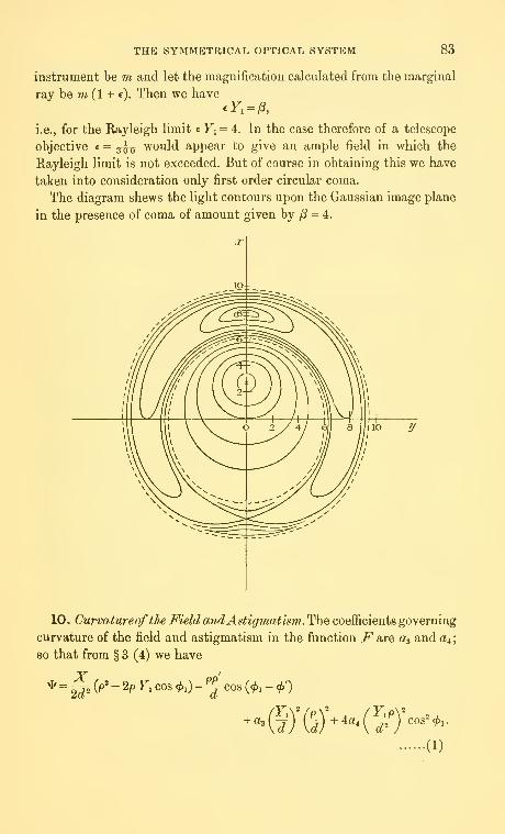
THE SYMMETRICAL OPTICAL SYSTEM 83
instrument be m and let the magnification calculated from the marginal
ray be m (1 + e). Then we have
i.e., for the Rayleigh limit € Fj = 4. In the case therefore of a telescope
objective c = ^^^ would appear to give an ample field in which the
Rayleigh limit is not exceeded. But of course in obtaining this we have
taken into consideration only first order circular coma.
The diagram shews the light contours upon the Gaussian image plane
in the presence of coma of amount given by /S = 4.
10, CtJt/rvatureofthe Field andAstigmatism. The coefficients governing
curvature of the field and astigmatism in the function i^are a^ and a^;
so that from § 3 (4) we have
X pp
(1)

84 DIFFRACTION PATTERNS ASSOCIATED WITH
If a4 = the two surfaces coincide and we are dealing simply with
curvature of the field and the terms in (1) may be written
^(x+2».^)-f cos (*,-*) (2)
where C cos ^= X~ + p cos <^' and C sin i/' = p sin 4>'- Now this is of
the same form as § 6, so that we are led again to the same expression as
that obtained for simple out-of-focus effects. Moreover if we write
we have Jl=\ pdp j e **d*'°^ ^ c?<^^
-m4)/'¥' wi.e., the Airy disc; and C measures the distance of the point under
consideration from the central line of §2, Chapter in. The receiving
plane in this position will pass through the point of intersection of the
central line with the curved image surface : and in any case we have the
law of intensity variation along this central line—and indeed in normal
planes—as in § 7. We have therefore the general result ; for varying
positions of the receiving planeX the diffraction pattern will always be
a ring system whose centre is upon the central line and for one particular
plane this central intensity will be unity—i.e., we have the Airy disc.
It is interesting to interpret these results in terms of the Petzval sum nr
in order to discover what value of ra- is permissible. As above, however,
if one object only be present (a star in the case of a telescopic system),
then a suitable change of focus will always give the Airy disc ; but if
several stars be in the field of view, to be examined simultaneously, then
unlimited change of focus is notallowable. For one stardisc will satisfy the
Rayleigh limit for one set of positions of the plane X, another for another
set, and so on, and that value of ot is required which will bring within the
Rayleigh limit all the star discs for at least one position of the plane.
As in § 7 the wave-length change of focus allowable from the Airy
disc is n-l; and since here ^3 = W" and 2FP
-
C7 Yj^ (§ 6, Chapter iii)
the limit will be satisfied provided
2d'' ~2 -^ 2'
iroo /'dV2TrI.e., otFi-> (- — ,
i.e., ^IV^C^Va, (4)\pi/
X being the wave-length of the luminous vibration considered.

THE SYMMETRICAL OPTICAL SYSTEM 85
The focussing plane is movable, and this admits a value of ot twice
as large as that indicated by (4) ; so that taking a numerical example
in which d = 30pi and XjJ = 0'0006 mm. if Yi/J= 2 '5 cm, we have from
(4), as the limiting value of nx,
Jz!T = -0009,
where J is the modified power of the system. And this may be doubled
as above.
11. In the general case, i.e., if a^ =¥ 0, astigmatism is present and wehave (1) §10: the resulting expressions admit of general integration
but reference must be made to the paper quoted before* : some immediate
specialisations of considerable importance however may be made. For
example
:
(1) the integrals are unaffected by a change in the sign of<i>', so
that the resulting light contours are symmetrical about the line <f>'= 0;
(2) they are unaffected by the addition of tt to if/; the origin is
therefore a centre of symmetry of the contours
;
(3) on differentiation with respect to ^, and putting \j/=0, it
becomes evident that the contours cut the line i/^ = at right angles.
It is of importance to examine the intensity distribution along the
central line. The general expression to be considered is
J= pe^ dpi e- 'd4>i, (1).^ -'
upon the central line, since here C^O; where
2yp=' d^ = Kp' {X+^' (^3 + Aa,)\ and ftd' = - Aa.Kp^ Fl^
Thus yp^ =g {X + '^ (a, + 2a.)} + 2a.'-^ = Tp^ - /3l2,
where r measures the separation of the focussing plane from the mid-
point of the astigmatic separation. Then
J-=\ pe dp e a^i = 2ir/ pe Jo{oip") dp,Jo Jo J
where yS= 2ap^; i.e.,
c/=7r I / ^Jf,(au) du,J
by change of variable. The intensity at the image point in the absence
of aberrations must be unity, so that the expression whose squared
modulus gives this intensity is
—2Jj«'^"«^o(««)<^w ^^^
* Phil. Trans. Roy. Soc. A, 225.

86 DIFFRACTION PATTERNS ASSOCIATED WITH
If now n be the number of wave-length units of astigmatism
2api2 = 27rw = 2/x (say),
and if n^ measure the distance from the mid-point of the astigmatic
separation
Tp/ = 2irwi = X (say),
and (2) becomes
(\'^'Jo(tit)dt, (3)J
and this is the general expression whose squared modulus gives the
intensity distribution along the central line—which evidently depends
upon the difference between the curvatures of the two focal surfaces.
12. We consider some particular cases of (3) § 11.
(1) Let fi = 0, i.e., let the system be free from astigmatism, but
not necessarily from curvature of the field; we have
/
1
e'^'^dt,
leading at once to the case of (1) § 7.
(2) Let X = 0, i.e., consider the intensity at the mid-poiat of the
astigmatic separation; we have
j J,(,jit)dt.J
Now / JJl'2t)dt^0-8d, so that in this case /=079: the quantityJ
of astigmatism represented therefore by /t = 1 "2 brings us to the Rayleigh
limit for the mid-point. As a typical case let d = 30pi (in a telescope),
then the astigmatic separation is given by
2XFiF2 =^ (30)^ 24 = 041 mm. approximately.
27r
(3) Let X + ju.= 0, i.e., consider the intensity at either of the foci
Fi and F^ : we have
/V''^Vo(/xO<^^,
so that the intensities at the foci are equal ; indeed, since in (3) § 1
1
a change in sign of X leaves unaltered the modulus of the integral,
the intensities are symmetrical about the mid-point of the astigmatic
separation.
For the light contours and a more complete examination of the effects
of astigmatism upon the dififraction pattern produced we must refer to
the paper mentioned above.

THE SYMMETRICAL OPTICAL SYSTEM 87
13. Distortion. If all the aberration coefficients vanish except a^ weare dealing with distortion, so that from (4) § 3 we have
*= ^^ ^^' ~ ^^ ^' ^°' ^'^ ~ J '''' ^'^' ~ '^'^ ^ ^""^ (ji) ~d^ ^""^ *^'
'
(1)
and if, in the first place, we write X-0 and consider only the paraxial
image plane we have
* = ^cos(«^.-V), (2)
where C cos i/^ = -J F/ - p cos <^', C sin i/^ = - p' sin <^',
so that (7=(^^F,^y-2p'cos<^'(^^F.«)+p- (3)
From this last result it is evident that C measures the distance from
the new (distortion) image point of § 7, Chapter iii; and then from (2)
we have
s/I=—; \pdpl e
'^d<f>,,
'rpi Jo Jo
-^=2^^^, (4)
d
and accordingly we have the Airy disc with centre at the new distortion
image point; the effect of distortion therefore is merely to move the
ideal diffraction pattern as a whole through a distance equal and parallel
to the geometrical distortion.
The general case for out-of-focus planes may be obtained directly
from (1) ; for we have
*4(3y-^'-^(*--« (^)
where C is given by the relation (3) if for the terms in the brackets be
-~ Fi' -X -T^ j . We are led again to the ordinary ex-
pression for out-of-focus effects—giving rise to Lommel functions. More-'
over the centre of the diffraction pattern is upon the central line of
the system ; and the expression whose squared modulus gives the light
intensity is
where kJCpi^ - Atrnd^ and Kp^C = zd.
* Phil. Trans. Roy. Soc. A, 225, p. 198.

88 VARIOUS FORMS OF APERTURE
REFERENCES
Airy. Trans. Camh. Phil. Soc. (1834), No. 283.
Trans. Camh. Phil. Soc. (1838).
Phil. Mag. 1841.
Andr^. Ann. d. I'Acole Normale Sup. No. 5 (1876), No. 10 (1881).
Buxton, A. Monthly Notices R. A. S. Lxxxi, 8 (1921).
Monthly Notices R. A. S. Lxxxiii, 8 (1923).
Conrady, A. E. Monthly Notices R. A. S. lxxix, 8 (1919).
Lommel. Abh. d. k. Bayer. Ahad. xv (1886).
Martin, L. C. Monthly Notices R. A. S. Lxxxii, 5 (1922).
Nagaoka. Astrophysical Journal, hi, 2.
Rayleigh. Sci. Papers, i, p. 415 ; iii, p. 87 et seq.
Steward. Phil. Trans. Roy. Soc. A, 225 (1925).
Proc. Opt. Conv. (1926), i, p. 778.
Strehl. Theorie des Fernrohrs (Barth : Leipzig, 1897).
Struve. Wied. Ann. xvi (1882), p. 1008.
Walker. Proc. Phys. Soc. Land, xxiv (1912), pp. 160-164.
CHAPTEE VII
VARIOUS FORMS OF APERTURE
1. The Annular Aperture. In the preceding chapter we have every-
where assumed the stops of the system to be circular, and this will
generally be the case; but occasionally other forms are used and in the
present chapter accordingly is undertaken an examination of the diffrac-
tion patterns associated with these. As before we have the general ex-
pression (6) § 3, Chapter vi—the surface of integration being different.
We consider three types in particular, viz.
:
(1) the annular aperture—as suggested by Lord Rayleigh;
(2) a narrow rectangular aperture—as used in the determination of
stellar diameters and for the separation of close double stars; and
(3) a semi-circular aperture—as in a heliometer.
For the first case let the central portion of the exit-pupil be blocked out
so that the aperture consists of an annulus between circles of radii p^ and
api , where ^ a •$ 1 ; then in the notation of the preceding chapter we have
giving the area of the exit-pupil; so that the general expression to
be considered is
V7= .,/ ., rp.'.(T>'>=,- J^'^-"'^. -mp^'{\-a^) j ap, \ d J "^ l-a? { Z az }
in the usual notation. This clearly reduces to the Airy disc when a = 0,
and in any case the diffraction pattern consists of a series of concentric

VARIOUS FORMS OF APERTURE 89
circles with centre at the Gaussian image. The radii of the dark rings
are given by the roots of the equation in z,
J,{z)-aJ,{az) = 0, (2)
ivhile the maxima are given by the roots of
J,(z)-a-J,(az) = (3)
The first root of (2) in the case 2a = 1 is just less than 3"15 ; with full
aperture a = the corresponding root is 3*83. As a-»-l the expression (1)
-^J(f(z), the first root of which is 2'40; thus an increase in a gives a
decrease in the radius of the first dark ring. Similarly for the first bright
ring, for from (3) the first root is 4"80 if 2a = l and 3"83 if a= 1; and these
compare with the value 5"14 when a = 0.
The annular aperture confers therefore a decided gain in resolving
power, but the gain is counterbalanced by a loss of light due to the
O I 2 3 -1 5 6 7 8 9 lO

90 VARIOUS FORMS OF APERTURE
cutting down ofthe exit-pupil and thus the advantage obtainable depends
upon the brightness of the object under examination.
The figure shews the distribution of intensity in the three cases
I, a = 0, II, a = I and III, a ^ 1 ; but it must be remembered that the
relative intensity only is given, the central intensity being taken as
unity in each case. To compare the curves one with another a factor
1 - a^ must be applied.
2. If spherical aberration be present, combinedwith out-of-focus effects,
the generalisation of (3) § 6, Chapter vi, is clearly
J_^ i\^-^^-t^n.^)j^^zJt)dt, (1)1 — a- La
and the extension to cover the effect of axial aberration of any order is
immediately obvious. Again the diffraction pattern is a ring system, as
we should expect from symmetry; and to examine the distribution of
axial intensity we have to write 2; = in (1). Thus for simple out-of-focus
conditions the intensity is given by
JJ^-hl<^, (2)
and it is evident that the distance between successive dark points is
given by [n\ = 1/(1 - a-), and tends to infinity as a -^ 1, as is evident also
from the consideration that in the limiting case the aperture becomes a
narrow rim. Again w = 1/4 (1 - a^) brings us to the Kayleigh hmit, so that
the permissible departure from the Gaussian plane is increased in the
ratio 1 -.l-o?.
Again if first order axial aberration be present we have
VJ=1 r^"' '
'^^ ' e^ dt .(3)
2 (1 - a^) Vwi .' _^+2aW^
and the value of this may be obtained at once from tables of Fresnel's
integrals. As a numerical example we find that if 2a- = 1, w + 1 = and
Wi=l in (3),
V/=i-nt-
e 2 dt
so that /= "80; thus one wave-length of primary aberration combined
with one wave-length change of focus brings us to the limit. It is of
interest to notice that at the Gaussian image in this case we have
ivt'^
Jl=I
Ce 2 dt\J 1

VARIOUS FORMS OF APERTURE 91
so that /= "09 ; here again, therefore, the beneficial effects of a slight
change of focus are manifest.
3. If coma only be present we have seen that the most important
case to consider is that of the intensity distribution upon the Gaussian
plane and the generalisation for the annular aperture is clearly
\/7- ,-^2 [ J.iJz'v - 2z^v^ cos <!>' + ^^) dv; (1)
so that the intensity upon the axis of the coma figure is given by
writing ^' = in (1); and the dark points and turning values of /are
given respectively by the equations in z,
I Ja{pJV-zslv)dv=^0, (2)J o^
[ J^{liv-zv^)dv = (3)
As before the latter equation will give maxima of / in general.
We know that in the case of the full circular aperture /3 = 4 brings
us to the Rayleigh limit; but from (1) if 2a2= i, ^ = 4, 2 = 3 we have
_ /-I
V/ = 2 / J„ (4 Jv" - 3 Jv) dv = -95,J -5
SO that/= '91 and larger values of /? are admissible. Indeed putting ^=6,2a? =1 and «= 475 we have 1= *76; so that )8 = 6 brings us approximately
and
3 2 1 O 1 2Axis of z

92 VARIOUS FORMS OF APERTURE
to the limit in this case. The annular aperture leads to a smaller relative
loss of intensity for a given field, or, on the other hand, it increases the
field of view subject to the Rayleigh limit. In the limiting case when
the aperture becomes a narrow rim we have
Jl^J,i(3-z); (4)
but the absolute intensity tends to zero. This result indicates a relative
maximum of unity for all values of /3, i.e., for all amounts of coma present.
(4) refers only to the axis of the coma figure ; more generally we have
where u^=z^-2zl3 COS (fi'+l^'^aind so wis the distance from the point (^,0) in
the coma figure. The diffraction pattern therefore tends to become a series
of concentric circles with this point as centre and the radii of the first
bright and dark rings are respectively 2*405 and 3-832 : this illustrates
the decided gain in resolving power over the full aperture case.
These results are illustrated in the figure, which shews also the change
in the position of the central maximum.
4. The effect of curvature of the field can be deduced from the
preceding paragraphs, for it has been seen that, with full aperture,
curvature gives ordinary out-of-focus effects combined with a change
of the centre of the ring system. A numerical value of ar therefore is
admissible with the annular aperture greater than that with the full
aperture in the ratio 1 : 1 - a^. Thus in the case considered in the last
chapter a sufficiently large field is given by the limit
(1 - a-) jzj :}> 0-0018,
J being the modified power of the system.
As regards astigmatism the extension of the foregoing results is evident;
the general expression for points upon the central line is*
-}. r pe^^p'dp r''e-*-(3/2)cos2<^, c^^j ^ (i;)
7rpi-(l -a-) J ap, Jo
SO that the intensity distribution along this line is given by
JT=-^., \\'^'J,{{.t)dt, (2)i.— or J a2
and our remarks as to symmetry apply as before. The intensity at the
mid-point of the astigmatic separation is
n//= r^--. fjoMdt, (3)J- *^ y a-
while the intensity at either focus is
N/7=r^ t e^'>^'Jo{fJ^t)dt (4)
* In the notation of §§ II, 12, Chapter vi.
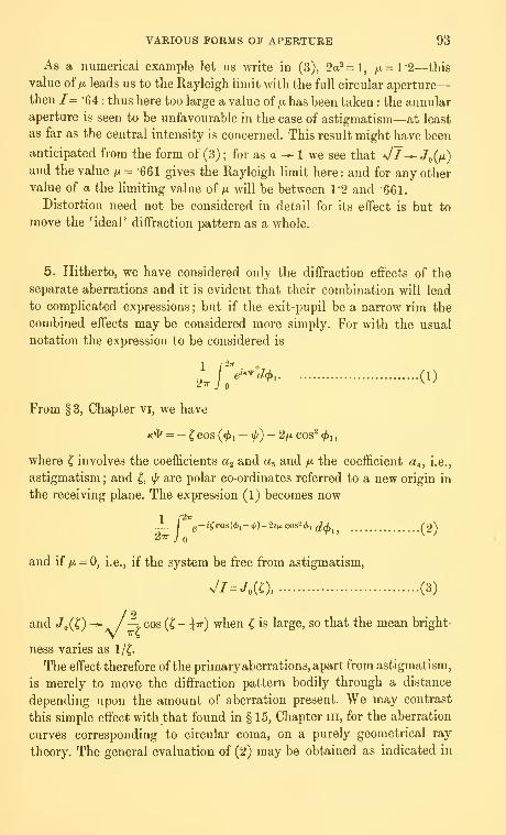
VARIOUS FORMS OF APERTURE 93
As a numerical example let us write in (3), 2a2=l, fjL= V2—this
value of /A leads us to the Rayleigh limit with the full circular aperture
—
then /= "64: thus here too large a value of yu. has been taken : the annular
aperture is seen to be unfavourable in the case of astigmatism—at least
as far as the central intensity is concerned. This result might have been
anticipated from the form of (3) ; for as a^ 1 we see that Jl-^ J^{ix)
and the value /x = •661 gives the Rayleigh limit here: and for any other
value of a the limiting value of /x will be between 1*2 and "Gei.
Distortion need not be considered in detail for its effect is but to
move the 'ideal' diffraction pattern as a whole.
5. Hitherto, we have considered only the diffraction effects of the
separate aberrations and it is evident that their combination will lead
to complicated expressions; but if the exit-pupil be a narrow rim the
combined effects may be considered more simply. For with the usual
notation the expression to be considered is
Lf?'*^^' (1)
From § 3, Chapter vi, we have
K* = - C COS (</>i— f)- 2/A cos^ <^i
,
where C involves the coefficients aj and a^ and /j. the coefficient a^, i.e.,
astigmatism ; and ^ if/ are polar co-ordinates referred to a new origin in
the receiving plane. The expression (1) becomes now
1 r^""
2ir J Q
and ii fji = 0, i.e., if the system be free from astigmatism,
s/l-JoiO, (3)
and «/o(0 "*"a. /~> ^°^ (^ ~ 4^^) ^^^^ ^ is large, so that the mean bright-
ness varies as l/(.
The effect therefore of the primary aberrations, apart from astigmatism,
is merely to move the diffraction pattern bodily through a distance
depending upon the amount of aberration present. We may contrast
this simple effect with that found in § 15, Chapter iii, for the aberration
curves corresponding to circular coma, on a purely geometrical ray
theory. The general evaluation of (2) may be obtained as indicated in

94 VARIOUS FORMS OF APERTURE
the preceding chapter; but we can obtain the information we desire
by writing i/' = 0, 7r/2 : then
27r j ^ m=0 ^ I L^; <>
if i/^ = 7r/2 ; while if t/' = we have
1/Sf " l2w J„C^^
.(5)
6. The Slit Aperture. Let the exit-pupil consist of two parallel
rectangular apertures symmetrically placed with respect to the axis of
%'
y and extending from y ^+a toy' = -a;\et the breadth be given by
z^b,b' and z = -b,-b', so that S=^a{b- b'). Thus in the absence of
aberrations (jP=0) and upon the paraxial image plane (X=0) the
integral which we have to consider is
\ fL-j«{pp'/cJ)cos(*i-<i.') dv'dz =—7-,— 77\ \\e-^^''i'^'^^^y'+^^'^ dy'dz'Aa(b-b')]] ^ Aa(b-b')jj ^
(1)
if k, k be the co-ordinates of the pole at which the light intensity is
required; and (1) takes the form
sin (Kak/d)fsin (Kbk/d) _ sin {Kb'k\d) \ 1 ,y.
{Kah\dY i Kkld Kkjd ] b-b ^^
The case of practical importance arises when k = 0, i.e., we consider the
intensity upon a line in the receiving plane parallel to the/ axis above:
and then
/y_ sin (Kak/d) _ sin z .„n
~ Kahjd z '
where z is the usual wave-length co-ordinate. It is evident that an
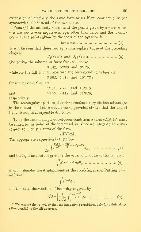
VARIOUS FORMS OF APERTURE 95
expression of precisely the same form arises if we consider only one
symmetrical slit instead of the two above.
From (3) the intensity vanishes at the points given hy z = mr, where
n is any positive or negative integer other than zero; and the maxima
occur at the points given by the roots of the equation in z,
tan z = z (4)
It will be seen that these two equations replace those of the preceding
chapter
Ji(s) = and J^{z) = Q (5)
Comparing the minima we have from the above
3-142, 6-283 and 9-425,
while for the full circular aperture the corresponding values are
3-832, 7-016 and 10-173:
for the maxima they are
4-494, 7-725 and 10943,
and 5-135, 8-417 and 11*620,
respectively.
The rectangular aperture, therefore, confers a very distinct advantage
in the resolution of close double stars, provided always that the loss of
light be not an insuperable difficulty.
7. In the case of simple out-of-focus conditions a term KXp^l2d^ must
be added to the index of the integrand, or, since we integrate here with
respect to y' only, a term of the form
The appropriate expression is therefore
iKXy'-_ ixpp'
^•^ "^ dy\ (1)
and the light intensity is given by the squared modulus of the expression
/,
1
gi(^vi-zv) ^^* (^2)
where fi denotes the displacement of the receiving plane. Putting z^Owe have
rl
and the axial distribution of intensity is given by
/:
JT-1 /•2«/« i]I^
I
-7= e'' ^, (3)vw J2^/1
* We assume that ip' = 0, so that the intensity is considered only for points along
a line parallel to the slit aperture.

96 VARIOUS FORMS OF APERTURE
where fi = 2Trn; and the value of this may be read off at once from tables
of Fresnel's integrals. In general if z = - 2-kN we have
V7= i-f'JnJ 1
— N'i'Jn+~ ijrP
a/w 2 7,e at •(4)
2jnJN
by means of the substitution vjfj. - z/2jf^ ^ tJir/'Z ; and this also is
readily obtainable from tables of Fresnel's integrals.
The extension of these results to take into account the presence of
spherical aberration leads clearly to the expression
/ 0i(-Zv+ tJ.v-+i>v*+...)(^f^
J.(5)
where v, ... denote aberrations of higher orders. In the particular case
of first order aberration only we have
J on=o
I
nJ
upon the axis of the system ; where
2/™ = W+^(«»"-^ -+••• +_„tv
2 2.4...2r
n=o|w 2W+1 ' .(6)
From (3) ii n= l we have
/ = 'y^^dv -•8319,
so that n^l brings us practically to the Rayleigh limit ; this then is
the maximum shift of focus plane permissible. Again for the point
z(=- 2ttN) upon the plane we have
/
l+2Ar
ei^vv^dv2N
and from tables the following values appear:
N= -1 -2 -3 -4 -5 -6 -7 '8
/=-8319 -6486 -4837 -3251 '1902 -0883 -0344 -0089 -0207
The first maximum is given, therefore, by iV= '73, approximately, and
its radius is 27r x 73, i.e., 4'6.
The general axial intensity in the presence of first order aberration
given by V = 27rwi is given by the squared modulus of
£Here Wi = ^ ^^^ n = -l gives very nearly the Rayleigh limit, so that
with change of focus one-and-three-quarter wave-lengths of first order

VARIOUS FORMS OF APERTURE 97
spherical aberration are permissible; it will be remembered that with the
full circular aperture one wave-length only of first order aberration is
permissible.
8. If coma alone be present we have from Chapter vi, § 3
Fip' pp'"^ - 2aB -Tj- cos ^1 - -J- cos «^i,
where we have written </>' =;
i.e., '^ = 2a,^:^J'(y- + z'^)-P^,
if we use the variables appropriate to the slit aperture. Neglecting the
z' dimension we are led to an expression of the form
^^^e^^^y'-^y^ dy, (1)/:
where A and B are constants ; and since the function in the index of
the exponential is odd this gives—apart from a numerical factor
—
\\o&{Af-By)dy, (2)J
so that in the usual notation the light intensity at a point z in the
presence of an amount of coma represented by y8 is given by
^1=1 cos (^u^-zu)du (3)
This result applies only to the Gaussian image plane but change of
focus may be included by the addition of a term fxu^ to the argument of
the circular function ; but as indicated in § 8, Chapter vi, the effect upon
the Gaussian plane is the most important. The positions of the turning
values of /, and these in general will be maxima, are given by the roots
of the equation in z
Isin {/3jv^-zJu)du = (4)
From (3) if ^ = 3 '25 the maximum value of the intensity occurs at
the point z=l'15 and it is 78 times the intensity at the theoretical
image in the absence of coma ; this degree of coma therefore brings us
to the limit for the slit aperture. ;8 = 4 brought us to the limit with the
full circular aperture so that to this extent the slit aperture is seen to
be unfavourable with coma.
But the radius of the first dark 'ring' in the direction away from the
head of the geometrical coma figure is 275 here, as compared with 3 "35

98 VARIOUS FORMS OF APERTURE
with the full circular aperture ; in the Airy disc this same radius is 3 "83.
For the first bright ring the figures are respectively 4"75; 5*35 ; 5'14.
I-Snt Aperture
1I= Circular >•
The diagram shews the intensity distribution along the line in the
image plane parallel to the aperture, in the case )8 = 4; and the dotted
curve shews the distribution along the same line when the aperture is
a circle and coma is present to the same degree.
9. With curvature and astigmatism we have
where we have written <^' = and <^i = 0; so that upon the central line
given by p'd +XY^ - 0, we have an expression of the form
I ei^p'dp,J -a
reducing in the usual way to
Ce^^'^'du, (1)

VARIOUS FORMS OF APERTURE 99
where A. as usual measures the distance from the primary focus. If the
slit aperture be rotated through a right angle the expression is
ne^^'^^'du, (2)
/:
where A.' measures the distance from the secondary focus. Away from
the central line we have, corresponding to (1), the integral
\ei>^n"-izug^ ("3)
This is of the form discussed in the preceding chapter ; and it may be
evaluated immediately from tables of Fresnel's Integrals.
It is evident that the function of the slit aperture is to eliminate
rays travelling to the focal line parallel to it; simple out-of-focus con-
ditions are therefore reproduced.
The effect of distortion is merely to move the diffraction pattern as
a whole and the results of § 7 may therefore be quoted.
10. The Semi-Circular Aperture. Let the exit-pupil be semi-circular
in form ; then two cases arise : we may assume the Gaussian image
point to lie upon the projection in the receiving plane of the diameter
of the semi-circle, in which case ^ ^i $ tt, in the usual notation; or we
may suppose the image point to lie upon a perpendicular line, i.e.,
- 7r/2 ^ c^i ^ 7r/2. Intermediate cases occur but the foregoing are the only
two which we shall consider. And taking the first possibility we are led,
for an aberrationless system, to the expression
{"'pap f%-'"'cos(<^,-*')6?,^j, (1)Jo Jo
where td =-- Kpp.
aa
Now cos {x cos 6) = J^(x)+ 2 2 (- 1)" J^ni^) COS 2n6,n-l
and sin (a: cos 0) = 2 2 (-1)" J^n+i (^) cos (2?^ + 1) ^
;
n=0
so that
Ie-t<cos(</.,-</.')(^^=
j cos (t cos ^1 - <f>') d(j>, - i / sin (^ cos t/)i -</>') (/^iJo Jo Jo
= 7rJ,(t)-^{r,(t), (2)
where r]{t) = Ji{t)sin<}> -^-z + —^
—
^.... (3;

100 VARIOUS FORMS OF APERTURE
If we write, as usual, zd=Kp^p' then the expression whose squared
modulus gives the light intensity is
^2 j^WJoii)-4.iv(t)]tdt (4)
It is seen that this reduces to unity at the Gaussian image, where z = 0;
we have, therefore,
"^-^m (^)
if i(,z)={'y,{t)tdt.
Thus /={?^y.5||iJl)|'(6)
11. If ^' = 0, i.e., if the pole lie upon the edge of the projection of
the aperture upon the receiving plane, then y]{t) = Q; so that (6) re-
duces to
and this is as in the Airy disc. If <^' = Tr/'i, then
so that K{z)= \\{t)tdt^z'i ^^ + h l'{l-J,it)}dt, (1)Jo n=i^n — i^ Jo
and 1-J„(;^) = 2 2 J,„(4
Thus (1) combined with (6) of the preceding paragraph gives the light
intensity at distance ;:; from the Gaussian image upon the line 4>' = x*-
It is worthy of notice that the maxima and minima of the intensity
are now at the points given by the roots of the equation in z
^^- j,(z)j,(z) _ d a(z)]im (2)16 az) dz
From the preceding it is evident that the effect of the aperture is to
scatter light into the outer parts of the field. There will be no dark points
now upon the line 4*' = 7r/2, nor, indeed, anywhere except upon the line
^' = (or tt).
* Formulae equivalent to these were given by Bruns, Astron. Nachr. vol. civ,
p. 1 (1883).

VARIOUS FORMS OF APERTURE 101
12. In the presence of coma, we have, upon the paraxial image plane,
* = --^cos(«^i-.A),
where G cos i/' = p' cos <^' - 2ag yi p^jd^, C sin iff = p sin <^'
from §3, Chapter vi; so that we have to consider the expression
pdp e '^ rf<^,
Jo Jo
2
Trpi^
l?//*H»(f)-Kf)}from (2) § 10.
By means of the substitution Kpp =zdjv, zd = xpip' this reduces to
/ Jo(u)dv / rj{u)dv, (1)Jo T Jo
where u^ = :^v- 2zl3if cos <^' + )8^v* and ^, as usual, is the measure of the
coma present; the light intensity is given by the squared modulus of (1).
Upon the axis of the coma figure </>' = 0, and then rj (u) = 0; so that
VA j JoizJv-P'J^)dv, (2)
and this is the same formula as with the full circular aperture. At right-
angles to the axis of the coma figure <^' = 7r/2, and (1) becomes
fjMdv-- i\{u)dv, (3)Jo 71" Jo
where tv^ — z'^v + fi-v^.
Here the effect of closing down the aperture is seen in the presence
of the second integral.
13. Let us now take the second possibility of § 10, i.e., let us assume
that - 7r/2 ^ <^i ^ 7r/2 ; then we are led to the formula
A (',,, r ,-"?-'*->,(1)
"^Pl Jo J -7r/2
/•t/2
Now / e-'*^s('^'-^hi<l)i^7rJo(t)-Uvi(t),J -7r/2
where
rj^{t) = Ji{t) COS ip + ^Jsit) cos 3l/' + ^Jsit) cos Si/' + ...
.
* The expression for ij ( ~Jcontains ^ instead of <p', as in § 10, (3).

URLfNGTONDATE DUE
102
The expression,
tensity is
7rr
4.
where u has the
and
ARR. ^ Ui ffr^
and we have
while if </>' = 7r/2 _
Jo
14. As we h{
governed by the
simple out-of-for
But with the inti.
As in §11 ofChj
•
;nfy
n-
re
i^e
ie
PRINTED IN U.S. •0,
where now ^ i/^
intensity is to b(
line; and the rai gaylord
i.e., upon the cei jr;
but in the general case, ^ ^ 0, we are led to an expression in Struve's
Fanctions and reference must be made to the above-mentioned paper*.
Again, the effect of distortion is merely to move bodily the whole
diffraction pattern produced by an aberrationless system and therefore
no further investigation is required.
REFERENCES
Rayleigh. Sci. Papers, iii, p. 90.
Steward. Phil. Trans. A, 225 (1925).
Proc. Opt. Co7ivention (1926).
* Phil. Trans. A, 225 (1925), Part in.

QC 355.S8
3 9358 00208376 1
355S8
Steward, George Coton
The symmetrical optxcal
system
BURL
QC355S8
Steward^ George Coton»The symmetrical optical system» by G.
C. Steward. Cambridge [ Eng. ] TheUniversity presst 1928«
viiif 102 p» diagrs« 22 cra«(Cambridge tracts in mathematics and,roathematical physics» no» 25)
208376
BURLINGTON
MBNU FEB 21, '75 1184332 NEBbp 28-23204

QC 355.S8
3 9358 00208376 1
PUBLISHED BYTHE SYNDICS OF THE CAMBRIDGE UNIVERSITY PRESS
Bentley House, 200 Euston Road, London, N.W. 1
American Branch: 32 East 57th Street, New York 22, N.Y.
PRINTED IN GREAT BRITAIN