The Survey of a Triangulation System
30
The University of Maine The University of Maine DigitalCommons@UMaine DigitalCommons@UMaine Maine History Documents Special Collections 6-1905 The Survey of a Triangulation System The Survey of a Triangulation System Charles Lester Bailey Francis Trenholm Crowe Follow this and additional works at: https://digitalcommons.library.umaine.edu/mainehistory Part of the History Commons This Thesis is brought to you for free and open access by DigitalCommons@UMaine. It has been accepted for inclusion in Maine History Documents by an authorized administrator of DigitalCommons@UMaine. For more information, please contact [email protected].
Transcript of The Survey of a Triangulation System

The University of Maine The University of Maine
DigitalCommons@UMaine DigitalCommons@UMaine
Maine History Documents Special Collections
6-1905
The Survey of a Triangulation System The Survey of a Triangulation System
Charles Lester Bailey
Francis Trenholm Crowe
Follow this and additional works at: https://digitalcommons.library.umaine.edu/mainehistory
Part of the History Commons
This Thesis is brought to you for free and open access by DigitalCommons@UMaine. It has been accepted for inclusion in Maine History Documents by an authorized administrator of DigitalCommons@UMaine. For more information, please contact [email protected].

THE
SURVEY
0 F
A TRIANGULATION SYSTEM
A THESIS
PRESENTED TO THE FACULTY
OF THE
UNIVERSITY OF MAINE
FOR THE ATTAINMENT OF THE DEGREE OF
BACHELOR OF SCIENCE IN CIVIL ENGINEERING
BY
CHARLES LESTER BAILEY
AND
FRANCIS TRENHOLM CROWE
ORONO MAINE
JUNE 1905

TRIANGULATION
Triangulation is a trigonometrical survey and consists
of the operation and immediate results of measuring the angles
of a network of triangles laid out on the ground by marking
the vertices. It usually proceeds from a base line,
the measurement of which is necessary, although not a part of
the triangulation proper. The geographical position
of the extremities of the base having been decided upon and
set, and the triangulation or operation of measuring the angles
having been completed; by trigonometrical calculation called
the reduction of the triangulation, involving the process of
distributing the errors, called the adjustment of the triang
ulation, the geographical position of all the other vertices
are calculated, assuming the figure of the earth to be known.
The system to be considered in this thesis is one
established for the use of a topographical survey by the
Civil Engineering Summer School and to form a portion of the
Lower Penobscot River System, to be completed in some future
time by the same department.
In presenting this system we do not claim that it is
mathematically the most nearly perfect system that the topogra
phy of the country will afford, for owing to our limited
financial approtition we were unable to build observation
towers and in numerous favorable locations we were unable to

TRIANGULATION
Triangulation is a trigonometrical survey and consists
of the operation and immediate results of measuring the angles
of a network of triangles laid out. on the ground by marking
the vertices. It usually proceeds from a base line,
the measurement of which is necessary, although not a part of
the triangulation proper. The geographical position
of the extremities of the base having been decided upon and
set, and the triangulation or operation of measuring the angles
having been completed; by trigonometrical calculation called
the reduction of the triangulation, involving the process of
distributing the errors, called the adjustment, of the triang
ulation, the geographical position of all the other vertices
are calculated, assuming the figure of the earth to be known.
The system to be considered in this thesis is one
established for the use of a topographical survey by the
Civil Engineering Summer School and to form a portion of the
Lower Penobscot River System, to be completed in some future
time by the same department.
In presenting this system we do not claim that it is
mathematically the most nearly perfect system that the topogra
phy of the country will afford, for owing: to our limited
financial approtition we were unable to build observation
towers and in numerous favorable locations we were unable to

2.
secure the priviledge of placing stations, but taking this
into consideration, we believe it to be the best system avail
able for the territory covered. The system covers the
territory of the towns of Webster, Orono, and Stillwater and
the valley of the Stillwater River between them. It is
controlled by twelve permanent stations with numerous church
steeples and towers tied in for palne table use.
The base line of the system is long and extends from
a point directly under a signal placed on the top of the stand
pipe of the University water supply system to a point in Mr.
Gilbert’s field about two hundred feet to the north east of
the north west corner of Mr. Charles Crowell’s barn on the
corner of Park and College Streets. This base was
measured by A. W. Collins and L. H. Mitchell in the spring of
1905 and presented to the University as a thesis.
THE STATIONS
The stations are constructed as follows
A one and thre quarter inch galvanized iron pipe five feet
long having been split and flanged at the lower end is placed
in the ground to such a depth that the upper end is about six
inches below the surface of the ground. Earth and stone
is then tamped in throuoghly about it so that there is no
possible chance for the pipe to move either vertically or
horizontally. The pipe having been placed, it is filled

Plate N0 1.

Plate No. 2

3
with a core of neat cement and. a nail placed, in the center of
the top for a transit point. Where ever the stations
came on ledge where pipes were not practicable, a one inch
hole five inches deep was drilled, and a half inch iron rod
six inches long placed in it and surrounded with neat cement.
The tope of the stations are surrounded by boxes of wood 12
by 12 by 9 inches with a cover which is placed over it when '
the station is not in use.
THE SIGNALS
The signals are constructed as follows
A peice of 2 by 4 twenty feet long is used for poles, on one
of the ends of which a piece of white signal cloth two feet
by three is tacked and the other end notched and cleated so
as to form a socket which will just fit over the end of the
station pipe. From a point just under the signal cloth
a hole is bored in the post from which radiate three guy wires
which terminate at stakes so placed as to make the signal
perpendicular when the guys are attached. For the
drawing see Plate No. 1 and Plate No. 2.
MEASUREMENT OP ANGLES
The method of repetition of angle was used which con
sists of measuring each angle independently by repeating it a

4
number of times by successive addition on the limb and then
reading this multiplied angle which is divided by the number
of repetitions to give the true value of the angle.
PROGRAMME
Telescope Normal.
1. Set on left -station arid read both verniers.
2. Unclamp above and set on right station.
3. Unclamp below and set on left station.
4. Unclamp above and set on right station.
5. Unclamp below and set on left station.
6. Unclamp above and set on right station. Read verniers
Telescope Reversed.
1. Set on right station and read both verniers.
2. Unclamp above and set on fight station.
3. Unclamp below and set on left station.
z— • Unclamp above and set on right station.
5. Unclamp below and set on left station.
6. Unclamp above and set on right Station. Read verniers
Instruments used for sucessful triangulation must
be especially accurate for the measurement of horizontal angles.
The instrument used on this work was a Eugene Dietzen, No. 9
of the University equipment.

RECONNOISSANOE SOUTH
Before locating our stations in the near vicinity of
the village.of Orono, considerable time was spent in looking
over the near by country, so ais to locate points that would
make it possible at some future date to carry the system south
beyond the town.
First we looked over carefully the ground surrounding
Powell’s Hill with the view of proceeding south along that line,
the spot mn the crest of the hill just south of the main road
was the only clear spot along the whole ridge and there was a
narrow strip of woods just south of this clear space that runs
east for several hundred yards * We could have located a
station a little to the south west of Mr. Powell’s barn and
another just west of Mr. Gilbert’s residence that would be
visible from the hill but when we got thus far it was impossible
to locate another station on the high ground that could be seen
from the hill, and we could not go east toward the village
on account of the houses that intervened between the stations.
If we had had time and money to build to twenty foot
sihnal towers this would have been the best way to have gotten
around Orono. We finally decided that by locating our
stations at Vinal’s and Engel’s that it is easily possible to
locate two stations on the Webster side of the river and a
little to the south east of thesetthat will be readily visible
from them and fpom there one could locate stations just north

of Basin Mills and then again across the river and so proeeed
both along the river valley and upon the higher ground to the
west of the river.
.5*
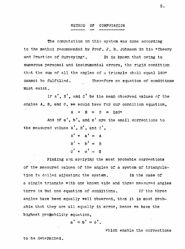
METHOD OF COMPUTATION
The computation on this system was done according
to the method recommended by Prof. J. B. Johnson in his “Theory
and Practice of Surveying". It is known that owing to£
numerous personal and instrumental errors, the rigid condition
that the sum of all the angles of a triangle shall equal 180°
cannot be fulfilled. Therefore an equation of conditions
must exist.
If A*, B1, and C* be the mean observed values of the
angles A, B, and C, we would have for our condition equation,
A + B + c = 180°
And if a*, b‘, and c’ are the small corrections to
the measured values A*, B*, and c’,
A' + a' = A
B1 + b' = B» t
c + c = 0
Finding and applying the most probable corrections
of the measured values of the angles of a system of triangula
tion is called adjusting the system. In the case of
a single triangle with one known side and three measured angles
thrre is but one equation of conditions. If the three
angles have been equally well observed, then it is most prob
able that they are all equally in error, hence we have the
highest probability equation,i . * ta = b = c .
which enable the corrections
to be determined
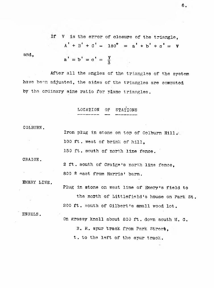
6
of closure of the
180° a ’ + b1
triangle,
+ c ‘ = V
and,V3
» * • a = b = c
After all the angles of the triangles of the system
have been adjusted, the sides of the triangles are computed
by the ordinary sine ratio for plane triangles.
LOCATION OF STATIONS
COLBURN.Iron plug in stone on top of Colburn Hill
100 ft . west of brink of hill,
150 ft. south of north line fence.
CRAIGE.2 ft. south of Craige’s north line fence,
800 ± east from Harris1 barn.
EMERY LINE.Plug in stone on west line of Emery*s field to
the notth of Littlefield’s house on Park st.
200 ft. south of Gilbert*s small wood lot.
ENGELS.On grassy knoll about 800 ft. down south M. C.
R. R. spur track from Park Street,
t. to the left of the spur track.

7
GRAVES.
McKNIGHT.
MEYER.
NORTH BASE.
POWELL.
SOUTH BASE.
STILLWATER.
VINAL.
In hay field north of Mrs. Graves' house .
30 ft. to S. W. of N. W. corner of adjoining
pasture.
On top of knoll 2 ft. south of first line fence
to the north of McKnight’s barn.
On top of knoll in pasture 125 ft. to north of
N. E. corner of Meyer’s north garden.
Under University stand pipe 2ft. west of
discharge pipe.
On top of Powell’s hill 100 ft. from brink and
200 fta. north of Powell south line fence.
In Gilbert’s field on Park street,
200 ft. to N.E. of N.E. corner Crowell’s barn.
Edge of Stillwater River bank,
200 ft. E. of E. end of Stillwater dam.
In stumpy, marshy lot west of Mr. Vinal’s house
in Webster,
140 feet S 4° 31* W of two white birch trees
at S.W. comer of Mr. Vinal’s wood lot.

8*
MEASURED AND ADJUSTED ANGLES
Tran .Sta. Obs .Sta. Meas.Angle. Mean Angle Adj.Angle
So. Base. No. Base. Tel. Nor.
to 1st R’d’g.
Colburn. 78° 57’ 30”L
4th R’d’g.
315° 49’ 30” 78° 57’ 22” 78° 56’ 57”
Tel. Rev.
1st R’d’g.
78° 57’ 0”
4th R’d’g,
315° 49’ 30”
So. Base. Powell Tel. Nor.
to 1st R’d’g.
Colburn 25° 22» 0»R
14th R’d’g.
355° 6’ 0” 25° 21’ 52”
Te 1. Rev.
1st R’d’g.
25° 22’ 0”
6th R’d’g.
152° 11’ 0”
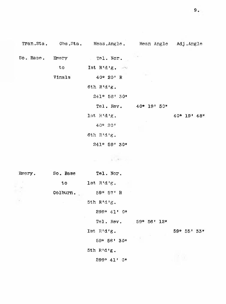
9
Tran. St a . Obs .sta. Meas.Angle. Mean Angle Adj .Angle
So. Base. Emery Tel. Nor.
to 1st R’d’g.
Vinals 40° 20» R
6th R’d’g.
241° 58’ 30”
Tel. Rev. 40® 19’ 50”
1st R’d’g. 40° 19» 48"
40° 20’
6th R’d’g.
241° 59’ 30”
Emery. So. Base Tel. Nor.
to 1st R’d’g.
Colburn. 59° 57’ R
5th R’d’g.
299° 41* 0"
Tel. Rev. 59° 56’ 12”
1st R’d’g. 59° 55’ 33”
59° 56’ 30”
5th R’d’g.
299° 41’ 0”

10
309° 50' 30"
Tran.Sta. Obs.Sta. Meas.Angle. Mean Angle Adj .Angle
Emery So. Base Tel. Nor.
to 1st R'd'g.
Engel 72° 10» 30"L
4th R'd’g.
288° 42’ 0"
Emery Vinals Tel. Nor.
to 1st R'd'g.
Engels 31° 7' R
6th R’d'g.
186° 43' 0"
Tel. Rev. 31° 7' 10"
1st R'd'g. 31° 7' 34"
31° 7' 0"
6th R’d'g.~)
186° 43' 0"
Emery Vinals Tel. Nor.
to 1st R'd'g.
So. Base . 103° 17' 0«R
3rd R'd'g.
309° 51' 0"
Tel. Rev. 103° 16» 45"
- 1st R'd'g. 103° 16' 43"
103° 17' 0"
3ed R'd'g.

11
Gath. Ch
Tran .sta. Obs .Sta. Meas.Angle Mean Angle Adj .Angle
Engels Emery Tel. Nor.
to 1st R’d’g.
Vinals 75® 24' 30»R
4th R’d’g.
293® 38’ 30”
Tel. Rev. 73® 24’ 45"
1st R’d’g. 73® 25’ 1"
73® 24* 30”
4t.h R’d’g.
293° 40’ 0”
Vinals So. Base Tel. Nor.
to 1st R’d’g.
Emery 36® 23* 30’’R
4th R’d’g.
145® 36’ 30”
Tel. Rev. 36® 24* 8"
1st R’d’g. 36® 23' 51”
36® 24’ 0”
4th R’d’g.
1«5® 36* 30”
Vinals So. Base. Tel. Nor.
to 1st R’d’g.
Mill St . 20® 29’ 30” L

12
Tran. sta. Obs .Sta. Meas.Angle Mean Angle Adj .Angle
Vinals Emery Tel. Nor.
to 1st R’d’g.
Engels 75° 27’ L
4th R'd’g. •
301® 48' O’’
Tel. Rev. 75° 27’ 0“
1st R’d’g. 75® 27' 24"
75° 27’
4th R'd'g.
301° 48* 0”
Powell No. Base. Tel. Nor.
to 1st R’d’g.
So. Base. 31® 50» 0“ R
4th R’d'g.
127® 20» 0"
Tel. Rev. 31° 50’ 0”
1st R’d'g. 31® 50» 0"
31° 50» 0”
4th R'd'g.
127° 20' 0”
Powell So.Base. Tel. Nor.
to 1st R'd’g.
Univ. Ch. 36® 5’ 0" R

13
Colburn
Tran .Sta.
Colburn
Obs .Sta. Meas .Angle Mean Angle Adj .Angle
Emery Tel. Nor.
to 1st R’d’g.
So. Base. 17° 131 0\R
4th R’d’g.
68° 54’ 0”
Tel. Rev. 17° 13* 15”
1st R’d’g. 17° 12’ 21”
17° 13’ 0”
4th R’d’g.
68° 54’ 0»»
No. Base. Tel. Nor.
to 1st R’d’g.
So. Base. 39° 9’ 0” R
4th R’d’g.
156° 36' 0”
Tel. Rev. 39® 9’ 0”
1st . R’d’g. 39® 8* 36”
39° 9’ 0”
4th R’d’g.
156° 36* 0”

14
61° 54 » 28”
Tran .Sta. Obs.Sta. Meas.Angle Mean Angle Adj .Angle
Colburn McKnight Tel. Nor.
to 1st R’d’g.
No. Base 18° 16’ 0” R
4th R’d’g.
73° 4’ 0”
Tel. Rev. 18® 16’ 0“
1st R’d’g. 18® 16’ 8”
18° 16» 0”
4th R’d’g.
73© 41 0”
Colburn So. Base Tel. Nor.
to 1st R’d’g.
Cath. Ch. 17° 36’ R
Colburn So. Base Tel. Nor.
to 1st R’d’g.
Univ. Ch. 30® 19’ R
No. Base. So. Base Tel. Nor.
to 1st R’d’g.
Colburn 61° 55’ 0” R
'4th R’d’g.
247° 39’ 0”
61® 54’ 52”

15.
Tran .Sta. Obs .Sta. Meas.Angle Mean Angle Adj.Angle
No. Base So .Base Tel. Rev.
to 1st R'd’g.
Colburn 61° 55’ 0”
4th R’d’g.
247° 40’ 0”.
No. Base So. Base Tel. Nor.
to 1st R’d’g.
McKnights 82® 40' 0” R
4th R'd'g.
330° 39’ 0”
Tel. Rev.
1st R'd'g.
82° 40' 0”
4th R’d'g.
330® 39' 0”
82® 39’ 45”
No. Base McKnights Tel. Nor.
to 1st R'd’g.
Graves 62® 59’ 0” R
4th R’d’g.
251° 55’ 0”
Tel. Rev. 62® 58’ 45”
1st R’d’g. 62° 58' 35”
62° 59» 0”
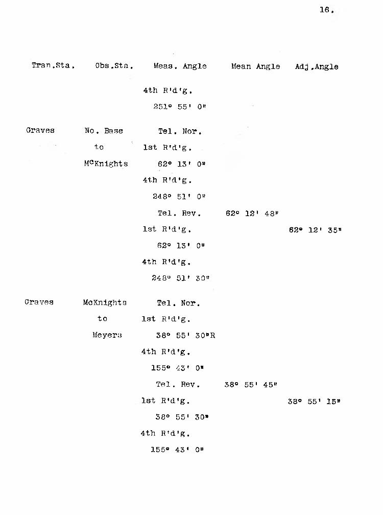
16
Tran.Sta. Obs .Sta. Meas. Angle Mean Angle Adj.Angle
Graves No. Base
to
McKnights
Graves McKnights
to
4th R’d’g.
251° 55’ 0”
Tel. Nor.
1st R’d’g.
62® 13’ 0”
4th R’d’g.
248° 51’ 0”
Tel. Rev.
1st R’d’g,
62° 13’ 0”
4th R’d’g.
248° 51’ 30”
62° 12' 48”
62® 12' 35”
Tel. Nor.
1st R’d’g.
1
Meyers 38° 55' 30”R
4th R’d’g.
155® 43* 0"
Te 1. Rev .
1st R’d’g.
38° 55' 30”
4th R’d’g.
38® 55' 45”
38® 55' 15”
155® 43’ 0”

17
593® 56* 0”
Tran .sta. Obs ,sta. Meas. Angle Mean Angle Adj.Angle
Graves Meyers Tel. Nor.
to 1st R’d’g.
Graige 98° 11» 30”R
4th R’d’g.
392° 44* 0”
Tel. Rev. 98® 11’ 0”
1st R’d’g. 98® 10» 45”
98° 11* 30”
4th R’d’g.
392° 44' 0"
McKnights No. Base Tel. Nor.
to 1st R’d’g,
Colburn 140® 59’ 30”
4th R’d’g.
593® 56’ 0”
Tel. Rev. 140® 59» 0”
1st R’d’g. 140® 59* 7®
140® 59’ 30”
4th R’d’g.

18
Tran. Sta. Obs. Sta. Meas. Angle Mean Angle Adj .Angle
McKnights Graves Tel. Nor.
to 1st R'd'g.
No. Base 54° 49' 0”R
4th R’d'g.
219® 16' 0”
Tel. Rev.
1st R’d'g.
54° 49' 0"
4th R'd'g.
219° 16' 0”
54® 49' 0”
54° 48' 50"
Mcknights Meyers
to
Graves
Tel. Nor.
1st R’d’g.
49° 0’ 0” R
4th R’d’g.
196° 0» 0”
Tel. Rev. 49* 0’ 0”
1st R’d'g. 48® 59’ 30"
49° 0’ 0”
4th R’d'g.
196° O' 0”

19.
Tran. Sta Obs. Sta Meas. Angle Mean Angle Adj .Angle
Meyers
189° 36• OM
Stillwater Tel. Nor.
to 1st R’d’g.
Craigs 47® 24* 0” R
4th R’d’g.
189° 36* 0”
Tel. Rev,
1st R’d’g.
47° 24* 0”
4th R’d’g.
47® 24* 0*’
47° 23’ 53”
Meyers Craigs Tel. Nor.
to 1st R’d’g.
Graves 36® 14» 0” R
4th R’d’g.
144° 55’ 0”
Tel. Rev.
1st R’d’g.
36° 14* 0”
4th R’d’g.
36° 13’ 45”
36® 13* 30”
144® 55* 0”

20
Tran. Sta. Obs. Sta. Meas. Angle Mean Angle Adj.Angle
Meyers Graves Tel. Nor.
to 1st R’d’g.
No. Base 44® 0’ 0” R
4th R’d’g.
175° 59’ 0”
Tel. Rev.
1st R’d’g.
44° 0’ 0”
4th R’d’g.
175° 59’ 0”
43° 59» 45”
Meyers No. Base Tel. Nor.
to 1st R’d’g.
Mcknights 48° 6’ O’’
4th R’d’g.
192° 24’ 0"
Tel. Rev. 48° 6’ 0”
1st R’d’g.
48° 6’ 0”
4th R’d’g.
192° 24’ 0”

21 ♦
Tran. Sta. Obs. Sta. Meas. Angle Mean Angle Adj.Angle
Meyers McKnights Tel. Nor.
to 1st R’d’g.
Colburn 42° 31' 0» R
4th R’d’g.
170° 2’ 0”
Tel, Nor.
1st R’d’g’
42° 31’ 0”
4th R’d’g.
170° 2' 0”
42° 30’ 30”
Meyers
Church
Stillwater Tel . Nor.
to 1st R’ d’g.
Stillwater 25° 47' 0” L

28
Tran.
Craige
Sta. Obs. Sta. Meas. Angle Mean Angle Adj.Angle
Graves
to
Meyers
Tel. Nor.
1st R’d'g.
45° 35’ 30"R
4th R'd'g.
182° 22* 30”
Tel. Rev. 45° 35’ 37"
1st R'd’g.
45° 35' 30”
4th R’d’g.
182® 22’ 30"
45° 35' 15"
Graige Meyers Tel. Nor.
to
Stillwater 71° 52’ 30"R
4th R’d’g
287° 29»- 0»
Tel. Rev. 71° 52’ 221’’6
1st R’d’g. 71° 52’ 15"
71° 52’ 30"R
4th R’d’g
287° 29' 0”

23
Tran. Sta. Obs. Sta. Meas.Angle Mean Angle Adj.Angle
Stillwater Criage Tel. Nor.
to 1st R’d’g.
Meyers 60® 44’ 0”R
6th R’d’g.
364° 24’ 0”
Tel. Rev.
1st R’d’g.
60° 44' 0”
60® 44* 0”
60® 43' 52»
6th R’d’g.
364® 24’ 0“
Church
Stillwater Meyers Tel. Nor.
to 1st R’d’g.
Stillwater 58® 1’ 0”