THE STORY ABOUT THE REDUCTION IN NUMBER OF WINDMILL …
14
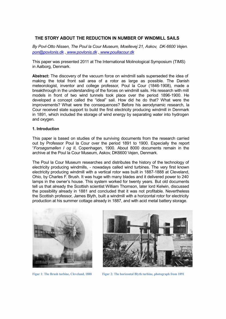
THE STORY ABOUT THE REDUCTION IN NUMBER OF WINDMILL SAILS By Povl-Otto Nissen, The Poul la Cour Museum, Moellevej 21, Askov, DK-6600 Vejen. [email protected] , www.povlonis.dk , www.poullacour.dk This paper was presented 2011 at The International Molinological Symposium (TIMS) in Aalborg, Denmark. Abstract: The discovery of the vacuum force on windmill sails superseded the idea of making the total front sail area of a rotor as large as possible. The Danish meteorologist, inventor and college professor, Poul la Cour (1846-1908), made a breakthrough in the understanding of the forces on windmill sails. His research with mill models in front of two wind tunnels took place over the period 1896-1900. He developed a concept called the “ideal” sail. How did he do that? What were the improvements? What were the consequences? Before his aerodynamic research, la Cour received state support to build the first electricity producing windmill in Denmark in 1891, which included the storage of wind energy by separating water into hydrogen and oxygen. 1. Introduction This paper is based on studies of the surviving documents from the research carried out by Professor Poul la Cour over the period 1891 to 1900. Especially the report “Forsøgsmøllen I og II, Copenhagen, 1900. About 8000 documents remain in the archive at the Poul la Cour Museum, Askov, DK6600 Vejen, Denmark. The Poul la Cour Museum researches and distributes the history of the technology of electricity producing windmills, - nowadays called wind turbines. The very first known electricity producing windmill with a vertical rotor was built in 1887-1888 at Cleveland, Ohio, by Charles F. Brush. It was huge with many blades and it delivered power to 240 lamps in the owner’s house. This system worked for twenty years. But old documents tell us that already the Scottish scientist William Thomson, later lord Kelwin, discussed the possibility already in 1881 and concluded that it was not profitable. Nevertheless the Scottish professor, James Blyth, built a windmill with a horizontal rotor for electricity production at his summer cottage already in 1887, and with acid metal battery storage. Figur 1: The Brush turbine, Cleveland, 1888 Figur 2: The horizontal Blyth turbine, photograph from 1891
Transcript of THE STORY ABOUT THE REDUCTION IN NUMBER OF WINDMILL …
THE STORY ABOUT THE REDUCTION IN NUMBER OF WINDMILL SAILS
By Povl-Otto Nissen, The Poul la Cour Museum, Moellevej 21, Askov, DK-6600 Vejen.
[email protected] , www.povlonis.dk , www.poullacour.dk This paper was presented 2011 at The International Molinological Symposium (TIMS) in Aalborg, Denmark. Abstract: The discovery of the vacuum force on windmill sails superseded the idea of making the total front sail area of a rotor as large as possible. The Danish meteorologist, inventor and college professor, Poul la Cour (1846-1908), made a breakthrough in the understanding of the forces on windmill sails. His research with mill models in front of two wind tunnels took place over the period 1896-1900. He developed a concept called the “ideal” sail. How did he do that? What were the improvements? What were the consequences? Before his aerodynamic research, la Cour received state support to build the first electricity producing windmill in Denmark in 1891, which included the storage of wind energy by separating water into hydrogen and oxygen. 1. Introduction This paper is based on studies of the surviving documents from the research carried out by Professor Poul la Cour over the period 1891 to 1900. Especially the report “Forsøgsmøllen I og II, Copenhagen, 1900. About 8000 documents remain in the archive at the Poul la Cour Museum, Askov, DK6600 Vejen, Denmark. The Poul la Cour Museum researches and distributes the history of the technology of electricity producing windmills, - nowadays called wind turbines. The very first known electricity producing windmill with a vertical rotor was built in 1887-1888 at Cleveland, Ohio, by Charles F. Brush. It was huge with many blades and it delivered power to 240 lamps in the owner’s house. This system worked for twenty years. But old documents tell us that already the Scottish scientist William Thomson, later lord Kelwin, discussed the possibility already in 1881 and concluded that it was not profitable. Nevertheless the Scottish professor, James Blyth, built a windmill with a horizontal rotor for electricity production at his summer cottage already in 1887, and with acid metal battery storage.
Figur 1: The Brush turbine, Cleveland, 1888 Figur 2: The horizontal Blyth turbine, photograph from 1891
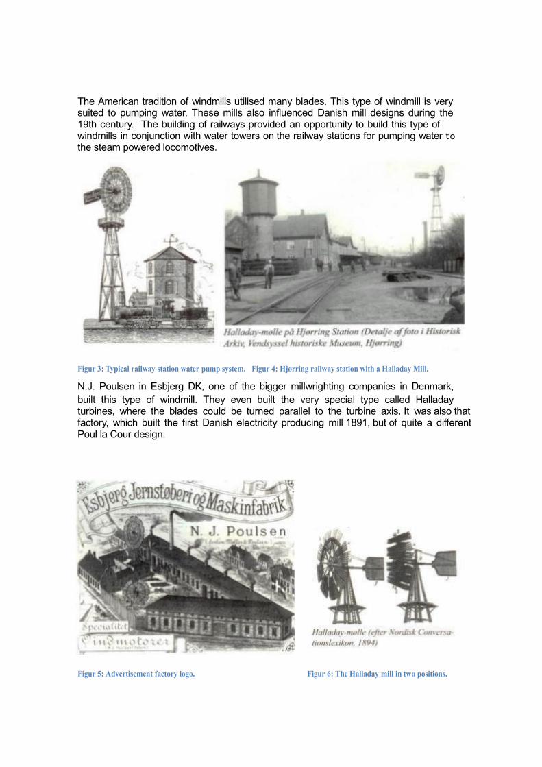
The American tradition of windmills utilised many blades. This type of windmill is very suited to pumping water. These mills also influenced Danish mill designs during the 19th century. The building of railways provided an opportunity to build this type of windmills in conjunction with water towers on the railway stations for pumping water to the steam powered locomotives.
Figur 3: Typical railway station water pump system. Figur 4: Hjørring railway station with a Halladay Mill.
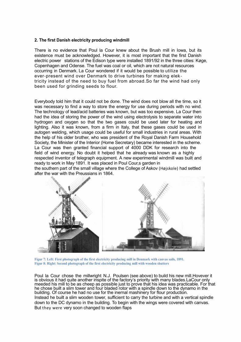
N.J. Poulsen in Esbjerg DK, one of the bigger millwrighting companies in Denmark,
built this type of windmill. They even built the very special type called Halladay turbines, where the blades could be turned parallel to the turbine axis. It was also that factory, which built the first Danish electricity producing mill 1891, but of quite a different Poul la Cour design.
Figur 5: Advertisement factory logo. Figur 6: The Halladay mill in two positions.
2. The first Danish electricity producing windmill There is no evidence that Poul la Cour knew about the Brush mill in Iowa, but its existence must be acknowledged. However, it is most important that the first Danish electric power stations of the Edison type were installed 1891/92 in the three cities: Køge, Copenhagen and Odense. The fuel was coal or oil, which are not natural resources occurring in Denmark. La Cour wondered if it would be possible to utilize the ever-present wind over Denmark to drive turbines for making elek - tricity instead of the need to buy fuel from abroad.So far the wind had only been used for grinding seeds to flour. Everybody told him that it could not be done. The wind does not blow all the time, so it was necessary to find a way to store the energy for use during periods with no wind. The technology of lead/acid batteries was known, but was too expensive. La Cour then had the idea of storing the power of the wind using electrolysis to separate water into hydrogen and oxygen so that the two gases could be used later for heating and lighting. Also it was known, from a firm in Italy, that these gases could be used in autogen welding, which usage could be useful for small industries in rural areas. With the help of his older brother, who was president of the Royal Danish Farm Household Society, the Minister of the Interior (Home Secretary) became interested in the scheme. La Cour was then granted financial support of 4000 DDK for research into the field of wind energy. No doubt it helped that he already was known as a highly respected inventor of telegraph equipment. A new experimental windmill was built and ready to work in May 1891. It was placed in Poul Cour,s garden in the southern part of the small village where the College of Askov (Højskole) had settled after the war with the Preussians in 1864. Figur 7: Left: First photograph of the first electricity producing mill in Denmark with canvas sails, 1891. Figur 8: Right: Second photograph of the first electricity producing mill with wooden shutters
Poul la Cour chose the millwright N.J. Poulsen (see above) to build his new mill.Hovever it is obvious it had quite another inspite of the factory’s priority with many blades.LaCour only meeded his mill to be as cheep as possible just to prove that his idea was practicable. For that he chose built a slim tower and four bladed rotor with a spindle down to the dynamo in the building. Of course he had no use for the inernal mashinery for flour production. Instead he built a slim wooden tower, sufficient to carry the turbine and with a vertical spindle down to the DC dynamo in the building. To begin with the wings were covered with canvas. But they were very soon changed to wooden flaps

For some reason the name of Poul la Cour is connected to this special design of a mill but that appearance was not the big invention. The first important invention was the Kratostate1892: A device with weights, wheels and
belts, which could smooth the variating rotation frekvency from the turbine to a constant
rotation output to drive the wind tunnel fan and thereby give a constant air flow..
The next problem was the storing of the wind energy. After many detailed eksperiments
electrolyzer vessels were installed for seperating water into Hydrogen and Oxygen The
wessels were placed in the larger building next to the mill building together with
two big gas containers in the ground. From here the two gases were transported through lead pipes 300 metres to the college buildings where they were used as lighting gas in very special lamps. The installation functioned over seven years from 1895 to 1902. But this is quite another story, which is not the subject of this paper. Anyway it is important to remember that the light succes released more financial support which made it possible to continue the research as The State Experimental Wind Laboratory with Poul la Cour as director. 3. An aerodynamic surprise
Millwrights were excited because a new market had appeared: The production of electricity and light using windmills. One millwright, Chr. Sørensen from Skanderborg, made contact to Poul la Cour in 1896. Sørensen had invented a new design of a windmill rotor, “Keglevindfanget” (The Conical Wind Catcher), and he asked la Cour for help to get documented test results in order to seek a patent. Chr. Sørensen himself had started research on models with different rotor types – all with same diameter - in front of a barrel with a blowing ventilator in one of the open ends. It was called a “blæsecylinder” (blowing cylinder) and it was possibly the first experimental wind tunnel. Until then windmill rotors most often were tested on a rotating merry-go- round (carousel) arm. Using this method it was difficult to create a constant air flow long enough to make reliable measurements, but la Cour now had suitable equipment,. the Kratostate, which could smooth out the variating rotations from the turbine to a constant rotation and thereby a steady wind flow, with a deviation of only 1 per thousend. No other machinery could do that.
Figur 9: Left: This photograph from 1896 shows the "conic wind cather" with twelwe sails. Figur 10: Right: The conical wind catcher rotor as a roof mill wtih only six sails.
The first model Sørensen designed had twelve sails. La Cour found almost immediately
that the performance improved when some of the sails were removed. That was a surprise because the most common opinion at that time – even among millwrights - was that a mill should have as many blades as possible. This was supported by the hitherto accepted scientific formula:
L = 0.0338 F v3
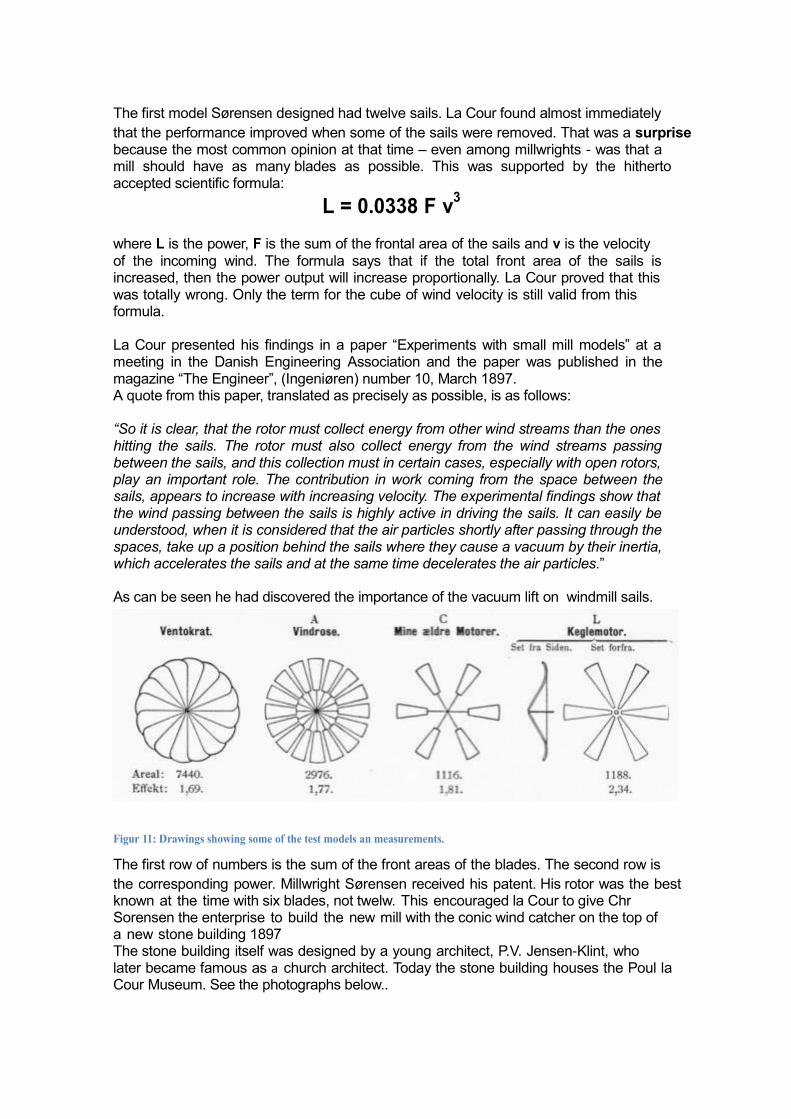
where L is the power, F is the sum of the frontal area of the sails and v is the velocity of the incoming wind. The formula says that if the total front area of the sails is increased, then the power output will increase proportionally. La Cour proved that this was totally wrong. Only the term for the cube of wind velocity is still valid from this formula. La Cour presented his findings in a paper “Experiments with small mill models” at a meeting in the Danish Engineering Association and the paper was published in the magazine “The Engineer”, (Ingeniøren) number 10, March 1897. A quote from this paper, translated as precisely as possible, is as follows: “So it is clear, that the rotor must collect energy from other wind streams than the ones hitting the sails. The rotor must also collect energy from the wind streams passing between the sails, and this collection must in certain cases, especially with open rotors, play an important role. The contribution in work coming from the space between the sails, appears to increase with increasing velocity. The experimental findings show that the wind passing between the sails is highly active in driving the sails. It can easily be understood, when it is considered that the air particles shortly after passing through the spaces, take up a position behind the sails where they cause a vacuum by their inertia, which accelerates the sails and at the same time decelerates the air particles.” As can be seen he had discovered the importance of the vacuum lift on windmill sails.
Figur 11: Drawings showing some of the test models an measurements.
The first row of numbers is the sum of the front areas of the blades. The second row is
the corresponding power. Millwright Sørensen received his patent. His rotor was the best known at the time with six blades, not twelw. This encouraged la Cour to give Chr Sorensen the enterprise to build the new mill with the conic wind catcher on the top of a new stone building 1897 The stone building itself was designed by a young architect, P.V. Jensen-Klint, who later became famous as a church architect. Today the stone building houses the Poul la Cour Museum. See the photographs below..
Figur 12: Left: Photograph of the wind laboartory mills, 1897. Figur 13: Right: Photograph of the wind laboratory mills, 1900.
4. Further aerodynamic research
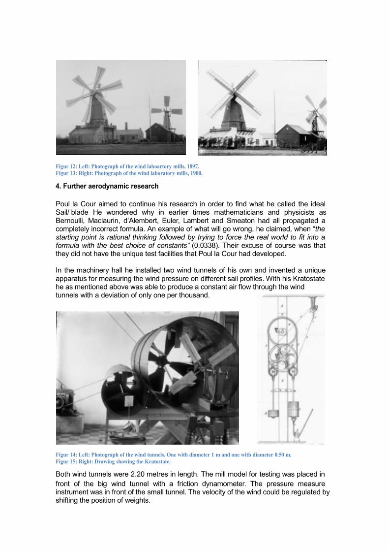
Poul la Cour aimed to continue his research in order to find what he called the ideal Sail/ blade He wondered why in earlier times mathematicians and physicists as Bernoulli, Maclaurin, d’Alembert, Euler, Lambert and Smeaton had all propagated a completely incorrect formula. An example of what will go wrong, he claimed, when “the starting point is rational thinking followed by trying to force the real world to fit into a formula with the best choice of constants” (0.0338). Their excuse of course was that they did not have the unique test facilities that Poul la Cour had developed. In the machinery hall he installed two wind tunnels of his own and invented a unique apparatus for measuring the wind pressure on different sail profiles. With his Kratostate he as mentioned above was able to produce a constant air flow through the wind tunnels with a deviation of only one per thousand.
Figur 14: Left: Photograph of the wind tunnels. One with diameter 1 m and one with diameter 0.50 m. Figur 15: Right: Drawing showing the Kratostate.
Both wind tunnels were 2.20 metres in length. The mill model for testing was placed in
front of the big wind tunnel with a friction dynamometer. The pressure measure instrument was in front of the small tunnel. The velocity of the wind could be regulated by shifting the position of weights.
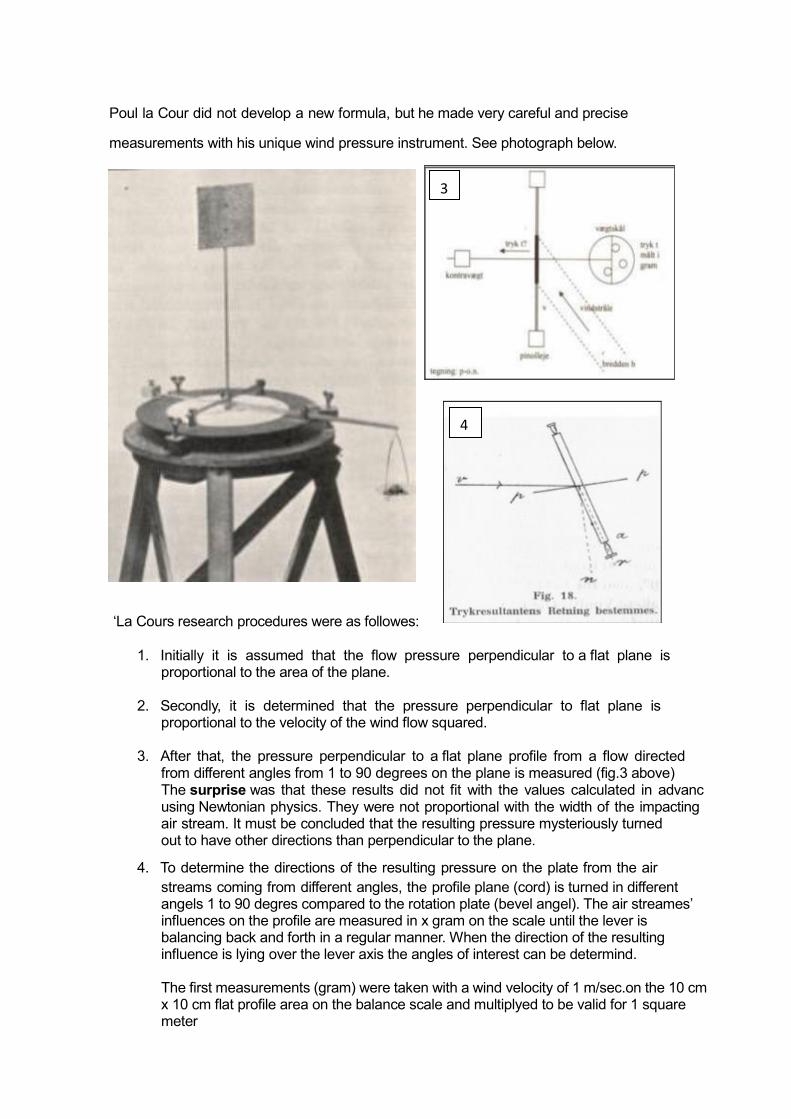
Poul la Cour did not develop a new formula, but he made very careful and precise
measurements with his unique wind pressure instrument. See photograph below.
‘La Cours research procedures were as followes: 1. Initially it is assumed that the flow pressure perpendicular to a flat plane is
proportional to the area of the plane. 2. Secondly, it is determined that the pressure perpendicular to flat plane is
proportional to the velocity of the wind flow squared. 3. After that, the pressure perpendicular to a flat plane profile from a flow directed
from different angles from 1 to 90 degrees on the plane is measured (fig.3 above) The surprise was that these results did not fit with the values calculated in advanc using Newtonian physics. They were not proportional with the width of the impacting air stream. It must be concluded that the resulting pressure mysteriously turned out to have other directions than perpendicular to the plane.
4. To determine the directions of the resulting pressure on the plate from the air
streams coming from different angles, the profile plane (cord) is turned in different angels 1 to 90 degres compared to the rotation plate (bevel angel). The air streames’ influences on the profile are measured in x gram on the scale until the lever is balancing back and forth in a regular manner. When the direction of the resulting influence is lying over the lever axis the angles of interest can be determind. The first measurements (gram) were taken with a wind velocity of 1 m/sec.on the 10 cm x 10 cm flat profile area on the balance scale and multiplyed to be valid for 1 square meter
3
4
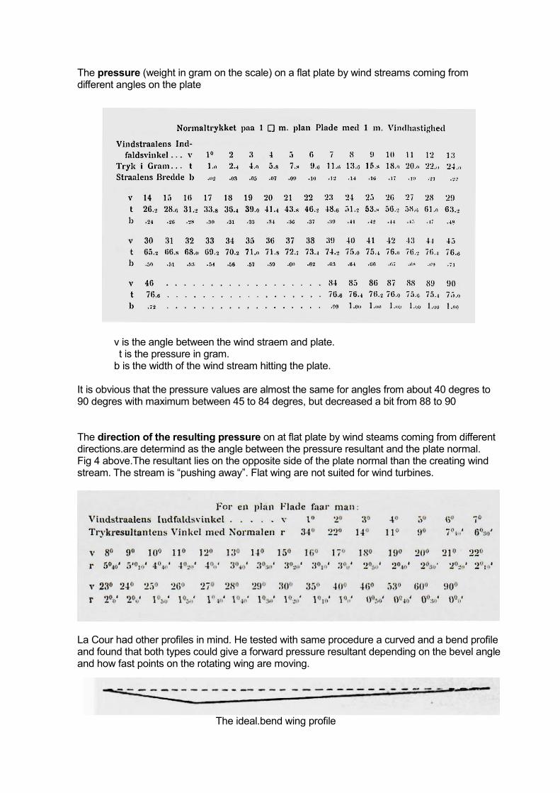
The pressure (weight in gram on the scale) on a flat plate by wind streams coming from different angles on the plate
v is the angle between the wind straem and plate. t is the pressure in gram. b is the width of the wind stream hitting the plate.
It is obvious that the pressure values are almost the same for angles from about 40 degres to 90 degres with maximum between 45 to 84 degres, but decreased a bit from 88 to 90 The direction of the resulting pressure on at flat plate by wind steams coming from different directions.are determind as the angle between the pressure resultant and the plate normal. Fig 4 above.The resultant lies on the opposite side of the plate normal than the creating wind stream. The stream is “pushing away”. Flat wing are not suited for wind turbines.
La Cour had other profiles in mind. He tested with same procedure a curved and a bend profile and found that both types could give a forward pressure resultant depending on the bevel angle and how fast points on the rotating wing are moving.
The ideal.bend wing profile
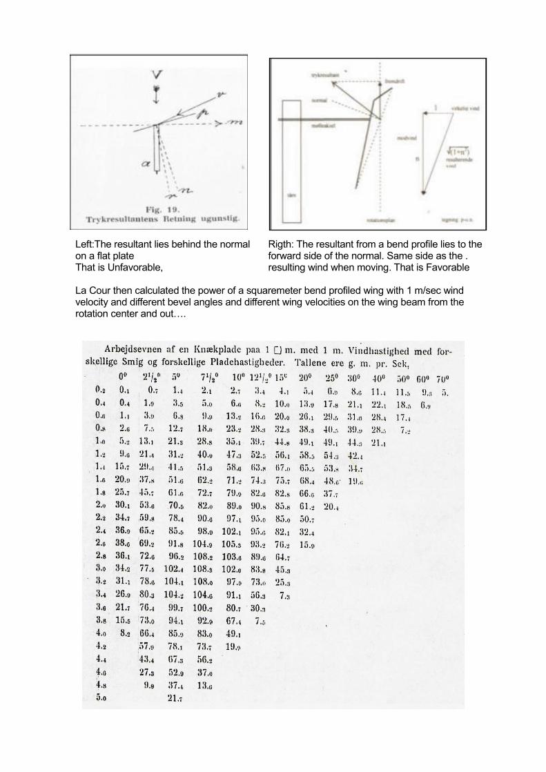
Left:The resultant lies behind the normal Rigth: The resultant from a bend profile lies to the on a flat plate forward side of the normal. Same side as the . That is Unfavorable, resulting wind when moving. That is Favorable La Cour then calculated the power of a squaremeter bend profiled wing with 1 m/sec wind velocity and different bevel angles and different wing velocities on the wing beam from the rotation center and out….
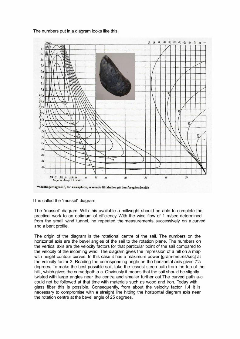
The numbers put in a diagram looks like this:
IT is called the “mussel” diagram The “mussel” diagram. With this available a millwright should be able to complete the practical work to an optimum of efficiency. With the wind flow of 1 m/sec determined from the small wind tunnel, he repeated the measurements successively on a curved and a bent profile. The origin of the diagram is the rotational centre of the sail. The numbers on the horizontal axis are the bevel angles of the sail to the rotation plane. The numbers on the vertical axis are the velocity factors for that particular point of the sail compared to the velocity of the incoming wind. The diagram gives the impression of a hill on a map with height contour curves. In this case it has a maximum power [gram-metres/sec] at the velocity factor 3. Reading the corresponding angle on the horizontal axis gives 7½ degrees. To make the best possible sail, take the lessest steep path from the top of the hill , which gives the curvedpath a-c. Obviously it means that the sail should be slightly twisted with large angles near the centre and smaller further out.The curved path a-c could not be followed at that time with materials such as wood and iron. Today with glass fiber this is possible. Consequently, from about the velocity factor 1.4 it is necessary to compromise with a straight line hitting the horizontal diagram axis near the rotation centre at the bevel angle of 25 degrees.
The specifications of the ideal mill, translated as precisely as possible, is as follows:
a) 4 sails with as few resistant surfaces as possible, especially near the tip of the sail.
b) The width of the sail to be nearly ¼ or 1/5 of the length of the sail, and almost same width all over.
c) The surface of the sail starts at a distance from the axis of about ¼ of the sail length, so the surface is ¾ of the sail length.
d) The cross section of the sail profile is not a straight line, but bent at a point, which is ¼ or 1/6 from the fore edge and the fold is so strong, that it is 3 to 4 % of the chord of the profile, especially at the tip of the sail, however, near the axis it can be straight.
e) The bevel angle is calculated from the profile chord, not from the large sail surface, nor from the small sail surface. It is 10 degrees at the sail tip and increases regularly so it is 15 degrees at 2/3rds of the distance from the axis and 20 degrees 1/3rd from the axis and would be 25 degrees at the axis.
f) The mill should be arranged so that the tip of the sail runs with a velocity factor of 2.4 the velocity of the incoming wind, out of which it is desirable to extract the greatest possible power. (It will most commonly be near to 6 or maybe only 5 metre/sec).
g) The work that such a mill produces can be calculated as the research shows, by the fact that there is 60 gram-metre per square metre sail surface at a wind velocity of 1 metre/sec. The work will be a factor 60 of the total sail area in square metres multiplied by the wind velocity cubed and will be expressed in gram-metres. By dividing this number with 1000 the value in kilogram-metre per sec will be determined. Divided again by 75 will give the answer in horse power. Example: If the 4 sails have a length of 8 metres and a width of 2 metres and the power at wind velocity of 6 meters per sec is to be determined, then the tip velocity is 6 times 2.4 = 14.4 metres/sec. And while the circumference will be about 50 metres, this mill will make (14.4 x 60)/50 = 17.3 turns per minute. Its sail surface is 4 x 6 x 2 = 48 square metres, and its power with the aforementioned wind is 60 x 48 x 6
3 = 622080 gr. m. = 622 kg. m. = 8.3 hp.
After publishing his research report “Forsøgsmøllen I og II” (The Research Mill I and II) in 1900, la Cour initiated a contest urging millwrights to build the ideal mill. Some of them became very angry as they were convinced they were already doing that! Millwright Chr. Sorensen was especially angry, because his attractive conical rotor on the laboratory building had, in the meantime, been exchanged for an ordinary 4 sail rotor (Figures 7 and 8). The problem was that the conical rotor in this large size had been too heavy and unstable. But Sorensen would not accept the removal and caused a lot of trouble in public, which finally involved the Danish parliament. The finances became limited. The end result was that in future the State Wind Laboratory should be a centre for information about the development and use of electricity in the rural areas of Denmark. A Danish Wind Electricity Society was formed and a consultant office was established. A magazine “Tidsskrift for Vind-Elektrisitet” was published 4 times a year. And finally, the training of so-called “Country Electricians” (Landlige Elektrikere) began in 1904 and was repeated every year until 1916.

Figur 23: Left: Photograph of the first class of Country Electricians from 1904. 24: Right: Design of an electricity producing wind mill for farms, recommended by la Cour.
Figur Figur 25: Left: Johannes Juul. enlarged from the 1904 team photograph. Figur 26: Right: Photograph of the Gedser turbine. The first 3-wing AC mill with tip safety brakes.
One of the students, Johannes Juul, was only 17. But the number 7 of his birth year
1887 looked very much like a 4 (1884) on his application, so the impression was given that he was old enough to participate. Of course this was discovered and after an extra year of practice he also received his diploma. He carried out further studies and became high voltage engineer, invented electric household equipment, and finally, in the 1950s, he developed the first 3-sailed AC wind turbine, the Gedser turbine. This was the “mother” of what is seen all over the world today, showing the influence from Denmark on the rest of the world.
3. Conclusions Poul la Cour published “Forsøgsmøllen III and IV” in 1903, as a supplement to his report of 1900. He admitted that his expression “The ideal Sail” was unfortunate, because it could be misunderstood as a claim to its invention which would upset some people. The phrase was only used to point out the importance of the right shape and the right bevel angle. He also admitted that hundreds of years of millwrighting experience provided sails that were close to the ideal, but seldom 100% correct. He invited mill owners to send him descriptions and dimensions of their mills and offered to advise them on any improvements. He also discussed the ratio between the length and width of the sails compared to the space between them. However, it was not until 1919 that a new formula was presented by Albert Betz. He showed that the power of a mill depends on the proportion of the circle area covered by the rotor – not the frontal area of the sails. Betz also calculated that the theoretical and practical limit would be 59% of the wind power available. The contribution of Poul la Cour was an important step on the road to understanding the force of vacuum lift on mill sails. It was discovered on mill sails 5-6 years before the Wright brothers became flying, although it is the same force that keeps an aeroplane in the air. As far as we know the “musseldiagram” was constructed by Poul la Cour and thereby introduced the new concept of the tip velocity ratio, which is commonly used in descriptions of modern wind turbines.

Poul la Cour died from a lung infection on 24th April, 1908. His contribution to knowledge in many fields was outstanding. He covered every step from fundamental theoretical to practical research, making inventions and implementing his ideas for the good of society. In addition he was the author of several text books such as “Historical Mathematics” and “Historical Physics”. As well as being a scientist, he was also a very religious man and felt no contradiction in that. His epitaph, carved in a memorial stone at Skibelund Krat a few kilometers south of Askov, expresses that: “As Light from Heaven gives Light to our Eye Thoughts are inspired by Light from on High”.
Science and Faith are complementary Bibliography Poul la Cour, Forsøgsmøllen I og II, Det nordiske Forlag, København, 1900. H.C. Hansen, Poul la Cour – grundtvigianer, opfinder og folkeoplyser, Askov Højskoles Forlag, 1985. ISBN 87-88765-01-6. Povl-Otto Nissen, Kratostaten – en opfindelse af Poul la Cour, Poul la Cour Museets Venner, 2004, ISBN 87-988859-2-8. Povl-Otto Nissen, Vindtunnelerne i Askov, Poul la Cour Museets, Venner, 2004, ISBN 87-988859-3-6. Povl-Otto Nissen, Poul la Cour og vindmøllerne, Ideernes Bagmænd, Polyteknisk, 2003, ISBN 87-502-0951-5. Informations from documents in the archive of the Poul la Cour Museum. The author
Povl-Otto Nissen, cand.edu.physics, is the former senior lecturer at Ribe State College of Education, 1979-2000. He was Principal of a Danish college for youth Education (højskoleforstander), 1975-1979 Since 2000 he has been chairman of The Friends of the Poul la
Cour Museum, and heavily engaged in developing the content and the activities at the museum. In this position he is the author of everal papers on the history of technology and biographies of Poul la Cour and Conrad Wilhelm Röntgen. Web site: www.povlonis.dk.