THE STATE OF THE ART IN GAS CLEANING FOR THE FERTILIZER ... · Urea Prill Tower – Case History #...
17
THE STATE OF THE ART IN GAS CLEANING FOR THE FERTILIZER INDUSTRY BY GEORGE C. PEDERSEN, PRESIDENT KIMRE, INC. PRESENTED AT THE ARAB FERTILIZER ASSOCIATION JUNE 25 – 27 2001 ALEXANDRIA, EGYPT
Transcript of THE STATE OF THE ART IN GAS CLEANING FOR THE FERTILIZER ... · Urea Prill Tower – Case History #...

THE STATE OF THE ART
IN GAS CLEANING
FOR THE FERTILIZER INDUSTRY
BY
GEORGE C. PEDERSEN, PRESIDENT
KIMRE, INC.
PRESENTED AT
THE ARAB FERTILIZER ASSOCIATION
JUNE 25 – 27 2001
ALEXANDRIA, EGYPT

TABLE OF CONTENTS
INTRODUCTION................................................................................................................................................................3GAS CLEANING ................................................................................................................................................................3GAS CLEANING MECHANISMS (Fig. 1)........................................................................................................................4
Inertial Impaction .............................................................................................................................................................4Interception ......................................................................................................................................................................4Brownian Capture or Diffusion........................................................................................................................................4Gas Absorption.................................................................................................................................................................5
Figure 3: Counter-current mass transfer – general case.......................................................................................................5WET SCRUBBERS.............................................................................................................................................................6
Spray Scrubber (Simple/Cyclonic/Water Impact) ...........................................................................................................6Packed Tower...................................................................................................................................................................7Venturi Scrubber (Venturi Cyclonic and Coaxial)...........................................................................................................7Cross / Semi-Cross Flow (SXF™) Scrubber ..................................................................................................................7
“KIMRE” LADDER-LIKE MASS TRANSFER MEDIA (KON-TANE® / B-GON®) ..................................................10STYLE* .............................................................................................................................................................................10WET SCRUBBER SELECTION ......................................................................................................................................11WET SCRUBBER APPLICATIONS IN THE FERTILIZER INDUSTRY .....................................................................11
Ammonia........................................................................................................................................................................11Nitric acid.......................................................................................................................................................................11Ammonium nitrate/CAN/NPK.......................................................................................................................................12Industrial Experiences....................................................................................................................................................12
INSTALLATIONS AND CASE HISTORIES ..................................................................................................................12Urea Granulation Plant – Case History # 56..................................................................................................................12Urea Granulation Plant – Case History # 57..................................................................................................................13Urea Prill Tower – Case History # 58............................................................................................................................13NPK Tail Gas Scrubber – Case History # 59.................................................................................................................13Phosphoric Acid Plant Fume Scrubber – Case History # 60 .........................................................................................14Phosphoric Acid Plant Fluorine Scrubber – Case History # 61 .....................................................................................15Phosphoric Acid Plant Vacuum Cooler Pre-Condenser – Case History # 62................................................................15
CONCLUSIONS................................................................................................................................................................16REFERENCES...................................................................................................................................................................17
INTRODUCTIONThe fertilizer industry has earned recognition for having contributed directly to increase world grain yields in the past century.Based on the conservative estimate of the world population growth, total fertilizer use in the future is expected to grow morethan 200 million tons from the current level of 165 million tons. In U.S.A. and other countries the industries have alwaysbeen challenged to meet the current and future air quality emissions standards set by local/state/federal governments under theClean Air Acts and other regulations.
Accordingly, less polluting technologies emerged by way of reducing SOx and NOx in exhaust air from the Sulfuric andNitric/Ammonia/Phosphate/Nitro-Phosphate plants in order to minimize “acid rain” problems in the atmosphere.
Fluoride emissions have similarly been lower from phosphoric acid /Di and Mono-Ammonium Phosphate, Granular Triple orSingle Super Phosphate plants at or below 0.02 lbs. F per ton P2 O5 input by scrubber technology and control mechanisms sofar. Further advances in technology for developing ladder-like structured mono-filament media as a packing material forabsorption and mist elimination purposes have reduced its level from 0.02 to 0.013 lbs. F- or less per ton in the industry atpresent.
This paper will discuss about gas cleaning equipment in general and advances in cross/semi-cross flow scrubber technologywith KON-TANE® / B-GON® / AEROSEP® in particular, as a packing media for prevention of air pollution in the fertilizerindustry.
GAS CLEANINGThe primary purposes of gas cleaning are:• Recovery of raw materials and products/by-products.• Meet present and future pollution emission standards set by the local, state and federal governments and/or other
regulatory agencies.• Minimize ozone depletion by reducing fluorine SOx, NOx, levels in air.
The phosphate fertilizer industry covers different chemical processes in order to manufacture phosphoric/fluosilicic acids anddifferent products. This generates off-gases and particulate matter from various steps during the process e.g.
• Reaction • Granulation• Filtration • Drying/Cooling/Screening• Clarification • Product storage/handling• Evaporation • Crushing/Grinding/Reclaiming
Different types of gas cleaning (dry and/or wet) are adopted depending upon types and size of particles/gaseous componentspresent in vent air as liberated from the operating units in the process. Also, handling characteristics, electrical properties,wetability, toxicity and flammability are some of the particle properties that are taken into account for design and operationpurposes.
Dust collectors, e.g. cyclones, are utilized to recover large size particles in gaseous effluents greater than 10µm whereas fabricfilters (bag-house) and electrostatic precipitators can be considered to remove small size particles less than 10µm size fromdust laden air in the process.
In addition, wet scrubbers of different types are used for final cleanup of particles and pollutants from the process vent gasesbefore it is emitted to the atmosphere.

GAS CLEANING MECHANISMS (Fig. 1)• Inertial Impaction• Interception• Brownian Capture or diffusion• Gas Absorption
Inertial impaction and Interception are the predominant mechanisms of particulate capture in wet gas scrubbers for larger sizeparticles (> 1 µm in size) whereas Brownian diffusivity of particles increases as size decreases and so, removal mechanism ismost important for smaller particles (< 1 µm).
Inertial ImpactionInertial impaction results often as the particle fails to follow the rapidly curving stream lines around a droplet or obstacle andcontinues to move toward the droplet along a path of less curvature due to inertia. Inertial impaction relates to the collectionof particles on small droplets whereas, inertial impingement relates to the collection of particles on large surface or into liquid,whereby gas stream carrying the particles is small.
InterceptionThe mechanism of collection of particles by interception depends on size of the particles rather than on its mass or inertia.The particles, in this case, follow a gas stream line around the droplet and interception occurs as they pass half the distance ofparticle diameter (Dρ) away from the droplet surface. Thus, collection by interception is a function of interception parameters(KI = Dρ/Dƒ, Dρ = particle diameter, Dƒ = fiber diameter) and Reynolds number. Single-fiber efficiency can be calculatedbased on an empirical formula in the turbulent region (Ref. 2) .
Brownian Capture or DiffusionBrownian capture results when smaller particles below <1 µm size do not move along the gas streamline and diffuse from thegas to the surface of the droplet and get captured. This particular type of separation mechanism is more applicable for mistelimination purpose in order to achieve 99.98% separation efficiency for 0.3µm and below particle sizes. Particle removal byBrownian diffusion and gravitational separation is usually absent due to high velocity and low ‘hold-up’ time available.
Figure 1: Mechanisms of Collection

Gas AbsorptionThe mechanism of gas cleaning by absorption of soluble pollutant gases in a liquid relates to mass transfer equation fortransfer unit calculations shown below
Only for linear equilibrium lines with linear operating lines (Figure 2).
Also, the height of transfer units (HTU) or packing height(Z) can be determined from a knowledge of overall gas masstransfer coefficient (Ky) and gas mass flow rate (Gy) per unit cross sectional area as commonly expressed by
Linear systems are infrequent in fertilizer plants (Figure 3).
However, where the equilibrium solubility of polluted gas in a particular liquid is not known, a cooling tower type calculationcan be used based on enthalpy balance of a specific scrubber chosen assuming adiabatic saturation process takes place.
Figure 2: Counter-current mass transfer – simple case.
Figure 3: Counter-current mass transfer – general case.
ÁË
Ê ÁË
Ê--=
-Ú ln
* 2Y*Y*Y
1YYY
dYNTUwhere NTU = Number of Transfer Units
Y1, Y2 = Initial and final concentration of solute gasY* = Equilibrium concentration of solute in gas
dy
Kya
GyZ NTUHTU ¥== Ú
Y2
Y1YY - *
Y1
Y2
=
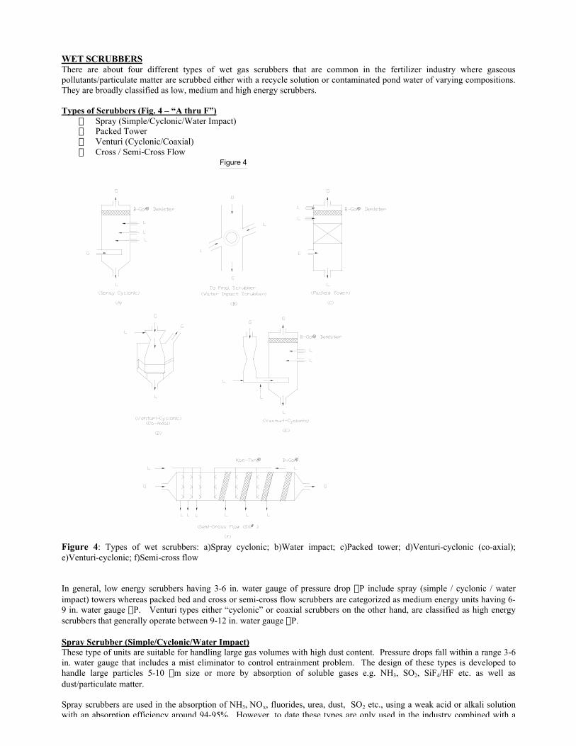
WET SCRUBBERSThere are about four different types of wet gas scrubbers that are common in the fertilizer industry where gaseouspollutants/particulate matter are scrubbed either with a recycle solution or contaminated pond water of varying compositions.They are broadly classified as low, medium and high energy scrubbers.
Types of Scrubbers (Fig. 4 – “A thru F”) Spray (Simple/Cyclonic/Water Impact) Packed Tower Venturi (Cyclonic/Coaxial) Cross / Semi-Cross Flow
® ®
®
™® ®
Figure 4
Figure 4: Types of wet scrubbers: a)Spray cyclonic; b)Water impact; c)Packed tower; d)Venturi-cyclonic (co-axial);e)Venturi-cyclonic; f)Semi-cross flow
In general, low energy scrubbers having 3-6 in. water gauge of pressure drop DP include spray (simple / cyclonic / waterimpact) towers whereas packed bed and cross or semi-cross flow scrubbers are categorized as medium energy units having 6-9 in. water gauge DP. Venturi types either “cyclonic” or coaxial scrubbers on the other hand, are classified as high energyscrubbers that generally operate between 9-12 in. water gauge DP.
Spray Scrubber (Simple/Cyclonic/Water Impact)These type of units are suitable for handling large gas volumes with high dust content. Pressure drops fall within a range 3-6in. water gauge that includes a mist eliminator to control entrainment problem. The design of these types is developed tohandle large particles 5-10 mm size or more by absorption of soluble gases e.g. NH3, SO2, SiF4/HF etc. as well asdust/particulate matter.
Spray scrubbers are used in the absorption of NH3, NOx, fluorides, urea, dust, SO2 etc., using a weak acid or alkali solutionwith an absorption efficiency around 94-95%. However, to date these types are only used in the industry combined with a

Packed TowerThis type of scrubber is most suitable for gas absorption rather than dust or particle collection utilizing mass transfer betweena liquid and a gas stream flowing counter current wise through a specific packing material. Packed towers have been verycommonly used in the fertilizer industry due to high efficiency at increased ‘∆P’ in order to meet the present environmentalpollution standards.
The absorption efficiency may drop due to quality of scrubbing liquid and type of packing material selected because of solids‘build-up’ as common as in the fertilizer industry.
Venturi Scrubber (Venturi Cyclonic and Coaxial)Both venturi cyclonic and coaxial types have been in use in phosphoric acid and DAP/MAP/GTSP plants for handling dirtygas loaded with dust and particulate matter at a pressure drop varying between 6-12 in. water gauge ∆P.
Additional pressure drop of 5 in. water gauge is required to reduce dust concentration from 0.06 to 0.03 gr/scf equivalent to135 mg. to 65 mg/Nm3 depending on particle size of the specific dust, fume or mist to be removed and absorption efficiencyof SOx , NOx, NH3 desired. The mechanism of particle collection in the venturi scrubber is known to be by inertia impactionfollowed by mass transfer of soluble component from gaseous to liquid phase.
Cross / Semi-Cross Flow (SXF™) ScrubberA Cross or Semi-Cross flow (SXF™) Cross Flow Scrubber has been found to be the most successful applications inPhosphoric acid, DAP/MAP/TSP/SSP fertilizer processes for the past twenty-twenty five years with an advanced technology ,see Fig. 4G, H, and I (Ref. 4) .
Figure 4G: SXF scrubber, once-through water
Figure 4H: SXF scrubber, counter-flow liquid, with cooling, chemicals, and waste stream addition (tower packing and mistelimination as in Figure 4G.
This type of wet scrubbers is developed as a combined unit of a spray and packed bed sections housed horizontally in a boxwith a mist eliminator inside for maximum separation of soluble gases, particulate matter and mist particles below 0.5 µmsize. They are classified under medium energy scrubbers having a pressure drop (∆P) 6-9 in. water gauge unlike packedtowers or venturi cyclonic/coaxial scrubbers when used separately.
ConditioningSprays
Stages 1 & 2KON-TANE®
Tower Packing
Stages 3 & 4B-GON®
Mist Eliminator

Figure 4I: SXF scrubber for absorption, fog, and solids collection followed by AEROSEP® Multi-Stage Aerosol SeparationSystem for sub-micron aerosol collection.
Design of ‘Cross’ or ‘Semi-Crossflow (SXF™) scrubbers includes the following (Figure 5, Ref. 5) : Pre-cooling/Wetting/Pre-cleaning of particulate matter and gaseous effluents. Humidification/Cooling/Separation of medium to large size particles of approximate 94-99% efficiency between 5mm-
50mm size and soluble gases. Stage-wise absorption of soluble gases and fine to medium size (between 1-5mm) particulate matter using interlaced,
ladder like structured filament media e.g. KON-TANE®. Final separation of fine (<1mm) size particles as mist and ‘aerosol’ particles using B-GON® filament media of finer
styles but similarly structured like KON-TANE® in order to achieve 99.7%-99.9% recovery (Figure 6) .
Figure 5: Enthalpy calculations SXF, once-through water.
Airflow
ConditioningSprays
Stage 1
KON-TANE™
Stage 2
KON-TANE™
Stage 3
B-GON™
Stage 4
B-GON™Stage 1 Stage 2 Stage 3 Stage 4
99% @
3 Microns
Particle Growth
99% @
1 Micron99% @
10 Microns

Figure 6: Illustration of the collection efficiency of B-GON® Mist Eliminator.
The authors have presented several papers comparing SXF semi-cross flow contactors with counter-flow dumped packingcontactors, which show substantial differences (Pedersen & Bhattacharjee, 1996).
Regrettably, the differences between counter-flow contactors and SXF cross-flow, or other semi-cross-flow, or cross-flowcontactors, has not been covered in the general literature nor at the university level so there is little familiarity with theapplicable concepts. The lack of use, and lack of familiarity, is unfortunate because cross-flow or semi-cross-flow contactorsoffer characteristics which are very beneficial in many situations (Table 1).
Table 1: Comparative summary between SXF and counter-flow packed bed scrubbers.ITEMS VERTICAL COUNTER-FLOW HORIZONTAL SEMI CROSS-FLOWDESIGN CONSIDERATIONSHeat Effects Handled only with difficulty Easily Handled based on well established cooling principles
with stage-wise cooling or heating of the liquid.External Liquid to Gas Ratio (L/G) Does not work at low L/G. Problem of flooding
and entrainment occur at very high L/G andtheoretical NTU limited by packing (Dumped)types
No lower limit on external L/G. High ext.L/G can be used,if required, but is usually not necessary since moretheoretical NTU’s are Available.
Stage L/G N/A Independently ControlledStages of Absorption in Each Vessel Single MultipleSolution Recovery Single dilute concentration is feasible. Different concentration levels from high to low are feasible.Gas and Liquid Inlet Concentration Applications only for Steady State slowly changing
conditions.Applications for non-steady state and highly variableconditions.
Area of Installation Less MoreFlexibility Less MoreSize and Shape Circular Rectangular or CircularPacking Regular “Intalox” saddle/ Rachig or Pall Rings,
etc…KON-TANE® Tower Packing
Pressure Drop Low LowEfficiency Highly Variable HigherAPPLICATIONSSensitivity to Component Failure Dramatically affected Less affected. Unit capability can be restored quicklyAdaptability Less MoreMaintainability Hard due to removal of all packing at one time.
On-Line maintenance is not recommendedEasy due to lighter packing weight and easy removal fromone-stage both labor and time- wise. On-line maintenancearrangement can be built in, ie. No shut downs formaintenance.
Multi-Functionality Minimum Maximum and so enables to handle many applicationsCOSTInstalled Basic HigherOperating Higher Lower
80
85
90
95
100
105
2 3 4 5 6 7 8 9 10 11
Drop Size (microns)
Co
llect
ion
Eff
icie
ncy
(%
)
Max. Flowrate
Min. Flowrate

In summary, SXF contacting concepts can be used for:• Direct contact heat transfer, and/or• Mass transfer to any level of removal, and/or• Mist elimination and/or particulate scrubbing to 1µm (and with the addition of AEROSEP technology, to sub-
micron)
Most importantly, for any combination of the above, the functionality of the technology provides the benefit of “lowest-cost-per-ton-of-production” at a given performance level.
The higher fluorine recovery or lowering of fluoride pollution emission in air at or below 0.013 lb. Per ton P2 O5 input hasbeen proven in the fertilizer industry for past several years in many places within U.S.A., Canada, Europe, Japan and otherAsian and South American Countries utilizing Kimre™ advanced technology.
“KIMRE” LADDER-LIKE MASS TRANSFER MEDIA (KON-TANE® / B-GON®)In gas cleaning, there is clearly a trade-off between contaminant removal efficiency vs. energy consumption based on pressuredrop (∆P) applied in the process. But, the trade-offs between technologies are not sometimes clear if benefits of removalefficiency are not recovered fully well.
Years of long service in the U.S. and other countries with “Kimre” mass transfer media technology have given a strongreputation in gas cleaning within the fertilizer and other industries. This unique technology provides superior particleelimination from the process at a low pressure drop within 6-7 in. water gauge.
The unique interlacing media is available in a variety of coarseness or styles (Table 2).
Table 2: Styles of available Kimre mass transfer media
STYLE* USE
2/96 Ultra – high – plus efficiency mist elimination and/or coalescing with 50 micron filaments.
4/96 Ultra – high – efficiency mist elimination and/or coalescing with 100 micron filaments.
8/96 Very-high efficiency mist elimination and/or coalescing With 200 micron filaments.
16/96 High-efficiency mist elimination with 400 micron filaments.
16/97 Like 16/96 with improved liquid handling.
37/94 Mist elimination and tower packing for dirty service.
37/97 Mist elimination and tower packing for extremely dirty service and high velocities.
* The left-hand number identifies the filament diameter in 0.001 inches.The right-hand number is the approximate percentage of free void space.These styles are standard. Other variations are available on special order.
Different styles can be combined in a single pad to provide the optimum performance based on particulate separationefficiency, pressure drop vs. cost, etc.
The ladder-like structured monofilament media (see Figure 7) creates sufficient flow turbulence to cause intimate gas-liquidmixing over maximum contact surface areas available for• Mass transfer and• Particle separation by inertial impaction, interception and Brownian diffusion to take place with high recovery of
particulate matter and pollutants in vent air.
“Kimre” monofilament media KON-TANE® utilizes the combined effects of three mechanisms to maximize phase separationand particle collection efficiency by providing sufficient drainage of liquid through a predetermined void space depending onapplication to application.

These pads can be configured according to different functions:• Removal of heavy liquid load by proper drainage• Plugging resistance to avoid blinding• Coalescing or removal of small particles coalescing of small (0.8-3µ) to large (10 +µ) droplets.• Entrainment separation for removal of large particles using B-GON® media.
The effectiveness of one layer of any type B-GON® mist eliminator can easily be calculated on proprietary software.
Liquid removal from mist eliminators should operate below the flooding point as determined from the Sherwood Shipley-Holloway correlation and pressure drop for a single layer of media can be calculated from an empirical equation.
The pressure drop across B-GON® pads has been experienced around 1” ∆P water gauge.
The pads of different styles and combinations are provided in rectangular or circular frames suitable for a particular designand shapes of a scrubber vessel. For ease of operation and maintenance purposes, “Pants Hanger™” types have become verypopular in the industries lately by utilizing in semi-cross SXF™ scrubbers for Phosphoric acid, SSP/GTSP/DAP/MAPapplications.
Figure 7: Exploded view of B-GON® Mist Eliminator.
WET SCRUBBER SELECTIONChoosing a scrubber largely depends on the following criteria for a particular air pollution problem in the fertilizer industry.• Process• Type of contaminants/characteristics• Separation efficiency• Design considerations for:
a) Single or stage-wise absorptionb) Packing typec) Pressure dropd) Liquid (L) to Gas (G) ratioe) Solution recoveryf) Temperature change
• Flexibility of operation/maintenance• Costs (installation and operation)• Performance history
WET SCRUBBER APPLICATIONS IN THE FERTILIZER INDUSTRYThe major contaminants for air pollution in the fertilizer industry are NH3, NOx, SOx, Fluorides, Ammonium nitrate, Ammoniumphosphate, Urea, Superphosphates (Normal/Triple) and NPK dusts.
AmmoniaAmmonia process uses a high and low pressure spray type water scrubbers with a mist eliminator to recover 95%-96%ammonia. This can further be improved with a filament type B-GON® mist eliminator as proven in other processes.
Nitric acidNitric acid process can utilize similar type droplet separators in order to lower NOx emission levels below 100 ppm.

Ammonium nitrate/CAN/NPKprocesses have been using packed column or venturi cyclonic scrubbers and a demister for removal of ammonia less than 15mg/Nm3. However, removal of sub-micron ammonium nitrate particles can be difficult using regular scrubbing methods ashave been experienced in Urea and Mono/Diammonium Phosphate (MAP/DAP) processes.
To reduce emissions of ‘aerosols’/sub-micron particles in air, cross/semi-cross flow scrubbers using KON-TANE®/B-GON®/AEROSEP® Filament type media have been found most suitable for dealing with the following:
 High dust loads ‘Aerosol’/sub-micron size (NH4 NO3, NH4F/NH4 HF and other reaction products in gaseous phase) High air volumes from prilling/granulation Fugitive ammonia/fluoride gases Unstable operating conditions Increased maintenance problems Low operating cost Most stringent air pollution limits under the current and proposed U.S. Clean Air Quality Act.
Industrial ExperiencesA. Proven applications related to Phosphate fertilizers/Acids plants include the following:
 Rock Dryer: B-GON® Mist Eliminator for maximum rock particle recovery. Fume Scrubbers: KON-TANE® packing followed by B-GON® Mist Eliminator for maximum fluorides and
particulate recovery worldwide. Fluosilicic Acid (FSA) Scrubbers: B-GON® Mist Eliminator for fluorides recovery. Evaporators: B-GON® Mist Eliminator for P2O5 recovery. Ammonium Phosphate/Single/Triple Super Phosphate Scrubbers: Widely used with KON-TANE® packing media
followed by B-GON® Mist Eliminator in cross/semi-cross flow (SXF™) scrubbers for chemical recovery andminimum fluorides/particulates in exit air in Australia, Brazil, Canada, China, France, India, Philippines, S. Korea,U.S.A., etc.
 Sulfuric Acid Absorption/Drying Tower: B-GON® Mist Eliminators offer superior efficiency in U.S.A. and abroad.
B. Retrofit applications related to the Nitrogenous fertilizer industry have proved B-GON® media to be: Less susceptible to fouling Easy to clean and Able to reduce droplet and particulate entrainment from Ammonium Nitrate and Urea, granulation and prilling towers
in U.S.A.
INSTALLATIONS AND CASE HISTORIESA selection of installations in phosphoric acid and phosphate fertilizer is listed in the Appendix. This is about one half of suchinstallations. Similar information is available for nitrogenous fertilizers and sulfuric acid production.
Urea Granulation Plant – Case History # 56At BP Chemicals Urea Plant in Lima, Ohio, USA, process gas from a granulator is routed to a venturi scrubber followed bychevrons to reduce particulate matter and ammonia emissions. The existing venturi scrubber and chevron mist eliminators wereinstalled with poor flow distribution. The limited space in the vessels lead to re-entrainment through the chevrons in areaswhere the velocity exceeded the maximum operating velocity of the chevrons. In addition to the poor flow distribution, thechevron mist eliminators were experiencing problems with pluggage. The flow rate through the mist eliminators was over 1000fpm (5.1 m/s).
51
Figure 8Urea Granulation Scrubber
B-GON® MistEliminator
Chevron

An inclined B-GON® Mist Eliminator was recommended to replace both of the banks of chevrons. However, based on thecustomer’s preferences, Kimre designed a single-stage B-GON® Mist Eliminator to replace the first-stage chevron (Figure 8).The mist eliminator was assembled with varying concentrations of media to re-distribute the air flow to the final stagechevron. The mist eliminator is over 90” tall x 94” wide (2280mm H x 2390 mm W). The flow through the vessel is over76,000 ACFM (129,000 Am3/hr) and the pressure drop through the mist eliminator is between 2-4” WC (50-100 mm WC).
The granulator scrubber was retrofit in 1995. Since this installation the emissions are acceptable and the re-entrainmentproblem has been solved. In addition to correcting the flow-distribution, the B-GON® Mist Eliminators have improved thecollection efficiency of droplets down to 10 microns in diameter.
Urea Granulation Plant – Case History # 57At BP Chemicals Urea Granulation Plant in Lima, Ohio, process gas from an evaporator and granulator scrubber is routed to aduct scrubber to reduce particulate matter and ammonia emissions.
In 1998, Kimre, Inc. was contacted for a new project at the urea granulation plant. The previous successes at the plant leadthe customer to contact Kimre, Inc. for the project. The plant was applying for an expansion project and needed to meet a 5.4kg/hr particulate matter (PM) and extremely low ammonia emission limit.
An agglomerator B-GON® Mist Eliminator with significant amounts of some of Kimre’s finest media was recommended toreach the new requirements. The mist eliminator was supplied in Batten Bar™ Media Holding Systems to ensure propersealing across the agglomerator stage. The engineering firm that contracted Kimre, Inc. to design the mist eliminator installedthe B-GON® Mist Eliminator in the 3650 x 3650 mm scrubber in between banks of chevron mist eliminators.
The duct scrubber successfully achieves an average emission of 0.3 kg/hr of PM at a flow rate of 109,000 Nm3/hr. The planthas decided not to go through with the planned expansion and is satisfied with the lowered ammonia and urea emissions.Before the installation of the B-GON® Mist Eliminator System, the urea emission was higher than 6.45 kg/hr. Based on thelow emissions and the changes in expansion plans, the plant has modified the configuration of the agglomerator stage,resulting in lower pressure drops, higher throughputs, and insignificant changes in PM emissions.
Urea Prill Tower – Case History # 58Repeated success at the BP Chemicals Urea Granulation plants in Lima,enabled Kimre, Inc. to discuss possible improvement in the 9.8 m Prill Towerwith the Engineering Department at BP Chemicals (Figure 9). An importantobjective of the team was to significantly increase the throughput of the tower.The pressure drop across the existing foam and knitted mesh mist eliminatorsprevented the customer from achieving this improvement in capacity.
Several reasons were cited by the customer for replacing the existing misteliminators:higher quality product, increased throughput, lower pressure drop,decreased emissions, and less maintenance requirements. In order to decidethe best B-GON® Mist Eliminator design for the installation, Kimre, Inc.worked with Lucas Process Systems and the local Kimre representative on apilot study. After running several tests in the tower, Kimre, Inc. recommendeda composite mist eliminator to be installed by others in a Batten Bar™ MediaHolding System.
The unique, interlocking structure of the B-GON® Mist Eliminators and thevariety of styles available enabled Kimre, Inc. to engineer a mist eliminatorcapable of lower pressure drops at higher gas velocities. The liquid handlingability of the mist eliminator was also improved with the addition of morecoarse styles of material to the design. The Batten Bar™ Media HoldingSystem improved the sealing of the mist eliminators in the tower andprevented the media from sagging due to the tall module heights.
NPK Tail Gas Scrubber – Case History # 59In 1997, Incro S.A. contacted Kimre to help meet design a scrubbing system that would meet the stringent Fluorine emissionlimits for Dongbu Hannong Chemicals NPK plant in Ulsan, South Korea. This project would prove to be an extremelyaggressive undertaking. The plant is designed to supply up to thirty different phosphatic grades to target the relatively shortseasons of the domestic small plot fertilizer market. Production runs would be fairly short. Process fluctuations would beextreme. Planned shutdowns were to be minimal.
Sprayhead Level Emission Control Modules,Sampling Locations
Elevator
Fluid BedLevel
Prill Conveyor Air Intakes
Urea Prill TowerElevation View
61 m
54
3
2
1
6
7
8
9
10
ElevatorPumpRoom
Emission ControlModules
Urea Prill Tower
Emission Control LevelPlan View
9.8 m Ø
Figure 9: Urea prill tower withmist eliminators

The design conditions for the Tail Gas Scrubber were as follows:§ Gas Flow Rate: 135,000 Am3/hr§ Temperature: 50°C§ Inlet Loadings: Dust = 300-1000 mg/Am3
Fluorine = 50-100 mg/Am3 (200 mg/m3 max)Ammonia = 50-300 mg/Am3
§ Outlet Guarantees: Dust = 90% removalFluorine = 3 mg/m3 (Outlet design = 2 mg/m3)Ammonia = 85% removal
Furthermore, the client required a ZERO LIQUID DISCHARGE FROM THE PLANT. This additional specificationunderstandably increases the constraints under which any type of scrubbing system operates.
Kimre proposed a system incorporating its SXF™ Semi-Crossflow Scrubber Technology to meet or exceed all of thespecified design requirements. The packing components would be installed in a vessel with a cross-section of 3800 mm H x5600 mm W. Kimre’s proposed system utilized three (3) stages of its KON-TANE® Tower Packing and one stage of B-GON® Mist Eliminator to achieve the desired results. The packing and mist eliminator stages were supplied in frames usingour Pants Hanger™ Media Holding System to allow for easy access to the media for on-line maintenance: The system cancontinue to operate IN COMPLIANCE while doing maintenance.
The low liquid discharge guarantee is met by utilizing counterflow stage-wise recirculation of scrubbing liquid. Thisoptimizes mass transfer driving forces with limited availability of scrubbing liquid by contacting the most concentrated liquidstreams with the most polluted gas, and the clean liquid streams with the least polluted gas. The effluent from the firstscrubbing stage was fed to venturi scrubbers directly upstream of the SXF™ Scrubber.
Kimre’s offer was contingent upon approval of vessel drawings and vessel construction according to specifications. Severaldays following order acceptance, it was revealed that vessel fabrication was already 80% complete and the optimum vesseldesign would not be possible. With startup less than three months away, Kimre was able to alter its design. The system withthe new modifications was delivered early, demonstrating the flexibility of the SXF™ System.
This system has been operational since 1997. Dongbu engineers report that the system continues to meet all performanceguarantees and has proven to be easy to maintain and operate. Further, the Kimre media has held up extremely well under awide range of operating conditions, and the client continues to operate the vessel with the original media intact andoperational.
Phosphoric Acid Plant Fume Scrubber – Case History # 60In March 1998, Kimre was invited to submit an offer for supply of towerpacking and mist eliminator components for the Oswal Chemicals & FertilizerLtd. (OCFL) project to develop three 2000 tpd DAP plants at its Paradeep,India location. Kimre’s technology would be utilized in the planned 2650 P2O5
tpd phosphoric acid plant - the world’s largest phosphoric acid plant to date.The design of the plant was provided by Jacobs Engineering Group, and itssubsidiary, Humphrey & Glascow Consultants Ltd., provided the detailedengineering and construction consulting. Jacobs Engineering required a TailGas Fume Scrubber for its phosphoric acid plant to meet a very low Fluorineemission limit.
The horizontal cross-flow scrubber fume scrubber, which utilized Kimre’sSXF™ Cross-Flow Scrubbing Technology, had the following designconditions:• Gas Flow Rate: 143442 Nm3/hr• Inlet Fluoride Loading: 7900 mg/m3
• Outlet Fluoride Emission: 8 mg/m3
The cross section of the fume scrubber is more than 11 meters wide x 3.6meters high. Kimre supplied three (3) stages of our KON-TANE® TowerPacking to provide the 99.9% scrubbing efficiency required and one (1) stageof our B-GON® Mist Eliminator to prevent entrainment of the droplets.
Each packing and mist eliminator stage was comprised of ten (10) packingmodules 2900 mm H x 874 mm W x 250 mm L (Figure 10). Thepolypropylene packing and mist eliminator media was supplied in modules ofAlloy 20, and utilized our Pants Hanger™ Media Holding System.
Figure 10: SXFTM modules

With the Pants Hanger™ Technology, the modules are easily installed and removed from the top of the scrubber formaintenance. Also, the technology allows direct access to the Kimre media for thorough cleaning.
Phosphoric Acid Plant Fluorine Scrubber – Case History # 61The Oswal Chemicals & Fertilizer Ltd. (OCFL) phosphoric acid plant, referenced above, included six (6) Fluorine Scrubbers,each with an inside diameter of 6400 mm and the following design conditions:
• Gas Flow Rate: 468,000 Am3/hr• Temperature: 45°C• Pressure: 58.4 mm Hg, absolute• Composition: water vapor with 4.5% Fluorine
The B-GON® Mist Eliminator Pads were to provide 99+% collection efficiency for all droplets 10 µm and larger. Kimreprovided mist eliminators in Style 37/97 to provide the maximum resistance to pluggage from silica scale, and the highestliquid handling capacity of any mist eliminator available.
Adding to the design complications, the vessels are rubber lined and, therefore, sensitive to temperature. If the pressure dropacross the pads were to increase excessively, the temperature in the vessels would increase excessively and could damage therubber lining. Therefore, the pressure drop across the mist eliminator was to be limited to a maximum of 50 mm WC at alltimes – even when pluggage of the mist eliminator occurs.
To meet this requirement, Kimre designed each of its mist eliminator with pressure-relief doors. The pressure relief doors arestrategically located across the pad’s cross-section (See Figure 11). Also, the doors are designed with a specific weight thatwould allow them to open when the pressure drop across the pad reached 50 mm WC. The doors would open, and allow thegas to bypass the material to avoid temperature excursions within the vessel. The entire construction was supplied in PP.
Figure 11: Fluorine scrubber mist eliminator with pressure relief doors.
Phosphoric Acid Plant Vacuum Cooler Pre-Condenser – Case History # 62The Oswal Chemicals & Fertilizer Ltd. (OCFL) phosphoric acid plant also includes three (3) Vacuum Cooler Pre-condensers,each with an inside diameter of 3800 mm and the following design conditions:
• Temperature: 77°C• Pressure: 292 mm Hg, absolute• Composition: water vapor with trace Fluorine
As with the Fluorine Scrubber (Case History 62) the B-GON® Mist Eliminator Pads were to provide 99+% collectionefficiency for all droplets 10 µm and larger. Kimre provided mist eliminators in Style 37/97, 100% PP construction to againprovide maximum resistance to plugging and avoid re-entrainment of droplets. Also, the mist eliminators were again requiredto keep a maximum pressure drop of 50 mm WC, even if becoming blocked with insolubles. Pressure-relief doors weresupplied to ensure this pressure drop limit was not exceeded.

Kimre supplied its components for the plant by May 1999. After many months of delays (including natural disasters), thephosphoric acid plant was started up successfully.
CONCLUSIONSAdvances in gas cleaning technology have been possible and practically proven by developments of theoretical ideas andintegrating it with ‘real-world’ experiences in the different chemical processes involved in the fertilizer industry.
Selection of a scrubber is critical to deal with increased dust load and sub-micron particles /’aerosols’ in order to avoid ‘bluehaze’ and other visible plumes in the stack and meet ‘BAT’/BACT’/BPEO’ under USEPA and European Community (EC)environmental legislations.
Cross/Semi-Cross flow scrubbers with ‘filament’ media (KON-TANE®/B-GON®/AEROSEP®) have been used successfully inAmNO3, Urea, Super/Triple and Mono/Diammonium phosphate and NPK fertilizer plants to meet world air pollution standardseither as a primary or secondary unit.
Present pollution prevention by implementing advanced gas cleaning technology has already led to fluosilicic acid solutionrecovery in super phosphate plants and thereby minimization of wastes and hazards in the fertilizer industry.

REFERENCES
1. “Air Pollution Control” Howard E. Hesketh Ann Arbor Science Publishers Inc.
2. “New Mist Eliminator for Improved Sulfuric Acid Plant Operation” G. C. Pedersen, Kimre, Inc.
3. Chemical Engineers Handbook, 5th Edition, Perry and Chilton.
4. “Fertilizer Phosphoric Acid Production: The Control of Fluoride Emissions” G. C. Pedersen, Kimre, Inc. and John Sinden, May 16, 1991, Liege, Belgium.
5. “Design Features for Fluorine Scrubbing in the Fertilizer Industry”
G. C. Pedersen, AIChE, Central Florida, U.S.A. Meeting, September 8, 1987.