The ‘Sphere’: A Dedicated Bifurcation Aneurysm Flow...
14
The ‘Sphere’: A Dedicated Bifurcation Aneurysm Flow-Diverter Device THOMAS PEACH, 1 J. FREDERICK CORNHILL, 2,3 ANH NGUYEN, 2,3 HOWARD RIINA, 2,3,4 and YIANNIS VENTIKOS 5 1 Institute of Biomedical Engineering, Department of Engineering Science, Oxford University, Oxford, UK; 2 Minimally Invasive New Technologies Program, Weill-Cornell Medical College, New York, NY, USA; 3 New York Presbyterian Hospital, New York, NY, USA; 4 Department of Neurosurgery, NYU Langone Medical Center, New York, NY, USA; and 5 Department of Mechanical Engineering, University College London, London, UK (Received 29 January 2014; accepted 15 July 2014; published online 26 August 2014) Associate Editor Ajit P. Yoganathan oversaw the review of this article. Abstract—We present flow-based results from the early stage design cycle, based on computational modeling, of a proto- type flow-diverter device, known as the ‘Sphere’, intended to treat bifurcation aneurysms of the cerebral vasculature. The device is available in a range of diameters and geometries and is constructed from a single loop of NITINOL Ȑ wire. The ‘Sphere’ reduces aneurysm inflow by means of a high-density, patterned, elliptical surface that partially occludes the aneu- rysm neck. The device is secured in the healthy parent vessel by two armatures in the shape of open loops, resulting in negligible disruption of parent or daughter vessel flow. The device is virtually deployed in six anatomically accurate bifurcation aneurysms: three located at the Basilar tip and three located at the terminus bifurcation of the Internal Carotid artery (at the meeting of the middle cerebral and anterior cerebral arteries). Both steady state and transient flow simulations reveal that the device presents with a range of aneurysm inflow reductions, with mean flow reductions falling in the range of 30.6–71.8% across the different geometries. A significant difference is noted between steady state and transient simulations in one geometry, where a zone of flow recirculation is not captured in the steady state simulation. Across all six aneurysms, the device reduces the WSS magnitude within the aneurysm sac, resulting in a hemodynamic environment closer to that of a healthy vessel. We conclude from extensive CFD analysis that the ‘Sphere’ device offers very significant levels of flow reduction in a number of anatomically accurate aneurysm sizes and loca- tions, with many advantages compared to current clinical cylindrical flow-diverter designs. Analysis of the device’s mechanical properties and deployability will follow in future publications. Keywords—Minimally invasive, Neurovascular, Thrombosis, Stent, CFD, Medical devices, SILK, PED, WEB, WSS, Shear stress. INTRODUCTION The frequency of intracranial aneurysms in the gen- eral population is considered to be between 1 and 5%. 47 In the vast majority of cases, these aneurysms are asymptomatic, posing no health risk to the patient. In some cases, an aneurysm will rupture, causing a poten- tially life-threatening hemorrhage. The risk of rupture can be dependent on aneurysm size and geometry but is typically only a few percent for small aneurysms, increasing to up to 50% for giant (>25 mm diameter) lesions. 49 Intracranial aneurysm rupture is a major cause of stroke, resulting in hemorrhagic stroke or subarach- noid hemorrhage. Aneurysm rupture can lead to signif- icant brain damage and even death in around 25% of hemorrhage cases. 8 As diagnostic imaging use becomes more widespread, an increasing number of asymptom- atic aneurysms are being identified during imaging scans (CT, MRI) requested for other conditions. 47 This has lead to marked increase in the need for effective treat- ment options to stabilize the ever-increasing number of aneurysms identified as being at risk of rupture or complications. Treatments focus on reducing the rupture risk by excluding the aneurysm from the circulation, which induces stable thrombus formation within the aneurysm sac, and ultimately, vascular remodeling. Flow-diverters (FDs) were first proposed in the late 1990s 15 as a potential treatment for cerebral aneu- rysms, which would potentially eliminate the problems associated with the placement of coils (e.g., coil migration, mass effect, puncture of aneurysm dome, etc.) and achieve aneurysm stabilization by decreasing the blood flow into the aneurysm sac. Flow-diverter treatment aims to reconstruct the parent vessel with a low porosity stent that reduces intra-aneurysmal flow, leading to stable thrombus formation in addition to allowing neointimal and endothelial growth on the Address correspondence to Yiannis Ventikos, Department of Mechanical Engineering, University College London, London, UK. Electronic mail: [email protected] Cardiovascular Engineering and Technology, Vol. 5, No. 4, December 2014 (ȑ 2014) pp. 334–347 DOI: 10.1007/s13239-014-0188-4 1869-408X/14/1200-0334/0 ȑ 2014 The Author(s). This article is published with open access at Springerlink.com 334
Transcript of The ‘Sphere’: A Dedicated Bifurcation Aneurysm Flow...

The ‘Sphere’: A Dedicated Bifurcation Aneurysm Flow-Diverter Device
THOMAS PEACH,1 J. FREDERICK CORNHILL,2,3 ANH NGUYEN,2,3 HOWARD RIINA,2,3,4 and YIANNIS VENTIKOS5
1Institute of Biomedical Engineering, Department of Engineering Science, Oxford University, Oxford, UK; 2Minimally InvasiveNew Technologies Program, Weill-Cornell Medical College, New York, NY, USA; 3New York Presbyterian Hospital, NewYork, NY, USA; 4Department of Neurosurgery, NYU Langone Medical Center, New York, NY, USA; and 5Department of
Mechanical Engineering, University College London, London, UK
(Received 29 January 2014; accepted 15 July 2014; published online 26 August 2014)
Associate Editor Ajit P. Yoganathan oversaw the review of this article.
Abstract—We present flow-based results from the early stagedesign cycle, based on computational modeling, of a proto-type flow-diverter device, known as the ‘Sphere’, intended totreat bifurcation aneurysms of the cerebral vasculature. Thedevice is available in a range of diameters and geometries andis constructed from a single loop of NITINOL� wire. The‘Sphere’ reduces aneurysm inflow by means of a high-density,patterned, elliptical surface that partially occludes the aneu-rysm neck. The device is secured in the healthy parent vesselby two armatures in the shape of open loops, resulting innegligible disruption of parent or daughter vessel flow. Thedevice is virtually deployed in six anatomically accuratebifurcation aneurysms: three located at the Basilar tip andthree located at the terminus bifurcation of the InternalCarotid artery (at the meeting of the middle cerebral andanterior cerebral arteries). Both steady state and transientflow simulations reveal that the device presents with a rangeof aneurysm inflow reductions, with mean flow reductionsfalling in the range of 30.6–71.8% across the differentgeometries. A significant difference is noted between steadystate and transient simulations in one geometry, where a zoneof flow recirculation is not captured in the steady statesimulation. Across all six aneurysms, the device reduces theWSS magnitude within the aneurysm sac, resulting in ahemodynamic environment closer to that of a healthy vessel.We conclude from extensive CFD analysis that the ‘Sphere’device offers very significant levels of flow reduction in anumber of anatomically accurate aneurysm sizes and loca-tions, with many advantages compared to current clinicalcylindrical flow-diverter designs. Analysis of the device’smechanical properties and deployability will follow in futurepublications.
Keywords—Minimally invasive, Neurovascular, Thrombosis,
Stent, CFD, Medical devices, SILK, PED, WEB, WSS,
Shear stress.
INTRODUCTION
The frequency of intracranial aneurysms in the gen-eral population is considered to be between 1 and 5%.47
In the vast majority of cases, these aneurysms areasymptomatic, posing no health risk to the patient. Insome cases, an aneurysm will rupture, causing a poten-tially life-threatening hemorrhage. The risk of rupturecan be dependent on aneurysm size and geometry but istypically only a few percent for small aneurysms,increasing to up to 50% for giant (>25 mm diameter)lesions.49 Intracranial aneurysm rupture is a major causeof stroke, resulting in hemorrhagic stroke or subarach-noid hemorrhage. Aneurysm rupture can lead to signif-icant brain damage and even death in around 25% ofhemorrhage cases.8 As diagnostic imaging use becomesmore widespread, an increasing number of asymptom-atic aneurysms are being identified during imaging scans(CT, MRI) requested for other conditions.47 This haslead to marked increase in the need for effective treat-ment options to stabilize the ever-increasing number ofaneurysms identified as being at risk of rupture orcomplications. Treatments focus on reducing the rupturerisk by excluding the aneurysm from the circulation,which induces stable thrombus formation within theaneurysm sac, and ultimately, vascular remodeling.
Flow-diverters (FDs) were first proposed in the late1990s15 as a potential treatment for cerebral aneu-rysms, which would potentially eliminate the problemsassociated with the placement of coils (e.g., coilmigration, mass effect, puncture of aneurysm dome,etc.) and achieve aneurysm stabilization by decreasingthe blood flow into the aneurysm sac. Flow-divertertreatment aims to reconstruct the parent vessel with alow porosity stent that reduces intra-aneurysmal flow,leading to stable thrombus formation in addition toallowing neointimal and endothelial growth on the
Address correspondence to Yiannis Ventikos, Department of
Mechanical Engineering, University College London, London, UK.
Electronic mail: [email protected]
Cardiovascular Engineering and Technology, Vol. 5, No. 4, December 2014 (� 2014) pp. 334–347
DOI: 10.1007/s13239-014-0188-4
1869-408X/14/1200-0334/0 � 2014 The Author(s). This article is published with open access at Springerlink.com
334

stent surface.30 A typical flow-diverter of a cylindricaldesign, placed to treat a sidewall aneurysm, is shown inFig. 1 (left). A similar design of flow-diverter was firstused in a patient in 2006,25 and from early experiencesof the devices’ usage on a variety of clinical cases, theoutcomes have been positive with good aneurysmocclusion rates at times of follow up.5,24,25,27 Manyauthors have shown low flow-diverting effects experi-enced by small side branches and perforators of avessel after FD deployment, suggesting there is littlerisk of secondary infarction following treatment interritories with rich collaterals.21 However, the resultof large vessel occlusion by flow-diverters, especially atbifurcations, remains unknown.
There are currently two cylindrical designs of cerebralflow-diverter on the market that are approved for use inpatients: the PIPELINE EMBOLIZATION DEVICE,known as the PED (Covidien/ev3, Irvine, CA) and theSILK flow-diverter (Balt Extrusion, Montmorency,France), with another four or five in various stages ofdevelopment. Clinical experience of both the PIPE-LINE24,27 and the SILK21,25 report good aneurysmocclusion inmany different sac sizes and geometries. Thebody of research detailing clinical experience with bothdesigns of flow-diverter continues to grow, with a total ofover 800 interventions recorded in the literature.
While such flow-diverter designs present an eleganttreatment solution for sidewall aneurysms, treatment ofbifurcation aneurysms with FDs remains problematic.The closed-cell cylindrical nature of current FD designsmakes the jailing of all but one daughter vessel inevi-table during treatment. This is illustrated in Fig. 1(right). A study conducted by Saatchi et al.36 included46 ‘uncoilable’ aneurysms that originated at vesselbranches. Although successful treatment with PED was
reported in 41 cases, in the five remaining cases (10.9%)complete occlusion of the daughter vessel was reported,which resulted in the death of one patient.
Alternative concepts to the conventional cylindricalflow-diverter have been proposed to better address thetreatment of bifurcation aneurysms and reduce treat-ment morbidity and mortality. The most significantalternative is the WEB device (Sequent Medical, AlisoViejo, CA) The WEB device is capable of treating abifurcation aneurysm without daughter vessel occlu-sion by morphing a NITINOL� mesh, similar to con-ventional cylindrical FDs, into a collapsible ball thatmay be deployed within the aneurysm dome.20,32 Thedevice is then secured within the aneurysm sac itself byexpanding to oppose the vessel wall in a similar mannerto conventional coiling. Whether or not a relativelyhigh radial force device deployed inside the aneurysmdome alters any risk of aneurysm weakening, enlargingor rupture is unknown, as is the effect of such forces onwide-neck and giant aneurysms in particular.
In this study we propose a novel design for a devicewith flow-diverting functionality, intended to specifi-cally treat bifurcation aneurysms. The device, knownas the ‘Sphere’, is a NITINOL� spherical frame thatpresents a high-density face to the aneurysm neck inorder to reduce inflow. It is secured by ‘legs’ in theform of multiple open hoops that form part of thespherical frame, which are deployed in the parentvessel distal to the aneurysm. Thus, all bifurcationdaughter vessels remain uncompromised followingtreatment, unlike some interventions using conven-tional cylindrical FDs. In addition, the device issecured in a non-diseased portion of the artery wherehigh radial force, of the order of conventional cylin-drical FDs, is not a concern and no portion of the flow-diverter enters the delicate aneurysm dome. We presentan analysis of one of the ‘Sphere’ device designs, ofwhich there are several, deployed in six patient-specific,anatomically accurate aneurysm geometries.
LITERATURE REVIEW
Flow-Diverter Devices
A broad spectrum of stent designs has been studiedusing computational fluid dynamics (CFD) modeling inthe literature, ranging from the very abstract to designsthat are commercially available. From these studies, it isclear that when considering variations in flow-divertergeometry, porosity has been most widely investigated,with the general and intuitive assumption that lowerporosity devices inhibit flow to greater degree. It is widelyheld that a porosity of around 70% is optimal for flow-diverting stents.9,23,42 Exploring beyond the effect ofporosity, Lieber et al.22 reported the effect of strut size on
FIGURE 1. Conventional cylindrical FD treatment of aninternal carotid artery (ICA) sidewall aneurysm (left) and thesame FD deployed to treat an ICA bifurcation aneurysm,resulting in the occlusion of one daughter vessel (right).
A Dedicated Bifurcation Aneurysm Flow 335
intra-aneurysm flow. The study concluded that at aconstant porosity, decreasing the filament diameter andtherefore increasing the number of struts across theaneurysm neck reduced inflow more. Fu et al.11 consid-ered the role of stent geometry and surface pattern onaneurysm inflow, with strut cross-section (circular, rect-angular, and concave) and overall pattern of the stent(zig-zag or helical) being varied. The greatest reduction ininflow and wall shear stress (WSS) was seen with a designhaving struts with a rectangular cross-section arranged ina zig-zag pattern. In a paper discussingmesh optimisationstrategies, Appanaboyina et al.2 modeled stents with bothzig-zag and hexagonal cell designs, finding the greatestreduction in inflow from the zig-zag design.
Current commercially available flow-diverters aredominated by the SILK/SILK + (Balt Extrusion,Montmorency, France) and PED (EV3/Covidien,Irvine, CA). Both devices have a cylindrical shapecomposed of a rhomboid-shaped mesh that is wovenfrom NITINOL� wires of approximately 30 lmdiameter. The mesh is woven from 48 strands of wireresulting in mesh pore diameters in the range of 110–250 lm. The devices are available in a similar rangeof diameters (typically 2.5–5 mm) and lengths (10–40 mm) resulting in a device porosity of around 70%regardless of device size or manufacturer.
TheWEB/WEBII device (Sequent Medical, Aliso Vie-jo, CA) is the only other commercially available flow-diverting device approved for use in Europe, but not theUS, todate.TheWEB resembles a cylindrical flowdiverterwith both open ends crimped closed to create a smallmeshball that may be expanded inside the aneurysm sac. Thedevice is available in diameters between 5 and 11 mm andis constructed from a braided mesh comprising 108 or 144wires, dependingon the device size. Two layers ofmesh areemployed, one inside the other, resulting in flow resistancefrom a total of 216 or 288 wires. The largest mesh porediameters observed are in the range of 106–181 lm,depending on device size.31 The device has a variableporosity across the face intended to fill the aneurysm neckdue to the gathering of the woven mesh at the device’scenter.Consequently, the device’s porosity varies from0%at the device center to 78% at the edges.20
Computational Modeling
An important parameter in patient-specific vascularmodeling is the Reynolds number (Eq. 1).
Re ¼ qull; ð1Þ
where Re is the Reynolds number, q the fluid density(kg m�3), u the mean velocity (m s�1), l the length scale(pipe diameter, m) and l the dynamic viscosity (Pa s)
Blood flow in the small-diameter vessels that feedthe brain typically has a Reynolds number that is lessthan 1000, suggesting little risk of turbulent transitionfor the surface roughness of such a vessel.11,19
The pulsatility effects of blood flow were extensivelystudied by Womersley, who showed that pulsatile pipeflow adopts an increasingly non-parabolic flow profilewith increasing flow frequency.13,50 The tendency forflow to depart from the steady-state profile and adopta plug profile increases with the Womersley number,defined in (Eq. 2).
a ¼ l
2
ffiffiffiffiffiffiffi
xql
r
; ð2Þ
where a is the Womersley number, q the fluid density(kg m�3), x the angular frequency of flow oscillations(x = 2p/T, s�1), l the length scale (pipe diameter, m)and l the dynamic viscosity (Pa s)
This effect is small at a Womersley number typicalof the small blood vessels supplying the brain (whena � 1.0–2.0). Flow profiles for the ICA and similarsized vessels have been validated with 3D Dopplermeasurements and show little departure from a para-bolic flow distribution.18,33 Hence, most studies in theliterature model the inlet of a vessel geometry as aparabolic velocity profile consistent with steady, pres-sure driven flow in a pipe (Poiseuille flow).
Typical mesh independent CFD solutions vary insize across the literature due to different percentagelevels of required fidelity to the true solution, to theincrease in mesh fineness required to capture compli-cated patient-specific geometries when compared tomore idealized models, or due to different meshrequirements and behavior by different solvers—thelatter being of particular importance since it dependsdirectly on the nominal accuracy and numerical fea-tures of the solution algorithm employed. Idealizedmodels often are reported utilising meshes of 50,000–500,000 elements,41 whereas geometries based onpatient-specific data sometimes necessitate 3,000,000–10,000,000 + elements for mesh independence.6,16,39
Introducing a low-porosity stent with small meshopenings into such geometries almost invariably resultsin finer grid requirements for the same level of meshindependence. Stuhne et al.41 concluded that to reducerandom noise in the flow and to fully resolve WSS nearto stent struts, the diameter of a mesh element shouldbe less than 1/3 of the strut radius.
Aneurysm Treatment and Risk of Rupture
Many authors have linked a reduction in eitheraneurysm inflow (Qin) or a reduction in mean aneu-rysm sac velocity to stable thrombus formation.11,17,22
PEACH et al.336

Another measurement linked to thrombus formationand frequently given in the literature is the turnovertime before and after FD placement (turnovertime = aneurysm sac volume/inflow rate), which al-lows comparisons between aneurysms with differentsac geometries.16 Finally, Sadasivan et al.37 modeledaneurysm inflow in the two distinct components ofdiffusion and convection. Under this regime, residenttimes of the aneurysm inflow may be calculated withdramatic increases in flow residence time associatedwith thrombus formation. Such a model gives a ‘virtualcontrast’ capability to CFD simulations, allowingdirect comparison of results with patient angiograms.
Risk of aneurysm rupture is a complex phenome-non, which remains poorly understood. Both elevatedand reduced WSS have been linked to aneurysm for-mation and increased rupture risk.1,12,38 A study byChen et al.7 suggested that a number of shear-stress-based metrics (WSS, OSI, GON etc.) may have asubstantial role in aneurysm enlargement or rupture,but the biochemical basis of such hypotheses remainsalmost entirely unknown.
The WSS distribution seen in an aneurysm is patient-specific but has been found to correlate with aneurysmaspect ratio (height of aneurysm divided by aneurysmneck diameter): studies have linked an aspect ratio greaterthan 1.6 with an increased risk of rupture, attributed to anelevated WSS in the dome due to the jetting effect of thegeometry.43 Flow velocity inside the aneurysm, and con-sequently WSS distribution, is inversely correlated to thesquare of the aneurysm neckmaximum diameter.38 Thus,prediction of aneurysm rupture by size, which is com-monlyheld tobe the strongestmetric of rupture (especiallyin the clinical setting), supports the high-WSS theory ofrupture. Regardless of competing high or low WSS-in-duced aneurysm growth and rupture theories, it is widelyaccepted in the literature that a WSS magnitude around2 Pa is typical of healthy arterialwalls thatwill retain theirstructure.26 Any large variation from a WSS of around2 Pa can therefore be considered detrimental and maylead to an increased risk of aneurysm growth or rupture.
Pressure changes within an aneurysm and the sur-rounding vasculature may also influence aneurysmgrowth and rupture risk. Cebral et al.6 linked an increasein aneurysmpressure and pressure gradient with rupture,following treatment with a flow-diverter in a studycomparing CFD simulations and in vivo patient data.
METHODOLOGY
Governing Equations and Solution Procedure
Six anatomically accurate, bifurcation aneurysmgeometries are selected: three examples of a Basilar tip
aneurysm and three examples of an ICA terminusbifurcation aneurysm. The geometries are segmentedfrom MRA data in OsiriX (OsiriX v.4.1.1, Freeware)and converted to STL format before being importedinto Blender (Stichting Blender Foundation, Amster-dam, The Netherlands). The geometries are trimmed toresult in vessel lengths of around five vessel diametersdistal and proximal to the aneurysm location, asshown in Fig. 2.
The ‘Sphere’ device is a self-expanding flow-diverterthat may be deployed by micro-catheter unsheathing.The device is sized with a diameter between 4.50 and6.50 mm depending on aneurysm neck size and isconstructed from a continuous NITINOL� wire of102 lm (0.004¢¢) diameter. See Fig. 3 (left). The cap-like dense portion of the device is placed at the aneu-rysm neck, which is in turn secured by the two devicelegs that are positioned in the parent vessel proximal tothe aneurysm neck. The cap-like portion of the deviceused in this simulation, which blocks aneurysm inflow,has a porosity of 54%. The ‘Sphere’ has been designedin several configurations with varying geometricdesigns and face densities. A ‘Sphere’ device is virtuallysized to both the aneurysm neck and parent vesseldiameters before being virtually deployed. A typicaldevice placement is shown in Fig. 3 (right).
The aneurysm geometries, with and without thedevice deployed, are imported into CFD-VisCART(ESI Group, Paris, France) to be meshed. The meshingof each geometry is completed with a Projected SingleDomain con-conforming mesh, an Omnitree Cartesiantree type, and three near-wall Cartesian layers to give asmooth and well-resolved boundary definition.
The meshes are imported into the multi physics suiteCFD-ACE + (ESI Group, Paris, France).
FIGURE 2. Summary of the six geometries simulated: threeBasilar tip aneurysms (Upper: BA_01-03) and three ICAbifurcation aneurysms (Lower: ICA_01-03).
A Dedicated Bifurcation Aneurysm Flow 337

Although blood is in general non-Newtonian, it hasbeen shown that the non-Newtonian effects can beassumed secondary in arteries with a diameter greaterthan 0.5 mm.29 Non-Newtonian effects have also beenshown to be small inside the aneurysm dome. A neg-ligible difference is seen in flow, pressure and WSSdistributions between Newtonian and non-Newtonianmodels with non-Newtonian models suggesting morestable flow regimes where oscillations are damped byincreased viscous forces.44 Thus, in this study theblood fluid is assumed incompressible and Newtonianwith a density of 1000 kg m�3 and a dynamic viscosityof 0.004 Pa s. A rigid arterial wall is assumed, as it hasbeen shown to have little effect on the flow patternsseen when compared to simulations with elasticcompliant walls.10 Blood flow is modeled as an
incompressible fluid with unsteady 3D Navier–Stokesgoverning equations that are solved following thecontrol (or finite) volume approach, with a CentralDifferencing scheme for spatial differentiations andinterpolations, as well as a Crank–Nicholson secondorder scheme for time-marching. The SIMPLE-Con-sistent (SIMPLEC) pressure correction method28,46
and an algebraic multigrid method for convergenceacceleration48 are used.
The periodic variation of the mean inlet velocity ofeach vessel is scaled to fit volumetric flow curves gen-erated from a 1D model of the arterial tree.34 Typicalflow profiles for the ICA and BA parent vessels overthe cardiac cycle are shown in Fig. 4 and have meanflow rates over the cardiac cycle of 230 and 120 mL/min respectively. Steady state tests are run with mean
FIGURE 3. The ‘Sphere’ device in its unconstrained configuration (left) and the typical deployed position in an ICA bifurcationaneurysm (right).
FIGURE 4. Transient mesh independence test results for geometries ICA_02 and BA_02 plotting percentage inflow reduction dueto device deployment with increasing mesh fineness. Both geometries show good convergence of percentage flow reduction in thetwo finest meshes. The independence criterion of <1% variation in flow reduction between consecutive meshes is met for the meaninflow reduction and salient points in the cardiac cycle (P1, P2 etc.) for both geometries at meshes with a cell density greater than~4000 elements/mm3 (indicated in green).
PEACH et al.338
flow of 230 mL/min for the ICA geometries and120 mL/min for the BA geometries. Poiseuille flow isassumed and a parabolic, radially symmetric inflowprofile prescribed. Inlet Reynolds numbers in the rangeof 274–392 are seen across the steady state simulationsof the six geometries.
Transient studies are run with the same meshes buta time-varying inflow based on the profiles of Fig. 4. Aradially symmetric inlet velocity profile is prescribedand scaled to result in the same mean flow of the steadystate study when averaged over the entire cardiac cycle.This results in transient simulations with mean inletReynolds numbers of 274–323 (range of instantaneousRe: 189–403) for the BA vessels and 306–392 (range ofinstantaneous Re: 169–980) for the ICA vessels. Aparabolic inlet velocity profile is used as the relativelysmall Womersley number of the inflow (1.68–2.72)suggests little departure in velocity profile from aPoiseuille solution.
The option to include outflow boundary conditionsderived from either experimentally measured flows orpressures, values originating from 1D models, or sim-ple fixed pressure values was available to the authors.Given that the goal of this study was to compareconditions between untreated and treated vessels, andthat access to measurements for the particular aneu-rysms studied was not available, the simplest possibleoutlet boundary condition was chosen to avoid spuri-ous assumptions of downstream flow conditions afterdevice deployment. Hence, in both the steady andtransient computations an outflow boundary conditionof fixed pressure is prescribed at all daughter vesseloutlets. Although such a condition may be less realisticthan pulsatile 1D analogue models and not fully cap-ture the different back-pressures of the circulatorybranches, the relative proportions of outflow in eachdaughter vessel observed in this study do not differsubstantially from in vivo results recorded elsewhere inthe literature.14,35
Mesh Independence
Transient flow mesh independence tests are per-formed on one aneurysm geometry from each location,with and without a device deployed (in this casegeometries BA_02 and ICA_02). The grid indepen-dence test metric employed is the mean volumetric flowat the aneurysm neck. Meshes are generated atincreasing levels of fineness with minimum cell densi-ties in the range of 1–50,000 elements/mm3. The solutionis assumed mesh independent when the discrepancybetween two consecutive meshes falls below 1% of thetotal inflow. Aneurysm inflow is measured at salientpoints in the cardiac cycle (peak systole, dicrotic notchetc.) as well as computing a mean aneurysm inflow
over a single cardiac cycle. Three full cardiac cycleswere simulated with results measured from the finalcycle in order to remove transient effects. The studysuggests mesh independence at meshes with a typicalminimum cell density larger than 4000 elements/mm3
as shown in Fig. 4. Additionally, at this level, thenumber of mesh elements in each geometry measure-ment plane exceeds the recommendation of Jou et al.17
to fully resolve flow features.Similar mesh independence tests were performed on
all six aneurysm geometries, with and without the de-vice deployed, but for steady-state simulation only.The simulations were run with an inlet velocity typicalof the mean velocity seen across the cardiac cycle in theICA and BA respectively. The steady-state meshindependence test suggested a similar independent celldensity (4000 elements/mm3) in five of the geometries.No convergent solution was found in the steady statefor the ICA_01 geometry, possibly due to intrinsicstrong unsteady flow patterns emerging due to flowinstabilities, as reported by both Valen-Sendstadet al.45 and Baek et al.3 at high and low frequenciesrespectively. This extensive mesh independence ana-lysis resulted in mesh size selections that vary between3.41 and 6.52 million elements across the geometriesfor both transient and steady state tests and for caseswith and without the device implanted.
The independence of the transient flow solution withtime-step size was also investigated. Simulations run ata time-step(Dt) of 0.05, 0.01 and 0.005 s respectivelyindicated that Dt = 0.01 s offered both good conver-gence of solution, unlike Dt = 0.05 s, and no signifi-cant change in flow pattern when compared toDt = 0.005 s. Such a choice of time-step is consistentwith similar CFD studies.17,23,45
Aneurysm inflow is measured through a planedefined at the aneurysm neck. The plane must beplaced as close to the natural neck of the aneurysmwithout falling too close to the device, which can leadto spurious results from local vorticity, as observed byKim et al.19 For the purpose of our analysis, this planealso defines the boundary between the aneurysm domeand parent vessel.
RESULTS
Transient simulations are run with a time-step of0.01 s for three cardiac cycles at 75 BPM, totaling2.40 s. The simulations are run on up to 32, 2.93 GHzcores with each time-step converging to five orders ofmagnitude residual reduction in around 50–100 itera-tions in a typical solution time of 40 min per time step.Steady simulations are run on up to 8, 2.93 GHz coreswith a typical solution time around 20 hours to the
A Dedicated Bifurcation Aneurysm Flow 339

same residual. No convergent steady-state solution atmean parent vessel flow rate was found for the ICA_01geometry. An entry plane meeting the criteria previ-ously set out is projected across each aneurysm neck,and the aneurysm inflow at each time step of thetransient solution and for the steady state solution iscalculated. For both the steady state and transientsolutions, the aneurysm inflow before and after deviceplacement are compared to give a percentage flowreduction for a given time step.
The steady state mean inflow with a device, withouta device, and the subsequent flow reduction for eachgeometry, excluding ICA_01, are plotted in Fig. 5 inred. The mean (over one cardiac cycle) inflow with adevice, without a device and the subsequent flowreduction of a transient simulation is found by takingthe mean of the flow reduction from each time-stepand is plotted in Fig. 5 in blue for each geometry. Therange of inflow and flow reduction seen over the car-diac cycle for each geometry is also indicated in Fig. 5,but in black.
The mean flow entering the aneurysm sac in the BAgeometries is similar to the mean flow in the parentvessel (120 mL/min), suggesting almost all of the bloodflowing in the parent vessel enters the aneurysm. Thepattern in the ICA geometries is quite different. Al-though the mean flow in the ICA geometry parentvessels is almost twice that of the BA cases, at 230 mL/min, the mean flow entering the aneurysm sac in theICA geometries is equal or substantially less than forthe BA cases. The ICA_03 geometry shows a meananeurysm inflow of approximately half the parentvessel mean flow while the flow entering the aneurysmsac in the ICA_01 and ICA_02 cases is only 5–20% ofthe parent vessel flow.
A similar pattern is observed after device placement,as shown in the center graph of Fig. 5. Again theaneurysm inflow in the BA geometries exceeds that ofthe ICA geometries despite the substantially higherparent vessel flow in the ICA cases. Both ICA_01 andICA_02 also experience a very low level of aneurysminflow after device placement, which, in the ICA_02case, corresponds to a mean inflow of less than 5% ofthe parent vessel flow.
As previously discussed, no convergent solution forthe ICA_01 geometry was reached for a steady statesimulation of mean parent vessel flow. The steady statesimulations of the five other geometries give similarresults to the mean result of the corresponding tran-sient simulations with the exception of the BA_01 ‘‘nodevice’’ and BA_03 ‘‘with device’’ cases. Both the meanand maximum aneurysm inflow with no device pre-dicted by the transient simulation of BA_01 are of notein that they appear non-physical, exceeding the corre-sponding mean and maximum parent vessel flow rates.
An explanation for this phenomenon is discussed in thefollowing section and elucidated in Fig. 8.
Figure 6 shows typical lines tangent to the instan-taneous velocity vectors at a point of mean parent
FIGURE 5. Aneurysm inflow without device (top); aneurysminflow with device (centre); percentage reduction of aneurysminflow due to device deployment (bottom) for all six geome-tries modeled for both steady state and transient blood flow.Results of steady state simulations for flow reduction at meanparent vessel flow are shown in red. The mean and range offlow reduction over the cardiac cycle observed in transientsimulations are shown in blue and black respectively.
PEACH et al.340

vessel flow in each transient simulation for the BAgeometries with and without a device deployed. In allthree geometries, flow in the aneurysm sac before andafter device placement is dominated by a single vortexwith a small degree of, possibly, chaotic mixing.40 Areduction in this mixing and both the mean and peakflow velocity in the aneurysm sac are seen after devicedeployment. The BA_02 geometry experiences thegreatest reduction in aneurysm inflow and also appearsto retain the simplest flow regime (a single vortex withlittle jetting) both before and after device deployment.The jetting seen in the BA_01 and BA_03 cases with nodevice is substantially reduced after ‘Sphere’ deploy-ment but the flow reduction seen is some 20% less thanfor the BA_02 case. A more complex flow patternremains after device deployment in these two caseswith flow violently striking the aneurysm wall before
dissipating into a vortex. In all three geometries thedevice reduces the aneurysm inflow velocity at thismean parent vessel flow condition to typically less than0.25 ms�1.
Figure 7 shows typical lines tangent to the instan-taneous velocity vectors for the ICA geometries withand without a device deployed. The mean flow reduc-tion for each geometry is also indicated in both figures.The flow patterns within the aneurysm sac for the ICAcases are also dominated by a single vortex with asmall amount of, possibly, chaotic mixing.40 The flowpatterns appear less complex than for the BA cases buta large variation (almost 40%) in inflow reductionafter device deployment is still seen. Flow velocities inthe aneurysm sac are greatly reduced after placementof the device but the flow pattern of a single vortexappears unchanged, although this is less clear in theICA_01 and ICA_02 cases with very low aneurysminflow after device deployment. The post-devicereduction in flow velocity entering the aneurysm sacat mean parent vessel flow is greater than in for theBA cases, with inflow reduced to approximately0–0.15 ms�1.
Further detail of the flow regime in the aneurysmsac of the BA_01 geometry for both steady and tran-sient computations is shown in Fig. 8, which is dis-cussed at length in the following section. Broadly, azone of flow recirculation at the aneurysm neck resultsin aneurysm inflows that exceed the instantaneousparent vessel flow rate.
Finally, distributions of WSS magnitude are shownin Fig. 9. WSS magnitude is viewed from the front andback of each geometry and both with and without thedevice deployed. WSS plots are shown for maximuminflow at peak systole, and although the magnitude ofthe WSS varies, the WSS distribution remainsapproximately the same across the cardiac cycle.Across all geometries the ‘Sphere’ device reduces theoverall WSS magnitude within the aneurysm dome.Peaks in WSS magnitude correspond to areas of flowimpingement or jets with high velocity fields near thewall (see Figs. 6, 7) and the reduction in flow jettingafter device deployment is also apparent in the WSSdistributions and is especially pronounced across theBasilar geometries and in ICA_03.
DISCUSSION
From the aneurysm inflow with ‘no device’ shown inthe first graph of Fig. 5, it is clear that the BA and ICAgeometries behave very differently with a much higheraneurysm inflow rate in the BA cases despite the lowerparent vessel flow rate of the basilar artery. This phe-nomenon may be due to the anatomical differences in
FIGURE 6. Lines tangent to the instantaneous velocity vec-tors across all three BA aneurysm geometries with and with-out a ‘Sphere’ device deployed. The streamlines shown aretaken from a time step in the transient solution with meanparent vessel flow. The percentage reduction in aneurysminflow after device deployment is also indicated for eachgeometry.
A Dedicated Bifurcation Aneurysm Flow 341

the BA and ICA termination bifurcations; in the BAcases each aneurysm is relatively wide-necked, with ananeurysm neck diameter larger than the parent vesseldiameter, whereas the ICA cases are relatively narrow-necked and typically have an aneurysm neck smallerthan the parent vessel. Consequently, the resistance toflow entering the aneurysm in the BA cases is muchlower than in the ICA cases, which may explain thereduced flow entering the aneurysms in the ICAgeometries despite a much higher parent vessel flowrate than the BA geometries. This hypothesis is alsosupported by the higher peak and mean velocity of theflow in the aneurysm sac of the BA geometries, despitesimilar parent vessel velocities between the two vesseltypes.
From the transient results shown in Fig. 5 (bottom),it can be seen that the ‘Sphere’ device produces a largevariation of flow reduction across the six geometries,with a range of 30.6–71.8% in mean reduction andflow reductions as low as 19.1% and as high as 87.5%
seen at the peak systole and the dicrotic notchrespectively. Consistently across the geometries thegreatest reduction in inflow is observed at the point oflowest parent vessel flow (dicrotic notch) and the leastreduction in inflow is observed at the highest parentvessel flow (peak systole). In the BA_01 and BA_03geometries there is a discrepancy between the mean ofthe transient prediction of flow reduction (blue) andthe steady state flow reduction prediction (red) butotherwise the steady state predictions of mean flowreduction are very accurate for the remaining threegeometries for which steady state solutions exist.
In both the BA_01‘without device’ and BA_03 ‘withdevice’ cases, the steady simulation appears to haveunderestimated the aneurysm inflow. An explanationfor this discrepancy is suggested in Fig. 8. The tran-sient simulation of BA_01 reveals recirculationbehavior in the right-hand portion of the aneurysmdome with flow both exiting and re-enteringthe aneurysm neck. This can be clearly seen when
FIGURE 7. Lines tangent to the instantaneous velocity vectors across all three ICA aneurysm geometries with and without a‘Sphere’ device deployed. The streamlines shown are taken from a time-step in the transient solution with mean parent vessel flow.The percentage reduction in aneurysm inflow after device deployment is also indicated for each geometry.
PEACH et al.342
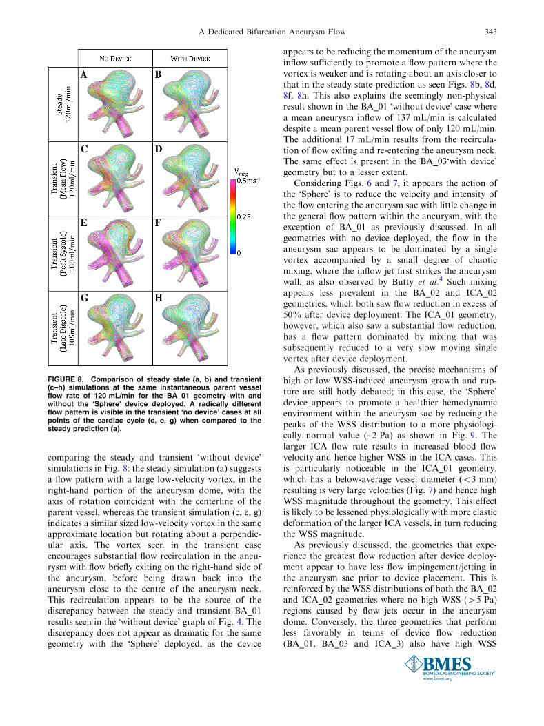
comparing the steady and transient ‘without device’simulations in Fig. 8: the steady simulation (a) suggestsa flow pattern with a large low-velocity vortex, in theright-hand portion of the aneurysm dome, with theaxis of rotation coincident with the centerline of theparent vessel, whereas the transient simulation (c, e, g)indicates a similar sized low-velocity vortex in the sameapproximate location but rotating about a perpendic-ular axis. The vortex seen in the transient caseencourages substantial flow recirculation in the aneu-rysm with flow briefly exiting on the right-hand side ofthe aneurysm, before being drawn back into theaneurysm close to the centre of the aneurysm neck.This recirculation appears to be the source of thediscrepancy between the steady and transient BA_01results seen in the ‘without device’ graph of Fig. 4. Thediscrepancy does not appear as dramatic for the samegeometry with the ‘Sphere’ deployed, as the device
appears to be reducing the momentum of the aneurysminflow sufficiently to promote a flow pattern where thevortex is weaker and is rotating about an axis closer tothat in the steady state prediction as seen Figs. 8b, 8d,8f, 8h. This also explains the seemingly non-physicalresult shown in the BA_01 ‘without device’ case wherea mean aneurysm inflow of 137 mL/min is calculateddespite a mean parent vessel flow of only 120 mL/min.The additional 17 mL/min results from the recircula-tion of flow exiting and re-entering the aneurysm neck.The same effect is present in the BA_03‘with device’geometry but to a lesser extent.
Considering Figs. 6 and 7, it appears the action ofthe ‘Sphere’ is to reduce the velocity and intensity ofthe flow entering the aneurysm sac with little change inthe general flow pattern within the aneurysm, with theexception of BA_01 as previously discussed. In allgeometries with no device deployed, the flow in theaneurysm sac appears to be dominated by a singlevortex accompanied by a small degree of chaoticmixing, where the inflow jet first strikes the aneurysmwall, as also observed by Butty et al.4 Such mixingappears less prevalent in the BA_02 and ICA_02geometries, which both saw flow reduction in excess of50% after device deployment. The ICA_01 geometry,however, which also saw a substantial flow reduction,has a flow pattern dominated by mixing that wassubsequently reduced to a very slow moving singlevortex after device deployment.
As previously discussed, the precise mechanisms ofhigh or low WSS-induced aneurysm growth and rup-ture are still hotly debated; in this case, the ‘Sphere’device appears to promote a healthier hemodynamicenvironment within the aneurysm sac by reducing thepeaks of the WSS distribution to a more physiologi-cally normal value (~2 Pa) as shown in Fig. 9. Thelarger ICA flow rate results in increased blood flowvelocity and hence higher WSS in the ICA cases. Thisis particularly noticeable in the ICA_01 geometry,which has a below-average vessel diameter (<3 mm)resulting is very large velocities (Fig. 7) and hence highWSS magnitude throughout the geometry. This effectis likely to be lessened physiologically with more elasticdeformation of the larger ICA vessels, in turn reducingthe WSS magnitude.
As previously discussed, the geometries that expe-rience the greatest flow reduction after device deploy-ment appear to have less flow impingement/jetting inthe aneurysm sac prior to device placement. This isreinforced by the WSS distributions of both the BA_02and ICA_02 geometries where no high WSS (>5 Pa)regions caused by flow jets occur in the aneurysmdome. Conversely, the three geometries that performless favorably in terms of device flow reduction(BA_01, BA_03 and ICA_3) also have high WSS
FIGURE 8. Comparison of steady state (a, b) and transient(c–h) simulations at the same instantaneous parent vesselflow rate of 120 mL/min for the BA_01 geometry with andwithout the ‘Sphere’ device deployed. A radically differentflow pattern is visible in the transient ‘no device’ cases at allpoints of the cardiac cycle (c, e, g) when compared to thesteady prediction (a).
A Dedicated Bifurcation Aneurysm Flow 343

distributions with peaks from flow jets in the aneurysmsac before device placement. The ICA_01 case does notfit this pattern of high WSS in the aneurysm sac cor-responding to poor flow reduction by the device, butthe smaller size of the ICA_01 aneurysm (with a heightand width roughly equal to the parent vessel diameter)results in less flow jetting generally and a flow patternin the aneurysm that is more similar to the BA_02 andICA_02 geometries. It is also apparent that higheraneurysm inflow, either with or without the device(detailed in Fig. 5), does not appear to correlate withincreased WSS magnitude in the aneurysm sac.
The authors also created plots of pressure for eachvessel before and after device deployment, which are notincluded here as no salient changes were seen, with theexception of a small increase in inlet pressure after devicedeployment, corresponding to the increased resistance toflow in the vessel. The large increases in aneurysm sacpressure correlated with aneurysm rupture, which wereobserved by Cebral et al.6 following FD deployment,would not be detected in this study, as the pressure in-crease was attributed to the reversal of parent vesselstenosis, which cannot be modeled when assuming arigid vessel wall as in the case of the current study.
FIGURE 9. Transient simulation WSS magnitude distributions for each geometry with and without the ‘Sphere’ deployed, viewedfrom both the front and the back. Results are shown at maximum inflow (peak systole) and although the magnitude of the WSSvaries throughout the cardiac cycle, the distribution changes very little from that seen in the figure.
PEACH et al.344
The correlation between a number of geometricfeatures of each aneurysm and the aneurysm inflowcalculated before and after device placement wasinvestigated. No correlation was found with parent ordaughter vessel size or with the proportion of outflowleaving each daughter vessel. These factors were alsoconsidered for the flow reduction achieved by thedevice with no correlation found. No correlation wasfound between the ‘no device’ aneurysm inflow and thesubsequent effectiveness of the deployed device. Theasymmetric distribution of outflow between daughtervessels across the geometries was found to have nocorrelation with device effectiveness. The ‘peakedness’(defined as the ratio of maximum inlet velocity to meaninlet velocity and similar to the kurtosis in this case) ofthe flow profile entering the aneurysm was also foundto have no correlation with the flow reduction due tothe device.
In the authors’ experience, the flow reductions fromthe ‘Sphere’ device deployed in bifurcation aneurysmsare comparable to those produced by conventionallow-porosity stents such as the SILK/PED, for side-wall and bifurcation aneurysms. It is intended that thefull details of such a comparative study will be thebasis of a future publication and are not included herefor brevity. Although such flow reductions are com-parable, bifurcation aneurysms present significantlymore clinical difficulties than sidewall cases, and thetreatment of bifurcation aneurysms with conventionalFDs is often seen as a treatment of last resort.21 Thepossibility of using the ‘Sphere’ device to treat suchdifficult aneurysms, and especially difficult cases thatare also wide-necked such as the BA_01 geometry,without the placement of the device within the delicateaneurysm sac is also highly desirable.
The current study has shown the ‘Sphere’ device tohave a good flow-diverting ability in a number ofbifurcation aneurysm geometries. However, significantaspects of the device’s design have not been analyzed:chiefly the device’s manufacture, deliverability, and themechanical deformations experienced by both deviceand vessel wall that govern device security. Of theseelements the question of device security and theprevention unintended migration is of paramountimportance; the authors are currently confronting thisdesign issue and intend to publish further analysis infuture publications.
CONCLUSIONS
Preliminary CFD analysis in a number of aneurysmlocations and geometries indicates that the ‘Sphere’design in this study is a viable flow-diverter designfor treating bifurcation aneurysms by introducing
substantial aneurysm inflow decrease. A range of flowreductions, which are comparable to those achievedwith commercially available devices, is seen across thesix aneurysms simulated. In all six geometries the de-vice is found to reduce the WSS distribution within theaneurysm sac to values closer to a healthy vessel. Theeffectiveness of the ‘Sphere’ device is compared to anumber of geometric and flow-based features of eachaneurysm geometry, where no correlations have beenobserved.
ACKNOWLEDGMENTS
TP and YV are engaged as scientific/technical con-sultants by the Minimally Invasive New TechnologiesProgram, Weill-Cornell Medical College and NewYork Presbyterian Hospital, New York USA. Allauthors acknowledge the support of the Leona M andHarry B Helmsley Charitable Trust, New York, NY,USA in funding this study. The device discussed in thispaper is covered by three US patents [US8663301-B2(issued), US 12/332,727(allowed, not yet issued),and US13/648,177(in examination)]. This work doesnot involve human subjects, vertebrate animals,human embryonic stem cells and cells or tissuesobtained by means other than commercial sale.
OPEN ACCESS
This article is distributed under the terms of theCreative Commons Attribution License which permitsany use, distribution, and reproduction in any med-ium, provided the original author(s) and the source arecredited.
REFERENCES
1Alfano, J., J. Kolgega, S. K. Natarajan, J. Xiang, R.Paluch, E. Levy, A. H. Siddiqui, and H. Meng. Intracranialaneurysms occur more frequently at bifurcation sites thattypically experience higher hemodynamic stresses. Neuro-surgery 2013. doi:10.1227/NEU.0000000000000016.2Appanaboyina, S., F. Mut, C. M. Putman, R. Lohner, andJ. R. Cebral. Computational fluid dynamics of stentedintracranial aneurysms using adaptive embedded unstruc-tured grids. Int. J. Numer. Methods Fluids 57:475–493,2008.3Baek, H., M. V. Jayaraman, P. D. Richardson, and G. E.Karniadakis. Flow instability and wall shear stress varia-tion in intracranial aneurysms. J. R. Soc. Interface 7:967–988, 2010.4Butty, V. D., K. Gudjonsson, P. Buchel, V. B. Makhijani,Y. Ventikos, and D. Poulikakos. Residence times and
A Dedicated Bifurcation Aneurysm Flow 345

basins of attraction for a realistic right internal carotidartery with two aneurysms. Biorheology 39:387–393, 2002.5Byrne, J. V, and I. Szikora. Flow diverters in the man-agement of intracranial aneurysms: a review. EJMINT,2012.6Cebral, J. R., F. Mut, M. Raschi, E. Scrivano, R. Ceratto,P. Lylyk, and C. M. Putman. Aneurysm rupture followingtreatment with flow-diverting stents: computational hemo-dynamics analysis of treatment. AJNR 32:27–33, 2011.7Chen, H., A. Selimovic, H. Thompson, A. Chiarini, J.Penrose, Y. Ventikos, and P. N. Watton. Investigating theinfluence of haemodynamic stimuli on intracranial aneu-rysm inception. Ann. Biomed. Eng. 41:1492–1504, 2013.8Connolly, E. S., A. A. Rabinstein, J. R. Carhuapoma, C. P.Derdeyn, J. Dion, J. Dion, R. T. Higashida, B. L. Hoh, C.J. Kirkness, C. J. Kirkness, A. M. Naidech, C. S. Ogilvy,A. B. Patel, B. G. Thompson, and P. Vespa. Guidelines forthe management of aneurysmal subarachnoid hemorrhage:a guideline for healthcare professionals from the AmericanHeart Association/American Stroke Association. Stroke43:1711–1737, 2012.9D’Urso, P. I., G. Lanzino, H. J. Cloft, and D. F. Kallmes.Flow diversion for intracranial aneurysms: a review. Stroke42:2363–2368, 2011.
10Dempere-Marco, L., E. Oubel, M. Castro, C. Putman, A.Frangi, and J. Cebral. CFD analysis incorporating theinfluence of wall motion: application to intracranial aneu-rysms. MICCAI 438–45:2006, 2006.
11Fu, W., Z. Gu, X. Meng, B. Chu, and A. Qiao. Numericalsimulation of hemodynamics in stented internal carotidaneurysm based on patient-specific model. J. Biomech.43:1337–1342, 2010.
12Griffith, T. M. Modulation of blood flow and tissue per-fusion by endothelium-derived relaxing factor. Exp. Phys-iol. 79:873–913, 1994.
13Hale, B. Y. J. F., D. A. Mcdonald, and J. R. Womersley.Velocity profiles of oscillating arterial flow, with somecalculations of viscous drag and the reynolds number.Physiology 128:629–640, 1955.
14Hennerici, M., W. Rautenberg, G. Sitzer, and A. Schwartz.Transcranial Doppler ultrasound for the assessment ofintracranial arterial flow velocity—part 1. Surg. Neurol.27:439–448, 1987.
15Higashida, R., W. Smith, D. Gress, R. Urwin, C. Dowd, P.Balousek, and V. Halbach. Intravascular stent and endo-vascular coil placement for a ruptured fusiform aneurysmof the basilar artery. Neurosurgery 87:944–949, 1997.
16Janiga, G., C. Rossl, M. Skalej, and D. Thevenin. Realisticvirtual intracranial stenting and computational fluiddynamics for treatment analysis. Biomechanics 46:7–12,2013.
17Jou, L.-D., and M. E. Mawad. Hemodynamic effect ofneuroform stent on intimal hyperplasia and thrombusformation in a carotid aneurysm. Med. Eng. Phys. 33:573–580, 2011.
18Kamenskiy, A. V., Y. A. Dzenis, J. N. Mactaggart, A. S.Desyatova, and I. I. Pipinos. In vivo three-dimensionalblood velocity profile shapes in the human common,internal, and external carotid arteries. Vasc. Surg. 54:1011–1020, 2011.
19Kim, M., D. Taulbee, M. Tremmel, and H. Meng. Com-parison of two stents in modifying cerebral aneurysmhemodynamics. Ann. Biomed. Eng. 36:726–741, 2009.
20Klisch, J., V. Sychra, C. Strasilla, T. Liebig, and D. Fio-rella. The woven endobridge cerebral aneurysm emboliza-
tion device (WEB II): initial clinical experience. Neuro-radiology 53:599–607, 2011.
21Kulcsar, Z., U. Ernemann, S. G. Wetzel, A. Bock, S.Goericke, V. Panagiotopoulos, M. Forsting, D. A. Ruefenacht,and I. Wanke. High-profile flow diverter (silk) implantation inthe basilar artery. Stroke 41:1690–1696, 2010.
22Lieber, B. B., V. Livescu, L. N. Hopkins, and A. K.Wakhloo. Particle image velocimetry assessment of stentdesign influence on intra-aneurysmal flow. Ann. Biomed.Eng. 30:768–777, 2002.
23Liou, T.-M., Y.-C. Li, and W.-C. Juan. Numerical andexperimental studies on pulsatile flow in aneurysms arisinglaterally from a curved parent vessel at various angles.Biomechanics 40:1268–1275, 2007.
24Lylyk, P., C. Miranda, R. Ceratto, A. Ferrario, E. Scri-vano, H. R. Luna, A. L. Berez, Q. Tran, P. K. Nelson, andD. Fiorella. Curative endovascular reconstruction of cere-bral aneurysms with the pipeline embolization device.Neurosurgery 64:632–643, 2009.
25Maimon, S., L. Gonen, E. Nossek, I. Strauss, R. Levite,and Z. Ram. Treatment of intra-cranial aneurysms with theSILK flow diverter: 2 years’ experience with 28 patients at asingle center. Acta Neurochir. (Wien) 154:979–987, 2012.
26Malek, A. M., S. L. Alper, and S. Izumo. Hemodynamicshear stress and its role in atherosclerosis. J. Am. Med.Assoc. 282:2035–2042, 1999.
27Nelson, P. K., P. Lylyk, I. Szikora, S. G. Wetzel, I. Wanke,and D. Fiorella. The pipeline embolization device for theintracranial treatment of aneurysms trial. AJNR 32:34–40,2011.
28Ni, M., and M. A. Abdou. A bridge between projectionmethods and simple type methods for incompressiblenavier—Stokes equations. IJNMBE 72:1490–1512, 2007.
29Perktold, K., M. Resch, and H. Florian. Pulsatile non-Newtonian flow characteristics in a three-dimensionalhuman carotid bifurcation model. Biomech. Eng. 113:464–475, 1991.
30Pierot, L. Flow diverter stents in the treatment of intra-cranial aneurysms: where are we? Neuroradiology 38:40–46,2011.
31Pierot, L., T. Liebig, V. Sychra, K. Kadziolka, F. Dorn, C.Strasilla, C. Kabbasch, and J. Klisch. Intrasaccular flow-disruption treatment of intracranial aneurysms: pre-liminary results of a multicenter clinical study. AJNR33:1232–1238, 2012.
32Pierot, L., J. Klisch, C. Cognard, I. Szikora, B. Mine, K.Kadziolka, V. Sychra, I. Gubucz, A.-C. Januel, and B.Lubicz. Endovascular WEB flow disruption in middlecerebral artery aneurysms: preliminary feasibility, clinical,and anatomical results in a multicenter study. Neurosurgery73:27–34, 2013; (discussion 34–5).
33Ponzini, R., C. Vergara, G. Rizzo, A. Veneziani, A. Roghi,A. Vanzulli, O. Parodi, and A. Redaelli. Womersley num-ber-based estimates of blood flow rate in doppler analysisin vivo validation by. IEEE Trans. Biomed. Eng. 57:1807–1815, 2010.
34Reymond, P., O. Vardoulis, and N. Stergiopulos. Genericand patient-specific models of the arterial tree. J. Clin.Monit. Comput. 26:375–382, 2012.
35Ringelstein, E., B. Kahlscheuer, E. Niggemeyer, and S.Otis. Transcranial doppler sonography: anatomical land-marks and normal velocity values. Ultrasound Med. Biol.16:745–761, 1990.
36Saatchi, I., K. Yavuz, C. Ozer, S. Geyik, and H. S. Cekirge.Treatment of intracranial aneurysms using the pipeline
PEACH et al.346
flow-diverter embolization device: a single-center experi-ence with long-term follow-up results. AJNR 33:1436–1446,2012.
37Sadasivan, C., B. B. Lieber, M. J. Gounis, D. K. Lopes,and L. N. Hopkins. Angiographic quantification of con-trast medium washout from cerebral aneurysms after stentplacement. AJNR. Am. J. Neuroradiol. 23:1214–1221, 2002.
38Sforza, D. M., C. M. Putman, and J. R. Cebral. Hemo-dynamics of cerebral aneurysms. Annu. Rev. Fluid Mech.41:91–107, 2009.
39Shobayashi, Y., S. Tateshima, R. Kakizaki, R. Sudo, K.Tanishita, and F. Vinuela. Intra-aneurysmal hemodynamicalterations by a self-expandable intracranial stent and flowdiversion stent. Neurointerventional Surg. 1–5, 2012. doi:10.1136/neurintsurg-2012-010488.
40Sotiropoulos, F., Y. Ventikos, and T. Lackey. Chaoticadvection in three-dimensional stationary vortex-break-down bubbles: Sil’nikov’s Chaos and the Devil’s Staircase.Fluid Mech. 444:257–297, 2001.
41Stuhne, G. R., and D. A. Steinman. Finite-element mod-eling of the hemodynamics of stented aneurysms. Biomech.Eng. 126:382–387, 2004.
42Trager, A., C. Sadasivan, J. Seong, and B. B. Lieber.Correlation between angiographic and particle image ve-locimetry quantification of flow diverters in an in vitromodel of elastase-induced rabbit aneurysms. Biomed. Eng.(NY) 131:1–8, 2009.
43Ujiie, H., Y. Tamano, K. Sasaki, and T. Hori. Is the aspectratio a reliable index for predicting the rupture of a saccularaneurysm? Neurosurgery 48:495–502, 2001.
44Valencia, A. A., A. M. Guzman, E. A. Finol, andC. H. Amon. Blood flow dynamics in saccular aneurysmmodels of the basilar artery. Biomech. Eng. 128:516–526,2006.
45Valen-Sendstad, K., K. A. Mardal, and D. A. Steinman.High-resolution computational fluid dynamics detects high-frequency velocity fluctuations in bifurcation, but notsidewall, aneurysms of the middle cerebral artery. J. Bio-mech. 46:402–407, 2012.
46Van Doormaal, J. P., and G. D. Raithby. Enhancements ofthe simple method for predicting incompressible fluid flows.Numer. Heat Transf. 7:147–163, 1984.
47Vernooij, M. W., M. A. Ikram, H. L. Tanghe, A. J. P. E.Vincent, A. Hofman, G. P. Krestin, W. J. Niessen, M. M.B. Breteler, and A. van der Lugt. Incidental findings onbrain mri in the general population. N. Engl. J. Med.357:1821–1828, 2007.
48Webster, R. An algebraic multigrid solver for Navier–Stokes problems. Int. J. Numer. Methods Fluids 18:761–780, 1994.
49Wiebers, D. O., J. P. Whisnant, J. Huston, I. Meissner,R. D. Brown, D. G. Piepgras, G. S. Forbes, K. Thielen,D. Nichols, W. M. O’Fallon, J. Peacock, L. Jaeger, N. F.Kassell, G. L. Kongable-Beckman, and J. C. Torner.Unruptured intracranial aneurysms: natural history, clini-cal outcome, and risks of surgical and endovascular treat-ment. Lancet 362:103–110, 2003.
50Womersley, J. R. Method for the calculation of velocity,rate of flow and viscous drag in arteries when the pressuregradient is known. J. Physiol. 127:553–563, 1955.
A Dedicated Bifurcation Aneurysm Flow 347