
The Specification for Reinstatements of Openings in the ... SROH presentation with trainer... · 1...
44
1 The Specification for Reinstatements of Openings in the Highway - 3 rd edition changes. Including a reminder of the basics.
Transcript of The Specification for Reinstatements of Openings in the ... SROH presentation with trainer... · 1...

1
The Specification for Reinstatements of Openings in the Highway -3rd edition changes. Including a reminder of the basics.

2
A Presentation by Enterprise2
Housekeeping
Welcome and Admin
Trainer Notes:
•Inform Operatives where the welfare facilities are located
•Inform Operatives where the nearest fire escape is, and who the nearest
first aider is
•Ask Operatives to turn their mobile phones on silent throughout the duration of the course
•Reminder that Smoking is only allowed in designated areas

3
A Presentation by Enterprise3
Specification for Reinstatement of Openings in the Highway
Issued in April 2010 and operational on 1 October 2010

4
A Presentation by Enterprise4
Title here – white text, Arial font 28pt
Most Significant changes in SROH edition 3
• Update of Asphalt Terminology in line with EN standards.
• Easier to follow. More use of diagrams, photos and a flow chart to
make choices of permitted reinstatement options more clear.
• Asphalt Compaction, minor changes.
• Minor design (layer thickness changes) in line with National Standards.
• Clearer diagrams for fixed features and fillets around ironwork.
• Amended rules on trim back to fixed features, edge preparation and
sealing.
• Inclusion of very high amenity areas with tighter intervention criteria
• Wide ranging changes to App A9 – use of Alternative materials to,
hopefully, improve take up.
•App A10 PCSM’s. Reworded and moved to App A2.
• Reinstatement methods A to E rationalised
The document is a fairly significant update but is not a complete re-write; it follows the familiar format of editions 1 & 2 while hopefully addressing many of
the comments and requests received from consultees.

5
A Presentation by Enterprise5
Material Descriptions -- All mixtures are now Asphalt
Either Asphalt Concrete, HRA or SMA
Old Description New Description
0/20 Dense Macadam Binder Course 125pen AC 20 Dense Bin 100/150
0/10 Close Graded Surface Course AC 10 Close Surf 100/150
35% 0/14 HRA Surface Course 50 pen 65 psv HRA 35/14F Surf 40/60 65psv
14mm SMA Surface Course 50pen 65 psv SMA 14 Surf 40/60 65psv
Update of Asphalt Terminology in line with EN standards
Details of updated EN standard terminology for asphalt mixtures, previously covered in an Advice Note, now included in the document.
Anything containing bitumen or tar is now called asphalt and there is potential for
confusion as historically, in the UK, asphalt meant hot rolled asphalt.
HRA is still HRA SMA is still SMA but the old UK term of Macadam is now
replaced with Asphalt Concrete. The mixtures are the same, they are name
changes only. Previously the aggregate size was specified as a particle size range, for blacktop, usually 0/20 etc meaning 0 i.e dust to maximum 20mm; EN
asphalt standards just use the single maximum particle size as a reference.
Binder Course is abbreviated to Bin and Surface Course to Surf. Binder grades
are now to be referred to by the penetration range rather than the specification
mid point eg 40/60 rather than 50pen. Where polished stone value of surface course aggregate is specified then it is usual for this to form part of the material
description and appear on delivery tickets but this is not a mandatory
requirement.

6
A Presentation by Enterprise6
Flow chart to aid flexible reinstatement options
• More diagrams, flow charts and, for the first time, photographs used in an attempt to make things easier to follow.
Figure SO1 shows a flowchart that leads through the process for blacktop
selection

7
A Presentation by Enterprise7
Flow chart to aid flexible reinstatement options - contd
• Check NSG for any site specific info or construction issues
• Confirm Road category
• Identify binder course/surface course options from App A3.0 – A3.4
• Make selection and refer to A2 for mixture details.
• Check in S6.4 that exceptions don’t rule out the selected surface course – if they do then make another, appropriate, selection.

8
A Presentation by Enterprise8
Edition 2 ambiguities and errors.
• Edge depression – a trip may be at interface with existing c/way or against included ironwork.
• Overbanding shall be HAPAS – so far there is only one.• Compacted asphalt layer thickness table showed materials
that weren’t permitted.• Much misunderstanding over what surface course material
was allowed/expected where. Cleared up, hopefully, by new flow chart
• Some A3 Flexible Road sections indicated layer thickness for other than the default binder grade – now rationalised in App A11.
• App A10 PCSM’s incorrectly stated that PCSM’s may be used in substitution for any permitted bituminous material; this has been reworded and moved to A2. A10 not used now.
• Other typo’s and minor errors to numerous to mention.
In a nutshell the asphalt choices are:
Surface Courses-Existing HRA and chippings must be replaced with the same,
wherever it occurs at the surface and it must still be used in 0,1 and 2 roads even if the existing has been covered with a surface treatment. Mixtures are
30/14 or 35/14 type F unless agreed otherwise. They must be design mixes in 0
and 1 roads. In 2, 3 and 4 roads designs are preferred but recipe mixes may be
used.
HRA and chips may be used in any road other than existing SMA or thin
surfacing.
SMA of nominal size to match the existing must be used wherever the existing is
SMA and must also be used in existing thin surfacing unless the Authority asks
for the thin surfacing to be replaced like for like.
SMA may be used in any road other than existing HRA.
Close Graded Surface Course may be used in existing similar material or surface
treated 3 and 4 roads.
Binder Courses-HRA Bin, SMA Bin or AC Bin may be used in any road category
or type of existing flexible construction but be careful to increase the thickness if
HRA Bin is used, refer to App A11.
The use of the materials hasn’t really changed but by using the flowchart it should
be easier to come to the correct conclusions; at least you’re told where to look.
PCSM’s must have a current HAPAS certificate and will have been approved on
the basis of equivalence to one of the hot lay options. They may be used as
interim material anywhere and as permanent material wherever the equivalent hot lay mixture is
permitted in footways or type 3 or 4 roads.

9
A Presentation by Enterprise9
Asphalt thickness requirements
• Design Manual for Road and Bridge Works
� HD 26 thickness requirements fully reflected in Type 0 and 1 roads
• Types 2, 3 and 4 Roads
� Additional thickness, up to HD 26 requirements, may be called up via A3 Notes, by the Authority where they are doing the same (Type 2 = 320mm, Type 3 = 250mm and Type 4 = 200mm, assuming use of preferred binder grade)
• Asphalt design thickness now reflects the ‘preferred’ binder grades and also requires different thickness for HRA Bin as per HD26. HD26 design thickness for
road types 2, 3 and 4 still not reflected in the specification but where the Authority
has used HD 26 on a particular road they may inform the Undertaker and require
them to do the same.

10
A Presentation by Enterprise10
Amended rules on trim back
• Slight changes to trim back rules to fixed features. In f/ways the feature needs to have a diameter or edge, adjacent to the reinstatement, greater than 250mm
before the surface needs to be trimmed to the feature. This avoids the need to
trim back to lighting columns, sign posts etc.

11
A Presentation by Enterprise11
Trim back

12
A Presentation by Enterprise12
Stepped edge detail, 0 and 1 roads only
trench
In types 0 and 1 roads where the Authority uses a stepped edge detail they may notify and require the Utility to follow the same detail. It is limited to a maximum
step of 75mm and small reinstatements and narrow transverse trenches are
excluded.

13
A Presentation by Enterprise13
Reinstatement around features – good practice examples
Photos have been used to illustrate good practice eg the extent to which it is expected that modules be cut to fill in around fixed features. The photos are only
in Notes for Guidance, so not a mandatory part of the code but hopefully they will
reduce the amount of disputes.

14
A Presentation by Enterprise14
Reinstatement around features – good practice examples

15
A Presentation by Enterprise15
Reinstatement around features – good practice examples
Imaginative local loss of pattern may be preferable to using small cut pieces or having a mortar infill.

16
A Presentation by Enterprise16
Very High Amenity Areas? (S1.4.4)
• ‘Where an Authority is able to demonstrate that a high
amenity or high duty footway has been constructed and maintained to a standard in excess of that prescribed in sections S2.2 and S2.3 and registered accordingly then in these circumstances the reinstatement shall meet the Authority’s standard of maintenance and their declared intervention criteria’.

17
A Presentation by Enterprise17
Asphalt compaction requirements
• S10.2.3 – Bituminous Materials – Air Void Limits
� No. of Passes removed to Notes for Guidance
� 3 minor changes to Table 10.1 (Carriageways only):
− AC 10 Close SC – increased to 11% (from 10%)
− HRA SC – decreased to 7% (from 8%)
− HRA BC – decreased to 9% (from 10%)
• S10.2.3 – Bituminous Materials – Coring Locations
� Anywhere in reinstatement
� No closer than 100mm from SU Apparatus for void testing.
• Asphalt compaction (air voids) test methods referred to more specifically. Now specific test methods rather than a BS standard reference which allowed various
methods and ‘interpretation’. This should cut down on disputes. Small increase in
void content for AC 10 Surf and decrease for HRA.
• EN 12697 – 5, procedure A, in water - for maximum density measurement.
• EN 12697 – 6, for bulk density measurement (the reference to part 5 for bulk density is a typo) choice of methods for routine testing but for reference purposes
or disputes procedure C, sealed specimen must be used.
• Notes for guidance on void testing have been added.

18
A Presentation by Enterprise18
Appendix A9. Alternative Reinstatement Materials
• Aimed to improve take up of Alternative Materials
• Materials complying with SHW 800 series may be used ‘as of right’ without trial.
• Other Alternative Materials need A9 trials – but only once! A Highway Authority must give engineering reasons not to accept evidence from a previous trial and allow similar materials to be used.
• Need for Quality Control System amplified
Alternative Reinstatement Materials (ARM’s) may be either:
SMR - Structural Material for Reinstatements : Foamed Concrete or Hydraulically
Bound in accordance with the SHW and allowed ‘as of right’ or other proprietary
materials that may only be used with the agreement of the Highway Authority,
need an App A9 trial and are judged against the same parameters as foamed concrete and used in the same circumstances.
or
SMF - Stabilised Material for Fill is classified as one of the classes A to D of fill
material and used appropriately. SMF is also likely to need an A9 trial.
The need for well documented QA procedures encourages off site processes
rather than mixing at the side of the road and off site production also makes it
more likely that the materials can be manufactured to comply with the SHW and
so not need a trial or HA permission.

19
A Presentation by Enterprise19
Appendix A10. PCSM’s
• Re - worded and moved to A2 – A10 not now used.
• Materials are now to be approved as equivalent to a Hot Lay type and used as appropriate.
• Due to concerns over soft and unstable PCSM’s
they must be capable of wet flush core sampling, to allow void testing, at 6 months from the date of permanent reinstatement. (A8.3)
Changes are to address perceived ambiguities and concerns over the use of PCSM’s.
The statement in A10 that ‘Approved PCSMs, laid and compacted to App A8,
may be used in substitution for any permitted bituminous material, at the discretion of the Undertaker’, was misleading, it was never intended that PCSM
be used in-lieu of HRA or SMA but only in place of what they were considered
equivalent to.
Originally approval for cold –lay products, in practical terms, was only given to
macadam style products but more recently cold-lay SMA has been developed.
On occasion materials were so soft that cores could not be obtained even after
2yrs in the ground so how could these materials be ‘equivalent to hot-lay’?
It’s now clear that products will be approved as equivalent to one of the hot-lay
options and may be used wherever that hot-lay equivalent is permitted.

20
A Presentation by Enterprise20
Ambiguities in 2nd edition – as laid profile / edge depression
Surprisingly this detail caused widespread misinterpretation in the past.
An edge depression or trip may be at the interface between a reinstatement and
the existing surface or between the reinstatement and an included fixed feature.
If there is no edge depression against an included feature then the ironwork etc
is subject to the same crown/depression intervention limits as any other
reinstatement.
The immediately adjacent surface to a fixed feature is the reinstatement not the
existing road.

21
A Presentation by Enterprise21
Ambiguities in 2nd edition – Asphalt layer thickness
Note 4 on types 2, 3 and 4 flexible construction allows the HA to require full HD26 construction.
On Figs A3.0 to A3.4 the nominal 60mm binder course line is where the base
layer starts.
In Highway construction there would be sub base, base, binder course and
surface course materials but in the SROH the base material may either be additional binder course, FCR or SMR or, in types 3 and 4 only, additional sub
base. This has never changed since SROH 1st edition and there is still
misunderstanding!

22
A Presentation by Enterprise22
Reinstatement methods, A to E rationalised
Table A2.6 Key to Reinstatement Methods
Flexible & Composite Roads
Section S6
Rigid & Modular Roads
Section S7
Footways, Footpaths & Cycle Tracks
Section S8
Modular
Reinstatement Method
(At First visit)
Flexible
(Appendix A3.0-A3.4 incl.)
Composite
(Appendix A4.0-A4.3 incl.)
Rigid
(Appendix A5.0-A5.2 incl.)
Bituminous Base (Roadbase)
(Appendix A6.1)
Composite Base (Roadbase)
(Appendix A6.2)
Granular Base (Roadbase)
(Appendix A6.3)
Flexible
(Appendix A7.1)
Rigid
(Appendix A7.2)
Modular
(Appendix A7.3)
All Permanent
Method A
(Types 0-4 incl.)
Method A
(Types 0-4 incl.)
Method A
(Types 0-4 incl.)
Method A
(Types 3, 4 only)
Method A
(Types 3, 4 only)
Method A
(Types 3, 4 only)
Method A
Method A
Method A
Interim with Permanent
Binder Course
Method B
(Types 0-4 incl.)
Method B
(Types 0-4 incl.)
N/A
N/A
N/A
N/A
Method B
N/A
N/A
Interim with Permanent Base
(Roadbase)
Method C
(Types 3, 4 only)
Method C
(Types 0-4 incl.)
N/A
N/A
N/A
N/A
N/A
N/A
N/A
Interim with Permanent Sub-
base
Method D
(Types 0-4 incl.)
Method D
(Types 0-4 incl.)
Method D
(Types 0-4 incl.)
Method D
(Types 3, 4 only)
Method D
(Types 3, 4 only)
Method D
(Types 3, 4 only)
Method D
Method D
Method D
Permanent incorporating
Interim Surface Overlay
N/A
N/A
Method E
(Types 0-4 incl.)
N/A
N/A
N/A
N/A
N/A
N/A
Reinstatement methods A to E are now the same regardless of the type of reinstatement.
Method A – All permanent
Method B – Interim surface, permanent binder course
Method C – Interim surface and binder courses, permanent base
Method D – Interim surface, binder course and base with permanent sub base
Method E – Interim asphalt overlay on permanent rigid construction.
Obviously some methods can’t be applied to some types of construction so they
are listed as N/A

23
A Presentation by Enterprise23
Ambiguities in 2nd edition – Material choice flow chart
Type 2, 3 and 4 Roads - ACSC is a permissible Surface Course
option in existing roads surfaced with Coated Mixtures to BS 4987.
For Type 3 and 4 Roads where an existing HRA Surface Course
has been overlaid, ACSC is a permissible Surface Course option.
S6.4.1(1),
S6.4.1(2) and
S6.4.3
ALLRoads - if existing Surface Course is SMA, then reinstated
Surface Course MUST be SMA.
Appendix A2.2.2(2)(a)
Type 2 Roads - if existing Surface Course is HRA (including where
the running surface has a surface dressing or any other surface
treatment), then reinstated Surface Course MUST be HRA.
Type 3 and 4 Roads - if existing Surface Course is HRA (but the
running surface has NOT been overlaid with a surface dressing or
any other surface treatment ), then the reinstated Surface Course
MUST be HRA.
Type 2, 3 and 4 Roads - if existing Surface Course is an Asphalt
Concrete, then reinstated Surface Course MAY be HRA.
Preferred
Preferred
(Alternative)
Figure A2.4 Permanent Reinstatement Options for Hot Lay Flexible Materials (Road Types 2, 3 and 4)
S6.3.3
S6.4.3 and
S6.4.1(2)
Appendix A2.2.1(2)(b)
S6.4.2(1) and
S6.4.2.1(a) to (c)
incl.
Appendix A2.1.2(2)(a)
Appendix A2.2.1(2)(c)
Type 2 Roads - Base Equivalence is NOT a Permitted Option.
Type 3 and 4 Roads - Base Equivalence IS a Permitted Option
Appendix A2.2.2(2)(a)
Appendix A2.1.1(2)(b)
Appendix A2.3.2(2)
Appendix A2.3.1(1)
Appendix A2.1.2(2)(b)
Appendix A2.2.1(2)(a)
Appendix A2.1.2(2)
Appendix A2.2.2(2)(b)
Appendix A2.2.1
Appendix A2.1.1(2)(c)
SMA 20 bin 70/100 WTR 1
AC 10 close surf 100/150
SMA 20 bin 40/60 WTR 1
Openings over 500mm width - HRA 60/20 F
bin 40/60
SMASCAppendix
A2.2.1
40mm for 14mm SMA
30mm for 10mm SMA
[S6.4.2(1)(a) and
HRABC
Type 2 - 245mm (60+185)
Type 3 - 150mm (60+90)
Type 4 - 110mm (60+50)
ACSC
Permissible
Type 2 - 245mm (60+185)
Type 3 - 150mm (60+90)
Type 4 - 110mm (60+50)
Appendix
A2.2.2
SMA 14 surf PMB or 40/60 or 70/100
WTR 1 or 2
SMA 6 surf PMB or 40/60 or 70/100
WTR 1 or 2
HAPAS certificated Thin Surface Course
Systems such as TSCS 14 or TSCS 10
Preferred
(No Options)
Permissible
SMA 10 surf PMB or 40/60 or 70/100
WTR 1 or 2
Permissible
Restrictions at Surface Course Mixture Options
Confirm Road Category and
Select Permissible
Reinstatement Appendix
Types 2, 3
and 4
Type 2 - Appendix A3.2
Type 3 - Appendix A3.3
Type 4 - Appendix A3.4
Surface Course Preferred HRA 35/14 F surf 40/60 des WTR 1HRASC 40mm
HRA 30/14 F surf 40/60 des WTR 1
HRA 30/14 C surf 40/60 des WTR 1
Appendix A2.1.1(2)
Existing
Carriageway
Construction
Identify ALLOWABLE Bound Course Options and relevant Specification
under Appendices A2 and A3
Permissible
Permissible HRA 30/14 F surf 40/60 rec WTR 1 Appendix A2.1.1(2)(a)
Appendix
A2.1.1
ACBC
HRA 50/20 F bin 40/60
PermissibleOpenings up to 500mm width - HRA 50/14 F
bin 40/60
Appendix
A2.3.2
Preferred
(No Options)AC 20 dense bin 100/150
Preferred
(No Options)
Type 2 - 245mm (60+185)
Type 3 - 150mm (60+90)
Type 4 - 110mm (60+50)
SMABC
PermissibleOpenings up to 500mm width - SMA 14 bin
40/60 WTR 1 or SMA 14 bin 70/100 WTR 1
Flexible
Appendix
A2.1.2 Binder Course
[incl. Base Course]
(Types 2, 3 and 4)
Permissible
Permissible
(Alternative)
Permissible
40mmAppendix
A2.3.1
Material choice flow chart for flexible roads should remove some of the problems experienced in deciding what material is permitted/required where.
Start by identifying the road type 0 to 4 and the existing surface type; HRA, SMA,
or CGSC.
The relevant SROH appendix is then identified together with layer thickness, the
preferred and permitted material options, specific material descriptions for ordering and SROH references.
Remember that

24
A Presentation by Enterprise24
Material choices
The materials on the right hand side of the A3 figures are all choices unless there is a restriction to the circumstance of use detailed in S6.

25
A Presentation by Enterprise25
Reminder of the ‘Essentials’
• Compaction
� Method
� End product
• Bitumen Grades, Penetration etc
• Edge Preparation and Tack Coat
• Skid Resistance
� Texture depth
� PSV

26
A Presentation by Enterprise26
Method Compaction
• Confirm that the material complies with specification requirements - Backfill Class, Type 1 Sub Base, Maximum permitted particle size, moisture content etc.
• Choose combination of compaction equipment and layer thickness from table A8.1
• Carry out the correct number of passes shown in the table.
• If these things happen then the work must be deemed to comply.
All backfill and sub base used in reinstatement work should be compacted using the ‘Method’ approach. It’s essential that suitable compaction methods are adopted. Poor compaction of backfill and sub base is the most common cause of surface depression in the completed reinstatement.
Adequate compaction of each layer will more readily allow compaction of the
layer immediately above by providing a good “reaction” to the “action” of the
compaction plant. Once a poorly compacted layer is in place it is difficult if not
impossible to achieve good compaction in the layers above. This is a key point, contractors often do not appreciate that poor compaction of the backfill or sub
base may be the reason for high % air voids in the lower part of the blacktop.

27
A Presentation by Enterprise27
Method Compaction
Over 1800 kg/sq.m
1400-1800 g/sq.m
Over 2000 kg/m
1000-2000 kg/m
600-1000 kg/m
over 3500 kg/m
2000-3500 kg/m
1000-2000 kg/m
7 53NP63
All Above Plant : For Maximum and Minimum compacted layer thickness. See Appendix A2.6, Table A2.2
Alternative Compaction Plant for Areas of Restricted Access. (including small excavations and trenches less than 200 mm
width) Vibrotamper; 25 kg minimum. Percussive Rammer;10 kg minimum. Minimum of 6 compaction passes and Maximum of
100 mm compacted layer thickness
Notes for Table A8.1: 1)NP = Not Permitted 2)# = Not permitted on wholly cohesive material i.e. clay and/or silt with no
particles > 75 micron 3)Single drum vibrating rollers are vibrating rollers providing vibration on only one drum. 4)Twin drum vibrating rollers are vibrating rollers providing vibration on two separate drums
NP
4
NP
NP
6
7
NP
NP
200mm
NP
3
6
NP
4
5
NP
8
150mm
NP
5#
NP
NP
6#
NP
NP
NP
200mm
NP
3
8
NP
4
6
NP
8#
150mm
5NPVibrating Plate
22
34
6NPTwin drum vibrating roller
33
33
68Single drum vibrating roller
44Vibrating tamper - minimum 50kg
100mm100mm
Min. passes for compacted layer up to
Min. passes for compacted layer up to
Granular material
(20% or more granular including cement bound)
Cohesive material
(less than 20% granular)
Table 8.1
Plant and mass category
Under a method compaction approach there is no specification for Clegg Impact Value, CBR or any other performance measure; if the work isn’t observed then it
can’t be judged retrospectively by the Authority. Any Clegg Impact target or other
measure is a matter between the Utility and Contractor but it is sensible to carry
out checks limit future liability.

28
A Presentation by Enterprise28
Method Compaction
The minimum mass for vibrating plate compactors is 1400kg/m2 and although these machines are available they’re hardly ever seen; if smaller mass plates are
used then the method hasn’t been followed.

29
A Presentation by Enterprise29
End Product Compaction
213210PCSM Materials
NPNP26SMA Binder Course
21229HRA Binder Course
212210AC Binder Course
21028SMA Surface Course
21027HRA Surface Course
NPNP211AC 10 Close surface Course
213NPNPAC 6 Dense Surface Course
Min %Max %Min %Max %
FootwaysCarriageways
Permitted Air Voids
Bituminous Materials
The alternative approach to method compaction is compaction to produce an end product. In HAUC works this is the requirement for all asphalt layers to be compacted to below
certain maximum air void contents. The Asphalt equivalent to table A8.1 is table A NG
A8.3. Although this table gives guidance on compaction there is no guarantee that
following the procedure will produce the desired low void contents; it’s up to the contractor
to carry out whatever process is needed to comply with the end product requirement.
The key factors in achieving good asphalt compaction are:
Temperature – of the mixture, ambient temperature, wind chill and temperature of the
surface being covered. Cold surface, low mix temp. strong wind, thin lift = no chance!
Lift thickness – everything else being equal thinner lifts cool more quickly and are likely to
cause problems. A lift has to be thicker than allowed before this contributes towards poor
compaction.
Incorrect surcharge – material needs to achieve full compaction as the level approaches
that of the adjacent surface, once the compaction equipment is supported by the existing
mat it doesn’t do much.
Type of asphalt – if everything else is as it should be, temps etc, then HRA will always
compact to compliant void levels more easily than other materials, next SMA and then AC.
Compaction plant – although this is obviously important it is possible to achieve good compaction with most plant so long as attention is paid to the other elements.
30
A Presentation by Enterprise30
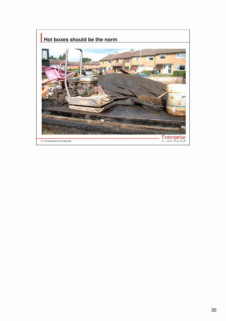
Hot boxes should be the norm

31
A Presentation by Enterprise31
Always use appropriate surcharge

32
A Presentation by Enterprise32
Edge problems
It’s important that the full surface course layer thickness exists at the edge and that enough surcharge is applied. Full thickness and adequately edge sealed and
tack coated work gives the best chance of keeping the weather out.

33
A Presentation by Enterprise33
Badly oxidised surface due to high void content
When bitumen is exposed to atmospheric oxygen in asphalt layers it oxidises and becomes brittle. If material is well compacted and has a low degree of permeability oxidation only occurs on the surface of the surface course, the rate of degradation is slow and the potential life of the material is achieved. If poor compaction allows oxygen throughout the layer, via interconnected voids, then degradation and early failure is inevitable. Poorly compacted material is also less stiff and therefore spreads traffic loading to lower layers less efficiently; in extreme cases interconnected voids may allow water to permeate right through the bound layers and hasten failure by damaging sub-base and backfill material. Poor compaction is due to either insufficient surcharge, over thick lifts, material too cold, inappropriate compaction equipment, too few compaction passes or more likely a combination of these factors.

34
A Presentation by Enterprise34
Compaction around ironwork
Bedding material should be floated parallel to the surface and leaving as much blacktop cover as the frame depth will allow and wherever possible aim for
complying asphalt thickness. Ramping mortar up to a few mm from the surface
makes this kind of failure inevitable.

35
A Presentation by Enterprise35
Compaction around ironwork
The asphalt in the narrow fillet around apparatus must be correctly compacted and it may require a larger opening to allow access for suitable compaction
equipment. Using the narrow width as an excuse for poor compaction isn’t on; if
adequate compaction isn’t possible then the opening needs to be wider. The new
spec asks for the width of reinstatement to be a minimum of 50mm wider than the
compaction plate.

36
A Presentation by Enterprise36
Bitumen Penetration
•Bitumen grades
•40/60pen
•70/100pen (not common)
•100/50pen
•160/220pen
Bitumen Grade
Bitumen used in asphalt mixtures is referred to as penetration grade. The stiffness or hardness of bitumen permitted for use in SROH ranges from 40/60pen (the hardest) to 160/220pen(the softest). Bitumen penetration is determined by a fairly simple laboratory test where hot liquid bitumen is poured into a 50ml metal cup and allowed to cool , the filled cup is placed in a water bath maintained at a constant 25°C. The cup is kept in the water bath until the bitumen has reached 25°C. The cup is then placed in a water filled container of the same temperature and placed under the penetrometer. The apparatus has a shaft which holds a calibrated needle in an assembly having a total moving weight of 100 gms. The needle is adjusted so that its tip is just touching the surface of the bitumen. A button is pressed and the needle assembly is released so that the weight is free to press the needle into the bitumen. An electronic timer prevents further movement of the needle after 5 seconds. The depth that the needle has penetrated into the bitumen is then measured with a dial gauge. The penetration of the needle, reported in 1/10ths of a millimetre is the pen value of the bitumen.
The bitumen grades referred to in the specification relate to the hardness of the bitumen at the start of the plant mixing process Bitumen becomes harder with oxidation and the rate of oxidation increases with temperature and the time that material is kept hot. Typically 100/150pen will reduce to 50 – 70pen during manufacture, delivery and laying. Once the penetration value drops to below about 25pen or so then it becomes unfit for the purpose intended and so it is very important that maximum permitted temperatures are not exceeded and that mixtures are not kept in hot storage for excessive periods. Although it is possible to recover and test bitumen from a bituminous mixture, the value obtained will always be lower than the grade actually used used.

37
A Presentation by Enterprise37
40/60 pen bitumen

38
A Presentation by Enterprise38
Edge preparation and tack coat
• Cutting the surface� Edges should preferably be saw cut but use of a sharp chisel
may be ok, planed edges usually need trimming to allow an effective edge seal.
• Trimming back damaged edges� Any damaged or delaminated adjacent layers need to be
removed during excavation or at the time of reinstatement –don’t allow material to simply fall back and remain in place.
• Edge seal� All vertical faces within the top 100mm of bound layers must be
edge sealed – not just asphalt but also kerbs, ironwork etc
� Rubbish from the sawing operation needs to be cleaned off
• Tack coat� Top of base and binder course always need tack coat. Multiple
lifts of the same material laid on the same day don’t. In small or narrow work edge seal may be used in place of tack coat but never the other way around.

39
A Presentation by Enterprise39
Edge Seal

40
A Presentation by Enterprise40
Damaged de-laminated edge

41
A Presentation by Enterprise41
Overband
Edge seal as overband isn’t allowed and even real overband must be 40mm or less in width

42
A Presentation by Enterprise42
Skid Resistance
• Road surface texture – Macro texture
� Sandpatch Texture depth
• Aggregate properties – Micro texture
� Polished Stone Value - PSV
� Aggregate Abrasion Value – AAV
Skid resistance – Texture Depth and Polished stone value
There is a requirement for the surface course to meet skid resistance standards.
These are specified in terms of Texture Depth (macro texture) measured by the
sand patch test and aggregate Polished Stone Value (micro texture) Tables S2.5 & S2.7 respectively.
The texture depth values specified range from 1.5mm for a high speed trunk road surfaced with HRA or Surface Dressing to 0.6mm for minor roads surfaced with
concrete or other bituminous materials. HRA with pre-coated chippings applied at
the rate of between 13 and 14.5 kg per square meter should readily achieve the
1.5mm t.d. value. Be aware that although 10mm CGWC is a permitted material
choice for any non HRA non SMA carriageway work it is unlikely to give more than about 0.8mm t.d. Therefore 10mm CGWC should only be used against the
0.6mm requirement or where the adjacent carriageway texture depth is less than,
say, 0.8mm.(there is no requirement for the texture depth of the reinstatement to
be higher than that in the existing road regardless of the specified table S2.5 value). SMA Surface Courses are proprietary materials and will give a range of
texture depths depending on the supplier chosen, as a guide you could
reasonably expect 14mm SMA to readily achieve 1.5mm while 10mm will achieve
between 1.0 and 1.5mm.

43
PSV
The specified PSV values for surface course aggregates are specified
against one of two risk categories for each road type.
a)Site A - Potentially High Risk
Includes: Traffic signals, pedestrian crossings, railway
level crossings - including 50 m approaches
Roundabouts and their exits - including 50 m approaches
Bends < 100 m radius where the speed limit > 40 mph
(65 kph) - including 50 m approaches
Downhill gradients > 10% for more than 50 m (single or
dual carriageway)
Uphill gradients > 10% for more than 50 m (single
carriageway only)
b)Site B - Average or Low Risk
All other situations on single and dual carriageways,
including the following:
Generally straight sections of carriageway
Approaches to and across major/minor road junctions
Bends of 100 m radius or greater, at any speed limit
Downhill/Uphill sections of 10% gradient or less
2)Subject to the requirements of S2.6.1, for all bituminous surface course
materials permitted in Appendix A2, the PSV of all pre-coated chippings and the coarse aggregate in all mixes used without pre-coated chippings
at the running surface shall comply with the requirements of Table S2.7.
The coarse aggregate in all mixes used with pre-coated chippings at the
running surface shall have a minimum PSV of 45.(ie HRA)
There is no requirement to provide a texture depth or PSV that is superior
to that existing at the running surfaces adjacent to the reinstatement.
PSV values are usually printed on delivery tickets as a part of the material
description so check this at the time of delivery. Whoever places the order must specify the appropriate value; if this doesn’t happen then the
supplier may legitimately supply material that is convenient to them.

44
A Presentation by Enterprise44
Texture Depth