The SPARC Architecture Manualpages.cs.wisc.edu/~fischer/cs701.f08/sparc.v9.pdfThe SPARC Architecture...
394
The SPARC Architecture Manual Version 9 SPARC International, Inc. San Jose, California David L. Weaver and Tom Germond Editors SA-V09-R147-Jul2003
Transcript of The SPARC Architecture Manualpages.cs.wisc.edu/~fischer/cs701.f08/sparc.v9.pdfThe SPARC Architecture...
The SPARC Architecture Manual
Version 9
SPARC International, Inc.San Jose, California
David L. Weaver and Tom Germond
Editors
SA-V09-R147-Jul2003

2
l
32
The SPARC Architecture Manua
Version 9
SPARC International, Inc.San Jose, California
David L. Weaver / Tom Germond
Editors
SA-V09-R147-Jul2003
PT R Prentice Hall, Englewood Cliffs, New Jersey 076
r
itteder-
bject
SPARC® is a registered trademark of SPARC International, Inc.
The SPARC logo is a registered trademark of SPARC International, Inc.
UNIX® is a registered trademark of UNIX System Laboratories, Inc.
Copyright © 1994 SPARC International, Inc.
Published by PTR Prentice HallPrentice-Hall, Inc.A Paramount Communications CompanyEnglewood Cliffs, New Jersey 07632
The publisher offers discounts on this book when ordered in bulk quantities. Fomore information, contact:
Corporate Sales DepartmentPT R Prentice Hall113 Sylvan AvenueEnglewood Cliffs, NJ 07632
Phone: (201) 592-2863Fax: (201) 592-2249
All rights reserved.
No part of this publication may be reproduced, stored in a retrieval system, or transmin any form or by any means, electronic, mechanical, photocopying, recording or othwise, without the prior permission of the copyright owners.
Restricted rights legend: use, duplication, or disclosure by the U. S. Government is suto restrictions set forth in subparagraph (c)(1)(ii) of the Rights in Technical Data andComputer Software clause atDFARS 52.227-7013 and in similar clauses in theFAR andNASA FAR Supplement.
Printed in the United States of America
10 9 8 7 6 5 4 3 2 1
ISBN 0-13-825001-4
PRENTICE-HALL INTERNATIONAL (UK) LIMITED, LondonPRENTICE-HALL OF AUSTRALIA PTY. LIMITED, SydneyPRENTICE-HALL CANADA INC., TorontoPRENTICE-HALL HISPANOAMERICANA, S.A.,MexicoPRENTICE-HALL OF INDIA PRIVATE LIMITED, New DelhiPRENTICE-HALL OF JAPAN, INC., TokyoSIMON & SCHUSTER ASIA PTE. LTD., SingaporeEDITORA PRENTICE-HALL DO BRASIL, LTDA., Rio de Janeiro
xiiixiiixiv
xivxivxv
xvixvii
xviixviiixviiixix
xix
xxixxixxi
11111
344
56
677
9
1515
15
Contents
Introduction .............................................................................................................0.1 SPARC ....................................................................................................0.2 Processor Needs for the 90s and Beyond ................................................0.3 SPARC-V9: A Robust RISC for the Next Century ................................
0.3.1 64-bit Data and Addresses .......................................................0.3.2 Improved System Performance ................................................0.3.3 Advanced Optimizing Compilers ............................................0.3.4 Advanced Superscalar Processors ............................................0.3.5 Advanced Operating Systems ..................................................0.3.6 Fault Tolerance ........................................................................0.3.7 Fast Traps and Context Switching ...........................................0.3.8 Big- and Little-Endian Byte Orders .........................................
0.4 Summary .................................................................................................
Editors’ Notes ..........................................................................................................Acknowledgments ...............................................................................................Personal Notes ....................................................................................................
1 Overview ............................................................................................................1.1 Notes About this Book ............................................................................
1.1.1 Audience ..................................................................................1.1.2 Where to Start ..........................................................................1.1.3 Contents ...................................................................................1.1.4 Editorial Conventions ..............................................................
1.2 The SPARC-V9 Architecture .................................................................1.2.1 Features ....................................................................................1.2.2 Attributes ..................................................................................1.2.3 System Components ................................................................1.2.4 Binary Compatibility ...............................................................1.2.5 Architectural Definition ...........................................................1.2.6 SPARC-V9 Compliance ..........................................................
2 Definitions ..........................................................................................................
3 Architectural Overview ....................................................................................3.1 SPARC-V9 Processor .............................................................................
3.1.1 Integer Unit (IU) ......................................................................
iii
iv Contents
1616
1719
1920
20202021
232324242424242425252525252626
2930
3034353641424351
525253
555656
3.1.2 Floating-Point Unit (FPU) ......................................................3.2 Instructions ..............................................................................................
3.2.1 Memory Access .......................................................................3.2.2 Arithmetic/Logical/Shift Instructions ......................................3.2.3 Control Transfer .......................................................................3.2.4 State Register Access ...............................................................3.2.5 Floating-Point Operate .............................................................3.2.6 Conditional Move ....................................................................3.2.7 Register Window Management ................................................
3.3 Traps .......................................................................................................
4 Data Formats .....................................................................................................4.1 Signed Integer Byte .................................................................................4.2 Signed Integer Halfword .........................................................................4.3 Signed Integer Word ...............................................................................4.4 Signed Integer Double ............................................................................4.5 Signed Extended Integer .........................................................................4.6 Unsigned Integer Byte ............................................................................4.7 Unsigned Integer Halfword .....................................................................4.8 Unsigned Integer Word ...........................................................................4.9 Unsigned Integer Double ........................................................................4.10 Unsigned Extended Integer .....................................................................4.11 Tagged Word ..........................................................................................4.12 Floating-Point Single Precision ..............................................................4.13 Floating-Point Double Precision .............................................................4.14 Floating-Point Quad Precision ................................................................
5 Registers.............................................................................................................5.1 Nonprivileged Registers ..........................................................................
5.1.1 General Purposer Registers .....................................................5.1.2 Specialr Registers ...................................................................5.1.3 IU Control/Status Registers .....................................................5.1.4 Floating-Point Registers ..........................................................5.1.5 Condition Codes Register (CCR) ............................................5.1.6 Floating-Point Registers State (FPRS) Register ......................5.1.7 Floating-Point State Register (FSR) ........................................5.1.8 Address Space Identifier Register (ASI) .................................5.1.9 TICK Register (TICK) .............................................................
5.2 Privileged Registers ................................................................................5.2.1 Processor State Register (PSTATE) ........................................5.2.2 Trap Level Register (TL) .........................................................5.2.3 Processor Interrupt Level (PIL) ...............................................5.2.4 Trap Program Counter (TPC) ..................................................
Contents v
565757585859616262
636363
6668
69757576798183
8383848485
8586
898990
909494959596979799
99
5.2.5 Trap Next Program Counter (TNPC) .......................................5.2.6 Trap State (TSTATE) ..............................................................5.2.7 Trap Type Register (TT) ..........................................................5.2.8 Trap Base Address (TBA) .......................................................5.2.9 Version Register (VER) ...........................................................5.2.10 Register-Window State Registers ............................................5.2.11 Ancillary State Registers (ASRs) .............................................5.2.12 Floating-Point Deferred-Trap Queue (FQ) ..............................5.2.13 IU Deferred-Trap Queue ..........................................................
6 Instructions ........................................................................................................6.1 Instruction Execution ..............................................................................6.2 Instruction Formats .................................................................................
6.2.1 Instruction Fields .....................................................................6.3 Instruction Categories .............................................................................
6.3.1 Memory Access Instructions ....................................................6.3.2 Memory Synchronization Instructions .....................................6.3.3 Integer Arithmetic Instructions ................................................6.3.4 Control-Transfer Instructions (CTIs) .......................................6.3.5 Conditional Move Instructions ................................................6.3.6 Register Window Management Instructions ............................6.3.7 State Register Access ...............................................................6.3.8 Privileged Register Access ......................................................6.3.9 Floating-Point Operate (FPop) Instructions .............................6.3.10 Implementation-Dependent Instructions ..................................6.3.11 Reserved Opcodes and Instruction Fields ................................
6.4 Register Window Management ...............................................................6.4.1 Register Window State Definition ...........................................6.4.2 Register Window Traps ...........................................................
7 Traps ..................................................................................................................7.1 Overview .................................................................................................7.2 Processor States, Normal and Special Traps ...........................................
7.2.1 RED_state ................................................................................7.2.2 Error_state ................................................................................
7.3 Trap Categories .......................................................................................7.3.1 Precise Traps ............................................................................7.3.2 Deferred Traps .........................................................................7.3.3 Disrupting Traps ......................................................................7.3.4 Reset Traps ...............................................................................7.3.5 Uses of the Trap Categories .....................................................
7.4 Trap Control ............................................................................................7.4.1 PIL Control ..............................................................................
vi Contents
100100
101101104
105106108113
119119
120121
1231231252612812930
131
33133137
138140143146148151152
15415715815916116216364
165166
7.4.2 TEM Control ............................................................................7.5 Trap-Table Entry Addresses ...................................................................
7.5.1 Trap Table Organization ..........................................................7.5.2 Trap Type (TT) ........................................................................7.5.3 Trap Priorities ..........................................................................
7.6 Trap Processing .......................................................................................7.6.1 Normal Trap Processing .........................................................7.6.2 Special Trap Processing ...........................................................
7.7 Exception and Interrupt Descriptions .....................................................
8 Memory Models ................................................................................................8.1 Introduction .............................................................................................8.2 Memory, Real Memory, and I/O Locations ............................................8.3 Addressing and Alternate Address Spaces .............................................8.4 The SPARC-V9 Memory Model ............................................................
8.4.1 The SPARC-V9 Program Execution Model ............................8.4.2 The Processor/Memory Interface Model .................................8.4.3 The MEMBAR Instruction ...................................................... 18.4.4 Memory Models .......................................................................8.4.5 Mode Control ...........................................................................8.4.6 Hardware Primitives for Mutual Exclusion ............................. 18.4.7 Synchronizing Instruction and Data Memory ..........................
A Instruction Definitions (Normative) ................................................................ 1A.1 Overview .................................................................................................A.2 Add ..........................................................................................................A.3 Branch on Integer Register with Prediction (BPr) .................................A.4 Branch on Floating-Point Condition Codes (FBfcc) ..............................A.5 Branch on Floating-Point Condition Codes with Prediction (FBPfcc) ...A.6 Branch on Integer Condition Codes (Bicc) .............................................A.7 Branch on Integer Condition Codes with Prediction (BPcc) ...................A.8 Call and Link ...........................................................................................A.9 Compare and Swap .................................................................................A.10 Divide (64-bit / 32-bit) ............................................................................A.11 DONE and RETRY .................................................................................A.12 Floating-Point Add and Subtract ............................................................A.13 Floating-Point Compare ..........................................................................A.14 Convert Floating-Point to Integer ...........................................................A.15 Convert Between Floating-Point Formats ..............................................A.16 Convert Integer to Floating-Point ...........................................................A.17 Floating-Point Move, Negate, and Absolute Value ......... 1A.18 Floating-Point Multiply and Divide ........................................................A.19 Floating-Point Square Root .........................................................
Contents vii
16716917017117217317617818018218318418688
192194198199200202204205206
207209212215
217218220221222224225226228230232234
235236238
A.20 Flush Instruction Memory ......................................................................A.21 Flush Register Windows ........................................................................A.22 Illegal Instruction Trap ...........................................................................A.23 Implementation-Dependent Instructions .................................................A.24 Jump and Link .........................................................................................A.25 Load Floating-Point ................................................................................A.26 Load Floating-Point from Alternate Space .............................................A.27 Load Integer ............................................................................................A.28 Load Integer from Alternate Space .........................................................A.29 Load-Store Unsigned Byte ......................................................................A.30 Load-Store Unsigned Byte to Alternate Space .......................................A.31 Logical Operations ..................................................................................A.32 Memory Barrier ......................................................................................A.33 Move Floating-Point Register on Condition (FMOVcc) ........................ 1A.34 Move F-P Register on Integer Register Condition (FMOVr) .................A.35 Move Integer Register on Condition (MOVcc) ......................................A.36 Move Integer Register on Register Condition (MOVR) .........................A.37 Multiply and Divide (64-bit) ...................................................................A.38 Multiply (32-bit) .....................................................................................A.39 Multiply Step ..........................................................................................A.40 No Operation ...........................................................................................A.41 Population Count ....................................................................................A.42 Prefetch Data ...........................................................................................
A.42.1 Prefetch Variants ......................................................................A.42.2 General Comments ...................................................................
A.43 Read Privileged Register .........................................................................A.44 Read State Register .................................................................................A.45 RETURN .................................................................................................A.46 SAVE and RESTORE .............................................................................A.47 SAVED and RESTORED .......................................................................A.48 SETHI .....................................................................................................A.49 Shift .........................................................................................................A.50 Software-Initiated Reset ..........................................................................A.51 Store Barrier ............................................................................................A.52 Store Floating-Point ................................................................................A.53 Store Floating-Point into Alternate Space ..............................................A.54 Store Integer ............................................................................................A.55 Store Integer into Alternate Space ..........................................................A.56 Subtract ...................................................................................................A.57 Swap Register with Memory ..................................................................A.58 Swap Register with Alternate Space Memory ........................................A.59 Tagged Add ............................................................................................
viii Contents
239241243245
247248
248248
4949250251
253253254254
26364265
265265266
267267267268268268268269269269269269
269271271
A.60 Tagged Subtract ......................................................................................A.61 Trap on Integer Condition Codes (Tcc) ..................................................A.62 Write Privileged Register ........................................................................A.63 Write State Register ....................................................................
B IEEE Std 754-1985 Requirements for SPARC-V9 (Normative).................. 247B.1 Traps Inhibit Results ...............................................................................B.2 NaN Operand and Result Definitions .....................................................
B.2.1 Untrapped Result in Different Format from Operands ............B.2.2 Untrapped Result in Same Format as Operands ......................
B.3 Trapped Underflow Definition (UFM = 1) ............................................. 2B.4 Untrapped Underflow Definition (UFM = 0) ......................................... 2B.5 Integer Overflow Definition ...................................................................B.6 Floating-Point Nonstandard Mode ..........................................................
C SPARC-V9 Implementation Dependencies (Normative).............................. 253C.1 Definition of an Implementation Dependency ........................................C.2 Hardware Characteristics ........................................................................C.3 Implementation Dependency Categories ................................................C.4 List of Implementation Dependencies ....................................................
D Formal Specification of the Memory Models (Normative)........................... 263D.1 Processors and Memory ..........................................................................D.2 An Overview of the Memory Model Specification ................................ 2D.3 Memory Transactions .............................................................................
D.3.1 Memory Transactions ..............................................................D.3.2 Program Order .........................................................................D.3.3 Dependence Order ...................................................................D.3.4 Memory Order .........................................................................
D.4 Specification of Relaxed Memory Order (RMO) ...................................D.4.1 Value Atomicity .......................................................................D.4.2 Store Atomicity ........................................................................D.4.3 Atomic Memory Transactions .................................................D.4.4 Memory Order Constraints ......................................................D.4.5 Value of Memory Transactions ...............................................D.4.6 Termination of Memory Transactions .....................................D.4.7 Flush Memory Transaction ......................................................
D.5 Specification of Partial Store Order (PSO) .............................................D.6 Specification of Total Store Order (TSO) ...............................................D.7 Examples Of Program Executions ..........................................................
D.7.1 Observation of Store Atomicity ...............................................D.7.2 Dekker’s Algorithm .................................................................D.7.3 Indirection Through Processors ...............................................
Contents ix
27227374
75275275
3283
283283284
28586286287287288
288288289290
290290290291
293293294296297297298298299
3303303
306
D.7.4 PSO Behavior ...........................................................................D.7.5 Application to Compilers .........................................................D.7.6 Verifying Memory Models ...................................................... 2
E Opcode Maps (Normative)............................................................................... 2E.1 Overview .................................................................................................E.2 Tables ......................................................................................................
F SPARC-V9 MMU Requirements (Informative) ........................................... 28F.1 Introduction .............................................................................................
F.1.1 Definitions ................................................................................F.2 Overview .................................................................................................F.3 The Processor-MMU Interface ...............................................................
F.3.1 Information the MMU Expects from the Processor .................F.3.2 Attributes the MMU Associates with Each Mapping .............. 2F.3.3 Information the MMU Sends to the Processor ........................
F.4 Components of the SPARC-V9 MMU Architecture ..............................F.4.1 Virtual-to-Physical Address Translation ..................................F.4.2 Memory Protection ..................................................................F.4.3 Prefetch and Non-Faulting Load Violation ..............................F.4.4 Contexts ...................................................................................F.4.5 Fault Status and Fault Address ................................................F.4.6 Referenced and Modified Statistics .........................................
F.5 RED_state Processing .............................................................................F.6 Virtual Address Aliasing .........................................................................F.7 MMU Demap Operation .........................................................................F.8 SPARC-V9 Systems without an MMU ..................................................
G Suggested Assembly Language Syntax (Informative).................................. 293G.1 Notation Used .........................................................................................
G.1.1 Register Names ........................................................................G.1.2 Special Symbol Names ............................................................G.1.3 Values ......................................................................................G.1.4 Labels .......................................................................................G.1.5 Other Operand Syntax ..............................................................G.1.6 Comments ................................................................................
G.2 Syntax Design .........................................................................................G.3 Synthetic Instructions .............................................................................
H Software Considerations (Informative) ......................................................... 30H.1 Nonprivileged Software ..........................................................................
H.1.1 Registers ...................................................................................H.1.2 Leaf-Procedure Optimization ..................................................
x Contents
30809310310
31111312
315317
317318318319
323323
323
325326
326327327329329331
332332335
335337337339339340340
341342
342
H.1.3 Example Code for a Procedure Call .........................................H.1.4 Register Allocation within a Window ..................................... 3H.1.5 Other Register-Window-Usage Models ..................................H.1.6 Self-Modifying Code ..............................................................H.1.7 Thread Management ................................................................H.1.8 Minimizing Branch Latency .................................................... 3H.1.9 Prefetch ....................................................................................H.1.10 Nonfaulting Load .....................................................................
H.2 Supervisor Software ................................................................................H.2.1 Trap Handling ..........................................................................H.2.2 Example Code for Spill Handler ..............................................H.2.3 Client-Server Model .................................................................H.2.4 User Trap Handlers ..................................................................
I Extending the SPARC-V9 Architecture (Informative) ................................ 323I.1 Addition of SPARC-V9 Extensions .......................................................
I.1.1 Read/Write Ancillary State Registers (ASRs) .........................I.1.2 Implementation-Dependent and Reserved Opcodes ................
J Programming With the Memory Models (Informative) .............................. 325J.1 Memory Operations ................................................................................J.2 Memory Model Selection .......................................................................J.3 Processors and Processes ........................................................................J.4 Higher-Level Programming Languages and Memory Models ...............J.5 Portability And Recommended Programming Style ...............................J.6 Spin Locks ..............................................................................................J.7 Producer-Consumer Relationship ...........................................................J.8 Process Switch Sequence ........................................................................J.9 Dekker’s Algorithm ................................................................................J.10 Code Patching .........................................................................................J.11 Fetch_and_Add .......................................................................................J.12 Barrier Synchronization ..........................................................................J.13 Linked List Insertion and Deletion .........................................................J.14 Communicating With I/O Devices ..........................................................
J.14.1 I/O Registers With Side Effects ...............................................J.14.2 The Control and Status Register (CSR) ...................................J.14.3 The Descriptor .........................................................................J.14.4 Lock-Controlled Access to a Device Register .........................
K Changes From SPARC-V8 to SPARC-V9 (Informative) ............................. 341K.1 Trap Model ..............................................................................................K.2 Data Formats ...........................................................................................K.3 Little-Endian Support ..............................................................................
Contents xi
342343
343343
346
347347
348349
351
K.4 Registers ..................................................................................................K.5 Alternate Space Access ...........................................................................K.6 Little-Endian Byte Order ........................................................................K.7 Instruction Set .........................................................................................K.8 Memory Model .......................................................................................
Bibliography ............................................................................................................General References .............................................................................................Memory Model References .................................................................................Prefetching ..........................................................................................................
Index .........................................................................................................................

xii Contents
ce itadds a
ed bycificor by
anymber, the
PARC
pany.court
e toenta-stems
interna-
opro-familyom-tibil-
But atd. The
Introduction
Welcome to SPARC-V9, the most significant change to the SPARC architecture sinwas announced in 1987. SPARC-V9 extends the addresses of SPARC to 64 bits andnumber of new instructions and other enhancements to the architecture.1
SPARC-V9, like its predecessor SPARC-V8, is a microprocessor specification creatthe SPARC Architecture Committee of SPARC International. SPARC-V9 is not a spechip; it is an architectural specification that can be implemented as a microprocessanyone securing a license from SPARC International.
SPARC International is a consortium of computer makers, with membership open tocompany in the world. Executive member companies each designate one voting meto participate on the SPARC Architecture Committee. Over the past several yearsarchitecture committee has been hard at work designing the next generation of the Sarchitecture.
Typically, microprocessors are designed and implemented in secret by a single comThen the company spends succeeding years defending its proprietary rights inagainst its competitors. With SPARC, it is our intention to make it easy for anyondesign and implement to this architectural specification. Several SPARC-V9 implemtions are already underway, and we expect many more companies to design syaround this microprocessor standard in the coming years.
0.1 SPARC
SPARC stands for aScalableProcessorARChitecture. SPARC has been implementedprocessors used in a range of computers from laptops to supercomputers. SPARC Intional member companies have implemented over a dozen different compatible micrcessors since SPARC was first announced—more than any other microprocessorwith this level of binary compatibility. As a result, SPARC today boasts over 8000 cpatible software application programs. SPARC-V9 maintains upwards binary compaity for application software, which is a very important feature.
Throughout the past six years, the SPARC architecture has served our needs well.the same time, VLSI technology, compiler techniques and users’ needs have changetime is right to upgrade SPARC for the coming decade.
1. For a complete list of changes between SPARC-V8 and SPARC-V9, see Appendix K.
xiii
xiv Introduction
earlycture,hitec-tionting
needstemsh andrib-icatedrt forputer
ruc-ddresst stillrs hadC a
ext8 to
bits.sev-
0.2 Processor Needs for the 90s and Beyond
The design of Reduced Instruction Set Processors (RISC) began in earnest in the1980s. Early RISC processors typically were characterized by a load-store architesingle instruction-per-cycle execution, and 32-bit addressing. The instruction set arcture of these early RISC chips was well matched to the level of computer optimizaavailable in the early 1980s, and provided a minimal interface for the UNIX™ operasystem.
The computer industry has grown significantly in the last decade. Computer usersmore for the 1990s than these early RISCs provided; they demand more powerful sytoday, and yet they continue to want their systems to have good performance growtcompatibility into the future.The applications of the future—highly interactive and distuted across multiple platforms—will require larger address spaces and more sophistoperating system interfaces. Tomorrow’s architectures must provide better suppomultiprocessors, lightweight threads, and object oriented programming. Modern comsystems must also perform more reliably than in the past.
It is interesting to observe the evolution of RISC architectures. Without sufficient insttion encoding, some microprocessors have been unable to provide for either larger aspaces or new instruction functionality. Others have provided 64-bit addressing, buhave not changed much from the RISCs of the 1980s. Fortunately, SPARC’s designesufficient foresight to allow for all of the changes we felt were needed to keep SPARviable architecture for the long term.
0.3 SPARC-V9: A Robust RISC for the Next Century
SPARC-V9 is a robust RISC architecture that will remain competitive well into the ncentury. The SPARC-V9 architecture delivers on this promise by enhancing SPARC-Vprovide explicit support for:
— 64-bit virtual addresses and 64-bit integer data
— Improved system performance
— Advanced optimizing compilers
— Superscalar implementations
— Advanced operating systems
— Fault tolerance
— Extremely fast trap handling and context switching
— Big- and little-endian byte orders
0.3.1 64-bit Data and Addresses
SPARC-V9 directly supports 64-bit virtual addresses and integer data sizes up to 64All SPARC-V8 integer registers have been extended from 32 to 64 bits. There are also
0.3 SPARC-V9: A Robust RISC for the Next Century xv
eger
pro-entra-
regis-ameon toforionssome, shift
ilities,tageviding
turers.s to
cisionmoryress-ting-
sup-calarister,gisterces-
bility
struc-tingger
eral new instructions that explicitly manipulate 64-bit values. For example, 64-bit intvalues can be loaded and stored directly with the LDX and STX instructions.
Despite these changes, 64-bit SPARC-V9 microprocessors will be able to executegrams compiled for 32-bit SPARC-V8 processors. The principles of two’s complemarithmetic made upward compatibility straightforward to accomplish. Arithmetic opetions, for example, specified arithmetic on registers, independent of the length of theter. The low order 32-bits of arithmetic operations will continue to generate the svalues they did on SPARC-V8 processors. Since SPARC-V8 programs paid attentionly the low order 32-bits, these programs will execute compatibly. CompatibilitySPARC-V9 was accomplished by making sure that all previously existing instructcontinued to generate exactly the same result in the low order 32-bits of registers. Incases this meant adding new instructions to operate on 64-bit values. For exampleinstructions now have an additional 64-bit form.
In order to take advantage of SPARC-V9’s extended addressing and advanced capabSPARC-V8 programs must be recompiled. SPARC-V9 compilers will take full advanof the new features of the architecture, extending the addressing range and proaccess to all of the added functionality.
0.3.2 Improved System Performance
Performance is one of the biggest concerns for both computer users and manufacWe’ve changed some basic things in the architecture to allow SPARC-V9 systemachieve higher performance. The new architecture contains 16 additional double-prefloating-point registers, bringing the total to 32. These additional registers reduce metraffic, allowing programs to run faster. The new floating-point registers are also addable as eight quad-precision registers. SPARC-V9’s support for a 128-bit quad floapoint format is unique for microprocessors.
SPARC-V9 supports four floating-point condition code registers, where SPARC-V8ported only one. SPARC-V9 processors can provide more parallelism for a Supersmachine by launching several instructions at a time. With only one condition code reginstructions would have a serial dependence waiting for the single condition code reto be updated. The new floating-point condition code registers allow SPARC-V9 prosors to initiate up to four floating-point compares simultaneously.
We’ve also extended the instruction set to increase performance by adding:
— 64-bit integer multiply and divide instructions.
— Load and store floating-point quadword instructions.
— Software settable branch prediction, which gives the hardware a greater probaof keeping the processor pipeline full.
— Branches on register value, which eliminate the need to execute a compare intion. This provides the appearance of multiple integer condition codes, eliminaa potential bottleneck and creating similar possibilities for parallelism in intecalculations that we obtained from multiple floating-point condition codes.
xvi Introduction
havegherthusta. Ifcan bed pipe-
se ofethery. Inoadsneck.truc-cture
rovid-igher
ruc-non-
uch assystemresult.
on-
eors
t onlyads,uleiblytwo
actortical.
— Conditional move instructions, which allow many branches to be eliminated.
0.3.3 Advanced Optimizing Compilers
We expect to see many new optimizing compilers in the coming decade, and weincluded features in SPARC-V9 that these compilers will be able to use to provide hiperformance. SPARC-V9 software can explicitly prefetch data and instructions,reducing the memory latency, so a program need not wait as long for its code or dacompilers generate code to prefetch code and data far enough in advance, the dataavailable as soon as the program needs to use it, reducing cache miss penalties anline stalls.
SPARC-V9 has support for loading data not aligned on “natural” boundaries. Becauthe way the FORTRAN language is specified, compilers often cannot determine whdouble-precision floating-point data is aligned on doubleword boundaries in memormany RISC architectures, FORTRAN compilers generate two single-precision linstead of one double-precision load. This can be a severe performance bottleSPARC-V9 allows the compiler to always use the most efficient load and store instions. On those rare occasions when the data is not aligned, the underlying architeprovides for a fast trap to return the requested data, without the encumbrances of ping unaligned accesses directly in the memory system hardware. This net effect is hperformance on many FORTRAN programs.
SPARC-V9 also supports non-faulting loads, which allow compilers to move load insttions ahead of conditional control structures that guard their use. The semantics offaulting loads are the same as for other loads, except when a nonrecoverable fault san address-out-of-range error occurs. These faults are ignored, and hardware andsoftware cooperate to make the load appear to complete normally, returning a zeroThis optimization is particularly useful when optimizing for superscalar processors. Csider this C program fragment:
if (p != NULL) x = *p + y;
With non-faulting loads, the load of*p can be moved up by the compiler to before thcheck forp != NULL , allowing overlapped execution. A normal load on many processwould cause the program to be aborted if this optimization was performed andp wasNULL. The effect is equivalent to this transformation:
temp_register = *p;
if ( p != NULL ) x = temp_register + y;
Imagine a superscalar processor that could execute four instructions per cycle, buone of which could be a load or store. In a loop of eight instructions containing two loit might turn out that without this transformation it would not be possible to schedeither of the loads in the first group of four instructions. In this case a third or possfourth clock cycle might be necessary for each loop iteration instead of the minimalcycles. Improving opportunities for better instruction scheduling could have made a fof two difference in performance for this example. Good instruction scheduling is cri
0.3 SPARC-V9: A Robust RISC for the Next Century xvii
ellty toctionare tolem.r reg-g-asingvious
Thisof pro-
ignerso to
ble toplish.
exaschips.ating-
tingr con-em-stemation.
bettera newntrole hasd thus,
ystemcienttextthis
sors,s, the
Alias detection is a particularly difficult problem for compilers. If a compiler cannot twhether two pointers might point to the same value in memory, then it is not at libermove loads up past previous store instructions. This can create a difficult instruscheduling bottleneck. SPARC-V9 contains specific instructions to enable the hardwdetect pointer aliases, and offers the compiler a simple solution to this difficult probTwo pointers can be compared and the results of this comparison stored in an integeister. The FMOVRZ instruction, for example, will conditionally move a floating-point reister based on the result of this prior test. This instruction can be used to correct aliproblems and allow load instructions to be moved up past stores. As with the preexample, this can make a significant difference in overall program performance.
Finally, we’ve added a TICK register, which is incremented once per machine cycle.register can be read by a user program to make simple and accurate measurementsgram performance.
0.3.4 Advanced Superscalar Processors
SPARC-V9 includes support for advanced Superscalar processor designs. CPU desare learning to execute more instructions per cycle every year with new pipelines. Twthree instructions at a time is becoming commonplace. We eventually expect to be aexecute eight to sixteen instructions at a time with the SPARC architecture. To accomthis, we’ve made enhancements to provide better support for Superscalar execution
Many of these changes were driven by the experience gained from implementing TInstruments’ SuperSPARC and Ross Technologies’ HyperSPARC, both SuperscalarSPARC’s simple-to-decode, fixed-length instructions, and separate integer and flopoint units lend themselves to Superscalar technology.
In addition, SPARC-V9 provides more floating-point registers, support for non-faulloads, multiple condition codes, branch prediction, and branches on integer registetents. All of these features allow for more parallelism within the processor. For the mory system, we’ve added a sophisticated memory barrier instruction, which allows syprogrammers to specify the minimum synchronization needed to ensure correct oper
0.3.5 Advanced Operating Systems
The operating system interface has been completely redesigned in SPARC-V9 tosupport operating systems of the 1990s. There are new privileged registers andstructure to those registers, which makes it much simpler to access important coinformation in the machine. Remember, the change in the operating system interfacno effect on application software; user-level programs do not see these changes, anare binary compatible without recompilation.
Several changes were made to support the new microkernel style of operating sdesign. Nested trap levels allow more modular structuring of code, and are more effias well. SPARC-V9 provides improved support for lightweight threads and faster conswitching than was possible in previous SPARC architectures. We’ve accomplishedby making register windows more flexible than they were in earlier SPARC procesallowing the kernel to provide a separate register bank to each running process. Thu
xviii Introduction
gistertemsecha-
s spaceexist
rt forem-
PUssyn-
lean”itially,it eas-ation
ilitylicitrun.
ings.ault-
s tolers.
acedThis
-V9.dlerstrapt storeand
r thee notp han-
processor can perform a context switch with essentially no overhead. The new rewindow implementation also provides better support for object-oriented operating sysby speeding up interprocess communication across different domains. There is a mnism to provide efficient server access to client address spaces using user addresidentifiers. The definition of a nucleus address space allows the operating system toin a different address space than that of the user program.
Earlier SPARC implementations supported multiprocessors; now we’ve added suppovery large-scale multiprocessors, including a memory barrier instruction and a new mory model we call relaxed memory order (RMO). These features allow SPARC-V9 Cto schedule memory operations to achieve high performance, while still doing thechronization and locking operations needed for shared-memory multiprocessing.
Finally we’ve added architectural support that helps the operating system provide “cregister windows to its processes. A clean window is guaranteed to contain zeroes inand only data or addresses generated by the process during its lifetime. This makesier to implement a secure operating system, which must provide absolute isolbetween its processes.
0.3.6 Fault Tolerance
Most existing microprocessor architectures do not provide explicit support for reliaband fault-tolerance. You might build a reliable and fault-tolerant machine without expsupport, but providing it saves a lot of work, and the machine will cost less in the long
We’ve incorporated a number of features in SPARC-V9 to address these shortcomFirst, we’ve added a compare-and-swap instruction. This instruction has well-known ftolerant features and is also an efficient way to do multiprocessor synchronization.
We’ve also added support for multiple levels of nested traps, which allow systemrecover gracefully from various kinds of faults, and to contain more efficient trap handNested traps are described in the next section.
Finally, we’ve added a special new processor state called RED_state, short forReset,Error andDebug state. It fully defines the expected behavior when the system is fwith catastrophic errors, and during reset processing when it is returning to service.level of robustness is required to build fault-tolerant systems.
0.3.7 Fast Traps and Context Switching
We have also worked hard to provide very fast traps and context switching in SPARCWe have re-architected the trap entry mechanism to transfer control into the trap hanvery quickly. We’ve also added eight new registers called “alternate globals,” so thehandler has a fresh register set to use immediately upon entry; the software need noregisters before it can begin to do its work. This allows very fast instruction emulationvery short interrupt response times.
We have also added support for multiple levels of nested traps. It is very useful fomachine to allow a trap handler to generate a trap. SPARC-V8 trap handlers werallowed to cause another trap. With support for nested traps, we have seen some tra
0.4 Summary xix
tes aesign.
n pro-sepa-If ahat set
as thecesslittle-9 to
e pro-sup-, andards
eve-
for-ask-have
ry.
rk.
dlers reduced from one hundred instructions to less than twenty. Obviously, this creabig performance improvement, but it also allows a much simpler operating system d
We’ve also found a way to reduce the number of registers saved and restored betweecess executions, which provides faster context switching. The architecture providesrate dirty bits for the original (lower) and the new (upper) floating-point registers.program has not modified any register in one of the sets, there is no need to save tduring a context switch.
0.3.8 Big- and Little-Endian Byte Orders
Finally, we have provided support for data created on little-endian processors such80x86 family. The architecture allows both user and supervisor code to explicitly acdata in little-endian byte order. It is also possible to change the default byte order toendian in user mode only, in supervisor mode only, or in both. This allows SPARC-Vsupport mixed byte order systems.
0.4 Summary
As you can see, SPARC-V9 is a significant advance over its predecessors. We havvided 64-bit data and addressing, support for fault tolerance, fast context switching,port for advanced compiler optimizations, efficient design for Superscalar processorsa clean structure for modern operating systems. And we’ve done it all with 100% upwbinary compatibility for application programs. We believe that this is a significant achiment.
In the future, we envision superior SPARC-V9 implementations providing high permance, stellar reliability, and excellent cost efficiency—just what computer users areing for. SPARC has been the RISC leader for the last five years. With the changes wemade in SPARC-V9, we expect it to remain the RISC leader well into the next centu
Speaking for the Committee members, we sincerely hope that you profit from our wo
— David R. Ditzel
Chairman, SPARC Architecture Committee

xx Introduction
al ofmer
kual,teve
ate-
JeffDill,hli,m-rson,e Tay-g.
n asthe
this
kly,
puterdiblevidual
t this
werecon-
rente, and
Editors’ Notes
Acknowledgments
The members of SPARC International’s Architecture Committee devoted a great detime over a period of three years designing the SPARC-V9 architecture. As of Sum1993, the committee membership was: Dennis Allison, Hisashige Ando, Jack BenJoel Boney (vice-chair), David Ditzel (chair), Hisakazu Edamatsu, Kees Mage, SKrueger, Craig Nelson, Chris Thomson, David Weaver, and Winfried Wilcke.
Joel Boney wrote the original “V9 Delta Documents” that supplied much of the new mrial for this specification.
Others who have made significant contributions to SPARC-V9 include Greg Blanck,Broughton (former vice-chair), David Chase, Steve Chessin, Bob Cmelik, DavidKourosh Gharachorloo, David Hough, Bill Joy, Ed Kelly, Steve Kleiman, Jaspal KoLes Kohn, Shing Kong, Paul Loewenstein, Guillermo “Matute” Maturana, Mike McCamon, Bob Montoye, Chuck Narad, Andreas Nowatzyk, Seungjoon Park, David PatteMike Powell, John Platko, Steve Richardson, Robert Setzer, Pradeep Sindhu, Georglor, Marc Tremblay, Rudolf Usselmann, J. J. Whelan, Malcolm Wing, and Robert Yun
Joel Boney, Dennis Allison, Steve Chessin, and Steve Muchnick deserve distinctio“Ace” reviewers. They performed meticulous reviews, eliminating countless bugs inspecification.
Our thanks to all of the above people for their support, critiques, and contributions tobook over the last three years!
Personal Notes
Three years — that’s a long time to be in labor! It is with a great deal of pride (and franrelief!) that I see this book go to print.
The SPARC Architecture Committee comprised roughly a dozen people, all top comarchitects in the industry, from diverse companies. Yet — and this was the most increpart of the whole process — this group was able to set aside personal egos and indicompany interests, and work not just as a committee, but as a realTeam. This kind ofcooperation and synergy doesn’t happen every day. Years from now, I’ll look back awork and still be proud to have been a part of this group, and of what we created. . . . “Wayto go, gang — we done good!”
Special kudos are due Tom Germond, whose expertise and sharp eye for detailinstrumental in preparing this book. He fearlessly performed a complex but accurateversion of this specification from one document-preparation system to a wildly diffeone. Tom made countless improvements to the specification’s substance and styl
xxi
xxii Editors’ Notes
book
9say,
s to alisonhingnd tointo
for.ugh
tenaciously followed numerous open technical issues through to resolution. Thiswould simply not have been the same without him. Thanks for being there, Tom.
— David Weaver, Editor
Well, it’s three o’clock in the morning and I’m in the middle of yet another SPARC-Vall-nighter. I haven’t lost this much sleep since my firstborn was first born. But I mustit’s been great fun bringing this baby to life.
My deepest gratitude to every member of our team, and a tiny extra measure of thankspecial few. To Joel Boney for his generous and unwavering support. To Dennis Alfor his constant striving for excellence and clarity. To Steve Muchnick for his astonismastery of the details. To Steve Chessin for always going to the heart of the issues. AJane Bonnell, our editor at Prentice-Hall, for helping us turn a technical specificationa real book.
And finally,warm thanks to Dave Weaver, a good friend and an easy person to workYou created the opportunity for me to join the team, and you got me through the rotimes with all those great movie-and-hot-tub parties. Until next time....
— Tom Germond, Co-editor
om-tionata
com-ilers,write
view,nterest
inthe
c-
igh-
1 OverviewThis specification defines a 64-bit architecture called SPARC-V9, which is upward-cpatible with the existing 32-bit SPARC-V8 microprocessor architecture. This specificaincludes, but is not limited to, the definition of the instruction set, register model, dtypes, instruction opcodes, trap model, and memory model.
1.1 Notes About this Book
1.1.1 Audience
Audiences for this specification include implementors of the architecture, students ofputer architecture, and developers of SPARC-V9 system software (simulators, compdebuggers, and operating systems, for example). Software developers who need toSPARC-V9 software in assembly language will also find this information useful.
1.1.2 Where to Start
If you are new to the SPARC architecture, read Chapter 2 and Chapter 3 for an overthen look into the subsequent chapters and appendixes for more details in areas of ito you.
If you are already familiar with SPARC-V8, you will want to review the list of changesAppendix K, “Changes From SPARC-V8 to SPARC-V9.” For additional detail, reviewfollowing chapters:
— Chapter 5, “Registers,” for a description of the register set.
— Chapter 6, “Instructions,” for a description of the new instructions.
— Chapter 7, “Traps,” for a description of the trap model.
— Chapter 8, “Memory Models,” for a description of the memory models.
— Appendix A, “Instruction Definitions,” for descriptions of new or changed instrutions.
1.1.3 Contents
The manual contains these chapters:
— Chapter 1, “Overview,” describes the background, design philosophy, and hlevel features of the architecture.
— Chapter 2, “Definitions,” defines some of the terms used in the specification.
1
2 1 Overview
ni-
9syn-
or-an-
ion
al
all
that
con-uage.blers
are
n
on
er-
— Chapter 3, “Architectural Overview,” is an overview of the architecture: its orgazation, instruction set, and trap model.
— Chapter 4, “Data Formats,” describes the supported data types.
— Chapter 5, “Registers,” describes the register set.
— Chapter 6, “Instructions,” describes the instruction set.
— Chapter 7, “Traps,” describes the trap model.
— Chapter 8, “Memory Models,” describes the memory models.
These appendixes follow the chapters:
— Appendix A, “Instruction Definitions,” contains definitions of all SPARC-Vinstructions, including tables showing the recommended assembly languagetax for each instruction.
— Appendix B, “IEEE Std 754-1985 Requirements for SPARC-V9,” contains infmation about the SPARC-V9 implementation of the IEEE 754 floating-point stdard.
— Appendix C, “SPARC-V9 Implementation Dependencies,” contains informatabout features that may differ among conforming implementations.
— Appendix D, “Formal Specification of the Memory Models,” contains a formdescription of the memory models.
— Appendix E, “Opcode Maps,” contains tables detailing the encoding ofopcodes.
— Appendix F, “SPARC-V9 MMU Requirements,” describes the requirementsSPARC-V9 imposes on Memory Management Units.
— Appendix G, “Suggested Assembly Language Syntax,” defines the syntacticventions used in the appendixes for the suggested SPARC-V9 assembly langIt also lists synthetic instructions that may be supported by SPARC-V9 assemfor the convenience of assembly language programmers.
— Appendix H, “Software Considerations,” contains general SPARC-V9 softwconsiderations.
— Appendix I, “Extending the SPARC-V9 Architecture,” contains information ohow an implementation can extend the instruction set or register set.
— Appendix J, “Programming With the Memory Models,” contains informationprogramming with the SPARC-V9 memory models.
— Appendix K, “Changes From SPARC-V8 to SPARC-V9,” describes the diffences between SPARC-V8 and SPARC-V9.
A bibliography and an index complete the book.
1.1 Notes About this Book 3
ster
ple:
elds.es of
he
traput an
ion_
s.”
ple:
um-
ing
ose ofr T
y the
es to
1.1.4 Editorial Conventions
1.1.4.1 Fonts and Notational Conventions
Fonts are used as follows:
— Italic font is used for register names, instruction fields, and read-only regifields. For example: “Thers1 field contains....”
— Typewriter font is used for literals and for software examples.
— Bold font is used for emphasis and the first time a word is defined. For exam“A precise trap is induced....”
— UPPER CASE items are acronyms, instruction names, or writable register fiSome common acronyms appear in the glossary in Chapter 2. Note that namsome instructions contain both upper- and lower-case letters.
— Italic sans serif font is used for exception and trap names. For example, “Tprivileged_action exception....”
— Underbar characters join words in register, register field, exception, andnames. Note that such words can be split across lines at the underbar withointervening hyphen. For example: “This is true whenever the integer_conditcode field....”
— Reduced-size font is used in informational notes. See 1.1.4.4, “Informational Note
The following notational conventions are used:
— Square brackets ‘[ ]’ indicate a numbered register in a register file. For exam“r[0] contains....”
— Angle brackets ‘< >’ indicate a bit number or colon-separated range of bit nbers within a field. For example: “Bits FSR<29:28> and FSR<12> are....”
— Curly braces ‘{ }’ are used to indicate textual substitution. For example, the str“ASI_PRIMARY{_LITTLE}” expands to “ASI_PRIMARY” and “ASI_PRIMARY_LITTLE”.
— The symbol designates concatenation of bit vectors. A comma ‘,’ on the left sideof an assignment separates quantities that are concatenated for the purpassignment. For example, if X, Y, and Z are 1-bit vectors, and the 2-bit vectoequals 112, then
(X, Y, Z) ← 0 T
results in X = 0, Y = 1, and Z = 1.
1.1.4.2 Implementation Dependencies
Definitions of SPARC-V9 architecture implementation dependencies are indicated bnotation “IMPL. DEP. #nn : Some descriptive text.” The numbernn is used to enumerate thedependencies in Appendix C, “SPARC-V9 Implementation Dependencies.” Referenc
4 1 Overview
cated.(for
esuagetation
tion
rent
RC-
arecess
ister”
isterer.
egertersresses.
SPARC-V9 implementation dependencies are indicated by the notation “(impl. dep. #nn).”Appendix C lists the page number on which each definition and reference occurs.
1.1.4.3 Notation for Numbers
Numbers throughout this specification are decimal (base-10) unless otherwise indiNumbers in other bases are followed by a numeric subscript indicating their baseexample, 10012, FFFF 000016). Long binary and hex numbers within the text have spacinserted every four characters to improve readability. Within C or assembly langexamples, numbers may be preceded by “0x” to indicate base-16 (hexadecimal) no(for example,0xffff0000 ).
1.1.4.4 Informational Notes
This manual provides several different types of information in notes; the informaappears in areduced-size font. The following are illustrations of the various note types:
Programming Note:These contain incidental information about programming using the SPARC-V9 architecture.
Implementation Note:These contain information that may be specific to an implementation or may differ in diffeimplementations.
V8 Compatibility Note:These contain information about features of SPARC-V9 that may not be compatible with SPAV8 implementations.
1.2 The SPARC-V9 Architecture
1.2.1 Features
SPARC-V9 includes the following principal features:
— A linear address space with 64-bit addressing.
— Few and simple instruction formats: All instructions are 32 bits wide, andaligned on 32-bit boundaries in memory. Only load and store instructions acmemory and perform I/O.
— Few addressing modes: A memory address is given as either “register + regor “register + immediate.”
— Triadic register addresses: Most computational instructions operate on two regoperands or one register and a constant, and place the result in a third regist
— A large windowed register file: At any one instant, a program sees 8 global intregisters plus a 24-register window of a larger register file. The windowed regiscan be used as a cache of procedure arguments, local values, and return add
1.2 The SPARC-V9 Architecture 5
ointreci-, or
micister-
ue incom-mory
r orranch
nates per-
s. Itl. Theand
ard-ogram
hitec-
ing
nceexe-
985.ia atd in
— Floating-point: The architecture provides an IEEE 754-compatible floating-pinstruction set, operating on a separate register file that provides 32 single-psion (32-bit), 32 double-precision (64-bit), 16 quad-precision (128-bit) registersa mixture thereof.
— Fast trap handlers: Traps are vectored through a table.
— Multiprocessor synchronization instructions: One instruction performs an atoread-then-set-memory operation; another performs an atomic exchange-regwith-memory operation; another compares the contents of a register with a valmemory and exchanges memory with the contents of another register if theparison was equal; two others are used to synchronize the order of shared meoperations as observed by processors.
— Predicted branches: The branch with prediction instructions allow the compileassembly language programmer to give the hardware a hint about whether a bwill be taken.
— Branch elimination instructions: Several instructions can be used to elimibranches altogether (e.g., move on condition). Eliminating branches increaseformance in superscalar and superpipelined implementations.
— Hardware trap stack: A hardware trap stack is provided to allow nested trapcontains all of the machine state necessary to return to the previous trap levetrap stack makes the handling of faults and error conditions simpler, faster,safer.
— Relaxed memory order (RMO) model: This weak memory model allows the hware to schedule memory accesses in almost any order, as long as the prcomputes the correct result.
1.2.2 Attributes
SPARC-V9 is a CPUinstruction set architecture (ISA) derived from SPARC-V8; botharchitectures come from a reduced instruction set computer (RISC) lineage. As arctures, SPARC-V9 and SPARC-V8 allow for a spectrum of chip and systemimplementa-tions at a variety of price/performance points for a range of applications, includscientific/engineering, programming, real-time, and commercial.
1.2.2.1 Design Goals
SPARC-V9 is designed to be a target for optimizing compilers and high-performahardware implementations. SPARC-V9 implementations provide exceptionally highcution rates and short time-to-market development schedules.
1.2.2.2 Register Windows
SPARC-V9 is derived from SPARC, which was formulated at Sun Microsystems in 1SPARC is based on the RISC I and II designs engineered at the University of CalifornBerkeley from 1980 through 1982. SPARC’s “register window” architecture, pioneere
6 1 Overview
nd afor
gram-exe-
. Thentext
RC-ari-pro-
parateage-d in
unitnts areisibledules
nta-plica-,”
legedare
s for
rivi-houldperat-uch a
the UC Berkeley designs, allows for straightforward, high-performance compilers asignificant reduction in memory load/store instructions over other RISCs, particularlylarge application programs. For languages such as C++, where object-oriented proming is dominant, register windows result in an even greater reduction in instructionscuted.
Note that supervisor software, not user programs, manages the register windowssupervisor can save a minimum number of registers (approximately 24) during a coswitch, thereby optimizing context-switch latency.
One major difference between SPARC-V9 and the Berkeley RISC I and II is that SPAV9 provides greater flexibility to a compiler in its assignment of registers to program vables. SPARC-V9 is more flexible because register window management is not tied tocedure call and return instructions, as it is on the Berkeley machines. Instead, seinstructions (SAVE and RESTORE) provide register window management. The manment of register windows by privileged software is very different too, as discusseAppendix H, “Software Considerations.”
1.2.3 System Components
The architecture allows for a spectrum of input/output (I/O), memory-management(MMU), and cache system subarchitectures. SPARC-V9 assumes that these elemebest defined by the specific requirements of particular systems. Note that they are invto nearly all user programs, and the interfaces to them can be limited to localized moin an associated operating system.
1.2.3.1 Reference MMU
The SPARC-V9 ISA does not mandate a single MMU design for all system implemetions. Rather, designers are free to use the MMU that is most appropriate for their aption, or no MMU at all, if they wish. Appendix F, “SPARC-V9 MMU Requirementsdiscusses the boundary conditions that a SPARC-V9 MMU is expected to satisfy.
1.2.3.2 Privileged Software
SPARC-V9 does not assume that all implementations must execute identical privisoftware. Thus, certain traits of an implementation that are visible to privileged softwcan be tailored to the requirements of the system. For example, SPARC-V9 allowimplementations with different instruction concurrency and different trap hardware.
1.2.4 Binary Compatibility
The most important SPARC-V9 architectural mandate is binary compatibility of nonpleged programs across implementations. Binaries executed in nonprivileged mode sbehave identically on all SPARC-V9 systems when those systems are running an oing system known to provide a standard execution environment. One example of sstandard environment is the SPARC-V9 Application Binary Interface (ABI).
1.2 The SPARC-V9 Architecture 7
rentemory
-V8
dixesramative
dent.enta-the
ior ofy limitx I,ng
ludesting in
mingding on
ca-
thetion
byup-BI.
Although different SPARC-V9 systems may execute nonprivileged programs at differates, they will generate the same results, as long as they are run under the same mmodel. See Chapter 8, “Memory Models,” for more information.
Additionally, SPARC-V9 is designed to be binary upward-compatible from SPARCfor applications running in nonprivileged mode that conform to the SPARC-V8 ABI.
1.2.5 Architectural Definition
The SPARC Version 9 Architecture is defined by the chapters and normative appenof this document. A correct implementation of the architecture interprets a progstrictly according to the rules and algorithms specified in the chapters and normappendixes. Only two classes of deviations are permitted:
(1) Certain elements of the architecture are defined to be implementation-depenThese elements include registers and operations that may vary from implemtion to implementation, and are explicitly identified in this document usingnotation “IMPL. DEP. #NN: Some descriptive text.” Appendix C, “SPARC-V9 Imple-mentation Dependencies,” describes each of these references.
(2) Functional extensions are permitted, insofar as they do not change the behavany defined operation or register. Such extensions are discouraged, since thethe portability of applications from one implementation to another. Appendi“Extending the SPARC-V9 Architecture,” provides guidelines for incorporatienhancements in an implementation.
This document defines a nonprivileged subset, designated SPARC-V9-NP. This inconly those elements that may be executed or accessed while the processor is execunonprivileged mode.
The informative appendixes provide supplementary information such as programtips, expected usage, and assembly language syntax. These appendixes are not binan implementation or user of a SPARC-V9 system.
The Architecture Committee of SPARC International has sole responsibility for clarifition of the definitions in this document.
1.2.6 SPARC-V9 Compliance
SPARC International is responsible for certifying that implementations comply withSPARC-V9 Architecture. Two levels of compliance are distinguished; an implementamay be certified at either level.
Level 1:
The implementation correctly interprets all of the nonprivileged instructionsany method, including direct execution, simulation, or emulation. This level sports user applications and is the architecture component of the SPARC-V9 A
8 1 Overview
ruc-velces-
t-
pectsation
of
ment
d pub-
Level 2:The implementation correctly interprets both nonprivileged and privileged insttions by any method, including direct execution, simulation, or emulation. A Le2 implementation includes all hardware, supporting software, and firmware nesary to provide a complete and correct implementation.
Note that a Level-2-compliant implementation is also Level-1-compliant.
IMPL. DEP. #1: Whether an instruction is implemented directly by hardware, simulated by soft-ware, or emulated by firmware is implementation-dependent.
SPARC International publishes a document,Implementation Characteristics of CurrenSPARC-V9-based Products, Revision 9.x, listing which instructions are simulated or emulated in existing SPARC-V9 implementations.
Compliant implementations shall not add to or deviate from this standard except in asdescribed as implementation-dependent. See Appendix C, “SPARC-V9 ImplementDependencies.”
An implementation may be claimed to be compliant only if it has been
(1) Submitted to SPARC International for testing, and
(2) Issued a Certificate of Compliance by S. I.
A system incorporating a certified implementation may also claim compliance. A claimcompliance must designate the level of compliance.
Prior to testing, a statement must be submitted for each implementation; this statemust:
— Resolve the implementation dependencies listed in Appendix C
— Identify the presence (but not necessarily the function) of any extensions
— Designate any instructions that require emulation
These statements become the property of SPARC International, and may be releaselicly.
ed in
or
ramsss to
.
tees as
o,rrent
zedcon-value
t load
t
tion.
-s.
xe-
2 DefinitionsThe following subsections define some of the most important words and acronyms usthis manual
2.1 address space identifier: An eight-bit value that identifies an address space. Feach instruction or data access, theinteger unit appends an ASI to the address.Seealso: implicit ASI .
2.2 ASI: Abbreviation foraddress space identifier.
2.3 application program: A program executed with the processor innonprivilegedmode. Note that statements made in this document regarding application progmay not be applicable to programs (for example, debuggers) that have acceprivileged processor state (for example, as stored in a memory-image dump)
2.4 big-endian: An addressing convention. Within a multiple-byte integer, the bywith the smallest address is the most significant; a byte’s significance decreasits address increases.
2.5 byte: Eight consecutive bits of data.
2.6 clean window: A register window in which all of the registers contain either zera valid address from the current address space, or valid data from the cuaddress space.
2.7 completed: A memory transaction is said to be completed when an idealimemory has executed the transaction with respect to all processors. A load issidered completed when no subsequent memory transaction can affect thereturned by the load. A store is considered completed when no subsequencan return the value that was overwritten by the store.
2.8 current window: The block of 24r registers that is currently in use. The CurrenWindow Pointer (CWP) register points to the current window.
2.9 dispatch: Issue a fetched instruction to one or more functional units for execu
2.10 doublet: Two bytes (16 bits) of data.
2.11 doubleword: An alignedoctlet. Note that the definition of this term is architecture-dependent and may differ from that used in other processor architecture
2.12 exception: A condition that makes it impossible for the processor to continue ecuting the current instruction stream without software intervention.
9
10 2 Definitions
atsed
ad-
t-
y
in
ctionsthe
nd
-
a-
lyon istions
llI or a
otfica-
2.13 extended word: An aligned octlet, nominally containing integer data. Note ththe definition of this term is architecture-dependent and may differ from that uin other processor architectures.
2.14 f register: A floating-point register. SPARC-V9 includes single- double- and quprecisionf registers.
2.15 fccn: One of the floating-point condition code fields:fcc0, fcc1, fcc2, or fcc3.
2.16 floating-point exception: An exception that occurs during the execution of a floaing-point operate (FPop) instruction. The exceptions are:unfinished_FPop,unimplemented_FPop, sequence_error, hardware_error, invalid_fp_register, and IEEE_754_exception.
2.17 floating-point IEEE-754 exception: A floating-point exception, as specified bIEEE Std 754-1985. Listed within this manual asIEEE_754_exception.
2.18 floating-point trap type: The specific type of floating-point exception, encodedthe FSR.ftt field.
2.19 floating-point operate (FPop) instructions: Instructions that perform floating-point calculations, as defined by the FPop1 and FPop2 opcodes. FPop instrudo not include FBfcc instructions, or loads and stores between memory andfloating-point unit .
2.20 floating-point unit: A processing unit that contains the floating-point registers aperforms floating-point operations, as defined by this specification.
2.21 FPU: Abbreviation forfloating-point unit .
2.22 halfword: An aligneddoublet. Note that the definition of this term is architecturedependent and may differ from that used in other processor architectures.
2.23 hexlet: Sixteen bytes (128 bits) of data.
2.24 implementation: Hardware and/or software that conforms to all of the specifictions of an ISA.
2.25 implementation-dependent: An aspect of the architecture that may legitimatevary among implementations. In many cases, the permitted range of variatispecified in the standard. When a range is specified, compliant implementashall not deviate from that range.
2.26 implicit ASI: Theaddress space identifierthat is supplied by the hardware on ainstruction accesses, and on data accesses that do not contain an explicit ASreference to the contents of the ASI register.
2.27 informative appendix: An appendix containing information that is useful but nrequired to create an implementation that conforms to the SPARC-V9 specition. See also: normative appendix.
2 Definitions 11
-em-
nefines
nsers, as
rnal
re isy sub-
ne
tees as
:t is
c-
adthatrs to
hen
2.28 initiated. See issued.
2.29 instruction field: A bit field within an instruction word.
2.30 instruction set architecture (ISA): An ISA defines instructions, registers, instruction and data memory, the effect of executed instructions on the registers and mory, and an algorithm for controlling instruction execution. An ISA does not deficlock cycle times, cycles per instruction, data paths, etc. This specification dean ISA.
2.31 integer unit: A processing unit that performs integer and control-flow operatioand contains general-purpose integer registers and processor state registdefined by this specification.
2.32 interrupt request: A request for service presented to the processor by an extedevice.
2.33 IU: Abbreviation forinteger unit.
2.34 ISA: Abbreviation forinstruction set architecture.
2.35 issued: In reference to memory transaction, a load, store, or atomic load-stosaid to be issued when a processor has sent the transaction to the memorsystem and the completion of the request is out of the processor’s control.Syn-onym: initiated .
2.36 leaf procedure: A procedure that is a leaf in the program’s call graph; that is, othat does not call (using CALL or JMPL) any other procedures.
2.37 little-endian: An addressing convention. Within a multiple-byte integer, the bywith the smallest address is the least significant; a byte’s significance increasits address increases.
2.38 may: A key word indicating flexibility of choice with no implied preference. Note“may” indicates that an action or operation is allowed, “can” indicates that ipossible.
2.39 must: Synonym: shall.
2.40 next program counter (nPC): A register that contains the address of the instrution to be executed next, if a trap does not occur.
2.41 non-faulting load: A load operation that behaves identically to a normal looperation, except when supplied an invalid effective address by software. Incase, a regular load triggers an exception while a non-faulting load appeaignore the exception and loads its destination register with a value of zero.Con-trast withspeculative load.
2.42 nonprivileged: An adjective that describes (1) the state of the processor wPSTATE.PRIV = 0, that is,nonprivileged mode; (2) processor state information
12 2 Definitions
, or,n the
by
asterm
atis
ange
hentam-) ane.
ur-
-es.
ing
enand
that is accessible to software while the processor is in eitherprivileged mode ornonprivileged mode, for example, nonprivileged registers, nonprivileged ASRsin general, nonprivileged state; (3) an instruction that can be executed wheprocessor is in either privileged mode or nonprivileged mode.
2.43 nonprivileged mode: The processor mode when PSTATE.PRIV = 0.See also:nonprivileged.
2.44 normative appendix: An appendix containing specifications that must be metan implementation conforming to the SPARC-V9 specification.See also: informa-tive appendix.
2.45 NWINDOWS: The number of register windows present in an implementation.
2.46 octlet: Eight bytes (64 bits) of data. Not to be confused with an “octet,” which hbeen commonly used to describe eight bits of data. In this document, thebyte, rather than octet, is used to describe eight bits of data.
2.47 opcode: A bit pattern that identifies a particular instruction.
2.48 prefetchable: An attribute of a memory location which indicates to an MMU thPREFETCH operations to that location may be applied. Normal memoryprefetchable. Nonprefetchable locations include those that, when read, chstate or cause external events to occur.See also: side effect.
2.49 privileged: An adjective that describes (1) the state of the processor wPSTATE.PRIV = 1, that is ,privileged mode; (2) processor state information thais accessible to software only while the processor is in privileged mode, for exple, privileged registers, privileged ASRs, or, in general, privileged state; (3instruction that can be executed only when the processor is in privileged mod
2.50 privileged mode: The processor mode when PSTATE.PRIV = 1.See also: non-privileged.
2.51 processor: The combination of theinteger unit and thefloating-point unit .
2.52 program counter (PC): A register that contains the address of the instruction crently being executed by theIU .
2.53 quadlet: Four bytes (32 bits) of data.
2.54 quadword: An alignedhexlet. Note that the definition of this term is architecturedependent and may be different from that used in other processor architectur
2.55 r register: An integer register. Also called a general purpose register or workregister.
2.56 RED_state: Reset, Error, and Debug state. The processor state whPSTATE.RED = 1. A restricted execution environment used to process resetstraps that occur when TL = MAXTL – 1.
2 Definitions 13
anons
ortsro-is as
e 84.
these
sread-V9alue.tion
d-
ent-V9-
ll asisterca-
writ-d to
ely,ro-
ion and
2.57 reserved: Used to describe an instruction field, certain bit combinations withininstruction field, or a register field that is reserved for definition by future versiof the architecture.Reserved instruction fieldsshall read as zero, unless the implementation suppextended instructions within the field. The behavior of SPARC-V9-compliant pcessors when they encounter non-zero values in reserved instruction fieldsdefined in section 6.3.11, “Reserved Opcodes and Instruction Fields,” on pagReserved bit combinations within instruction fieldsare defined in Appendix A;in all cases, SPARC-V9-compliant processors shall decode and trap onreserved combinations.Reserved fields within registersshould always be written by software with valueof those fields previously read from that register, or with zeroes; they shouldas zero in hardware. Software intended to run on future versions of SPARCshould not assume that these fields will read as zero or any other particular vThroughout this manual, figures and tables illustrating registers and instrucencodings indicate reserved fields and combinations with an em dash ‘—’.
2.58 reset trap: A vectored transfer of control to privileged software through a fixeaddress reset trap table. Reset traps cause entry intoRED_state.
2.59 restricted: An adjective used to describe anaddress space identifier(ASI) thatmay be accessed only while the processor is operating inprivileged mode.
2.60 rs1, rs2, rd: The integer register operands of an instruction, wherers1 andrs2 arethe source registers andrd is the destination register.
2.61 shall: A key word indicating a mandatory requirement. Designers shall implemall such mandatory requirements to ensure interoperability with other SPARCconformant products.Synonym: must.
2.62 should: A key word indicating flexibility of choice with a strongly preferredimplementation.Synonym: it is recommended.
2.63 side effect: An operation has a side effect if it induces a secondary effect as weits primary effect. For example, access to an I/O location may cause a regvalue in an I/O device to change state or initiate an I/O operation. A memory lotion is deemed to have side effects if additional actions beyond the reading oring of data may occur when a memory operation on that location is allowesucceed.See also: prefetchable.
2.64 speculative load: A load operation that is issued by the processor speculativthat is, before it is known whether the load will be executed in the flow of the pgram. Speculative accesses are used by hardware to speed program executare transparent to code. Contrast withnon-faulting load, which is an explict loadthat always completes, even in the presence of faults.Warning: some authors con-fuse speculative loads with non-faulting loads.
2.65 supervisor software: Software that executes when the processor is inprivilegedmode.
14 2 Definitions
w in
ster.
ly by
eci-ut, ansults,withnedr soft-ut the
lue of
-
2.66 trap: The action taken by the processor when it changes the instruction floresponse to the presence of anexception, a Tcc instruction, or an interrupt. Theaction is a vectored transfer of control tosupervisor softwarethrough a table, theaddress of which is specified by the privileged Trap Base Address (TBA) regi
2.67 unassigned: A value (for example, anaddress space identifier), the semantics ofwhich are not architecturally mandated and may be determined independenteach implementation within any guidelines given.
2.68 undefined: An aspect of the architecture that has deliberately been left unspfied. Software should have no expectation of, nor make any assumptions aboundefined feature or behavior. Use of such a feature may deliver random remay or may not cause a trap, may vary among implementations, and may varytime on a given implementation. Notwithstanding any of the above, undefiaspects of the architecture shall not cause security holes such as allowing useware to access privileged state, put the processor into supervisor mode, or pprocessor into an unrecoverable state.
2.69 unrestricted: An adjective used to describe anaddress space identifierthat maybe used regardless of the processor mode, that is, regardless of the vaPSTATE.PRIV.
2.70 user application program: Synonym: application program.
2.71 word: An alignedquadlet. Note that the definition of this term is architecturedependent and may differ from that used in other processor architectures.
, 64-ointEE
pecialload/
ithrs ares are
non-leged
rationmem-ontrols
sette
pro-RE
3 Architectural Overview
SPARC-V9 is an instruction set architecture (ISA) with 32- and 64-bit integer and 32-and 128-bit floating-point as its principal data types. The 32- and 64- bit floating ptypes conforms to IEEE Std 754-1985. The 128-bit floating-point type conforms to IEStd 1596.5-1992. SPARC-V9 defines general-purpose integer, floating-point, and sstate/status register instructions, all encoded in 32-bit-wide instruction formats. Thestore instructions address a linear, 264-byte address space.
3.1 SPARC-V9 Processor
A SPARC-V9 processor logically consists of an integer unit (IU ) and a floating-point unit(FPU), each with its own registers. This organization allows for implementations wconcurrency between integer and floating-point instruction execution. Integer registe64 bits wide; floating-point registers are 32, 64, or 128 bits wide. Instruction operandsingle registers, register pairs, register quadruples, or immediate constants.
The processor can be in either of two modes:privileged or nonprivileged. In privilegedmode, the processor can execute any instruction, including privileged instructions. Inprivileged mode, an attempt to execute a privileged instruction causes a trap to privisoftware.
3.1.1 Integer Unit (IU)
The integer unit contains the general-purpose registers and controls the overall opeof the processor. The IU executes the integer arithmetic instructions and computesory addresses for loads and stores. It also maintains the program counters and cinstruction execution for the FPU.
IMPL. DEP. #2: An implementation of the IU may contain from 64 to 528 general-purpose 64-bit rregisters. This corresponds to a grouping of the registers into 8 global r registers, 8 alternate glo-bal r registers, plus a circular stack of from 3 to 32 sets of 16 registers each, known as register win-dows. Since the number of register windows present (NWINDOWS) is implementation-dependent,the total number of registers is implementation-dependent.
At a given time, an instruction can access the 8globals (or the 8alternate globals) and aregister window into ther registers. The 24-register window consists of a 16-register— divided into 8in and 8local registers — together with the 8in registers of an adjacenregister set, addressable from the current window as itsout registers. See figure 2 on pag32.
The current window is specified by the current window pointer (CWP) register. Thecessor detects window spill and fill exceptions via the CANSAVE and CANRESTO
15
16 3 Architectural Overview
. Thelica-
sseserines; datagister
reci-ters,reci-
e-pre-isionupperistersfloat-r 16gis-
mem-
EEng-
Std
ction
registers, respectively, which are controlled by hardware and supervisor softwareactual number of windows in a SPARC-V9 implementation is invisible to a user apption program.
Whenever the IU accesses an instruction or datum in memory, it appends anaddressspace identifier (ASI), to the address. All instruction accesses and most data acceappend animplict ASI , but some instructions allow the inclusion of an explict ASI, eithas an immediate field within the instruction, or from the ASI register. The ASI determthe byte order of the access. All instructions are accessed in big-endian byte ordercan be referenced in either big- or little-endian order. See 5.2.1, “Processor State Re(PSTATE),” for information about changing the default byte order.
3.1.2 Floating-Point Unit (FPU)
The FPU has 32 32-bit (single-precision) floating-point registers, 32 64-bit (double-psion) floating-point registers, and 16 128-bit (quad-precision) floating-point regissome of which overlap. Double-precision values occupy an even-odd pair of single-psion registers, and quad-precision values occupy a quad-aligned group of four singlcision registers. The 32 single-precision registers, the lower half of the double-precregisters, and the lower half of the quad-precision registers overlay each other. Thehalf of the double-precision registers and the upper half of the quad-precision regoverlay each other, but do not overlay any of the single-precision registers. Thus, theing-point registers can hold a maximum of 32 single-precision, 32 double-precision, oquad-precision values. This is described in more detail in 5.1.4, “Floating-Point Reters.”
Floating-point load/store instructions are used to move data between the FPU andory. The memory address is calculated by the IU. Floating-Pointoperate (FPop) instruc-tions perform the floating-point arithmetic operations and comparisons.
The floating-point instruction set and 32- and 64-bit data formats conform to the IEStandard for Binary Floating-Point Arithmetic, IEEE Std 754-1985. The 128-bit floatipoint data type conforms to the IEEE Standard for Shared Data Formats, IEEE1596.5-1992.
If an FPU is not present or is not enabled, an attempt to execute a floating-point instrugenerates anfp_disabled trap. In either case, privileged-mode software must:
— Enable the FPU and reexecute the trapping instruction, or
— Emulate the trapping instruction.
3.2 Instructions
Instructions fall into the following basic categories:
— Memory access
— Integer operate

3.2 Instructions 17
, are
he IU
oad.
dou-xten-ister.em-
used
dewordligned
store.3.1.1,
word,eans
e per-rderis thesignifi-r infor-
— Control transfer
— State register access
— Floating-point operate
— Conditional move
— Register window management
These classes are discussed in the following subsections.
3.2.1 Memory Access
Load and store instructions and the atomic operations, CASX, SWAP, and LDSTUBthe only instructions that access memory. They use twor registers or anr register and asigned 13-bit immediate value to calculate a 64-bit, byte-aligned memory address. Tappends an ASI to this address.
The destination field of the load/store instruction specifies either one or twor registers, orone, two, or fourf registers, that supply the data for a store or receive the data from a l
Integer load and store instructions support byte, halfword (16-bit), word (32-bit), andbleword (64-bit) accesses. Some versions of integer load instructions perform sign esion on 8-, 16-, and 32-bit values as they are loaded into a 64-bit destination regFloating-point load and store instructions support word, doubleword, and quadword mory accesses.
CAS, SWAP, and LDSTUB are special atomic memory access instructions that arefor synchonization and memory updates by concurrent processes.
3.2.1.1 Memory Alignment Restrictions
Halfword accesses shall bealigned on 2-byte boundaries; word accesses (which incluinstruction fetches) shall be aligned on 4-byte boundaries; extended-word and doubleaccesses shall be aligned on 8-byte boundaries; and quadword quantities shall be aon 16-byte boundaries. An improperly aligned address in a load, store, or load-instruction causes a trap to occur, with the possible exception of cases described in 6“Memory Alignment Restrictions.”
3.2.1.2 Addressing Conventions
SPARC-V9 uses big-endian byte order by default: the address of a quadword, doubleword, or halfword is the address of its most significant byte. Increasing the address mdecreasing the significance of the unit being accessed. All instruction accesses arformed using big-endian byte order. SPARC-V9 also can support little-endian byte ofor data accesses only: the address of a quadword, doubleword, word, or halfwordaddress of its least significant byte. Increasing the address means increasing thecance of the unit being accessed. See 5.2.1, Processor State Register (PSTATE), fomation about changing the implicit byte order to little-endian.
18 3 Architectural Overview
72.
ernate
#29).al pro-er pro-),” for
tions,
cach-ns andcaserencess, theay beust
tion
ernatetruc-
EM-2,
Addressing conventions are illustrated in figure 35 on page 71 and figure 36 on page
3.2.1.3 Load/Store Alternate
Versions of load/store instructions, theload/store alternate instructions, can specify anarbitrary 8-bit address space identifier for the load/store data access. Access to altspaces 0016..7F16 is restricted, and access to alternate spaces 8016..FF16 is unrestricted.Some of the ASIs are available for implementation-dependent uses (impl. dep.Supervisor software can use the implementation-dependent ASIs to access specitected registers, such as MMU, cache control, and processor state registers, and othcessor- or system-dependent values. See 6.3.1.3, “Address Space Identifiers (ASIsmore information.
Alternate space addressing is also provided for the atomic memory access instrucLDSTUB, SWAP, and CASX.
3.2.1.4 Separate I and D Memories
Most of the specifications in this manual ignore the issues of memory mapping anding. The interpretation of addresses can be unified, in which case the same translatiocaching are applied to both instructions and data, or they can be split, in whichinstruction references use one translation mechanism and cache and data refeanother, although the same main memory is shared. In such split-memory systemcoherency mechanism may be unified and include both instructions and data, or it msplit. For this reason, programs that modify their own code (self-modifying code) missue FLUSH instructions, or a system call with a similar effect, to bring the instrucand data memories into a consistent state.
3.2.1.5 Input/Output
SPARC-V9 assumes that input/output registers are accessed via load/store altinstructions, normal load/store instructions, or read/write Ancillary State Register instions (RDASR, WRASR).
IMPL. DEP. #123: The semantic effect of accessing input/output (I/O) locations is implementation-dependent.
IMPL. DEP. #6: Whether the I/O registers can be accessed by nonprovileged code is implementa-tion-dependent.
IMPL. DEP. #7: The addresses and contents of I/O registers are implementation-dependent.
3.2.1.6 Memory Synchronization
Two instructions are used for synchronization of memory operations: FLUSH and MBAR. Their operation is explained in A.20, “Flush Instruction Memory,” and A.3“Memory Barrier,” respectively.
3.2 Instructions 19
cal,func-dis-
ic or
ts of
mul-
oper-r con-
ro,
di-yed;
cald. Notecon-
the
at anion to
PL)pute
truc-n
c--
3.2.2 Arithmetic/Logical/Shift Instructions
The arithmetic/logical/shift instructions perform arithmetic, tagged arithmetic, logiand shift operations. With one exception, these instructions compute a result that is ation of two source operands; the result is either written into a destination register orcarded. The exception, SETHI, may be used in combination with another arithmetlogical instruction to create a 32-bit constant in anr register.
Shift instructions are used to shift the contents of anr register left or right by a givencount. The shift distance is specified by a constant in the instruction or by the contenanr register.
The integer multiply instruction performs a 64× 64 → 64-bit operation. The integer divi-sion instructions perform 64÷ 64 → 64-bit operations. In addition, for compatibility withSPARC-V8, 32× 32 → 64-bit multiply, 64 ÷ 32 → 32-bit divide, and multiply stepinstructions are included. Division by zero causes a trap. Some versions of the 32-bittiply and divide instructions set the condition codes.
The tagged arithmetic instructions assume that the least-significant two bits of eachand are a data-type tag. The nontrapping versions of these instructions set the integedition code (icc) and extended integer condition code (xcc) overflow bits on 32-bit (icc) or64-bit (xcc) arithmetic overflow. In addition, if any of the operands’ tag bits are nonzeicc is set. Thexcc overflow bit is not affected by the tag bits.
3.2.3 Control Transfer
Control-transfer instructions (CTI s) include PC-relative branches and calls, register-inrect jumps, and conditional traps. Most of the control-transfer instructions are delathat is, the instruction immediately following a control-transfer instruction in logisequence is dispatched before the control transfer to the target address is completethat the next instruction in logical sequence may not be the instruction following thetrol-transfer instruction in memory.
The instruction following a delayed control-transfer instruction is called adelay instruc-tion. A bit in a delayed control-transfer instruction (theannul bit ) can cause the delayinstruction to be annulled (that is, to have no effect) if the branch is not taken (or in“branch always” case, if the branch is taken).
V8 Compatibility Note:SPARC-V8 specified that the delay instruction was always fetched, even if annulled, and thannulled instruction could not cause any traps. SPARC-V9 does not require the delay instructbe fetched if it is annulled.
Branch and CALL instructions use PC-relative displacements. The jump and link (JMand return (RETURN) instructions use a register-indirect target address. They comtheir target addresses as either the sum of twor registers, or the sum of anr register and a13-bit signed immediate value. The branch on condition codes without prediction instion provides a displacement of±8 Mbytes; the branch on condition codes with predictioinstruction provides a displacement of±1 Mbyte; the branch on register contents instrution provides a displacement of±128 Kbytes, and the CALL instruction’s 30-bit word dis
20 3 Architectural Overview
maskherom
gistersandisible,
d
areetic/urcePop2
esti-con-g the
E areprivi-mory.rap
placement allows a control transfer to any address within±2 gigabytes (±231 bytes). Notethat when 32-bit address masking is enabled (see 5.2.1.7, “PSTATE_address_(AM)”), the CALL instruction may transfer control to an arbitrary 32-bit address. Treturn from privileged trap instructions (DONE and RETRY) get their target address fthe appropriate TPC or TNPC register.
3.2.4 State Register Access
The read and write state register instructions read and write the contents of state revisible to nonprivileged software (Y, CCR, ASI, PC, TICK, and FPRS). The readwrite privileged register instructions read and write the contents of state registers vonly to privileged software (TPC, TNPC, TSTATE, TT, TICK, TBA, PSTATE, TL, PILCWP, CANSAVE, CANRESTORE, CLEANWIN, OTHERWIN, WSTATE, FPQ, anVER).
IMPL. DEP. #8: Software can use read/write ancillary state register instructions to read/writeimplementation-dependent processor registers (ASRs 16..31).
IMPL. DEP. #9: Which if any of the implementation-dependent read/write ancillary state registerinstructions (for ASRS 16..31) is privileged is implementation-dependent.
3.2.5 Floating-Point Operate
Floating-point operate (FPop) instructions perform all floating-point calculations; theyregister-to-register instructions that operate on the floating-point registers. Like arithmlogical/shift instructions, FPops compute a result that is a function of one or two sooperands. Specific floating-point operations are selected by a subfield of the FPop1/Finstruction formats.
3.2.6 Conditional Move
Conditional move instructions conditionally copy a value from a source register to a dnation register, depending on an integer or floating-point condition code or upon thetents of an integer register. These instructions increase performance by reducinnumber of branches.
3.2.7 Register Window Management
These instructions are used to manage the register windows. SAVE and RESTORnonprivileged and cause a register window to be pushed or popped. FLUSHW is nonleged and causes all of the windows except the current one to be flushed to meSAVED and RESTORED are used by privileged software to end a window spill or fill thandler.
3.3 Traps 21
mayheBase
mbertraps;
final
It alsoNPC,e trapts bitsr use
r filltored.
ction-.f thereselects
3.3 Traps
A trap is a vectored transfer of control to privileged software through a trap table thatcontain the first eight instructions (thirty-two for fill/spill traps) of each trap handler. Tbase address of the table is established by software in a state register (the TrapAddress register, TBA). The displacement within the table is encoded in the type nuof each trap and the level of the trap. One half of the table is reserved for hardwareone quarter is reserved for software traps generated by trap (Tcc) instructions; thequarter is reserved for future expansion of the architecture.
A trap causes the current PC and nPC to be saved in the TPC and TNPC registers.causes the CCR, ASI, PSTATE, and CWP registers to be saved in TSTATE. TPC, Tand TSTATE are entries in a hardware trap stack, where the number of entries in thstack is equal to the number of trap levels supported (impl. dep. #101). A trap also sein the PSTATE register, one of which can enable an alternate set of global registers foby the trap handler. Normally, the CWP is not changed by a trap; on a window spill otrap, however, the CWP is changed to point to the register window to be saved or res
A trap may be caused by a Tcc instruction, an asynchronous exception, an instruinduced exception, or aninterrupt request not directly related to a particular instructionBefore executing each instruction, the processor behaves as though it determines iare any pending exceptions or interrupt requests. If any are pending, the processorthe highest-priority exception or interrupt request and causes a trap.
See Chapter 7, “Traps,” for a complete description of traps.

22 3 Architectural Overview
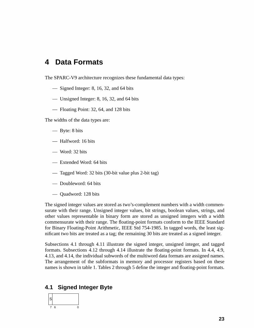
men-, andwidthdardsig-teger.
agged4.9,
ames.these
mats.
4 Data Formats
The SPARC-V9 architecture recognizes these fundamental data types:
— Signed Integer: 8, 16, 32, and 64 bits
— Unsigned Integer: 8, 16, 32, and 64 bits
— Floating Point: 32, 64, and 128 bits
The widths of the data types are:
— Byte: 8 bits
— Halfword: 16 bits
— Word: 32 bits
— Extended Word: 64 bits
— Tagged Word: 32 bits (30-bit value plus 2-bit tag)
— Doubleword: 64 bits
— Quadword: 128 bits
The signed integer values are stored as two’s-complement numbers with a width comsurate with their range. Unsigned integer values, bit strings, boolean values, stringsother values representable in binary form are stored as unsigned integers with acommensurate with their range. The floating-point formats conform to the IEEE Stanfor Binary Floating-Point Arithmetic, IEEE Std 754-1985. In tagged words, the leastnificant two bits are treated as a tag; the remaining 30 bits are treated as a signed in
Subsections 4.1 through 4.11 illustrate the signed integer, unsigned integer, and tformats. Subsections 4.12 through 4.14 illustrate the floating-point formats. In 4.4,4.13, and 4.14, the individual subwords of the multiword data formats are assigned nThe arrangement of the subformats in memory and processor registers based onnames is shown in table 1. Tables 2 through 5 define the integer and floating-point for
4.1 Signed Integer Byte
7 6 0
S
23
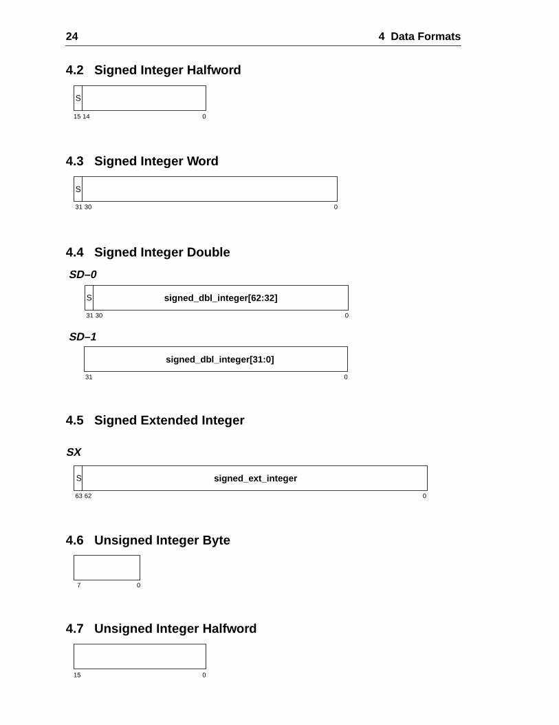
24 4 Data Formats
4.2 Signed Integer Halfword
4.3 Signed Integer Word
4.4 Signed Integer Double
4.5 Signed Extended Integer
SX
4.6 Unsigned Integer Byte
4.7 Unsigned Integer Halfword
15 14 0
S
31 30 0
S
31 30 0
S signed_dbl_integer[62:32]
SD–0
SD–1
31 0
signed_dbl_integer[31:0]
63 62 0
S signed_ext_integer
7 0
15 0
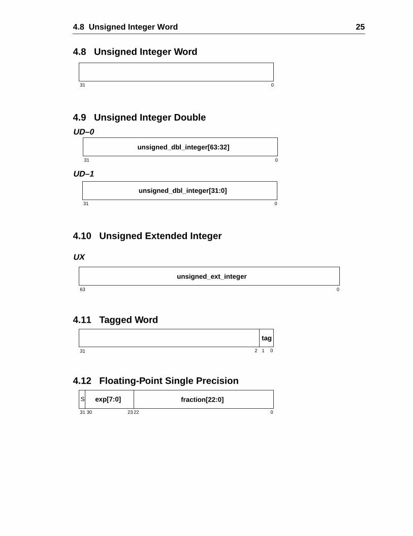
4.8 Unsigned Integer Word 25
4.8 Unsigned Integer Word
4.9 Unsigned Integer Double
4.10 Unsigned Extended Integer
UX
4.11 Tagged Word
4.12 Floating-Point Single Precision
31 0
31 0
unsigned_dbl_integer[63:32]
UD–0
UD–1
31 0
unsigned_dbl_integer[31:0]
63 0
unsigned_ext_integer
31 0
tag
2 1
31 30 0
S exp[7:0] fraction[22:0]
2223
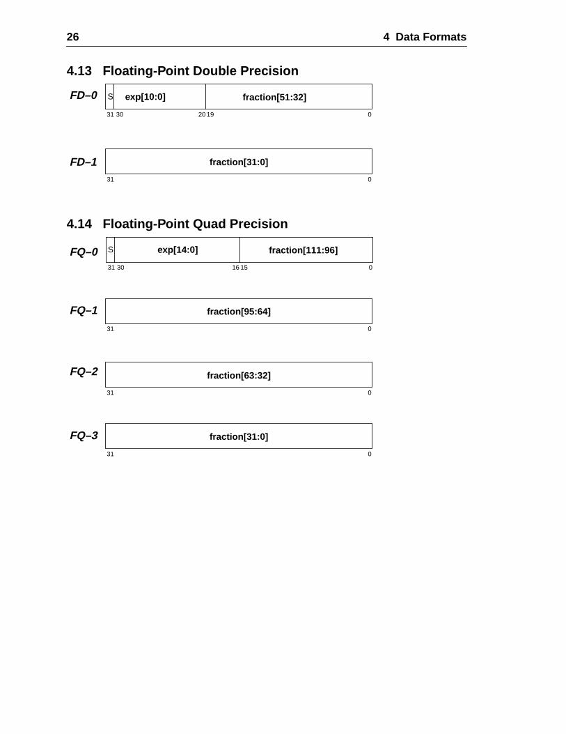
26 4 Data Formats
4.13 Floating-Point Double Precision
4.14 Floating-Point Quad Precision
31 30 0
S exp[10:0] fraction[51:32]
1920
FD–0
FD–131 0
fraction[31:0]
31 30 0
S exp[14:0] fraction[111:96]
1516
FQ–0
FQ–1
FQ–2
FQ–3
31 0
fraction[95:64]
31 0
fraction[63:32]
31 0
fraction[31:0]
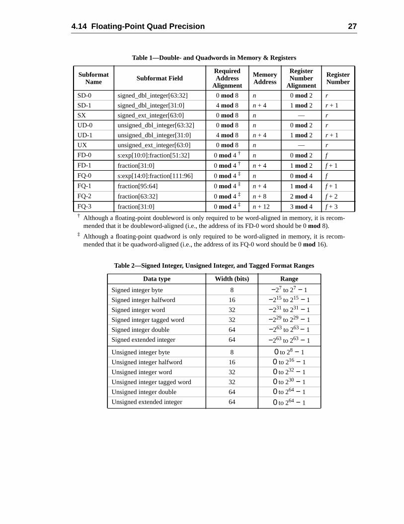
4.14 Floating-Point Quad Precision 27
† Although a floating-point doubleword is only required to be word-aligned in memory, it is recom-mended that it be doubleword-aligned (i.e., the address of its FD-0 word should be 0mod 8).
‡ Although a floating-point quadword is only required to be word-aligned in memory, it is recom-mended that it be quadword-aligned (i.e., the address of its FQ-0 word should be 0mod 16).
Table 1—Double- and Quadwords in Memory & Registers
SubformatName Subformat Field
RequiredAddress
Alignment
MemoryAddress
RegisterNumber
Alignment
RegisterNumber
SD-0 signed_dbl_integer[63:32] 0mod 8 n 0 mod 2 r
SD-1 signed_dbl_integer[31:0] 4mod 8 n + 4 1mod 2 r + 1
SX signed_ext_integer[63:0] 0mod 8 n — r
UD-0 unsigned_dbl_integer[63:32] 0mod 8 n 0 mod 2 r
UD-1 unsigned_dbl_integer[31:0] 4mod 8 n + 4 1mod 2 r + 1
UX unsigned_ext_integer[63:0] 0mod 8 n — r
FD-0 s:exp[10:0]:fraction[51:32] 0mod 4 † n 0 mod 2 f
FD-1 fraction[31:0] 0mod 4 † n + 4 1mod 2 f + 1
FQ-0 s:exp[14:0]:fraction[111:96] 0mod 4 ‡ n 0 mod 4 f
FQ-1 fraction[95:64] 0mod 4 ‡ n + 4 1mod 4 f + 1
FQ-2 fraction[63:32] 0mod 4 ‡ n + 8 2mod 4 f + 2
FQ-3 fraction[31:0] 0mod 4 ‡ n + 12 3mod 4 f + 3
Table 2—Signed Integer, Unsigned Integer, and Tagged Format Ranges
Data type Width (bits) Range
Signed integer byte 8 −27 to 27 − 1
Signed integer halfword 16 −215 to 215 − 1
Signed integer word 32 −231 to 231 − 1
Signed integer tagged word 32 −229 to 229 − 1
Signed integer double 64 −263 to 263− 1
Signed extended integer 64 −263 to 263 − 1
Unsigned integer byte 8 0 to 28 − 1
Unsigned integer halfword 16 0 to 216 − 1
Unsigned integer word 32 0 to 232 − 1
Unsigned integer tagged word 32 0 to 230 − 1
Unsigned integer double 64 0 to 264 − 1
Unsigned extended integer 64 0 to 264 − 1
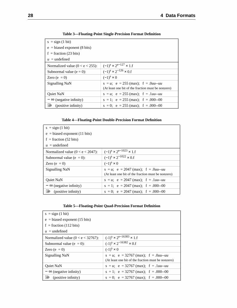
28 4 Data Formats
Table 3—Floating-Point Single-Precision Format Definition
s = sign (1 bit)
e = biased exponent (8 bits)
f = fraction (23 bits)
u = undefined
Normalized value (0 < e < 255): (−1)s × 2e−127× 1.f
Subnormal value (e = 0): (−1)s × 2−126× 0.f
Zero (e = 0) (−1)s × 0
Signalling NaN s =u; e = 255 (max); f = .0uu--uu(At least one bit of the fraction must be nonzero)
Quiet NaN s =u; e = 255 (max); f = .1uu--uu
− ∞ (negative infinity) s = 1; e = 255 (max); f = .000--00
+ ∞ (positive infinity) s = 0; e = 255 (max); f = .000--00
Table 4—Floating-Point Double-Precision Format Definition
s = sign (1 bit)
e = biased exponent (11 bits)
f = fraction (52 bits)
u = undefined
Normalized value (0 < e < 2047): (−1)s × 2e−1023× 1.f
Subnormal value (e = 0): (−1)s × 2−1022× 0.f
Zero (e = 0) (−1)s × 0
Signalling NaN s =u; e = 2047 (max); f = .0uu--uu(At least one bit of the fraction must be nonzero)
Quiet NaN s =u; e = 2047 (max); f = .1uu--uu
− ∞ (negative infinity) s = 1; e = 2047 (max); f = .000--00
+ ∞ (positive infinity) s = 0; e = 2047 (max); f = .000--00
Table 5—Floating-Point Quad-Precision Format Definition
s = sign (1 bit)
e = biased exponent (15 bits)
f = fraction (112 bits)
u = undefined
Normalized value (0 < e < 32767): (-1)s × 2e−16383× 1.f
Subnormal value (e = 0): (-1)s × 2−16382× 0.f
Zero (e = 0) (-1)s × 0
Signalling NaN s =u; e = 32767 (max); f = .0uu--uu(At least one bit of the fraction must be nonzero)
Quiet NaN s =u; e = 32767 (max); f = .1uu--uu
− ∞ (negative infinity) s = 1; e = 32767 (max); f = .000--00
+ ∞ (positive infinity) s = 0; e = 32767 (max); f = .000--00
rking
5 Registers
A SPARC-V9 processor includes two types of registers: general-purpose, (or wodata) registers, and control/status registers.
Working registers include:
— Integer working registers (r registers)
— Floating-point working registers (f registers)
Control/status registers include:
— Program Counter register (PC)
— Next Program Counter register (nPC)
— Processor State register (PSTATE)
— Trap Base Address register (TBA)
— Y register (Y)
— Processor Interrupt Level register (PIL)
— Current Window Pointer register (CWP)
— Trap Type register (TT)
— Condition Codes Register (CCR)
— Address Space Identifier register (ASI)
— Trap Level register (TL)
— Trap Program Counter register (TPC)
— Trap Next Program Counter register (TNPC)
— Trap State register (TSTATE)
— Hardware clock-tick counter register (TICK)
— Savable windows register (CANSAVE)
— Restorable windows register (CANRESTORE)
— Other windows register (OTHERWIN)
— Clean windows register (CLEANWIN)
— Window State register (WSTATE)
29
30 5 Registers
dep.
wide.ervedval-
n, or
wn in
dow
globallobal)or a
ffect.
RC-ures
— Version register (VER)
— Implementation-dependent Ancillary State Registers (ASRs) (impl. dep. #8)
— Implementation-dependent IU Deferred-Trap Queue (impl. dep. #16)
— Floating-Point State Register (FSR)
— Floating-Point Registers State register (FPRS)
— Implementation-dependent Floating-Point Deferred-Trap Queue (FQ) (impl.#24)
For convenience, some registers in this chapter are illustrated as fewer than 64 bitsAny bits not shown are reserved for future extensions to the architecture. Such resbits read as zeroes and, when written by software, should always be written with theues of those bits previously read from that register, or with zeroes.
5.1 Nonprivileged Registers
The registers described in this subsection are visible to nonprivileged (applicatio“user-mode”) software.
5.1.1 General Purpose r Registers
At any moment, general-purpose registers appear to nonprivileged software as shofigure 1.
An implementation of the IU may contain from 64 to 528 general-purpose 64-bitr regis-ters. They are partitioned into 8global registers, 8alternate globalregisters, plus animplementation-dependent number of 16-register sets (impl. dep. #2). A register winconsists of the current 8in registers, 8local registers, and 8out registers. See table 6.
5.1.1.1 Global r Registers
Registersr[0]..r[7] refer to a set of eight registers called the global registers (g0..g7). Atany time, one of two sets of eight registers is enabled and can be accessed as theregisters. Which set of globals is currently enabled is selected by the AG (alternate gfield in the PSTATE register. See 5.2.1, “Processor State Register (PSTATE),” fdescription of the AG field.
Global register zero (g0) always reads as zero; writes to it have no program-visible e
V8 Compatibility Note:
Since the PSTATE register is only writable by privileged software, existing nonprivileged SPAV8 software will operate correctly on a SPARC-V9 implementation if supervisor software ensthat nonprivileged software sees a consistent set of global registers.
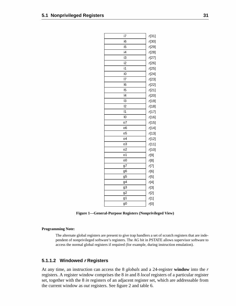
5.1 Nonprivileged Registers 31
re inde-re to
rfrom
Figure 1—General-Purpose Registers (Nonprivileged View)
Programming Note:
The alternate global registers are present to give trap handlers a set of scratch registers that apendent of nonprivileged software’s registers. The AG bit in PSTATE allows supervisor softwaaccess the normal global registers if required (for example, during instruction emulation).
5.1.1.2 Windowed r Registers
At any time, an instruction can access the 8globalsand a 24-registerwindow into therregisters. A register window comprises the 8in and 8local registers of a particular registeset, together with the 8in registers of an adjacent register set, which are addressablethe current window asout registers. See figure 2 and table 6.
i7 r[31]
i6 r[30]
i5 r[29]
i4 r[28]
i3 r[27]
i2 r[26]
i1 r[25]
i0 r[24]
r[23]
r[22]
r[21]
r[20]
r[19]
r[18]
r[17]
r[16]
r[15]
r[14]
r[13]
r[12]
r[11]
r[10]
r[9]
r[8]
r[7]
r[6]
r[5]
r[4]
r[3]
r[2]
r[1]
r[0]
l7
l6
l5
l4
l3
l2
l1
l0
o7
o6
o5
o4
o3
o2
o1
o0
g7
g6
g5
g4
g3
g2
g1
g0
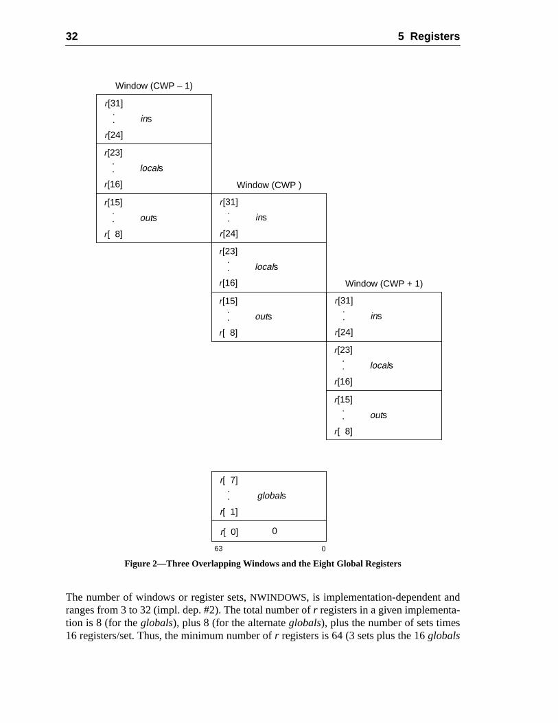
32 5 Registers
d-s
Figure 2—Three Overlapping Windows and the Eight Global Registers
The number of windows or register sets,NWINDOWS, is implementation-dependent anranges from 3 to 32 (impl. dep. #2). The total number ofr registers in a given implementation is 8 (for theglobals), plus 8 (for the alternateglobals), plus the number of sets time16 registers/set. Thus, the minimum number ofr registers is 64 (3 sets plus the 16globals
Window (CWP – 1)
r[31]
r[24]
ins..
r[23]
r[16]
locals..
r[15]
r[ 8]
outs..
Window (CWP )
r[31]
r[24]
ins..
r[23]
r[16]
locals..
r[15]
r[ 8]
outs..
Window (CWP + 1)
r[31]
r[24]
ins..
r[23]
r[16]
locals..
r[15]
r[ 8]
outs..
r[ 7]
r[ 1]
globals..
r[ 0] 0
63 0
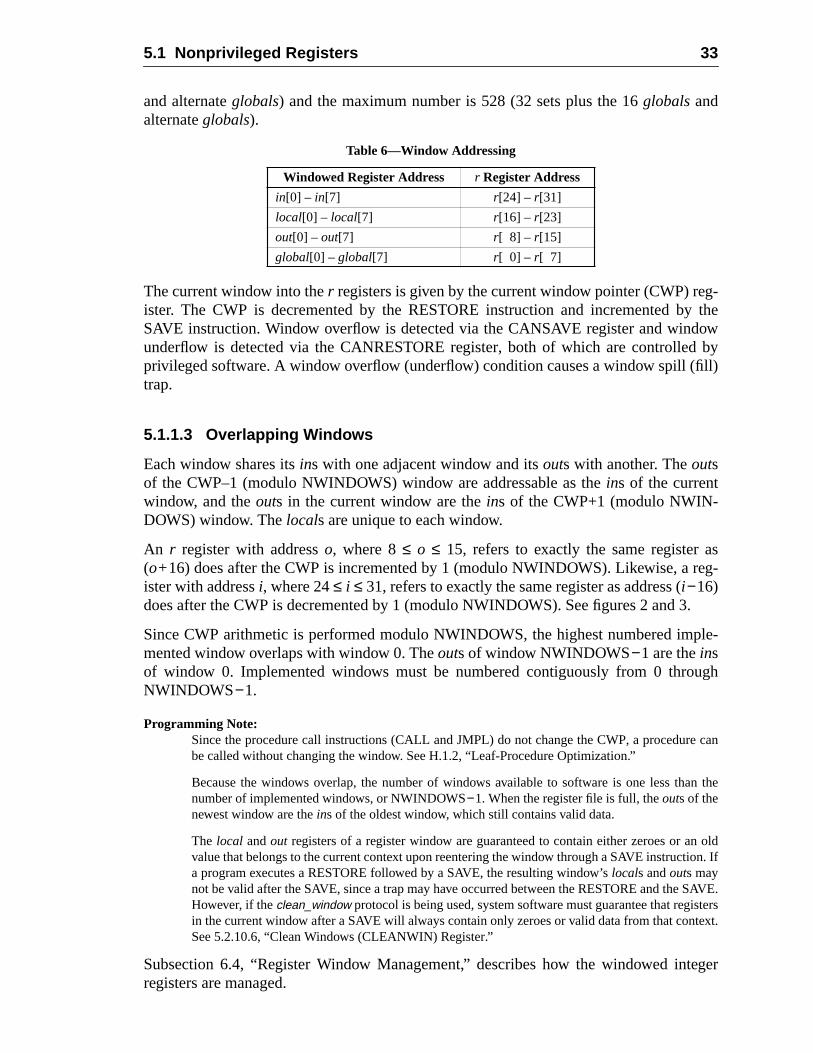
5.1 Nonprivileged Registers 33
g-y theow
byll)
asreg-
3.
ple-
ugh
e can
n the
n oldon. If
AVE.tersext.
teger
and alternateglobals) and the maximum number is 528 (32 sets plus the 16globalsandalternateglobals).
The current window into ther registers is given by the current window pointer (CWP) reister. The CWP is decremented by the RESTORE instruction and incremented bSAVE instruction. Window overflow is detected via the CANSAVE register and windunderflow is detected via the CANRESTORE register, both of which are controlledprivileged software. A window overflow (underflow) condition causes a window spill (fitrap.
5.1.1.3 Overlapping Windows
Each window shares itsins with one adjacent window and itsouts with another. Theoutsof the CWP–1 (modulo NWINDOWS) window are addressable as theins of the currentwindow, and theouts in the current window are theins of the CWP+1 (modulo NWIN-DOWS) window. Thelocals are unique to each window.
An r register with addresso, where 8≤ o ≤ 15, refers to exactly the same register(o+16) does after the CWP is incremented by 1 (modulo NWINDOWS). Likewise, aister with addressi, where 24≤ i ≤ 31, refers to exactly the same register as address (i −16)does after the CWP is decremented by 1 (modulo NWINDOWS). See figures 2 and
Since CWP arithmetic is performed modulo NWINDOWS, the highest numbered immented window overlaps with window 0. Theouts of window NWINDOWS−1 are theinsof window 0. Implemented windows must be numbered contiguously from 0 throNWINDOWS−1.
Programming Note:Since the procedure call instructions (CALL and JMPL) do not change the CWP, a procedurbe called without changing the window. See H.1.2, “Leaf-Procedure Optimization.”
Because the windows overlap, the number of windows available to software is one less thanumber of implemented windows, or NWINDOWS−1. When the register file is full, theouts of thenewest window are theins of the oldest window, which still contains valid data.
The local andout registers of a register window are guaranteed to contain either zeroes or avalue that belongs to the current context upon reentering the window through a SAVE instructia program executes a RESTORE followed by a SAVE, the resulting window’slocals andouts maynot be valid after the SAVE, since a trap may have occurred between the RESTORE and the SHowever, if theclean_window protocol is being used, system software must guarantee that regisin the current window after a SAVE will always contain only zeroes or valid data from that contSee 5.2.10.6, “Clean Windows (CLEANWIN) Register.”
Subsection 6.4, “Register Window Management,” describes how the windowed inregisters are managed.
Table 6—Window Addressing
Windowed Register Address r Register Address
in[0] – in[7] r[24] – r[31]
local[0] – local[7] r[16] – r[23]
out[0] – out[7] r[ 8] – r[15]
global[0] – global[7] r[ 0] – r[ 7]
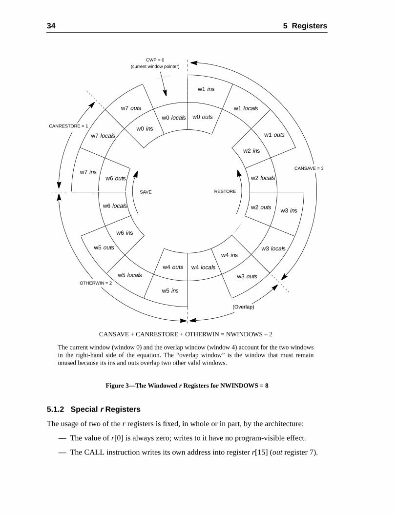
34 5 Registers
Figure 3—The Windowedr Registers for NWINDOWS = 8
5.1.2 Special r Registers
The usage of two of ther registers is fixed, in whole or in part, by the architecture:
— The value ofr[0] is always zero; writes to it have no program-visible effect.
— The CALL instruction writes its own address into registerr[15] (out register 7).
CWP = 0(current window pointer)
w1 outs
w2 outs
w3 outs
w4 outs
w5 outs
w6 outs
w7 outs
w0 outsw0 locals
w0 ins
w1 locals
w1 ins
w3 locals
w3 ins
w5 locals
w5 ins
w4 locals
w4 ins
w6 locals
w2 locals
w2 ins
w7 locals
w7 ins
RESTORESAVE
w6 ins
(Overlap)
OTHERWIN = 2
CANRESTORE = 1
CANSAVE = 3
CANSAVE + CANRESTORE + OTHERWIN = NWINDOWS – 2
The current window (window 0) and the overlap window (window 4) account for the two windowsin the right-hand side of the equation. The “overlap window” is the window that must remainunused because its ins and outs overlap two other valid windows.
5.1 Nonprivileged Registers 35
is
is-
,
nPC),ent
. Ther. The
sfers theringsfer.”
fcc,ruc-
5.1.2.1 Register-Pair Operands
LDD, LDDA, STD, and STDA instructions access a pair of words in adjacentr registersand require even-odd register alignment. The least-significant bit of anr register numberin these instructions is reserved, and should be supplied as zero by software.
When ther[0] – r[1] register pair is used as a destination in LDD or LDDA, onlyr[1] ismodified. When ther[0] – r[1] register pair is used as a source in STD or STDA, a zerowritten to the 32-bit word at the lowest address and the least significant 32 bits ofr[1] arewritten to the 32-bit word at the highest address (in big-endian mode).
An attempt to execute an LDD, LDDA, STD, or STDA instruction that refers to a maligned (odd) destination register number causes anillegal_instruction trap.
5.1.2.2 Register Usage
See H.1.1, “Registers,” for information about the conventional usage of ther registers.
In figure 3, NWINDOWS = 8. The 8globals are not illustrated. CWP = 0, CANSAVE = 3OTHERWIN = 2, and CANRESTORE = 1. If the procedure using windoww0 executes aRESTORE, windoww7 becomes the current window. If the procedure using windoww0executes a SAVE, windoww1 becomes the current window.
5.1.3 IU Control/Status Registers
The nonprivileged IU control/status registers include the program counters (PC andthe 32-bit multiply/divide (Y) register (and possibly optional) implementation-dependAncillary State Registers (ASRs) (impl. dep. #8).
5.1.3.1 Program Counters (PC, nPC)
The PC contains the address of the instruction currently being executed by the IUnPC holds the address of the next instruction to be executed, if a trap does not occulow-order two bits of PC and nPC always contain zero.
For a delayed control transfer, the instruction that immediately follows the traninstruction is known as the delay instruction. This delay instruction is executed (unlescontrol transfer instruction annuls it) before control is transferred to the target. Duexecution of the delay instruction, the nPC points to the target of the control traninstruction, while the PC points to the delay instruction. See Chapter 6, “Instructions
The PC is used implicitly as a destination register by CALL, Bicc, BPcc, BPr, FBFBPfcc, JMPL, and RETURN instructions. It can be read directly by an RDPC insttion.
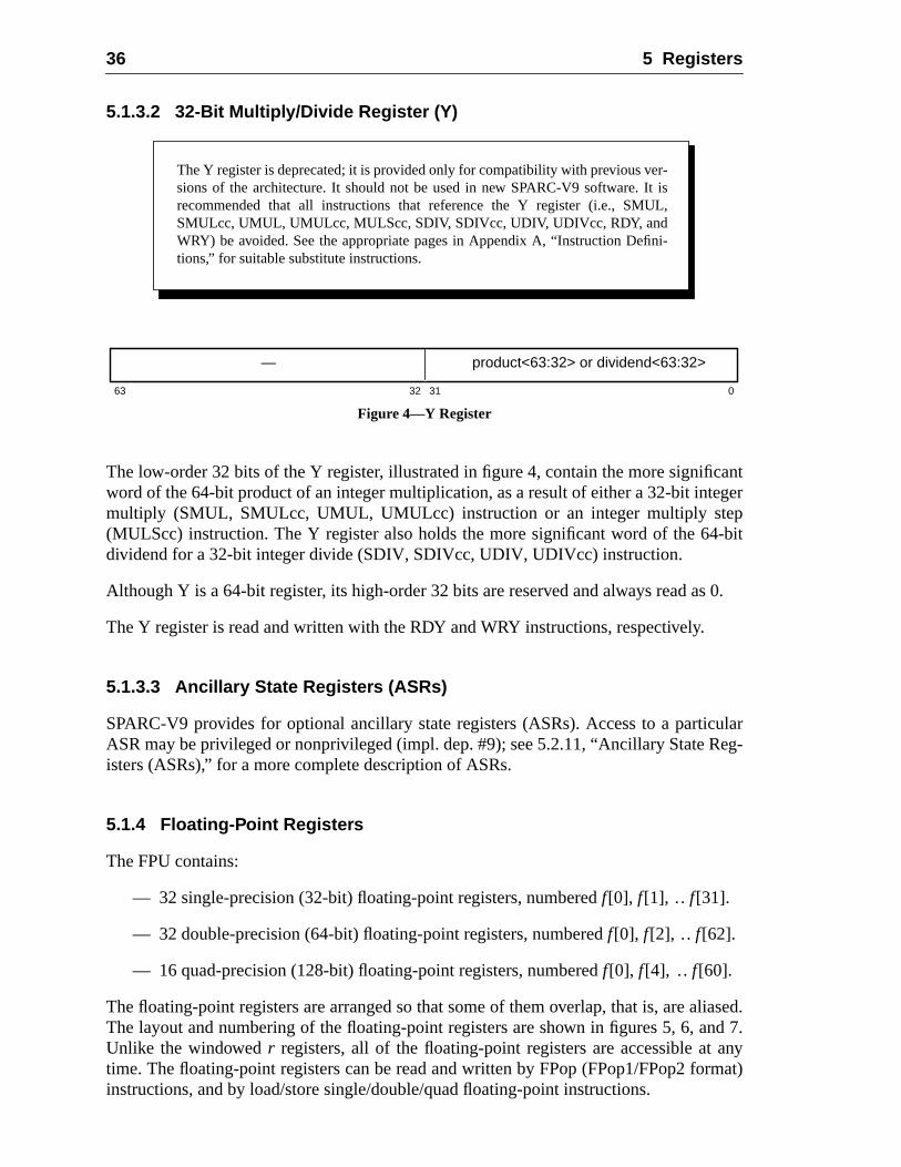
36 5 Registers
antger
-bit
s 0.
ulareg-
liased.nd 7.anyrmat)
5.1.3.2 32-Bit Multiply/Divide Register (Y)
Figure 4—Y Register
The low-order 32 bits of the Y register, illustrated in figure 4, contain the more significword of the 64-bit product of an integer multiplication, as a result of either a 32-bit intemultiply (SMUL, SMULcc, UMUL, UMULcc) instruction or an integer multiply step(MULScc) instruction. The Y register also holds the more significant word of the 64dividend for a 32-bit integer divide (SDIV, SDIVcc, UDIV, UDIVcc) instruction.
Although Y is a 64-bit register, its high-order 32 bits are reserved and always read a
The Y register is read and written with the RDY and WRY instructions, respectively.
5.1.3.3 Ancillary State Registers (ASRs)
SPARC-V9 provides for optional ancillary state registers (ASRs). Access to a particASR may be privileged or nonprivileged (impl. dep. #9); see 5.2.11, “Ancillary State Risters (ASRs),” for a more complete description of ASRs.
5.1.4 Floating-Point Registers
The FPU contains:
— 32 single-precision (32-bit) floating-point registers, numberedf[0], f [1], .. f[31].
— 32 double-precision (64-bit) floating-point registers, numberedf[0], f[2], .. f[62].
— 16 quad-precision (128-bit) floating-point registers, numberedf[0], f [4], .. f[60].
The floating-point registers are arranged so that some of them overlap, that is, are aThe layout and numbering of the floating-point registers are shown in figures 5, 6, aUnlike the windowedr registers, all of the floating-point registers are accessible attime. The floating-point registers can be read and written by FPop (FPop1/FPop2 foinstructions, and by load/store single/double/quad floating-point instructions.
The Y register is deprecated; it is provided only for compatibility with previous ver-sions of the architecture. It should not be used in new SPARC-V9 software. It isrecommended that all instructions that reference the Y register (i.e., SMUL,SMULcc, UMUL, UMULcc, MULScc, SDIV, SDIVcc, UDIV, UDIVcc, RDY, andWRY) be avoided. See the appropriate pages in Appendix A, “Instruction Defini-tions,” for suitable substitute instructions.
63 032 31
— product<63:32> or dividend<63:32>
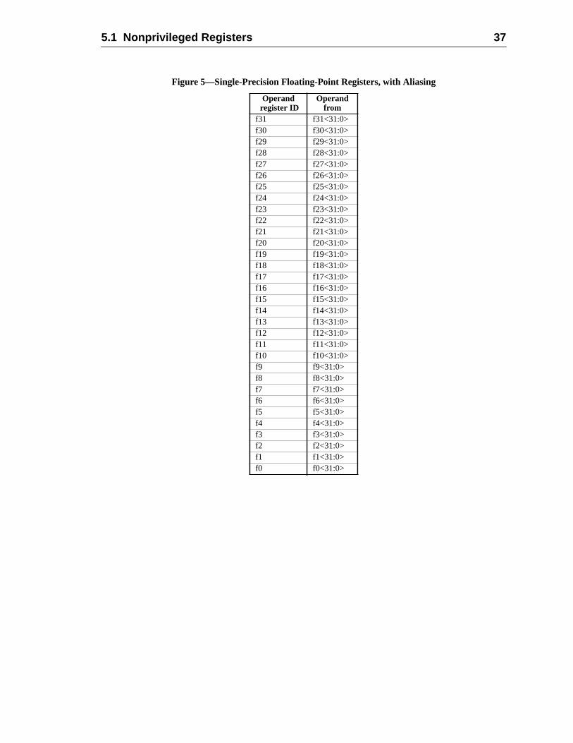
5.1 Nonprivileged Registers 37
Figure 5—Single-Precision Floating-Point Registers, with Aliasing
Operand register ID
Operandfrom
f31 f31<31:0>f30 f30<31:0>f29 f29<31:0>f28 f28<31:0>f27 f27<31:0>f26 f26<31:0>f25 f25<31:0>f24 f24<31:0>f23 f23<31:0>f22 f22<31:0>f21 f21<31:0>f20 f20<31:0>f19 f19<31:0>f18 f18<31:0>f17 f17<31:0>f16 f16<31:0>f15 f15<31:0>f14 f14<31:0>f13 f13<31:0>f12 f12<31:0>f11 f11<31:0>f10 f10<31:0>f9 f9<31:0>f8 f8<31:0>f7 f7<31:0>f6 f6<31:0>f5 f5<31:0>f4 f4<31:0>f3 f3<31:0>f2 f2<31:0>f1 f1<31:0>f0 f0<31:0>
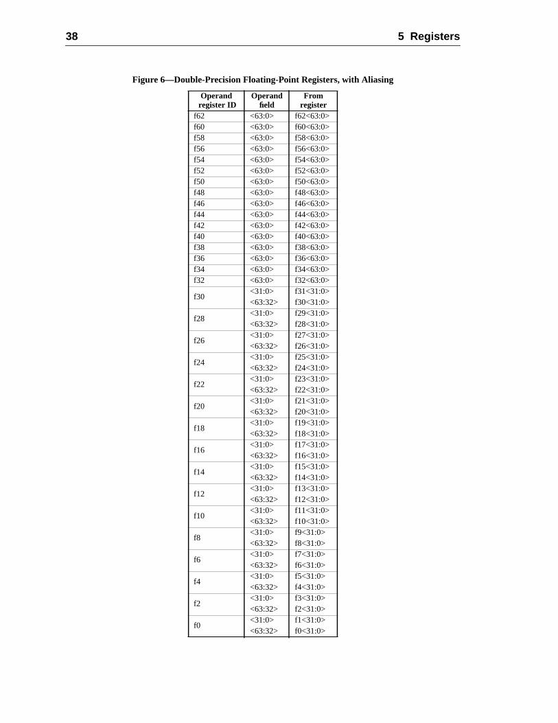
38 5 Registers
Figure 6—Double-Precision Floating-Point Registers, with Aliasing
Operand register ID
Operandfield
Fromregister
f62 <63:0> f62<63:0>f60 <63:0> f60<63:0>f58 <63:0> f58<63:0>f56 <63:0> f56<63:0>f54 <63:0> f54<63:0>f52 <63:0> f52<63:0>f50 <63:0> f50<63:0>f48 <63:0> f48<63:0>f46 <63:0> f46<63:0>f44 <63:0> f44<63:0>f42 <63:0> f42<63:0>f40 <63:0> f40<63:0>f38 <63:0> f38<63:0>f36 <63:0> f36<63:0>f34 <63:0> f34<63:0>f32 <63:0> f32<63:0>
f30<31:0> f31<31:0><63:32> f30<31:0>
f28<31:0> f29<31:0><63:32> f28<31:0>
f26<31:0> f27<31:0><63:32> f26<31:0>
f24<31:0> f25<31:0><63:32> f24<31:0>
f22<31:0> f23<31:0><63:32> f22<31:0>
f20<31:0> f21<31:0><63:32> f20<31:0>
f18<31:0> f19<31:0><63:32> f18<31:0>
f16<31:0> f17<31:0><63:32> f16<31:0>
f14<31:0> f15<31:0><63:32> f14<31:0>
f12<31:0> f13<31:0><63:32> f12<31:0>
f10<31:0> f11<31:0><63:32> f10<31:0>
f8<31:0> f9<31:0><63:32> f8<31:0>
f6<31:0> f7<31:0><63:32> f6<31:0>
f4<31:0> f5<31:0><63:32> f4<31:0>
f2<31:0> f3<31:0><63:32> f2<31:0>
f0<31:0> f1<31:0><63:32> f0<31:0>
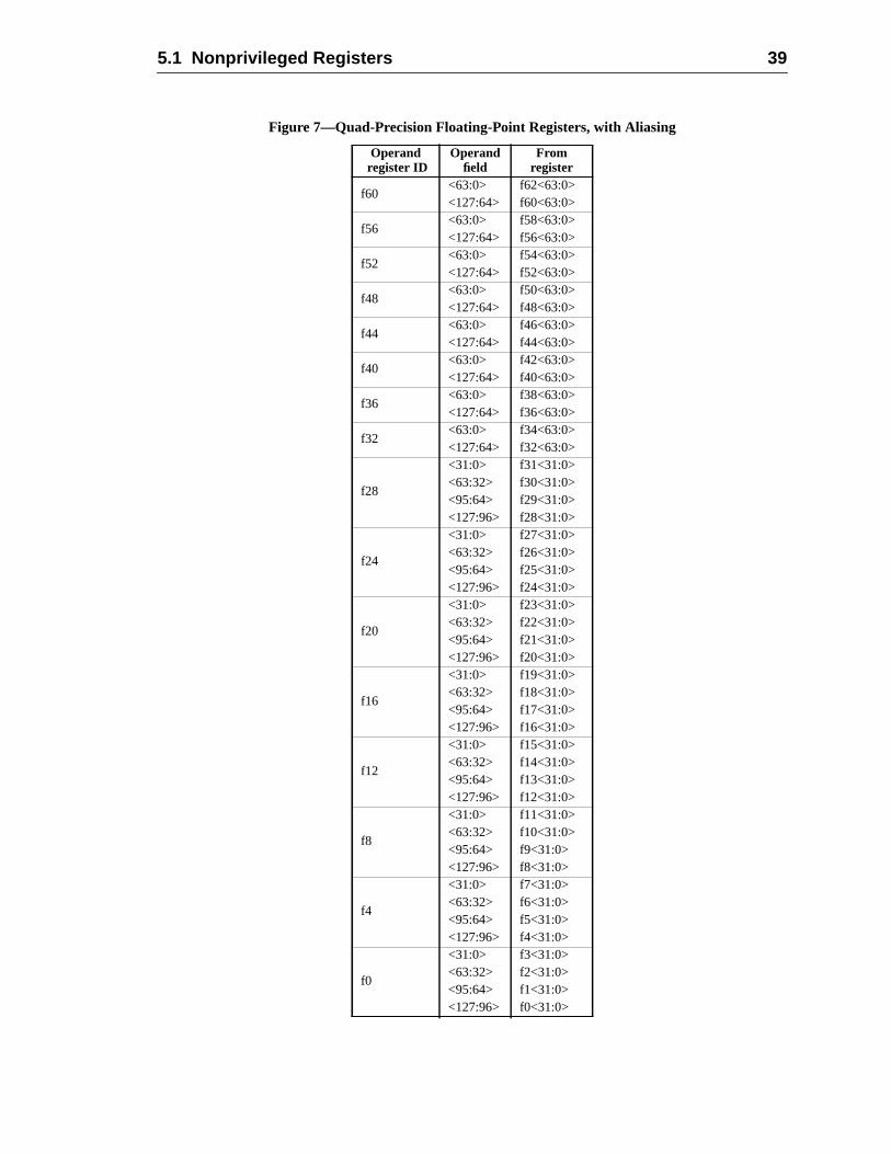
5.1 Nonprivileged Registers 39
Figure 7—Quad-Precision Floating-Point Registers, with Aliasing
Operand register ID
Operandfield
Fromregister
f60<63:0> f62<63:0><127:64> f60<63:0>
f56<63:0> f58<63:0><127:64> f56<63:0>
f52<63:0> f54<63:0><127:64> f52<63:0>
f48<63:0> f50<63:0><127:64> f48<63:0>
f44<63:0> f46<63:0><127:64> f44<63:0>
f40<63:0> f42<63:0><127:64> f40<63:0>
f36<63:0> f38<63:0><127:64> f36<63:0>
f32<63:0> f34<63:0><127:64> f32<63:0>
f28
<31:0> f31<31:0><63:32> f30<31:0><95:64> f29<31:0><127:96> f28<31:0>
f24
<31:0> f27<31:0><63:32> f26<31:0><95:64> f25<31:0><127:96> f24<31:0>
f20
<31:0> f23<31:0><63:32> f22<31:0><95:64> f21<31:0><127:96> f20<31:0>
f16
<31:0> f19<31:0><63:32> f18<31:0><95:64> f17<31:0><127:96> f16<31:0>
f12
<31:0> f15<31:0><63:32> f14<31:0><95:64> f13<31:0><127:96> f12<31:0>
f8
<31:0> f11<31:0><63:32> f10<31:0><95:64> f9<31:0><127:96> f8<31:0>
f4
<31:0> f7<31:0><63:32> f6<31:0><95:64> f5<31:0><127:96> f4<31:0>
f0
<31:0> f3<31:0><63:32> f2<31:0><95:64> f1<31:0><127:96> f0<31:0>
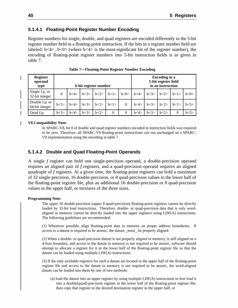
40 5 Registers
5-bitare
, thein
uiredRC-
randnedumlf of
ision
rectlyord-
ions.
s. If
on ahouldthe
pointigned
d itle,
5.1.4.1 Floating-Point Register Number Encoding
Register numbers for single, double, and quad registers are encoded differently in theregister number field in a floating-point instruction. If the bits in a register number fieldlabeled: b<4>..b<0> (where b<4> is the most-significant bit of the register number)encoding of floating-point register numbers into 5-bit instruction fields is as giventable 7.
V8 Compatibility Note:In SPARC-V8, bit 0 of double and quad register numbers encoded in instruction fields was reqto be zero. Therefore, all SPARC-V8 floating-point instructions can run unchanged on a SPAV9 implementation using the encoding in table 7.
5.1.4.2 Double and Quad Floating-Point Operands
A single f register can hold one single-precision operand, a double-precision operequires an aligned pair off registers, and a quad-precision operand requires an aligquadruple off registers. At a given time, the floating-point registers can hold a maximof 32 single-precision, 16 double-precision, or 8 quad-precision values in the lower hathe floating-point register file, plus an additional 16 double-precision or 8 quad-precvalues in the upper half, or mixtures of the three sizes.
Programming Note:The upper 16 double-precision (upper 8 quad-precision) floating-point registers cannot be diloaded by 32-bit load instructions. Therefore, double- or quad-precision data that is only waligned in memory cannot be directly loaded into the upper registers using LDF(A) instructThe following guidelines are recommended:
(1) Whenever possible, align floating-point data in memory on proper address boundarieaccess to a datum is required to be atomic, the datum _must_ be properly aligned.
(2) When a double- or quad-precision datum is not properly aligned in memory, is still aligned4-byte boundary, and access to the datum in memory is not required to be atomic, software sattempt to allocate a register for it in the lower half of the floating-point register file so thatdatum can be loaded using multiple LDF(A) instructions.
(3) If the only available registers for such a datum are located in the upper half of the floating-register file and access to the datum in memory is not required to be atomic, the word-aldatum can be loaded into them by one of two methods:
(a) load the datum into an upper register by using multiple LDF(A) instructions to first loainto a double[quad]-precision register in the lower half of the floating-point register fithen copy that register to the desired destination register in the upper half, or
Table 7—Floating-Point Register Number Encoding
Registeroperand
type 6-bit register number
Encoding in a5-bit register fieldin an instruction
Single f.p. or32-bit integer
0 b<4> b<3> b<2> b<1> b<0> b<4> b<3> b<2> b<1> b<0>
Double f.p. or64-bit integer
b<5> b<4> b<3> b<2> b<1> 0 b<4> b<3> b<2> b<1> b<5>
Quad f.p. b<5> b<4> b<3> b<2> 0 0 b<4> b<3> b<2> 0 b<5>
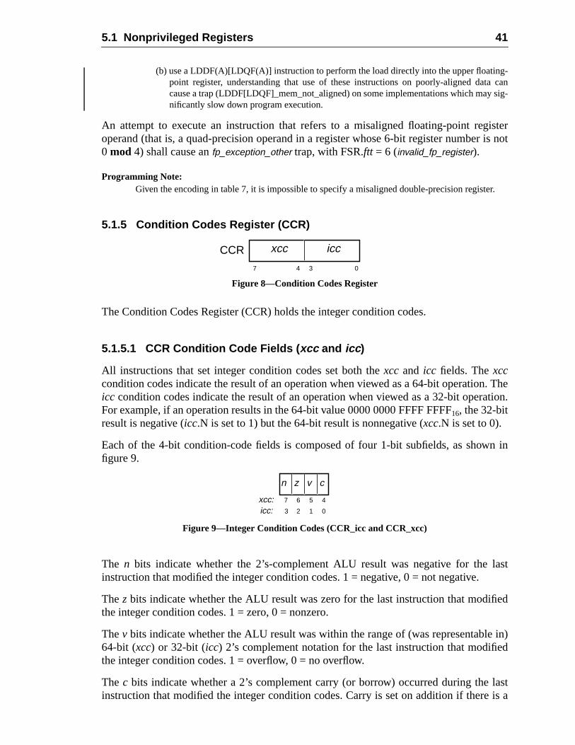
5.1 Nonprivileged Registers 41
g-can
sig-
isteris not
er.
. Thetion.
n in
last
fied
e in)d
lastis a
(b) use a LDDF(A)[LDQF(A)] instruction to perform the load directly into the upper floatinpoint register, understanding that use of these instructions on poorly-aligned datacause a trap (LDDF[LDQF]_mem_not_aligned) on some implementations which maynificantly slow down program execution.
An attempt to execute an instruction that refers to a misaligned floating-point regoperand (that is, a quad-precision operand in a register whose 6-bit register number0 mod 4) shall cause anfp_exception_other trap, with FSR.ftt = 6 (invalid_fp_register).
Programming Note:Given the encoding in table 7, it is impossible to specify a misaligned double-precision regist
5.1.5 Condition Codes Register (CCR)
Figure 8—Condition Codes Register
The Condition Codes Register (CCR) holds the integer condition codes.
5.1.5.1 CCR Condition Code Fields ( xcc and icc )
All instructions that set integer condition codes set both thexcc and icc fields. Thexcccondition codes indicate the result of an operation when viewed as a 64-bit operationicc condition codes indicate the result of an operation when viewed as a 32-bit operaFor example, if an operation results in the 64-bit value 0000 0000 FFFF FFFF16, the 32-bitresult is negative (icc.N is set to 1) but the 64-bit result is nonnegative (xcc.N is set to 0).
Each of the 4-bit condition-code fields is composed of four 1-bit subfields, as showfigure 9.
Figure 9—Integer Condition Codes (CCR_icc and CCR_xcc)
The n bits indicate whether the 2’s-complement ALU result was negative for theinstruction that modified the integer condition codes. 1 = negative, 0 = not negative.
Thez bits indicate whether the ALU result was zero for the last instruction that modithe integer condition codes. 1 = zero, 0 = nonzero.
Thev bits indicate whether the ALU result was within the range of (was representabl64-bit (xcc) or 32-bit (icc) 2’s complement notation for the last instruction that modifiethe integer condition codes. 1 = overflow, 0 = no overflow.
The c bits indicate whether a 2’s complement carry (or borrow) occurred during theinstruction that modified the integer condition codes. Carry is set on addition if there
7 4 03
xcc iccCCR
7 5 4
0
6
13 2
xcc:icc:
cvn z
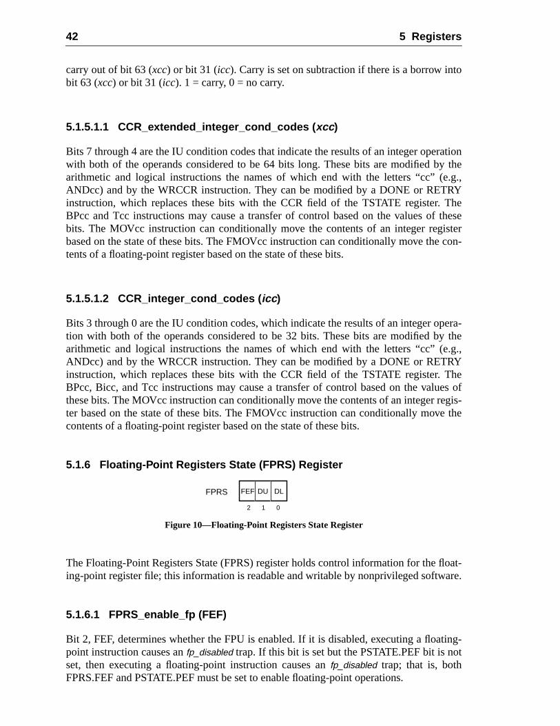
42 5 Registers
to
ationy the.g.,RYThethese
istercon-
pera-y the.g.,RYThees of
egis-e the
oat-are.
ting-t
carry out of bit 63 (xcc) or bit 31 (icc). Carry is set on subtraction if there is a borrow inbit 63 (xcc) or bit 31 (icc). 1 = carry, 0 = no carry.
5.1.5.1.1 CCR_extended_integer_cond_codes ( xcc )
Bits 7 through 4 are the IU condition codes that indicate the results of an integer operwith both of the operands considered to be 64 bits long. These bits are modified barithmetic and logical instructions the names of which end with the letters “cc” (eANDcc) and by the WRCCR instruction. They can be modified by a DONE or RETinstruction, which replaces these bits with the CCR field of the TSTATE register.BPcc and Tcc instructions may cause a transfer of control based on the values ofbits. The MOVcc instruction can conditionally move the contents of an integer regbased on the state of these bits. The FMOVcc instruction can conditionally move thetents of a floating-point register based on the state of these bits.
5.1.5.1.2 CCR_integer_cond_codes ( icc )
Bits 3 through 0 are the IU condition codes, which indicate the results of an integer otion with both of the operands considered to be 32 bits. These bits are modified barithmetic and logical instructions the names of which end with the letters “cc” (eANDcc) and by the WRCCR instruction. They can be modified by a DONE or RETinstruction, which replaces these bits with the CCR field of the TSTATE register.BPcc, Bicc, and Tcc instructions may cause a transfer of control based on the valuthese bits. The MOVcc instruction can conditionally move the contents of an integer rter based on the state of these bits. The FMOVcc instruction can conditionally movcontents of a floating-point register based on the state of these bits.
5.1.6 Floating-Point Registers State (FPRS) Register
Figure 10—Floating-Point Registers State Register
The Floating-Point Registers State (FPRS) register holds control information for the fling-point register file; this information is readable and writable by nonprivileged softw
5.1.6.1 FPRS_enable_fp (FEF)
Bit 2, FEF, determines whether the FPU is enabled. If it is disabled, executing a floapoint instruction causes anfp_disabled trap. If this bit is set but the PSTATE.PEF bit is noset, then executing a floating-point instruction causes anfp_disabled trap; that is, bothFPRS.FEF and PSTATE.PEF must be set to enable floating-point operations.
012
DLFEF DUFPRS
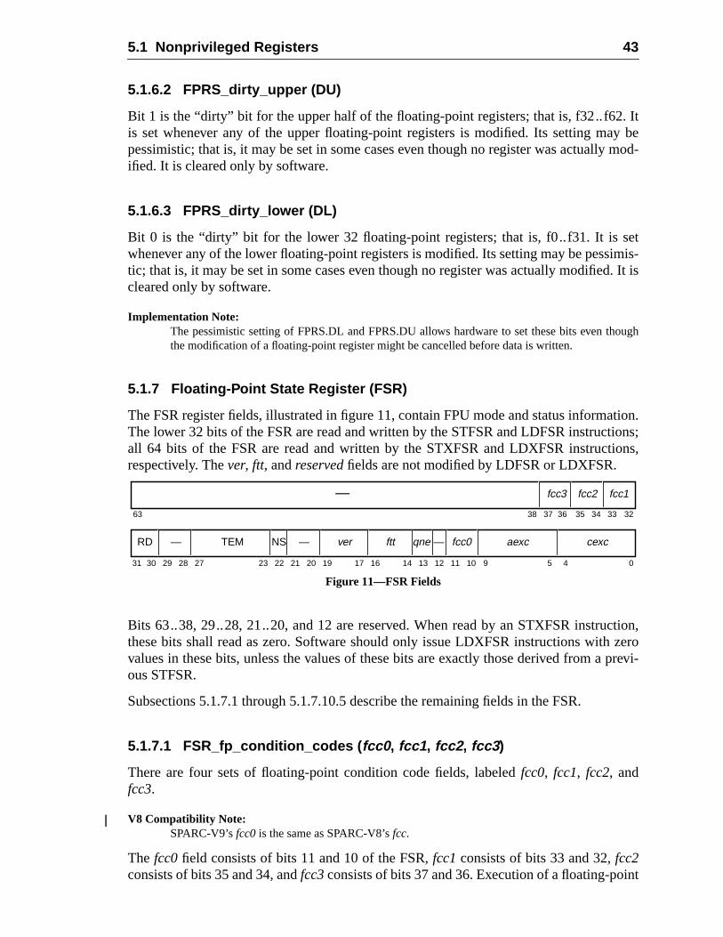
5.1 Nonprivileged Registers 43
Ity bemod-
etimis-. It is
hough
tion.ions;ons,
ction,zeroprevi-
nt
5.1.6.2 FPRS_dirty_upper (DU)
Bit 1 is the “dirty” bit for the upper half of the floating-point registers; that is, f32..f62.is set whenever any of the upper floating-point registers is modified. Its setting mapessimistic; that is, it may be set in some cases even though no register was actuallyified. It is cleared only by software.
5.1.6.3 FPRS_dirty_lower (DL)
Bit 0 is the “dirty” bit for the lower 32 floating-point registers; that is, f0..f31. It is swhenever any of the lower floating-point registers is modified. Its setting may be pesstic; that is, it may be set in some cases even though no register was actually modifiedcleared only by software.
Implementation Note:The pessimistic setting of FPRS.DL and FPRS.DU allows hardware to set these bits even tthe modification of a floating-point register might be cancelled before data is written.
5.1.7 Floating-Point State Register (FSR)
The FSR register fields, illustrated in figure 11, contain FPU mode and status informaThe lower 32 bits of the FSR are read and written by the STFSR and LDFSR instructall 64 bits of the FSR are read and written by the STXFSR and LDXFSR instructirespectively. Thever, ftt, andreserved fields are not modified by LDFSR or LDXFSR.
Figure 11—FSR Fields
Bits 63..38, 29..28, 21..20, and 12 are reserved. When read by an STXFSR instruthese bits shall read as zero. Software should only issue LDXFSR instructions withvalues in these bits, unless the values of these bits are exactly those derived from aous STFSR.
Subsections 5.1.7.1 through 5.1.7.10.5 describe the remaining fields in the FSR.
5.1.7.1 FSR_fp_condition_codes ( fcc0 , fcc1 , fcc2 , fcc3 )
There are four sets of floating-point condition code fields, labeledfcc0, fcc1, fcc2, andfcc3.
V8 Compatibility Note:SPARC-V9’sfcc0 is the same as SPARC-V8’sfcc.
The fcc0field consists of bits 11 and 10 of the FSR,fcc1consists of bits 33 and 32,fcc2consists of bits 35 and 34, andfcc3consists of bits 37 and 36. Execution of a floating-poi
63 3235 34 3338 37
31 141923 13 12 11 5 4 091017 162730 29 28 22 21 20
36
fcc3 fcc2 fcc1—
RD — TEM NS — ver ftt qne — fcc0 aexc cexc
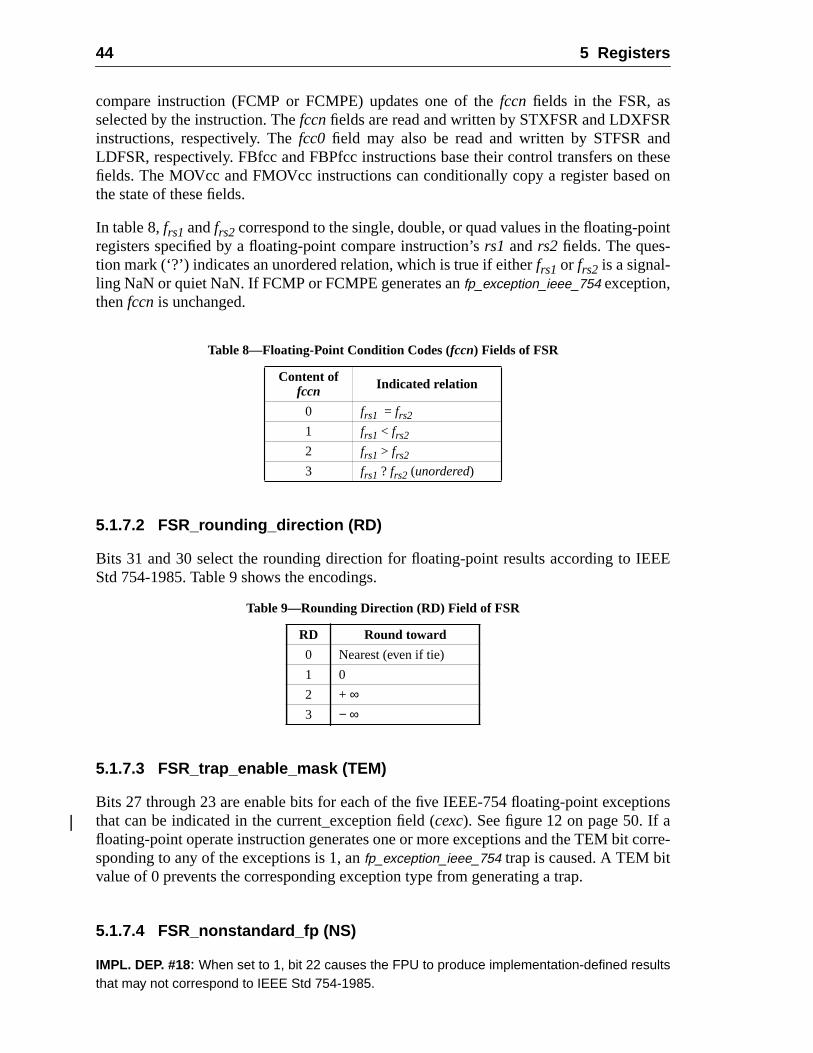
44 5 Registers
Rd
thesed on
oint
EE
tions
orre-
compare instruction (FCMP or FCMPE) updates one of thefccn fields in the FSR, asselected by the instruction. Thefccnfields are read and written by STXFSR and LDXFSinstructions, respectively. Thefcc0 field may also be read and written by STFSR anLDFSR, respectively. FBfcc and FBPfcc instructions base their control transfers onfields. The MOVcc and FMOVcc instructions can conditionally copy a register basethe state of these fields.
In table 8,frs1 andfrs2 correspond to the single, double, or quad values in the floating-pregisters specified by a floating-point compare instruction’srs1 andrs2 fields. The ques-tion mark (‘?’) indicates an unordered relation, which is true if eitherfrs1 or frs2 is a signal-ling NaN or quiet NaN. If FCMP or FCMPE generates anfp_exception_ieee_754 exception,thenfccn is unchanged.
5.1.7.2 FSR_rounding_direction (RD)
Bits 31 and 30 select the rounding direction for floating-point results according to IEStd 754-1985. Table 9 shows the encodings.
5.1.7.3 FSR_trap_enable_mask (TEM)
Bits 27 through 23 are enable bits for each of the five IEEE-754 floating-point excepthat can be indicated in the current_exception field (cexc). See figure 12 on page 50. If afloating-point operate instruction generates one or more exceptions and the TEM bit csponding to any of the exceptions is 1, anfp_exception_ieee_754 trap is caused. A TEM bitvalue of 0 prevents the corresponding exception type from generating a trap.
5.1.7.4 FSR_nonstandard_fp (NS)
IMPL. DEP. #18: When set to 1, bit 22 causes the FPU to produce implementation-defined resultsthat may not correspond to IEEE Std 754-1985.
Table 8—Floating-Point Condition Codes (fccn) Fields of FSR
Content offccn Indicated relation
0 frs1 = frs2
1 frs1 < frs2
2 frs1 > frs2
3 frs1 ? frs2 (unordered)
Table 9—Rounding Direction (RD) Field of FSR
RD Round toward
0 Nearest (even if tie)
1 0
2 + ∞3 − ∞
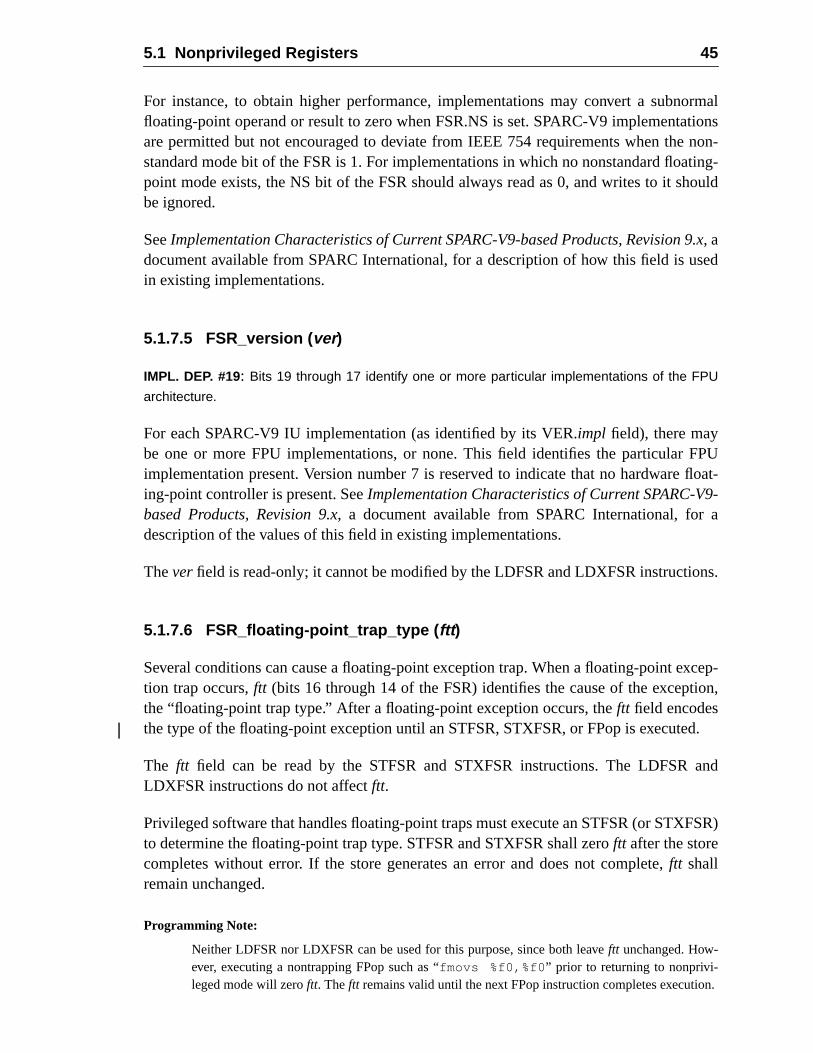
5.1 Nonprivileged Registers 45
ormaltionsnon-ting-ould
9.xsed
FPUfloat-9-a
ns.
xcep-ion,
ed.
and
FSR)
n.
For instance, to obtain higher performance, implementations may convert a subnfloating-point operand or result to zero when FSR.NS is set. SPARC-V9 implementaare permitted but not encouraged to deviate from IEEE 754 requirements when thestandard mode bit of the FSR is 1. For implementations in which no nonstandard floapoint mode exists, the NS bit of the FSR should always read as 0, and writes to it shbe ignored.
SeeImplementation Characteristics of Current SPARC-V9-based Products, Revision, adocument available from SPARC International, for a description of how this field is uin existing implementations.
5.1.7.5 FSR_version ( ver)
IMPL. DEP. #19: Bits 19 through 17 identify one or more particular implementations of the FPU
architecture.
For each SPARC-V9 IU implementation (as identified by its VER.impl field), there maybe one or more FPU implementations, or none. This field identifies the particularimplementation present. Version number 7 is reserved to indicate that no hardwareing-point controller is present. SeeImplementation Characteristics of Current SPARC-Vbased Products, Revision 9.x, a document available from SPARC International, fordescription of the values of this field in existing implementations.
Theverfield is read-only; it cannot be modified by the LDFSR and LDXFSR instructio
5.1.7.6 FSR_floating-point_trap_type ( ftt )
Several conditions can cause a floating-point exception trap. When a floating-point etion trap occurs,ftt (bits 16 through 14 of the FSR) identifies the cause of the exceptthe “floating-point trap type.” After a floating-point exception occurs, theftt field encodesthe type of the floating-point exception until an STFSR, STXFSR, or FPop is execut
The ftt field can be read by the STFSR and STXFSR instructions. The LDFSRLDXFSR instructions do not affectftt.
Privileged software that handles floating-point traps must execute an STFSR (or STXto determine the floating-point trap type. STFSR and STXFSR shall zeroftt after the storecompletes without error. If the store generates an error and does not complete,ftt shallremain unchanged.
Programming Note:
Neither LDFSR nor LDXFSR can be used for this purpose, since both leaveftt unchanged. How-ever, executing a nontrapping FPop such as “fmovs %f0,%f0 ” prior to returning to nonprivi-leged mode will zeroftt. Theftt remains valid until the next FPop instruction completes executio
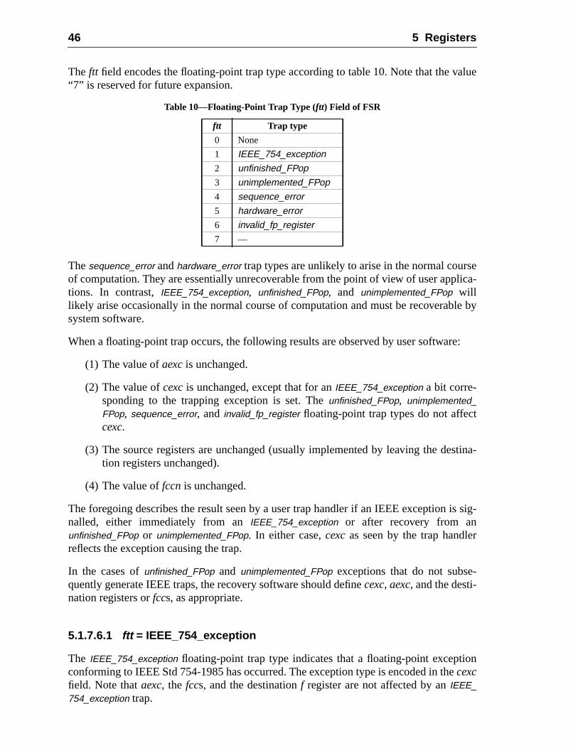
46 5 Registers
alue
selica-
le by
re:
t
stina-
is sig-
r
-
on
The ftt field encodes the floating-point trap type according to table 10. Note that the v“7” is reserved for future expansion.
Thesequence_error andhardware_error trap types are unlikely to arise in the normal courof computation. They are essentially unrecoverable from the point of view of user apptions. In contrast,IEEE_754_exception, unfinished_FPop, and unimplemented_FPop willlikely arise occasionally in the normal course of computation and must be recoverabsystem software.
When a floating-point trap occurs, the following results are observed by user softwa
(1) The value ofaexc is unchanged.
(2) The value ofcexcis unchanged, except that for anIEEE_754_exception a bit corre-sponding to the trapping exception is set. Theunfinished_FPop, unimplemented_FPop, sequence_error, and invalid_fp_register floating-point trap types do not affeccexc.
(3) The source registers are unchanged (usually implemented by leaving the detion registers unchanged).
(4) The value offccn is unchanged.
The foregoing describes the result seen by a user trap handler if an IEEE exceptionnalled, either immediately from anIEEE_754_exception or after recovery from anunfinished_FPop or unimplemented_FPop. In either case,cexcas seen by the trap handlereflects the exception causing the trap.
In the cases ofunfinished_FPop and unimplemented_FPop exceptions that do not subsequently generate IEEE traps, the recovery software should definecexc, aexc, and the desti-nation registers orfccs, as appropriate.
5.1.7.6.1 ftt = IEEE_754_exception
The IEEE_754_exception floating-point trap type indicates that a floating-point excepticonforming to IEEE Std 754-1985 has occurred. The exception type is encoded in thecexcfield. Note thataexc, the fccs, and the destinationf register are not affected by anIEEE_754_exception trap.
Table 10—Floating-Point Trap Type (ftt) Field of FSR
ftt Trap type
0 None
1 IEEE_754_exception
2 unfinished_FPop
3 unimplemented_FPop
4 sequence_error
5 hardware_error
6 invalid_fp_register
7 —
5.1 Nonprivileged Registers 47
as-1985
U
r
di-
n an
was-
ser-ious
ith a
thee user
phic
ient
5.1.7.6.2 ftt = unfinished_FPop
The unfinished_FPop floating-point trap type indicates that an implementation’s FPU wunable to generate correct results, or that exceptions as defined by IEEE Std 754have occurred. In the latter case, thecexc field is unchanged.
5.1.7.6.3 ftt = unimplemented_FPop
The unimplemented_FPop floating-point trap type indicates that an implementation’s FPdecoded an FPop that it does not implement. In this case, thecexc field is unchanged.
Programming Note:For theunfinished_FPop andunimplemented_FPop floating-point traps, software should emulate oreexecute the exception-causing instruction and update the FSR, destinationf register(s), andfccs.
5.1.7.6.4 ftt = sequence_error
The sequence_error floating-point trap type indicates one of three abnormal error contions in the FPU, all caused by erroneous supervisor software:
— An attempt was made to read the floating-point deferred-trap queue (FQ) oimplementation without an FQ.
Implementation Note:IMPL. DEP #25: On implementations without a floating-point queue, an attempt to readthe fq with an RDPR instruction shall cause either an illegal_instruction exception or anfp_exception_other exception with FSR.ftt set to 4 (sequence_error).
— An attempt was made to execute a floating-point instruction when the FPUunable to accept one. This type ofsequence_error arises from a logic error in supervisor software that has caused a previous floating-point trap to be incompletelyviced (for example, the floating-point queue was not emptied after a prevfloating-point exception).
— An attempt was made to read the floating-point deferred-trap queue (FQ) wRDPR instruction when the FQ was empty; that is, when FSR.qne= 0. Note thatgeneration ofsequence_error is recommended but not required in this case.
Programming Note:If a sequence_error floating-point exception occurs while executing user code due to any ofabove conditions, it may not be possible to recover sufficient state to continue execution of thapplication.
5.1.7.6.5 ftt = hardware_error
The hardware_error floating-point trap type indicates that the FPU detected a catastrointernal error, such as an illegal state or a parity error on anf register access.
Programming Note:If a hardware_error occurs while executing user code, it may not be possible to recover sufficstate to continue execution of the user application.
48 5 Registers
is-
ptyPR)
and
range
ointFPopo,wly
gen-causes
the
985
ause
5.1.7.6.6 ftt = invalid_fp_register
The invalid_fp_register trap indicates that one (or more) operands of an FPop are maligned; that is, a quad-precision register number is not 0mod 4. An implementation shallgenerate anfp_exception_other trap with FSR.ftt = invalid_fp_register in this case.
5.1.7.7 FSR_FQ_not_empty ( qne)
Bit 13 indicates whether the optional floating-point deferred-trap queue (FQ) is emafter a deferred floating-point exception trap or after a read privileged register (RDinstruction that reads the queue has been executed. Ifqne= 0, the queue is empty; ifqne= 1, the queue is not empty.
The qne bit can be read by the STFSR and STXFSR instructions. The LDFSRLDXFSR instructions do not affectqne. However, executing successive “RDPR %fpq”instructions will (eventually) cause the FQ to become empty (qne= 0). If an implementa-tion does not provide an FQ, this bit shall read as zero. Supervisor software must arfor this bit to always read as zero to user-mode software.
5.1.7.8 FSR_accrued_exception ( aexc)
Bits 9 through 5 accumulate IEEE_754 floating-point exceptions while floating-pexception traps are disabled using the TEM field. See figure 13 on page 50. After ancompletes, the TEM andcexcfields are logically ANDed together. If the result is nonzeraexcis left unchanged and anfp_exception_ieee_754 trap is generated; otherwise, the necexcfield is ORed into theaexcfield and no trap is generated. Thus, while (and onwhile) traps are masked, exceptions are accumulated in theaexc field.
5.1.7.9 FSR_current_exception ( cexc )
Bits 4 through 0 indicate that one or more IEEE_754 floating-point exceptions wereerated by the most recently executed FPop instruction. The absence of an exceptionthe corresponding bit to be cleared. See figure 14 on page 50.
The cexcbits are set as described in 5.1.7.10, “Floating-Point Exception Fields,” byexecution of an FPop that either does not cause a trap or causes anfp_exception_ieee_754trap with FSR.ftt = IEEE_754_exception. An IEEE_754_exception that traps shall causeexactly one bit in FSR.cexcto be set, corresponding to the detected IEEE Std 754-1exception.
Floating-point operations which cause an overflow or underflow condition may also can "inexact" condition. For overflow and underflow conditions, FSR.cexcbits are set andtrapping occurs as follows:
— If an IEEE 754 overflow condition occurs:
— if tem.ofm= 0 andtem.nxm= 0, thecexc.ofcandcexc.nxcbits are both set to 1,the other three bits ofcexcare set to 0, and anfp_exception_ieee_754 trap doesnot occur.
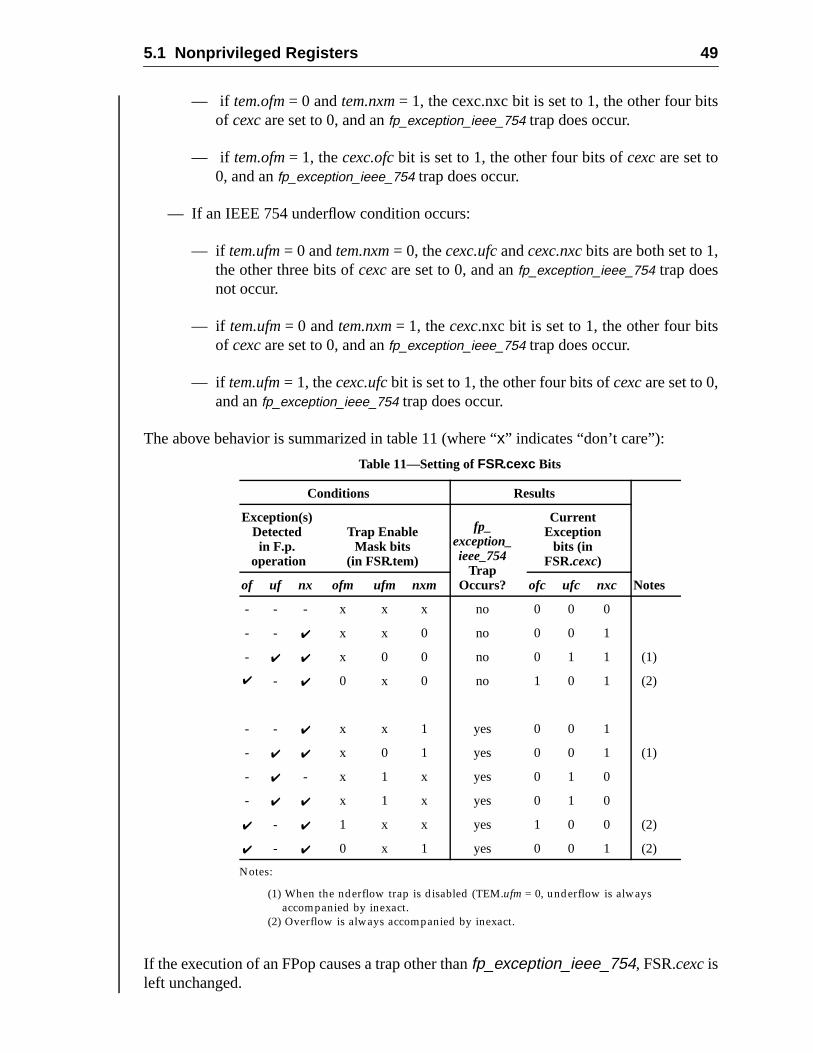
5.1 Nonprivileged Registers 49
ts
— if tem.ofm= 0 andtem.nxm= 1, the cexc.nxc bit is set to 1, the other four biof cexc are set to 0, and anfp_exception_ieee_754 trap does occur.— if tem.ofm= 1, thecexc.ofcbit is set to 1, the other four bits ofcexcare set to0, and anfp_exception_ieee_754 trap does occur.
— If an IEEE 754 underflow condition occurs:
— if tem.ufm= 0 andtem.nxm= 0, thecexc.ufcandcexc.nxcbits are both set to 1,the other three bits ofcexcare set to 0, and anfp_exception_ieee_754 trap doesnot occur.
— if tem.ufm= 0 andtem.nxm= 1, thecexc.nxc bit is set to 1, the other four bitsof cexc are set to 0, and anfp_exception_ieee_754 trap does occur.
— if tem.ufm= 1, thecexc.ufcbit is set to 1, the other four bits ofcexcare set to 0,and anfp_exception_ieee_754 trap does occur.
The above behavior is summarized in table 11 (where “x” indicates “don’t care”):
If the execution of an FPop causes a trap other thanfp_exception_ieee_754, FSR.cexcisleft unchanged.
Table 11—Setting ofFSR.cexc Bits
Conditions Results
Exception(s)Detectedin F.p.
operation
Trap EnableMask bits
(in FSR.tem)
fp_exception_ieee_754
TrapOccurs?
CurrentException
bits (inFSR.cexc)
of uf nx ofm ufm nxm ofc ufc nxc Notes
- - - x x x no 0 0 0
- - ✔ x x 0 no 0 0 1
- ✔ ✔ x 0 0 no 0 1 1 (1)
✔ - ✔ 0 x 0 no 1 0 1 (2)
- - ✔ x x 1 yes 0 0 1
- ✔ ✔ x 0 1 yes 0 0 1 (1)
- ✔ - x 1 x yes 0 1 0
- ✔ ✔ x 1 x yes 0 1 0
✔ - ✔ 1 x x yes 1 0 0 (2)
✔ - ✔ 0 x 1 yes 0 0 1 (2)
Notes:
(1) When the nderflow trap is disabled (TEM.ufm = 0, underflow is always
accompanied by inexact.
(2) Overflow is always accompanied by inexact.
50 5 Registers
lowing
agni-.
rmal-
cyep.ex-
ted
5.1.7.10 Floating-Point Exception Fields
The current and accrued exception fields and the trap enable mask assume the foldefinitions of the floating-point exception conditions (per IEEE Std 754-1985):
Figure 12—Trap Enable Mask (TEM) Fields of FSR
Figure 13—Accrued Exception Bits (aexc) Fields of FSR
Figure 14—Current Exception Bits (cexc) Fields of FSR
5.1.7.10.1 FSR_invalid ( nvc , nva)
An operand is improper for the operation to be performed. For example, 0.0÷ 0.0 and∞ –∞ are invalid. 1 = invalid operand(s), 0 = valid operand(s).
5.1.7.10.2 FSR_overflow ( ofc , ofa)
The result, rounded as if the exponent range were unbounded, would be larger in mtude than the destination format’s largest finite number. 1 = overflow, 0 = no overflow
5.1.7.10.3 FSR_underflow ( ufc , ufa)
The rounded result is inexact and would be smaller in magnitude than the smallest noized number in the indicated format. 1 = underflow, 0 = no underflow.
Underflow is never indicated when the correct unrounded result is zero. Otherwise:
If UFM = 0 : Underflow occurs if a nonzero result is tiny and a loss of accuraoccurs. Tininess may be detected before or after rounding (impl. d#55). Loss of accuracy may be either a denormalization loss or an inact result.
If UFM = 1 : Underflow occurs if a nonzero result is tiny. Tininess may be detecbefore or after rounding (impl. dep. #55).
5.1.7.10.4 FSR_division-by-zero ( dzc, dza)
X ÷ 0.0, where X is subnormal or normalized. Note that 0.0÷ 0.0 doesnot set thedzcordza bits. 1 = division by zero, 0 = no division by zero.
24 2327 26 25
NVM OFM UFM DZM NXM
6 59 8 7
nva ofa ufa dza nxa
1 04 3 2
nvc ofc ufc dzc nxc
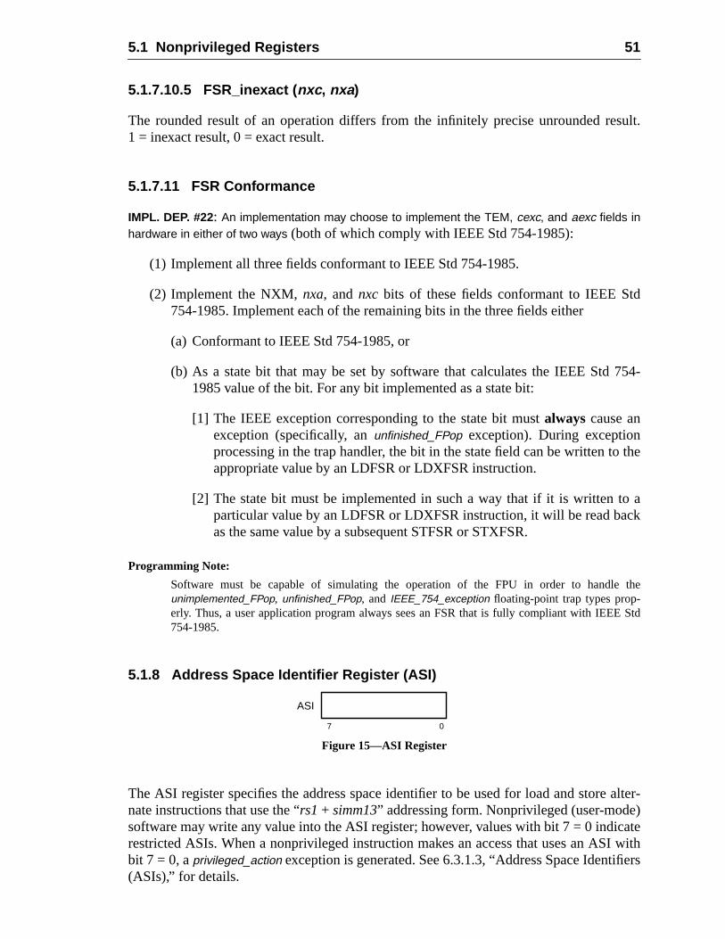
5.1 Nonprivileged Registers 51
sult.
d
754-
the
ack
the
Std
alter-)ateI withfiers
5.1.7.10.5 FSR_inexact ( nxc , nxa)
The rounded result of an operation differs from the infinitely precise unrounded re1 = inexact result, 0 = exact result.
5.1.7.11 FSR Conformance
IMPL. DEP. #22: An implementation may choose to implement the TEM, cexc, and aexc fields inhardware in either of two ways (both of which comply with IEEE Std 754-1985):
(1) Implement all three fields conformant to IEEE Std 754-1985.
(2) Implement the NXM,nxa, andnxc bits of these fields conformant to IEEE St754-1985. Implement each of the remaining bits in the three fields either
(a) Conformant to IEEE Std 754-1985, or
(b) As a state bit that may be set by software that calculates the IEEE Std1985 value of the bit. For any bit implemented as a state bit:
[1] The IEEE exception corresponding to the state bit mustalways cause anexception (specifically, anunfinished_FPop exception). During exceptionprocessing in the trap handler, the bit in the state field can be written toappropriate value by an LDFSR or LDXFSR instruction.
[2] The state bit must be implemented in such a way that if it is written toparticular value by an LDFSR or LDXFSR instruction, it will be read baas the same value by a subsequent STFSR or STXFSR.
Programming Note:
Software must be capable of simulating the operation of the FPU in order to handleunimplemented_FPop, unfinished_FPop, and IEEE_754_exception floating-point trap types prop-erly. Thus, a user application program always sees an FSR that is fully compliant with IEEE754-1985.
5.1.8 Address Space Identifier Register (ASI)
Figure 15—ASI Register
The ASI register specifies the address space identifier to be used for load and storenate instructions that use the “rs1+ simm13” addressing form. Nonprivileged (user-modesoftware may write any value into the ASI register; however, values with bit 7 = 0 indicrestricted ASIs. When a nonprivileged instruction makes an access that uses an ASbit 7 = 0, aprivileged_action exception is generated. See 6.3.1.3, “Address Space Identi(ASIs),” for details.
7 0
ASI
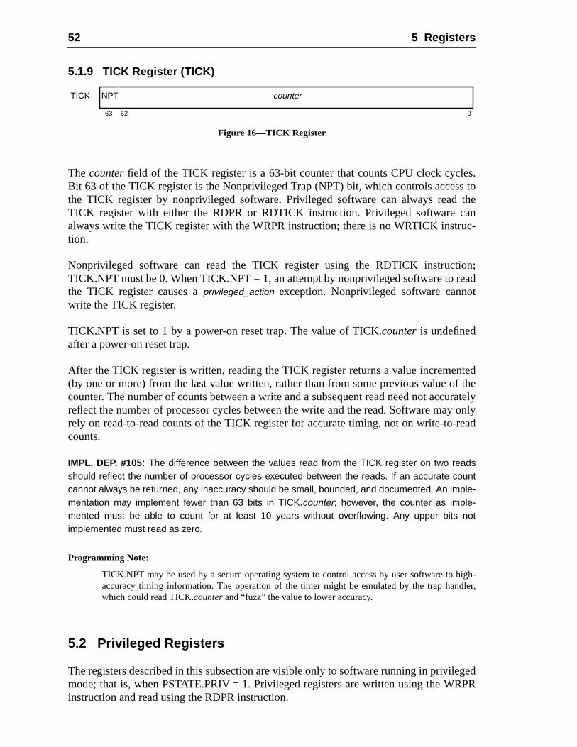
52 5 Registers
es.s to
theanc-
on;eadt
tedf theuratelyy onlyread
high-dler,
egedPR
5.1.9 TICK Register (TICK)
Figure 16—TICK Register
The counterfield of the TICK register is a 63-bit counter that counts CPU clock cyclBit 63 of the TICK register is the Nonprivileged Trap (NPT) bit, which controls accesthe TICK register by nonprivileged software. Privileged software can always readTICK register with either the RDPR or RDTICK instruction. Privileged software calways write the TICK register with the WRPR instruction; there is no WRTICK instrution.
Nonprivileged software can read the TICK register using the RDTICK instructiTICK.NPT must be 0. When TICK.NPT = 1, an attempt by nonprivileged software to rthe TICK register causes aprivileged_action exception. Nonprivileged software cannowrite the TICK register.
TICK.NPT is set to 1 by a power-on reset trap. The value of TICK.counteris undefinedafter a power-on reset trap.
After the TICK register is written, reading the TICK register returns a value incremen(by one or more) from the last value written, rather than from some previous value ocounter. The number of counts between a write and a subsequent read need not accreflect the number of processor cycles between the write and the read. Software marely on read-to-read counts of the TICK register for accurate timing, not on write-to-counts.
IMPL. DEP. #105: The difference between the values read from the TICK register on two readsshould reflect the number of processor cycles executed between the reads. If an accurate countcannot always be returned, any inaccuracy should be small, bounded, and documented. An imple-mentation may implement fewer than 63 bits in TICK.counter; however, the counter as imple-mented must be able to count for at least 10 years without overflowing. Any upper bits notimplemented must read as zero.
Programming Note:
TICK.NPT may be used by a secure operating system to control access by user software toaccuracy timing information. The operation of the timer might be emulated by the trap hanwhich could read TICK.counter and “fuzz” the value to lower accuracy.
5.2 Privileged Registers
The registers described in this subsection are visible only to software running in privilmode; that is, when PSTATE.PRIV = 1. Privileged registers are written using the WRinstruction and read using the RDPR instruction.
063 62
TICK NPT counter
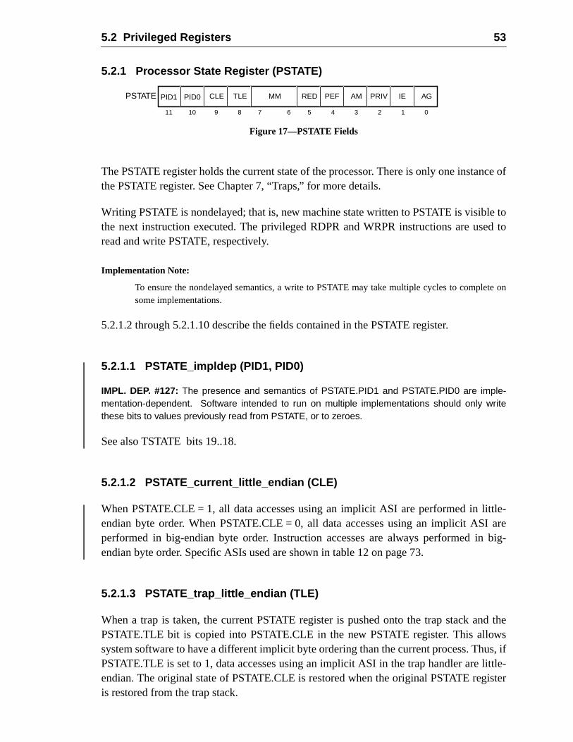
5.2 Privileged Registers 53
nce of
e toed to
te on
ttle-I are
big-
d thewsus, iflittle-ister
5.2.1 Processor State Register (PSTATE)
Figure 17—PSTATE Fields
The PSTATE register holds the current state of the processor. There is only one instathe PSTATE register. See Chapter 7, “Traps,” for more details.
Writing PSTATE is nondelayed; that is, new machine state written to PSTATE is visiblthe next instruction executed. The privileged RDPR and WRPR instructions are usread and write PSTATE, respectively.
Implementation Note:
To ensure the nondelayed semantics, a write to PSTATE may take multiple cycles to complesome implementations.
5.2.1.2 through 5.2.1.10 describe the fields contained in the PSTATE register.
5.2.1.1 PSTATE_impldep (PID1, PID0)
IMPL. DEP. #127: The presence and semantics of PSTATE.PID1 and PSTATE.PID0 are imple-mentation-dependent. Software intended to run on multiple implementations should only writethese bits to values previously read from PSTATE, or to zeroes.
See also TSTATE bits 19..18.
5.2.1.2 PSTATE_current_little_endian (CLE)
When PSTATE.CLE = 1, all data accesses using an implicit ASI are performed in liendian byte order. When PSTATE.CLE = 0, all data accesses using an implicit ASperformed in big-endian byte order. Instruction accesses are always performed inendian byte order. Specific ASIs used are shown in table 12 on page 73.
5.2.1.3 PSTATE_trap_little_endian (TLE)
When a trap is taken, the current PSTATE register is pushed onto the trap stack anPSTATE.TLE bit is copied into PSTATE.CLE in the new PSTATE register. This allosystem software to have a different implicit byte ordering than the current process. ThPSTATE.TLE is set to 1, data accesses using an implicit ASI in the trap handler areendian. The original state of PSTATE.CLE is restored when the original PSTATE regis restored from the trap stack.
4 0
PSTATE PEF AM PRIV IE AG
3 2 16 5
MM RED
7
TLECLE
9 8
PID0PID1
11 10
54 5 Registers
:
thetoreple-
set-dep.
andresetft-
of
recom-MPLfor theedi-
e toande the
high-stem.
5.2.1.4 PSTATE_mem_model (MM)
This 2-bit field determines the memory model in use by the processor. Its values are
An implementation must provide a memory model that allows programs conforming toTSO model to run correctly; that is, TSO or a stronger model. Whether the Partial SOrder (PSO) model or the Relaxed Memory Ordering (RMO) model is supported is immentation-dependent (impl. dep. #113).
The current memory model is determined by the value of PSTATE.MM. The effect ofting PSTATE.MM to an unsupported value is implementation-dependent (impl.#119).
5.2.1.5 PSTATE_RED_state (RED)
When PSTATE.RED is set to 1, the processor is operating in RED (Reset, Error,Debug) state. See 7.2.1, “RED_state.” The IU sets PSTATE.RED when any hardwareoccurs. It also sets PSTATE.RED when a trap is taken while TL = (MAXTL – 1). Soware can exit RED_state by one of two methods:
(1) Execute a DONE or RETRY instruction, which restores the stacked copyPSTATE and clears PSTATE.RED if it was 0 in the stacked copy.
(2) Write a 0 to PSTATE.RED with a WRPR instruction.
Programming Note:Changing PSTATE.RED may cause a change in address mapping on some systems. It ismended that writes of PSTATE.RED be placed in the delay slot of a JMPL; the target of this Jshould be in the new address mapping. The JMPL sets the nPC, which becomes the PCinstruction that folows the WRPR in its delay slot. The effect of the WRPR instruction is immate.
5.2.1.6 PSTATE_enable_floating-point (PEF)
When set to 1, this bit enables the floating-point unit, which allows privileged softwarmanage the FPU. For the floating-point unit to be usable, both PSTATE.PEFFPRS.FEF must be set. Otherwise, a floating-point instruction that tries to referencFPU will cause anfp_disabled trap.
5.2.1.7 PSTATE_address_mask (AM)
When PSTATE.AM = 1, both instruction and data addresses are interpreted as if theorder 32 bits were masked to zero before being presented to the MMU or memory syThirty-two-bit application software must run with this bit set.
Value Memory model
00 Total Store Order (TSO)
01 Partial Store Order (PSO)
10 Relaxed Memory Order (RMO)
11 —
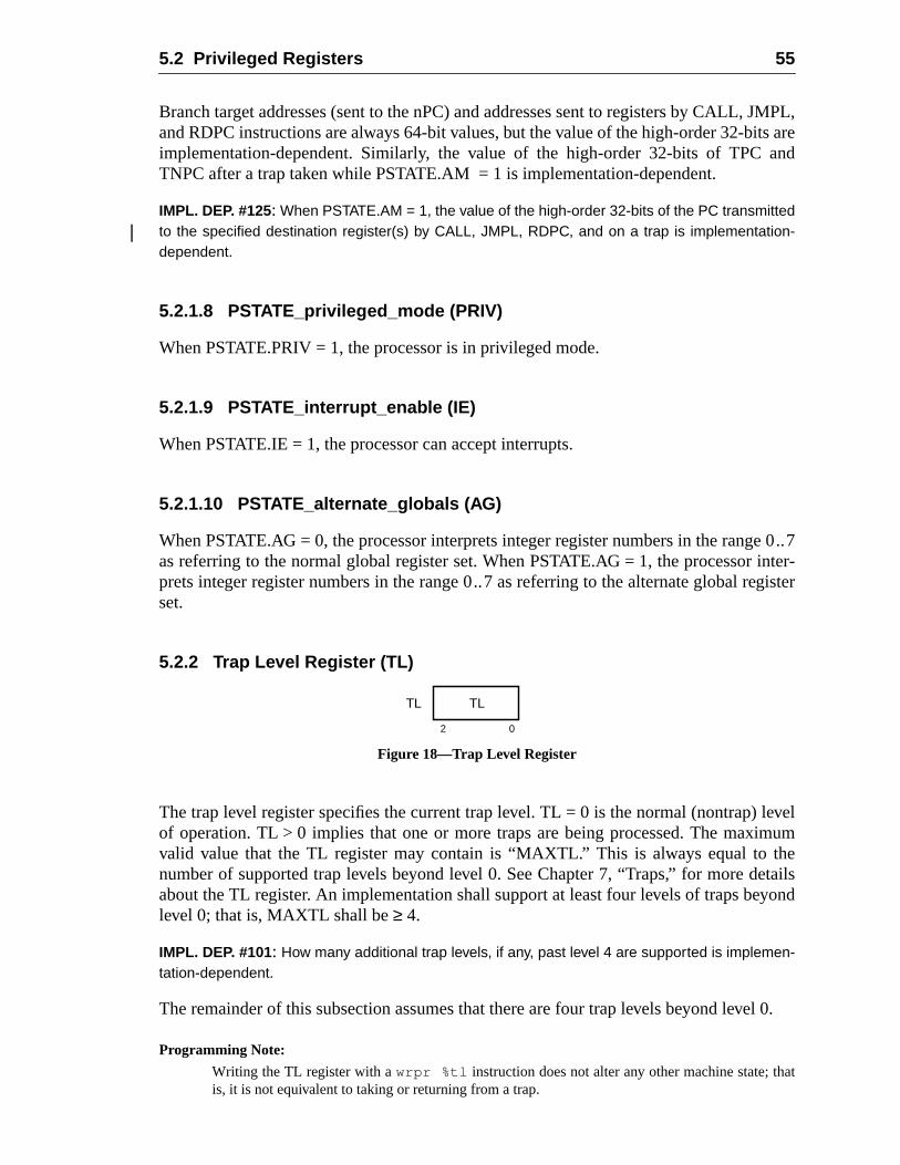
5.2 Privileged Registers 55
JMPL,ts areand
e 0..7inter-gister
levelmumheetailsyond
el 0.
at
Branch target addresses (sent to the nPC) and addresses sent to registers by CALL,and RDPC instructions are always 64-bit values, but the value of the high-order 32-biimplementation-dependent. Similarly, the value of the high-order 32-bits of TPCTNPC after a trap taken while PSTATE.AM = 1 is implementation-dependent.
IMPL. DEP. #125: When PSTATE.AM = 1, the value of the high-order 32-bits of the PC transmittedto the specified destination register(s) by CALL, JMPL, RDPC, and on a trap is implementation-dependent.
5.2.1.8 PSTATE_privileged_mode (PRIV)
When PSTATE.PRIV = 1, the processor is in privileged mode.
5.2.1.9 PSTATE_interrupt_enable (IE)
When PSTATE.IE = 1, the processor can accept interrupts.
5.2.1.10 PSTATE_alternate_globals (AG)
When PSTATE.AG = 0, the processor interprets integer register numbers in the rangas referring to the normal global register set. When PSTATE.AG = 1, the processorprets integer register numbers in the range 0..7 as referring to the alternate global reset.
5.2.2 Trap Level Register (TL)
Figure 18—Trap Level Register
The trap level register specifies the current trap level. TL = 0 is the normal (nontrap)of operation. TL > 0 implies that one or more traps are being processed. The maxivalid value that the TL register may contain is “MAXTL.” This is always equal to tnumber of supported trap levels beyond level 0. See Chapter 7, “Traps,” for more dabout the TL register. An implementation shall support at least four levels of traps belevel 0; that is, MAXTL shall be≥ 4.
IMPL. DEP. #101: How many additional trap levels, if any, past level 4 are supported is implemen-tation-dependent.
The remainder of this subsection assumes that there are four trap levels beyond lev
Programming Note:
Writing the TL register with awrpr %tl instruction does not alter any other machine state; this, it is not equivalent to taking or returning from a trap.
2 0
TL TL
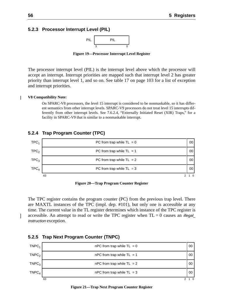
56 5 Registers
willreaterption
differ-ts dif-r a
hereanyter is
5.2.3 Processor Interrupt Level (PIL)
Figure 19—Processor Interrupt Level Register
The processor interrupt level (PIL) is the interrupt level above which the processoraccept an interrupt. Interrupt priorities are mapped such that interrupt level 2 has gpriority than interrupt level 1, and so on. See table 17 on page 103 for a list of exceand interrupt priorities.
V8 Compatibility Note:
On SPARC-V8 processors, the level 15 interrupt is considered to be nonmaskable, so it hasent semantics from other interrupt levels. SPARC-V9 processors do not treat level 15 interrupferently from other interrupt levels. See 7.6.2.4, “Externally Initiated Reset (XIR) Traps,” fofacility in SPARC-V9 that is similar to a nonmaskable interrupt.
5.2.4 Trap Program Counter (TPC)
Figure 20—Trap Program Counter Register
The TPC register contains the program counter (PC) from the previous trap level. Tare MAXTL instances of the TPC (impl. dep. #101), but only one is accessible attime. The current value in the TL register determines which instance of the TPC regisaccessible. An attempt to read or write the TPC register when TL = 0 causes anillegal_instruction exception.
5.2.5 Trap Next Program Counter (TNPC)
Figure 21—Trap Next Program Counter Register
3 0
PIL PIL
TPC1 PC from trap while TL = 0
2
00
63 1 0
TPC2 PC from trap while TL = 1 00
TPC3 PC from trap while TL = 2 00
TPC4 PC from trap while TL = 3 00
TNPC1 nPC from trap while TL = 0
2
00
63 1 0
TNPC2 nPC from trap while TL = 1 00
TNPC3 nPC from trap while TL = 2 00
TNPC4 nPC from trap while TL = 3 00
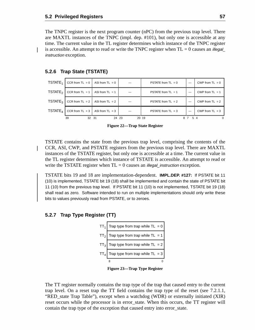
5.2 Privileged Registers 57
hereanyister
f theTL
lue inad or
rrent2.1.1,IR)r will
The TNPC register is the next program counter (nPC) from the previous trap level. Tare MAXTL instances of the TNPC (impl. dep. #101), but only one is accessible attime. The current value in the TL register determines which instance of the TNPC regis accessible. An attempt to read or write the TNPC register when TL = 0 causes anillegal_instruction exception.
5.2.6 Trap State (TSTATE)
Figure 22—Trap State Register
TSTATE contains the state from the previous trap level, comprising the contents oCCR, ASI, CWP, and PSTATE registers from the previous trap level. There are MAXinstances of the TSTATE register, but only one is accessible at a time. The current vathe TL register determines which instance of TSTATE is accessible. An attempt to rewrite the TSTATE register when TL = 0 causes anillegal_instruction exception.
TSTATE bits 19 and 18 are implementation-dependent.IMPL.DEP. #127: If PSTATE bit 11(10) is implemented, TSTATE bit 19 (18) shall be implemented and contain the state of PSTATE bit11 (10) from the previous trap level. If PSTATE bit 11 (10) is not implemented, TSTATE bit 19 (18)shall read as zero. Software intended to run on multiple implementations should only write thesebits to values previously read from PSTATE, or to zeroes.
5.2.7 Trap Type Register (TT)
Figure 23—Trap Type Register
The TT register normally contains the trap type of the trap that caused entry to the cutrap level. On a reset trap the TT field contains the trap type of the reset (see 7.“RED_state Trap Table”), except when a watchdog (WDR) or externally initiated (Xreset occurs while the processor is in error_state. When this occurs, the TT registecontain the trap type of the exception that caused entry into error_state.
39 0
TSTATE1 CCR from TL = 0 CWP from TL = 0ASI from TL = 0 PSTATE from TL = 0— —
432 31 24 23 20 8 7 519
TSTATE2 CCR from TL = 1 CWP from TL = 1ASI from TL = 1 PSTATE from TL = 1— —
TSTATE3 CCR from TL = 2 CWP from TL = 2ASI from TL = 2 PSTATE from TL = 2— —
TSTATE4 CCR from TL = 3 CWP from TL = 3ASI from TL = 3 PSTATE from TL = 3— —
TT1 Trap type from trap while TL = 0
8 0
TT2 Trap type from trap while TL = 1
TT3 Trap type from trap while TL = 2
TT4 Trap type from trap while TL = 3
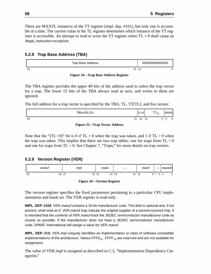
58 5 Registers
ssi-reg-e an
vectorare
s:
nL = 0rs.
ple-
Cat-
There are MAXTL instances of the TT register (impl. dep. #101), but only one is acceble at a time. The current value in the TL register determines which instance of the TTister is accessible. An attempt to read or write the TT register when TL = 0 shall causillegal_instruction exception.
5.2.8 Trap Base Address (TBA)
Figure 24—Trap Base Address Register
The TBA register provides the upper 49 bits of the address used to select the trapfor a trap. The lower 15 bits of the TBA always read as zero, and writes to themignored.
The full address for a trap vector is specified by the TBA, TL, TT[TL], and five zeroe
Figure 25—Trap Vector Address
Note that the “(TL>0)” bit is 0 if TL = 0 when the trap was taken, and 1 if TL > 0 whethe trap was taken. This implies that there are two trap tables: one for traps from Tand one for traps from TL > 0. See Chapter 7, “Traps,” for more details on trap vecto
5.2.9 Version Register (VER)
Figure 26—Version Register
The version register specifies the fixed parameters pertaining to a particular CPU immentation and mask set. The VER register is read-only.
IMPL. DEP. #104: VER.manuf contains a 16-bit manufacturer code. This field is optional and, if notpresent, shall read as 0. VER.manuf may indicate the original supplier of a second-sourced chip. Itis intended that the contents of VER.manuf track the JEDEC semiconductor manufacturer code asclosely as possible. If the manufacturer does not have a JEDEC semiconductor manufacturercode, SPARC International will assign a value for VER.manuf.
IMPL. DEP. #13: VER.impl uniquely identifies an implementation or class of software-compatibleimplementations of the architecture. Values FFF016..FFFF16 are reserved and are not available forassignment.
The value of VER.impl is assigned as described in C.3, “Implementation Dependencyegories.”
63 15 14 0
000000000000000Trap Base Address
63 15 14 0
TBA<63:15>
13 45
TL>0 TTTL 00000
63 48 47 24 23 16 15 8 7 05 432 31
maxwin—maxtl—maskimplmanuf
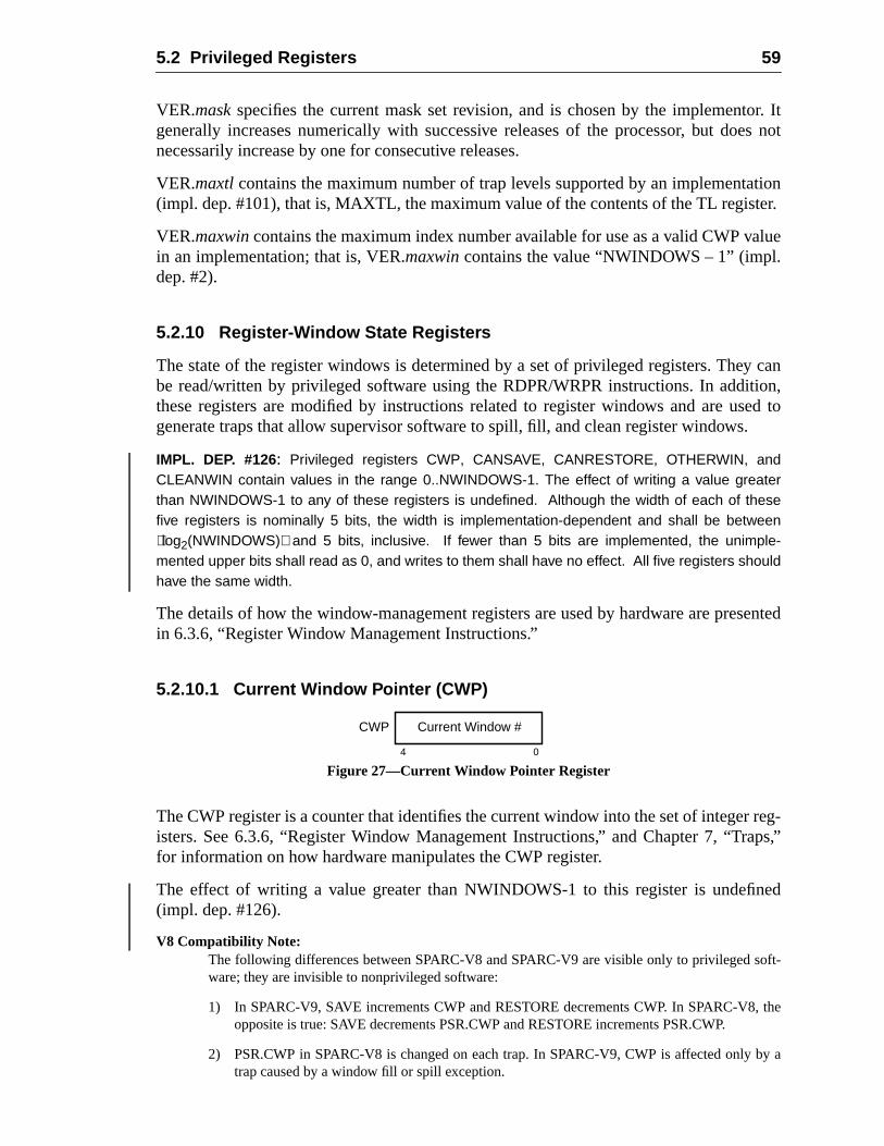
5.2 Privileged Registers 59
or. Ites not
tioner.
alue
y cantion,ed to.
sented
reg-aps,”
ned
oft-
, the
by a
VER.maskspecifies the current mask set revision, and is chosen by the implementgenerally increases numerically with successive releases of the processor, but donecessarily increase by one for consecutive releases.
VER.maxtlcontains the maximum number of trap levels supported by an implementa(impl. dep. #101), that is, MAXTL, the maximum value of the contents of the TL regist
VER.maxwincontains the maximum index number available for use as a valid CWP vin an implementation; that is, VER.maxwincontains the value “NWINDOWS – 1” (impl.dep. #2).
5.2.10 Register-Window State Registers
The state of the register windows is determined by a set of privileged registers. Thebe read/written by privileged software using the RDPR/WRPR instructions. In addithese registers are modified by instructions related to register windows and are usgenerate traps that allow supervisor software to spill, fill, and clean register windows
IMPL. DEP. #126: Privileged registers CWP, CANSAVE, CANRESTORE, OTHERWIN, andCLEANWIN contain values in the range 0..NWINDOWS-1. The effect of writing a value greaterthan NWINDOWS-1 to any of these registers is undefined. Although the width of each of thesefive registers is nominally 5 bits, the width is implementation-dependent and shall be betweenlog2(NWINDOWS) and 5 bits, inclusive. If fewer than 5 bits are implemented, the unimple-mented upper bits shall read as 0, and writes to them shall have no effect. All five registers shouldhave the same width.
The details of how the window-management registers are used by hardware are prein 6.3.6, “Register Window Management Instructions.”
5.2.10.1 Current Window Pointer (CWP)
Figure 27—Current Window Pointer Register
The CWP register is a counter that identifies the current window into the set of integeristers. See 6.3.6, “Register Window Management Instructions,” and Chapter 7, “Trfor information on how hardware manipulates the CWP register.
The effect of writing a value greater than NWINDOWS-1 to this register is undefi(impl. dep. #126).
V8 Compatibility Note:The following differences between SPARC-V8 and SPARC-V9 are visible only to privileged sware; they are invisible to nonprivileged software:
1) In SPARC-V9, SAVE increments CWP and RESTORE decrements CWP. In SPARC-V8opposite is true: SAVE decrements PSR.CWP and RESTORE increments PSR.CWP.
2) PSR.CWP in SPARC-V8 is changed on each trap. In SPARC-V9, CWP is affected onlytrap caused by a window fill or spill exception.
4 0
CWP Current Window #
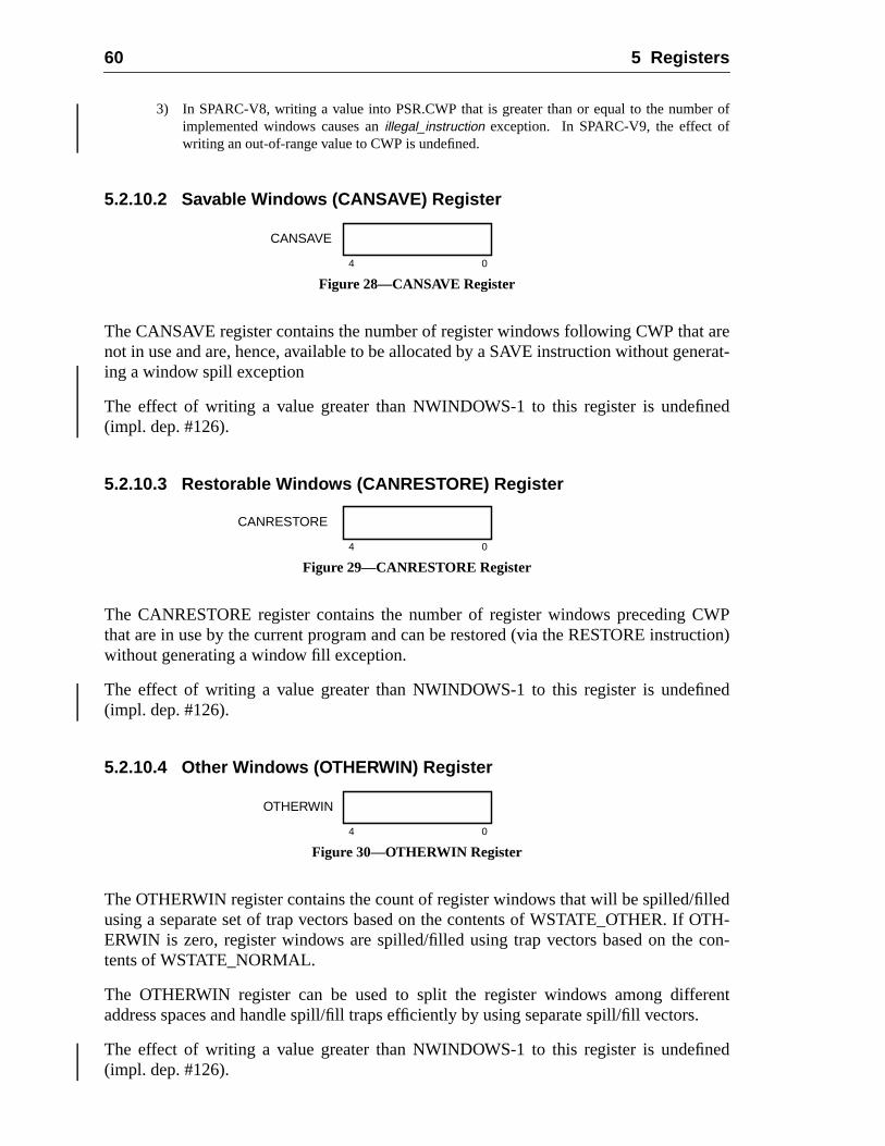
60 5 Registers
er of
areerat-
ned
WPction)
ned
ledOTH-con-
rents.
ned
3) In SPARC-V8, writing a value into PSR.CWP that is greater than or equal to the numbimplemented windows causes anillegal_instruction exception. In SPARC-V9, the effect ofwriting an out-of-range value to CWP is undefined.
5.2.10.2 Savable Windows (CANSAVE) Register
Figure 28—CANSAVE Register
The CANSAVE register contains the number of register windows following CWP thatnot in use and are, hence, available to be allocated by a SAVE instruction without gening a window spill exception
The effect of writing a value greater than NWINDOWS-1 to this register is undefi(impl. dep. #126).
5.2.10.3 Restorable Windows (CANRESTORE) Register
Figure 29—CANRESTORE Register
The CANRESTORE register contains the number of register windows preceding Cthat are in use by the current program and can be restored (via the RESTORE instruwithout generating a window fill exception.
The effect of writing a value greater than NWINDOWS-1 to this register is undefi(impl. dep. #126).
5.2.10.4 Other Windows (OTHERWIN) Register
Figure 30—OTHERWIN Register
The OTHERWIN register contains the count of register windows that will be spilled/filusing a separate set of trap vectors based on the contents of WSTATE_OTHER. IfERWIN is zero, register windows are spilled/filled using trap vectors based on thetents of WSTATE_NORMAL.
The OTHERWIN register can be used to split the register windows among diffeaddress spaces and handle spill/fill traps efficiently by using separate spill/fill vector
The effect of writing a value greater than NWINDOWS-1 to this register is undefi(impl. dep. #126).
4 0
CANSAVE
4 0
CANRESTORE
4 0
OTHERWIN
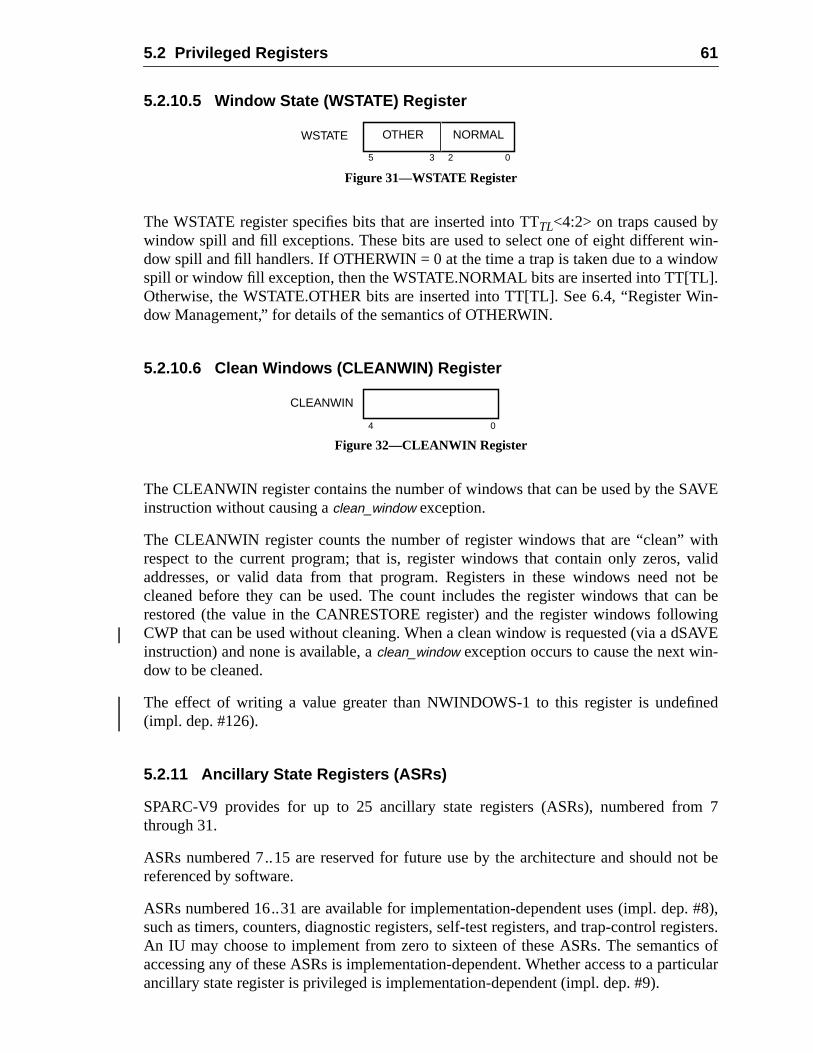
5.2 Privileged Registers 61
win-ow].in-
AVE
ithvalidot bean beingAVE-
ned
m 7
not be
. #8),isters.
cs ofrticular
5.2.10.5 Window State (WSTATE) Register
Figure 31—WSTATE Register
The WSTATE register specifies bits that are inserted into TTTL<4:2> on traps caused bywindow spill and fill exceptions. These bits are used to select one of eight differentdow spill and fill handlers. If OTHERWIN = 0 at the time a trap is taken due to a windspill or window fill exception, then the WSTATE.NORMAL bits are inserted into TT[TLOtherwise, the WSTATE.OTHER bits are inserted into TT[TL]. See 6.4, “Register Wdow Management,” for details of the semantics of OTHERWIN.
5.2.10.6 Clean Windows (CLEANWIN) Register
Figure 32—CLEANWIN Register
The CLEANWIN register contains the number of windows that can be used by the Sinstruction without causing aclean_window exception.
The CLEANWIN register counts the number of register windows that are “clean” wrespect to the current program; that is, register windows that contain only zeros,addresses, or valid data from that program. Registers in these windows need ncleaned before they can be used. The count includes the register windows that crestored (the value in the CANRESTORE register) and the register windows followCWP that can be used without cleaning. When a clean window is requested (via a dSinstruction) and none is available, aclean_window exception occurs to cause the next window to be cleaned.
The effect of writing a value greater than NWINDOWS-1 to this register is undefi(impl. dep. #126).
5.2.11 Ancillary State Registers (ASRs)
SPARC-V9 provides for up to 25 ancillary state registers (ASRs), numbered frothrough 31.
ASRs numbered 7..15 are reserved for future use by the architecture and shouldreferenced by software.
ASRs numbered 16..31 are available for implementation-dependent uses (impl. depsuch as timers, counters, diagnostic registers, self-test registers, and trap-control regAn IU may choose to implement from zero to sixteen of these ASRs. The semantiaccessing any of these ASRs is implementation-dependent. Whether access to a paancillary state register is privileged is implementation-dependent (impl. dep. #9).
WSTATE
05 3 2
OTHER NORMAL
4 0
CLEANWIN
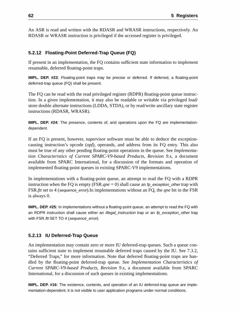
62 5 Registers
An
ent
truc-ad/
ister
ption-lso
n of
DPR
con-7.3.2,an-
f
An ASR is read and written with the RDASR and WRASR instructions, respectively.RDASR or WRASR instruction is privileged if the accessed register is privileged.
5.2.12 Floating-Point Deferred-Trap Queue (FQ)
If present in an implementation, the FQ contains sufficient state information to implemresumable, deferred floating-point traps.
IMPL. DEP. #23: Floating-point traps may be precise or deferred. If deferred, a floating-point
deferred-trap queue (FQ) shall be present.
The FQ can be read with the read privileged register (RDPR) floating-point queue instion. In a given implementation, it may also be readable or writable via privileged lostore double alternate instructions (LDDA, STDA), or by read/write ancillary state reginstructions (RDASR, WRASR).
IMPL. DEP. #24: The presence, contents of, and operations upon the FQ are implementation-
dependent.
If an FQ is present, however, supervisor software must be able to deduce the excecausing instruction’s opcode (opf), operands, and address from its FQ entry. This amust be true of any other pending floating-point operations in the queue. SeeImplementa-tion Characteristics of Current SPARC-V9-based Products, Revision 9.x, a documentavailable from SPARC International, for a discussion of the formats and operatioimplemented floating-point queues in existing SPARC-V9 implementations.
In implementations with a floating-point queue, an attempt to read the FQ with a Rinstruction when the FQ is empty (FSR.qne= 0) shall cause anfp_exception_other trap withFSR.ftt set to 4 (sequence_error).In implementations without an FQ, theqnebit in the FSRis always 0.
IMPL. DEP. #25: In implementations without a floating-point queue, an attempt to read the FQ with
an RDPR instruction shall cause either an illegal_instruction trap or an fp_exception_other trap
with FSR.ftt SET TO 4 (sequence_error).
5.2.13 IU Deferred-Trap Queue
An implementation may contain zero or more IU deferred-trap queues. Such a queuetains sufficient state to implement resumable deferred traps caused by the IU. See“Deferred Traps,” for more information. Note that deferred floating-point traps are hdled by the floating-point deferred-trap queue. SeeImplementation Characteristics oCurrent SPARC-V9-based Products, Revision 9.x, a document available from SPARCInternational, for a discussion of such queues in existing implementations.
IMPL. DEP. #16: The existence, contents, and operation of an IU deferred-trap queue are imple-
mentation-dependent; it is not visible to user application programs under normal conditions.
lled, orneral
andmem-ounter
es ita pre-ructionquest
raps,”
ramw, if) is
gram
addresstionsheir
execu-m-visi-uentialpli-
hown
6 Instructions
Instructions are accessed by the processor from memory and are executed, annutrapped. Instructions are encoded in four major formats and partitioned into eleven gecategories.
6.1 Instruction Execution
The instruction at the memory location specified by the program counter is fetchedthen executed. Instruction execution may change program-visible processor and/orory state. As a side-effect of its execution, new values are assigned to the program c(PC) and the next program counter (nPC).
An instruction may generate an exception if it encounters some condition that makimpossible to complete normal execution. Such an exception may in turn generatecise trap. Other events may also cause traps: an exception caused by a previous inst(a deferred trap), an interrupt or asynchronous error (a disrupting trap), or a reset re(a reset trap). If a trap occurs, control is vectored into a trap table. See Chapter 7, “Tfor a detailed description of exception and trap processing.
If a trap does not occur and the instruction is not a control transfer, the next progcounter (nPC) is copied into the PC and the nPC is incremented by 4 (ignoring overfloany). If the instruction is a control-transfer instruction, the next program counter (nPCcopied into the PC and the target address is written to nPC. Thus, the two procounters provide for a delayed-branch execution model.
For each instruction access and each normal data access, the IU appends an 8-bitspace identifier, or ASI, to the 64-bit memory address. Load/store alternate instruc(see 6.3.1.3, “Address Space Identifiers (ASIs),”) can provide an arbitrary ASI with tdata addresses, or use the ASI value currently contained in the ASI register.
Implementation Note:
The time required to execute an instruction is implementation-dependent, as is the degree oftion concurrency. In the absence of traps, an implementation should cause the same prograble register and memory state changes as if a program had executed according to the seqmodel implied in this document. See Chapter 7, “Traps,” for a definition of architectural comance in the presence of traps.
6.2 Instruction Formats
Instructions are encoded in four major 32-bit formats and several minor formats, as sin figures 33 and 34.
63
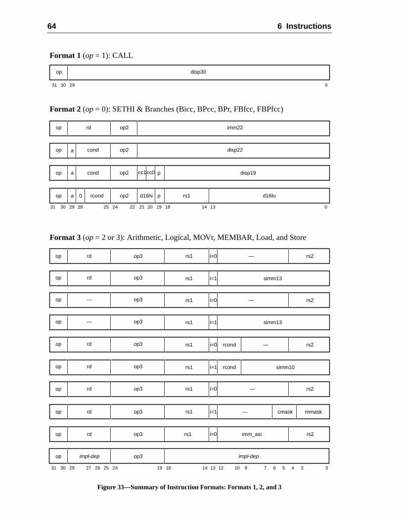
64 6 Instructions
Figure 33—Summary of Instruction Formats: Formats 1, 2, and 3
op3rdop rs1 i=1 mmask
31 030 29
disp30op
Format 1 (op= 1): CALL
Format 2 (op= 0): SETHI & Branches (Bicc, BPcc, BPr, FBfcc, FBPfcc)
Format 3 (op= 2 or 3): Arithmetic, Logical, MOVr, MEMBAR, Load, and Store
31 141924 18 13 12 5 4 02530 29
31 2224 21 02530 29
disp22op2condop a
op3rdop —rs1 i=0 rs2
op3rdop rs1 i=1 simm13
disp19op2condop a
d16loop2rcondop a
20 19 1828
0
cc1cc0 p
pd16hi
14 13
rs1
op3rdop rcondrs1 i=0 rs2
op3rdop rs1 i=1 simm10
10 9
rcond
—
—
op3rdop rs1 i=0 rs2—
op3—op —rs1 i=0 rs2
op3—op rs1 i=1 simm13
2627
imm22op2rdop
67
cmask
3
op rd op3 rs1 i=0 imm_asi rs2
op3impl-depop impl-dep
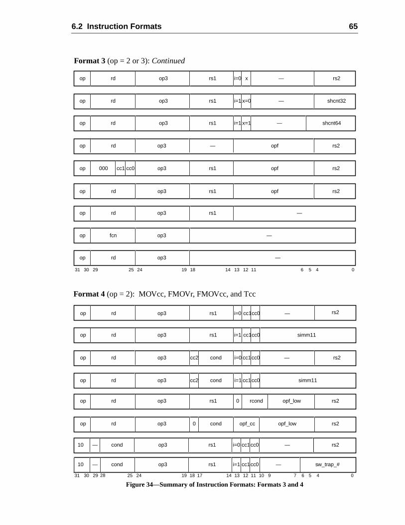
6.2 Instruction Formats 65
Figure 34—Summary of Instruction Formats: Formats 3 and 4
10 cond op3 rs1 i=1 —— cc1cc0 sw_trap_#
op3rdop rs1 i=0 rs2cc1cc0 —
Format 4 (op = 2): MOVcc, FMOVr, FMOVcc, and Tcc
op3rdop rs1 i=1 simm11
31 141924 18 13 12 5 4 02530 29 11 10 9
cc1cc0
7 6
op rd op3 cond opf_cc opf_low rs2
op rd op3 0 rcond opf_low rs2rs1
0
17
Format 3 (op = 2 or 3):Continued
31 24 02530 29 19 18
rdop op3 —
14 13 12 5 4
rs1 rs2i=0 x
rdop op3 —rs1 shcnt32i=1 x=0
rdop op3 —rs1 shcnt64i=1 x=1
6
op fcn op3 —
11
op3rdop rs1 —
rdop op3 —cond rs2i=0
rdop op3 cond simm11i=1
cc2
cc2
cc1
cc1
cc0
cc0
op3rdop —
op3rdop rs2opf—
op3rdop rs1 rs2opf
op op3 rs2000 rs1 opfcc1 cc0
10 cond op3 rs1 i=0 — rs2— cc1cc0
28
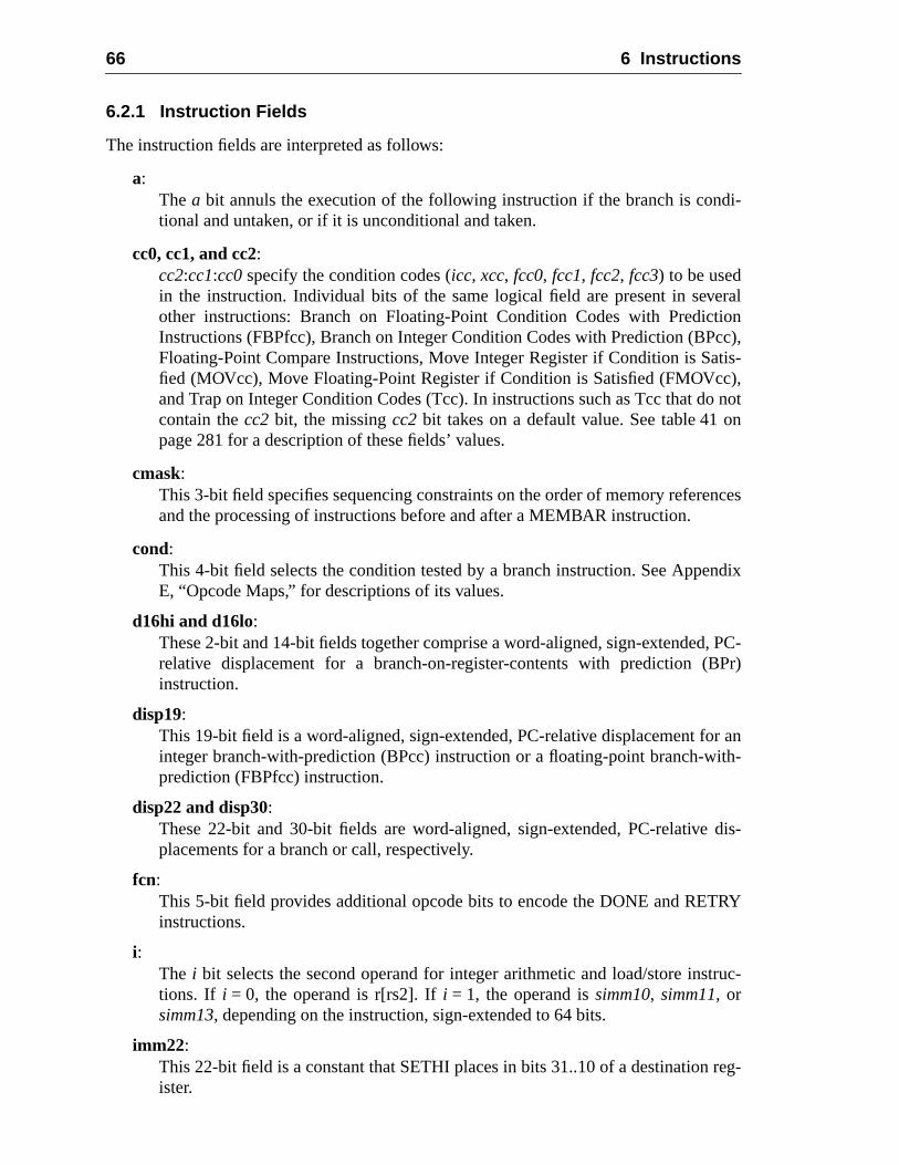
66 6 Instructions
di-
eralioncc),tis-),not
n
nces
ndix
, PC-Pr)
r anith-
dis-
RY
truc-
reg-
6.2.1 Instruction Fields
The instruction fields are interpreted as follows:
a:Thea bit annuls the execution of the following instruction if the branch is contional and untaken, or if it is unconditional and taken.
cc0, cc1, and cc2:cc2:cc1:cc0specify the condition codes (icc, xcc, fcc0, fcc1, fcc2, fcc3) to be usedin the instruction. Individual bits of the same logical field are present in sevother instructions: Branch on Floating-Point Condition Codes with PredictInstructions (FBPfcc), Branch on Integer Condition Codes with Prediction (BPFloating-Point Compare Instructions, Move Integer Register if Condition is Safied (MOVcc), Move Floating-Point Register if Condition is Satisfied (FMOVccand Trap on Integer Condition Codes (Tcc). In instructions such as Tcc that docontain thecc2 bit, the missingcc2 bit takes on a default value. See table 41 opage 281 for a description of these fields’ values.
cmask:This 3-bit field specifies sequencing constraints on the order of memory refereand the processing of instructions before and after a MEMBAR instruction.
cond:This 4-bit field selects the condition tested by a branch instruction. See AppeE, “Opcode Maps,” for descriptions of its values.
d16hi and d16lo:These 2-bit and 14-bit fields together comprise a word-aligned, sign-extendedrelative displacement for a branch-on-register-contents with prediction (Binstruction.
disp19:This 19-bit field is a word-aligned, sign-extended, PC-relative displacement fointeger branch-with-prediction (BPcc) instruction or a floating-point branch-wprediction (FBPfcc) instruction.
disp22 and disp30:These 22-bit and 30-bit fields are word-aligned, sign-extended, PC-relativeplacements for a branch or call, respectively.
fcn:This 5-bit field provides additional opcode bits to encode the DONE and RETinstructions.
i:The i bit selects the second operand for integer arithmetic and load/store instions. If i = 0, the operand is r[rs2]. Ifi = 1, the operand issimm10, simm11, orsimm13, depending on the instruction, sign-extended to 64 bits.
imm22:This 22-bit field is a constant that SETHI places in bits 31..10 of a destinationister.
6.2 Instruction Formats 67
rnate
for
efore
truc-
.
ruc-s.
sterof
fol-
d onntsip-
imm_asi:This 8-bit field is the address space identifier in instructions that access altespace.
impl-dep:The meaning of these fields is completely implementation-dependentIMPDEP1 and IMPDEP2 instructions.
mmask:This 4-bit field imposes order constraints on memory references appearing band after a MEMBAR instruction.
op and op2:These 2- and 3-bit fields encode the three major formats and the Format 2 instions. See Appendix E, “Opcode Maps,” for descriptions of their values.
op3:This 6-bit field (together with one bit fromop) encodes the Format 3 instructionsSee Appendix E, “Opcode Maps,” for descriptions of its values.
opf:This 9-bit field encodes the operation for a floating-point operate (FPop) insttion. See Appendix E, “Opcode Maps,” for possible values and their meaning
opf_cc:Specifies the condition codes to be used in FMOVcc instructions. Seecc0, cc1,and cc2 above for details.
opf_low:This 6-bit field encodes the specific operation for a Move Floating-Point Regiif Condition is satisfied (FMOVcc) or Move Floating-Point register if contentsinteger register match condition (FMOVr) instruction.
p:This 1-bit field encodes static prediction for BPcc and FBPfcc instructions, aslows:
rcond:This 3-bit field selects the register-contents condition to test for a move baseregister contents (MOVr or FMOVr) instruction or a branch on register contewith prediction (BPr) instruction. See Appendix E, “Opcode Maps,” for descrtions of its values.
rd:This 5-bit field is the address of the destination (or source)r or f register(s) for aload, arithmetic, or store instruction.
rs1:This 5-bit field is the address of the firstr or f register(s) source operand.
p Branch prediction
0 Predict branch will not be taken
1 Predict branch will be taken
68 6 Instructions
d as
d as
d astore
for a
rs2:This 5-bit field is the address of the secondr or f register(s) source operand withi = 0.
shcnt32:This 5-bit field provides the shift count for 32-bit shift instructions.
shcnt64:This 6-bit field provides the shift count for 64-bit shift instructions.
simm10:This 10-bit field is an immediate value that is sign-extended to 64 bits and usethe second ALU operand for a MOVr instruction wheni = 1.
simm11:This 11-bit field is an immediate value that is sign-extended to 64 bits and usethe second ALU operand for a MOVcc instruction wheni = 1.
simm13:This 13-bit field is an immediate value that is sign-extended to 64 bits and usethe second ALU operand for an integer arithmetic instruction or for a load/sinstruction wheni = 1.
sw_trap#:This 7-bit field is an immediate value that is used as the second ALU operandTrap on Condition Code instruction.
x:Thex bit selects whether a 32- or 64-bit shift will be performed..
6.3 Instruction Categories
SPARC-V9 instructions can be grouped into the following categories:
— Memory access
— Memory synchronization
— Integer arithmetic
— Control transfer (CTI)
— Conditional moves
— Register window management
— State register access
— Privileged register access
— Floating-point operate
— Implementation-dependent
— Reserved
6.3 Instruction Categories 69
re thewap
ye infor-
des-ed-desti-
sed
mem-
the
bit),word,cesses bytes.
can
deewordgned on
not
t not
Each of these categories is further described in the following subsections.
6.3.1 Memory Access Instructions
Load, Store, Prefetch, Load Store Unsigned Byte, Swap, and Compare and Swap aonly instructions that access memory. All of the instructions except Compare and Suse either twor registers or anr register andsimm13to calculate a 64-bit byte memoryaddress. Compare and Swap uses a singler register to specify a 64-bit byte memoraddress. To this 64-bit address, the IU appends an ASI that encodes address spacmation.
The destination field of a memory reference instruction specifies ther or f register(s) thatsupply the data for a store or receive the data from a load or LDSTUB. For SWAP, thetination register identifies ther register to be exchanged atomically with the calculatmemory location. For Compare and Swap, anr register is specified whose value is compared with the value in memory at the computed address. If the values are equal, thenation field specifies ther register that is to be exchanged atomically with the addresmemory location. If the values are unequal, the destination field specifies ther register thatis to receive the value at the addressed memory location; in this case, the addressedory location remains unchanged.
The destination field of a PREFETCH instruction is used to encode the type ofprefetch.
Integer load and store instructions support byte (8-bit), halfword (16-bit), word (32-and doubleword (64-bit) accesses. Floating-point load and store instructions supportdoubleword, and quadword memory accesses. LDSTUB accesses bytes, SWAP acwords, and CAS accesses words or doublewords. PREFETCH accesses at least 64
Programming Note:By settingi = 1 andrs1= 0, any location in the lowest or highest 4K bytes of an address spacebe accessed without using a register to hold part of the address.
6.3.1.1 Memory Alignment Restrictions
Halfword accesses shall bealigned on 2-byte boundaries, word accesses (which incluinstruction fetches) shall be aligned on 4-byte boundaries, extended word and doublaccesses shall be aligned on 8-byte boundaries, and quadword accesses shall be ali16-byte boundaries, with the following exceptions.
An improperly aligned address in a load, store, or load-store instruction causes amem_address_not_aligned exception to occur, except:
— An LDDF or LDDFA instruction accessing an address that is word-aligned butdoubleword-aligned may cause anLDDF_mem_address_not_aligned exception, ormay complete the operation in hardware (impl. dep. #109).
— An STDF or STDFA instruction accessing an address that is word-aligned budoubleword-aligned may cause anSTDF_mem_address_not_aligned exception ormay complete the operation in hardware (impl. dep. #110).
70 6 Instructions
not
t not
r datas. It is, “Pro-
nt; aconven-
little-
cantst sig-
cantleast
ightat thessed
big-n cor-s + 4
— An LDQF or LDQFA instruction accessing an address that is word-aligned butquadword-aligned may cause anLDQF_mem_address_not_aligned exception or maycomplete the operation in hardware (impl. dep. #111).
— An STQF or STQFA instruction accessing an address that is word-aligned buquadword aligned may cause anSTQF_mem_address_not_aligned exception or maycomplete the operation in hardware (impl. dep. #112).
6.3.1.2 Addressing Conventions
SPARC-V9 uses big-endian byte order for all instruction accesses and, by default, foaccesses. It is possible to access data in little-endian format by using selected ASIalso possible to change the default byte order for implicit data accesses. See 5.2.1cessor State Register (PSTATE),” for more information.1
6.3.1.2.1 Big-Endian Addressing Convention
Within a multiple-byte integer, the byte with the smallest address is the most significabyte’s significance decreases as its address increases. The big-endian addressingtions are illustrated in figure 35 and defined as follows:
byte:
A load/store byte instruction accesses the addressed byte in both big- andendian modes.
halfword :
For a load/store halfword instruction, two bytes are accessed. The most signifibyte (bits 15..8) is accessed at the address specified in the instruction; the leanificant byte (bits 7..0) is accessed at the address + 1.
word:
For a load/store word instruction, four bytes are accessed. The most signifibyte (bits 31..24) is accessed at the address specified in the instruction; thesignificant byte (bits 7..0) is accessed at the address + 3.
doubleword or extended word:
For a load/store extended or floating-point load/store double instruction, ebytes are accessed. The most significant byte (bits 63..56) is accessedaddress specified in the instruction; the least significant byte (bits 7..0) is acceat the address + 7.
For the deprecated integer load/store double instructions (LDD/STD), twoendian words are accessed. The word at the address specified in the instructioresponds to the even register specified in the instruction; the word at addrescorresponds to the following odd-numbered register.
1. See Cohen, D., “On Holy Wars and a Plea for Peace,”Computer 14:10 (October 1981), pp. 48-54.
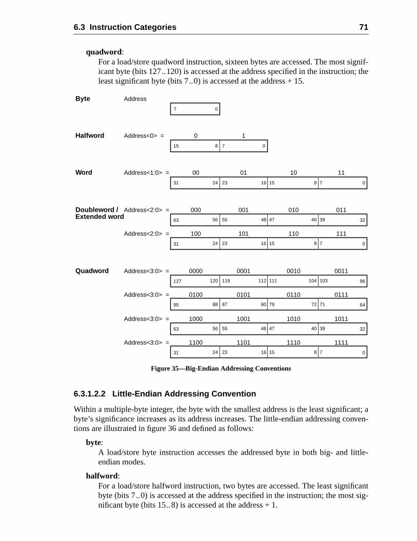
6.3 Instruction Categories 71
ignif-n; the
nt; aonven-
little-
ficantst sig-
quadword:For a load/store quadword instruction, sixteen bytes are accessed. The most sicant byte (bits 127..120) is accessed at the address specified in the instructioleast significant byte (bits 7..0) is accessed at the address + 15.
Figure 35—Big-Endian Addressing Conventions
6.3.1.2.2 Little-Endian Addressing Convention
Within a multiple-byte integer, the byte with the smallest address is the least significabyte’s significance increases as its address increases. The little-endian addressing ctions are illustrated in figure 36 and defined as follows:
byte:A load/store byte instruction accesses the addressed byte in both big- andendian modes.
halfword :For a load/store halfword instruction, two bytes are accessed. The least signibyte (bits 7..0) is accessed at the address specified in the instruction; the monificant byte (bits 15..8) is accessed at the address + 1.
Byte7 0
Halfword15 0
Word31 0
Doubleword /63 32
31 0
78
15 78162324
47 3940485556
15 78162324
0 1
00 01 10 11
Address
Address<0> =
Address<1:0> =
Address<2:0> =
Address<2:0> =
000 001 010 011
100 101 110 111
Quadword127 96
95 64
111 103104112119120
79 7172808788
Address<3:0> =
Address<3:0> =
0000 0001 0010 0011
0100 0101 0110 0111
63 32
31 0
47 3940485556
15 78162324
Address<3:0> =
Address<3:0> =
1000 1001 1010 1011
1100 1101 1110 1111
Extended word
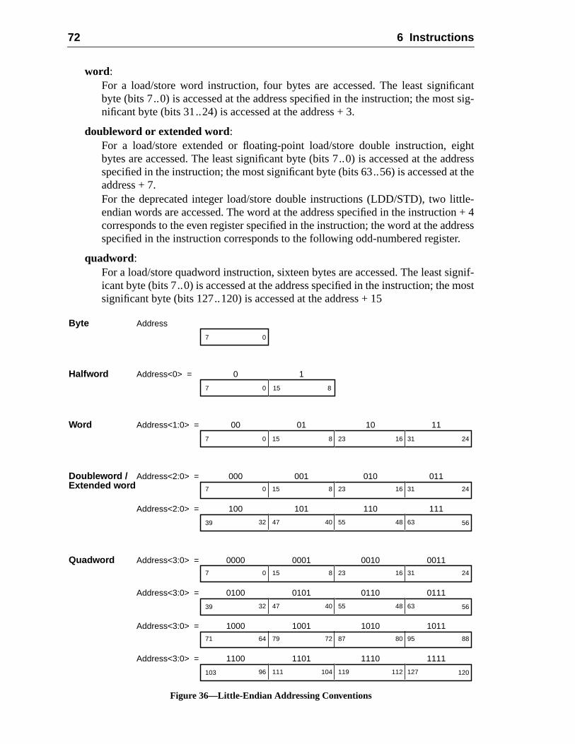
72 6 Instructions
cantst sig-
ightddresst the
ttle-on + 4dressr.
signif-most
word:For a load/store word instruction, four bytes are accessed. The least signifibyte (bits 7..0) is accessed at the address specified in the instruction; the monificant byte (bits 31..24) is accessed at the address + 3.
doubleword or extended word:For a load/store extended or floating-point load/store double instruction, ebytes are accessed. The least significant byte (bits 7..0) is accessed at the aspecified in the instruction; the most significant byte (bits 63..56) is accessed aaddress + 7.For the deprecated integer load/store double instructions (LDD/STD), two liendian words are accessed. The word at the address specified in the instructicorresponds to the even register specified in the instruction; the word at the adspecified in the instruction corresponds to the following odd-numbered registe
quadword:For a load/store quadword instruction, sixteen bytes are accessed. The leasticant byte (bits 7..0) is accessed at the address specified in the instruction; thesignificant byte (bits 127..120) is accessed at the address + 15
Figure 36—Little-Endian Addressing Conventions
Byte7 0
Halfword7 8
Word7 24
Doubleword /
150
23 31168150
0 1
00 01 10 11
Address
Address<0> =
Address<1:0> =
Address<2:0> =
Address<2:0> =
000 001 010 011
100 101 110 111
Quadword Address<3:0> =
Address<3:0> =
0000 0001 0010 0011
0100 0101 0110 0111
Address<3:0> =
Address<3:0> =
1000 1001 1010 1011
1100 1101 1110 1111
39 5655 6348404732
7 2423 31168150
39 5655 6348404732
7 2423 31168150
103 120119 12711210411196
71 8887 9580727964
Extended word
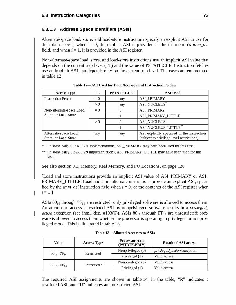
6.3 Instruction Categories 73
e for
e thatcheserated
I_ci-n
m.
npriv-
s a
6.3.1.3 Address Space Identifiers (ASIs)
Alternate-space load, store, and load-store instructions specify an explicit ASI to ustheir data access; wheni = 0, the explicit ASI is provided in the instruction’simm_asifield, and wheni = 1, it is provided in the ASI register.
Non-alternate-space load, store, and load-store instructions use an implicit ASI valudepends on the current trap level (TL) and the value of PSTATE.CLE. Instruction fetuse an implicit ASI that depends only on the current trap level. The cases are enumin table 12.
* On some early SPARC V9 implementations, ASI_PRIMARY may have been used for this case.
** On some early SPARC V9 implementations, ASI_PRIMARY_LITTLE may have been used for thiscase.
See also section 8.3, Memory, Real Memory, and I/O Locations, on page 120.
[Load and store instructions provide an implicit ASI value of ASI_PRIMARY or ASPRIMARY_LITTLE. Load and store alternate instructions provide an explicit ASI, spefied by theimm_asiinstruction field wheni = 0, or the contents of the ASI register whei = 1.]
ASIs 0016 through 7F16 are restricted; only privileged software is allowed to access theAn attempt to access a restricted ASI by nonprivileged software results in aprivileged_action exception (see impl. dep. #103(6)). ASIs 8016 through FF16 are unrestricted; soft-ware is allowed to access them whether the processor is operating in privileged or noileged mode. This is illustrated in table 13.
The required ASI assignments are shown in table 14. In the table, “R” indicaterestricted ASI, and “U” indicates an unrestricted ASI.
Table 12—ASI Used for Data Accesses and Instruction Fetches
Access Type TL PSTATE.CLE ASI Used
Instruction Fetch = 0 any ASI_PRIMARY
> 0 any ASI_NUCLEUS*
Non-alternate-space Load,Store, or Load-Store
= 0 0 ASI_PRIMARY
1 ASI_PRIMARY_LITTLE
> 0 0 ASI_NUCLEUS*
1 ASI_NUCLEUS_LITTLE**
Alternate-space Load,Store, or Load-Store
any any ASI explicitly specified in the instruction(subject to privilege-level restrictions)
Table 13—Allowed Accesses to ASIs
Value Access Type Processor state(PSTATE.PRIV) Result of ASI access
0016..7F16 RestrictedNonprivileged (0) privileged_action exception
Privileged (1) Valid access
8016..FF16 UnrestrictedNonprivileged (0) Valid access
Privileged (1) Valid access
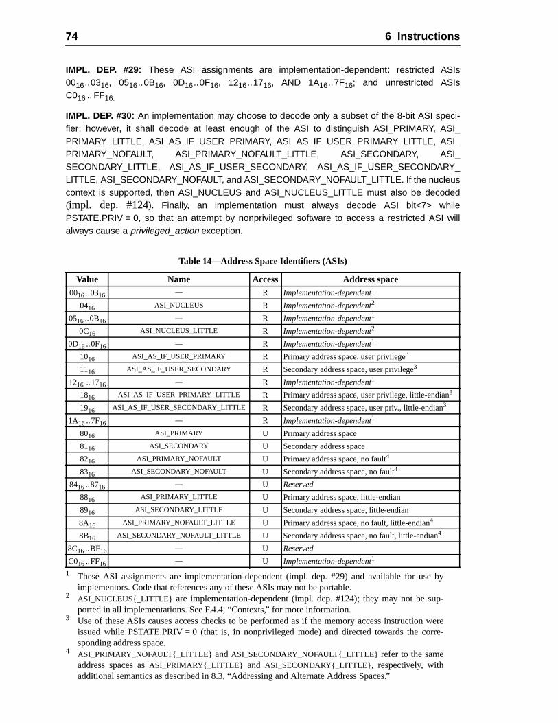
74 6 Instructions
by
ere-
IMPL. DEP. #29: These ASI assignments are implementation-dependent: restricted ASIs0016..0316, 0516..0B16, 0D16..0F16, 1216..1716, AND 1A16..7F16; and unrestricted ASIsC016 .. FF16.
IMPL. DEP. #30: An implementation may choose to decode only a subset of the 8-bit ASI speci-fier; however, it shall decode at least enough of the ASI to distinguish ASI_PRIMARY, ASI_PRIMARY_LITTLE, ASI_AS_IF_USER_PRIMARY, ASI_AS_IF_USER_PRIMARY_LITTLE, ASI_PRIMARY_NOFAULT, ASI_PRIMARY_NOFAULT_LITTLE, ASI_SECONDARY, ASI_SECONDARY_LITTLE, ASI_AS_IF_USER_SECONDARY, ASI_AS_IF_USER_SECONDARY_LITTLE, ASI_SECONDARY_NOFAULT, and ASI_SECONDARY_NOFAULT_LITTLE. If the nucleuscontext is supported, then ASI_NUCLEUS and ASI_NUCLEUS_LITTLE must also be decoded(impl. dep. #124). Finally, an implementation must always decode ASI bit<7> whilePSTATE.PRIV = 0, so that an attempt by nonprivileged software to access a restricted ASI willalways cause a privileged_action exception.
1 These ASI assignments are implementation-dependent (impl. dep. #29) and available for useimplementors. Code that references any of these ASIs may not be portable.
2 ASI_NUCLEUS{_LITTLE} are implementation-dependent (impl. dep. #124); they may not be sup-ported in all implementations. See F.4.4, “Contexts,” for more information.
3 Use of these ASIs causes access checks to be performed as if the memory access instruction wissued while PSTATE.PRIV = 0 (that is, in nonprivileged mode) and directed towards the corresponding address space.
4 ASI_PRIMARY_NOFAULT{_LITTLE} andASI_SECONDARY_NOFAULT{_LITTLE} refer to the sameaddress spaces asASI_PRIMARY{_LITTLE} and ASI_SECONDARY{_LITTLE}, respectively, withadditional semantics as described in 8.3, “Addressing and Alternate Address Spaces.”
Table 14—Address Space Identifiers (ASIs)
Value Name Access Address space0016..0316 — R Implementation-dependent1
0416 ASI_NUCLEUS R Implementation-dependent2
0516..0B16 — R Implementation-dependent1
0C16 ASI_NUCLEUS_LITTLE R Implementation-dependent2
0D16..0F16 — R Implementation-dependent1
1016 ASI_AS_IF_USER_PRIMARY R Primary address space, user privilege3
1116 ASI_AS_IF_USER_SECONDARY R Secondary address space, user privilege3
1216 ..1716 — R Implementation-dependent1
1816 ASI_AS_IF_USER_PRIMARY_LITTLE R Primary address space, user privilege, little-endian3
1916 ASI_AS_IF_USER_SECONDARY_LITTLE R Secondary address space, user priv., little-endian3
1A16..7F16 — R Implementation-dependent1
8016 ASI_PRIMARY U Primary address space
8116 ASI_SECONDARY U Secondary address space
8216 ASI_PRIMARY_NOFAULT U Primary address space, no fault4
8316 ASI_SECONDARY_NOFAULT U Secondary address space, no fault4
8416..8716 — U Reserved
8816 ASI_PRIMARY_LITTLE U Primary address space, little-endian
8916 ASI_SECONDARY_LITTLE U Secondary address space, little-endian
8A16 ASI_PRIMARY_NOFAULT_LITTLE U Primary address space, no fault, little-endian4
8B16 ASI_SECONDARY_NOFAULT_LITTLE U Secondary address space, no fault, little-endian4
8C16..BF16 — U Reserved
C016..FF16 — U Implementation-dependent1
6.3 Instruction Categories 75
harednt at alluctionssharedue as to a
theder-BARs
oded
per-
thatesult
itionecialusingtruc-
of
6.3.1.4 Separate Instruction Memory
A SPARC-V9 implementation may choose to place instruction and data in the same saddress space and use hardware to keep the data and instruction memory consistetimes. It may also choose to overload independent address spaces for data and instrand allow them to become inconsistent when data writes are made to addresseswith the instruction space. A program containing such self-modifying code must issFLUSH instruction or appropriate calls to system software to bring the address spaceconsistent state. See H.1.6, “Self-Modifying Code,” for more information.
6.3.2 Memory Synchronization Instructions
Two forms of memory barrier (MEMBAR) instructions allow programs to manageorder and completion of memory references. Ordering MEMBARs induce a partial oring between sets of loads and stores and future loads and stores. Sequencing MEMexert explicit control over completion of loads and stores. Both barrier forms are encin a single instruction, with sub-functions bit-encoded in an immediate field.
V8 Compatibility Note:
The deprecated STBAR instruction is a subcase of the MEMBAR instruction; it is identical in oation to the STBAR instruction of SPARC-V8, and is included only for compatibility.
6.3.3 Integer Arithmetic Instructions
The integer arithmetic instructions are generally triadic-register-address instructionscompute a result which is a function of two source operands. They either write the rinto the destination registerr[rd] or discard it. One of the source operands is always r[rs1].The other source operand depends on thei bit in the instruction; ifi = 0, the operand isr[rs2]; if i = 1, the operand is the constantsimm10, simm11, or simm13sign-extended to64 bits.
Note that the value ofr[0] always reads as zero, and writes to it are ignored.
6.3.3.1 Setting Condition Codes
Most integer arithmetic instructions have two versions; one sets the integer condcodes (icc andxcc) as a side effect; the other does not affect the condition codes. A spcomparison instruction for integer values is not needed, since it is easily synthesizedthe “subtract and set condition codes” (SUBcc) instruction. See G.3, “Synthetic Instions,” for details.
6.3.3.2 Shift Instructions
Shift instructions shift anr register left or right by a constant or variable amount. Nonethe shift instructions changes the condition codes.
76 6 Instructions
-thepri-
,-
is the, or ift the
useer-
ntergramf theare
n iser
thetruc-
6.3.3.3 Set High 22 Bits of Low Word
The “set high 22 bits of low word of anr register” instruction (SETHI) writes a 22-bit constant from the instruction into bits 31 through 10 of the destination register. It clearslow-order 10 bits and high-order 32 bits, and does not affect the condition codes. Itsmary use is to construct constants in registers.
6.3.3.4 Integer Multiply/Divide
The integer multiply instruction performs a 64× 64 → 64-bit operation; the integer divideinstructions perform 64÷ 64 → 64-bit operations. For compatibility with SPARC-V832 × 32 → 64-bit multiply instructions, 64÷ 32 → 32-bit divide instructions, and the multiply step instruction are provided. Division by zero causes adivision_by_zero exception.
6.3.3.5 Tagged Add/Subtract
The tagged add/subtract instructions assume tagged-format data, in which the tagtwo low-order bits of each operand. If either of the two operands has a nonzero tag32-bit arithmetic overflow occurs, tag overflow is detected. TADDcc and TSUBcc seCCR.icc.V bit if tag overflow occurs; they set the CCR.xcc.V bit if 64-bit arithmetic over-flow occurs. The trapping versions (TADDccTV, TSUBccTV) of these instructions caa tag_overflow trap if tag overflow occurs. If 64-bit arithmetic overflow occurs but tag ovflow does not, TADDccTV and TSUBccTV set the CCR.xcc.V bit but do not trap.
6.3.4 Control-Transfer Instructions (CTIs)
These are the basic control-transfer instruction types:
— Conditional branch (Bicc, BPcc, BPr, FBfcc, FBPfcc)
— Unconditional Branch
— Call and Link (CALL)
— Jump and Link (JMPL, RETURN)
— Return from trap (DONE, RETRY)
— Trap (Tcc)
A control-transfer instruction functions by changing the value of the next program cou(nPC) or by changing the value of both the program counter (PC) and the next procounter (nPC). When only the next program counter, nPC, is changed, the effect otransfer of control is delayed by one instruction. Most control transfers in SPARC-V9of the delayed variety. The instruction following a delayed control transfer instructiosaid to be in thedelay slot of the control transfer instruction. Some control transfinstructions (branches) can optionally annul, that is, not execute, the instruction indelay slot, depending upon whether the transfer is taken or not-taken. Annulled instions have no effect upon the program-visible state nor can they cause a trap.
6.3 Instruction Categories 77
elayexam-the
eitherthate codech or
gramrms:at arect ofthan
truc-cular
on’sate
ither
leasttsapsand
ither
at anion to
layedwhen
Programming Note:
The annul bit increases the likelihood that a compiler can find a useful instruction to fill the dslot after a branch, thereby reducing the number of instructions executed by a program. Forple, the annul bit can be used to move an instruction from within a loop to fill the delay slot ofbranch that closes the loop. Likewise, the annul bit can be used to move an instruction fromthe “else” or “then” branch of an “if-then-else” program block to the delay slot of the branchselects between them. Since a full set of conditions are provided, a compiler can arrange th(possibly reversing the sense of the condition) so that an instruction from either the “else” branthe “then” branch can be moved to the delay slot.
Table 15 below defines the value of the program counter and the value of the next procounter after execution of each instruction. Conditional branches have two fobranches that test a condition, represented in the table by “Bcc,” and branches thunconditional, that is, always or never taken, represented in the table by “B.” The effean annulled branch is shown in the table through explicit transfers of control, ratherby fetching and annulling the instruction.
The effective address, EA in table 15, specifies the target of the control transfer instion. The effective address is computed in different ways, depending on the partiinstruction:
PC-relative Effective Address:A PC-relative effective address is computed by sign extending the instructiimmediate field to 64-bits, left-shifting the word displacement by two bits to crea byte displacement, and adding the result to the contents of the PC.
Register-Indirect Effective Address:A register-indirect effective address computes its target address as er[rs1]+r [rs2] if i = 0, or r[rs1]+sign_ext(simm13) if i = 1 .
Trap Vector Effective Address:A trap vector effective address first computes the software trap number as thesignificant seven bits ofr[rs1]+r [rs2] if i = 0 , or as the least significant seven biof r[rs1]+sw_trap#if i = 1 . The trap level, TL, is incremented. The hardware trtype is computed as 256 +sw_trap#and stored in TT[TL]. The effective address igenerated by concatenating the contents of the TBA register, the “TL>0” bit,the contents of TT[TL]. See 5.2.8, “Trap Base Address (TBA),” for details.
Trap State Effective Address:A trap state effective address is not computed, but is taken directly from eTPC[TL] or TNPC[TL].
V8 Compatibility Note:
SPARC-V8 specified that the delay instruction was always fetched, even if annulled, and thannulled instruction could not cause any traps. SPARC-V9 does not require the delay instructbe fetched if it is annulled.
V8 Compatibility Note:
SPARC-V8 left as undefined the result of executing a delayed conditional branch that had a decontrol transfer in its delay slot. For this reason, programmers should avoid such constructsbackwards compatibility is an issue.
78 6 Instructions
it isn inulch.
is0,n innch
ionrela-
tiontive
6.3.4.1 Conditional Branches
A conditional branch transfers control if the specified condition is true. If the annul b0, the instruction in the delay slot is always executed. If the annul bit is 1, the instructiothe delay slot isnot executedunlessthe conditional branch is taken. Note that the annbehavior of a taken conditional branch is different from that of an unconditional bran
6.3.4.2 Unconditional Branches
An unconditional branch transfers control unconditionally if its specified condition“always”; it never transfers control if its specified condition is “never.” If the annul bit isthe instruction in the delay slot is always executed. If the annul bit is 1, the instructiothe delay slot isnever executed. Note that the annul behavior of an unconditional brais different from that of a taken conditional branch.
6.3.4.3 CALL and JMPL instructions
The CALL instruction writes the contents of the PC, which points to the CALL instructitself, into r[15] (out register 7) and then causes a delayed transfer of control to a PC-tive effective address. The value written intor[15] is visible to the instruction in the delayslot.
The JMPL instruction writes the contents of the PC, which points to the JMPL instrucitself, into r[rd] and then causes a delayed transfer of control to a PC-relative effecaddress. The value written intor[rd] is visible to the instruction in the delay slot.
Table 15—Control Transfer Characteristics
Instruction group Addressform Delayed Taken Annul
bit New PC New nPC
Non-CTIs — — — — nPC nPC + 4
Bcc PC-relative Yes Yes 0 nPC EA
Bcc PC-relative Yes No 0 nPC nPC + 4
Bcc PC-relative Yes Yes 1 nPC EA
Bcc PC-relative Yes No 1 nPC + 4 nPC + 8
BA PC-relative Yes Yes 0 nPC EA
BN PC-relative Yes No 0 nPC nPC + 4
BA PC-relative Yes Yes 1 EA EA + 4
BN PC-relative Yes No 1 nPC + 4 nPC + 8
CALL PC-relative Yes — — nPC EA
JMPL, RETURN Register-ind. Yes — — nPC EA
DONE Trap state No — — TNPC[TL] TNPC[TL] + 4
RETRY Trap state No — — TPC[TL] TNPC[TL]
Tcc Trap vector No Yes — EA EA + 4
Tcc Trap vector No No — nPC nPC + 4
6.3 Instruction Categories 79
l.
gedwithof a
trap..
NEctionumesshould
ch isTBA.
256en toruc-,” for
n alsocks.
ointThed ine of
When PSTATE.AM = 1, the value of the high order 32-bits transmitted tor[15] by theCALL instruction or tor[rd] by the JMPL instruction is implementation-dependent. (impdep #125).
6.3.4.4 RETURN Instruction
The RETURN instruction is used to return from a trap handler executing in nonprivilimode. RETURN combines the control-transfer characteristics of a JMPL instructionr[0] specified as the destination register and the register-window semanticsRESTORE instruction.
6.3.4.5 DONE and RETRY Instructions
The DONE and RETRY instructions are used by privileged software to return from aThese instructions restore the machine state to values saved in the TSTATE register
RETRY returns to the instruction that caused the trap in order to reexecute it. DOreturns to the instruction pointed to by the value of nPC associated with the instruthat caused the trap, that is, the next logical instruction in the program. DONE presthat the trap handler did whatever was requested by the program and that executioncontinue.
6.3.4.6 Trap Instruction (Tcc)
The Tcc instruction initiates a trap if the condition specified by itscondfield matches thecurrent state of the condition code register specified by itsccfield, otherwise it executes asa NOP. If the trap is taken, it increments the TL register, computes a trap type whistored in TT[TL], and transfers to a computed address in the trap table pointed to bySee 5.2.8, “Trap Base Address (TBA).”
A Tcc instruction can specify one of 128 software trap types. When a Tcc is taken,plus the seven least significant bits of the sum of the Tcc’s source operands is writtTT[TL]. The only visible difference between a software trap generated by a Tcc insttion and a hardware trap is the trap number in the TT register. See Chapter 7, “Trapsmore information.
Programming Note:Tcc can be used to implement breakpointing, tracing, and calls to supervisor software. Tcc cabe used for run-time checks, such as out-of-range array index checks or integer overflow che
6.3.5 Conditional Move Instructions
6.3.5.1 MOVcc and FMOVcc Instructions
The MOVcc and FMOVcc instructions copy the contents of any integer or floating-pregister to a destination integer or floating-point register if a condition is satisfied.condition to test is specified in the instruction and may be any of the conditions alloweconditional delayed control-transfer instructions. This condition is tested against on
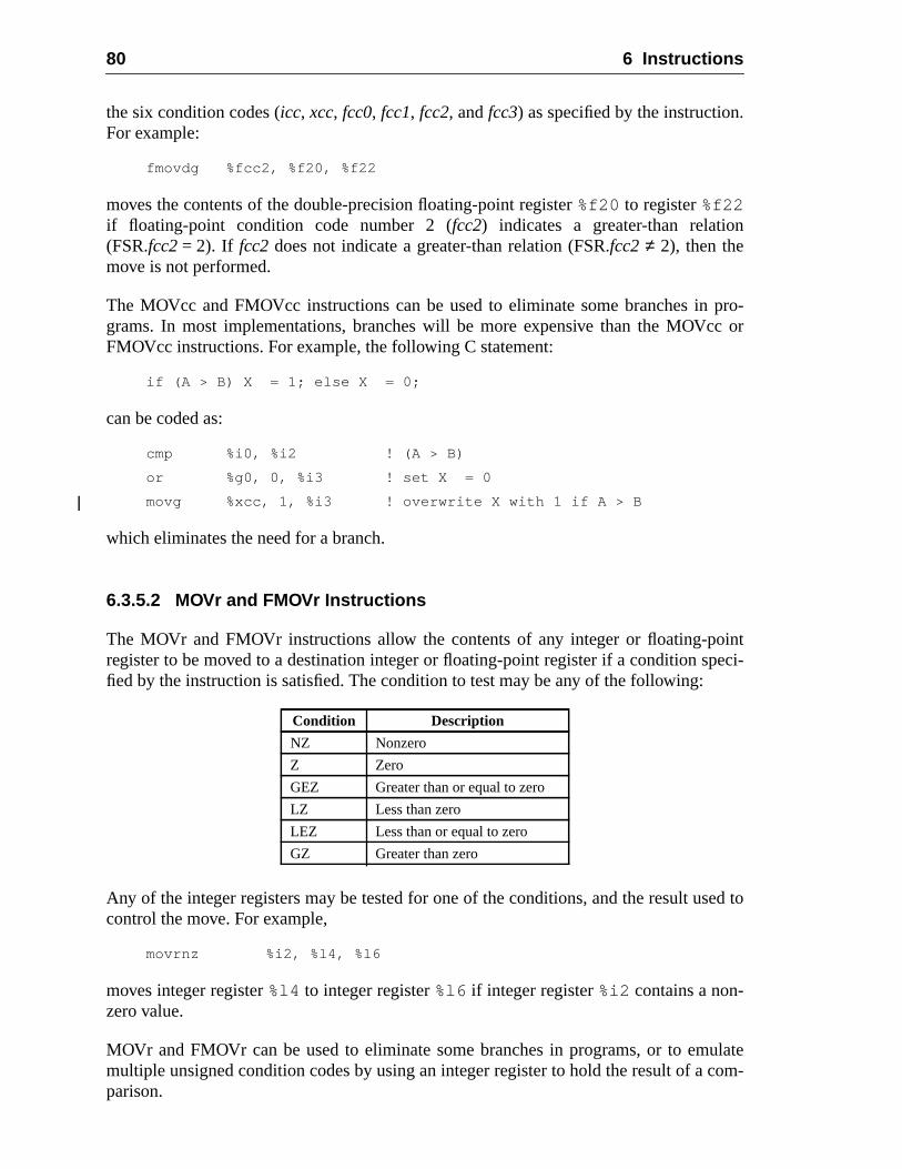
80 6 Instructions
.
n
pro-c or
inteci-
ed to
ulatecom-
the six condition codes (icc, xcc, fcc0, fcc1, fcc2, andfcc3) as specified by the instructionFor example:
fmovdg %fcc2, %f20, %f22
moves the contents of the double-precision floating-point register%f20 to register%f22if floating-point condition code number 2 (fcc2) indicates a greater-than relatio(FSR.fcc2= 2). If fcc2 does not indicate a greater-than relation (FSR.fcc2 ≠ 2), then themove is not performed.
The MOVcc and FMOVcc instructions can be used to eliminate some branches ingrams. In most implementations, branches will be more expensive than the MOVcFMOVcc instructions. For example, the following C statement:
if (A > B) X = 1; else X = 0;
can be coded as:
cmp %i0, %i2 ! (A > B)
or %g0, 0, %i3 ! set X = 0
movg %xcc, 1, %i3 ! overwrite X with 1 if A > B
which eliminates the need for a branch.
6.3.5.2 MOVr and FMOVr Instructions
The MOVr and FMOVr instructions allow the contents of any integer or floating-poregister to be moved to a destination integer or floating-point register if a condition spfied by the instruction is satisfied. The condition to test may be any of the following:
Any of the integer registers may be tested for one of the conditions, and the result uscontrol the move. For example,
movrnz %i2, %l4, %l6
moves integer register%l4 to integer register%l6 if integer register%i2 contains a non-zero value.
MOVr and FMOVr can be used to eliminate some branches in programs, or to emmultiple unsigned condition codes by using an integer register to hold the result of aparison.
Condition Description
NZ Nonzero
Z Zero
GEZ Greater than or equal to zero
LZ Less than zero
LEZ Less than or equal to zero
GZ Greater than zero
6.3 Instruction Categories 81
ARC-egis-
win-
AN-the
ten
g the
entsromsultWP
RE,
es adow
JMPLonly.allingtion.
6.3.6 Register Window Management Instructions
This subsection describes the instructions used to manage register windows in SPV9. The privileged registers affected by these instructions are described in 5.2.10, “Rter-Window State Registers.”
6.3.6.1 SAVE Instruction
The SAVE instruction allocates a new register window and saves the caller’s registerdow by incrementing the CWP register.
If CANSAVE = 0, execution of a SAVE instruction causes awindow_spill exception.
If CANSAVE ≠ 0, but the number of clean windows is zero, that is:
(CLEANWIN – CANRESTORE) = 0
then SAVE causes aclean_window exception.
If SAVE does not cause an exception, it performs an ADD operation, decrements CSAVE, and increments CANRESTORE. The source registers for the ADD are fromold window (the one to which CWP pointed before the SAVE), while the result is writinto a register in the new window (the one to which the incremented CWP points).
6.3.6.2 RESTORE Instruction
The RESTORE instruction restores the previous register window by decrementinCWP register.
If CANRESTORE = 0, execution of a RESTORE instruction causes awindow_fill excep-tion.
If RESTORE does not cause an exception, it performs an ADD operation, decremCANRESTORE, and increments CANSAVE. The source registers for the ADD are fthe “old” window (the one to which CWP pointed before the RESTORE), while the reis written into a register in the “new” window (the one to which the decremented Cpoints).
Programming Note:
The following describes a common convention for use of register windows, SAVE, RESTOCALL, and JMPL instructions.
A procedure is invoked by executing a CALL (or a JMPL) instruction. If the procedure requirregister window, it executes a SAVE instruction. A routine that does not allocate a register winof its own (possibly a leaf procedure) should not modify any windowed registers exceptout regis-ters 0 through 6. See H.1.2, “Leaf-Procedure Optimization.”
A procedure that uses a register window returns by executing both a RESTORE and ainstruction. A procedure that has not allocated a register window returns by executing a JMPLThe target address for the JMPL instruction is normally eight plus the address saved by the cinstruction, that is, to the instruction after the instruction in the delay slot of the calling instruc
82 6 Instructions
stackllo-
dow
0), so
dow
pace
= 0),
ts
ow,ingThe
The SAVE and RESTORE instructions can be used to atomically establish a new memorypointer in anr register and switch to a new or previous register window. See H.1.4, “Register Acation within a Window.”
6.3.6.3 SAVED Instruction
The SAVED instruction should be used by a spill trap handler to indicate that a winspill has completed successfully. It increments CANSAVE:
CANSAVE ← (CANSAVE + 1)
If the saved window belongs to a different address space (OTHERWIN≠ 0), it decrementsOTHERWIN:
OTHERWIN ← (OTHERWIN – 1)
Otherwise, the saved window belongs to the current address space (OTHERWIN =SAVED decrements CANRESTORE:
CANRESTORE← (CANRESTORE – 1)
6.3.6.4 RESTORED Instruction
The RESTORED instruction should be used by a fill trap handler to indicate that a winhas been filled successfully. It increments CANRESTORE:
CANRESTORE← (CANRESTORE+ 1)
If the restored window replaces a window that belongs to a different address s(OTHERWIN ≠ 0), it decrements OTHERWIN:
OTHERWIN ← (OTHERWIN – 1)
Otherwise, the restored window belongs to the current address space (OTHERWINso RESTORED decrements CANSAVE:
CANSAVE ← (CANSAVE – 1)
If CLEANWIN is less than NWINDOWS-1, the RESTORED instruction incremenCLEANWIN:
if (CLEANWIN < (NWINDOWS-1))then CLEANWIN ← (CLEANWIN + 1)
6.3.6.5 Flush Windows Instruction
The FLUSHW instruction flushes all of the register windows except the current windby performing repetitive spill traps. The FLUSHW instruction is implemented by causa spill trap if any register window (other than the current window) has valid contents.number of windows with valid contents is computed as
NWINDOWS – 2 – CANSAVE
6.3 Instruction Categories 83
ise,hes
gisters.
re vis-nto/
struc-ce the
oper-
codesand
uc-
ns
anyener-
n
and
f the
If this number is nonzero, the FLUSHW instruction causes a spill trap. OtherwFLUSHW has no effect. If the spill trap handler exits with a RETRY instruction, tFLUSHW instruction will continue causing spill traps until all the register windowexcept the current window have been flushed.
6.3.7 State Register Access
The read/write state register instructions access program-visible state and status reThese instructions read/write the state registers into/fromr registers. A read/write Ancil-lary State Register instruction is privileged only if the accessed register is privileged.
6.3.8 Privileged Register Access
The read/write privileged register instructions access state and status registers that aible only to privileged software. These instructions read/write privileged registers ifrom r registers. The read/write privileged register instructions are privileged.
6.3.9 Floating-Point Operate (FPop) Instructions
Floating-point operate instructions (FPops) are generally triadic-register-address intions. They compute a result that is a function of one or two source operands and plaresult in one or more destinationf registers. The exceptions are:
— Floating-point convert operations, which use one source and one destinationand
— Floating-point compare operations, which do not write to anf register, but updateone of thefccn fields of the FSR instead
The term “FPop” refers to those instructions encoded by the FPop1 and FPop2 opand doesnot include branches based on the floating-point condition codes (FBfccFBPfcc) or the load/store floating-point instructions.
The FMOVcc instructions function for the floating-point registers as the MOVcc instrtions do for the integer registers. See 6.3.5.1, “MOVcc and FMOVcc Instructions.”
The FMOVr instructions function for the floating-point registers as the MOVr instructiodo for the integer registers. See 6.3.5.2, “MOVr and FMOVr Instructions.”
If there is no floating-point unit present or if PSTATE.PEF = 0 or FPRS.FEF = 0,instruction that attempts to access an FPU register, including an FPop instruction, gates anfp_disabled exception.
All FPop instructions clear theftt field and set thecexcfield, unless they generate aexception. Floating-point compare instructions also write one of thefccnfields. All FPopinstructions that can generate IEEE exceptions set thecexcandaexcfields, unless theygenerate an exception. FABS(s,d,q), FMOV(s,d,q), FMOVcc(s,d,q), FMOVr(s,d,q),FNEG(s,d,q) cannot generate IEEE exceptions, so they clearcexc and leaveaexcunchanged. FMOVcc and FMOVr instructions clear these FSR fields regardless ovalue of the conditional predicate.
84 6 Instructions
ent,
not
tion
ouldere
anbits
stilld(s)cally,es ano
ap on
IMPL. DEP. #3: An implementation may indicate that a floating-point instruction did not produce acorrect IEEE STD 754-1985 result by generating a special unfinished_FPop or unimplemented_FPop exception. Privileged-mode software must emulate any functionality not present in the hard-ware.
6.3.10 Implementation-Dependent Instructions
SPARC-V9 provides two instructions that are entirely implementation-dependIMPDEP1 and IMPDEP2 (impl. dep. #106).
V8 Compatibility Note:
The IMPDEPn instructions replace the CPopn instructions in SPARC-V8.
See A.23, “Implementation-Dependent Instructions,” for more information.
6.3.11 Reserved Opcodes and Instruction Fields
If a conforming SPARC V9 implementation attempts to execute an instruction that isspecifically defined in this specification, it behaves as follows:
— If the instruction encodes an implementation-specific extension to the instrucset, that extension is executed.
— If the instruction does not encode an extension to the instruction set, but wdecode as a valid instruction if nonzero bits in reserved instruction field(s) wignored (read as 0): The recommended behavior is to generate anillegal_instruc-tion exception (or, in the FPop opcode space, anfp_exception_other exceptionwith FSR.ftt = 3 (unimplemented_FPop)). Alternatively, the implementation cignore the nonzero reserved field bits and execute the instruction as if thosehad been zero.
— If the instruction does not encode an extension to the instruction set and wouldnot decode as a valid instruction if nonzero bits in reserved instruction fielwere ignored, then the instruction is invalid and causes an exception. Specifiattempting to execute an invalid instruction in the FPop opcode space causfp_exception_other trap (with FSR.ftt = unimplemented_FPop); attempting texecute any other invalid instruction causes anillegal_instruction trap.
See Appendix E, “Opcode Maps,” for an enumeration of the reserved opcodes.
Implementation Note
As described above, implementations are strongly encouraged, but not strictly required, to trnonzero values in reserved instruction fields.
Programming Note:
For software portability, software (such as assemblers, static compilers, and dynamic compil-
ers) that generates SPARC instructions must always generate zeroes in instruction fields
marked "reserved" ("--").
6.4 Register Window Management 85
reg-fectedriv-
RPR
ays
bove
sosentthe
tion)are
usedin-
rrenttruc-
n thented
fol-
re, thedlersbecan
6.4 Register Window Management
The state of the register windows is determined by the contents of the set of privilegedisters described in 5.2.10, “Register-Window State Registers.” Those registers are afby the instructions described in 6.3.6, “Register Window Management Instructions.” Pileged software can read/write these state registers directly by using RDPR/Winstructions.
6.4.1 Register Window State Definition
In order for the state of the register windows to be consistent, the following must alwbe true:
CANSAVE + CANRESTORE+ OTHERWIN = NWINDOWS – 2
Figure 3 on page 34 shows how the register windows are partitioned to obtain the aequation. In figure 3, the partitions are as follows:
— The current window and the window that overlaps two other valid windows andmust not be used (in the figure, windows 0 and 4, respectively) are always preand account for the 2 subtracted from NWINDOWS in the right-hand side ofequation.
— Windows that do not have valid contents and can be used (via a SAVE instrucwithout causing a spill trap. These windows (windows 1, 2 and 3 in the figure)counted in CANSAVE.
— Windows that have valid contents for the current address space and can be(via the RESTORE instruction) without causing a fill trap. These windows (wdow 7 in the figure) are counted in CANRESTORE.
— Windows that have valid contents for an address space other than the cuaddress space. An attempt to use these windows via a SAVE (RESTORE) instion results in a spill (fill) trap to a separate set of trap vectors, as discussed ifollowing subsection. These windows (windows 5 and 6 in the figure) are couin OTHERWIN.
In addition,
CLEANWIN ≥ CANRESTORE
since CLEANWIN is the sum of CANRESTORE and the number of clean windowslowing CWP.
In order to use the window-management features of the architecture as described hestate of the register windows must be kept consistent at all times, except in trap hanfor window spilling, filling, and cleaning. While handling window traps the state mayinconsistent. Window spill/fill trap handlers should be written such that a nested trapbe taken without destroying state.
86 6 Instructions
win-
win-ed
e for
ioushat
on-ame
is-ace tother
o thet canwingat are
-
ple
ng towin-
as
ttinghree
6.4.2 Register Window Traps
Window traps are used to manage overflow and underflow conditions in the registerdows, to support clean windows, and to implement the FLUSHW instruction.
6.4.2.1 Window Spill and Fill Traps
A window overflow occurs when a SAVE instruction is executed and the next registerdow is occupied (CANSAVE = 0). An overflow causes a spill trap that allows privilegsoftware to save the occupied register window in memory, thereby making it availabluse.
A window underflow occurs when a RESTORE instruction is executed and the prevregister window is not valid (CANRESTORE = 0). An underflow causes a fill trap tallows privileged software to load the registers from memory.
6.4.2.2 Clean-Window Trap
SPARC-V9 provides theclean_window trap so that software can create a secure envirment in which it is guaranteed that register windows contain only data from the saddress space.
A clean register window is one in which all of the registers, including uninitialized regters, contain either zero or data assigned by software executing in the address spwhich the window belongs. A clean window cannot contain register values from anoprocess, that is, software operating in a different address space.
Supervisor software specifies the number of windows that are clean with respect tcurrent address space in the CLEANWIN register. This includes register windows thabe restored (the value in the CANRESTORE register) and the register windows folloCWP that can be used without cleaning. Therefore, the number of clean windows thavailable to be used by the SAVE instruction is
CLEANWIN – CANRESTORE
The SAVE instruction causes aclean_window trap if this value is zero. This allows supervisor software to clean a register window before it is accessed by a user.
6.4.2.3 Vectoring of Fill/Spill Traps
In order to make handling of fill and spill traps efficient, SPARC-V9 provides multitrap vectors for the fill and spill traps. These trap vectors are determined as follows:
— Supervisor software can mark a set of contiguous register windows as belongian address space different from the current one. The count of these registerdows is kept in the OTHERWIN register. A separate set of trap vectors (fill_n_otherandspill_n_other) is provided for spill and fill traps for these register windows (opposed to register windows that belong to the current address space).
— Supervisor software can specify the trap vectors for fill and spill traps by presethe fields in the WSTATE register. This register contains two subfields, each t
6.4 Register Window Management 87
ills toon-
e trap
isled
owsow
lyate ofmongt.
t it
ow
bits wide. The WSTATE.NORMAL field is used to determine one of eight sp(fill) vectors to be used when the register window to be spilled (filled) belongthe current address space (OTHERWIN = 0). If the OTHERWIN register is nzero, the WSTATE.OTHER field selects one of eightfill_n_other (spill_n_other) trapvectors.
See Chapter 7, “Traps,” for more details on how the trap address is determined.
6.4.2.4 CWP on Window Traps
On a window trap the CWP is set to point to the window that must be accessed by thhandler, as follows (note that all arithmetic on CWP is done modulo NWINDOWS):
— If the spill trap occurs due to a SAVE instruction (when CANSAVE = 0), therean overlap window between the CWP and the next register window to be spil
CWP← (CWP+ 2) mod NWINDOWS
If the spill trap occurs due to a FLUSHW instruction, there can be unused wind(CANSAVE) in addition to the overlap window, between the CWP and the windto be spilled
CWP← (CWP+ CANSAVE + 2) mod NWINDOWS
Implementation Note:All spill traps can use:
CWP← (CWP+ CANSAVE + 2) mod NWINDOWS
since CANSAVE is zero whenever a trap occurs due to a SAVE instruction.
— On a fill trap, the window preceding CWP must be filled
CWP← (CWP – 1)mod NWINDOWS
— On a clean_window trap, the window following CWP must be cleaned. Then
CWP← (CWP+ 1) mod NWINDOWS
6.4.2.5 Window Trap Handlers
The trap handlers for fill, spill andclean_window traps must handle the trap appropriateand return using the RETRY instruction, to reexecute the trapped instruction. The stthe register windows must be updated by the trap handler, and the relationship aCLEANWIN, CANSAVE, CANRESTORE, and OTHERWIN must remain consistenThe following recommendations should be followed:
— A spill trap handler should execute the SAVED instruction for each window thaspills.
— A fill trap handler should execute the RESTORED instruction for each windthat it fills.
88 6 Instructions
at
e for
— A clean_window trap handler should increment CLEANWIN for each window thit cleans:
CLEANWIN ← (CLEANWIN + 1)
Window trap handlers in SPARC-V9 can be very efficient. See H.2.2, “Example CodSpill Handler,” for details and sample code.
con-heBasetypeone-uarter
, and
turn.
cedelatedxecut-rruptcts the
tinuectionnce of
fromptionuch ans par-
7 Traps
7.1 Overview
A trap is a vectored transfer of control to supervisor software through a trap table thattains the first eight (thirty-two for fill/spill traps) instructions of each trap handler. Tbase address of the table is established by supervisor software, by writing the TrapAddress (TBA) register. The displacement within the table is determined by the trapand the current trap level (TL). One-half of the table is reserved for hardware traps;quarter is reserved for software traps generated by Tcc instructions; the remaining qis reserved for future use.
A trap behaves like an unexpected procedure call. It causes the hardware to
(1) Save certain processor state (program counters, CWP, ASI, CCR, PSTATEthe trap type) on a hardware register stack
(2) Enter privileged execution mode with a predefined PSTATE
(3) Begin executing trap handler code in the trap vector
When the trap handler has finished, it uses either a DONE or RETRY instruction to re
A trap may be caused by a Tcc instruction, an SIR instruction, an instruction-induexception, a reset, an asynchronous exception, or an interrupt request not directly rto a particular instruction. The processor must appear to behave as though, before eing each instruction, it determines if there are any pending exceptions or interequests. If there are pending exceptions or interrupt requests, the processor selehighest-priority exception or interrupt request and causes a trap.
Thus, an exception is a condition that makes it impossible for the processor to conexecuting the current instruction stream without software intervention. A trap is the ataken by the processor when it changes the instruction flow in response to the presean exception, interrupt, or Tcc instruction.
A catastrophic error exception is due to the detection of a hardware malfunctionwhich, due to the nature of the error, the state of the machine at the time of the excecannot be restored. Since the machine state cannot be restored, execution after sexception may not be resumable. An example of such an error is an uncorrectable buity error.
89
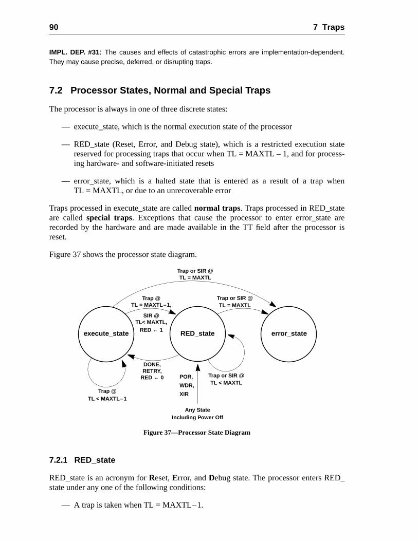
90 7 Traps
statess-
when
eare
sor is
_
IMPL. DEP. #31: The causes and effects of catastrophic errors are implementation-dependent.They may cause precise, deferred, or disrupting traps.
7.2 Processor States, Normal and Special Traps
The processor is always in one of three discrete states:
— execute_state, which is the normal execution state of the processor
— RED_state (Reset, Error, and Debug state), which is a restricted executionreserved for processing traps that occur when TL = MAXTL – 1, and for proceing hardware- and software-initiated resets
— error_state, which is a halted state that is entered as a result of a trapTL = MAXTL, or due to an unrecoverable error
Traps processed in execute_state are callednormal traps. Traps processed in RED_statare calledspecial traps. Exceptions that cause the processor to enter error_staterecorded by the hardware and are made available in the TT field after the procesreset.
Figure 37 shows the processor state diagram.
Figure 37—Processor State Diagram
7.2.1 RED_state
RED_state is an acronym forReset,Error, andDebug state. The processor enters REDstate under any one of the following conditions:
— A trap is taken when TL = MAXTL–1.
RED_stateexecute_state error_state
POR,
Including Power Off
Trap or SIR @
Trap or SIR @TL = MAXTL
Trap @TL = MAXTL–1,
DONE,
TL = MAXTL
RED ← 1
RED ← 0RETRY,
WDR,
Any State
Trap or SIR @TL < MAXTL
Trap @TL < MAXTL–1
XIR
SIR @TL< MAXTL,
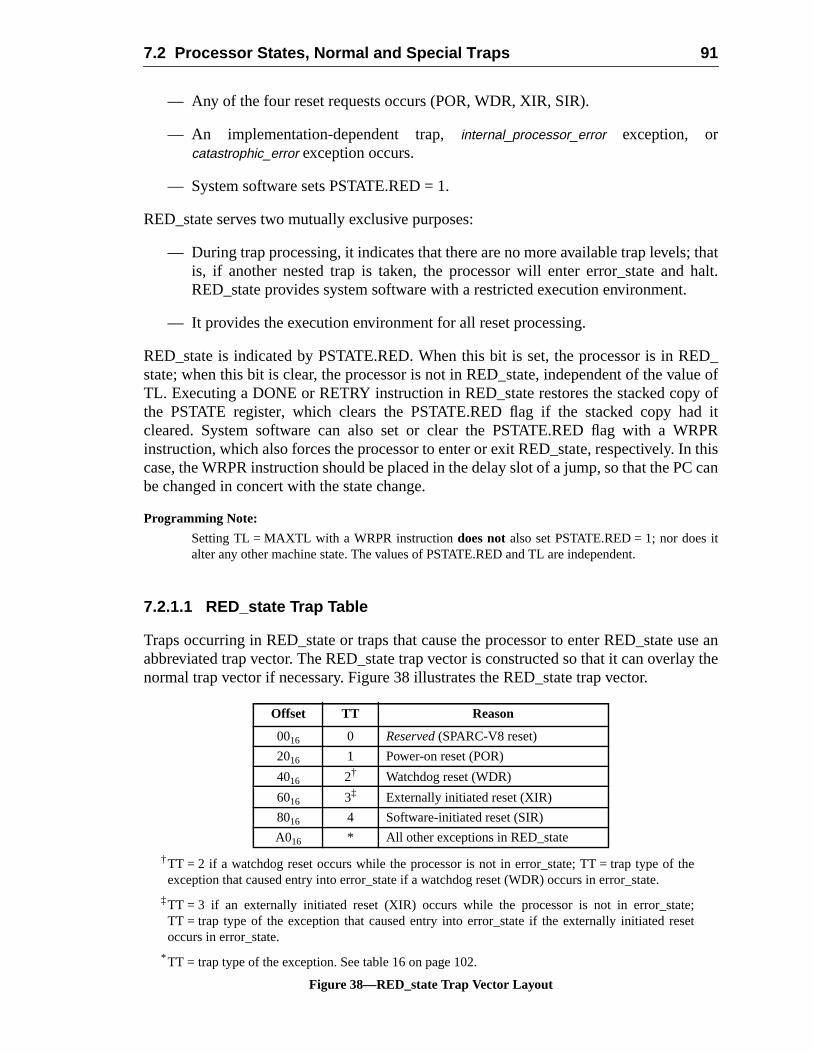
7.2 Processor States, Normal and Special Traps 91
; thathalt.
.
ED_lue ofy ofd itRPRn thisC can
t
use anay the
t
— Any of the four reset requests occurs (POR, WDR, XIR, SIR).
— An implementation-dependent trap,internal_processor_error exception, orcatastrophic_error exception occurs.
— System software sets PSTATE.RED = 1.
RED_state serves two mutually exclusive purposes:
— During trap processing, it indicates that there are no more available trap levelsis, if another nested trap is taken, the processor will enter error_state andRED_state provides system software with a restricted execution environment
— It provides the execution environment for all reset processing.
RED_state is indicated by PSTATE.RED. When this bit is set, the processor is in Rstate; when this bit is clear, the processor is not in RED_state, independent of the vaTL. Executing a DONE or RETRY instruction in RED_state restores the stacked copthe PSTATE register, which clears the PSTATE.RED flag if the stacked copy hacleared. System software can also set or clear the PSTATE.RED flag with a Winstruction, which also forces the processor to enter or exit RED_state, respectively. Icase, the WRPR instruction should be placed in the delay slot of a jump, so that the Pbe changed in concert with the state change.
Programming Note:
Setting TL = MAXTL with a WRPR instructiondoes notalso set PSTATE.RED = 1; nor does ialter any other machine state. The values of PSTATE.RED and TL are independent.
7.2.1.1 RED_state Trap Table
Traps occurring in RED_state or traps that cause the processor to enter RED_stateabbreviated trap vector. The RED_state trap vector is constructed so that it can overlnormal trap vector if necessary. Figure 38 illustrates the RED_state trap vector.
†TT = 2 if a watchdog reset occurs while the processor is not in error_state; TT = trap type of theexception that caused entry into error_state if a watchdog reset (WDR) occurs in error_state.
‡TT = 3 if an externally initiated reset (XIR) occurs while the processor is not in error_state;TT = trap type of the exception that caused entry into error_state if the externally initiated reseoccurs in error_state.
* TT = trap type of the exception. See table 16 on page 102.
Figure 38—RED_state Trap Vector Layout
Offset TT Reason
0016 0 Reserved (SPARC-V8 reset)
2016 1 Power-on reset (POR)
4016 2† Watchdog reset (WDR)
6016 3‡ Externally initiated reset (XIR)
8016 4 Software-initiated reset (SIR)
A016 * All other exceptions in RED_state
92 7 Traps
valueetta-
riding
, the
it isso dis-
ystems, if acitlyor is
ities
ED_
r fromate istem to a
IMPL. DEP. #114: The RED_state trap vector is located at an implementation-dependent addressreferred to as RSTVaddr.
Implementation Note:
The RED_state trap handlers should be located in trusted memory, for example, in ROM. Theof RSTVaddr may be hard-wired in an implementation, but it is suggested that it be externally sble, for instance by scan, or read from pins at power-on reset.
7.2.1.2 RED_state Execution Environment
In RED_state the processor is forced to execute in a restricted environment by overthe values of some processor controls and state registers.
Programming Note:
The values are overridden, not set. This is to allow them to be switched atomically.
IMPL. DEP. #115: A processor’s behavior in RED_state is implementation-dependent.
The following are recommended:
(1) Instruction address translation is a straight-through physical map; that isMMU is always suppressed for instruction access in RED_state.
(2) Data address translation is handled normally; that is, the MMU is used ifenabled. However, any event that causes the processor to enter RED_state alables the MMU. The handler executing in RED_state can reenable the MMU.
(3) All references are uncached.
(4) Cache coherence in RED_state is the problem of the system designer and sprogrammer. Normally, cache enables are left unchanged by RED_state; thucache is enabled, it will continue to participate in cache coherence until explidisabled by recovery code. A cache may be disabled automatically if an errdetected in the cache.
(5) Unessential functional units (for example, the floating-point unit) and capabil(for example, superscalar execution) should be disabled.
(6) If a store buffer is present, it should be emptied, if possible, before entering Rstate.
(7) PSTATE.MM is set to TSO.
Programming Note:
When RED_state is entered due to component failures, the handler should attempt to recovepotentially catastrophic error conditions or to disable the failing components. When RED_stentered after a reset, the software should create the environment necessary to restore the sysrunning state.
7.2 Processor States, Normal and Special Traps 93
is
35).
abling
an-
= 1,
ndler
ssing.ess-
7.2.1.3 RED_state Entry Traps
The following traps are processed in RED_state in all cases
— POR (Power-on reset)
— WDR (Watchdog reset)
— XIR (Externally initiated reset)
In addition, the following trap is processed in RED_state if TL < MAXTL when the traptaken. Otherwise it is processed in error_state.
— SIR (Software-initiated Reset)
An implementation also may elect to set PSTATE.RED = 1 after aninternal_processor_error trap (impl. dep. #31), or any of the implementation-dependent traps (impl. dep. #
Implementation-dependent traps may force additional state changes, such as disfailing components.
Traps that occur when TL = MAXTL – 1 also set PSTATE.RED = 1; that is, any trap hdler entered with TL = MAXTL runs in RED_state.
Any nonreset trap that sets PSTATE.RED = 1 or that occurs when PSTATE.REDbranches to a special entry in the RED_state trap vector at RSTVaddr + A016.
In systems in which it is desired that traps not enter RED_state, the RED_state hamay transfer to the normal trap vector by executing the following code:
! Assumptions:
! -- In RED_state handler, therefore we know that
! PSTATE.RED = 1, so a WRPR can directly toggle it to 0
! and, we don’t have to worry about intervening traps.
! -- Registers %g1 and %g2 are available as scratch registers.
...
#define PSTATE_RED 0x0020 ! PSTATE.RED is bit 5
...
rdpr %tt,%g1 ! Get the normal trap vector
rdpr %tba,%g2 ! address in %g2.
sllx %g1,5,%g1
add %g1,%g2,%g2
rdpr %pstate,%g1 ! Read PSTATE into %g1.
jmpl %g2 ! Jump to normal trap vector,
wrpr %g1,PSTATE_RED,%pstate ! toggling PSTATE.RED to 0.
7.2.1.4 RED_state Software Considerations
In effect, RED_state reserves one level of the trap stack for recovery and reset proceSoftware should be designed to require only MAXTL – 1 trap levels for normal proc
94 7 Traps
uld
s:
registerrve one
y at its
state.
ly, itOR).
_statee timerig-R.
ing. That is, any trap that causes TL = MAXTL is an exceptional condition that shocause entry to RED_state.
Since the minimum value for MAXTL is 4, typical usage of the trap levels is as follow
Programming Note:
In order to log the state of the processor, RED_state-handler software needs either a spareor a preloaded pointer to a save area. To support recovery, the operating system might reseof the alternate global registers, (for example,%a7) for use in RED_state.
7.2.2 Error_state
The processor enters error_state when a trap occurs while the processor is alreadmaximum supported trap level, that is, when TL = MAXTL.
IMPL. DEP. #39: The processor may enter error_state when an implementation-dependent errorcondition occurs.
IMPL. DEP. #40: Effects when error_state is entered are implementation-dependent, but it is rec-ommended that as much processor state as possible be preserved upon entry to error_state.
In particular:
(1) The processor should present an external indication that it has entered error_
(2) The processor should halt, that is, make no further changes to system state.
(3) The processor should be restarted by a watchdog reset (WDR). Alternativemay be restarted by an externally initiated reset (XIR) or a power-on reset (P
After a reset that brings the processor out of error_state, the processor enters REDwith TL set as defined in table 20 on page 106; the trap state describes the state at thof entry into error_state. In particular, for WDR and XIR, TT is set to the value of the oinal trap that caused entry to error_state, not the normal TT value for the WDR or XI
7.3 Trap Categories
An exception or interrupt request can cause any of the following trap types:
— A precise trap
TL Usage
0 Normal execution
1 System calls; interrupt handlers; instruction emulation
2 Window spill / fill
3 Page-fault handler
4 RED_state handler
7.3 Trap Categories 95
isi-ccurs,
thet.
xecu-
.
struc-
xecut-
, ae mayy one
y, thexcep-
to be
ntains-trap-
— A deferred trap
— A disrupting trap
— A reset trap
7.3.1 Precise Traps
A precise trap is induced by a particular instruction and occurs before any program-vble state has been changed by the trap-inducing instruction. When a precise trap oseveral conditions must be true.
— The PC saved in TPC[TL] points to the instruction that induced the trap, andnPC saved in NTPC[TL] points to the instruction that was to be executed nex
— All instructions issued before the one that induced the trap have completed etion.
— Any instructions issued after the one that induced the trap remain unexecuted
Programming Note:
Among the actions the trap handler software might take after a precise trap are:
— Return to the instruction that caused the trap and reexecute it, by executing a RETRY in
tion (PC← old PC, nPC← old nPC)
— Emulate the instruction that caused the trap and return to the succeeding instruction by e
ing a DONE instruction (PC← old nPC, nPC← old nPC + 4)
— Terminate the program or process associated with the trap
7.3.2 Deferred Traps
A deferred trap is also induced by a particular instruction, but unlike a precise trapdeferred trap may occur after program-visible state has been changed. Such stathave been changed by the execution of either the trap-inducing instruction itself or bor more other instructions.
If an instruction induces a deferred trap and a precise trap occurs simultaneousldeferred trap may not be deferred past the precise trap, except that a floating-point etion may be deferred past a precise trap.
Associated with a particular deferred-trap implementation, there must exist:
— An instruction that causes a potentially outstanding deferred-trap exceptiontaken as a trap.
— Privileged instructions that access the deferred-trap queues. This queue cothe state information needed by supervisor software to emulate the deferred
96 7 Traps
am.
com-rred-
te allger(e.g.,
execu-ETRY
sedis-viced,reset
PIL)is
rupt
revi-ction.uced
state.rupt
to ationhich
imple-
inducing instruction, and to resume execution of the trapped instruction streSee 5.2.13, “IU Deferred-Trap Queue.”)
Note that resuming execution may require the emulation of instructions that had notpleted execution at the time of the deferred trap, that is, those instructions in the defetrap queue.
IMPL. DEP. #32: Whether any deferred traps (and associated deferred-trap queues) are present isimplementation-dependent.
Note that to avoid deferred traps entirely, an implementation would need to execuimplemented floating-point instructions synchronously with the execution of inteinstructions, causing all generated exceptions to be precise. A deferred-trap queueFQ) would be superfluous in such an implementation.
Programming Note:
Among the actions software can take after a deferred trap are:
— Emulate the instruction that caused the exception, emulate or cause to execute any othertion-deferred instructions that were in an associated deferred-trap state queue, and use Rto return control to the instruction at which the deferred trap was invoked, or
— Terminate the program or process associated with the trap.
7.3.3 Disrupting Traps
A disrupting trap is neither a precise trap nor a deferred trap. A disrupting trap is cauby acondition (e.g., an interrupt), rather than directly by a particular instruction; this dtinguishes it from precise and deferred traps. When a disrupting trap has been serprogram execution resumes where it left off. This differentiates disrupting traps fromtraps, which resume execution at the unique reset address.
Disrupting traps are controlled by a combination of the Processor Interrupt Level (register and the Interrupt Enable (IE) field of PSTATE. A disrupting trap conditionignored when interrupts are disabled (PSTATE.IE = 0) or when the condition’s interlevel is lower than that specified in PIL.
A disrupting trap may be due to either an interrupt request not directly related to a pously executed instruction, or to an exception related to a previously executed instruInterrupt requests may be either internal or external. An interrupt request can be indby the assertion of a signal not directly related to any particular processor or memoryExamples of this are the assertion of an “I/O done” signal or setting external interrequest lines.
A disrupting trap related to an earlier instruction causing an exception is similardeferred trap in that it occurs after instructions following the trap-inducing instruchave modified the processor or memory state. The difference is that the condition wcaused the instruction to induce the trap may lead to unrecoverable errors, since the
7.3 Trap Categories 97
access
ter-ptingreset
criti-
m
uent
mentation may not preserve the necessary state. An example of this is an ECC data-error reported after the corresponding load instruction has completed.
Disrupting trap conditions should persist until the corresponding trap is taken.
Programming Note:Among the actions that trap-handler software might take after a disrupting trap are:
— Use RETRY to return to the instruction at which the trap was invoked
(PC← old PC, nPC← old nPC), or
— Terminate the program or process associated with the trap.
7.3.4 Reset Traps
A reset trap occurs when supervisor software or the implementation’s hardware demines that the machine must be reset to a known state. Reset traps differ from disrutraps, since they do not resume execution of the program that was running when thetrap occurred.
IMPL. DEP. #37: Some of a processor’s behavior during a reset trap is implementation-dependent.See 7.6.2, “Special Trap Processing,” for details.
The following reset traps are defined for SPARC-V9:
Software-initiated reset (SIR):Initiated by software by executing the SIR instruction.
Power-on reset (POR):Initiated when power is applied (or reapplied) to the processor.
Watchdog reset (WDR):Initiated in response to error_state or expiration of a watchdog timer.
Externally initiated reset (XIR) :Initiated in response to an external signal. This reset trap is normally used forcal system events, such as power failure.
7.3.5 Uses of the Trap Categories
The SPARC-V9trap model stipulates that:
(1) Reset traps, exceptsoftware_initiated_reset traps, occur asynchronously to prograexecution.
(2) When recovery from an exception can affect the interpretation of subseqinstructions, such exceptions shall be precise. These exceptions are:
— software_initiated_reset
— instruction_access_exception
— privileged_action
— privileged_opcode
98 7 Traps
storeatus, a
emory
red, or
ch as
of anavethe
n theubse-yond; they notting-ddi-
— trap_instruction
— instruction_access_error
— clean_window
— fp_disabled
— LDDF_mem_address_not_aligned
— STDF_mem_address_not_aligned
— tag_overflow
— unimplemented_LDD
— unimplemented_STD
— spill_n_normal
— spill_n_other
— fill_n_normal
— fill_n_other
(3) IMPL. DEP. #33: Exceptions that occur as the result of program execution may be preciseor deferred, although it is recommended that such exceptions be precise. Examples:mem_address_not_aligned, division_by_zero.
(4) An exception caused after the initial access of a multiple-access load orinstruction (load-store doubleword, LDSTUB, CASA, CASXA, or SWAP) thcauses a catastrophic exception may be precise, deferred, or disrupting. Thtrap due to the second memory access can occur after the processor or mstate has been modified by the first access.
(5) Implementation-dependent catastrophic exceptions may cause precise, deferdisrupting traps (impl. dep. #31).
(6) Exceptions caused by external events unrelated to the instruction stream, suinterrupts, are disrupting.
For the purposes of this subsection, we must distinguish between the dispatchinstruction and its execution by some functional unit. An instruction is deemed to hbeendispatched when the software-visible PC advances beyond that instruction ininstruction stream. An instruction is deemed to have beenexecutedwhen the results ofthat instruction are available to subsequent instructions.
For most instructions, dispatch and execution appear to occur simultaneously; whePC has advanced beyond the instruction, its results are immediately available to squent instructions. For floating-point instructions, however, the PC may advance bethe instruction as soon as the IU places the instruction into a floating-point queueinstruction itself may not have completed (or even begun) execution, and results mabe available to subsequent instructions for some time. In particular, the fact that a floapoint instruction will generate an exception may not be noticed by the hardware until a
7.4 Trap Control 99
ates
n isssarilyis, aource
te that
red,oint
eptionstruc-g float-e
IL)
bleat-
ther
ll be
andcep-p-
will
tional floating-point instructions have been placed into the queue by the IU. This crethe condition for a deferred trap.
A deferred trap may occur one or more instructions after the trap-inducing instructiodispatched. However, a deferred trap must occur before the execution (but not necethe dispatch) of any instruction that depends on the trap-inducing instruction. Thatdeferred trap may not be deferred past the execution of an instruction that specifies sregisters, destination registers, condition codes, or any software-visible machine stacould be modified by the trap-inducing instruction.
In the case of floating-point instructions, if a floating-point exception is currently deferan attempt to dispatch a floating-point instruction (FPop, FBfcc, FBPfcc, or floating-pload/store) invokes or causes the outstandingfp_exception_ieee_754 trap.
Implementation Note:
To provide the capability to terminate a user process on the occurrence of a catastrophic excthat can cause a deferred or disrupting trap, an implementation should provide one or more intions that provoke an outstanding exception to be taken as a trap. For example, an outstandining-point exception might cause anfp_exception_ieee_754 trap when any of an FPop, load or storfloating-point register (including the FSR), FBfcc, or FBPfcc instruction is executed.
7.4 Trap Control
Several registers control how any given trap is processed:
— The interrupt enable (IE) field in PSTATE and the processor interrupt level (Pregister control interrupt processing.
— The enable floating-point unit (FEF) field in FPRS, the floating-point unit ena(PEF) field in PSTATE, and the trap enable mask (TEM) in the FSR control floing-point traps.
— The TL register, which contains the current level of trap nesting, controls whea trap causes entry to execute_state, RED_state, or error_state.
— PSTATE.TLE determines whether implicit data accesses in the trap routine wiperformed using the big- or little-endian byte order.
7.4.1 PIL Control
Between the execution of instructions, the IU prioritizes the outstanding exceptionsinterrupt requests according to table 17. At any given time, only the highest priority extion or interrupt request is taken as a trap.1 When there are multiple outstanding excetions or interrupt requests, SPARC-V9 assumes that lower-priority interrupt requests
1. The highest priority exception or interrupt is the one with the lowest priority value in table 17. Forexample, a priority 2 exception is processed before a priority 3 exception.
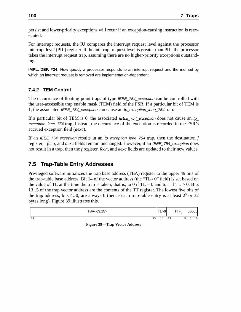
100 7 Traps
ex-
essorssorstand-
M is
R’s
s.
its ofed onitsits of
persist and lower-priority exceptions will recur if an exception-causing instruction is reecuted.
For interrupt requests, the IU compares the interrupt request level against the procinterrupt level (PIL) register. If the interrupt request level is greater than PIL, the procetakes the interrupt request trap, assuming there are no higher-priority exceptions outing
IMPL. DEP. #34: How quickly a processor responds to an interrupt request and the method bywhich an interrupt request is removed are implementation-dependent.
7.4.2 TEM Control
The occurrence of floating-point traps of typeIEEE_754_exception can be controlled withthe user-accessible trap enable mask (TEM) field of the FSR. If a particular bit of TE1, the associatedIEEE_754_exception can cause anfp_exception_ieee_754 trap.
If a particular bit of TEM is 0, the associatedIEEE_754_exception does not cause anfp_exception_ieee_754 trap. Instead, the occurrence of the exception is recorded in the FSaccrued exception field (aexc).
If an IEEE_754_exception results in anfp_exception_ieee_754 trap, then the destinationfregister, fccn, andaexcfields remain unchanged. However, if anIEEE_754_exception doesnot result in a trap, then thef register,fccn, andaexcfields are updated to their new value
7.5 Trap-Table Entry Addresses
Privileged software initializes the trap base address (TBA) register to the upper 49 bthe trap-table base address. Bit 14 of the vector address (the “TL>0” field) is set basthe value of TL at the time the trap is taken; that is, to 0 if TL = 0 and to 1 if TL > 0. B13..5 of the trap vector address are the contents of the TT register. The lowest five bthe trap address, bits 4..0, are always 0 (hence each trap-table entry is at least 25 or 32bytes long). Figure 39 illustrates this.
Figure 39—Trap Vector Address
63 15 14 0
TBA<63:15>
13 45
TL>0 TTTL 00000
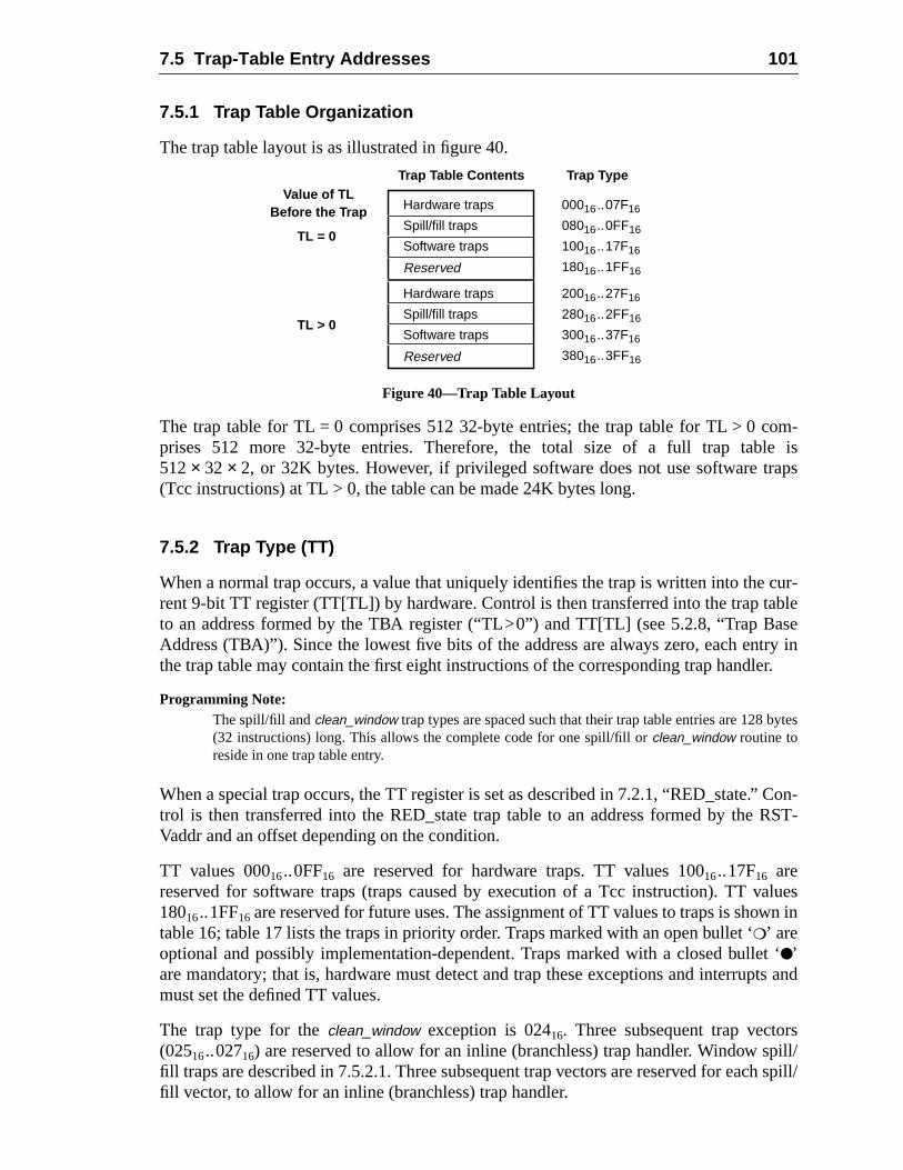
7.5 Trap-Table Entry Addresses 101
om-e isaps
cur-blese
try iner.
ytes
Con-RST-
alueswn in
t ‘ts and
spill/h spill/
7.5.1 Trap Table Organization
The trap table layout is as illustrated in figure 40.
Figure 40—Trap Table Layout
The trap table for TL = 0 comprises 512 32-byte entries; the trap table for TL > 0 cprises 512 more 32-byte entries. Therefore, the total size of a full trap tabl512× 32 × 2, or 32K bytes. However, if privileged software does not use software tr(Tcc instructions) at TL > 0, the table can be made 24K bytes long.
7.5.2 Trap Type (TT)
When a normal trap occurs, a value that uniquely identifies the trap is written into therent 9-bit TT register (TT[TL]) by hardware. Control is then transferred into the trap tato an address formed by the TBA register (“TL>0”) and TT[TL] (see 5.2.8, “Trap BaAddress (TBA)”). Since the lowest five bits of the address are always zero, each enthe trap table may contain the first eight instructions of the corresponding trap handl
Programming Note:The spill/fill andclean_window trap types are spaced such that their trap table entries are 128 b(32 instructions) long. This allows the complete code for one spill/fill orclean_window routine toreside in one trap table entry.
When a special trap occurs, the TT register is set as described in 7.2.1, “RED_state.”trol is then transferred into the RED_state trap table to an address formed by theVaddr and an offset depending on the condition.
TT values 00016..0FF16 are reserved for hardware traps. TT values 10016..17F16 arereserved for software traps (traps caused by execution of a Tcc instruction). TT v18016..1FF16 are reserved for future uses. The assignment of TT values to traps is shotable 16; table 17 lists the traps in priority order. Traps marked with an open bullet ‘❍’ areoptional and possibly implementation-dependent. Traps marked with a closed bulle●’are mandatory; that is, hardware must detect and trap these exceptions and interrupmust set the defined TT values.
The trap type for theclean_window exception is 02416. Three subsequent trap vector(02516..02716) are reserved to allow for an inline (branchless) trap handler. Window sfill traps are described in 7.5.2.1. Three subsequent trap vectors are reserved for eacfill vector, to allow for an inline (branchless) trap handler.
Value of TLBefore the Trap
Trap Table Contents Trap Type
TL = 0
Hardware traps
Spill/fill traps
Software traps
Reserved
00016..07F16
08016..0FF16
10016..17F16
18016..1FF16
TL > 0
Hardware traps
Spill/fill traps
Software traps
Reserved
20016..27F16
28016..2FF16
30016..37F16
38016..3FF16
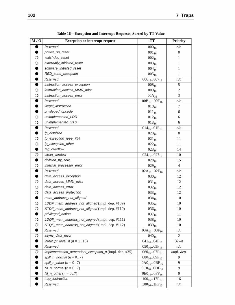
102 7 Traps
Table 16—Exception and Interrupt Requests, Sorted by TT Value
M / O Exception or interrupt request TT Priority
● Reserved 00016 n/a
● power_on_reset 00116 0
❍ watchdog_reset 00216 1
❍ externally_initiated_reset 00316 1
● software_initiated_reset 00416 1
● RED_state_exception 00516 1
● Reserved 00616..00716 n/a
● instruction_access_exception 00816 5
❍ instruction_access_MMU_miss 00916 2
❍ instruction_access_error 00A16 3
● Reserved 00B16..00F16 n/a
● illegal_instruction 01016 7
● privileged_opcode 01116 6
❍ unimplemented_LDD 01216 6
❍ unimplemented_STD 01316 6
● Reserved 01416..01F16 n/a
● fp_disabled 02016 8
❍ fp_exception_ieee_754 02116 11
❍ fp_exception_other 02216 11
● tag_overflow 02316 14
❍ clean_window 02416..02716 10
● division_by_zero 02816 15
❍ internal_processor_error 02916 4
● Reserved 02A16..02F16 n/a
● data_access_exception 03016 12
❍ data_access_MMU_miss 03116 12
❍ data_access_error 03216 12
❍ data_access_protection 03316 12
● mem_address_not_aligned 03416 10
❍ LDDF_mem_address_not_aligned (impl. dep. #109) 03516 10
❍ STDF_mem_address_not_aligned (impl. dep. #110) 03616 10
● privileged_action 03716 11
❍ LDQF_mem_address_not_aligned (impl. dep. #111) 03816 10
❍ STQF_mem_address_not_aligned (impl. dep. #112) 03916 10
● Reserved 03A16..03F16 n/a
❍ async_data_error 04016 2
● interrupt_level_n (n = 1..15) 04116..04F16 32–n
● Reserved 05016..05F16 n/a
❍ implementation_dependent_exception_n (impl. dep. #35) 06016..07F16 impl.-dep.
● spill_n_normal (n = 0..7) 08016..09F16 9
● spill_n_other (n = 0..7) 0A016..0BF16 9
● fill_n_normal (n = 0..7) 0C016..0DF16 9
● fill_n_other (n = 0..7) 0E016..0FF16 9
● trap_instruction 10016..17F16 16
● Reserved 18016..1FF16 n/a
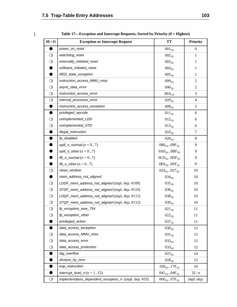
7.5 Trap-Table Entry Addresses 103
Table 17—Exception and Interrupt Requests, Sorted by Priority (0 = Highest)
M / O Exception or Interrupt Request TT Priority
● power_on_reset 00116 0
❍ watchdog_reset 00216 1
❍ externally_initiated_reset 00316 1
● software_initiated_reset 00416 1
● RED_state_exception 00516 1
❍ instruction_access_MMU_miss 00916 2
❍ async_data_error 04016 2
❍ instruction_access_error 00A16 3
❍ internal_processor_error 02916 4
● instruction_access_exception 00816 5
● privileged_opcode 01116 6
❍ unimplemented_LDD 01216 6
❍ unimplemented_STD 01316 6
● illegal_instruction 01016 7
● fp_disabled 02016 8
● spill_n_normal (n = 0..7) 08016..09F16 9
● spill_n_other (n = 0..7) 0A016..0BF16 9
● fill_n_normal (n = 0..7) 0C016..0DF16 9
● fill_n_other (n = 0..7) 0E016..0FF16 9
❍ clean_window 02416..02716 10
● mem_address_not_aligned 03416 10
❍ LDDF_mem_address_not_aligned (impl. dep. #109) 03516 10
❍ STDF_mem_address_not_aligned (impl. dep. #110) 03616 10
❍ LDQF_mem_address_not_aligned (impl. dep. #111) 03816 10
❍ STQF_mem_address_not_aligned (impl. dep. #112) 03916 10
❍ fp_exception_ieee_754 02116 11
❍ fp_exception_other 02216 11
● privileged_action 03716 11
● data_access_exception 03016 12
❍ data_access_MMU_miss 03116 12
❍ data_access_error 03216 12
❍ data_access_protection 03316 12
● tag_overflow 02316 14
● division_by_zero 02816 15
● trap_instruction 10016..17F16 16
● interrupt_level_n (n = 1..15) 04116..04F16 32–n
❍ implementation_dependent_exception_n (impl. dep. #35) 06016..07F16 impl.-dep.
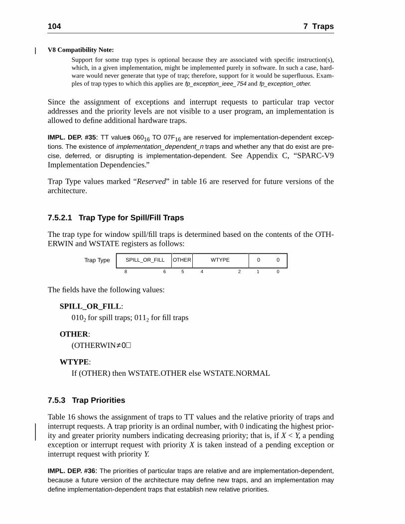
104 7 Traps
ion(s),hard-xam-
ectorion is
e
TH-
s andior-
r
V8 Compatibility Note:
Support for some trap types is optional because they are associated with specific instructwhich, in a given implementation, might be implemented purely in software. In such a case,ware would never generate that type of trap; therefore, support for it would be superfluous. Eples of trap types to which this applies arefp_exception_ieee_754 and fp_exception_other.
Since the assignment of exceptions and interrupt requests to particular trap vaddresses and the priority levels are not visible to a user program, an implementatallowed to define additional hardware traps.
IMPL. DEP. #35: TT values 06016 TO 07F16 are reserved for implementation-dependent excep-tions. The existence of implementation_dependent_n traps and whether any that do exist are pre-cise, deferred, or disrupting is implementation-dependent. See Appendix C, “SPARC-V9Implementation Dependencies.”
Trap Type values marked “Reserved” in table 16 are reserved for future versions of tharchitecture.
7.5.2.1 Trap Type for Spill/Fill Traps
The trap type for window spill/fill traps is determined based on the contents of the OERWIN and WSTATE registers as follows:
The fields have the following values:
SPILL_OR_FILL :
0102 for spill traps; 0112 for fill traps
OTHER :
(OTHERWIN≠0)
WTYPE :
If (OTHER) then WSTATE.OTHER else WSTATE.NORMAL
7.5.3 Trap Priorities
Table 16 shows the assignment of traps to TT values and the relative priority of trapinterrupt requests. A trap priority is an ordinal number, with 0 indicating the highest prity and greater priority numbers indicating decreasing priority; that is, ifX < Y, a pendingexception or interrupt request with priorityX is taken instead of a pending exception ointerrupt request with priorityY.
IMPL. DEP. #36: The priorities of particular traps are relative and are implementation-dependent,because a future version of the architecture may define new traps, and an implementation maydefine implementation-dependent traps that establish new relative priorities.
Trap Type
05 2
0SPILL_OR_FILL
1468
0WTYPEOTHER
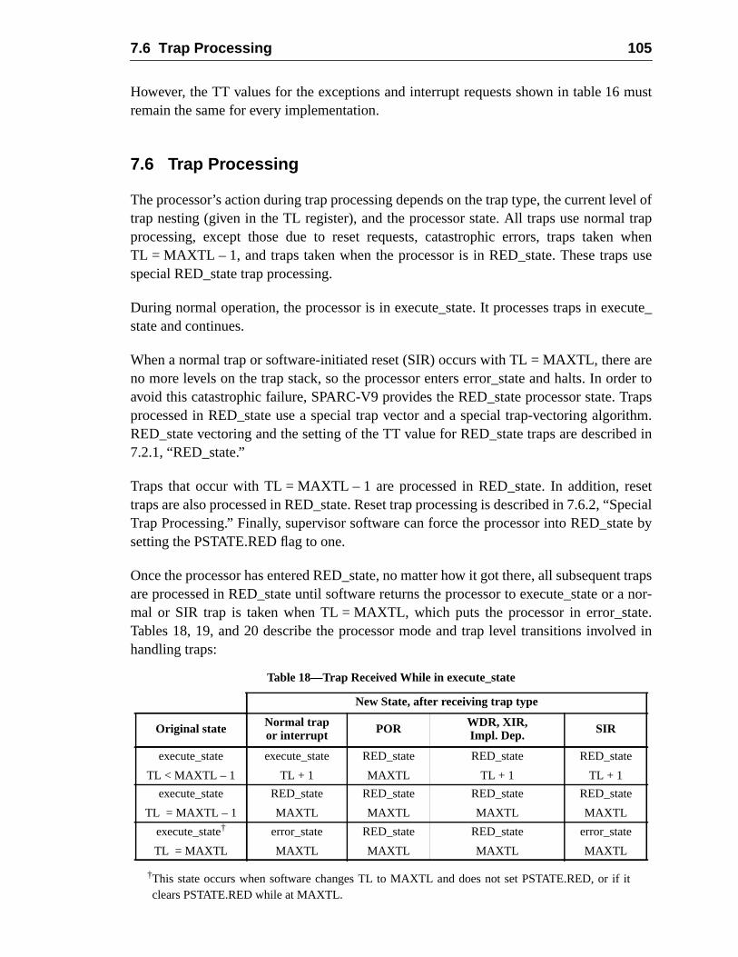
7.6 Trap Processing 105
must
evel ofl trap
whenuse
ecute_
arerder toTrapsrithm.ed in
setSpecialte by
nt trapsr a nor-ate.ved in
However, the TT values for the exceptions and interrupt requests shown in table 16remain the same for every implementation.
7.6 Trap Processing
The processor’s action during trap processing depends on the trap type, the current ltrap nesting (given in the TL register), and the processor state. All traps use normaprocessing, except those due to reset requests, catastrophic errors, traps takenTL = MAXTL – 1, and traps taken when the processor is in RED_state. These trapsspecial RED_state trap processing.
During normal operation, the processor is in execute_state. It processes traps in exstate and continues.
When a normal trap or software-initiated reset (SIR) occurs with TL = MAXTL, thereno more levels on the trap stack, so the processor enters error_state and halts. In oavoid this catastrophic failure, SPARC-V9 provides the RED_state processor state.processed in RED_state use a special trap vector and a special trap-vectoring algoRED_state vectoring and the setting of the TT value for RED_state traps are describ7.2.1, “RED_state.”
Traps that occur with TL = MAXTL – 1 are processed in RED_state. In addition, retraps are also processed in RED_state. Reset trap processing is described in 7.6.2, “Trap Processing.” Finally, supervisor software can force the processor into RED_stasetting the PSTATE.RED flag to one.
Once the processor has entered RED_state, no matter how it got there, all subsequeare processed in RED_state until software returns the processor to execute_state omal or SIR trap is taken when TL = MAXTL, which puts the processor in error_stTables 18, 19, and 20 describe the processor mode and trap level transitions involhandling traps:
†This state occurs when software changes TL to MAXTL and does not set PSTATE.RED, or if itclears PSTATE.RED while at MAXTL.
Table 18—Trap Received While in execute_state
New State, after receiving trap type
Original state Normal trapor interrupt POR WDR, XIR,
Impl. Dep. SIR
execute_state
TL < MAXTL – 1
execute_state
TL + 1
RED_state
MAXTL
RED_state
TL + 1
RED_state
TL + 1
execute_state
TL = MAXTL – 1
RED_state
MAXTL
RED_state
MAXTL
RED_state
MAXTL
RED_state
MAXTL
execute_state†
TL = MAXTL
error_state
MAXTL
RED_state
MAXTL
RED_state
MAXTL
error_state
MAXTL
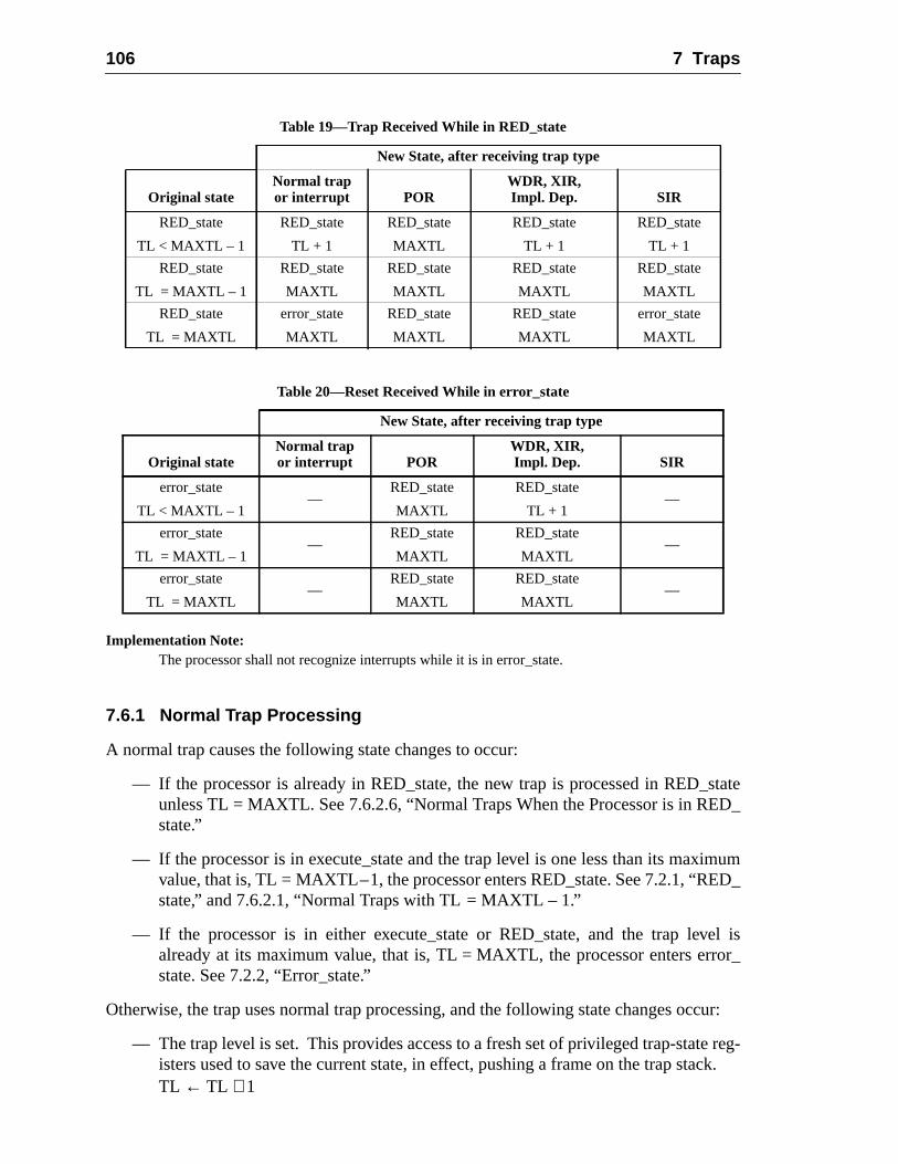
106 7 Traps
stateD_
imumD_
el isor_
cur:
reg-ck.
Implementation Note:The processor shall not recognize interrupts while it is in error_state.
7.6.1 Normal Trap Processing
A normal trap causes the following state changes to occur:
— If the processor is already in RED_state, the new trap is processed in RED_unless TL = MAXTL. See 7.6.2.6, “Normal Traps When the Processor is in REstate.”
— If the processor is in execute_state and the trap level is one less than its maxvalue, that is, TL = MAXTL–1, the processor enters RED_state. See 7.2.1, “REstate,” and 7.6.2.1, “Normal Traps with TL = MAXTL – 1.”
— If the processor is in either execute_state or RED_state, and the trap levalready at its maximum value, that is, TL = MAXTL, the processor enters errstate. See 7.2.2, “Error_state.”
Otherwise, the trap uses normal trap processing, and the following state changes oc
— The trap level is set. This provides access to a fresh set of privileged trap-stateisters used to save the current state, in effect, pushing a frame on the trap staTL ← TL + 1
Table 19—Trap Received While in RED_state
New State, after receiving trap type
Original stateNormal trapor interrupt POR
WDR, XIR,Impl. Dep. SIR
RED_state
TL < MAXTL – 1
RED_state
TL + 1
RED_state
MAXTL
RED_state
TL + 1
RED_state
TL + 1
RED_state
TL = MAXTL – 1
RED_state
MAXTL
RED_state
MAXTL
RED_state
MAXTL
RED_state
MAXTL
RED_state
TL = MAXTL
error_state
MAXTL
RED_state
MAXTL
RED_state
MAXTL
error_state
MAXTL
Table 20—Reset Received While in error_state
New State, after receiving trap type
Original stateNormal trapor interrupt POR
WDR, XIR,Impl. Dep. SIR
error_state
TL < MAXTL – 1—
RED_state
MAXTL
RED_state
TL + 1—
error_state
TL = MAXTL – 1—
RED_state
MAXTL
RED_state
MAXTL—
error_state
TL = MAXTL—
RED_state
MAXTL
RED_state
MAXTL—
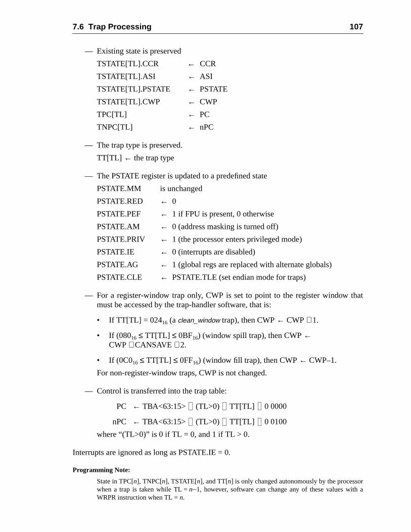
7.6 Trap Processing 107
hat
orh a
— Existing state is preserved
TSTATE[TL].CCR ← CCR
TSTATE[TL].ASI ← ASI
TSTATE[TL].PSTATE ← PSTATE
TSTATE[TL].CWP ← CWP
TPC[TL] ← PC
TNPC[TL] ← nPC
— The trap type is preserved.
TT[TL] ← the trap type
— The PSTATE register is updated to a predefined state
PSTATE.MM is unchanged
PSTATE.RED ← 0
PSTATE.PEF ← 1 if FPU is present, 0 otherwise
PSTATE.AM ← 0 (address masking is turned off)
PSTATE.PRIV ← 1 (the processor enters privileged mode)
PSTATE.IE ← 0 (interrupts are disabled)
PSTATE.AG ← 1 (global regs are replaced with alternate globals)
PSTATE.CLE ← PSTATE.TLE (set endian mode for traps)
— For a register-window trap only, CWP is set to point to the register window tmust be accessed by the trap-handler software, that is:
• If TT[TL] = 02416 (aclean_window trap), then CWP← CWP+ 1.
• If (08016 ≤ TT[TL] ≤ 0BF16) (window spill trap), then CWP←CWP+ CANSAVE + 2.
• If (0C016 ≤ TT[TL] ≤ 0FF16) (window fill trap), then CWP← CWP–1.
For non-register-window traps, CWP is not changed.
— Control is transferred into the trap table:
PC ← TBA<63:15> (TL>0) TT[TL] 0 0000
nPC ← TBA<63:15> (TL>0) TT[TL] 0 0100
where “(TL>0)” is 0 if TL = 0, and 1 if TL > 0.
Interrupts are ignored as long as PSTATE.IE = 0.
Programming Note:
State in TPC[n], TNPC[n], TSTATE[n], and TT[n] is only changed autonomously by the processwhen a trap is taken while TL =n–1, however, software can change any of these values witWRPR instruction when TL =n.
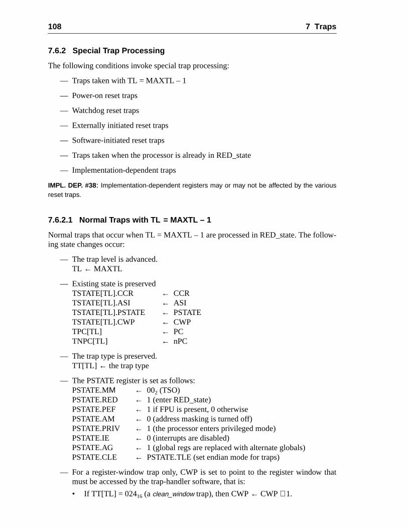
108 7 Traps
ow-
hat
7.6.2 Special Trap Processing
The following conditions invoke special trap processing:
— Traps taken with TL = MAXTL – 1
— Power-on reset traps
— Watchdog reset traps
— Externally initiated reset traps
— Software-initiated reset traps
— Traps taken when the processor is already in RED_state
— Implementation-dependent traps
IMPL. DEP. #38: Implementation-dependent registers may or may not be affected by the variousreset traps.
7.6.2.1 Normal Traps with TL = MAXTL – 1
Normal traps that occur when TL = MAXTL – 1 are processed in RED_state. The folling state changes occur:
— The trap level is advanced.TL ← MAXTL
— Existing state is preservedTSTATE[TL].CCR ← CCRTSTATE[TL].ASI ← ASITSTATE[TL].PSTATE ← PSTATETSTATE[TL].CWP ← CWPTPC[TL] ← PCTNPC[TL] ← nPC
— The trap type is preserved.TT[TL] ← the trap type
— The PSTATE register is set as follows:PSTATE.MΜ ← 002 (TSO)PSTATE.RED ← 1 (enter RED_state)PSTATE.PEF ← 1 if FPU is present, 0 otherwisePSTATE.AM ← 0 (address masking is turned off)PSTATE.PRIV ← 1 (the processor enters privileged mode)PSTATE.IE ← 0 (interrupts are disabled)PSTATE.AG ← 1 (global regs are replaced with alternate globals)PSTATE.CLE ← PSTATE.TLE (set endian mode for traps)
— For a register-window trap only, CWP is set to point to the register window tmust be accessed by the trap-handler software, that is:
• If TT[TL] = 02416 (aclean_window trap), then CWP← CWP+ 1.
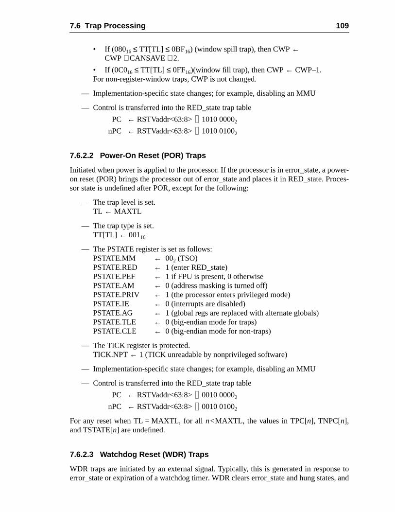
7.6 Trap Processing 109
ower-roces-
se tos, and
• If (08016 ≤ TT[TL] ≤ 0BF16) (window spill trap), then CWP←CWP+ CANSAVE + 2.
• If (0C016 ≤ TT[TL] ≤ 0FF16)(window fill trap), then CWP← CWP–1.For non-register-window traps, CWP is not changed.
— Implementation-specific state changes; for example, disabling an MMU
— Control is transferred into the RED_state trap table
PC ← RSTVaddr<63:8> 1010 00002
nPC ← RSTVaddr<63:8> 1010 01002
7.6.2.2 Power-On Reset (POR) Traps
Initiated when power is applied to the processor. If the processor is in error_state, a pon reset (POR) brings the processor out of error_state and places it in RED_state. Psor state is undefined after POR, except for the following:
— The trap level is set.TL ← MAXTL
— The trap type is set.TT[TL] ← 00116
— The PSTATE register is set as follows:PSTATE.MM ← 002 (TSO)PSTATE.RED ← 1 (enter RED_state)PSTATE.PEF ← 1 if FPU is present, 0 otherwisePSTATE.AM ← 0 (address masking is turned off)PSTATE.PRIV ← 1 (the processor enters privileged mode)PSTATE.IE ← 0 (interrupts are disabled)PSTATE.AG ← 1 (global regs are replaced with alternate globals)PSTATE.TLE ← 0 (big-endian mode for traps)PSTATE.CLE ← 0 (big-endian mode for non-traps)
— The TICK register is protected.TICK.NPT ← 1 (TICK unreadable by nonprivileged software)
— Implementation-specific state changes; for example, disabling an MMU
— Control is transferred into the RED_state trap table
PC ← RSTVaddr<63:8> 0010 00002
nPC ← RSTVaddr<63:8> 0010 01002
For any reset when TL = MAXTL, for alln<MAXTL, the values in TPC[n], TNPC[n],and TSTATE[n] are undefined.
7.6.2.3 Watchdog Reset (WDR) Traps
WDR traps are initiated by an external signal. Typically, this is generated in responerror_state or expiration of a watchdog timer. WDR clears error_state and hung state
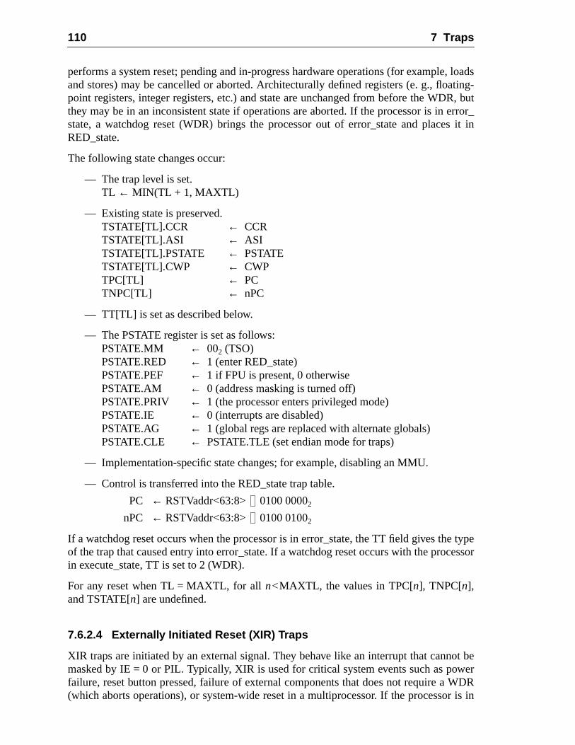
110 7 Traps
, loadsating-R, buterror_s it in
typeessor
ot bewerWDRr is in
performs a system reset; pending and in-progress hardware operations (for exampleand stores) may be cancelled or aborted. Architecturally defined registers (e. g., flopoint registers, integer registers, etc.) and state are unchanged from before the WDthey may be in an inconsistent state if operations are aborted. If the processor is instate, a watchdog reset (WDR) brings the processor out of error_state and placeRED_state.
The following state changes occur:
— The trap level is set.TL ← MIN(TL + 1, MAXTL)
— Existing state is preserved.TSTATE[TL].CCR ← CCRTSTATE[TL].ASI ← ASITSTATE[TL].PSTATE ← PSTATETSTATE[TL].CWP ← CWPTPC[TL] ← PCTNPC[TL] ← nPC
— TT[TL] is set as described below.
— The PSTATE register is set as follows:PSTATE.MM ← 002 (TSO)PSTATE.RED ← 1 (enter RED_state)PSTATE.PEF ← 1 if FPU is present, 0 otherwisePSTATE.AM ← 0 (address masking is turned off)PSTATE.PRIV ← 1 (the processor enters privileged mode)PSTATE.IE ← 0 (interrupts are disabled)PSTATE.AG ← 1 (global regs are replaced with alternate globals)PSTATE.CLE ← PSTATE.TLE (set endian mode for traps)
— Implementation-specific state changes; for example, disabling an MMU.
— Control is transferred into the RED_state trap table.
PC ← RSTVaddr<63:8> 0100 00002
nPC ← RSTVaddr<63:8> 0100 01002
If a watchdog reset occurs when the processor is in error_state, the TT field gives theof the trap that caused entry into error_state. If a watchdog reset occurs with the procin execute_state, TT is set to 2 (WDR).
For any reset when TL = MAXTL, for alln<MAXTL, the values in TPC[n], TNPC[n],and TSTATE[n] are undefined.
7.6.2.4 Externally Initiated Reset (XIR) Traps
XIR traps are initiated by an external signal. They behave like an interrupt that cannmasked by IE = 0 or PIL. Typically, XIR is used for critical system events such as pofailure, reset button pressed, failure of external components that does not require a(which aborts operations), or system-wide reset in a multiprocessor. If the processo
7.6 Trap Processing 111
e and
_statetate
ware
error_state, an externally initiated reset (XIR) brings the processor out of error_statplaces it in RED_state.
The following state changes occur:
— The trap level is set.TL ← MIN(TL + 1, MAXTL)
— Existing state is preserved.TSTATE[TL].CCR ← CCRTSTATE[TL].ASI ← ASITSTATE[TL].PSTATE ← PSTATETSTATE[TL].CWP ← CWPTPC[TL] ← PCTNPC[TL] ← nPC
— TT[TL] is set as described below.
— The PSTATE register is set as follows:PSTATE.MM ← 002 (TSO)PSTATE.RED ← 1 (enter RED_state)PSTATE.PEF ← 1 if FPU is present, 0 otherwisePSTATE.AM ← 0 (address masking is turned off)PSTATE.PRIV ← 1 (the processor enters privileged mode)PSTATE.IE ← 0 (interrupts are disabled)PSTATE.AG ← 1 (global regs are replaced with alternate globals)PSTATE.CLE ← PSTATE.TLE (set endian mode for traps)
— Implementation-specific state changes; for example, disabling an MMU.
— Control is transferred into the RED_state trap table.
PC ← RSTVaddr<63:8> 0110 00002
nPC ← RSTVaddr<63:8> 0110 01002
TT is set in the same manner as for watchdog reset. If the processor is in executewhen the externally initiated reset (XIR) occurs, TT = 3. If the processor is in error_swhen the XIR occurs, TT identifies the exception that caused entry into error_state.
For any reset when TL = MAXTL, for alln<MAXTL, the values in TPC[n], TNPC[n],and TSTATE[n] are undefined.
7.6.2.5 Software-Initiated Reset (SIR) Traps
SIR traps are initiated by executing an SIR instruction. This is used by supervisor softas a panic operation, or a meta-supervisor trap.
The following state changes occur:
— If TL = MAXTL, then enter error_state. Otherwise, do the following:
— The trap level is set.TL ← TL + 1
112 7 Traps
sed in
— Existing state is preservedTSTATE[TL].CCR ← CCRTSTATE[TL].ASI ← ASITSTATE[TL].PSTATE ← PSTATETSTATE[TL].CWP ← CWPTPC[TL] ← PCTNPC[TL] ← nPC
— The trap type is set.TT[TL] ← 0416
— The PSTATE register is set as follows:PSTATE.MM ← 002 (TSO)PSTATE.RED ← 1 (enter RED_state)PSTATE.PEF ← 1 if FPU is present, 0 otherwisePSTATE.AM ← 0 (address masking is turned off)PSTATE.PRIV ← 1 (the processor enters privileged mode)PSTATE.IE ← 0 (interrupts are disabled)PSTATE.AG ← 1 (global regs are replaced with alternate globals)PSTATE.CLE ← PSTATE.TLE (set endian mode for traps)
— Implementation-specific state changes; for example, disabling an MMU.
— Control is transferred into the RED_state trap table
PC ← RSTVaddr<63:8> 1000 00002
nPC ← RSTVaddr<63:8> 1000 01002
For any reset when TL = MAXTL, for alln < MAXTL, the values in TPC[n], TNPC[n],and TSTATE[n] are undefined.
7.6.2.6 Normal Traps When the Processor is in RED_state
Normal traps taken when the processor is already in RED_state are also procesRED_state, unless TL = MAXTL, in which case the processor enters error_state.
The processor state shall be set as follows:
— The trap level is set.TL ← TL + 1
— Existing state is preserved.TSTATE[TL].CCR ← CCRTSTATE[TL].ASI ← ASITSTATE[TL].PSTATE ← PSTATETSTATE[TL].CWP ← CWPTPC[TL] ← PCTNPC[TL] ← nPC
— The trap type is preserved.TT[TL] ← trap type
7.7 Exception and Interrupt Descriptions 113
hat
nd thespond-
excep-ni-
errorrror
on or
— The PSTATE register is set as follows:PSTATE.MM ← 002 (TSO)PSTATE.RED ← 1 (enter RED_state)PSTATE.PEF ← 1 if FPU is present, 0 otherwisePSTATE.AM ← 0 (address masking is turned off)PSTATE.PRIV ← 1 (the processor enters privileged mode)PSTATE.IE ← 0 (interrupts are disabled)PSTATE.AG ← 1 (global regs are replaced with alternate globals)PSTATE.CLE ← PSTATE.TLE (set endian mode for traps)
— For a register-window trap only, CWP is set to point to the register window tmust be accessed by the trap-handler software, that is:
• If TT[TL] = 02416 (aclean_window trap), then CWP← CWP+ 1.
• If (08016 ≤ TT[TL] ≤ 0BF16) (window spill trap), thenCWP← CWP+ CANSAVE + 2.
• If (0C016 ≤ TT[TL] ≤ 0FF16) (window fill trap), then CWP← CWP – 1.For non-register-window traps, CWP is not changed.
— Implementation-specific state changes; for example, disabling an MMU
— Control is transferred into the RED_state trap table
PC ← RSTVaddr<63:8> 1010 00002
nPC ← RSTVaddr<63:8> 1010 01002
7.6.2.7 Implementation-Dependent Traps
The operation of the processor forimplementation_dependent_exception_n traps is imple-mentation-dependent (impl. dep. #35).
7.7 Exception and Interrupt Descriptions
The following paragraphs describe the various exceptions and interrupt requests aconditions that cause them. Each exception and interrupt request describes the correing trap type as defined by the trap model. An open bullet ‘❍’ identifies optional and pos-sibly implementation-dependent traps; traps marked with a closed bullet ‘●’ aremandatory. Each trap is marked as precise, deferred, disrupting, or reset. Exampletion conditions are included for each exception type. Appendix A, “Instruction Defitions,” enumerates which traps can be generated by each instruction.
❍ async_data_error [tt = 04016] (Disrupting)
An asynchronous data error occurred on a data access. Examples: an ECCoccurred while writing data from a cache store buffer to memory, or an ECC eoccurred on an MMU hardware table walk. When anasync_data_error occurs, theTPC and TNPC stacked by the trap are not necessarily related to the instructidata access that caused the error; that is,async_data_error causes a disrupting trap.
114 7 Traps
dataed.
r
(foremory
hat a
le, aation
that
ch asr sys-
gis-
ting-, or
V8 Compatibility Note:The SPARC-V9async_data_error exception supersedes the less general SPARC-V8data_store_error exception.
❍ clean_window [tt = 02416..02716] (Precise)A SAVE instruction discovered that the window about to be used containsfrom another address space; the window must be cleaned before it can be us
IMPL. DEP. #102: An implementation may choose either to implement automatic cleaningof register windows in hardware, or to generate a clean_window trap, when needed, sothat window(s) can be cleaned by software. If an implementation chooses the latteoption, then support for this trap type is mandatory.
❍ data_access_error [tt = 03216] (Precise, Deferred, or Disrupting)A catastrophic error exception occurred on a data access from/to memoryexample, a parity error on a data cache access, or an uncorrectable ECC merror) (impl. dep. #31).
● data_access_exception [tt = 03016] (Precise or Deferred)An exception occurred on a data access. For example, an MMU indicated tpage was invalid or protected (impl. dep. #33).
❍ data_access_MMU_miss [tt = 03116] (Precise or Deferred)A miss in an MMU occurred on a data access from/to memory. For examppage descriptor cache or translation lookaside buffer did not contain a translfor the virtual address. (impl. dep. #33)
❍ data_access_protection [tt = 03316] (Precise or Deferred)A protection fault occurred on a data access; for example, an MMU indicatedthe page was write-protected (impl. dep. #33).
● division_by_zero [tt = 02816] (Precise or Deferred)An integer divide instruction attempted to divide by zero (impl. dep. #33).
❍ externally_initiated_reset [tt = 00316] (Reset)An external signal was asserted. This trap is used for catastrophic events supower failure, reset button pressed, and system-wide reset in multiprocessotems.
● fill_n_normal [tt = 0C016..0DF16] (Precise)
● fill_n_other [tt = 0E016..0FF16] (Precise)A RESTORE or RETURN instruction has determined that the contents of a reter window must be restored from memory.
V8 Compatibility Note:The SPARC-V9 fill_n_* exceptions supersede the SPARC-V8window_underflow exception.
● fp_disabled [tt = 02016] (Precise)An attempt was made to execute an FPop, a floating-point branch, or a floapoint load/store instruction while an FPU was not present, PSTATE.PEF = 0FPRS.FEF = 0.
7.7 Exception and Interrupt Descriptions 115
trap
was ae is
e, anat
tions
le, a
ated
ple,33)
par-
d
ressen-sup-ss is
❍ fp_exception_ieee_754 [tt = 02116] (Precise or Deferred (impl. dep. #23))An FPop instruction generated an IEEE_754_exception and its correspondingenable mask (TEM) bit was 1. The floating-point exception type,IEEE_754_excep-tion, is encoded in the FSR.ftt, and specificIEEE_754_exception information isencoded in FSR.cexc.
❍ fp_exception_other [tt = 02216] (Precise or Deferred (impl. dep. #23))An FPop instruction generated an exception other than anIEEE_754_exception. Forexample, the FPop is unimplemented, or the FPop did not complete, or theresequence or hardware error in the FPU. The floating-point exception typencoded in the FSR’sftt field.
● illegal_instruction [tt = 01016] (Precise or Deferred)An attempt was made to execute an instruction with an unimplemented opcodILLTRAP instruction, an instruction with invalid field usage, or an instruction thwould result in illegal processor state. Note that unimplemented FPop instrucgeneratefp_exception_other traps.
❍ implementation_dependent_exception_n [tt = 06016..07F16] (Pre, Def, or Dis)These exceptions are implementation-dependent (impl. dep. #35).
❍ instruction_access_error [tt = 00A16] (Precise, Deferred, or Disrupting)A catastrophic error exception occurred on an instruction access. For exampparity error on an instruction cache access (impl. dep. #31).
● instruction_access_exception [tt = 00816] (Precise)An exception occurred on an instruction access. For example, an MMU indicthat the page was invalid or not executable.
❍ instruction_access_MMU_miss [tt = 00916] (Precise, Deferred, or Disrupting)A miss in an MMU occurred on an instruction access from memory. For exama PDC or TLB did not contain a translation for the virtual address. (impl. dep. #
❍ internal_processor_error [tt = 02916] (Precise, Deferred, or Disrupting)A catastrophic error exception occurred in the main processor. For example, aity or uncorrectable ECC error on an internal register or bus (impl. dep. #31).
V8 Compatibility Note:The SPARC-V9internal_processor_error exception supersedes the less general SPARC-V8r_register_access_error exception.
● interrupt_level_n [tt = 04116..04F16] (Disrupting)An interrupt request level ofn was presented to the IU, while PSTATE.IE = 1 an(interrupt request level > PIL).
❍ LDDF_mem_address_not_aligned [tt = 03516] (Precise)An attempt was made to execute an LDDF instruction and the effective addwas word-aligned but not doubleword-aligned. Use of this exception is implemtation-dependent (impl. dep. #109). A separate trap entry for this exceptionports fast software emulation of the LDDF instruction when the effective addreword-aligned but not doubleword-aligned. See A.25, “Load Floating-Point.”
116 7 Traps
ressnta-portss is
ignedon-
from
= 0.h itsster
= 0.
o
lows
ster
s wasnta-portss is
s wasion-
❍ LDQF_mem_address_not_aligned [tt = 03816] (Precise)An attempt was made to execute an LDQF instruction and the effective addwas word-aligned but not quadword-aligned. Use of this exception is implemetion-dependent (impl. dep. #111). A separate trap entry for this exception supfast software emulation of the LDQF instruction when the effective addresword-aligned but not quadword-aligned. See A.25, “Load Floating-Point.”
● mem_address_not_aligned [tt = 03416] (Precise or Deferred)A load/store instruction generated a memory address that was not properly alaccording to the instruction, or a JMPL or RETURN instruction generated a nword-aligned address (impl. dep. #33).
● power_on_reset [tt = 00116] (Reset)An external signal was asserted. This trap isused to bring a system reliablythe power-off to the power-on state.
● privileged_action [tt = 03716] (Precise)An action defined to be privileged has been attempted while PSTATE.PRIVExamples: a data access by nonprivileged software using an ASI value witmost significant bit = 0 (a restricted ASI), or an attempt to read the TICK regiby nonprivileged software when TICK.NPT = 1.
● privileged_opcode [tt = 01116] (Precise)An attempt was made to execute a privileged instruction while PSTATE.PRIV
V8 Compatibility Note:This trap type is identical to the SPARC-V8privileged_instruction trap. The name was changed tdistinguish it from the newprivileged_action trap type.
● software_initiated_reset [tt = 00416] (Reset)Caused by the execution of the SIR, Software-Initiated Reset, instruction. It alsystem software to reset the processor.
● spill_n_normal [tt = 08016..09F16] (Precise)
● spill_n_other [tt = 0A016..0BF16] (Precise)A SAVE or FLUSHW instruction has determined that the contents of a regiwindow must be saved to memory.
V8 Compatibility Note:The SPARC-V9 spill_n_* exceptions supersede the SPARC-V8window_overflow exception.
❍ STDF_mem_address_not_aligned [tt = 03616] (Precise)An attempt was made to execute an STDF instruction and the effective addresword-aligned but not doubleword-aligned. Use of this exception is implemetion-dependent (impl. dep. #110). A separate trap entry for this exception supfast software emulation of the STDF instruction when the effective addresword-aligned but not doubleword-aligned. See A.52, “Store Floating-Point.”
❍ STQF_mem_address_not_aligned [tt = 03916] (Precise)An attempt was made to execute an STQF instruction and the effective addresword-aligned but not quadword-aligned. Use of this exception is implementat
7.7 Exception and Interrupt Descriptions 117
s fastord-
h-zero.
d in
d in
k cre-me. InED_
dependent (impl. dep. #112). A separate trap entry for this exception supportsoftware emulation of the STQF instruction when the effective address is waligned but not quadword-aligned. See A.52, “Store Floating-Point.”
● tag_overflow [tt = 02316] (Precise)A TADDccTV or TSUBccTV instruction was executed, and either 32-bit aritmetic overflow occurred or at least one of the tag bits of the operands was non
● trap_instruction [tt = 10016..17F16] (Precise)A Tcc instruction was executed and the trap condition evaluated to TRUE.
❍ unimplemented_LDD [tt = 01216] (Precise)An attempt was made to execute an LDD instruction, which is not implementehardware on this implementation (impl. dep. #107).
❍ unimplemented_STD [tt = 01316] (Precise)An attempt was made to execute an STD instruction which is not implementehardware on this implementation (impl. dep. #108).
● watchdog_reset [tt = 00216] (Precise)An external signal was asserted. This trap exists to break a system deadlocated when an expected external event does not happen within the expected tisimple systems it is also used to bring a system out of error_state, through Rstate, and ultimately back to execute_state.
All other trap types are reserved.

118 7 Traps
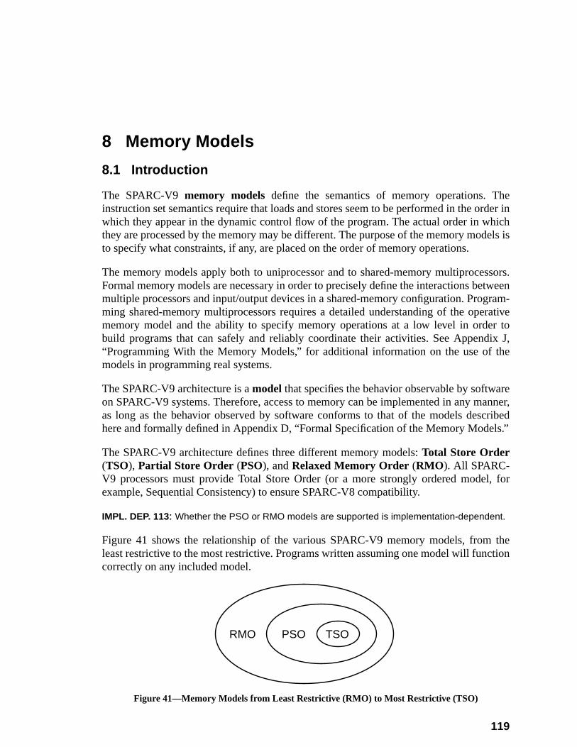
herder inhichdels is
ssors.tweengram-rativer toix J,he
reanner,cribedls.”
l, for
thection
8 Memory Models
8.1 Introduction
The SPARC-V9memory models define the semantics of memory operations. Tinstruction set semantics require that loads and stores seem to be performed in the owhich they appear in the dynamic control flow of the program. The actual order in wthey are processed by the memory may be different. The purpose of the memory moto specify what constraints, if any, are placed on the order of memory operations.
The memory models apply both to uniprocessor and to shared-memory multiproceFormal memory models are necessary in order to precisely define the interactions bemultiple processors and input/output devices in a shared-memory configuration. Proming shared-memory multiprocessors requires a detailed understanding of the opememory model and the ability to specify memory operations at a low level in ordebuild programs that can safely and reliably coordinate their activities. See Append“Programming With the Memory Models,” for additional information on the use of tmodels in programming real systems.
The SPARC-V9 architecture is amodel that specifies the behavior observable by softwaon SPARC-V9 systems. Therefore, access to memory can be implemented in any mas long as the behavior observed by software conforms to that of the models deshere and formally defined in Appendix D, “Formal Specification of the Memory Mode
The SPARC-V9 architecture defines three different memory models:Total Store Order(TSO), Partial Store Order (PSO), andRelaxed Memory Order (RMO ). All SPARC-V9 processors must provide Total Store Order (or a more strongly ordered modeexample, Sequential Consistency) to ensure SPARC-V8 compatibility.
IMPL. DEP. 113: Whether the PSO or RMO models are supported is implementation-dependent.
Figure 41 shows the relationship of the various SPARC-V9 memory models, fromleast restrictive to the most restrictive. Programs written assuming one model will funcorrectly on any included model.
Figure 41—Memory Models from Least Restrictive (RMO) to Most Restrictive (TSO)
RMO PSO TSO
119
120 8 Memory Models
x D,onodels
em-ttendel,uling
ipro-aker
gentialoads,l ordersors.an an-V9ly on
tionsan
m-dressest mem-
to beonsis-ddress.
luere, orxcept
andffects
SPARC-V9 provides multiple memory models so that:
— Implementations can schedule memory operations for high performance.
— Programmers can create synchronization primitives using shared memory.
These models are described informally in this subsection and formally in Appendi“Formal Specification of the Memory Models.” If there is a conflict in interpretatibetween the informal description provided here and the formal models, the formal msupersede the informal description.
There is no preferred memory model for SPARC-V9. Programs written for Relaxed Mory Order will work in Partial Store Order and Total Store Order as well. Programs wrifor Partial Store Order will work in Total Store Order. Programs written for a weak mosuch as RMO, may execute more quickly, since the model exposes more schedopportunities, but may also require extra instructions to ensure synchronization. Multcessor programs written for a stronger model will behave unpredictably if run in a wemodel.
Machines that implementsequential consistency(also called strong ordering or stronconsistency) automatically support programs written for TSO, PSO, and RMO. Sequconsistency is not a SPARC-V9 memory model. In sequential consistency, the lstores, and atomic load-stores of all processors are performed by memory in a seriathat conforms to the order in which these instructions are issued by individual procesA machine that implements sequential consistency may deliver lower performance thequivalent machine that implements a weaker model. Although particular SPARCimplementations may support sequential consistency, portable software must not rehaving this model available.
8.2 Memory, Real Memory, and I/O Locations
Memory is the collection of locations accessed by the load and store instruc(described in Appendix A, “Instruction Definitions”). Each location is identified byaddress consisting of two elements: anaddress space identifier(ASI), which identifies anaddress space, and a 64-bitaddress,which is a byte offset into that address space. Meory addresses may be interpreted by the memory subsystem to be either physical ador virtual addresses; addresses may be remapped and values cached, provided thaory properties are preserved transparently and coherency is maintained.
When two or more data addresses refer to the same datum, the address is saidaliased. In this case, the processor and memory system must cooperate to maintain ctency; that is, a store to an aliased address must change all values aliased to that a
Memory addresses identify either real memory or I/O locations.
Real memorystores information without side effects. A load operation returns the vamost recently stored. Operations are side-effect-free in the sense that a load, stoatomic load-store to a location in real memory has no program-observable effect, eupon that location.
I/O locations may not behave like memory and may have side effects. Load, store,atomic load-store operations performed on I/O locations may have observable side e
8.3 Addressing and Alternate Address Spaces 121
ationsr inreal
sses ofdep.
s, as
fer-aints.anteeectedansac-
nsurens areoper-
flag bit), orress
ASI)ressed,cludeword6-bytelign-ction
read orrds,to the
and loads may not return the value most recently stored. The value semantics of operon I/O locations arenot defined by the memory models, but the constraints on the ordewhich operations are performed is the same as it would be if the I/O locations werememory. The storage properties, contents, semantics, ASI assignments, and addreI/O registers are implementation-dependent (impl. dep. #6) (impl. dep. #7) (impl.#123).
IMPL. DEP. #118: The manner in which I/O locations are identified is implementation-dependent.
See F.3.2, “Attributes the MMU Associates with Each Mapping,” for example.
IMPL. DEP #120: The coherence and atomicity of memory operations between processors andI/O DMA memory accesses are implementation-dependent.
V8 Compatibility Note:
Operations to I/O locations arenot guaranteed to be sequentially consistent between themselvethey are in SPARC-V8.
SPARC-V9 does not distinguish real memory from I/O locations in terms of ordering. All reences, both to I/O locations and real memory, conform to the memory model’s order constrReferences to I/O locations may need to be interspersed with MEMBAR instructions to guarthe desired ordering. Loads following stores to locations with side effects may return unexpresults due to lookaside into the processor’s store buffer, which may subsume the memory trtion. This can be avoided by using a MEMBAR#LookAside .
Systems supporting SPARC-V8 applications that use memory mapped I/O locations must ethat SPARC-V8 sequential consistency of I/O locations can be maintained when those locatioreferenced by a SPARC-V8 application. The MMU either must enforce such consistency or coate with system software and/or the processor to provide it.
IMPL. DEP #121: An implementation may choose to identify certain addresses and use an imple-mentation-dependent memory model for references to them.
For example, an implementation might choose to process addresses tagged with ain the memory management unit (see Appendix F, “SPARC-V9 MMU Requirements”to treat those that utilize a particular ASI (see 8.3, “Addressing and Alternate AddSpaces,” below) as using a sequentially consistent model.
8.3 Addressing and Alternate Address Spaces
An address in SPARC-V9 is a tuple consisting of an 8-bit address space identifier (and a 64-bit byte-address offset in the specified address space. Memory is byte-addwith halfword accesses aligned on 2-byte boundaries, word accesses (which ininstruction fetches) aligned on 4-byte boundaries, extended-word and doubleaccesses aligned on 8-byte boundaries, and quadword quantities aligned on 1boundaries. With the possible exception of the cases described in 6.3.1.1, “Memory Ament Restrictions,” an improperly aligned address in a load, store, or load-store instrualways causes a trap to occur. The largest datum that is guaranteed to be atomicallywritten is an aligned doubleword. Also, memory references to different bytes, halfwoand words in a given doubleword are treated for ordering purposes as referencessame location. Thus, the unit of ordering for memory is a doubleword.
122 8 Memory Models
t dou-lwaysn oper-rmineARC-ay be
serve
offset
thedian-
e, or
ftwares, or to
fullyrallyduce
tions_
osen
r thesessing
useding.ss toeen
Programming Note:While the doubleword is the coherency unit for update, programmers should not assume thableword floating-point values are updated as a unit unless they are doubleword-aligned and aupdated using double-precision loads and stores. Some programs use pairs of single-precisioations to load and store double-precision floating-point values when the compiler cannot detethat they are doubleword-aligned. Also, while quad-precision operations are defined in the SPV9 architecture, the granularity of loads and stores for quad-precision floating-point values mword or doubleword.
The processor provides an address space identifier with every address. This ASI mayseveral purposes:
— To identify which of several distinguished address spaces the 64-bit addressis to be interpreted as addressing
— To provide additional access control and attribute information, for example,processing which is to be taken if an access fault occurs or to specify the enness of the reference
— To specify the address of an internal control register in the processor, cachmemory management hardware
The memory management hardware can associate an independent 264-byte memoryaddress space with each ASI. If this is done, it becomes possible to allow system soeasy access to the address space of the faulting program when processing exceptionimplement access to a client program’s memory space by a server program.
The architecturally specified ASIs are listed in table 14 on page 74. ASIs need not bedecoded by the hardware (impl. dep. #30). In particular, specifying an architectuundefined ASI value in a memory reference instruction or in the ASI register may prounexpected implementation-dependent results.
When TL = 0, normal accesses by the processor to memory when fetching instrucand performing loads and stores implicitly specify ASI_PRIMARY or ASI_PRIMARYLITTLE, depending on the setting of the PSTATE.CLE bit.
IMPL. DEP. #124: When TL > 0, the implicit ASI for instruction fetches, loads, and stores is imple-mentation-dependent.
Implementation Note:Implementations that support the nucleus context should use ASI_NUCLEUS{_LITTLE}; ththat do not should use ASI_PRIMARY{_LITTLE}. See F.4.4, “Contexts,” for more informatioabout the nucleus context.
Accesses to other address spaces use the load/store alternate instructions. Foaccesses, the ASI is either contained in the instruction (for the register-register addremode) or taken from the ASI register (for register-immediate addressing).
ASIs are either unrestricted or restricted. An unrestricted ASI is one that may beindependent of the privilege level (PSTATE.PRIV) at which the processor is runnRestricted ASIs require that the processor be in privileged mode for a legal acceoccur. Restricted ASIs have their high-order bit equal to zero. The relationship betwprocessor state and ASI restriction is shown in table 13 on page 73.
8.4 The SPARC-V9 Memory Model 123
}e
strictednre-s a
heym so
han-.
urestionn non-a faultpear tornate
o(espe-cause
non-unde-
of acture.red
renceseen
ecu-
t, and
Several restricted ASIs must be provided: ASI_AS_IF_USER_PRIMARY{_LITTLEand ASI_AS_IF_USER_SECONDARY{_LITTLE}. The intent of these ASIs is to givsystem software efficient access to the memory space of a program.
The normal address space is primary address space, which is accessed by the unreASI_PRIMARY{_LITTLE}. The secondary address space, which is accessed by the ustricted ASI_SECONDARY{_LITTLE}, is provided to allow a server program to accesclient program’s address space.
ASI_PRIMARY_NOFAULT{_LITTLE} and ASI_SECONDARY_NOFAULT{_LIT-TLE} supportnonfaulting loads. These ASIs are aliased to ASI_PRIMARY{_LITTLE}and ASI_SECONDARY{_LITTLE}, respectively, and have exactly the same action. Tmay be used to color (that is, distinguish into classes) loads in the instruction streathat, in combination with a judicious mapping of low memory and a specialized trapdler, an optimizing compiler can move loads outside of conditional control structures
Programming Note:Nonfaulting loads allow optimizations that move loads ahead of conditional control structwhich guard their use; thus, they can minimize the effects of load latency by improving instrucscheduling. The semantics of nonfaulting load are the same as for any other load, except wherecoverable catastrophic faults occur (for example, address-out-of-range errors). When suchoccurs, it is ignored and the hardware and system software cooperate to make the load apcomplete normally, returning a zero result. The compiler’s optimizer generates load-alteinstructions with the ASI field or register set to ASI_PRIMARY_NOFAULT{_LITTLE} or ASI_SECONDARY_NOFAULT{_LITTLE} for those loads it determines should be nonfaulting. Tminimize unnecessary processing if a fault does occur, it is desirable to map low addressescially address zero) to a page of all zeros, so that references through a NULL pointer do notunnecessary traps.
Implementation Note:An implementation, through a combination of hardware and system software, must preventfaulting loads on memory locations that have side effects; otherwise, such accesses producefined results.
8.4 The SPARC-V9 Memory Model
The SPARC-V9 processor architecture specifies the organization and structureSPARC-V9 central processing unit, but does not specify a memory system architeAppendix F, “SPARC-V9 MMU Requirements,” summarizes the MMU support requiby a SPARC-V9 central processing unit.
The memory models specify the possible order relationships between memory-refeinstructions issued by a processor and the order and visibility of those instructions asby other processors. The memory model is intimately intertwined with the program extion model for instructions.
8.4.1 The SPARC-V9 Program Execution Model
The SPARC-V9 processor model consists of three units: an issue unit, a reorder unian execute unit, as shown in figure 42.
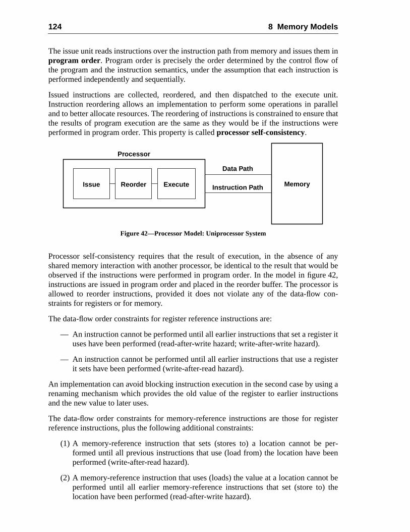
124 8 Memory Models
em inof
tion is
unit.allelre thatwere
f anyld be42,
sor ison-
er it
ister
ing ations
gister
per-een
ot bethe
The issue unit reads instructions over the instruction path from memory and issues thprogram order . Program order is precisely the order determined by the control flowthe program and the instruction semantics, under the assumption that each instrucperformed independently and sequentially.
Issued instructions are collected, reordered, and then dispatched to the executeInstruction reordering allows an implementation to perform some operations in parand to better allocate resources. The reordering of instructions is constrained to ensuthe results of program execution are the same as they would be if the instructionsperformed in program order. This property is calledprocessor self-consistency.
Figure 42—Processor Model: Uniprocessor System
Processor self-consistency requires that the result of execution, in the absence oshared memory interaction with another processor, be identical to the result that wouobserved if the instructions were performed in program order. In the model in figureinstructions are issued in program order and placed in the reorder buffer. The procesallowed to reorder instructions, provided it does not violate any of the data-flow cstraints for registers or for memory.
The data-flow order constraints for register reference instructions are:
— An instruction cannot be performed until all earlier instructions that set a registuses have been performed (read-after-write hazard; write-after-write hazard).
— An instruction cannot be performed until all earlier instructions that use a regit sets have been performed (write-after-read hazard).
An implementation can avoid blocking instruction execution in the second case by usrenaming mechanism which provides the old value of the register to earlier instrucand the new value to later uses.
The data-flow order constraints for memory-reference instructions are those for rereference instructions, plus the following additional constraints:
(1) A memory-reference instruction that sets (stores to) a location cannot beformed until all previous instructions that use (load from) the location have bperformed (write-after-read hazard).
(2) A memory-reference instruction that uses (loads) the value at a location cannperformed until all earlier memory-reference instructions that set (store to)location have been performed (read-after-write hazard).
Processor
Memory
Data Path
Instruction PathIssue Reorder Execute
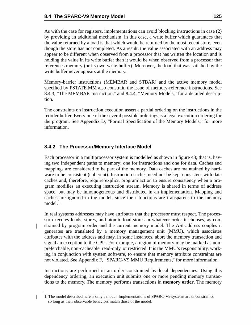
8.4 The SPARC-V9 Memory Model 125
e (2)that
, evenss mayand isthat
y the
del. Seeip-
in theg for
ore
, hav-s andhard-
h dataa pro-dressg andmory
proces-s con-les it
ciateson and
non-ork-s aren.
thisnsac-
ed
As with the case for registers, implementations can avoid blocking instructions in casby providing an additional mechanism, in this case, a write buffer which guaranteesthe value returned by a load is that which would be returned by the most recent storethough the store has not completed. As a result, the value associated with an addreappear to be different when observed from a processor that has written the locationholding the value in its write buffer than it would be when observed from a processorreferences memory (or its own write buffer). Moreover, the load that was satisfied bwrite buffer never appears at the memory.
Memory-barrier instructions (MEMBAR and STBAR) and the active memory mospecified by PSTATE.MM also constrain the issue of memory-reference instructions8.4.3, “The MEMBAR Instruction,” and 8.4.4, “Memory Models,” for a detailed descrtion.
The constraints on instruction execution assert a partial ordering on the instructionsreorder buffer. Every one of the several possible orderings is a legal execution orderinthe program. See Appendix D, “Formal Specification of the Memory Models,” for minformation.
8.4.2 The Processor/Memory Interface Model
Each processor in a multiprocessor system is modelled as shown in figure 43; that ising two independent paths to memory: one for instructions and one for data. Cachemappings are considered to be part of the memory. Data caches are maintained byware to be consistent (coherent). Instruction caches need not be kept consistent witcaches and, therefore, require explicit program action to ensure consistency whengram modifies an executing instruction stream. Memory is shared in terms of adspace, but may be inhomogeneous and distributed in an implementation. Mappincaches are ignored in the model, since their functions are transparent to the memodel.1
In real systems addresses may have attributes that the processor must respect. Thesor executes loads, stores, and atomic load-stores in whatever order it chooses, astrained by program order and the current memory model. The ASI-address coupgenerates are translated by a memory management unit (MMU), which assoattributes with the address and may, in some instances, abort the memory transactisignal an exception to the CPU. For example, a region of memory may be marked asprefetchable, non-cacheable, read-only, or restricted. It is the MMU’s responsibility, wing in conjunction with system software, to ensure that memory attribute constraintnot violated. See Appendix F, “SPARC-V9 MMU Requirements,” for more informatio
Instructions are performed in an order constrained by local dependencies. Usingdependency ordering, an execution unit submits one or more pending memory trations to the memory. The memory performs transactions inmemory order. The memory
1. The model described here is only a model. Implementations of SPARC-V9 systems are unconstrainso long as their observable behaviors match those of the model.
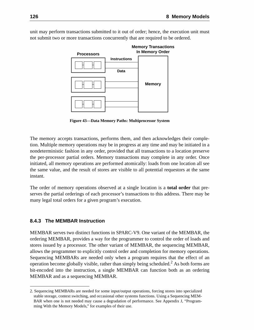
126 8 Memory Models
must
mple-in a
serveOncel seesame
may be
heandAR,
ons.of an
ring
dM-m-
unit may perform transactions submitted to it out of order; hence, the execution unitnot submit two or more transactions concurrently that are required to be ordered.
Figure 43—Data Memory Paths: Multiprocessor System
The memory accepts transactions, performs them, and then acknowledges their cotion. Multiple memory operations may be in progress at any time and may be initiatednondeterministic fashion in any order, provided that all transactions to a location prethe per-processor partial orders. Memory transactions may complete in any order.initiated, all memory operations are performed atomically: loads from one location althe same value, and the result of stores are visible to all potential requestors at theinstant.
The order of memory operations observed at a single location is atotal order that pre-serves the partial orderings of each processor’s transactions to this address. Theremany legal total orders for a given program’s execution.
8.4.3 The MEMBAR Instruction
MEMBAR serves two distinct functions in SPARC-V9. One variant of the MEMBAR, tordering MEMBAR, provides a way for the programmer to control the order of loadsstores issued by a processor. The other variant of MEMBAR, the sequencing MEMBallows the programmer to explicitly control order and completion for memory operatiSequencing MEMBARs are needed only when a program requires that the effectoperation become globally visible, rather than simply being scheduled.2 As both forms arebit-encoded into the instruction, a single MEMBAR can function both as an ordeMEMBAR and as a sequencing MEMBAR.
2. Sequencing MEMBARs are needed for some input/output operations, forcing stores into specializestable storage, context switching, and occasional other systems functions. Using a Sequencing MEBAR when one is not needed may cause a degradation of performance. See Appendix J, “Programing With the Memory Models,” for examples of their use.
Processors
Memory TransactionsIn Memory Order
Memory
Instructions
Data
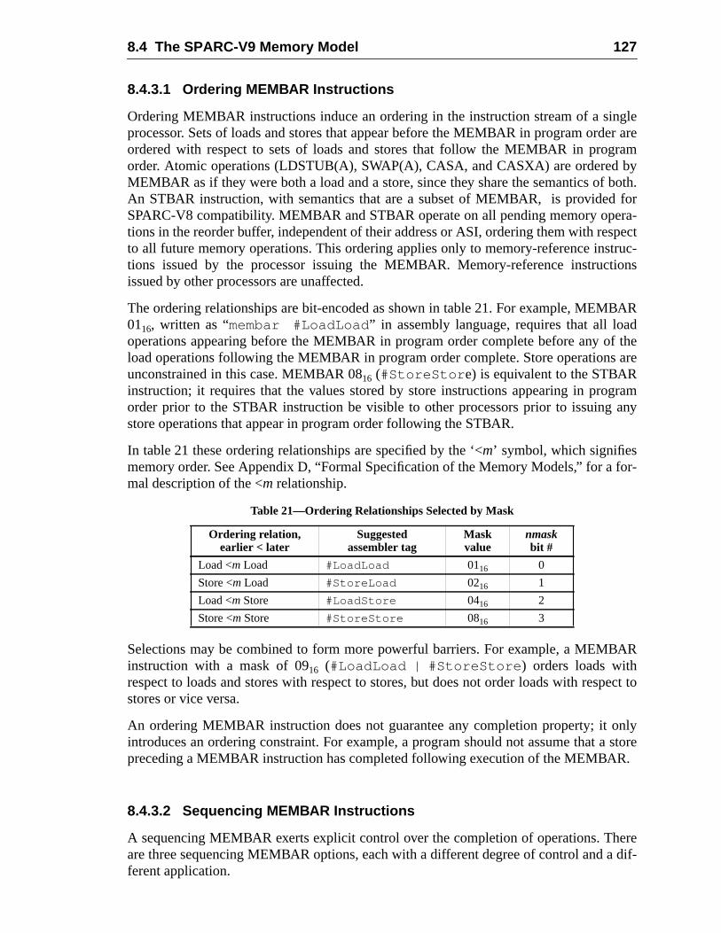
8.4 The SPARC-V9 Memory Model 127
gleer arerambyboth.forra-
specttruc-ions
BARdf theare
gramany
for-
AR
pect to
nlystore
R.
eredif-
8.4.3.1 Ordering MEMBAR Instructions
Ordering MEMBAR instructions induce an ordering in the instruction stream of a sinprocessor. Sets of loads and stores that appear before the MEMBAR in program ordordered with respect to sets of loads and stores that follow the MEMBAR in progorder. Atomic operations (LDSTUB(A), SWAP(A), CASA, and CASXA) are orderedMEMBAR as if they were both a load and a store, since they share the semantics ofAn STBAR instruction, with semantics that are a subset of MEMBAR, is providedSPARC-V8 compatibility. MEMBAR and STBAR operate on all pending memory opetions in the reorder buffer, independent of their address or ASI, ordering them with reto all future memory operations. This ordering applies only to memory-reference instions issued by the processor issuing the MEMBAR. Memory-reference instructissued by other processors are unaffected.
The ordering relationships are bit-encoded as shown in table 21. For example, MEM0116, written as “membar #LoadLoad ” in assembly language, requires that all loaoperations appearing before the MEMBAR in program order complete before any oload operations following the MEMBAR in program order complete. Store operationsunconstrained in this case. MEMBAR 0816 (#StoreStor e) is equivalent to the STBARinstruction; it requires that the values stored by store instructions appearing in proorder prior to the STBAR instruction be visible to other processors prior to issuingstore operations that appear in program order following the STBAR.
In table 21 these ordering relationships are specified by the ‘<m’ symbol, which signifiesmemory order. See Appendix D, “Formal Specification of the Memory Models,” for amal description of the <m relationship.
Selections may be combined to form more powerful barriers. For example, a MEMBinstruction with a mask of 0916 (#LoadLoad | #StoreStore ) orders loads withrespect to loads and stores with respect to stores, but does not order loads with resstores or vice versa.
An ordering MEMBAR instruction does not guarantee any completion property; it ointroduces an ordering constraint. For example, a program should not assume that apreceding a MEMBAR instruction has completed following execution of the MEMBA
8.4.3.2 Sequencing MEMBAR Instructions
A sequencing MEMBAR exerts explicit control over the completion of operations. Thare three sequencing MEMBAR options, each with a different degree of control and aferent application.
Table 21—Ordering Relationships Selected by Mask
Ordering relation,earlier < later
Suggestedassembler tag
Maskvalue
nmaskbit #
Load <m Load #LoadLoad 0116 0
Store <m Load #StoreLoad 0216 1
Load <m Store #LoadStore 0416 2
Store <m Store #StoreStore 0816 3
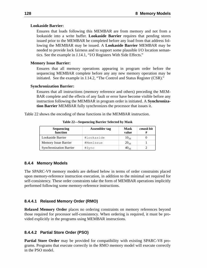
128 8 Memory Models
asfol-
man-
they be.”
EM-any
acedd forcitly
ondpro-
-ectly
Lookaside Barrier:Ensures that loads following this MEMBAR are from memory and not fromlookaside into a write buffer.Lookaside Barrier requires that pending storeissued prior to the MEMBAR be completed before any load from that addresslowing the MEMBAR may be issued. ALookaside Barrier MEMBAR may beneeded to provide lock fairness and to support some plausible I/O location setics. See the example in J.14.1, “I/O Registers With Side Effects.”
Memory Issue Barrier:Ensures that all memory operations appearing in program order beforesequencing MEMBAR complete before any any new memory operation mainitiated. See the example in J.14.2, “The Control and Status Register (CSR)
Synchronization Barrier:Ensures that all instructions (memory reference and others) preceding the MBAR complete and the effects of any fault or error have become visible beforeinstruction following the MEMBAR in program order is initiated. ASynchroniza-tion Barrier MEMBAR fully synchronizes the processor that issues it.
Table 22 shows the encoding of these functions in the MEMBAR instruction.
8.4.4 Memory Models
The SPARC-V9 memory models are defined below in terms of order constraints plupon memory-reference instruction execution, in addition to the minimal set requireself-consistency. These order constraints take the form of MEMBAR operations impliperformed following some memory-reference instructions.
8.4.4.1 Relaxed Memory Order (RMO)
Relaxed Memory Order places no ordering constraints on memory references beythose required for processor self-consistency. When ordering is required, it must bevided explicitly in the programs using MEMBAR instructions.
8.4.4.2 Partial Store Order (PSO)
Partial Store Order may be provided for compatibility with existing SPARC-V8 programs. Programs that execute correctly in the RMO memory model will execute corrin the PSO model.
Table 22—Sequencing Barrier Selected by Mask
Sequencingfunction
Assembler tag Maskvalue
cmaskbit#
Lookaside Barrier #Lookaside 1016 0
Memory Issue Barrier #MemIssue 2016 1
Synchronization Barrier #Sync 4016 2
8.4 The SPARC-V9 Memory Model 129
by a
ore
-n the
sk
sk
ask
.1.4,
tions
es of
The rules for PSO are:
— Loads are blocking and ordered with respect to earlier loads.
— Atomic load-stores are ordered with respect to loads.
Thus, PSO ensures that:
— Each load and atomic load-store instruction behaves as if it were followedMEMBAR with a mask value of 0516.
— Explicit MEMBAR instructions are required to order store and atomic load-stinstructions with respect to each other.
8.4.4.3 Total Store Order (TSO)
Total Store Order must be provided for compatibility with existing SPARC-V8 programs. Programs that execute correctly in either RMO or PSO will execute correctly iTSO model.
The rules for TSO are:
— Loads are blocking and ordered with respect to earlier loads.
— Stores are ordered with respect to stores.
— Atomic load-stores are ordered with respect to loads and stores.
Thus, TSO ensures that:
— Each load instruction behaves as if it were followed by a MEMBAR with a mavalue of 0516.
— Each store instruction behaves as if it were followed by a MEMBAR with a maof 0816.
— Each atomic load-store behaves as if it were followed by a MEMBAR with a mof 0D16.
8.4.5 Mode Control
The memory model is specified by the two-bit state in PSTATE.MM, described in 5.2“PSTATE_mem_model (MM).”
Writing a new value into PSTATE.MM causes subsequent memory reference instructo be performed with the order constraints of the specified memory model.
SPARC-V9 processors need not provide all three memory models; undefined valuPSTATE.MM have implementation-dependent effects.
IMPL. DEP. #119: The effect of writing an unimplemented memory mode designation intoPSTATE.MM is implementation-dependent.
130 8 Memory Models
-V8
ap is.MM
ructitives
emorythe
tionsr data
s areared noth as a
egisterwithera-oncere hasther
niza--freepare-se of
Implementation Note:
All SPARC-V9 implementations must provide TSO or a stronger model to maintain SPARCcompatibility. An implementation may provide PSO, RMO, or neither.
Except when a trap enters RED_state, PSTATE.MM is left unchanged when a trentered and the old value is stacked. When entering RED_state, the value of PSTATEis set to TSO.
8.4.6 Hardware Primitives for Mutual Exclusion
In addition to providing memory-ordering primitives that allow programmers to constmutual-exclusion mechanisms in software, SPARC-V9 provides three hardware primfor mutual exclusion:
— Compare and Swap (CASA, CASXA)
— Load Store Unsigned Byte (LDSTUB, LDSTUBA)
— Swap (SWAP, SWAPA)
Each of these instructions has the semantics of both a load and a store in all three mmodels. They are allatomic, in the sense that no other store can be performed betweenload and store elements of the instruction. All of the hardware mutual exclusion operaconform to the memory models and may require barrier instructions to ensure propevisibility.
When the hardware mutual-exclusion primitives address I/O locations, the resultimplementation-dependent (impl. dep. #123). In addition, the atomicity of hardwmutual-exclusion primitives is guaranteed only for processor memory references anwhen the memory location is simultaneously being addressed by an I/O device succhannel or DMA (impl. dep. #120).
8.4.6.1 Compare and Swap (CASA, CASXA)
Compare-and-swap is an atomic operation which compares a value in a processor rto a value in memory, and, if and only if they are equal, swaps the value in memorythe value in a second processor register. Both 32-bit (CASA) and 64-bit (CASXA) options are provided. The compare-and-swap operation is atomic in the sense thatbegun, no other processor can access the memory location specified until the compacompleted and the swap (if any) has also completed and is potentially visible to all oprocessors in the system.
Compare-and-swap is substantially more powerful than the other hardware synchrotion primitives. It has an infinite consensus number; that is, it can resolve, in a waitfashion, an infinite number of contending processes. Because of this property, comand-swap can be used to construct wait-free algorithms that do not require the ulocks. See Appendix J, “Programming With the Memory Models,” for examples.
8.4 The SPARC-V9 Memory Model 131
em-con-
P, itcesses
agesonsis-s aremorycache
d thecessortipro-uencecase,SHction
wordr anyto the
tes it
me-
stency
8.4.6.2 Swap (SWAP)
SWAP atomically exchanges the lower 32 bits in a processor register with a word in mory. Swap has a consensus number of two; that is, it cannot resolve more than twotending processes in a wait-free fashion.
8.4.6.3 Load Store Unsigned Byte (LDSTUB)
LDSTUB loads a byte value from memory to a register and writes the value FF16 into theaddressed byte atomically. LDSTUB is the classic test-and-set instruction. Like SWAhas a consensus number of two and so cannot resolve more than two contending proin a wait-free fashion.
8.4.7 Synchronizing Instruction and Data Memory
The SPARC-V9 memory models do not require that instruction and data memory imbe consistent at all times. The instruction and data memory images may become inctent if a program writes into the instruction stream. As a result, whenever instructionmodified by a program in a context where the data (that is, the instructions) in the meand the data cache hierarchy may be inconsistent with instructions in the instructionhierarchy, some special programmatic action must be taken.
The FLUSH instruction will ensure consistency between the instruction stream andata references across any local caches for a particular doubleword value in the proexecuting the FLUSH. It will ensure eventual consistency across all caches in a mulcessor system. The programmer must be careful to ensure that the modification seqis robust under multiple updates and concurrent execution. Since, in the generalloads and stores may be performed out of order, appropriate MEMBAR and FLUinstructions must be interspersed as needed to control the order in which the instrudata is mutated.
The FLUSH instruction ensures that subsequent instruction fetches from the doubletarget of the FLUSH by the processor executing the FLUSH appear to execute afteloads, stores, and atomic load-stores issued by the processor to that address priorFLUSH. FLUSH acts as a barrier for instruction fetches in the processor that execuand has the properties of a store with respect to MEMBAR operations.
FLUSH has no latency on the issuing processor; the modified instruction stream is imdiately available.3
IMPL. DEP. #122: The latency between the execution of FLUSH on one processor and the point atwhich the modified instructions have replaced outdated instructions in a multiprocessor is imple-mentation-dependent.
If all caches in a system (uniprocessor or multiprocessor) have a unified cache consiprotocol, FLUSH does nothing.
3. SPARC-V8 specified a five-instruction latency. Invalidation of instructions in execution in the instruc-tion cache is likely to force an instruction-cache fault.
132 8 Memory Models
deg-odifiedm,e dou-vali-
ations,r-call-ions,ap to
Use of FLUSH in a multiprocessor environment may cause unexpected performanceradation in some systems, because every processor that may have a copy of the mdata in its instruction cache must invalidate that data. In the worst case naive systeallprocessors must invalidate the data. The performance problem is compounded by thbleword granularity of the FLUSH, which must be observed even when the actual indation unit is larger, for example, a cache line.
Programming Note:Because FLUSH is designed to act on a doubleword, and because, on some implementFLUSH may trap to system software, it is recommended that system software provide a useable service routine for flushing arbitrarily sized regions of memory. On some implementatthis routine would issue a series of FLUSH instructions; on others, it might issue a single trsystem software that would then flush the entire region.
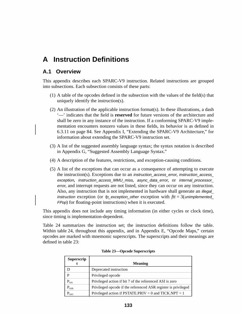
uped
that
ashdle-ed infor
ribed
ecute
tion.
e),
ble.taings are
A Instruction Definitions
A.1 Overview
This appendix describes each SPARC-V9 instruction. Related instructions are grointo subsections. Each subsection consists of these parts:
(1) A table of the opcodes defined in the subsection with the values of the field(s)uniquely identify the instruction(s).
(2) An illustration of the applicable instruction format(s). In these illustrations, a d‘—’ indicates that the field isreservedfor future versions of the architecture anshall be zero in any instance of the instruction. If a conforming SPARC-V9 impmentation encounters nonzero values in these fields, its behavior is as defin6.3.11 on page 84. See Appendix I, “Extending the SPARC-V9 Architecture,”information about extending the SPARC-V9 instruction set.
(3) A list of the suggested assembly language syntax; the syntax notation is descin Appendix G, “Suggested Assembly Language Syntax.”
(4) A description of the features, restrictions, and exception-causing conditions.
(5) A list of the exceptions that can occur as a consequence of attempting to exthe instruction(s). Exceptions due to aninstruction_access_error, instruction_access_exception, instruction_access_MMU_miss, async_data_error, or internal_processor_error, and interrupt requests are not listed, since they can occur on any instrucAlso, any instruction that is not implemented in hardware shall generate anillegal_instruction exception (orfp_exception_other exception withftt = 3(unimplemented_FPop) for floating-point instructions) when it is executed.
This appendix does not include any timing information (in either cycles or clock timsince timing is implementation-dependent.
Table 24 summarizes the instruction set; the instruction definitions follow the taWithin table 24, throughout this appendix, and in Appendix E, “Opcode Maps,” ceropcodes are marked with mnemonic superscripts. The superscripts and their meanindefined in table 23:
Table 23—Opcode Superscripts
Superscript Meaning
D Deprecated instruction
P Privileged opcode
PASI Privileged action if bit 7 of the referenced ASI is zero
PASR Privileged opcode if the referenced ASR register is privileged
PNPT Privileged action if PSTATE.PRIV = 0 and TICK.NPT = 1
133
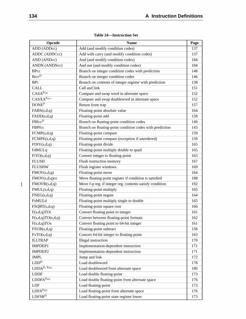
134 A Instruction Definitions
Table 24—Instruction Set
Opcode Name PageADD (ADDcc) Add (and modify condition codes) 137
ADDC (ADDCcc) Add with carry (and modify condition codes) 137
AND (ANDcc) And (and modify condition codes) 184
ANDN (ANDNcc) And not (and modify condition codes) 184
BPcc Branch on integer condition codes with prediction 148
BiccD Branch on integer condition codes 146
BPr Branch on contents of integer register with prediction 138
CALL Call and link 151
CASAPASI Compare and swap word in alternate space 152
CASXAPAS I Compare and swap doubleword in alternate space 152
DONEP Return from trap 157
FABS(s,d,q) Floating-point absolute value 164
FADD(s,d,q) Floating-point add 158
FBfccD Branch on floating-point condition codes 140
FBPfcc Branch on floating-point condition codes with prediction 143
FCMP(s,d,q) Floating-point compare 159
FCMPE(s,d,q) Floating-point compare (exception if unordered) 159
FDIV(s,d,q) Floating-point divide 165
FdMULq Floating-point multiply double to quad 165
FiTO(s,d,q) Convert integer to floating-point 163
FLUSH Flush instruction memory 167
FLUSHW Flush register windows 169
FMOV(s,d,q) Floating-point move 164
FMOV(s,d,q)cc Move floating-point register if condition is satisfied 188
FMOVR(s,d,q) Move f-p reg. if integer reg. contents satisfy condition 192
FMUL(s,d,q) Floating-point multiply 165
FNEG(s,d,q) Floating-point negate 164
FsMULd Floating-point multiply single to double 165
FSQRT(s,d,q) Floating-point square root 166
F(s,d,q)TOi Convert floating point to integer 161
F(s,d,q)TO(s,d,q) Convert between floating-point formats 162
F(s,d,q)TOx Convert floating point to 64-bit integer 161
FSUB(s,d,q) Floating-point subtract 158
FxTO(s,d,q) Convert 64-bit integer to floating-point 163
ILLTRAP Illegal instruction 170
IMPDEP1 Implementation-dependent instruction 171
IMPDEP2 Implementation-dependent instruction 171
JMPL Jump and link 172
LDDD Load doubleword 178
LDDAD, PASI Load doubleword from alternate space 180
LDDF Load double floating-point 173
LDDFAPASI Load double floating-point from alternate space 176
LDF Load floating-point 173
LDFAPASI Load floating-point from alternate space 176
LDFSRD Load floating-point state register lower 173
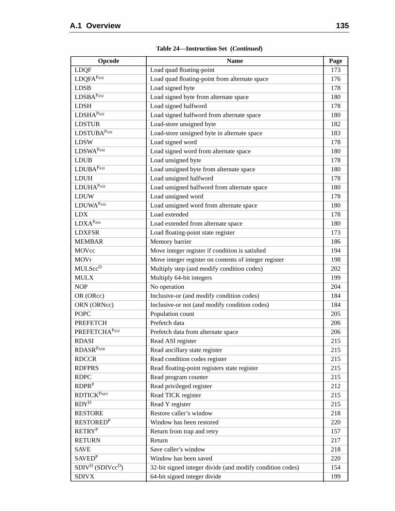
A.1 Overview 135
LDQF Load quad floating-point 173
LDQFAPASI Load quad floating-point from alternate space 176
LDSB Load signed byte 178
LDSBAPASI Load signed byte from alternate space 180
LDSH Load signed halfword 178
LDSHAPASI Load signed halfword from alternate space 180
LDSTUB Load-store unsigned byte 182
LDSTUBAPASI Load-store unsigned byte in alternate space 183
LDSW Load signed word 178
LDSWAPASI Load signed word from alternate space 180
LDUB Load unsigned byte 178
LDUBAPASI Load unsigned byte from alternate space 180
LDUH Load unsigned halfword 178
LDUHAPASI Load unsigned halfword from alternate space 180
LDUW Load unsigned word 178
LDUWAPASI Load unsigned word from alternate space 180
LDX Load extended 178
LDXA PASI Load extended from alternate space 180
LDXFSR Load floating-point state register 173
MEMBAR Memory barrier 186
MOVcc Move integer register if condition is satisfied 194
MOVr Move integer register on contents of integer register 198
MULSccD Multiply step (and modify condition codes) 202
MULX Multiply 64-bit integers 199
NOP No operation 204
OR (ORcc) Inclusive-or (and modify condition codes) 184
ORN (ORNcc) Inclusive-or not (and modify condition codes) 184
POPC Population count 205
PREFETCH Prefetch data 206
PREFETCHAPASI Prefetch data from alternate space 206
RDASI Read ASI register 215
RDASRPASR Read ancillary state register 215
RDCCR Read condition codes register 215
RDFPRS Read floating-point registers state register 215
RDPC Read program counter 215
RDPRP Read privileged register 212
RDTICKPNPT Read TICK register 215
RDYD Read Y register 215
RESTORE Restore caller’s window 218
RESTOREDP Window has been restored 220
RETRYP Return from trap and retry 157
RETURN Return 217
SAVE Save caller’s window 218
SAVEDP Window has been saved 220
SDIVD (SDIVccD) 32-bit signed integer divide (and modify condition codes) 154
SDIVX 64-bit signed integer divide 199
Table 24—Instruction Set (Continued)
Opcode Name Page
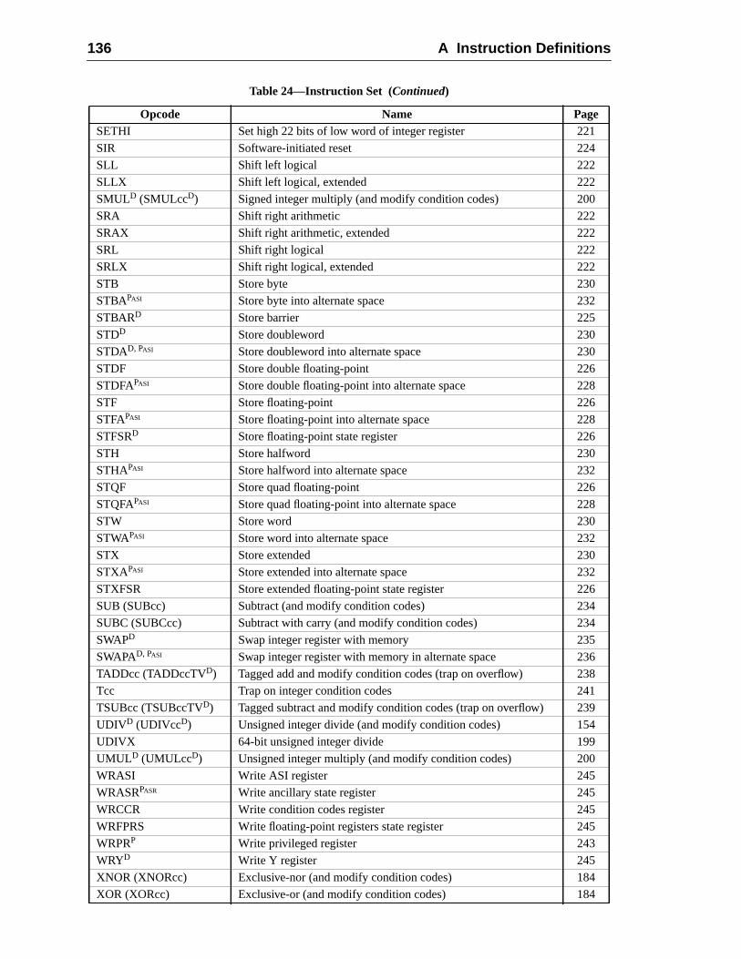
136 A Instruction Definitions
SETHI Set high 22 bits of low word of integer register 221
SIR Software-initiated reset 224
SLL Shift left logical 222
SLLX Shift left logical, extended 222
SMULD (SMULccD) Signed integer multiply (and modify condition codes) 200
SRA Shift right arithmetic 222
SRAX Shift right arithmetic, extended 222
SRL Shift right logical 222
SRLX Shift right logical, extended 222
STB Store byte 230
STBAPASI Store byte into alternate space 232
STBARD Store barrier 225
STDD Store doubleword 230
STDAD, PASI Store doubleword into alternate space 230
STDF Store double floating-point 226
STDFAPASI Store double floating-point into alternate space 228
STF Store floating-point 226
STFAPASI Store floating-point into alternate space 228
STFSRD Store floating-point state register 226
STH Store halfword 230
STHAPASI Store halfword into alternate space 232
STQF Store quad floating-point 226
STQFAPASI Store quad floating-point into alternate space 228
STW Store word 230
STWAPASI Store word into alternate space 232
STX Store extended 230
STXAPASI Store extended into alternate space 232
STXFSR Store extended floating-point state register 226
SUB (SUBcc) Subtract (and modify condition codes) 234
SUBC (SUBCcc) Subtract with carry (and modify condition codes) 234
SWAPD Swap integer register with memory 235
SWAPAD, PASI Swap integer register with memory in alternate space 236
TADDcc (TADDccTVD) Tagged add and modify condition codes (trap on overflow) 238
Tcc Trap on integer condition codes 241
TSUBcc (TSUBccTVD) Tagged subtract and modify condition codes (trap on overflow) 239
UDIVD (UDIVccD) Unsigned integer divide (and modify condition codes) 154
UDIVX 64-bit unsigned integer divide 199
UMULD (UMULccD) Unsigned integer multiply (and modify condition codes) 200
WRASI Write ASI register 245
WRASRPASR Write ancillary state register 245
WRCCR Write condition codes register 245
WRFPRS Write floating-point registers state register 245
WRPRP Write privileged register 243
WRYD Write Y register 245
XNOR (XNORcc) Exclusive-nor (and modify condition codes) 184
XOR (XORcc) Exclusive-or (and modify condition codes) 184
Table 24—Instruction Set (Continued)
Opcode Name Page
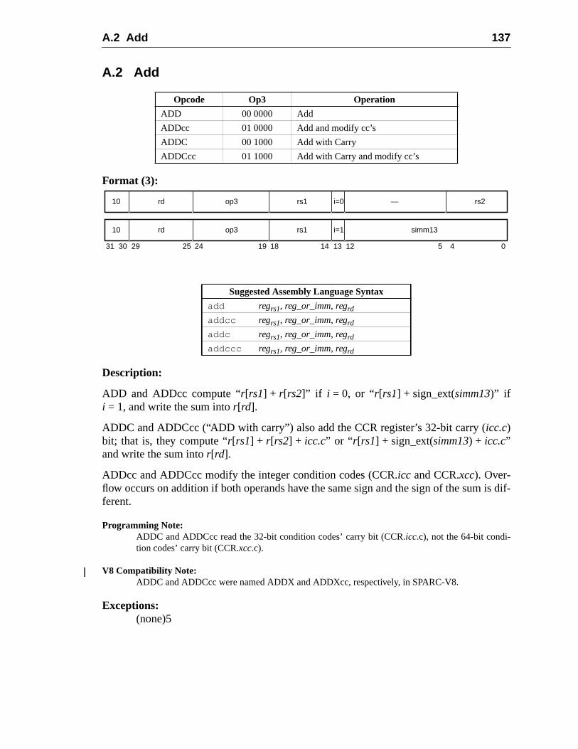
A.2 Add 137
is dif-
A.2 Add
Format (3):
Description:
ADD and ADDcc compute “r[rs1] + r[rs2]” if i = 0, or “r[rs1] + sign_ext(simm13)” ifi = 1, and write the sum intor[rd].
ADDC and ADDCcc (“ADD with carry”) also add the CCR register’s 32-bit carry (icc.c)bit; that is, they compute “r[rs1] + r[rs2] + icc.c” or “ r[rs1] + sign_ext(simm13) + icc.c”and write the sum intor[rd].
ADDcc and ADDCcc modify the integer condition codes (CCR.icc and CCR.xcc). Over-flow occurs on addition if both operands have the same sign and the sign of the sumferent.
Programming Note:ADDC and ADDCcc read the 32-bit condition codes’ carry bit (CCR.icc.c), not the 64-bit condi-tion codes’ carry bit (CCR.xcc.c).
V8 Compatibility Note:ADDC and ADDCcc were named ADDX and ADDXcc, respectively, in SPARC-V8.
Exceptions:(none)5
Opcode Op3 Operation
ADD 00 0000 Add
ADDcc 01 0000 Add and modify cc’s
ADDC 00 1000 Add with Carry
ADDCcc 01 1000 Add with Carry and modify cc’s
Suggested Assembly Language Syntax
add regrs1, reg_or_imm, regrd
addcc regrs1, reg_or_imm, regrd
addc regrs1, reg_or_imm, regrd
addccc regrs1, reg_or_imm, regrd
31 24 02530 29 19 18
rd10 op3 —
14 13 12 5 4
rs1 rs2i=0
rd10 op3 rs1 simm13i=1
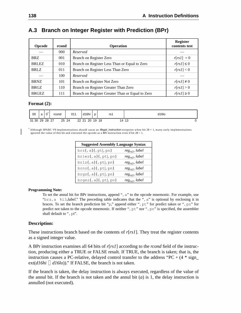
138 A Instruction Definitions
e
s
thesign_
lue of
A.3 Branch on Integer Register with Prediction (BPr)
Format (2):
* Although SPARC V9 implementations should cause an illegal_instruction exception when bit 28 = 1, many early implementationsignored the value of this bit and executed the opcode as a BPr instruction even if bit 28 = 1.
Programming Note:To set the annul bit for BPr instructions, append “,a ” to the opcode mnemonic. For example, us“brz,a %i3 ,label.” The preceding table indicates that the “,a ” is optional by enclosing it inbraces. To set the branch prediction bit “p,” append either “,pt ” for predict taken or “,pn ” forpredict not taken to the opcode mnemonic. If neither “,pt ” nor “ ,pn ” is specified, the assemblershall default to “,p t”.
Description:
These instructions branch based on the contents ofr[rs1]. They treat the register contentas a signed integer value.
A BPr instruction examines all 64 bits ofr[rs1] according to thercondfield of the instruc-tion, producing either a TRUE or FALSE result. If TRUE, the branch is taken; that is,instruction causes a PC-relative, delayed control transfer to the address “PC + (4 *ext(d16hi d16lo)).” If FALSE, the branch is not taken.
If the branch is taken, the delay instruction is always executed, regardless of the vathe annul bit. If the branch is not taken and the annul bit (a) is 1, the delay instruction isannulled (not executed).
Opcode rcond OperationRegister
contents test
— 000 Reserved —
BRZ 001 Branch on Register Zero r[rs1] = 0
BRLEZ 010 Branch on Register Less Than or Equal to Zero r[rs1] ≤ 0
BRLZ 011 Branch on Register Less Than Zero r[rs1] < 0
— 100 Reserved —
BRNZ 101 Branch on Register Not Zero r[rs1] ≠ 0
BRGZ 110 Branch on Register Greater Than Zero r[rs1] > 0
BRGEZ 111 Branch on Register Greater Than or Equal to Zero r[rs1] ≥ 0
Suggested Assembly Language Syntax
brz { ,a }{ ,pt |,pn } regrs1, label
brlez { ,a }{ ,pt |,pn } regrs1, label
brlz { ,a }{ ,pt |,pn } regrs1, label
brnz { ,a }{ ,pt |,pn } regrs1, label
brgz { ,a }{ ,pt |,pn } regrs1, label
brgez { ,a }{ ,pt |,pn } regrs1, label
31 141924 18 13 027 2530 29 28 22 21 20
00 a 0* rcond 011 d16hi p rs1 d16lo
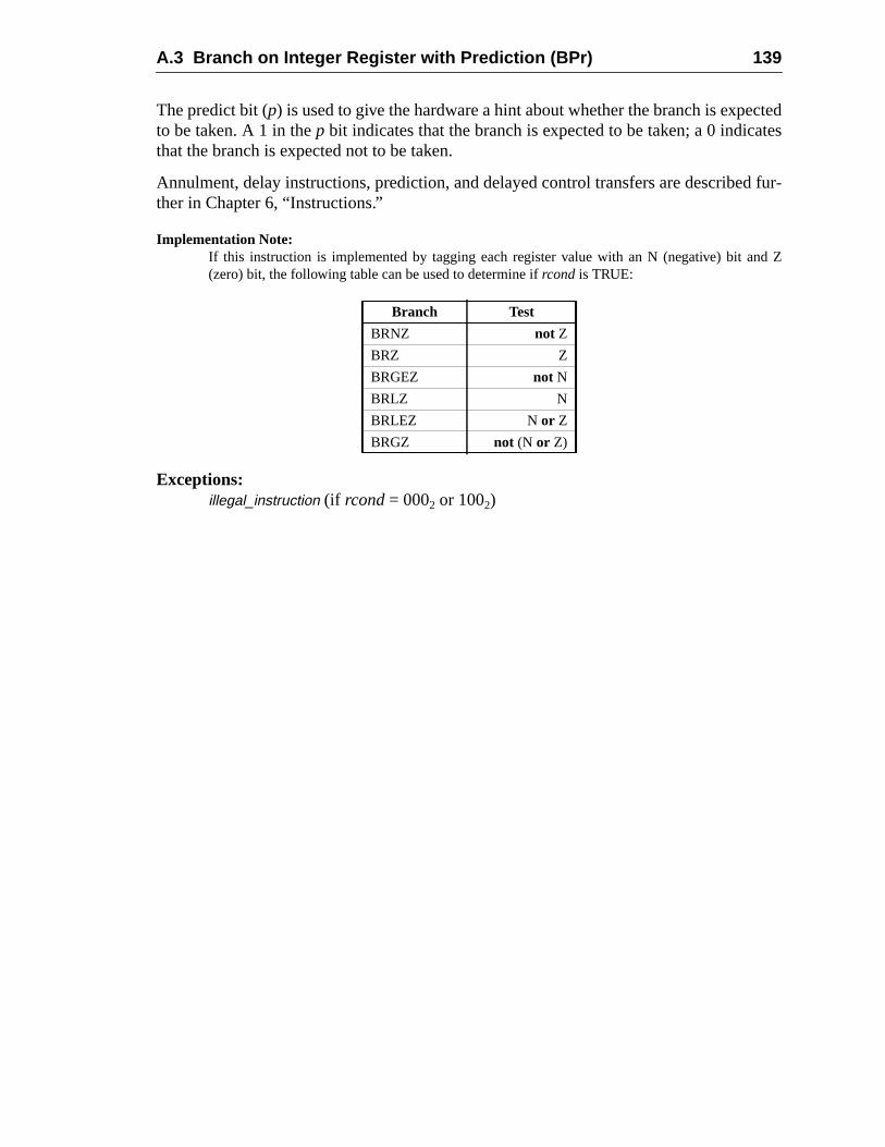
A.3 Branch on Integer Register with Prediction (BPr) 139
cted
d fur-
d Z
The predict bit (p) is used to give the hardware a hint about whether the branch is expeto be taken. A 1 in thep bit indicates that the branch is expected to be taken; a 0 indicatesthat the branch is expected not to be taken.
Annulment, delay instructions, prediction, and delayed control transfers are describether in Chapter 6, “Instructions.”
Implementation Note:If this instruction is implemented by tagging each register value with an N (negative) bit an(zero) bit, the following table can be used to determine ifrcond is TRUE:
Exceptions:illegal_instruction (if rcond= 0002 or 1002)
Branch Test
BRNZ not Z
BRZ Z
BRGEZ not N
BRLZ N
BRLEZ N or Z
BRGZ not (N or Z)
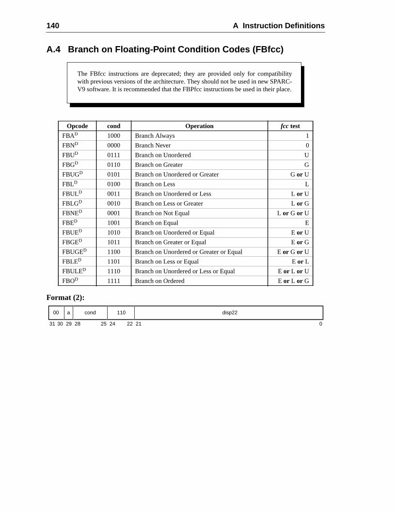
140 A Instruction Definitions
A.4 Branch on Floating-Point Condition Codes (FBfcc)
Format (2):
Opcode cond Operation fcc test
FBAD 1000 Branch Always 1
FBND 0000 Branch Never 0
FBUD 0111 Branch on Unordered U
FBGD 0110 Branch on Greater G
FBUGD 0101 Branch on Unordered or Greater Gor U
FBLD 0100 Branch on Less L
FBULD 0011 Branch on Unordered or Less Lor U
FBLGD 0010 Branch on Less or Greater Lor G
FBNED 0001 Branch on Not Equal Lor G or U
FBED 1001 Branch on Equal E
FBUED 1010 Branch on Unordered or Equal Eor U
FBGED 1011 Branch on Greater or Equal Eor G
FBUGED 1100 Branch on Unordered or Greater or Equal Eor G or U
FBLED 1101 Branch on Less or Equal Eor L
FBULED 1110 Branch on Unordered or Less or Equal Eor L or U
FBOD 1111 Branch on Ordered Eor L or G
The FBfcc instructions are deprecated; they are provided only for compatibilitywith previous versions of the architecture. They should not be used in new SPARC-V9 software. It is recommended that the FBPfcc instructions be used in their place.
31 24 02530 29 28 22 21
cond00 a 110 disp22
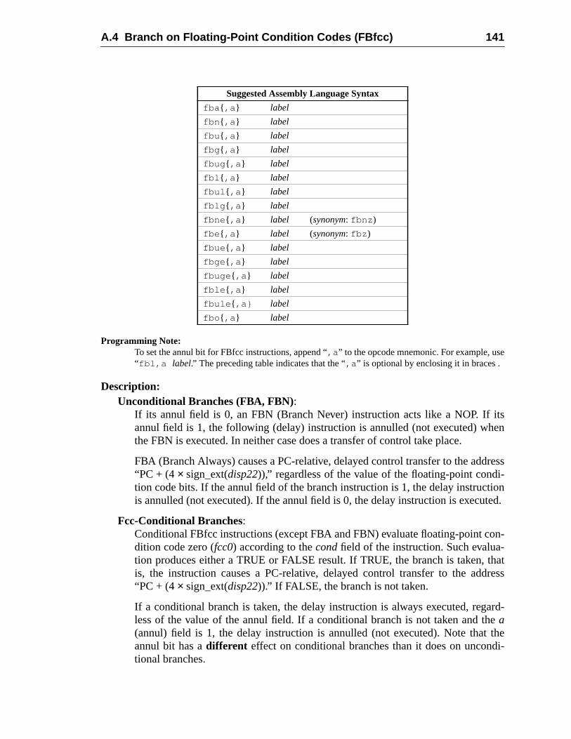
A.4 Branch on Floating-Point Condition Codes (FBfcc) 141
e
itsen
ressi-tionted.
on--thatdress
ard-ethe
di-
Programming Note:To set the annul bit for FBfcc instructions, append “,a ” to the opcode mnemonic. For example, us“ fbl,a label.” The preceding table indicates that the “,a ” is optional by enclosing it in braces .
Description:Unconditional Branches (FBA, FBN):
If its annul field is 0, an FBN (Branch Never) instruction acts like a NOP. Ifannul field is 1, the following (delay) instruction is annulled (not executed) whthe FBN is executed. In neither case does a transfer of control take place.
FBA (Branch Always) causes a PC-relative, delayed control transfer to the add“PC + (4× sign_ext(disp22)),” regardless of the value of the floating-point condtion code bits. If the annul field of the branch instruction is 1, the delay instrucis annulled (not executed). If the annul field is 0, the delay instruction is execu
Fcc-Conditional Branches:Conditional FBfcc instructions (except FBA and FBN) evaluate floating-point cdition code zero (fcc0) according to thecondfield of the instruction. Such evaluation produces either a TRUE or FALSE result. If TRUE, the branch is taken,is, the instruction causes a PC-relative, delayed control transfer to the ad“PC + (4× sign_ext(disp22)).” If FALSE, the branch is not taken.
If a conditional branch is taken, the delay instruction is always executed, regless of the value of the annul field. If a conditional branch is not taken and tha(annul) field is 1, the delay instruction is annulled (not executed). Note thatannul bit has adifferent effect on conditional branches than it does on uncontional branches.
Suggested Assembly Language Syntax
fba { ,a } label
fbn { ,a } label
fbu { ,a } label
fbg { ,a } label
fbug { ,a } label
fbl { ,a } label
fbul { ,a } label
fblg { ,a } label
fbne { ,a } label (synonym: fbnz )
fbe { ,a } label (synonym: fbz )
fbue { ,a } label
fbge { ,a } label
fbuge { ,a } label
fble { ,a } label
fbule { ,a} label
fbo { ,a } label
142 A Instruction Definitions
rther
pare
n is
Annulment, delay instructions, and delayed control transfers are described fuin Chapter 6, “Instructions.”
V8 Compatibility Note:Unlike SPARC-V8, SPARC-V9 does not require an instruction between a floating-point comoperation and a floating-point branch (FBfcc, FBPfcc).
If FPRS.FEF = 0 or PSTATE.PEF = 0, or if an FPU is not present, the FBfcc instructionot executed and instead, generates anfp_disabled exception.
Exceptions:fp_disabled
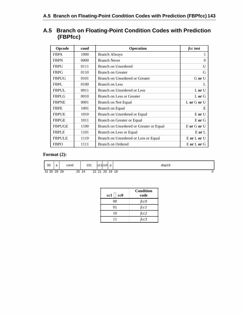
A.5 Branch on Floating-Point Condition Codes with Prediction (FBPfcc) 143
A.5 Branch on Floating-Point Condition Codes with Prediction(FBPfcc)
Format (2):
Opcode cond Operation fcc test
FBPA 1000 Branch Always 1
FBPN 0000 Branch Never 0
FBPU 0111 Branch on Unordered U
FBPG 0110 Branch on Greater G
FBPUG 0101 Branch on Unordered or Greater Gor U
FBPL 0100 Branch on Less L
FBPUL 0011 Branch on Unordered or Less Lor U
FBPLG 0010 Branch on Less or Greater Lor G
FBPNE 0001 Branch on Not Equal Lor G or U
FBPE 1001 Branch on Equal E
FBPUE 1010 Branch on Unordered or Equal Eor U
FBPGE 1011 Branch on Greater or Equal Eor G
FBPUGE 1100 Branch on Unordered or Greater or Equal Eor G or U
FBPLE 1101 Branch on Less or Equal Eor L
FBPULE 1110 Branch on Unordered or Less or Equal Eor L or U
FBPO 1111 Branch on Ordered Eor L or G
cc1 cc0Condition
code
00 fcc0
01 fcc1
10 fcc2
11 fcc3
31 1924 18 02530 29 28 22 21 20
00 a cond 101 cc1 p disp19cc0
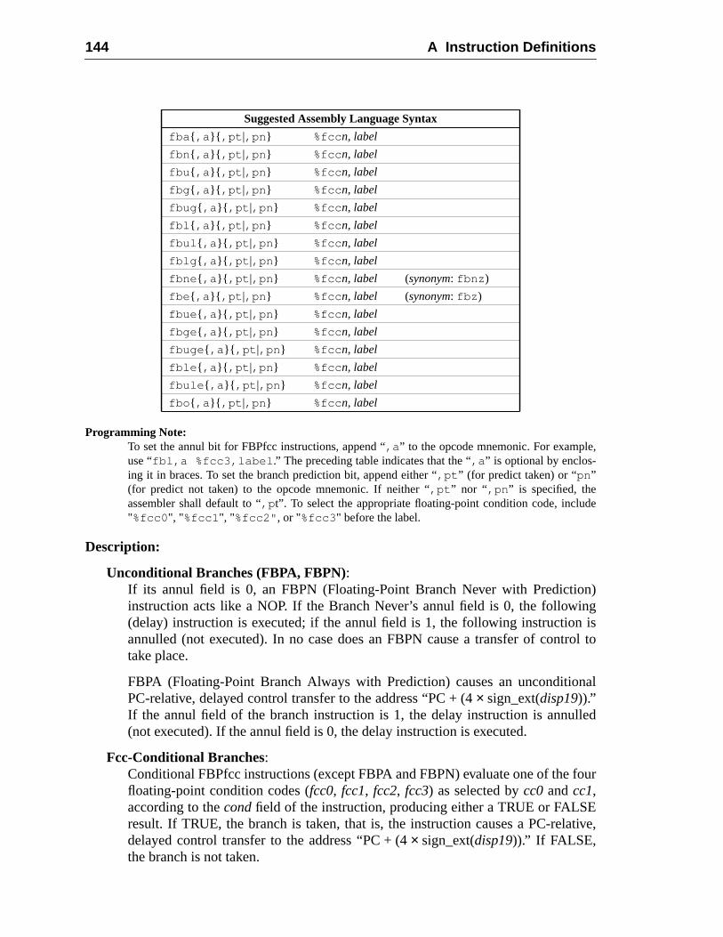
144 A Instruction Definitions
,
de
n)ngis
rol to
nal
lled
four
Etive,
Programming Note:To set the annul bit for FBPfcc instructions, append “,a ” to the opcode mnemonic. For exampleuse “fbl,a %fcc3,label .” The preceding table indicates that the “,a ” is optional by enclos-ing it in braces. To set the branch prediction bit, append either “,pt ” (for predict taken) or “pn”(for predict not taken) to the opcode mnemonic. If neither “,pt ” nor “ ,pn ” is specified, theassembler shall default to “,p t”. To select the appropriate floating-point condition code, inclu"%fcc0 ", "%fcc1 ", "%fcc2" , or "%fcc3 " before the label.
Description:
Unconditional Branches (FBPA, FBPN):If its annul field is 0, an FBPN (Floating-Point Branch Never with Predictioinstruction acts like a NOP. If the Branch Never’s annul field is 0, the followi(delay) instruction is executed; if the annul field is 1, the following instructionannulled (not executed). In no case does an FBPN cause a transfer of conttake place.
FBPA (Floating-Point Branch Always with Prediction) causes an unconditioPC-relative, delayed control transfer to the address “PC + (4× sign_ext(disp19)).”If the annul field of the branch instruction is 1, the delay instruction is annu(not executed). If the annul field is 0, the delay instruction is executed.
Fcc-Conditional Branches:Conditional FBPfcc instructions (except FBPA and FBPN) evaluate one of thefloating-point condition codes (fcc0, fcc1, fcc2, fcc3) as selected bycc0 andcc1,according to thecondfield of the instruction, producing either a TRUE or FALSresult. If TRUE, the branch is taken, that is, the instruction causes a PC-reladelayed control transfer to the address “PC + (4× sign_ext(disp19)).” If FALSE,the branch is not taken.
Suggested Assembly Language Syntax
fba { ,a }{ ,pt |,pn } %fcc n, label
fbn { ,a }{ ,pt |,pn } %fcc n, label
fbu { ,a }{ ,pt |,pn } %fcc n, label
fbg { ,a }{ ,pt |,pn } %fcc n, label
fbug { ,a }{ ,pt |,pn } %fcc n, label
fbl { ,a }{ ,pt |,pn } %fcc n, label
fbul { ,a }{ ,pt |,pn } %fcc n, label
fblg { ,a }{ ,pt |,pn } %fcc n, label
fbne { ,a }{ ,pt |,pn } %fcc n, label (synonym: fbnz )
fbe { ,a }{ ,pt |,pn } %fcc n, label (synonym: fbz )
fbue { ,a }{ ,pt |,pn } %fcc n, label
fbge { ,a }{ ,pt |,pn } %fcc n, label
fbuge { ,a }{ ,pt |,pn } %fcc n, label
fble { ,a }{ ,pt |,pn } %fcc n, label
fbule { ,a }{ ,pt |,pn } %fcc n, label
fbo { ,a }{ ,pt |,pn } %fcc n, label
A.5 Branch on Floating-Point Condition Codes with Prediction (FBPfcc) 145
ard-ethe
di-
h ise
rther
n is
pare
If a conditional branch is taken, the delay instruction is always executed, regless of the value of the annul field. If a conditional branch is not taken and tha(annul) field is 1, the delay instruction is annulled (not executed). Note thatannul bit has adifferent effect on conditional branches than it does on uncontional branches.
The predict bit (p) is used to give the hardware a hint about whether the brancexpected to be taken. A 1 in thep bit indicates that the branch is expected to btaken. A 0 indicates that the branch is expected not to be taken.
Annulment, delay instructions, and delayed control transfers are described fuin Chapter 6, “Instructions.”
If FPRS.FEF = 0 or PSTATE.PEF = 0, or if an FPU is not present, an FBPfcc instructionot executed and instead, generates anfp_disabled exception.
V8 Compatibility Note:Unlike SPARC-V8, SPARC-V9 does not require an instruction between a floating-point comoperation and a floating-point branch (FBfcc, FBPfcc).
Exceptions:fp_disabled
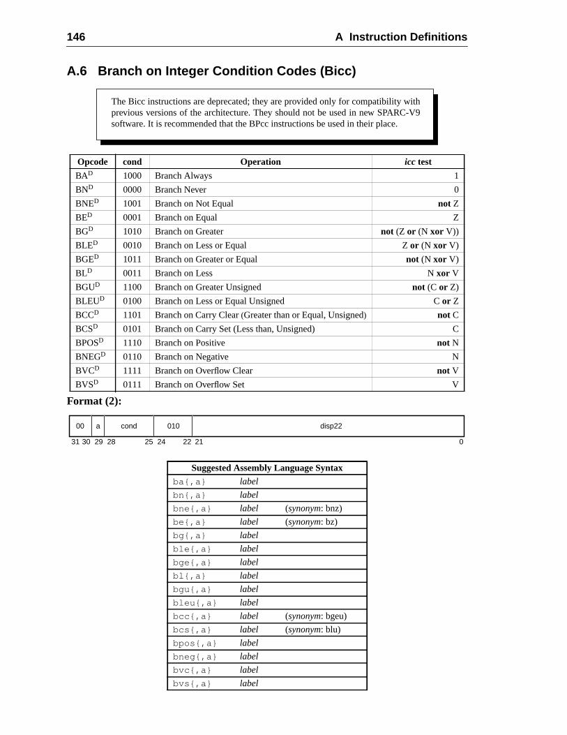
146 A Instruction Definitions
A.6 Branch on Integer Condition Codes (Bicc)
Format (2):
Opcode cond Operation icc test
BAD 1000 Branch Always 1
BND 0000 Branch Never 0
BNED 1001 Branch on Not Equal not Z
BED 0001 Branch on Equal Z
BGD 1010 Branch on Greater not (Z or (N xor V))
BLED 0010 Branch on Less or Equal Zor (N xor V)
BGED 1011 Branch on Greater or Equal not (N xor V)
BLD 0011 Branch on Less Nxor V
BGUD 1100 Branch on Greater Unsigned not (C or Z)
BLEUD 0100 Branch on Less or Equal Unsigned Cor Z
BCCD 1101 Branch on Carry Clear(Greater than or Equal, Unsigned) not C
BCSD 0101 Branch on Carry Set (Less than, Unsigned) C
BPOSD 1110 Branch on Positive not N
BNEGD 0110 Branch on Negative N
BVCD 1111 Branch on Overflow Clear not V
BVSD 0111 Branch on Overflow Set V
Suggested Assembly Language Syntax
ba{,a} label
bn{,a} label
bne{,a} label (synonym: bnz)
be{,a} label (synonym: bz)
bg{,a} label
ble{,a} label
bge{,a} label
bl{,a} label
bgu{,a} label
bleu{,a} label
bcc{,a} label (synonym: bgeu)
bcs{,a} label (synonym: blu)
bpos{,a} label
bneg{,a} label
bvc{,a} label
bvs{,a} label
The Bicc instructions are deprecated; they are provided only for compatibility withprevious versions of the architecture. They should not be used in new SPARC-V9software. It is recommended that the BPcc instructions be used in their place.
31 24 02530 29 28 22 21
00 a cond 010 disp22
A.6 Branch on Integer Condition Codes (Bicc) 147
e
uler
sfer
ld is
ger
uc-
dless
l bitnal
rther
Programming Note:To set the annul bit for Bicc instructions, append “,a ” to the opcode mnemonic. For example, us“bgu,a label.” The preceding table indicates that the “,a ” is optional by enclosing it in braces.
Description:Unconditional Branches (BA, BN):
If its annul field is 0, a BN (Branch Never) instruction acts like a NOP. If its annfield is 1, the following (delay) instruction is annulled (not executed). In neithcase does a transfer of control take place.
BA (Branch Always) causes an unconditional PC-relative, delayed control tranto the address “PC + (4× sign_ext(disp22)).” If the annul field of the branchinstruction is 1, the delay instruction is annulled (not executed). If the annul fie0, the delay instruction is executed.
Icc-Conditional Branches:Conditional Bicc instructions (all except BA and BN) evaluate the 32-bit intecondition codes (icc), according to thecond field of the instruction, producingeither a TRUE or FALSE result. If TRUE, the branch is taken, that is, the instrtion causes a PC-relative, delayed control transfer to the address “PC + (4× sign_ext(disp22)).” If FALSE, the branch is not taken.
If a conditional branch is taken, the delay instruction is always executed regarof the value of the annul field. If a conditional branch is not taken and thea (annul)field is 1, the delay instruction is annulled (not executed). Note that the annuhas adifferent effect on conditional branches than it does on unconditiobranches.
Annulment, delay instructions, and delayed control transfers are described fuin Chapter 6, “Instructions.”
Exceptions:(none)
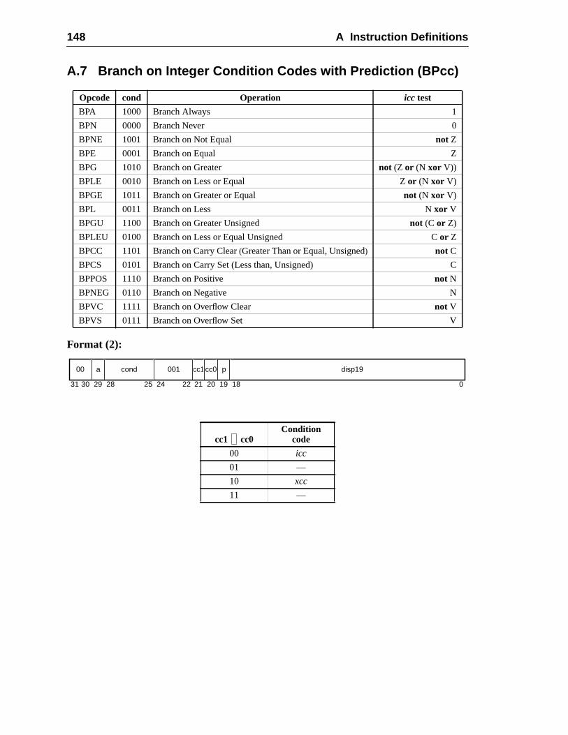
148 A Instruction Definitions
A.7 Branch on Integer Condition Codes with Prediction (BPcc)
Format (2):
Opcode cond Operation icc test
BPA 1000 Branch Always 1
BPN 0000 Branch Never 0
BPNE 1001 Branch on Not Equal not Z
BPE 0001 Branch on Equal Z
BPG 1010 Branch on Greater not (Z or (N xor V))
BPLE 0010 Branch on Less or Equal Zor (N xor V)
BPGE 1011 Branch on Greater or Equal not (N xor V)
BPL 0011 Branch on Less Nxor V
BPGU 1100 Branch on Greater Unsigned not (C or Z)
BPLEU 0100 Branch on Less or Equal Unsigned Cor Z
BPCC 1101 Branch on Carry Clear(Greater Than or Equal, Unsigned) not C
BPCS 0101 Branch on Carry Set (Less than, Unsigned) C
BPPOS 1110 Branch on Positive not N
BPNEG 0110 Branch on Negative N
BPVC 1111 Branch on Overflow Clear not V
BPVS 0111 Branch on Overflow Set V
cc1 cc0Condition
code
00 icc
01 —
10 xcc
11 —
31 1924 18 02530 29 28 22 21 20
00 a cond 001 cc1 p disp19cc0
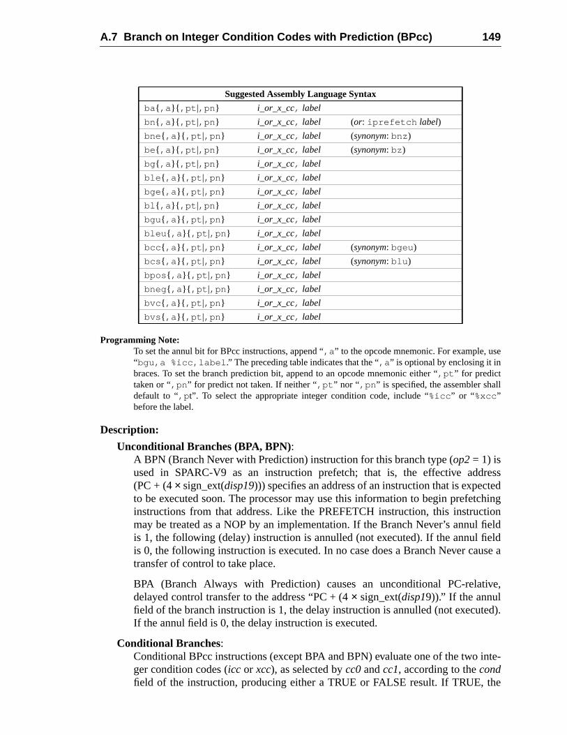
A.7 Branch on Integer Condition Codes with Prediction (BPcc) 149
e
l
resstedchingtionfieldelduse a
ive,
ed).
nte-
he
Programming Note:To set the annul bit for BPcc instructions, append “,a ” to the opcode mnemonic. For example, us“bgu,a %icc,label .” The preceding table indicates that the “,a ” is optional by enclosing it inbraces. To set the branch prediction bit, append to an opcode mnemonic either “,pt ” for predicttaken or “,pn ” for predict not taken. If neither “,pt ” nor “ ,pn ” is specified, the assembler shaldefault to “,p t”. To select the appropriate integer condition code, include “%icc ” or “ %xcc”before the label.
Description:
Unconditional Branches (BPA, BPN):A BPN (Branch Never with Prediction) instruction for this branch type (op2= 1) isused in SPARC-V9 as an instruction prefetch; that is, the effective add(PC + (4× sign_ext(disp19))) specifies an address of an instruction that is expecto be executed soon. The processor may use this information to begin prefetinstructions from that address. Like the PREFETCH instruction, this instrucmay be treated as a NOP by an implementation. If the Branch Never’s annulis 1, the following (delay) instruction is annulled (not executed). If the annul fiis 0, the following instruction is executed. In no case does a Branch Never catransfer of control to take place.
BPA (Branch Always with Prediction) causes an unconditional PC-relatdelayed control transfer to the address “PC + (4× sign_ext(disp19)).” If the annulfield of the branch instruction is 1, the delay instruction is annulled (not executIf the annul field is 0, the delay instruction is executed.
Conditional Branches:Conditional BPcc instructions (except BPA and BPN) evaluate one of the two iger condition codes (icc or xcc), as selected bycc0andcc1, according to thecondfield of the instruction, producing either a TRUE or FALSE result. If TRUE, t
Suggested Assembly Language Syntax
ba{ ,a }{ ,pt |,pn } i_or_x_cc, label
bn{ ,a }{ ,pt |,pn } i_or_x_cc, label (or: iprefetch label)
bne { ,a }{ ,pt |,pn } i_or_x_cc, label (synonym: bnz )
be{ ,a }{ ,pt |,pn } i_or_x_cc, label (synonym: bz )
bg{ ,a }{ ,pt |,pn } i_or_x_cc, label
ble { ,a }{ ,pt |,pn } i_or_x_cc, label
bge { ,a }{ ,pt |,pn } i_or_x_cc, label
bl { ,a }{ ,pt |,pn } i_or_x_cc, label
bgu { ,a }{ ,pt |,pn } i_or_x_cc, label
bleu { ,a }{ ,pt |,pn } i_or_x_cc, label
bcc { ,a }{ ,pt |,pn } i_or_x_cc, label (synonym: bgeu )
bcs { ,a }{ ,pt |,pn } i_or_x_cc, label (synonym: blu )
bpos { ,a }{ ,pt |,pn } i_or_x_cc, label
bneg { ,a }{ ,pt |,pn } i_or_x_cc, label
bvc { ,a }{ ,pt |,pn } i_or_x_cc, label
bvs { ,a }{ ,pt |,pn } i_or_x_cc, label
150 A Instruction Definitions
rans-
dless
l bital
h ise
are
branch is taken; that is, the instruction causes a PC-relative, delayed control tfer to the address “PC + (4× sign_ext(disp19)).” If FALSE, the branch is nottaken.
If a conditional branch is taken, the delay instruction is always executed regarof the value of the annul field. If a conditional branch is not taken and thea (annul)field is 1, the delay instruction is annulled (not executed). Note that the annuhas adifferent effect for conditional branches than it does for unconditionbranches.
The predict bit (p) is used to give the hardware a hint about whether the brancexpected to be taken. A 1 in thep bit indicates that the branch is expected to btaken; a 0 indicates that the branch is expected not to be taken.
Annulment, delay instructions, prediction, and delayed control transfersdescribed further in Chapter 6, “Instructions.”
Exceptions:illegal_instruction (cc1 cc0= 012 or 112)
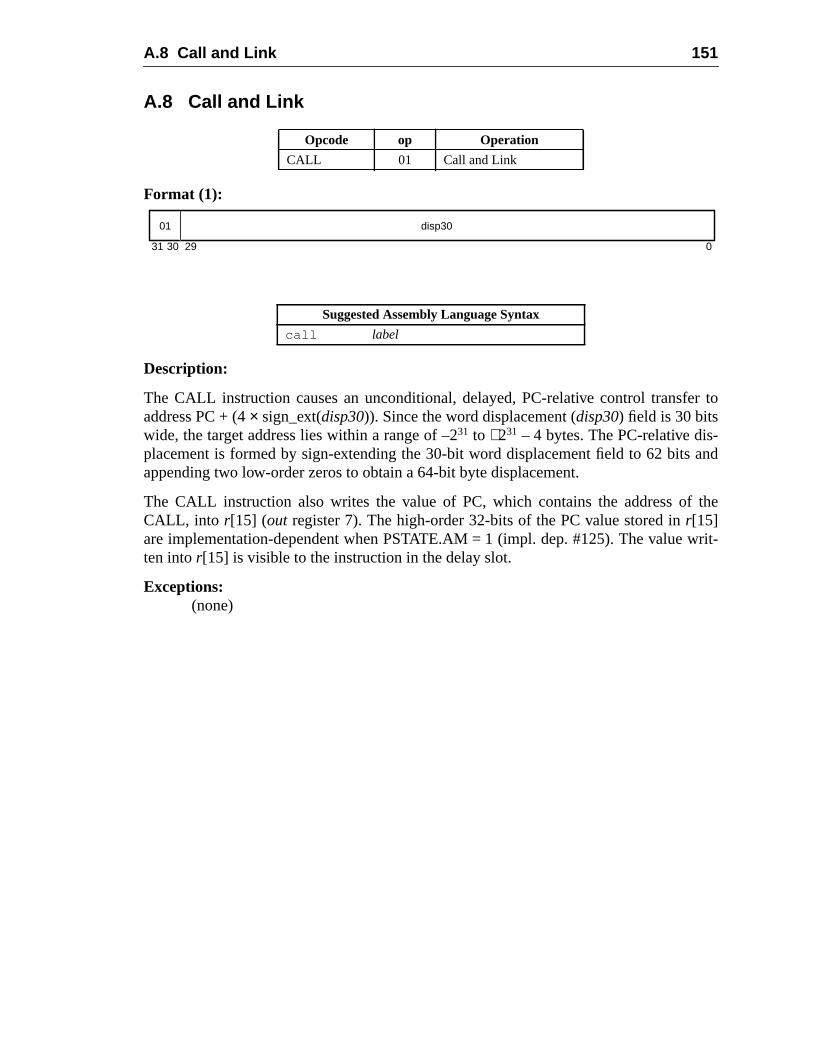
A.8 Call and Link 151
er to
-and
the
writ-
A.8 Call and Link
Format (1):
Description:
The CALL instruction causes an unconditional, delayed, PC-relative control transfaddress PC + (4× sign_ext(disp30)). Since the word displacement (disp30) field is 30 bitswide, the target address lies within a range of –231 to +231 – 4 bytes. The PC-relative displacement is formed by sign-extending the 30-bit word displacement field to 62 bitsappending two low-order zeros to obtain a 64-bit byte displacement.
The CALL instruction also writes the value of PC, which contains the address ofCALL, into r[15] (out register 7). The high-order 32-bits of the PC value stored inr[15]are implementation-dependent when PSTATE.AM = 1 (impl. dep. #125). The valueten intor[15] is visible to the instruction in the delay slot.
Exceptions:(none)
Opcode op Operation
CALL 01 Call and Link
Suggested Assembly Language Syntax
call label
31 030 29
01 disp30
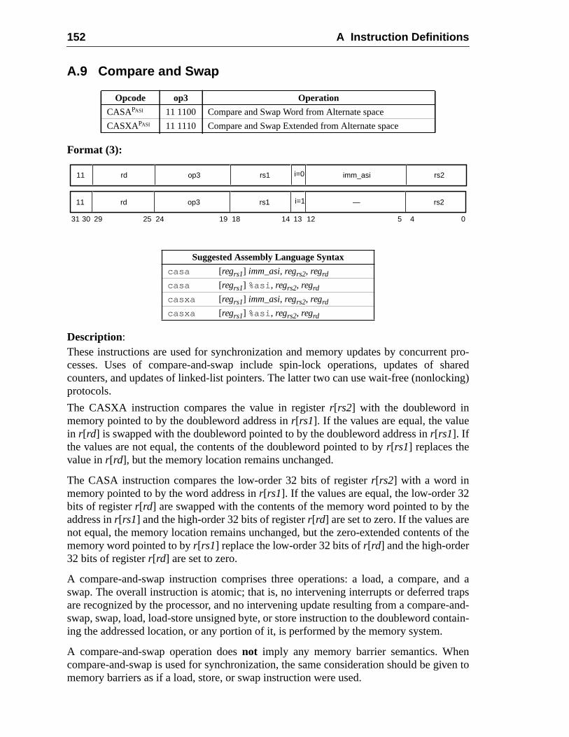
152 A Instruction Definitions
t pro-sharedking)
2theeof the
and arapse-and-ntain-
niven to
A.9 Compare and Swap
Format (3):
Description:These instructions are used for synchronization and memory updates by concurrencesses. Uses of compare-and-swap include spin-lock operations, updates ofcounters, and updates of linked-list pointers. The latter two can use wait-free (nonlocprotocols.
The CASXA instruction compares the value in registerr[rs2] with the doubleword inmemory pointed to by the doubleword address inr[rs1]. If the values are equal, the valuein r[rd] is swapped with the doubleword pointed to by the doubleword address inr[rs1]. Ifthe values are not equal, the contents of the doubleword pointed to byr[rs1] replaces thevalue inr[rd], but the memory location remains unchanged.
The CASA instruction compares the low-order 32 bits of registerr[rs2] with a word inmemory pointed to by the word address inr[rs1]. If the values are equal, the low-order 3bits of registerr[rd] are swapped with the contents of the memory word pointed to byaddress inr[rs1] and the high-order 32 bits of registerr[rd] are set to zero. If the values arnot equal, the memory location remains unchanged, but the zero-extended contentsmemory word pointed to byr[rs1] replace the low-order 32 bits ofr[rd] and the high-order32 bits of registerr[rd] are set to zero.
A compare-and-swap instruction comprises three operations: a load, a compare,swap. The overall instruction is atomic; that is, no intervening interrupts or deferred tare recognized by the processor, and no intervening update resulting from a comparswap, swap, load, load-store unsigned byte, or store instruction to the doubleword coing the addressed location, or any portion of it, is performed by the memory system.
A compare-and-swap operation doesnot imply any memory barrier semantics. Whecompare-and-swap is used for synchronization, the same consideration should be gmemory barriers as if a load, store, or swap instruction were used.
Opcode op3 Operation
CASAPASI 11 1100 Compare and Swap Word from Alternate space
CASXAPASI 11 1110 Compare and Swap Extended from Alternate space
Suggested Assembly Language Syntax
casa [regrs1] imm_asi, regrs2, regrd
casa [regrs1] %asi , regrs2, regrd
casxa [regrs1] imm_asi, regrs2, regrd
casxa [regrs1] %asi , regrs2, regrd
31 141924 18 13 12 5 4 02530 29
11 rd op3 rs1 i=0 imm_asi rs2
11 rd op3 rs1 i=1 — rs2
A.9 Compare and Swap 153
valueble,
DMA
, even
s aree andory
A compare-and-swap operation behaves as if it performs a store, either of a newfrom r[rd] or of the previous value in memory. The addressed location must be writaeven if the values in memory andr[rs2] are not equal.
If i = 0, the address space of the memory location is specified in theimm_asifield; if i = 1,the address space is specified in the ASI register.
A mem_address_not_aligned exception is generated if the address inr[rs1] is not properlyaligned. CASXA and CASA cause aprivileged_action exception if PSTATE.PRIV = 0 andbit 7 of the ASI is zero.
The coherence and atomicity of memory operations between processors and I/Omemory accesses are implementation-dependent (impl. dep #120).
Implementation Note:An implementation might cause an exception due to an error during the store memory accessthough there was no error during the load memory access.
Programming Note:Compare and Swap (CAS) and Compare and Swap Extended (CASX) synthetic instructionavailable for “big endian” memory accesses. Compare and Swap Little (CASL) and ComparSwap Extended Little (CASXL) synthetic instructions are available for “little endian” memaccesses. See G.3, “Synthetic Instructions,” for these synthetic instructions’ syntax.
The compare-and-swap instructions do not affect the condition codes.
Exceptions:privileged_actionmem_address_not_aligneddata_access_exceptiondata_access_MMU_missdata_access_protectiondata_access_errorasync_data_error
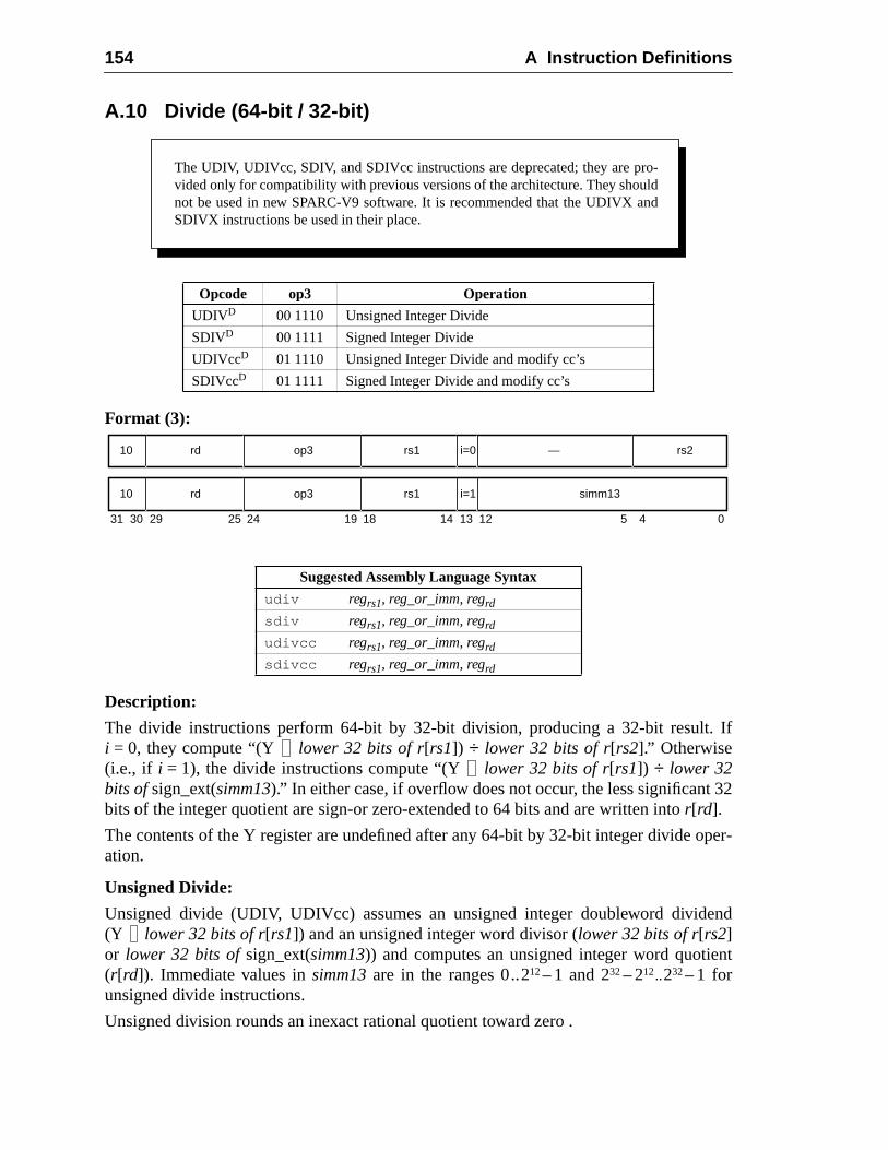
154 A Instruction Definitions
. If
32
per-
end
nt
A.10 Divide (64-bit / 32-bit)
Format (3):
Description:
The divide instructions perform 64-bit by 32-bit division, producing a 32-bit resulti = 0, they compute “(Y lower 32 bits of r[rs1]) ÷ lower 32 bits of r[rs2].” Otherwise(i.e., if i = 1), the divide instructions compute “(Y lower 32 bits of r[rs1]) ÷ lower 32bits ofsign_ext(simm13).” In either case, if overflow does not occur, the less significantbits of the integer quotient are sign-or zero-extended to 64 bits and are written intor[rd].
The contents of the Y register are undefined after any 64-bit by 32-bit integer divide oation.
Unsigned Divide:
Unsigned divide (UDIV, UDIVcc) assumes an unsigned integer doubleword divid(Y lower 32 bits of r[rs1]) and an unsigned integer word divisor (lower 32 bits of r[rs2]or lower 32 bits ofsign_ext(simm13)) and computes an unsigned integer word quotie(r[rd]). Immediate values insimm13are in the ranges 0..212– 1 and 232– 212..232– 1 forunsigned divide instructions.
Unsigned division rounds an inexact rational quotient toward zero .
Opcode op3 Operation
UDIVD 00 1110 Unsigned Integer Divide
SDIVD 00 1111 Signed Integer Divide
UDIVccD 01 1110 Unsigned Integer Divide and modify cc’s
SDIVccD 01 1111 Signed Integer Divide and modify cc’s
Suggested Assembly Language Syntax
udiv regrs1, reg_or_imm, regrdsdiv regrs1, reg_or_imm, regrdudivcc regrs1, reg_or_imm, regrdsdivcc regrs1, reg_or_imm, regrd
The UDIV, UDIVcc, SDIV, and SDIVcc instructions are deprecated; they are pro-vided only for compatibility with previous versions of the architecture. They shouldnot be used in new SPARC-V9 software. It is recommended that the UDIVX andSDIVX instructions be used in their place.
31 24 02530 29 19 18
rd10 op3 —
14 13 12 5 4
rs1 rs2i=0
rd10 op3 rs1 simm13i=1
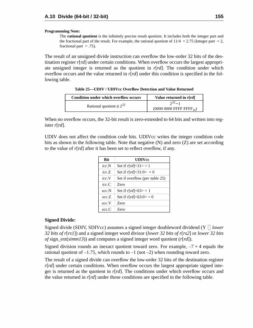
A.10 Divide (64-bit / 32-bit) 155
nd= 2,
des-pri-
-
reg-
oderding
isterinte-d
Programming Note:The rational quotient is the infinitely precise result quotient. It includes both the integer part athe fractional part of the result. For example, the rational quotient of 11/4 = 2.75 (Integer partfractional part = .75).
The result of an unsigned divide instruction can overflow the low-order 32 bits of thetination registerr[rd] under certain conditions. When overflow occurs the largest approate unsigned integer is returned as the quotient inr[rd]. The condition under whichoverflow occurs and the value returned inr[rd] under this condition is specified in the following table.
When no overflow occurs, the 32-bit result is zero-extended to 64 bits and written intoisterr[rd].
UDIV does not affect the condition code bits. UDIVcc writes the integer condition cbits as shown in the following table. Note that negative (N) and zero (Z) are set accoto the value ofr[rd] after it has been set to reflect overflow, if any.
Signed Divide:
Signed divide (SDIV, SDIVcc) assumes a signed integer doubleword dividend (Ylower32 bits of r[rs1]) and a signed integer word divisor (lower 32 bits of r[rs2] or lower 32 bitsof sign_ext(simm13)) and computes a signed integer word quotient (r[rd]).
Signed division rounds an inexact quotient toward zero. For example, –7÷ 4 equals therational quotient of –1.75, which rounds to –1 (not –2) when rounding toward zero.
The result of a signed divide can overflow the low-order 32 bits of the destination regr[rd] under certain conditions. When overflow occurs the largest appropriate signedger is returned as the quotient inr[rd]. The conditions under which overflow occurs anthe value returned inr[rd] under those conditions are specified in the following table.
Table 25—UDIV / UDIVcc Overflow Detection and Value Returned
Condition under which overflow occurs Value returned inr[rd]
Rational quotient≥ 232 232−1(0000 0000 FFFF FFFF16)
Bit UDIVcc
icc.N Set ifr[rd]<31> = 1
icc.Z Set ifr[rd]<31:0> = 0
icc.V Set if overflow (per table 25)
icc.C Zero
xcc.N Set ifr[rd]<63> = 1
xcc.Z Set ifr[rd]<63:0> = 0
xcc.V Zero
xcc.C Zero
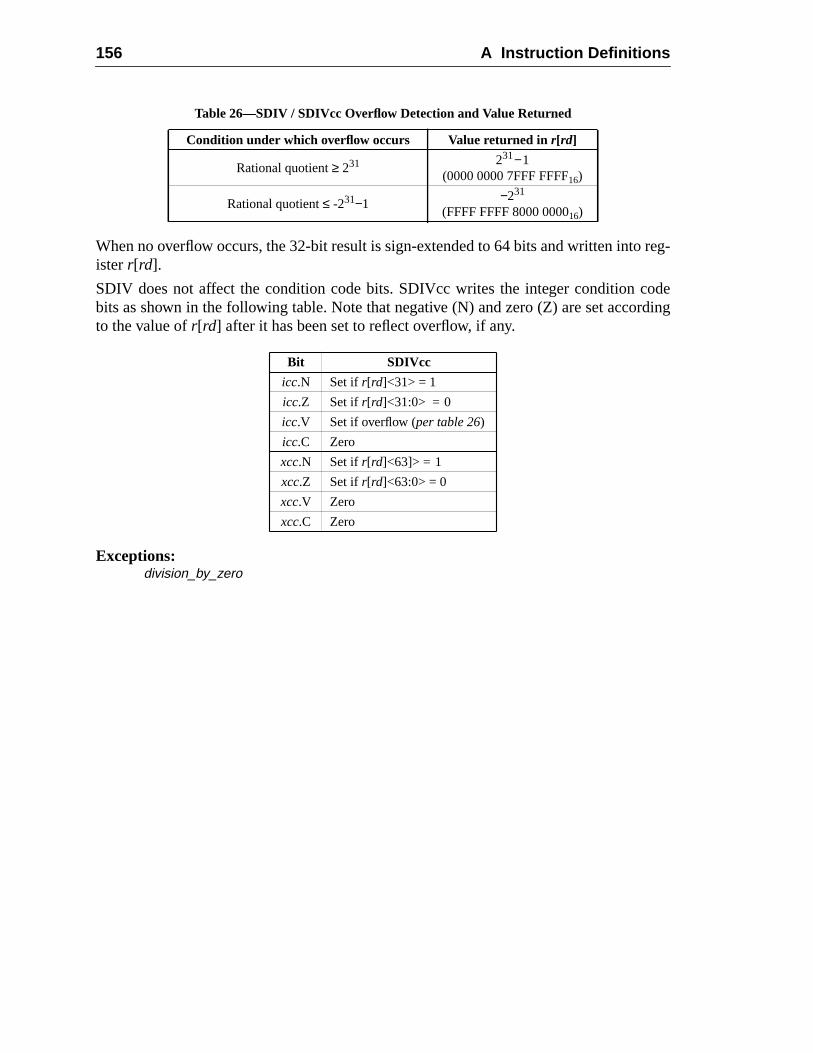
156 A Instruction Definitions
reg-
oderding
When no overflow occurs, the 32-bit result is sign-extended to 64 bits and written intoisterr[rd].
SDIV does not affect the condition code bits. SDIVcc writes the integer condition cbits as shown in the following table. Note that negative (N) and zero (Z) are set accoto the value ofr[rd] after it has been set to reflect overflow, if any.
Exceptions:division_by_zero
Table 26—SDIV / SDIVcc Overflow Detection and Value Returned
Condition under which overflow occurs Value returned inr[rd]
Rational quotient≥ 231 231−1(0000 0000 7FFF FFFF16)
Rational quotient≤ -231−1−231
(FFFF FFFF 8000 000016)
Bit SDIVcc
icc.N Set ifr[rd]<31> = 1
icc.Z Set ifr[rd]<31:0> = 0
icc.V Set if overflow (per table 26)
icc.C Zero
xcc.N Set ifr[rd]<63]> = 1
xcc.Z Set ifr[rd]<63:0> = 0
xcc.V Zero
xcc.C Zero
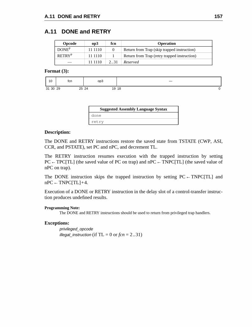
A.11 DONE and RETRY 157
ASI,
tting
uc-
A.11 DONE and RETRY
Format (3):
Description:
The DONE and RETRY instructions restore the saved state from TSTATE (CWP,CCR, and PSTATE), set PC and nPC, and decrement TL.
The RETRY instruction resumes execution with the trapped instruction by sePC←TPC[TL] (the saved value of PC on trap) and nPC←TNPC[TL] (the saved value ofnPC on trap).
The DONE instruction skips the trapped instruction by setting PC←TNPC[TL] andnPC←TNPC[TL]+4.
Execution of a DONE or RETRY instruction in the delay slot of a control-transfer instrtion produces undefined results.
Programming Note:The DONE and RETRY instructions should be used to return from privileged trap handlers.
Exceptions:privileged_opcodeillegal_instruction (if TL = 0 or fcn= 2..31)
Opcode op3 fcn Operation
DONEP 11 1110 0 Return from Trap (skip trapped instruction)
RETRYP 11 1110 1 Return from Trap (retry trapped instruction)
— 11 1110 2..31 Reserved
Suggested Assembly Language Syntax
done
retry
10 op3fcn —
31 1924 18 02530 29
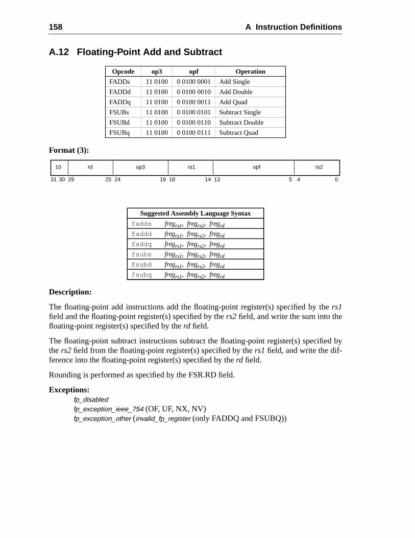
158 A Instruction Definitions
d by
A.12 Floating-Point Add and Subtract
Format (3):
Description:
The floating-point add instructions add the floating-point register(s) specified by thers1field and the floating-point register(s) specified by thers2 field, and write the sum into thefloating-point register(s) specified by therd field.
The floating-point subtract instructions subtract the floating-point register(s) specifiethers2 field from the floating-point register(s) specified by thers1 field, and write the dif-ference into the floating-point register(s) specified by therd field.
Rounding is performed as specified by the FSR.RD field.
Exceptions:fp_disabledfp_exception_ieee_754 (OF, UF, NX, NV)fp_exception_other (invalid_fp_register (only FADDQ and FSUBQ))
Opcode op3 opf Operation
FADDs 11 0100 0 0100 0001 Add Single
FADDd 11 0100 0 0100 0010 Add Double
FADDq 11 0100 0 0100 0011 Add Quad
FSUBs 11 0100 0 0100 0101 Subtract Single
FSUBd 11 0100 0 0100 0110 Subtract Double
FSUBq 11 0100 0 0100 0111 Subtract Quad
Suggested Assembly Language Syntax
fadds fregrs1, fregrs2, fregrd
faddd fregrs1, fregrs2, fregrd
faddq fregrs1, fregrs2, fregrd
fsubs fregrs1, fregrs2, fregrd
fsubd fregrs1, fregrs2, fregrd
fsubq fregrs1, fregrs2, fregrd
10 op3 rs2rd rs1
31 141924 18 13 02530 29 4
opf
5
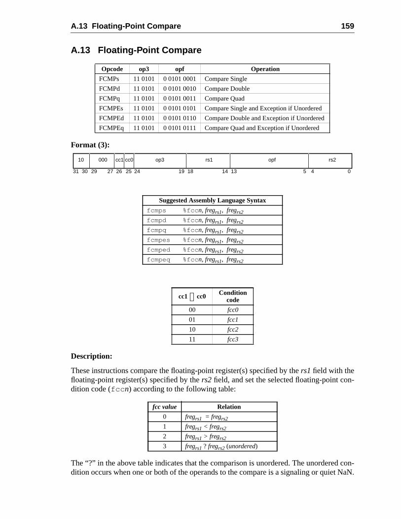
A.13 Floating-Point Compare 159
n-
con-NaN.
A.13 Floating-Point Compare
Format (3):
Description:
These instructions compare the floating-point register(s) specified by thers1field with thefloating-point register(s) specified by thers2 field, and set the selected floating-point codition code (fcc n) according to the following table:
The “?” in the above table indicates that the comparison is unordered. The unordereddition occurs when one or both of the operands to the compare is a signaling or quiet
Opcode op3 opf Operation
FCMPs 11 0101 0 0101 0001 Compare Single
FCMPd 11 0101 0 0101 0010 Compare Double
FCMPq 11 0101 0 0101 0011 Compare Quad
FCMPEs 11 0101 0 0101 0101 Compare Single and Exception if Unordered
FCMPEd 11 0101 0 0101 0110 Compare Double and Exception if Unordered
FCMPEq 11 0101 0 0101 0111 Compare Quad and Exception if Unordered
Suggested Assembly Language Syntax
fcmps %fcc n, fregrs1, fregrs2
fcmpd %fcc n, fregrs1, fregrs2
fcmpq %fcc n, fregrs1, fregrs2
fcmpes %fcc n, fregrs1, fregrs2
fcmped %fcc n, fregrs1, fregrs2
fcmpeq %fcc n, fregrs1, fregrs2
cc1 cc0 Conditioncode
00 fcc0
01 fcc1
10 fcc2
11 fcc3
fcc value Relation
0 fregrs1 = fregrs2
1 fregrs1 < fregrs2
2 fregrs1 > fregrs2
3 fregrs1 ? fregrs2 (unordered)
10 op3 rs2000 rs1
31 141924 18 13 02530 29 4
opf
52627
cc1 cc0
160 A Instruction Definitions
PEq)
pare
to
The “compare and cause exception if unordered” (FCMPEs, FCMPEd, and FCMinstructions cause an invalid (NV) exception if either operand is a NaN.
FCMP causes an invalid (NV) exception if either operand is a signaling NaN.
V8 Compatibility Note:Unlike SPARC-V8, SPARC-V9 does not require an instruction between a floating-point comoperation and a floating-point branch (FBfcc, FBPfcc).
V8 Compatibility Note:SPARC-V8 floating-point compare instructions are required to have a zero in ther[rd] field. InSPARC-V9, bits 26 and 25 of ther[rd] field are used to specify the floating-point condition codebe set. Legal SPARC-V8 code will work on SPARC-V9 because the zeroes in ther[rd] field areinterpreted asfcc0 , and the FBfcc instruction branches based onfcc0 .
Exceptions:fp_disabledfp_exception_ieee_754 (NV)fp_exception_other (invalid_fp_register (FCMPq, FCMPEq only))
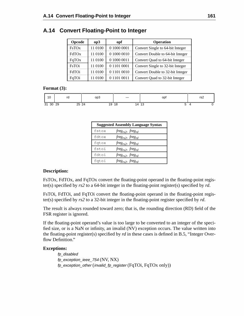
A.14 Convert Floating-Point to Integer 161
gis-
gis-
f the
peci-ntor-
A.14 Convert Floating-Point to Integer
Format (3):
Description:
FsTOx, FdTOx, and FqTOx convert the floating-point operand in the floating-point reter(s) specified byrs2 to a 64-bit integer in the floating-point register(s) specified byrd.
FsTOi, FdTOi, and FqTOi convert the floating-point operand in the floating-point reter(s) specified byrs2 to a 32-bit integer in the floating-point register specified byrd.
The result is always rounded toward zero; that is, the rounding direction (RD) field oFSR register is ignored.
If the floating-point operand’s value is too large to be converted to an integer of the sfied size, or is a NaN or infinity, an invalid (NV) exception occurs. The value written ithe floating-point register(s) specified byrd in these cases is defined in B.5, “Integer Oveflow Definition.”
Exceptions:fp_disabledfp_exception_ieee_754 (NV, NX)fp_exception_other (invalid_fp_register (FqTOi, FqTOx only))
Opcode op3 opf Operation
FsTOx 11 0100 0 1000 0001 Convert Single to 64-bit Integer
FdTOx 11 0100 0 1000 0010 Convert Double to 64-bit Integer
FqTOx 11 0100 0 1000 0011 Convert Quad to 64-bit Integer
FsTOi 11 0100 0 1101 0001 Convert Single to 32-bit Integer
FdTOi 11 0100 0 1101 0010 Convert Double to 32-bit Integer
FqTOi 11 0100 0 1101 0011 Convert Quad to 32-bit Integer
Suggested Assembly Language Syntax
fstox fregrs2, fregrd
fdtox fregrs2, fregrd
fqtox fregrs2, fregrd
fstoi fregrs2, fregrd
fdtoi fregrs2, fregrd
fqtoi fregrs2, fregrd
10 op3 rs2rd —
31 141924 18 13 02530 29 4
opf
5
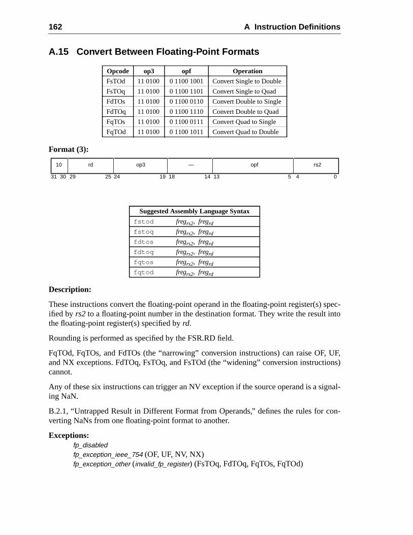
162 A Instruction Definitions
pec-nto
UF,ons)
gnal-
on-
A.15 Convert Between Floating-Point Formats
Format (3):
Description:
These instructions convert the floating-point operand in the floating-point register(s) sified by rs2 to a floating-point number in the destination format. They write the result ithe floating-point register(s) specified byrd.
Rounding is performed as specified by the FSR.RD field.
FqTOd, FqTOs, and FdTOs (the “narrowing” conversion instructions) can raise OF,and NX exceptions. FdTOq, FsTOq, and FsTOd (the “widening” conversion instructicannot.
Any of these six instructions can trigger an NV exception if the source operand is a siing NaN.
B.2.1, “Untrapped Result in Different Format from Operands,” defines the rules for cverting NaNs from one floating-point format to another.
Exceptions:fp_disabledfp_exception_ieee_754 (OF, UF, NV, NX)fp_exception_other (invalid_fp_register) (FsTOq, FdTOq, FqTOs, FqTOd)
Opcode op3 opf Operation
FsTOd 11 0100 0 1100 1001 Convert Single to Double
FsTOq 11 0100 0 1100 1101 Convert Single to Quad
FdTOs 11 0100 0 1100 0110 Convert Double to Single
FdTOq 11 0100 0 1100 1110 Convert Double to Quad
FqTOs 11 0100 0 1100 0111 Convert Quad to Single
FqTOd 11 0100 0 1100 1011 Convert Quad to Double
Suggested Assembly Language Syntax
fstod fregrs2, fregrd
fstoq fregrs2, fregrd
fdtos fregrs2, fregrd
fdtoq fregrs2, fregrd
fqtos fregrs2, fregrd
fqtod fregrs2, fregrd
10 op3 rs2rd —
31 141924 18 13 02530 29 4
opf
5
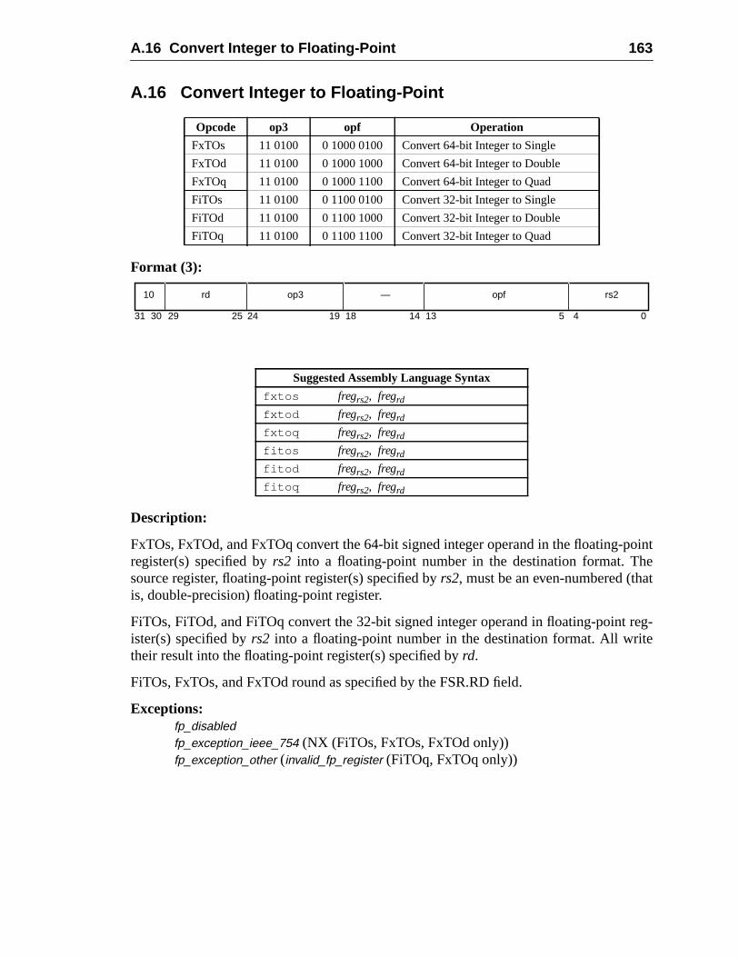
A.16 Convert Integer to Floating-Point 163
ointet
reg-e
A.16 Convert Integer to Floating-Point
Format (3):
Description:
FxTOs, FxTOd, and FxTOq convert the 64-bit signed integer operand in the floating-pregister(s) specified byrs2 into a floating-point number in the destination format. Thsource register, floating-point register(s) specified byrs2, must be an even-numbered (thais, double-precision) floating-point register.
FiTOs, FiTOd, and FiTOq convert the 32-bit signed integer operand in floating-pointister(s) specified byrs2 into a floating-point number in the destination format. All writtheir result into the floating-point register(s) specified byrd.
FiTOs, FxTOs, and FxTOd round as specified by the FSR.RD field.
Exceptions:fp_disabledfp_exception_ieee_754 (NX (FiTOs, FxTOs, FxTOd only))fp_exception_other (invalid_fp_register (FiTOq, FxTOq only))
Opcode op3 opf Operation
FxTOs 11 0100 0 1000 0100 Convert 64-bit Integer to Single
FxTOd 11 0100 0 1000 1000 Convert 64-bit Integer to Double
FxTOq 11 0100 0 1000 1100 Convert 64-bit Integer to Quad
FiTOs 11 0100 0 1100 0100 Convert 32-bit Integer to Single
FiTOd 11 0100 0 1100 1000 Convert 32-bit Integer to Double
FiTOq 11 0100 0 1100 1100 Convert 32-bit Integer to Quad
Suggested Assembly Language Syntax
fxtos fregrs2, fregrd
fxtod fregrs2, fregrd
fxtoq fregrs2, fregrd
fitos fregrs2, fregrd
fitod fregrs2, fregrd
fitoq fregrs2, fregrd
10 op3 rs2rd —
31 141924 18 13 02530 29 4
opf
5
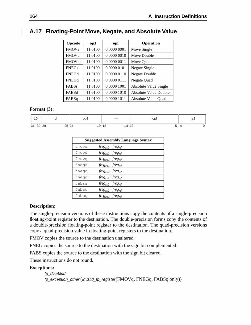
164 A Instruction Definitions
cisionts of
sions
A.17 Floating-Point Move, Negate, and Absolute Value
Format (3):
Description:
The single-precision versions of these instructions copy the contents of a single-prefloating-point register to the destination. The double-precision forms copy the contena double-precision floating-point register to the destination. The quad-precision vercopy a quad-precision value in floating-point registers to the destination.
FMOV copies the source to the destination unaltered.
FNEG copies the source to the destination with the sign bit complemented.
FABS copies the source to the destination with the sign bit cleared.
These instructions do not round.
Exceptions:fp_disabledfp_exception_other (invalid_fp_register(FMOVq, FNEGq, FABSq only))
Opcode op3 opf Operation
FMOVs 11 0100 0 0000 0001 Move Single
FMOVd 11 0100 0 0000 0010 Move Double
FMOVq 11 0100 0 0000 0011 Move Quad
FNEGs 11 0100 0 0000 0101 Negate Single
FNEGd 11 0100 0 0000 0110 Negate Double
FNEGq 11 0100 0 0000 0111 Negate Quad
FABSs 11 0100 0 0000 1001 Absolute Value Single
FABSd 11 0100 0 0000 1010 Absolute Value Double
FABSq 11 0100 0 0000 1011 Absolute Value Quad
Suggested Assembly Language Syntax
fmovs fregrs2, fregrd
fmovd fregrs2, fregrd
fmovq fregrs2, fregrd
fnegs fregrs2, fregrd
fnegd fregrs2, fregrd
fnegq fregrs2, fregrd
fabss fregrs2, fregrd
fabsd fregrs2, fregrd
fabsq fregrs2, fregrd
10 op3 rs2rd —
31 141924 18 13 02530 29 4
opf
5
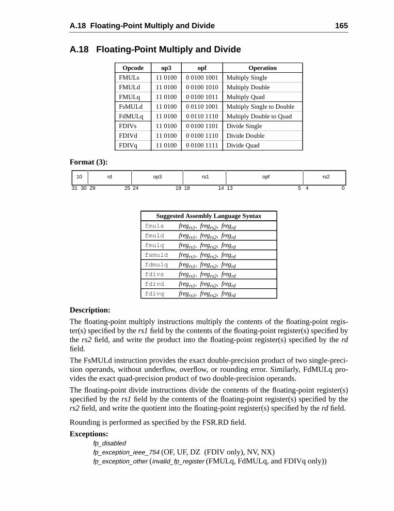
A.18 Floating-Point Multiply and Divide 165
is-by
eci-ro-
r(s)the
A.18 Floating-Point Multiply and Divide
Format (3):
Description:
The floating-point multiply instructions multiply the contents of the floating-point regter(s) specified by thers1field by the contents of the floating-point register(s) specifiedthe rs2 field, and write the product into the floating-point register(s) specified by therdfield.
The FsMULd instruction provides the exact double-precision product of two single-prsion operands, without underflow, overflow, or rounding error. Similarly, FdMULq pvides the exact quad-precision product of two double-precision operands.
The floating-point divide instructions divide the contents of the floating-point registespecified by thers1 field by the contents of the floating-point register(s) specified byrs2 field, and write the quotient into the floating-point register(s) specified by therd field.
Rounding is performed as specified by the FSR.RD field.
Exceptions:fp_disabledfp_exception_ieee_754 (OF, UF, DZ (FDIV only), NV, NX)fp_exception_other (invalid_fp_register (FMULq, FdMULq, and FDIVq only))
Opcode op3 opf Operation
FMULs 11 0100 0 0100 1001 Multiply Single
FMULd 11 0100 0 0100 1010 Multiply Double
FMULq 11 0100 0 0100 1011 Multiply Quad
FsMULd 11 0100 0 0110 1001 Multiply Single to Double
FdMULq 11 0100 0 0110 1110 Multiply Double to Quad
FDIVs 11 0100 0 0100 1101 Divide Single
FDIVd 11 0100 0 0100 1110 Divide Double
FDIVq 11 0100 0 0100 1111 Divide Quad
Suggested Assembly Language Syntax
fmuls fregrs1, fregrs2, fregrd
fmuld fregrs1, fregrs2, fregrd
fmulq fregrs1, fregrs2, fregrd
fsmuld fregrs1, fregrs2, fregrd
fdmulq fregrs1, fregrs2, fregrd
fdivs fregrs1, fregrs2, fregrd
fdivd fregrs1, fregrs2, fregrd
fdivq fregrs1, fregrs2, fregrd
10 op3 rs2rd rs1
31 141924 18 13 02530 29 4
opf
5
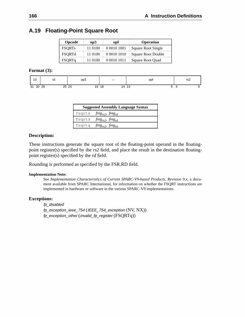
166 A Instruction Definitions
ating-g-
are
A.19 Floating-Point Square Root
Format (3):
Description:
These instructions generate the square root of the floating-point operand in the flopoint register(s) specified by thers2 field, and place the result in the destination floatinpoint register(s) specified by therd field.
Rounding is performed as specified by the FSR.RD field.
Implementation Note:SeeImplementation Characteristics of Current SPARC-V9-based Products, Revision 9.x, a docu-ment available from SPARC International, for information on whether the FSQRT instructionsimplemented in hardware or software in the various SPARC-V9 implementations.
Exceptions:fp_disabledfp_exception_ieee_754 (IEEE_754_exception (NV, NX))fp_exception_other (invalid_fp_register (FSQRTq))
Opcode op3 opf Operation
FSQRTs 11 0100 0 0010 1001 Square Root Single
FSQRTd 11 0100 0 0010 1010 Square Root Double
FSQRTq 11 0100 0 0010 1011 Square Root Quad
Suggested Assembly Language Syntax
fsqrts fregrs2, fregrd
fsqrtd fregrs2, fregrd
fsqrtq fregrs2, fregrd
10 op3 rs2rd —
31 141924 18 13 02530 29 4
opf
5
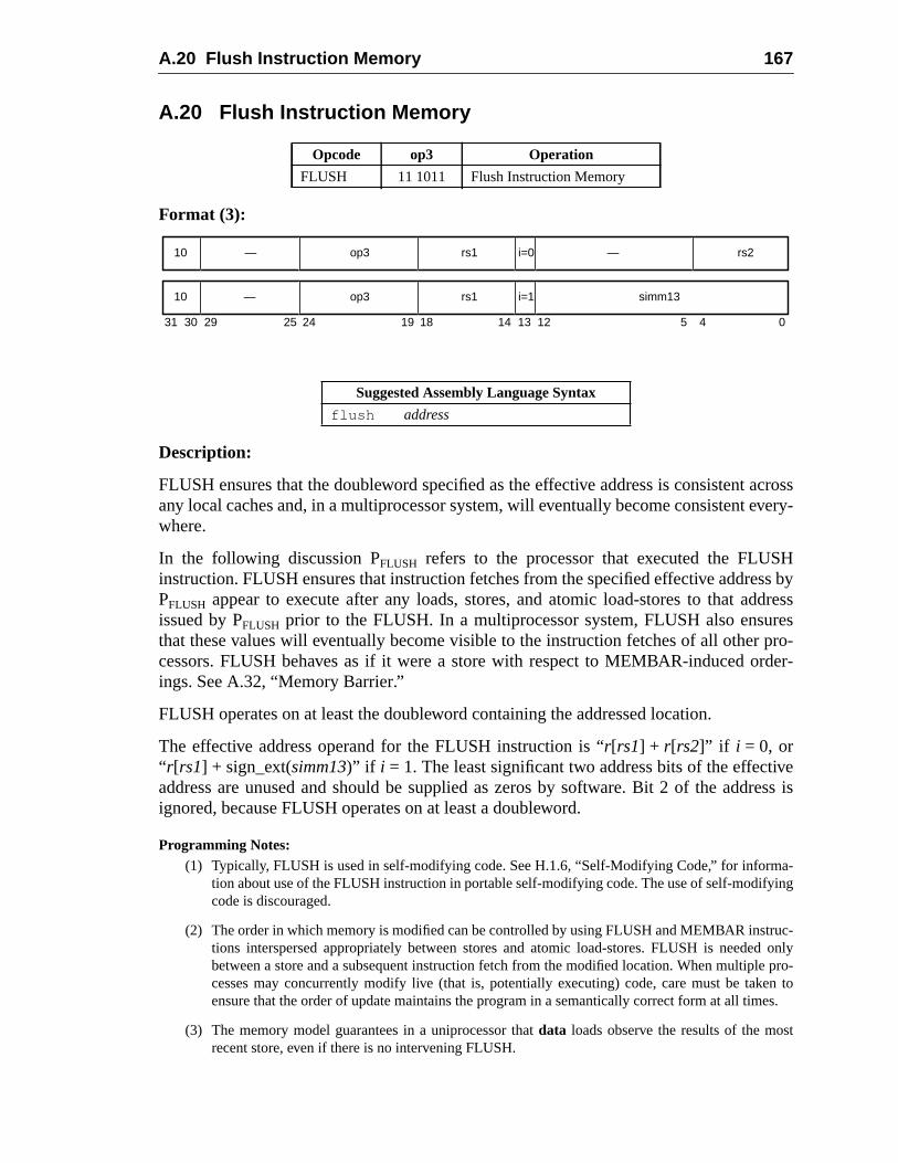
A.20 Flush Instruction Memory 167
acrossvery-
Hss byddressrespro-rder-
veress is
a-ing
uc-d onlye pro-en toes.
t
A.20 Flush Instruction Memory
Format (3):
Description:
FLUSH ensures that the doubleword specified as the effective address is consistentany local caches and, in a multiprocessor system, will eventually become consistent ewhere.
In the following discussion PFLUSH refers to the processor that executed the FLUSinstruction. FLUSH ensures that instruction fetches from the specified effective addrePFLUSH appear to execute after any loads, stores, and atomic load-stores to that aissued by PFLUSH prior to the FLUSH. In a multiprocessor system, FLUSH also ensuthat these values will eventually become visible to the instruction fetches of all othercessors. FLUSH behaves as if it were a store with respect to MEMBAR-induced oings. See A.32, “Memory Barrier.”
FLUSH operates on at least the doubleword containing the addressed location.
The effective address operand for the FLUSH instruction is “r[rs1] + r[rs2]” if i = 0, or“ r[rs1] + sign_ext(simm13)” if i = 1. The least significant two address bits of the effectiaddress are unused and should be supplied as zeros by software. Bit 2 of the addignored, because FLUSH operates on at least a doubleword.
Programming Notes:(1) Typically, FLUSH is used in self-modifying code. See H.1.6, “Self-Modifying Code,” for inform
tion about use of the FLUSH instruction in portable self-modifying code. The use of self-modifycode is discouraged.
(2) The order in which memory is modified can be controlled by using FLUSH and MEMBAR instrtions interspersed appropriately between stores and atomic load-stores. FLUSH is needebetween a store and a subsequent instruction fetch from the modified location. When multiplcesses may concurrently modify live (that is, potentially executing) code, care must be takensure that the order of update maintains the program in a semantically correct form at all tim
(3) The memory model guarantees in a uniprocessor thatdata loads observe the results of the mosrecent store, even if there is no intervening FLUSH.
Opcode op3 Operation
FLUSH 11 1011 Flush Instruction Memory
Suggested Assembly Language Syntax
flush address
31 24 02530 29 19 18
—10 op3 —
14 13 12 5 4
rs1 rs2i=0
10 op3 rs1 simm13i=1—
168 A Instruction Definitions
USHrefer-tivity.
pen-
ations,r-call-ions,ap to
anta-
(4) FLUSH may be time-consuming. Some implementations may trap rather than implement FLin hardware. In a multiprocessor configuration, FLUSH requires all processors that may beencing the addressed doubleword to flush their instruction caches, a potentially disruptive ac
(5) In a multiprocessor system, the time it takes for a FLUSH to take effect is implementation-dedent (impl. dep. #122). No mechanism is provided to ensure or test completion.
(6) Because FLUSH is designed to act on a doubleword, and because, on some implementFLUSH may trap to system software, it is recommended that system software provide a useable service routine for flushing arbitrarily sized regions of memory. On some implementatthis routine would issue a series of FLUSH instructions; on others, it might issue a single trsystem software that would then flush the entire region.
Implementation Notes:
(1) IMPL. DEP. #42: If FLUSH is not implemented in hardware, it causes an illegal_instructionexception and the function of FLUSH is performed by system software. Whether FLUSHtraps is implementation-dependent.
(2) The effect of a FLUSH instruction as observed from PFLUSH is immediate. Other processors inmultiprocessor system eventually will see the effect of the FLUSH, but the latency is implemetion-dependent (impl. dep. #122).
Exceptions:(none)
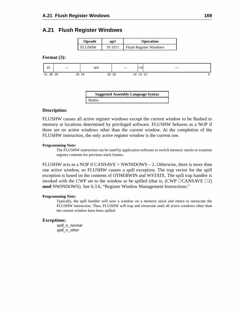
A.21 Flush Register Windows 169
d toP ifthe
mine
anspiller is
thean
A.21 Flush Register Windows
Format (3):
Description:
FLUSHW causes all active register windows except the current window to be flushememory at locations determined by privileged software. FLUSHW behaves as a NOthere are no active windows other than the current window. At the completion ofFLUSHW instruction, the only active register window is the current one.
Programming Note:The FLUSHW instruction can be used by application software to switch memory stacks or exaregister contents for previous stack frames.
FLUSHW acts as a NOP if CANSAVE = NWINDOWS – 2. Otherwise, there is more thone active window, so FLUSHW causes a spill exception. The trap vector for theexception is based on the contents of OTHERWIN and WSTATE. The spill trap handlinvoked with the CWP set to the window to be spilled (that is, (CWP+ CANSAVE + 2)mod NWINDOWS). See 6.3.6, “Register Window Management Instructions.”
Programming Note:Typically, the spill handler will save a window on a memory stack and return to reexecuteFLUSHW instruction. Thus, FLUSHW will trap and reexecute until all active windows other ththe current window have been spilled.
Exceptions:spill_n_normalspill_n_other
Opcode op3 Operation
FLUSHW 10 1011 Flush Register Windows
Suggested Assembly Language Syntax
flushw
31 24 02530 29 19 18
—10 op3 —
14 13 12
— i=0
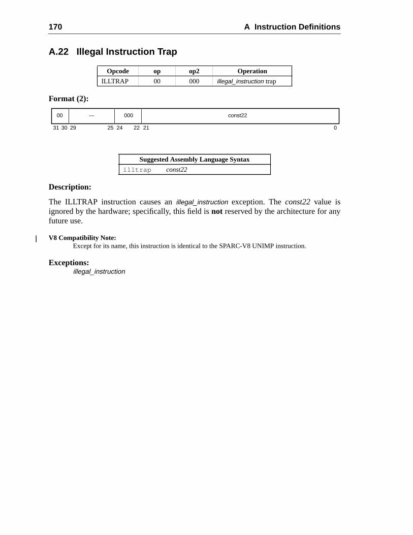
170 A Instruction Definitions
y
A.22 Illegal Instruction Trap
Format (2):
Description:
The ILLTRAP instruction causes anillegal_instruction exception. Theconst22value isignored by the hardware; specifically, this field isnot reserved by the architecture for anfuture use.
V8 Compatibility Note:Except for its name, this instruction is identical to the SPARC-V8 UNIMP instruction.
Exceptions:illegal_instruction
Opcode op op2 Operation
ILLTRAP 00 000 illegal_instruction trap
Suggested Assembly Language Syntax
illtrap const22
00 000 const22—
31 2124 02530 29 22
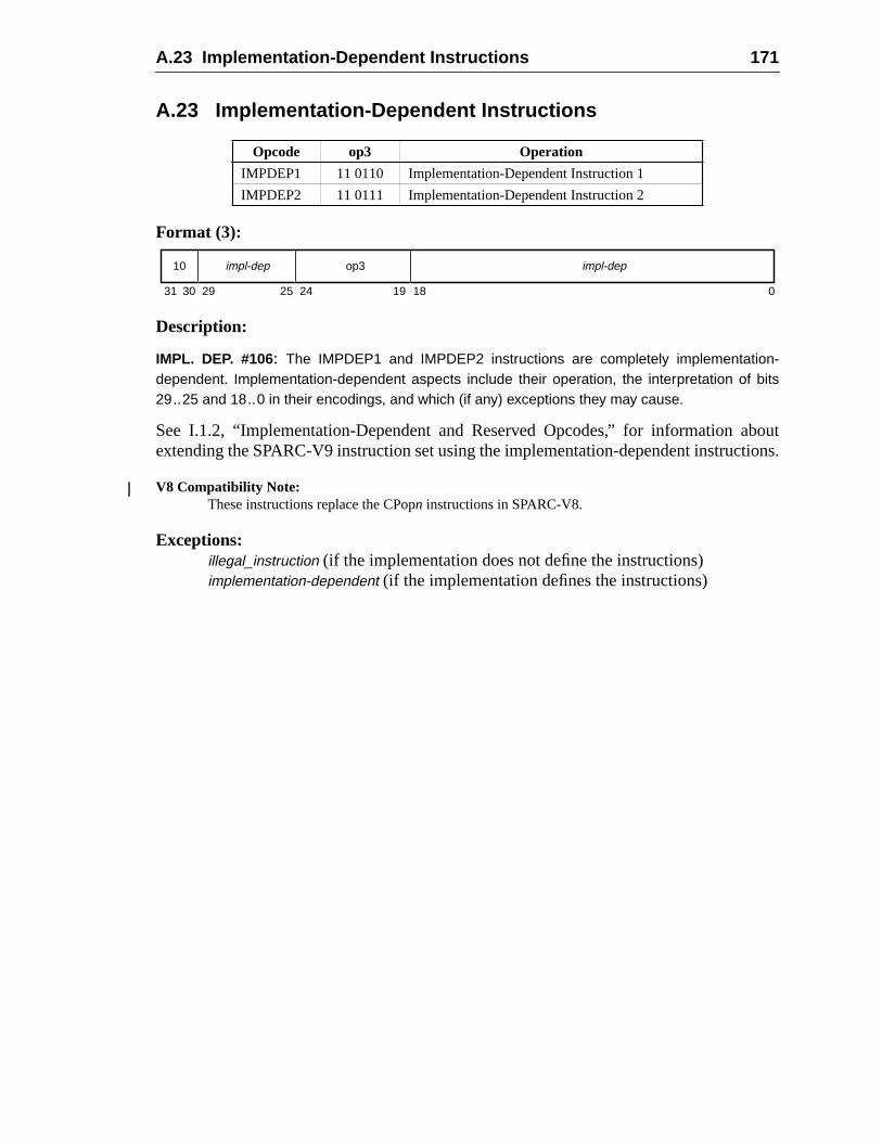
A.23 Implementation-Dependent Instructions 171
bouttions.
A.23 Implementation-Dependent Instructions
Format (3):
Description:
IMPL. DEP. #106: The IMPDEP1 and IMPDEP2 instructions are completely implementation-dependent. Implementation-dependent aspects include their operation, the interpretation of bits29..25 and 18..0 in their encodings, and which (if any) exceptions they may cause.
See I.1.2, “Implementation-Dependent and Reserved Opcodes,” for information aextending the SPARC-V9 instruction set using the implementation-dependent instruc
V8 Compatibility Note:These instructions replace the CPopn instructions in SPARC-V8.
Exceptions:illegal_instruction (if the implementation does not define the instructions)implementation-dependent (if the implementation defines the instructions)
Opcode op3 Operation
IMPDEP1 11 0110 Implementation-Dependent Instruction 1
IMPDEP2 11 0111 Implementation-Dependent Instruction 2
10 op3 impl-depimpl-dep
31 1824 02530 29 19
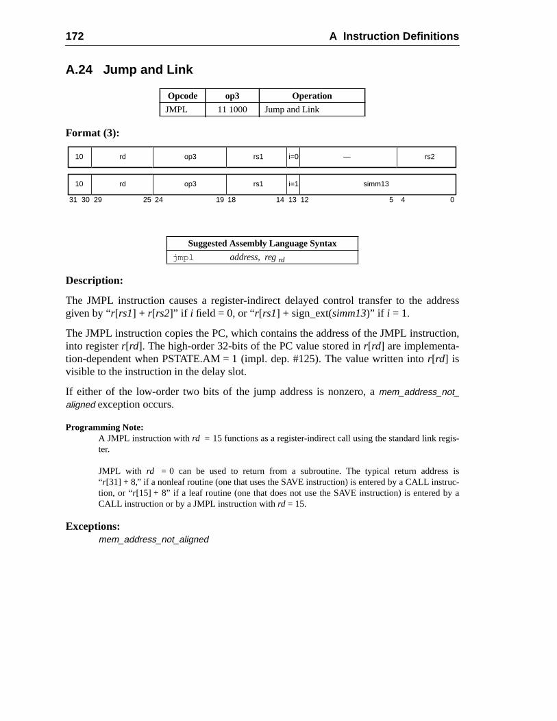
172 A Instruction Definitions
dress
tion,
is-
s isuc-y a
A.24 Jump and Link
Format (3):
Description:
The JMPL instruction causes a register-indirect delayed control transfer to the adgiven by “r[rs1] + r[rs2]” if i field = 0, or “r[rs1] + sign_ext(simm13)” if i = 1.
The JMPL instruction copies the PC, which contains the address of the JMPL instrucinto registerr[rd]. The high-order 32-bits of the PC value stored inr[rd] are implementa-tion-dependent when PSTATE.AM = 1 (impl. dep. #125). The value written intor[rd] isvisible to the instruction in the delay slot.
If either of the low-order two bits of the jump address is nonzero, amem_address_not_aligned exception occurs.
Programming Note:A JMPL instruction withrd = 15 functions as a register-indirect call using the standard link regter.
JMPL with rd = 0 can be used to return from a subroutine. The typical return addres“ r[31] + 8,” if a nonleaf routine (one that uses the SAVE instruction) is entered by a CALL instrtion, or “r[15] + 8” if a leaf routine (one that does not use the SAVE instruction) is entered bCALL instruction or by a JMPL instruction withrd = 15.
Exceptions:mem_address_not_aligned
Opcode op3 Operation
JMPL 11 1000 Jump and Link
Suggested Assembly Language Syntax
jmpl address, regrd
31 24 02530 29 19 18
rd10 op3
14 13 12 5 4
rs1 rs2i=0
rd10 op3 rs1 simm13i=1
—
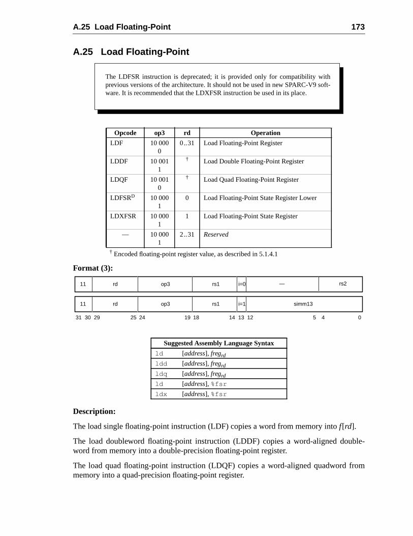
A.25 Load Floating-Point 173
le-
rom
A.25 Load Floating-Point
† Encoded floating-point register value, as described in 5.1.4.1
Format (3):
Description:
The load single floating-point instruction (LDF) copies a word from memory intof[rd].
The load doubleword floating-point instruction (LDDF) copies a word-aligned doubword from memory into a double-precision floating-point register.
The load quad floating-point instruction (LDQF) copies a word-aligned quadword fmemory into a quad-precision floating-point register.
Opcode op3 rd Operation
LDF 10 0000
0..31 Load Floating-Point Register
LDDF 10 0011
† Load Double Floating-Point Register
LDQF 10 0010
† Load Quad Floating-Point Register
LDFSRD 10 0001
0 Load Floating-Point State Register Lower
LDXFSR 10 0001
1 Load Floating-Point State Register
— 10 0001
2..31 Reserved
Suggested Assembly Language Syntax
ld [address], fregrd
ldd [address], fregrd
ldq [address], fregrd
ld [address], %fsr
ldx [address], %fsr
The LDFSR instruction is deprecated; it is provided only for compatibility withprevious versions of the architecture. It should not be used in new SPARC-V9 soft-ware. It is recommended that the LDXFSR instruction be used in its place.
31 24 02530 29 19 18 14 13 12 5 4
rd11 op3 rs1 simm13i=1
rd11 op3 rs1 i=0 — rs2
174 A Instruction Definitions
ruc-moryR.
onsmory
tionpro-
bledtruc-
ld notmula-of sin-e
The load floating-point state register lower instruction (LDFSR) waits for all FPop insttions that have not finished execution to complete, and then loads a word from meinto the lower 32 bits of the FSR. The upper 32 bits of FSR are unaffected by LDFS
The load floating-point state register instruction (LDXFSR) waits for all FPop instructithat have not finished execution to complete, and then loads a doubleword from meinto the FSR.
V8 Compatibility Note:SPARC-V9 supports two different instructions to load the FSR; the SPARC-V8 LDFSR instrucis defined to load only the lower 32 bits into the FSR, whereas LDXFSR allows SPARC-V9grams to load all 64 bits of the FSR.
Load floating-point instructions access the primary address space (ASI = 8016). The effec-tive address for these instructions is “r[rs1] + r[rs2]” if i = 0, or “r[rs1] + sign_ext(simm13)” if i = 1.
LDF, LDFSR, LDDF, and LDQF cause amem_address_not_aligned exception if the effec-tive memory address is not word-aligned; LDXFSR causes amem_address_not_alignedexception if the address is not doubleword-aligned. If the floating-point unit is not ena(per FPRS.FEF and PSTATE.PEF), or if no FPU is present, a load floating-point instion causes anfp_disabled exception.
IMPL. DEP. #109(1): LDDF requires only word alignment. However, if the effective address isword-aligned but not doubleword-aligned, LDDF may cause an LDDF_mem_address_not_alignedexception. In this case the trap handler software shall emulate the LDDF instruction and return.
IMPL. DEP. #111(1): LDQF requires only word alignment. However, if the effective address isword-aligned but not quadword-aligned, LDQF may cause an LDQF_mem_address_not_alignedexception. In this case the trap handler software shall emulate the LDQF instruction and return.
Programming Note:In SPARC-V8, some compilers issued sequences of single-precision loads when they coudetermine that double- or quadword operands were properly aligned. For SPARC-V9, since etion of misaligned loads is expected to be fast, it is recommended that compilers issue setsgle-precision loads only when they can determine that double- or quadword operands arnotproperly aligned.
Implementation Note:IMPL. DEP. #44: If a load floating-point instruction traps with any type of access error, thecontents of the destination floating-point register(s) remain unchanged or are undefined.
Exceptions:async_data_errorillegal_instruction (op3=2116 andrd = 2..31)fp_disabledLDDF_mem_address_not_aligned (LDDF only) (impl. dep. #109)LDQF_mem_address_not_aligned (LDQF only) (impl. dep. #111)fp_exception_other (invalid_fp_register (LDQF only))mem_address_not_aligneddata_access_MMU_missdata_access_exceptiondata_access_error

A.25 Load Floating-Point 175
data_access_protection
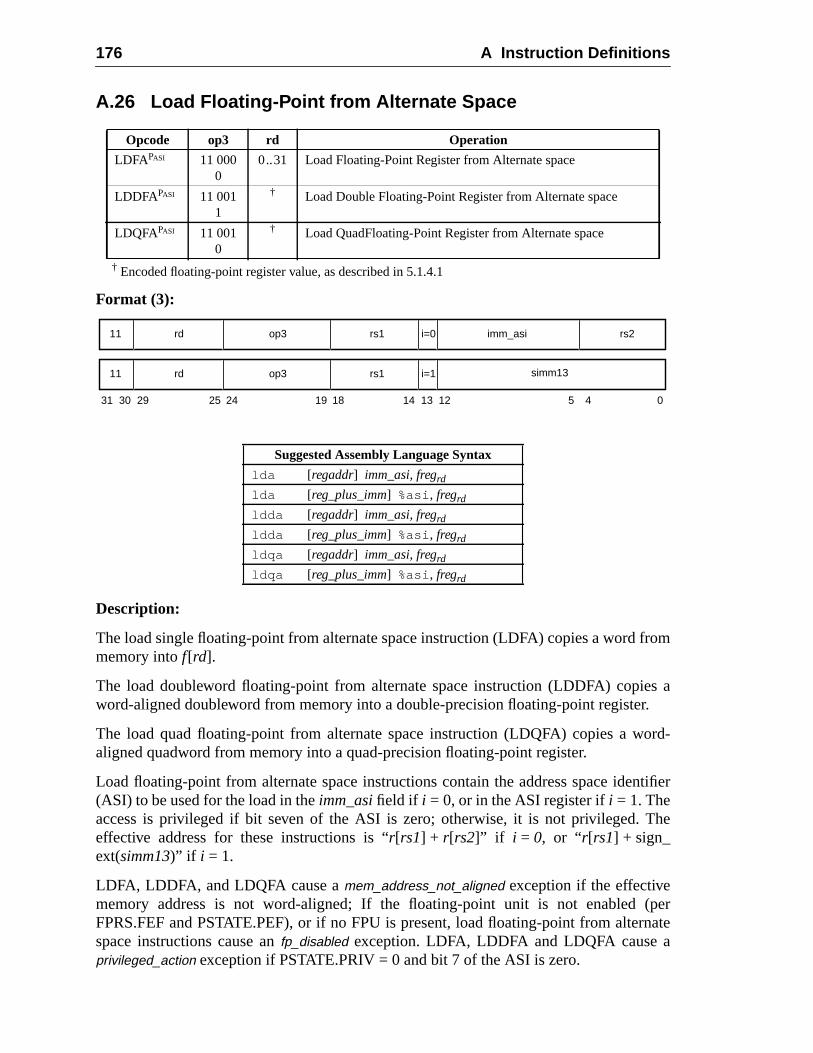
176 A Instruction Definitions
rom
s ar.
ord-
ntifier
The
(pernate
A.26 Load Floating-Point from Alternate Space
† Encoded floating-point register value, as described in 5.1.4.1
Format (3):
Description:
The load single floating-point from alternate space instruction (LDFA) copies a word fmemory intof[rd].
The load doubleword floating-point from alternate space instruction (LDDFA) copieword-aligned doubleword from memory into a double-precision floating-point registe
The load quad floating-point from alternate space instruction (LDQFA) copies a waligned quadword from memory into a quad-precision floating-point register.
Load floating-point from alternate space instructions contain the address space ide(ASI) to be used for the load in theimm_asifield if i = 0, or in the ASI register ifi = 1. Theaccess is privileged if bit seven of the ASI is zero; otherwise, it is not privileged.effective address for these instructions is “r[rs1] + r[rs2]” if i = 0, or “r[rs1] + sign_ext(simm13)” if i = 1.
LDFA, LDDFA, and LDQFA cause amem_address_not_aligned exception if the effectivememory address is not word-aligned; If the floating-point unit is not enabledFPRS.FEF and PSTATE.PEF), or if no FPU is present, load floating-point from alterspace instructions cause anfp_disabled exception. LDFA, LDDFA and LDQFA cause aprivileged_action exception if PSTATE.PRIV = 0 and bit 7 of the ASI is zero.
Opcode op3 rd Operation
LDFAPASI 11 0000
0..31 Load Floating-Point Register from Alternate space
LDDFAPASI 11 0011
† Load Double Floating-Point Register from Alternate space
LDQFAPASI 11 0010
† Load QuadFloating-Point Register from Alternate space
Suggested Assembly Language Syntax
lda [regaddr] imm_asi, fregrdlda [reg_plus_imm] %asi , fregrd
ldda [regaddr] imm_asi, fregrdldda [reg_plus_imm] %asi , fregrd
ldqa [regaddr] imm_asi, fregrdldqa [reg_plus_imm] %asi , fregrd
31 24 02530 29 19 18
rd11 op3 imm_asi
14 13 12 5 4
rs1 rs2i=0
rd11 op3 rs1 i=1 simm13
A.26 Load Floating-Point from Alternate Space 177
ld notmula-of sin-e
oint
IMPL. DEP. #109(2): LDDFA requires only word alignment. However, if the effective address isword-aligned but not doubleword-aligned, LDDFA may cause an LDDF_mem_address_not_aligned exception. In this case the trap handler software shall emulate the LDDF instruction andreturn.
IMPL. DEP. #111(2): LDQFA requires only word alignment. however, if the effective address isword-aligned but not quadword-aligned, LDQFA may cause an ldqf_mem_address_not_alignedexception. In this case the trap handler software shall emulate the LDQF instruction and return.
Programming Note:In SPARC-V8, some compilers issued sequences of single-precision loads when they coudetermine that double- or quadword operands were properly aligned. For SPARC-V9, since etion of mis-aligned loads is expected to be fast, it is recommended that compilers issue setsgle-precision loads only when they can determine that double- or quadword operands arnotproperly aligned.
Implementation Note:If a load floating-point instruction traps with any type of access error, the destination floating-pregister(s) either remain unchanged or are undefined. (impl. dep. #44)
Exceptions:async_data_errorfp_disabledLDDF_mem_address_not_aligned (LDDFA only) (impl. dep. #109)LDQF_mem_address_not_aligned (LDQFA only) (impl. dep. #111)fp_exception_other (invalid_fp_register (LDQFA only))mem_address_not_alignedprivileged_actiondata_access_MMU_missdata_access_exceptiondata_access_errordata_access_protection
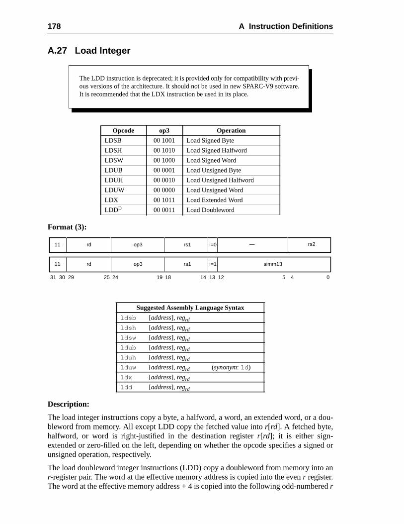
178 A Instruction Definitions
dou-
ed or
an
red
A.27 Load Integer
Format (3):
Description:
The load integer instructions copy a byte, a halfword, a word, an extended word, or ableword from memory. All except LDD copy the fetched value intor[rd]. A fetched byte,halfword, or word is right-justified in the destination registerr[rd]; it is either sign-extended or zero-filled on the left, depending on whether the opcode specifies a signunsigned operation, respectively.
The load doubleword integer instructions (LDD) copy a doubleword from memory intor-register pair. The word at the effective memory address is copied into the evenr register.The word at the effective memory address + 4 is copied into the following odd-number
Opcode op3 Operation
LDSB 00 1001 Load Signed Byte
LDSH 00 1010 Load Signed Halfword
LDSW 00 1000 Load Signed Word
LDUB 00 0001 Load Unsigned Byte
LDUH 00 0010 Load Unsigned Halfword
LDUW 00 0000 Load Unsigned Word
LDX 00 1011 Load Extended Word
LDDD 00 0011 Load Doubleword
Suggested Assembly Language Syntax
ldsb [address], regrd
ldsh [address], regrd
ldsw [address], regrd
ldub [address], regrd
lduh [address], regrd
lduw [address], regrd (synonym: ld )
ldx [address], regrd
ldd [address], regrd
The LDD instruction is deprecated; it is provided only for compatibility with previ-ous versions of the architecture. It should not be used in new SPARC-V9 software.It is recommended that the LDX instruction be used in its place.
31 24 02530 29 19 18 14 13 12 5 4
rd11 op3 rs1 simm13i=1
rd11 op3 rs1 i=0 — rs2
A.27 Load Integer 179
oft-gned
rates
-
9to emu-
rder
n is
register. The upper 32 bits of both the even-numbered and odd-numberedr registers arezero-filled. Note that a load doubleword withrd = 0 modifies onlyr[1]. The least signifi-cant bit of therd field in an LDD instruction is unused and should be set to zero by sware. An attempt to execute a load doubleword instruction that refers to a misali(odd-numbered) destination register causes anillegal_instruction exception.
IMPL. DEP. #107(1): It is implementation-dependent whether LDD is implemented in hardware. Ifnot, an attempt to execute it will cause an unimplemented_ldd exception.
Load integer instructions access the primary address space (ASI = 8016). The effectiveaddress is “r[rs1] + r[rs2]” if i = 0, or “r[rs1] + sign_ext(simm13)” if i = 1.
A successful load (notably, load extended and load doubleword) instruction opeatomically.
LDUH and LDSH cause amem_address_not_aligned exception if the address is not halfword-aligned. LDUW and LDSW cause amem_address_not_aligned exception if the effec-tive address is not word-aligned. LDX and LDD cause amem_address_not_alignedexception if the address is not doubleword-aligned.
Programming Note:LDD is provided for compatibility with SPARC-V8. It may execute slowly on SPARC-Vmachines because of data path and register-access difficulties. In some systems it may traplation code. It is suggested that programmers and compilers avoid using these instructions.
If LDD is emulated in software, an LDX instruction should be used for the memory access in oto preserve atomicity.
V8 Compatibility Note:The SPARC-V8 LD instruction has been renamed LDUW in SPARC-V9. The LDSW instructionew in SPARC-V9.
Exceptions:async_data_errorunimplemented_LDD (LDD only (impl. dep. #107))illegal_instruction (LDD with oddrd)mem_address_not_aligned (all except LDSB, LDUB)data_access_exceptiondata_access_protectiondata_access_MMU_missdata_access_error
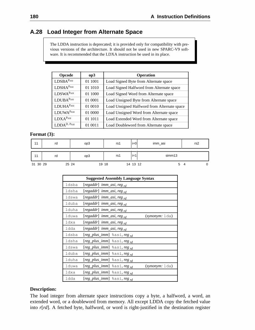
180 A Instruction Definitions
d, anlue
ter
A.28 Load Integer from Alternate Space
Format (3):
Description:The load integer from alternate space instructions copy a byte, a halfword, a worextended word, or a doubleword from memory. All except LDDA copy the fetched vainto r[rd]. A fetched byte, halfword, or word is right-justified in the destination regis
Opcode op3 Operation
LDSBAPASI 01 1001 Load Signed Byte from Alternate space
LDSHAPASI 01 1010 Load Signed Halfword from Alternate space
LDSWAPASI 01 1000 Load Signed Word from Alternate space
LDUBAPASI 01 0001 Load Unsigned Byte from Alternate space
LDUHAPASI 01 0010 Load Unsigned Halfword from Alternate space
LDUWAPASI 01 0000 Load Unsigned Word from Alternate space
LDXA PASI 01 1011 Load Extended Word from Alternate space
LDDAD, PASI 01 0011 Load Doubleword from Alternate space
Suggested Assembly Language Syntax
ldsba [regaddr] imm_asi, reg rd
ldsha [regaddr] imm_asi, reg rd
ldswa [regaddr] imm_asi, reg rd
lduba [regaddr] imm_asi, reg rd
lduha [regaddr] imm_asi, reg rd
lduwa [regaddr] imm_asi, reg rd (synonym:lda )
ldxa [regaddr] imm_asi, reg rd
ldda [regaddr] imm_asi, reg rd
ldsba [reg_plus_imm] %asi , reg rd
ldsha [reg_plus_imm] %asi , reg rd
ldswa [reg_plus_imm] %asi , reg rd
lduba [reg_plus_imm] %asi , reg rd
lduha [reg_plus_imm] %asi , reg rd
lduwa [reg_plus_imm] %asi , reg rd (synonym:lda )
ldxa [reg_plus_imm] %asi , reg rd
ldda [reg_plus_imm] %asi , reg rd
The LDDA instruction is deprecated; it is provided only for compatibility with pre-vious versions of the architecture. It should not be used in new SPARC-V9 soft-ware. It is recommended that the LDXA instruction be used in its place.
31 24 02530 29 19 18
rd11 op3 imm_asi
14 13 12 5 4
rs1 rs2i=0
rd11 op3 rs1 i=1 simm13
A.28 Load Integer from Alternate Space 181
code
ble-is
intond
n that
ntifier
The
rates
t
9to emu-
s in
uc-
r[rd]; it is either sign-extended or zero-filled on the left, depending on whether the opspecifies a signed or unsigned operation, respectively.
The load doubleword integer from alternate space instruction (LDDA) copies a douword from memory into anr-register pair. The word at the effective memory addresscopied into the evenr register. The word at the effective memory address + 4 is copiedthe following odd-numberedr register. The upper 32 bits of both the even-numbered aodd-numberedr registers are zero-filled. Note that a load doubleword withrd = 0 modifiesonly r[1]. The least significant bit of therd field in an LDDA instruction is unused andshould be set to zero by software. An attempt to execute a load doubleword instructiorefers to a misaligned (odd-numbered) destination register causes anillegal_instructionexception.
IMPL. DEP. #107(2): It is implementation-dependent whether LDDA is implemented in hardware. Ifnot, an attempt to execute it will cause an unimplemented_ldd exception.
The load integer from alternate space instructions contain the address space ide(ASI) to be used for the load in theimm_asifield if i = 0, or in the ASI register ifi = 1. Theaccess is privileged if bit seven of the ASI is zero; otherwise, it is not privileged.effective address for these instructions is “r[rs1] + r[rs2]” if i = 0, or “r[rs1] + sign_ext(simm13)” if i = 1.
A successful load (notably, load extended and load doubleword) instruction opeatomically.
LDUHA, and LDSHA cause amem_address_not_aligned exception if the address is nohalfword-aligned. LDUWA and LDSWA cause amem_address_not_aligned exception ifthe effective address is not word-aligned; LDXA and LDDA cause amem_address_not_aligned exception if the address is not doubleword-aligned.
These instructions cause aprivileged_action exception if PSTATE.PRIV = 0 and bit 7 of theASI is zero.
Programming Note:LDDA is provided for compatibility with SPARC-V8. It may execute slowly on SPARC-Vmachines because of data path and register-access difficulties. In some systems it may traplation code. It is suggested that programmers and compilers avoid using this instruction.
If LDDA is emulated in software, an LDXA instruction should be used for the memory accesorder to preserve atomicity.
V8 Compatibility Note:The SPARC-V8 instruction LDA has been renamed LDUWA in SPARC-V9. The LDSWA instrtion is new in SPARC-V9.
Exceptions:async_data_errorprivileged_actionunimplemented_LDD (LDDA only (impl. dep. #107))illegal_instruction (LDDA with odd rd)mem_address_not_aligned (all except LDSBA and LDUBA)data_access_exceptiondata_access_protectiondata_access_MMU_missdata_access_error
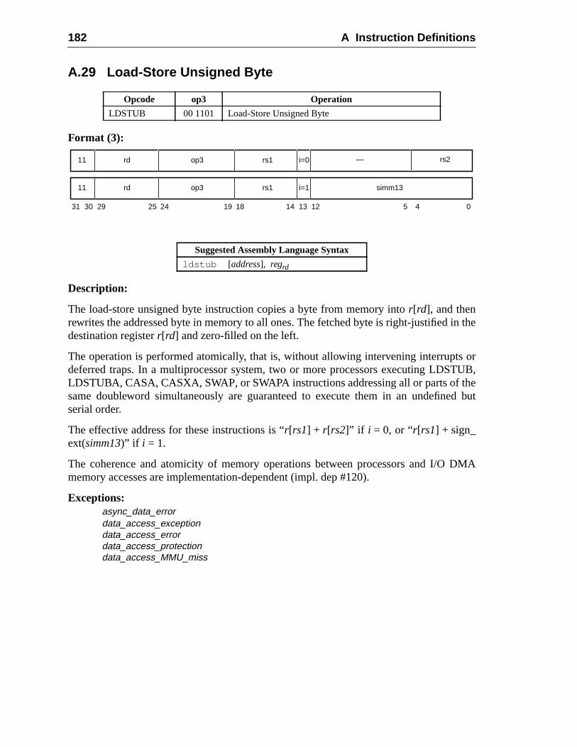
182 A Instruction Definitions
in the
s orTUB,heed but
DMA
A.29 Load-Store Unsigned Byte
Format (3):
Description:
The load-store unsigned byte instruction copies a byte from memory intor[rd], and thenrewrites the addressed byte in memory to all ones. The fetched byte is right-justifieddestination registerr[rd] and zero-filled on the left.
The operation is performed atomically, that is, without allowing intervening interruptdeferred traps. In a multiprocessor system, two or more processors executing LDSLDSTUBA, CASA, CASXA, SWAP, or SWAPA instructions addressing all or parts of tsame doubleword simultaneously are guaranteed to execute them in an undefinserial order.
The effective address for these instructions is “r[rs1] + r[rs2]” if i = 0, or “r[rs1] + sign_ext(simm13)” if i = 1.
The coherence and atomicity of memory operations between processors and I/Omemory accesses are implementation-dependent (impl. dep #120).
Exceptions:async_data_errordata_access_exceptiondata_access_errordata_access_protectiondata_access_MMU_miss
Opcode op3 Operation
LDSTUB 00 1101 Load-Store Unsigned Byte
Suggested Assembly Language Syntax
ldstub [address], regrd
31 24 02530 29 19 18 14 13 12 5 4
rd11 op3 rs1 simm13i=1
rd11 op3 rs1 i=0 — rs2
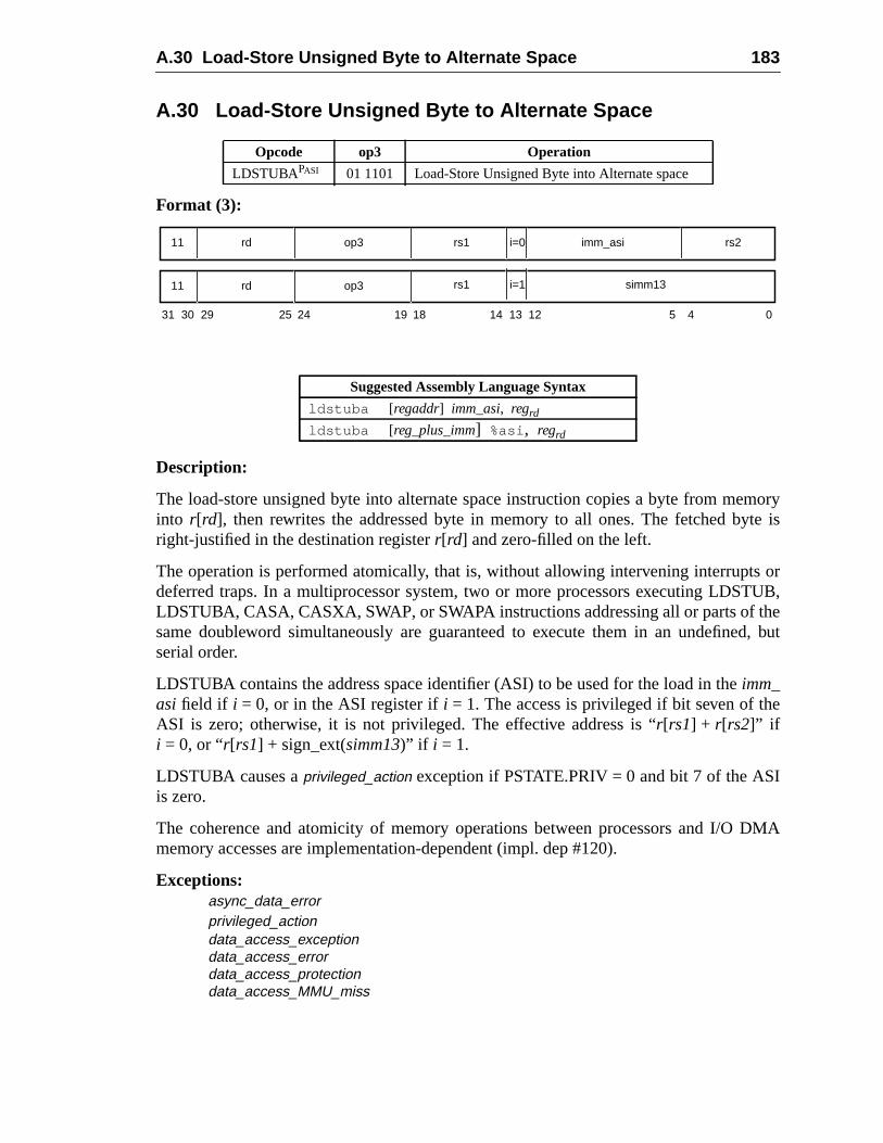
A.30 Load-Store Unsigned Byte to Alternate Space 183
moryte is
s orTUB,hed, but
e
I
DMA
A.30 Load-Store Unsigned Byte to Alternate Space
Format (3):
Description:
The load-store unsigned byte into alternate space instruction copies a byte from meinto r[rd], then rewrites the addressed byte in memory to all ones. The fetched byright-justified in the destination registerr[rd] and zero-filled on the left.
The operation is performed atomically, that is, without allowing intervening interruptdeferred traps. In a multiprocessor system, two or more processors executing LDSLDSTUBA, CASA, CASXA, SWAP, or SWAPA instructions addressing all or parts of tsame doubleword simultaneously are guaranteed to execute them in an undefineserial order.
LDSTUBA contains the address space identifier (ASI) to be used for the load in theimm_asi field if i = 0, or in the ASI register ifi = 1. The access is privileged if bit seven of thASI is zero; otherwise, it is not privileged. The effective address is “r[rs1] + r[rs2]” ifi = 0, or “r[rs1] + sign_ext(simm13)” if i = 1.
LDSTUBA causes aprivileged_action exception if PSTATE.PRIV = 0 and bit 7 of the ASis zero.
The coherence and atomicity of memory operations between processors and I/Omemory accesses are implementation-dependent (impl. dep #120).
Exceptions:async_data_errorprivileged_actiondata_access_exceptiondata_access_errordata_access_protectiondata_access_MMU_miss
Opcode op3 Operation
LDSTUBAPASI 01 1101 Load-Store Unsigned Byte into Alternate space
Suggested Assembly Language Syntax
ldstuba [regaddr] imm_asi, regrd
ldstuba [reg_plus_imm] %asi , regrd
31 24 02530 29 19 18
rd11 op3 imm_asi
14 13 12 5 4
rs1 rs2i=0
rd11 op3 rs1 i=1 simm13
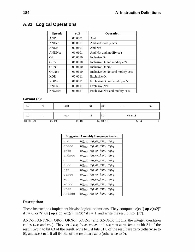
184 A Instruction Definitions
on
o
A.31 Logical Operations
Format (3):
Description:
These instructions implement bitwise logical operations. They compute “r[rs1] op r[rs2]”if i = 0, or “r[rs1] op sign_ext(simm13)” if i = 1, and write the result intor[rd].
ANDcc, ANDNcc, ORcc, ORNcc, XORcc, and XNORcc modify the integer conditicodes (icc andxcc). They seticc.v, icc.c, xcc.v, andxcc.c to zero,icc.n to bit 31 of theresult,xcc.nto bit 63 of the result,icc.zto 1 if bits 31:0 of the result are zero (otherwise t0), andxcc.z to 1 if all 64 bits of the result are zero (otherwise to 0).
Opcode op3 Operation
AND 00 0001 And
ANDcc 01 0001 And and modify cc’s
ANDN 00 0101 And Not
ANDNcc 01 0101 And Not and modify cc’s
OR 00 0010 Inclusive Or
ORcc 01 0010 Inclusive Or and modify cc’s
ORN 00 0110 Inclusive Or Not
ORNcc 01 0110 Inclusive Or Not and modify cc’s
XOR 00 0011 Exclusive Or
XORcc 01 0011 Exclusive Or and modify cc’s
XNOR 00 0111 Exclusive Nor
XNORcc 01 0111 Exclusive Nor and modify cc’s
Suggested Assembly Language Syntax
and regrs1, reg_or_imm, regrd
andcc regrs1, reg_or_imm, regrd
andn regrs1, reg_or_imm, regrd
andncc regrs1, reg_or_imm, regrd
or regrs1, reg_or_imm, regrd
orcc regrs1, reg_or_imm, regrd
orn regrs1, reg_or_imm, regrd
orncc regrs1, reg_or_imm, regrd
xor regrs1, reg_or_imm, regrd
xorcc regrs1, reg_or_imm, regrd
xnor regrs1, reg_or_imm, regrd
xnorcc regrs1, reg_or_imm, regrd
31 24 02530 29 19 18
rd10 op3 —
14 13 12 5 4
rs1 rs2i=0
rd10 op3 rs1 simm13i=1
A.31 Logical Operations 185
ply-
ec-
ANDN, ANDNcc, ORN, and ORNcc logically negate their second operand before aping the main (AND or OR) operation.
Programming Note:XNOR and XNORcc are identical to the XOR-Not and XOR-Not-cc logical operations, resptively.
Exceptions:(none)
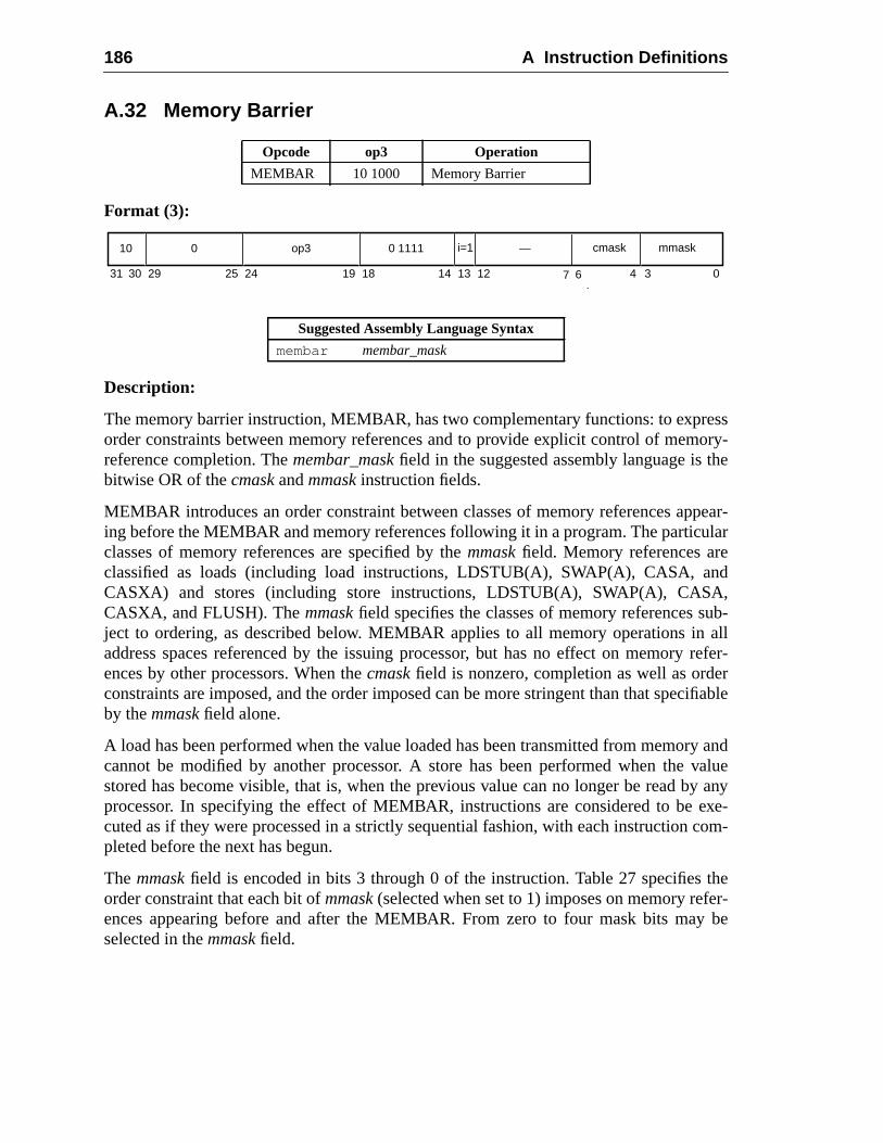
186 A Instruction Definitions
ressory-
he
pear-ular
ndA,ub-
allrefer-
rcifiable
ry andvaluey any
exe-com-
theer-y be
A.32 Memory Barrier
Format (3):
Description:
The memory barrier instruction, MEMBAR, has two complementary functions: to exporder constraints between memory references and to provide explicit control of memreference completion. Themembar_maskfield in the suggested assembly language is tbitwise OR of thecmask andmmask instruction fields.
MEMBAR introduces an order constraint between classes of memory references aping before the MEMBAR and memory references following it in a program. The particclasses of memory references are specified by themmaskfield. Memory references areclassified as loads (including load instructions, LDSTUB(A), SWAP(A), CASA, aCASXA) and stores (including store instructions, LDSTUB(A), SWAP(A), CASCASXA, and FLUSH). Themmaskfield specifies the classes of memory references sject to ordering, as described below. MEMBAR applies to all memory operations inaddress spaces referenced by the issuing processor, but has no effect on memoryences by other processors. When thecmaskfield is nonzero, completion as well as ordeconstraints are imposed, and the order imposed can be more stringent than that speby themmask field alone.
A load has been performed when the value loaded has been transmitted from memocannot be modified by another processor. A store has been performed when thestored has become visible, that is, when the previous value can no longer be read bprocessor. In specifying the effect of MEMBAR, instructions are considered to becuted as if they were processed in a strictly sequential fashion, with each instructionpleted before the next has begun.
The mmaskfield is encoded in bits 3 through 0 of the instruction. Table 27 specifiesorder constraint that each bit ofmmask(selected when set to 1) imposes on memory refences appearing before and after the MEMBAR. From zero to four mask bits maselected in themmask field.
Opcode op3 Operation
MEMBAR 10 1000 Memory Barrier
Suggested Assembly Language Syntax
membar membar_mask
31 141924 18 13 12 02530 29
10 0 op3 0 1111 i=1 —
4 3
mmask
6
4
7
cmask
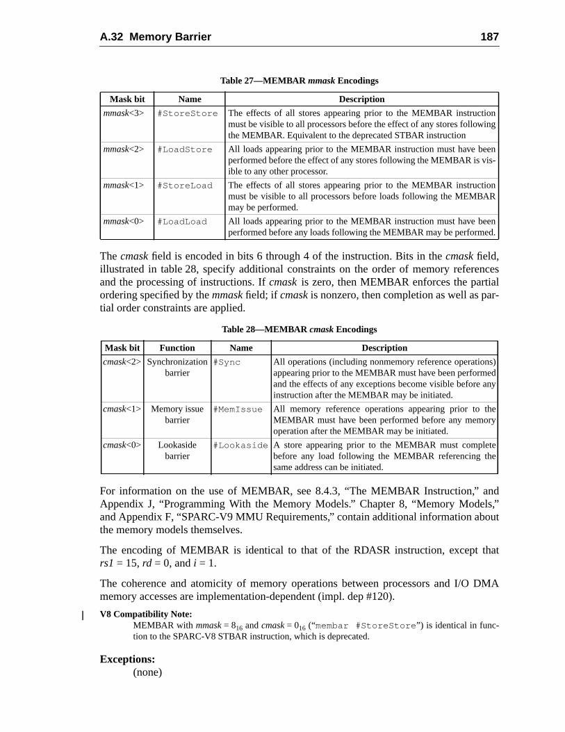
A.32 Memory Barrier 187
nceslr-
nds,”out
hat
DMA
nng
n-
n
n.
)dny
ey
Thecmaskfield is encoded in bits 6 through 4 of the instruction. Bits in thecmaskfield,illustrated in table 28, specify additional constraints on the order of memory refereand the processing of instructions. Ifcmaskis zero, then MEMBAR enforces the partiaordering specified by themmaskfield; if cmaskis nonzero, then completion as well as patial order constraints are applied.
For information on the use of MEMBAR, see 8.4.3, “The MEMBAR Instruction,” aAppendix J, “Programming With the Memory Models.” Chapter 8, “Memory Modeland Appendix F, “SPARC-V9 MMU Requirements,” contain additional information abthe memory models themselves.
The encoding of MEMBAR is identical to that of the RDASR instruction, except trs1 = 15,rd = 0, and i = 1.
The coherence and atomicity of memory operations between processors and I/Omemory accesses are implementation-dependent (impl. dep #120).
V8 Compatibility Note:MEMBAR with mmask= 816 andcmask= 016 (“membar #StoreStore ”) is identical in func-tion to the SPARC-V8 STBAR instruction, which is deprecated.
Exceptions:(none)
Table 27—MEMBAR mmask Encodings
Mask bit Name Description
mmask<3> #StoreStore The effects of all stores appearing prior to the MEMBAR instructiomust be visible to all processors before the effect of any stores followithe MEMBAR. Equivalent to the deprecated STBAR instruction
mmask<2> #LoadStore All loads appearing prior to the MEMBAR instruction must have beeperformed before the effect of any stores following the MEMBAR is visible to any other processor.
mmask<1> #StoreLoad The effects of all stores appearing prior to the MEMBAR instructiomust be visible to all processors before loads following the MEMBARmay be performed.
mmask<0> #LoadLoad All loads appearing prior to the MEMBAR instruction must have beeperformed before any loads following the MEMBAR may be performed
Table 28—MEMBAR cmask Encodings
Mask bit Function Name Description
cmask<2> Synchronizationbarrier
#Sync All operations (including nonmemory reference operationsappearing prior to the MEMBAR must have been performeand the effects of any exceptions become visible before ainstruction after the MEMBAR may be initiated.
cmask<1> Memory issuebarrier
#MemIssue All memory reference operations appearing prior to thMEMBAR must have been performed before any memoroperation after the MEMBAR may be initiated.
cmask<0> Lookasidebarrier
#Lookaside A store appearing prior to the MEMBAR must completebefore any load following the MEMBAR referencing thesame address can be initiated.
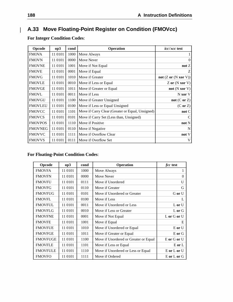
188 A Instruction Definitions
C
A.33 Move Floating-Point Register on Condition (FMOVcc)
For Integer Condition Codes:
For Floating-Point Condition Codes:
Opcode op3 cond Operation icc/xcc test
FMOVA 11 0101 1000 Move Always 1
FMOVN 11 0101 0000 Move Never 0
FMOVNE 11 0101 1001 Move if Not Equal not Z
FMOVE 11 0101 0001 Move if Equal Z
FMOVG 11 0101 1010 Move if Greater not (Z or (N xor V))
FMOVLE 11 0101 0010 Move if Less or Equal Zor (N xor V)
FMOVGE 11 0101 1011 Move if Greater or Equal not (N xor V)
FMOVL 11 0101 0011 Move if Less N xor V
FMOVGU 11 0101 1100 Move if Greater Unsigned not (C or Z)
FMOVLEU 11 0101 0100 Move if Less or Equal Unsigned (C or Z)
FMOVCC 11 0101 1101 Move if Carry Clear(Greater or Equal, Unsigned) not C
FMOVCS 11 0101 0101 Move if Carry Set (Less than, Unsigned)
FMOVPOS 11 0101 1110 Move if Positive not N
FMOVNEG 11 0101 0110 Move if Negative N
FMOVVC 11 0101 1111 Move if Overflow Clear not V
FMOVVS 11 0101 0111 Move if Overflow Set V
Opcode op3 cond Operation fcc test
FMOVFA 11 0101 1000 Move Always 1
FMOVFN 11 0101 0000 Move Never 0
FMOVFU 11 0101 0111 Move if Unordered U
FMOVFG 11 0101 0110 Move if Greater G
FMOVFUG 11 0101 0101 Move if Unordered or Greater Gor U
FMOVFL 11 0101 0100 Move if Less L
FMOVFUL 11 0101 0011 Move if Unordered or Less Lor U
FMOVFLG 11 0101 0010 Move if Less or Greater Lor G
FMOVFNE 11 0101 0001 Move if Not Equal Lor G or U
FMOVFE 11 0101 1001 Move if Equal E
FMOVFUE 11 0101 1010 Move if Unordered or Equal Eor U
FMOVFGE 11 0101 1011 Move if Greater or Equal Eor G
FMOVFUGE 11 0101 1100 Move if Unordered or Greater or Equal Eor G or U
FMOVFLE 11 0101 1101 Move if Less or Equal Eor L
FMOVFULE 11 0101 1110 Move if Unordered or Less or Equal Eor L or U
FMOVFO 11 0101 1111 Move if Ordered Eor L or G
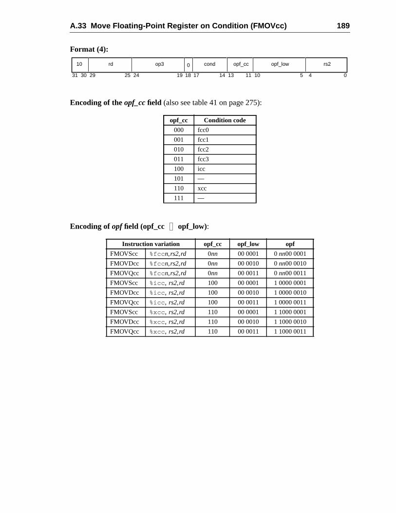
A.33 Move Floating-Point Register on Condition (FMOVcc) 189
Format (4):
Encoding of the opf_cc field (also see table 41 on page 275):
Encoding of opf field (opf_cc opf_low):
opf_cc Condition code
000 fcc0
001 fcc1
010 fcc2
011 fcc3
100 icc
101 —
110 xcc
111 —
Instruction variation opf_cc opf_low opf
FMOVScc %fcc n,rs2,rd 0nn 00 0001 0nn00 0001
FMOVDcc %fcc n,rs2,rd 0nn 00 0010 0nn00 0010
FMOVQcc %fcc n,rs2,rd 0nn 00 0011 0nn00 0011
FMOVScc %icc , rs2,rd 100 00 0001 1 0000 0001
FMOVDcc %icc , rs2,rd 100 00 0010 1 0000 0010
FMOVQcc %icc , rs2,rd 100 00 0011 1 0000 0011
FMOVScc %xcc, rs2,rd 110 00 0001 1 1000 0001
FMOVDcc %xcc, rs2,rd 110 00 0010 1 1000 0010
FMOVQcc %xcc, rs2,rd 110 00 0011 1 1000 0011
31 1924 18 1314 11 5 4 010172530 29
10 rd op3 cond opf_cc opf_low rs20
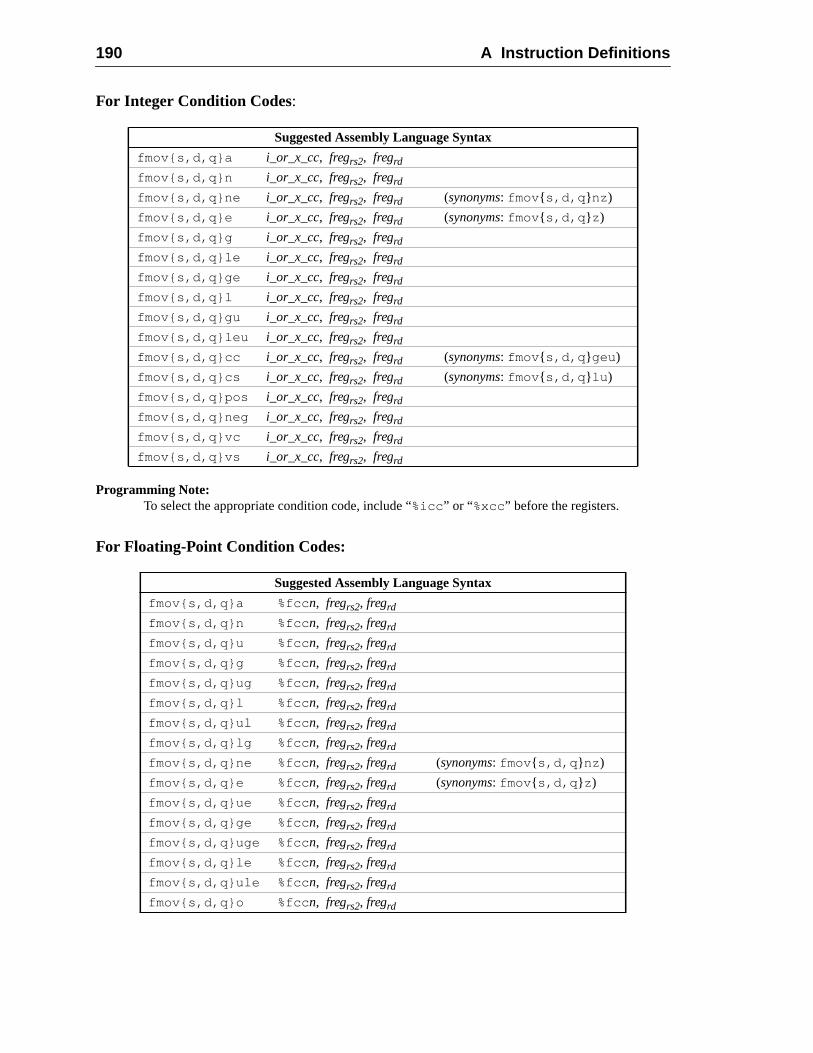
190 A Instruction Definitions
For Integer Condition Codes:
Programming Note:To select the appropriate condition code, include “%icc ” or “%xcc” before the registers.
For Floating-Point Condition Codes:
Suggested Assembly Language Syntax
fmov{s,d,q}a i_or_x_cc, fregrs2, fregrd
fmov{s,d,q}n i_or_x_cc, fregrs2, fregrd
fmov{s,d,q}ne i_or_x_cc, fregrs2, fregrd (synonyms: fmov { s,d,q } nz )
fmov{s,d,q}e i_or_x_cc, fregrs2, fregrd (synonyms: fmov { s,d,q } z )
fmov{s,d,q}g i_or_x_cc, fregrs2, fregrd
fmov{s,d,q}le i_or_x_cc, fregrs2, fregrd
fmov{s,d,q}ge i_or_x_cc, fregrs2, fregrd
fmov{s,d,q}l i_or_x_cc, fregrs2, fregrd
fmov{s,d,q}gu i_or_x_cc, fregrs2, fregrd
fmov{s,d,q}leu i_or_x_cc, fregrs2, fregrd
fmov{s,d,q}cc i_or_x_cc, fregrs2, fregrd (synonyms: fmov { s,d,q } geu )
fmov{s,d,q}cs i_or_x_cc, fregrs2, fregrd (synonyms: fmov { s,d,q } lu )
fmov{s,d,q}pos i_or_x_cc, fregrs2, fregrd
fmov{s,d,q}neg i_or_x_cc, fregrs2, fregrd
fmov{s,d,q}vc i_or_x_cc, fregrs2, fregrd
fmov{s,d,q}vs i_or_x_cc, fregrs2, fregrd
Suggested Assembly Language Syntax
fmov{s,d,q}a %fcc n, fregrs2, fregrd
fmov{s,d,q}n %fcc n, fregrs2, fregrd
fmov{s,d,q}u %fcc n, fregrs2, fregrd
fmov{s,d,q}g %fcc n, fregrs2, fregrd
fmov{s,d,q}ug %fcc n, fregrs2, fregrd
fmov{s,d,q}l %fcc n, fregrs2, fregrd
fmov{s,d,q}ul %fcc n, fregrs2, fregrd
fmov{s,d,q}lg %fcc n, fregrs2, fregrd
fmov{s,d,q}ne %fcc n, fregrs2, fregrd (synonyms: fmov { s,d,q } nz )
fmov{s,d,q}e %fcc n, fregrs2, fregrd (synonyms: fmov { s,d,q } z )
fmov{s,d,q}ue %fcc n, fregrs2, fregrd
fmov{s,d,q}ge %fcc n, fregrs2, fregrd
fmov{s,d,q}uge %fcc n, fregrs2, fregrd
fmov{s,d,q}le %fcc n, fregrs2, fregrd
fmov{s,d,q}ule %fcc n, fregrs2, fregrd
fmov{s,d,q}o %fcc n, fregrs2, fregrd
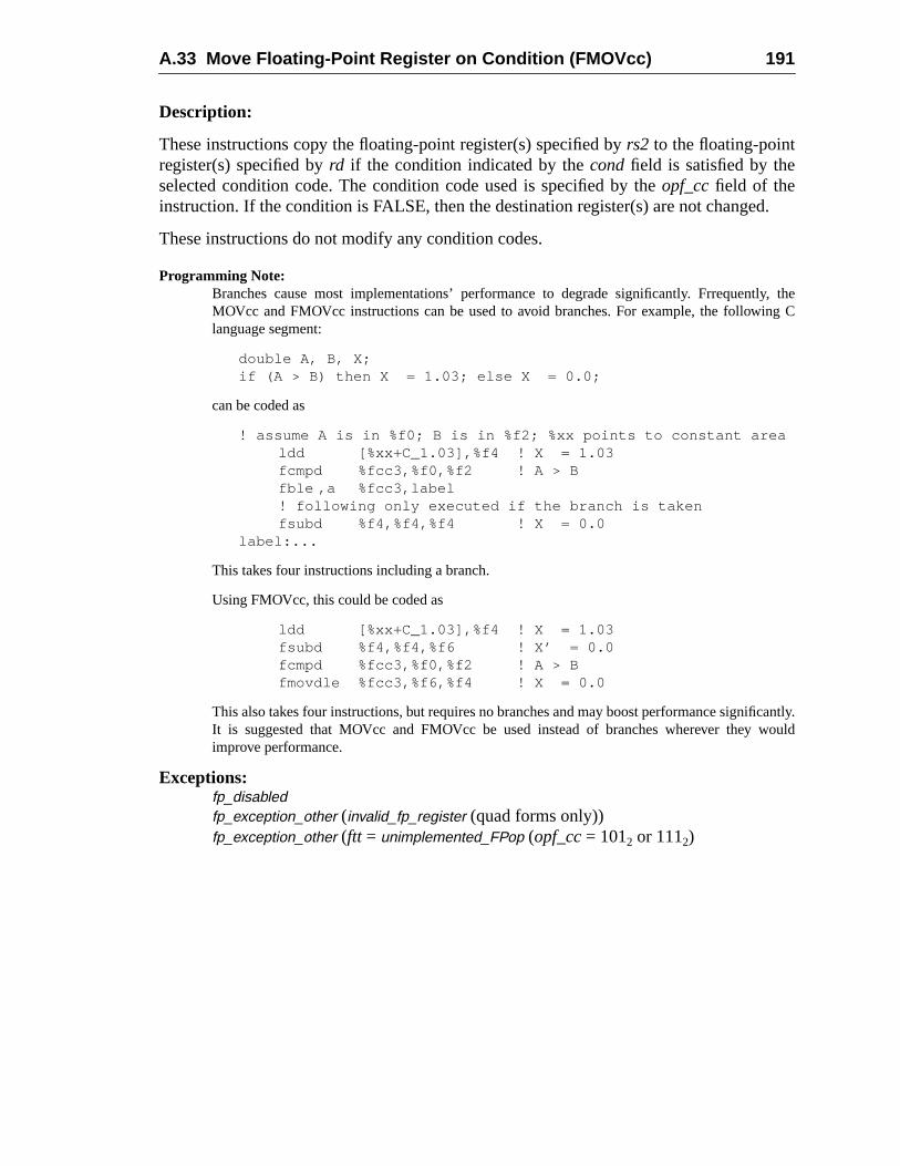
A.33 Move Floating-Point Register on Condition (FMOVcc) 191
d.
y, theg C
cantly.ould
Description:
These instructions copy the floating-point register(s) specified byrs2 to the floating-pointregister(s) specified byrd if the condition indicated by thecondfield is satisfied by theselected condition code. The condition code used is specified by theopf_ccfield of theinstruction. If the condition is FALSE, then the destination register(s) are not change
These instructions do not modify any condition codes.
Programming Note:Branches cause most implementations’ performance to degrade significantly. FrrequentlMOVcc and FMOVcc instructions can be used to avoid branches. For example, the followinlanguage segment:
double A, B, X;if (A > B) then X = 1.03; else X = 0.0;
can be coded as
! assume A is in %f0; B is in %f2; %xx points to constant arealdd [%xx+C_1.03],%f4 ! X = 1.03fcmpd %fcc3,%f0,%f2 ! A > Bfble ,a %fcc3,label! following only executed if the branch is takenfsubd %f4,%f4,%f4 ! X = 0.0
label:...
This takes four instructions including a branch.
Using FMOVcc, this could be coded as
ldd [%xx+C_1.03],%f4 ! X = 1.03fsubd %f4,%f4,%f6 ! X’ = 0.0fcmpd %fcc3,%f0,%f2 ! A > Bfmovdle %fcc3,%f6,%f4 ! X = 0.0
This also takes four instructions, but requires no branches and may boost performance signifiIt is suggested that MOVcc and FMOVcc be used instead of branches wherever they wimprove performance.
Exceptions:fp_disabledfp_exception_other (invalid_fp_register (quad forms only))fp_exception_other (ftt = unimplemented_FPop (opf_cc= 1012 or 1112)
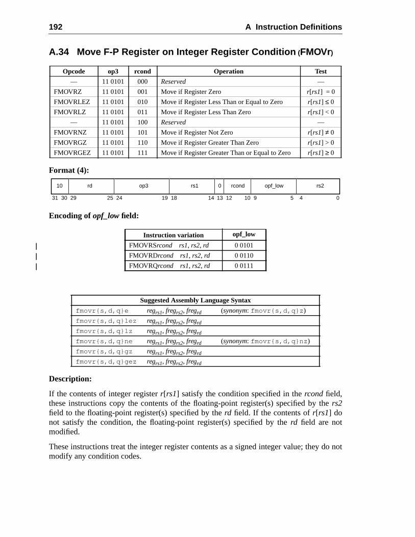
192 A Instruction Definitions
e
do not
A.34 Move F-P Register on Integer Register Condition (FMOVr)
Format (4):
Encoding ofopf_low field:
Description:
If the contents of integer registerr[rs1] satisfy the condition specified in thercond field,these instructions copy the contents of the floating-point register(s) specified by thrs2field to the floating-point register(s) specified by therd field. If the contents ofr[rs1] donot satisfy the condition, the floating-point register(s) specified by therd field are notmodified.
These instructions treat the integer register contents as a signed integer value; theymodify any condition codes.
Opcode op3 rcond Operation Test
— 11 0101 000 Reserved —
FMOVRZ 11 0101 001 Move if Register Zero r[rs1] = 0
FMOVRLEZ 11 0101 010 Move if Register Less Than or Equal to Zero r[rs1] ≤ 0
FMOVRLZ 11 0101 011 Move if Register Less Than Zero r[rs1] < 0
— 11 0101 100 Reserved —
FMOVRNZ 11 0101 101 Move if Register Not Zero r[rs1] ≠ 0
FMOVRGZ 11 0101 110 Move if Register Greater Than Zero r[rs1] > 0
FMOVRGEZ 11 0101 111 Move if Register Greater Than or Equal to Zero r[rs1] ≥ 0
Instruction variation opf_low
FMOVRSrcond rs1, rs2, rd 0 0101
FMOVRDrcond rs1, rs2, rd 0 0110
FMOVRQrcond rs1, rs2, rd 0 0111
Suggested Assembly Language Syntax
fmovr{s,d,q}e regrs1, fregrs2, fregrd (synonym: fmovr{s,d,q}z )
fmovr{s,d,q}lez regrs1, fregrs2, fregrd
fmovr{s,d,q}lz regrs1, fregrs2, fregrd
fmovr{s,d,q}ne regrs1, fregrs2, fregrd (synonym: fmovr{s,d,q}nz )
fmovr{s,d,q}gz regrs1, fregrs2, fregrd
fmovr{s,d,q}gez regrs1, fregrs2, fregrd
31 141924 18 13 12 9 5 4 0102530 29
10 rd op3 0 rcond opf_low rs2rs1
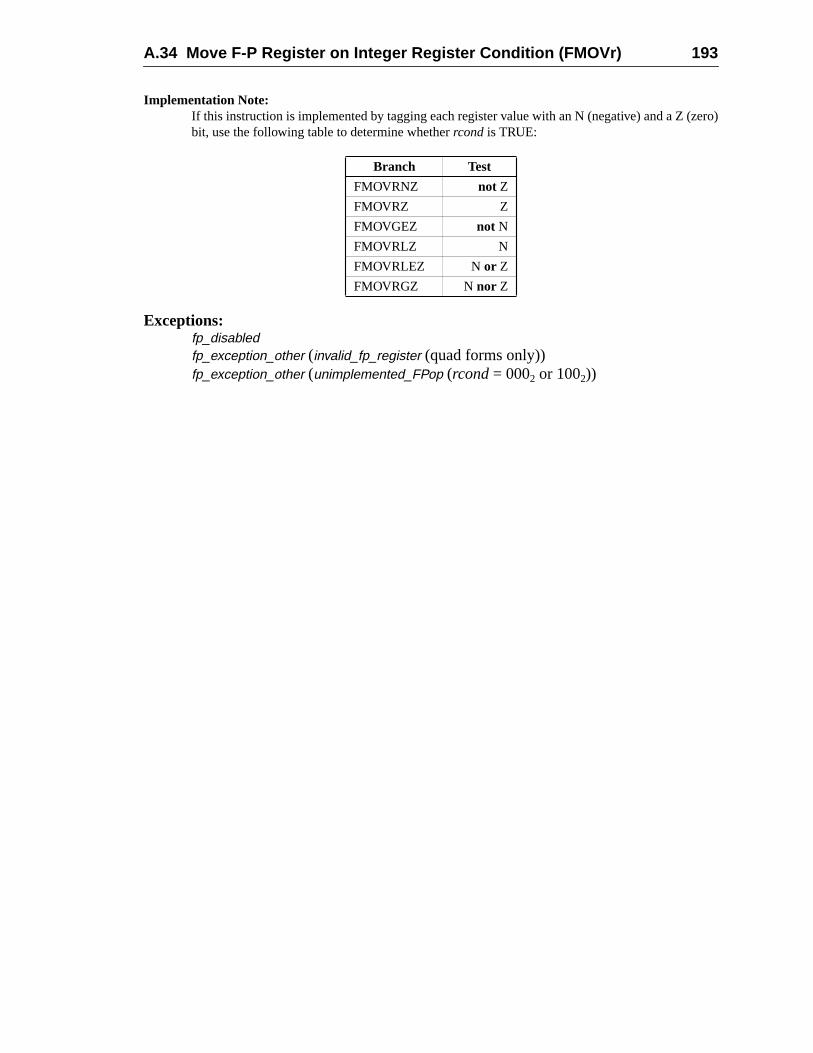
A.34 Move F-P Register on Integer Register Condition (FMOVr) 193
zero)
Implementation Note:If this instruction is implemented by tagging each register value with an N (negative) and a Z (bit, use the following table to determine whetherrcond is TRUE:
Exceptions:fp_disabledfp_exception_other (invalid_fp_register (quad forms only))fp_exception_other (unimplemented_FPop (rcond= 0002 or 1002))
Branch Test
FMOVRNZ not Z
FMOVRZ Z
FMOVGEZ not N
FMOVRLZ N
FMOVRLEZ N or Z
FMOVRGZ N nor Z
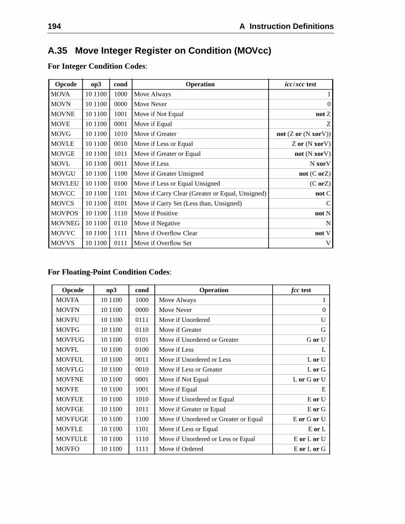
194 A Instruction Definitions
C
A.35 Move Integer Register on Condition (MOVcc)
For Integer Condition Codes:
For Floating-Point Condition Codes:
Opcode op3 cond Operation icc/xcc test
MOVA 10 1100 1000 Move Always 1
MOVN 10 1100 0000 Move Never 0
MOVNE 10 1100 1001 Move if Not Equal not Z
MOVE 10 1100 0001 Move if Equal Z
MOVG 10 1100 1010 Move if Greater not (Z or (N xorV))
MOVLE 10 1100 0010 Move if Less or Equal Z or (N xorV)
MOVGE 10 1100 1011 Move if Greater or Equal not (N xorV)
MOVL 10 1100 0011 Move if Less N xorV
MOVGU 10 1100 1100 Move if Greater Unsigned not (C orZ)
MOVLEU 10 1100 0100 Move if Less or Equal Unsigned (C orZ)
MOVCC 10 1100 1101 Move if Carry Clear (Greater or Equal, Unsigned) not C
MOVCS 10 1100 0101 Move if Carry Set (Less than, Unsigned)
MOVPOS 10 1100 1110 Move if Positive not N
MOVNEG 10 1100 0110 Move if Negative N
MOVVC 10 1100 1111 Move if Overflow Clear not V
MOVVS 10 1100 0111 Move if Overflow Set V
Opcode op3 cond Operation fcc test
MOVFA 10 1100 1000 Move Always 1
MOVFN 10 1100 0000 Move Never 0
MOVFU 10 1100 0111 Move if Unordered U
MOVFG 10 1100 0110 Move if Greater G
MOVFUG 10 1100 0101 Move if Unordered or Greater Gor U
MOVFL 10 1100 0100 Move if Less L
MOVFUL 10 1100 0011 Move if Unordered or Less Lor U
MOVFLG 10 1100 0010 Move if Less or Greater Lor G
MOVFNE 10 1100 0001 Move if Not Equal Lor G or U
MOVFE 10 1100 1001 Move if Equal E
MOVFUE 10 1100 1010 Move if Unordered or Equal Eor U
MOVFGE 10 1100 1011 Move if Greater or Equal Eor G
MOVFUGE 10 1100 1100 Move if Unordered or Greater or Equal Eor G or U
MOVFLE 10 1100 1101 Move if Less or Equal Eor L
MOVFULE 10 1100 1110 Move if Unordered or Less or Equal Eor L or U
MOVFO 10 1100 1111 Move if Ordered Eor L or G
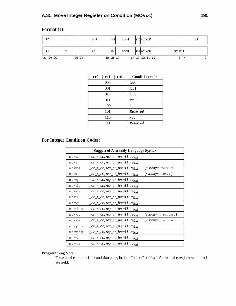
A.35 Move Integer Register on Condition (MOVcc) 195
Format (4):
For Integer Condition Codes:
Programming Note:To select the appropriate condition code, include “%icc ” or “ %xcc” before the register or immedi-ate field.
cc2 cc1 cc0 Condition code
000 fcc0
001 fcc1
010 fcc2
011 fcc3
100 icc
101 Reserved
110 xcc
111 Reserved
Suggested Assembly Language Syntax
mova i_or_x_cc, reg_or_imm11, regrd
movn i_or_x_cc, reg_or_imm11, regrd
movne i_or_x_cc, reg_or_imm11, regrd (synonym: movnz)
move i_or_x_cc, reg_or_imm11, regrd (synonym: movz)
movg i_or_x_cc, reg_or_imm11, regrd
movle i_or_x_cc, reg_or_imm11, regrd
movge i_or_x_cc, reg_or_imm11, regrd
movl i_or_x_cc, reg_or_imm11, regrd
movgu i_or_x_cc, reg_or_imm11, regrd
movleu i_or_x_cc, reg_or_imm11, regrd
movcc i_or_x_cc, reg_or_imm11, regrd (synonym: movgeu)movcs i_or_x_cc, reg_or_imm11, regrd (synonym: movlu )
movpos i_or_x_cc, reg_or_imm11, regrd
movneg i_or_x_cc, reg_or_imm11, regrd
movvc i_or_x_cc, reg_or_imm11, regrd
movvs i_or_x_cc, reg_or_imm11, regrd
31 24 02530 29 19 18
rd10 op3 —
14 13 12 5 4
cond rs2i=0
rd10 op3 cond simm11i=1
17
cc2
cc2
11
cc1
cc1
10
cc0
cc0
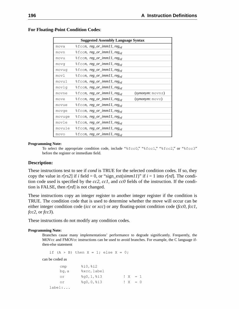
196 A Instruction Definitions
y
on isn be
y, thege if-
For Floating-Point Condition Codes:
Programming Note:To select the appropriate condition code, include “%fcc0 ,” “ %fcc1 ,” “ %fcc2 ,” or “%fcc3 ”before the register or immediate field.
Description:
These instructions test to see ifcondis TRUE for the selected condition codes. If so, thecopy the value inr[rs2] if i field = 0, or “sign_ext(simm11)” if i = 1 into r[rd]. The condi-tion code used is specified by thecc2, cc1, andcc0fields of the instruction. If the condi-tion is FALSE, thenr[rd] is not changed.
These instructions copy an integer register to another integer register if the conditiTRUE. The condition code that is used to determine whether the move will occur caeither integer condition code (icc or xcc) or any floating-point condition code (fcc0, fcc1,fcc2, or fcc3).
These instructions do not modify any condition codes.
Programming Note:Branches cause many implementations’ performance to degrade significantly. FrequentlMOVcc and FMOVcc instructions can be used to avoid branches. For example, the C languathen-else statement
if (A > B) then X = 1; else X = 0;
can be coded as
cmp %i0,%i2bg,a %xcc,label
or %g0,1,%i3 ! X = 1
or %g0,0,%i3 ! X = 0
label:...
Suggested Assembly Language Syntax
mova %fcc n, reg_or_imm11, regrd
movn %fcc n, reg_or_imm11, regrd
movu %fcc n, reg_or_imm11, regrd
movg %fcc n, reg_or_imm11, regrd
movug %fcc n, reg_or_imm11, regrd
movl %fcc n, reg_or_imm11, regrd
movul %fcc n, reg_or_imm11, regrd
movlg %fcc n, reg_or_imm11, regrd
movne %fcc n, reg_or_imm11, regrd (synonym: movnz)
move %fcc n, reg_or_imm11, regrd (synonym: movz)
movue %fcc n, reg_or_imm11, regrd
movge %fcc n, reg_or_imm11, regrd
movuge %fcc n, reg_or_imm11, regrd
movle %fcc n, reg_or_imm11, regrd
movule %fcc n, reg_or_imm11, regrd
movo %fcc n, reg_or_imm11, regrd
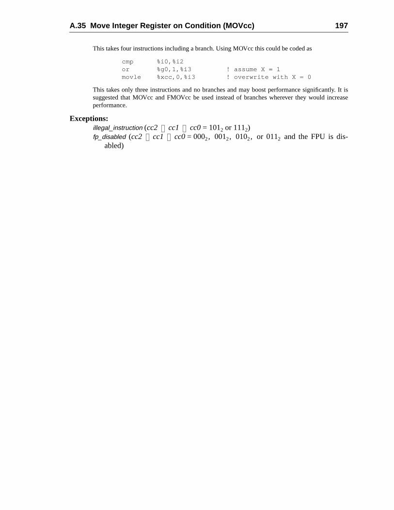
A.35 Move Integer Register on Condition (MOVcc) 197
y. It isrease
This takes four instructions including a branch. Using MOVcc this could be coded as
cmp %i0,%i2or %g0,1,%i3 ! assume X = 1movle %xcc,0,%i3 ! overwrite with X = 0
This takes only three instructions and no branches and may boost performance significantlsuggested that MOVcc and FMOVcc be used instead of branches wherever they would incperformance.
Exceptions:illegal_instruction (cc2 cc1 cc0= 1012 or 1112)fp_disabled (cc2 cc1 cc0= 0002, 0012, 0102, or 0112 and the FPU is dis-
abled)
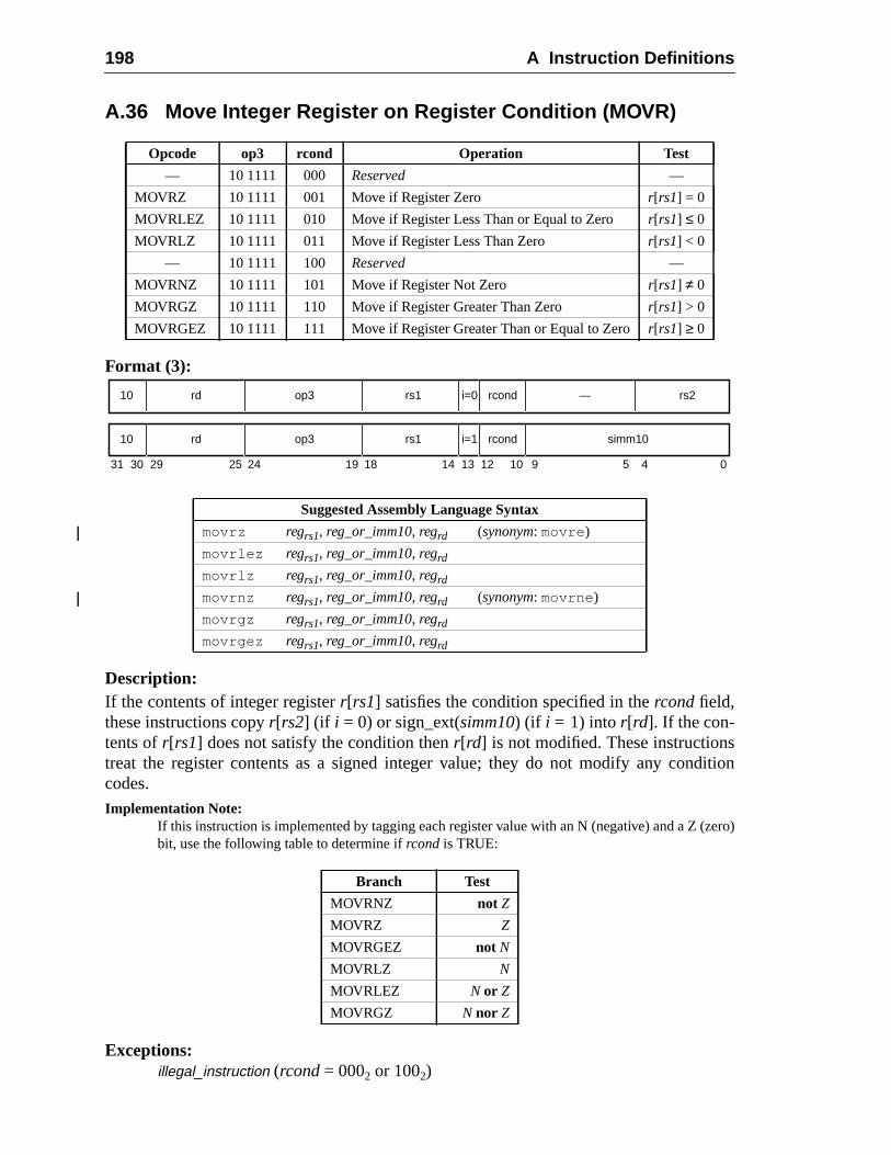
198 A Instruction Definitions
dition
zero)
A.36 Move Integer Register on Register Condition (MOVR)
Format (3):
Description:If the contents of integer registerr[rs1] satisfies the condition specified in thercondfield,these instructions copyr[rs2] (if i = 0) or sign_ext(simm10) (if i = 1) into r[rd]. If the con-tents ofr[rs1] does not satisfy the condition thenr[rd] is not modified. These instructionstreat the register contents as a signed integer value; they do not modify any concodes.Implementation Note:
If this instruction is implemented by tagging each register value with an N (negative) and a Z (bit, use the following table to determine ifrcond is TRUE:
Exceptions:illegal_instruction (rcond= 0002 or 1002)
Opcode op3 rcond Operation Test
— 10 1111 000 Reserved —
MOVRZ 10 1111 001 Move if Register Zero r[rs1] = 0
MOVRLEZ 10 1111 010 Move if Register Less Than or Equal to Zero r[rs1] ≤ 0
MOVRLZ 10 1111 011 Move if Register Less Than Zero r[rs1] < 0
— 10 1111 100 Reserved —
MOVRNZ 10 1111 101 Move if Register Not Zero r[rs1] ≠ 0
MOVRGZ 10 1111 110 Move if Register Greater Than Zero r[rs1] > 0
MOVRGEZ 10 1111 111 Move if Register Greater Than or Equal to Zeror[rs1] ≥ 0
Suggested Assembly Language Syntax
movrz regrs1, reg_or_imm10, regrd (synonym: movre )
movrlez regrs1, reg_or_imm10, regrd
movrlz regrs1, reg_or_imm10, regrd
movrnz regrs1, reg_or_imm10, regrd (synonym: movrne )
movrgz regrs1, reg_or_imm10, regrd
movrgez regrs1, reg_or_imm10, regrd
Branch Test
MOVRNZ not Z
MOVRZ Z
MOVRGEZ not N
MOVRLZ N
MOVRLEZ N or Z
MOVRGZ N nor Z
31 24 02530 29 19 18
rd10 op3 —
14 13 12 5 4
rs1 rs2i=0
rd10 op3 rs1 simm10i=1
rcond
rcond
10 9
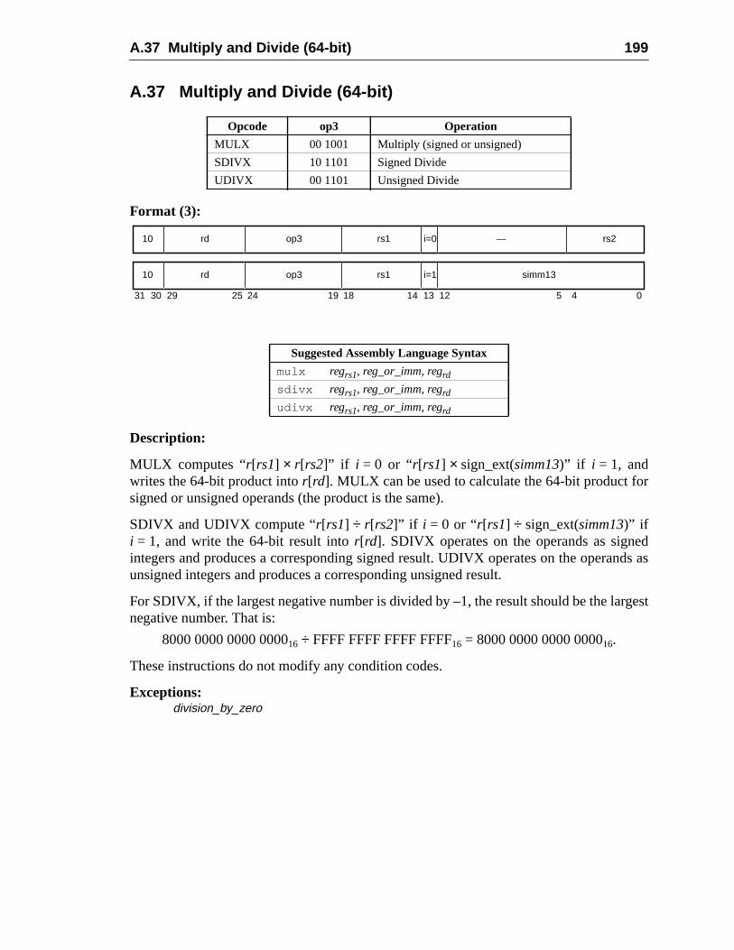
A.37 Multiply and Divide (64-bit) 199
r
ednds as
rgest
A.37 Multiply and Divide (64-bit)
Format (3):
Description:
MULX computes “r[rs1] × r[rs2]” if i = 0 or “r[rs1] × sign_ext(simm13)” if i = 1, andwrites the 64-bit product intor[rd]. MULX can be used to calculate the 64-bit product fosigned or unsigned operands (the product is the same).
SDIVX and UDIVX compute “r[rs1] ÷ r[rs2]” if i = 0 or “r[rs1] ÷ sign_ext(simm13)” ifi = 1, and write the 64-bit result intor[rd]. SDIVX operates on the operands as signintegers and produces a corresponding signed result. UDIVX operates on the operaunsigned integers and produces a corresponding unsigned result.
For SDIVX, if the largest negative number is divided by –1, the result should be the lanegative number. That is:
8000 0000 0000 000016 ÷ FFFF FFFF FFFF FFFF16 = 8000 0000 0000 000016.
These instructions do not modify any condition codes.
Exceptions:division_by_zero
Opcode op3 Operation
MULX 00 1001 Multiply (signed or unsigned)
SDIVX 10 1101 Signed Divide
UDIVX 00 1101 Unsigned Divide
Suggested Assembly Language Syntax
mulx regrs1, reg_or_imm, regrdsdivx regrs1, reg_or_imm, regrdudivx regrs1, reg_or_imm, regrd
31 24 02530 29 19 18
rd10 op3 —
14 13 12 5 4
rs1 rs2i=0
rd10 op3 rs1 simm13i=1
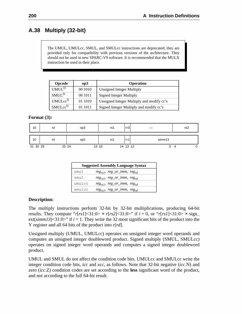
200 A Instruction Definitions
bit
he
andcc)
leword
he
A.38 Multiply (32-bit)
Format (3):
Description:
The multiply instructions perform 32-bit by 32-bit multiplications, producing 64-results. They compute “r[rs1]<31:0> × r[rs2]<31:0>” if i = 0, or “r[rs1]<31:0> × sign_ext(simm13)<31:0>” if i = 1. They write the 32 most significant bits of the product into tY register and all 64 bits of the product intor[rd].
Unsigned multiply (UMUL, UMULcc) operates on unsigned integer word operandscomputes an unsigned integer doubleword product. Signed multiply (SMUL, SMULoperates on signed integer word operands and computes a signed integer doubproduct.
UMUL and SMUL do not affect the condition code bits. UMULcc and SMULcc write tinteger condition code bits,icc andxcc, as follows. Note that 32-bit negative (icc.N) andzero (icc.Z) condition codes are set according to thelesssignificant word of the product,and not according to the full 64-bit result.
Opcode op3 Operation
UMULD 00 1010 Unsigned Integer Multiply
SMULD 00 1011 Signed Integer Multiply
UMULccD 01 1010 Unsigned Integer Multiply and modify cc’s
SMULccD 01 1011 Signed Integer Multiply and modify cc’s
Suggested Assembly Language Syntax
umul regrs1, reg_or_imm, regrd
smul regrs1, reg_or_imm, regrd
umulcc regrs1, reg_or_imm, regrd
smulcc regrs1, reg_or_imm, regrd
The UMUL, UMULcc, SMUL, and SMULcc instructions are deprecated; they areprovided only for compatibility with previous versions of the architecture. Theyshould not be used in new SPARC-V9 software. It is recommended that the MULXinstruction be used in their place.
31 24 02530 29 19 18
rd10 op3 —
14 13 12 5 4
rs1 rs2i=0
rd10 op3 rs1 simm13i=1
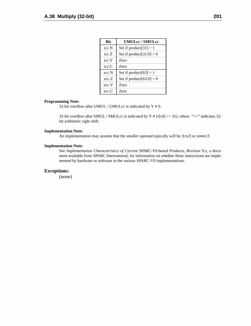
A.38 Multiply (32-bit) 201
ple-
Programming Note:32-bit overflow after UMUL / UMULcc is indicated by Y≠ 0.
32-bit overflow after SMUL / SMULcc is indicated by Y≠ (r[rd] >> 31), where “>>” indicates 32-bit arithmetic right shift.
Implementation Note:An implementation may assume that the smaller operand typically will ber[rs2] or simm13.
Implementation Note:SeeImplementation Characteristics of Current SPARC-V9-based Products, Revision 9.x, a docu-ment available from SPARC International, for information on whether these instructions are immented by hardware or software in the various SPARC-V9 implementations.
Exceptions:(none)
Bit UMULcc / SMULcc
icc.N Set if product[31] = 1
icc.Z Set if product[31:0] = 0
icc.V Zero
icc.C Zero
xcc.N Set if product[63] = 1
xcc.Z Set if product[63:0] = 0
xcc.V Zero
xcc.C Zero
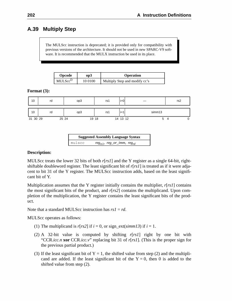
202 A Instruction Definitions
t-
nifi-
-rod-
li-the
A.39 Multiply Step
Format (3):
Description:
MULScc treats the lower 32 bits of bothr[rs1] and the Y register as a single 64-bit, righshiftable doubleword register. The least significant bit ofr[rs1] is treated as if it were adja-cent to bit 31 of the Y register. The MULScc instruction adds, based on the least sigcant bit of Y.
Multiplication assumes that the Y register initially contains the multiplier,r[rs1] containsthe most significant bits of the product, andr[rs2] contains the multiplicand. Upon completion of the multiplication, the Y register contains the least significant bits of the puct.
Note that a standard MULScc instruction hasrs1 = rd.
MULScc operates as follows:
(1) The multiplicand isr[rs2] if i = 0, or sign_ext(simm13) if i = 1.
(2) A 32-bit value is computed by shiftingr[rs1] right by one bit with“CCR.icc.nxor CCR.icc.v” replacing bit 31 ofr[rs1]. (This is the proper sign forthe previous partial product.)
(3) If the least significant bit of Y = 1, the shifted value from step (2) and the multipcand are added. If the least significant bit of the Y = 0, then 0 is added toshifted value from step (2).
Opcode op3 Operation
MULSccD 10 0100 Multiply Step and modify cc’s
Suggested Assembly Language Syntax
mulscc regrs1, reg_or_imm, regrd
The MULScc instruction is deprecated; it is provided only for compatibility withprevious versions of the architecture. It should not be used in new SPARC-V9 soft-ware. It is recommended that the MULX instruction be used in its place.
31 24 02530 29 19 18
rd10 op3 —
14 13 12 5 4
rs1 rs2i=0
rd10 op3 rs1 simm13i=1
A.39 Multiply Step 203
rmed
he
(4) The sum from step (3) is written intor[rd]. The upper 32-bits ofr[rd] are unde-fined. The integer condition codes are updated according to the addition perfoin step (3). The values of the extended condition codes are undefined.
(5) The Y register is shifted right by one bit, with the least significant bit of tunshiftedr[rs1] replacing bit 31of Y.
Exceptions:(none)
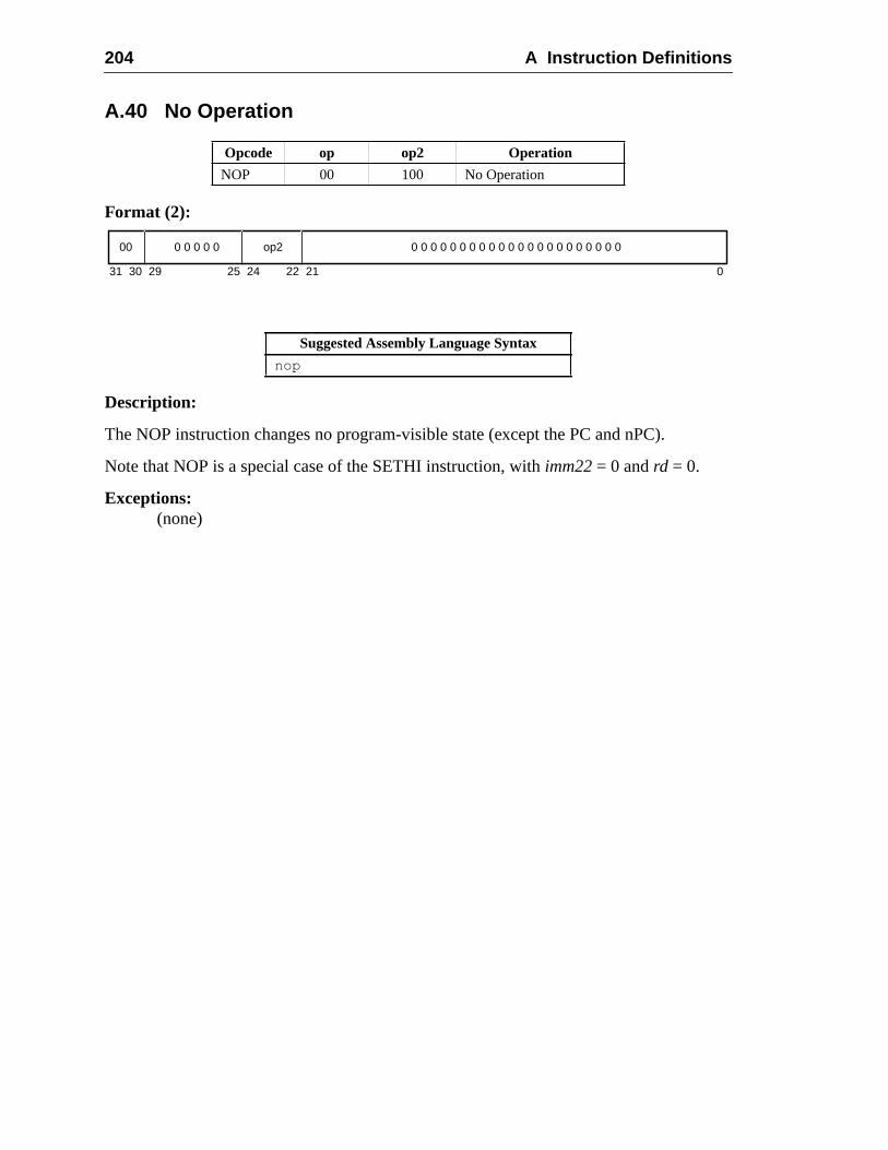
204 A Instruction Definitions
A.40 No Operation
Format (2):
Description:
The NOP instruction changes no program-visible state (except the PC and nPC).
Note that NOP is a special case of the SETHI instruction, withimm22= 0 andrd = 0.
Exceptions:(none)
Opcode op op2 Operation
NOP 00 100 No Operation
Suggested Assembly Language Syntax
nop
31 24 02530 29 22 21
00 op2 0 0 0 0 0 0 0 0 0 0 0 0 0 0 0 0 0 0 0 0 0 00 0 0 0 0
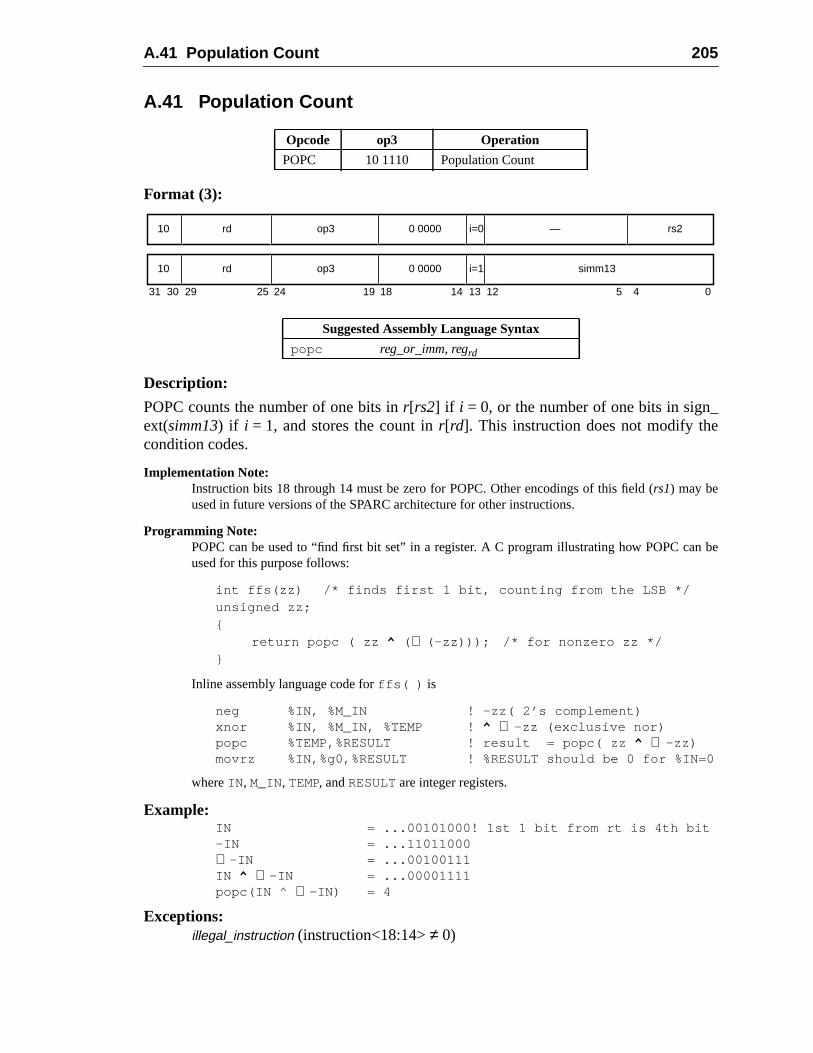
A.41 Population Count 205
A.41 Population Count
Format (3):
Description:
POPC counts the number of one bits inr[rs2] if i = 0, or the number of one bits in sign_ext(simm13) if i = 1, and stores the count inr[rd]. This instruction does not modify thecondition codes.
Implementation Note:Instruction bits 18 through 14 must be zero for POPC. Other encodings of this field (rs1) may beused in future versions of the SPARC architecture for other instructions.
Programming Note:POPC can be used to “find first bit set” in a register. A C program illustrating how POPC can beused for this purpose follows:
int ffs(zz) /* finds first 1 bit, counting from the LSB */unsigned zz;{
return popc ( zz ^ ( ∼ (–zz))); /* for nonzero zz */}
Inline assembly language code forffs( ) is
neg %IN, %M_IN ! –zz( 2’s complement)xnor %IN, %M_IN, %TEMP ! ^ ∼ –zz (exclusive nor)popc %TEMP,%RESULT ! result = popc( zz ^ ∼ –zz)movrz %IN,%g0,%RESULT ! %RESULT should be 0 for %IN=0
whereIN , M_IN, TEMP, andRESULT are integer registers.
Example:IN = ...00101000! 1st 1 bit from rt is 4th bit–IN = ...11011000∼ –IN = ...00100111IN ^ ∼ –IN = ...00001111popc(IN ^ ∼ –IN) = 4
Exceptions:illegal_instruction (instruction<18:14>≠ 0)
Opcode op3 Operation
POPC 10 1110 Population Count
Suggested Assembly Language Syntax
popc reg_or_imm, regrd
31 24 02530 29 19 18
rd10 op3 —
14 13 12 5 4
0 0000 rs2i=0
rd10 op3 0 0000 simm13i=1
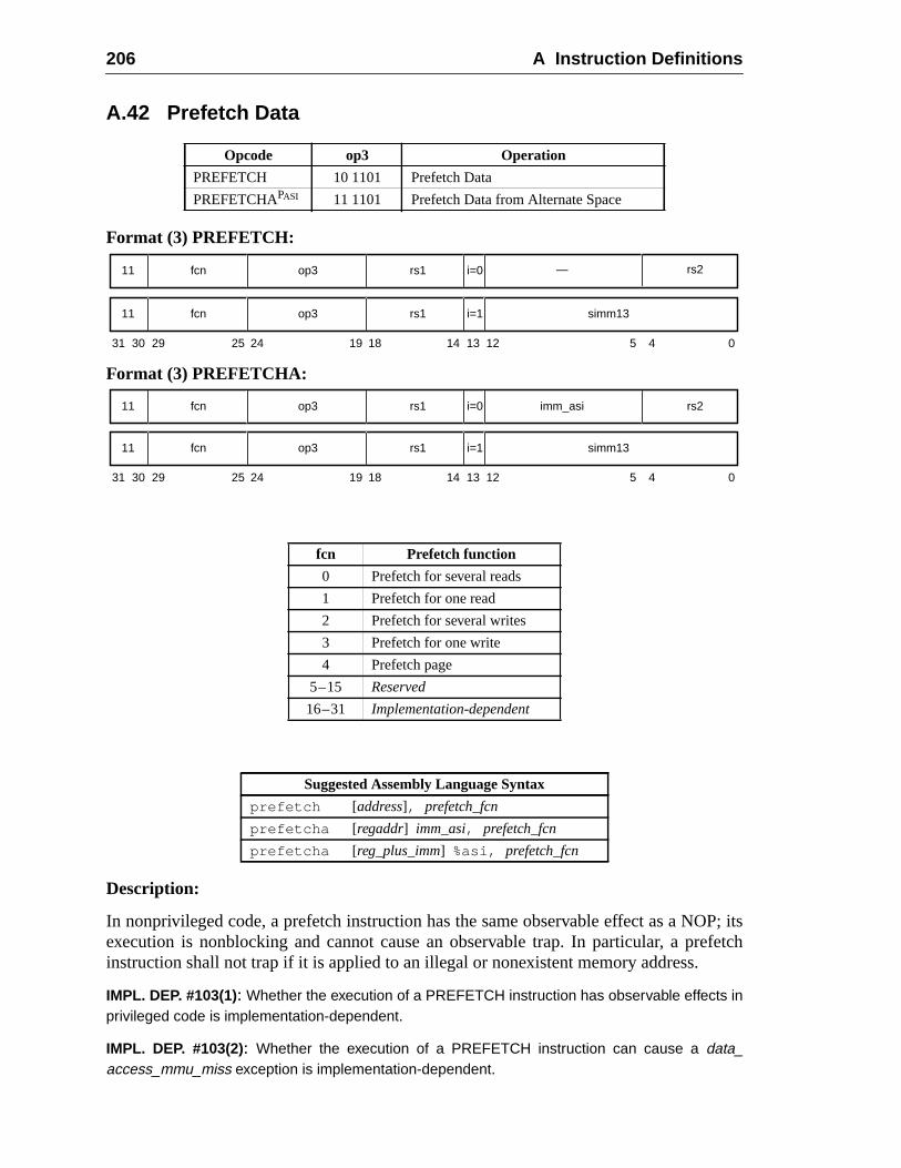
206 A Instruction Definitions
P; itsefetch
A.42 Prefetch Data
Format (3) PREFETCH:
Format (3) PREFETCHA:
Description:
In nonprivileged code, a prefetch instruction has the same observable effect as a NOexecution is nonblocking and cannot cause an observable trap. In particular, a prinstruction shall not trap if it is applied to an illegal or nonexistent memory address.
IMPL. DEP. #103(1): Whether the execution of a PREFETCH instruction has observable effects inprivileged code is implementation-dependent.
IMPL. DEP. #103(2): Whether the execution of a PREFETCH instruction can cause a data_access_mmu_miss exception is implementation-dependent.
Opcode op3 Operation
PREFETCH 10 1101 Prefetch Data
PREFETCHAPASI 11 1101 Prefetch Data from Alternate Space
fcn Prefetch function
0 Prefetch for several reads
1 Prefetch for one read
2 Prefetch for several writes
3 Prefetch for one write
4 Prefetch page
5–15 Reserved
16–31 Implementation-dependent
Suggested Assembly Language Syntax
prefetch [address], prefetch_fcn
prefetcha [regaddr] imm_asi, prefetch_fcn
prefetcha [reg_plus_imm] %asi, prefetch_fcn
31 24 02530 29 19 18 14 13 12 5 4
fcn11 op3 rs1 simm13i=1
fcn11 op3 rs1 i=0 — rs2
31 24 02530 29 19 18
fcn11 op3 imm_asi
14 13 12 5 4
rs1 rs2i=0
fcn11 op3 rs1 simm13i=1
A.42 Prefetch Data 207
-
pageld be
datas to the
byte
hables are
ary
load inntruc-
erent
Whether prefetch always succeeds when theMMU is disabled is implementation-dependent (impl. dep. # 117).
Implementation Note:Any effects of prefetch in privileged code should be reasonable (e.g., handling ECC errors, noprefetching allowed within code that handles page faults). The benefits of prefetching shouavailable to most privileged code.
Execution of a prefetch instruction initiates data movement (or preparation for futuremovement or address mapping) to reduce the latency of subsequent loads and storespecified address range.
A successful prefetch initiates movement of a block of data containing the addressedfrom memory toward the processor.
IMPL. DEP. #103(3): The size and alignment in memory of the data block is implementation-dependent; the minimum size is 64 bytes and the minimum alignment is a 64-byte boundary.
Programming Note:Software may prefetch 64 bytes beginning at an arbitrary addressaddressby issuing the instruc-tions
prefetch [ address], prefetch_fcn
prefetch [ address + 63], prefetch_fcn
Implementation Note:Prefetching may be used to help manage memory cache(s). A prefetch from a nonprefetclocation has no effect. It is up to memory management hardware to determine how locationidentified as not prefetchable.
Prefetch instructions that donot load from an alternate address space access the primaddress space (ASI_PRIMARY{_LITTLE}). Prefetch instructions thatdo load from analternate address space contain the address space identifier (ASI) to be used for thetheimm_asifield if i = 0, or in the ASI register ifi = 1. The access is privileged if bit seveof the ASI is zero; otherwise, it is not privileged. The effective address for these instions is “r[rs1] + r[rs2]” if i = 0, or “r[rs1] + sign_ext(simm13)” if i = 1.
Variants of the prefetch instruction can be used to prepare the memory system for difftypes of accesses.
IMPL. DEP. #103(4): An implementation may implement none, some, or all of these variants. Avariant not implemented shall execute as a nop. An implemented variant may support its fullsemantics, or may support just the simple common-case prefetching semantics.
IMPL. DEP. 103(6): Whether an attempt to reference a restricted ASI (< 8016) by a PREFETCHAinstruction while in nonprivileged mode (PSTATE.priv = 0) causes a privileged_action exception orexecutes as a NOP is implementation dependent.
A.42.1 Prefetch Variants
The prefetch variant is selected by thefcn field of the instruction.fcn values 5..15 arereserved for future extensions of the architecture.
208 A Instruction Definitions
his isificng as
s arers. Ifme ofd over-com-
e pro-
n the
en this
y theand not
ithout
ffect.
che
IMPL. DEP. #103(5): PREFETCH fcn values of 16..31 are implementation-dependent.
Each prefetch variant reflects an intent on the part of the compiler or programmer. Tdifferent from other instructions in SPARC-V9 (except BPN), all of which specify specactions. An implementation may implement a prefetch variant by any technique, as lothe intent of the variant is achieved.
The prefetch instruction is designed to treat the common cases well. The variantintended to provide scalability for future improvements in both hardware and compilea variant is implemented, then it should have the effects described below. In case sothe variants listed below are implemented and some are not, there is a recommendeloading of the unimplemented variants (see the Implementation Note labeled “Remended Overloadings” in A.42.2).
A.42.1.1 Prefetch for Several Reads ( fcn = 0)
The intent of this variant is to cause movement of data into the data cache nearest thcessor, with “reasonable” efforts made to obtain the data.
Implementation Note:If, for example, some TLB misses are handled in hardware, then they should be handled. Oother hand, a multiple ECC error is reasonable cause for cancellation of a prefetch.
This is the most important case of prefetching.
If the addressed data is already present (and owned, if necessary) in the cache, thvariant has no effect.
A.42.1.2 Prefetch for One Read ( fcn = 1)
This variant indicates that, if possible, the data cache should be minimally disturbed bdata read from the given address, because that data is expected to be read oncereused (read or written) soon after that.
If the data is already present in the cache, then this variant has no effect.
Programming Note:The intended use of this variant is in streaming large amounts of data into the processor woverwriting data in cache memory.
A.42.1.3 Prefetch for Several Writes (and Possibly Reads) ( fcn = 2)
The intent of this variant is to cause movement of data in preparation for writing.
If the addressed data is already present in the data cache, then this variant has no e
Programming Note:An example use of this variant is to write a dirty cache line back to memory, or to initialize a caline in preparation for a partial write.
A.42 Prefetch Data 209
eeded, line.
nt.
y theritten)
soft-ress,
cy of a
ariant
s andh had
d, the
ause
t any
ingA.7,
Implementation Note:On a multiprocessor, this variant indicates that exclusive ownership of the addressed data is nso it may have the additional effect of obtaining exclusive ownership of the addressed cache
Implementation Note:On a uniprocessor, there is no distinction between Prefetch for Several Reads and this varia
A.42.1.4 Prefetch for One Write ( fcn = 3)
This variant indicates that, if possible, the data cache should be minimally disturbed bdata written to this address, because that data is not expected to be reused (read or wsoon after it has been written once.
If the data is already present in the cache, then this variant has no effect.
A.42.1.5 Prefetch Page ( fcn = 4)
In a virtual-memory system, the intended action of this variant is for the supervisorware or hardware to initiate asynchronous mapping of the referenced virtual addassuming that it is legal to do so.
Programming Note:The desire is to avoid a later page fault for the given address, or at least to shorten the latenpage fault.
In a nonvirtual-memory system, or if the addressed page is already mapped, this vhas no effect.
The referenced page need not be mapped when the instruction completes. Loadstores issued before the page is mapped should block just as they would if the prefetcnever been issued. When the activity associated with the mapping has completeloads and stores may proceed.
Implementation Note:An example of mapping activity is DMA from secondary storage.
Implementation Note:Use of this variant may be disabled or restricted in privileged code that is not permitted to cpage faults.
A.42.1.6 Implementation-Dependent Prefetch ( fcn = 16..31)
These values are available for implementations to use. An implementation shall treaunimplemented prefetchfcn values as NOPs (impl. dep. #103).
A.42.2 General Comments
There is no variant of PREFETCH for instruction prefetching. Instruction prefetchshould be encoded using the Branch Never (BPN) form of the BPcc instruction (see“Branch on Integer Condition Codes with Prediction (BPcc)”).
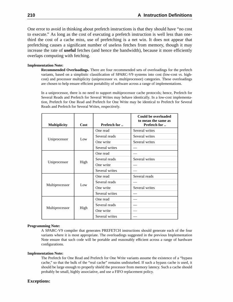
210 A Instruction Definitions
costone-r thatt mayntly
tch
gs.
tch forenta-veral
fourtation
rdware
ypasssed, itshould
One error to avoid in thinking about prefetch instructions is that they should have “noto execute.” As long as the cost of executing a prefetch instruction is well less thanthird the cost of a cache miss, use of prefetching is a net win. It does not appeaprefetching causes a significant number of useless fetches from memory, though iincrease the rate ofuseful fetches (and hence the bandwidth), because it more efficieoverlaps computing with fetching.
Implementation Note:Recommended Overloadings.There are four recommended sets of overloadings for the prefevariants, based on a simplistic classification of SPARC-V9 systems into cost (low-costvs. high-cost) and processor multiplicity (uniprocessorvs. multiprocessor) categories. These overloadinare chosen to help ensure efficient portability of software across a range of implementations
In a uniprocessor, there is no need to support multiprocessor cache protocols; hence, PrefeSeveral Reads and Prefetch for Several Writes may behave identically. In a low-cost implemtion, Prefetch for One Read and Prefetch for One Write may be identical to Prefetch for SeReads and Prefetch for Several Writes, respectively.
Programming Note:A SPARC-V9 compiler that generates PREFETCH instructions should generate each of thevariants where it is most appropriate. The overloadings suggested in the previous ImplemenNote ensure that such code will be portable and reasonably efficient across a range of haconfigurations.
Implementation Note:The Prefetch for One Read and Prefetch for One Write variants assume the existence of a “bcache,” so that the bulk of the “real cache” remains undisturbed. If such a bypass cache is ushould be large enough to properly shield the processor from memory latency. Such a cacheprobably be small, highly associative, and use a FIFO replacement policy.
Exceptions:
Multiplicity Cost Prefetch for ..
Could be overloadedto mean the same as
Prefetch for ..
Uniprocessor Low
One read Several writes
Several reads Several writes
One write Several writes
Several writes —
Uniprocessor High
One read —
Several reads Several writes
One write —
Several writes —
Multiprocessor Low
One read Several reads
Several reads —
One write Several writes
Several writes —
Multiprocessor High
One read —
Several reads —
One write —
Several writes —
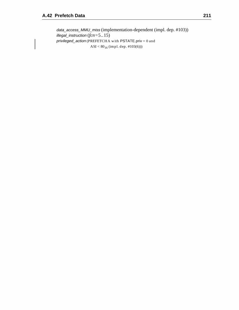
A.42 Prefetch Data 211
data_access_MMU_miss (implementation-dependent (impl. dep. #103))illegal_instruction (fcn=5..15)privileged_action (PREFETCHA with PSTATE.priv = 0 and
ASI < 8016 (impl. dep. #103(6)))
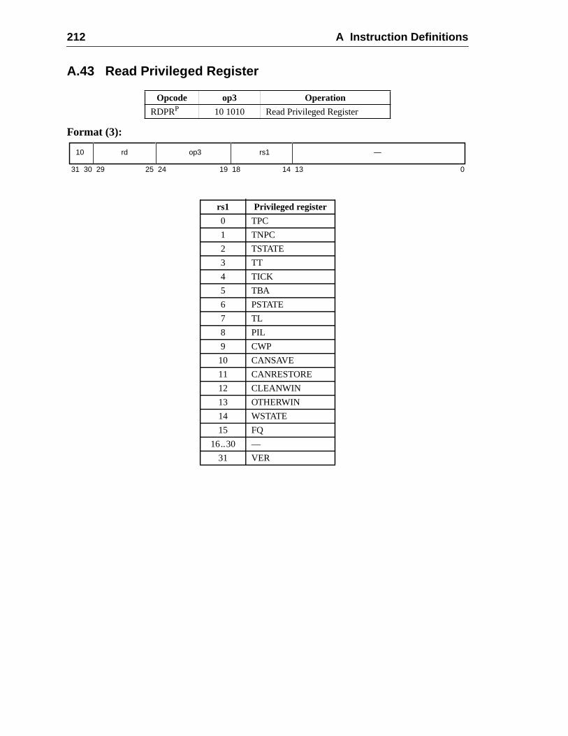
212 A Instruction Definitions
A.43 Read Privileged Register
Format (3):
Opcode op3 Operation
RDPRP 10 1010 Read Privileged Register
rs1 Privileged register
0 TPC
1 TNPC
2 TSTATE
3 TT
4 TICK
5 TBA
6 PSTATE
7 TL
8 PIL
9 CWP
10 CANSAVE
11 CANRESTORE
12 CLEANWIN
13 OTHERWIN
14 WSTATE
15 FQ
16..30 —
31 VER
31 141924 18 13 02530 29
10 rd op3 rs1 —
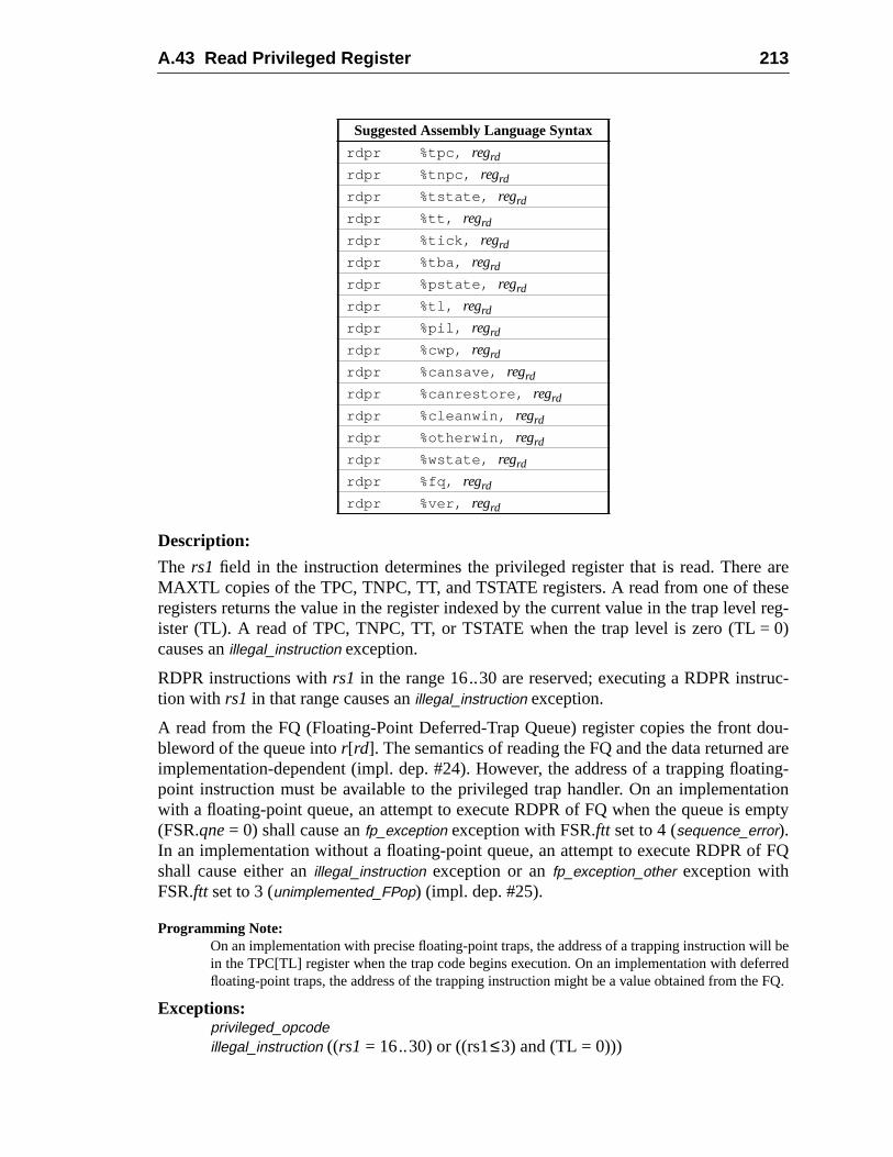
A.43 Read Privileged Register 213
areesel reg-0)
uc-
dou-areting-tionmpty
f FQ
ill beerrede FQ.
Description:
The rs1 field in the instruction determines the privileged register that is read. ThereMAXTL copies of the TPC, TNPC, TT, and TSTATE registers. A read from one of thregisters returns the value in the register indexed by the current value in the trap leveister (TL). A read of TPC, TNPC, TT, or TSTATE when the trap level is zero (TL =causes anillegal_instruction exception.
RDPR instructions withrs1 in the range 16..30 are reserved; executing a RDPR instrtion with rs1 in that range causes anillegal_instruction exception.
A read from the FQ (Floating-Point Deferred-Trap Queue) register copies the frontbleword of the queue intor[rd]. The semantics of reading the FQ and the data returnedimplementation-dependent (impl. dep. #24). However, the address of a trapping floapoint instruction must be available to the privileged trap handler. On an implementawith a floating-point queue, an attempt to execute RDPR of FQ when the queue is e(FSR.qne= 0) shall cause anfp_exception exception with FSR.ftt set to 4 (sequence_error).In an implementation without a floating-point queue, an attempt to execute RDPR oshall cause either anillegal_instruction exception or anfp_exception_other exception withFSR.ftt set to 3 (unimplemented_FPop) (impl. dep. #25).
Programming Note:On an implementation with precise floating-point traps, the address of a trapping instruction win the TPC[TL] register when the trap code begins execution. On an implementation with deffloating-point traps, the address of the trapping instruction might be a value obtained from th
Exceptions:privileged_opcodeillegal_instruction ((rs1 = 16..30) or ((rs1≤3) and (TL = 0)))
Suggested Assembly Language Syntax
rdpr %tpc, regrd
rdpr %tnpc, regrd
rdpr %tstate, regrd
rdpr %tt, regrd
rdpr %tick, regrd
rdpr %tba, regrd
rdpr %pstate, regrd
rdpr %tl, regrd
rdpr %pil, regrd
rdpr %cwp, regrd
rdpr %cansave, regrd
rdpr %canrestore, regrd
rdpr %cleanwin, regrd
rdpr %otherwin, regrd
rdpr %wstate, regrd
rdpr %fq, regrd
rdpr %ver, regrd
214 A Instruction Definitions
fp_exception_other (sequence_error) (RDPR of FQ when FSR.qne= 0 in a systemwith an FQ; (impl. dep. #25)
illegal_instruction (RDPR of FQ in a system without an FQ; (impl. dep. #25)
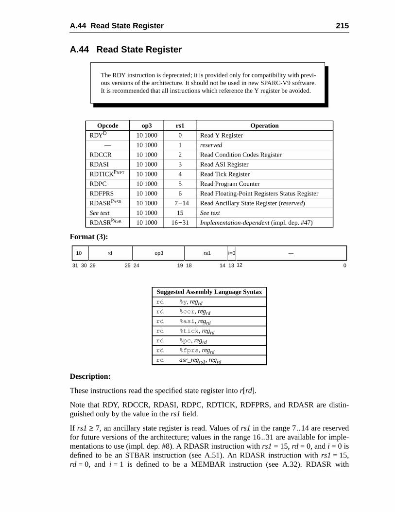
A.44 Read State Register 215
in-
dple-
th
A.44 Read State Register
Format (3):
Description:
These instructions read the specified state register intor[rd].
Note that RDY, RDCCR, RDASI, RDPC, RDTICK, RDFPRS, and RDASR are distguished only by the value in thers1 field.
If rs1 ≥ 7, an ancillary state register is read. Values ofrs1 in the range 7..14 are reservefor future versions of the architecture; values in the range 16..31 are available for immentations to use (impl. dep. #8). A RDASR instruction withrs1 = 15,rd = 0, andi = 0 isdefined to be an STBAR instruction (see A.51). An RDASR instruction withrs1 = 15,rd = 0, and i = 1 is defined to be a MEMBAR instruction (see A.32). RDASR wi
Opcode op3 rs1 Operation
RDYD 10 1000 0 Read Y Register
— 10 1000 1 reserved
RDCCR 10 1000 2 Read Condition Codes Register
RDASI 10 1000 3 Read ASI Register
RDTICKPNPT 10 1000 4 Read Tick Register
RDPC 10 1000 5 Read Program Counter
RDFPRS 10 1000 6 Read Floating-Point Registers Status Register
RDASRPASR 10 1000 7−14 Read Ancillary State Register (reserved)
See text 10 1000 15 See text
RDASRPASR 10 1000 16−31 Implementation-dependent (impl. dep. #47)
Suggested Assembly Language Syntax
rd %y, regrd
rd %ccr , regrd
rd %asi , regrd
rd %tick , regrd
rd %pc , regrd
rd %fprs , regrd
rd asr_regrs1, regrd
The RDY instruction is deprecated; it is provided only for compatibility with previ-ous versions of the architecture. It should not be used in new SPARC-V9 software.It is recommended that all instructions which reference the Y register be avoided.
31 141924 18 13 02530 29
10 rd op3 rs1 —
12
i=0
216 A Instruction Definitions
plete
ding
trap-evi-cil-
the
uc-
rs1 = 15 andrd≠0 is reserved for future versions of the architecture; it causes anillegal_instruction exception.
RDTICK causes aprivileged_action exception if PSTATE.PRIV = 0 and TICK.NPT = 1.
For RDPC, the high-order 32-bits of the PC value stored inr[rd] are implementation-dependent when PSTATE.AM = 1 (impl. dep. #125).
RDFPRS waits for all pending FPops and loads of floating-point registers to combefore reading the FPRS register.
IMPL. DEP. #47: RDASR instructions with rd in the range 16..31 are available for implementation-dependent uses (impl. dep. #8). For a RDASR instruction with rs1 in the range 16 .. 31, the follow-ing are implementation-dependent: the interpretation of bits 13:0 and 29:25 in the instruction,whether the instruction is privileged (impl. dep. #9), and whether the instruction causes an illegal_
instruction exception.
See I.1.1, “Read/Write Ancillary State Registers (ASRs),” for a discussion of extenthe SPARC-V9 instruction set using read/write ASR instructions.
Implementation Note:Ancillary state registers may include (for example) timer, counter, diagnostic, self-test, andcontrol registers. SeeImplementation Characteristics of Current SPARC-V9-based Products, Rsion 9.x, a document available from SPARC International, for information on implemented anlary state registers.
V8 Compatibility Note:The SPARC-V8 RDPSR, RDWIM, and RDTBR instructions do not exist in SPARC-V9 sincePSR, WIM, and TBR registers do not exist in SPARC-V9.
Exceptions:privileged_opcode (RDASR only; implementation-dependent (impl. dep. #47))illegal_instruction (RDASR with rs1 = 1 or 7..14; RDASR withrs1 = 15 andrd≠0;
RDASR withrs1 = 16..31 and the implementation does not define the instrtion as an extension; implementation-dependent (impl. dep. #47))
privileged_action (RDTICK only)
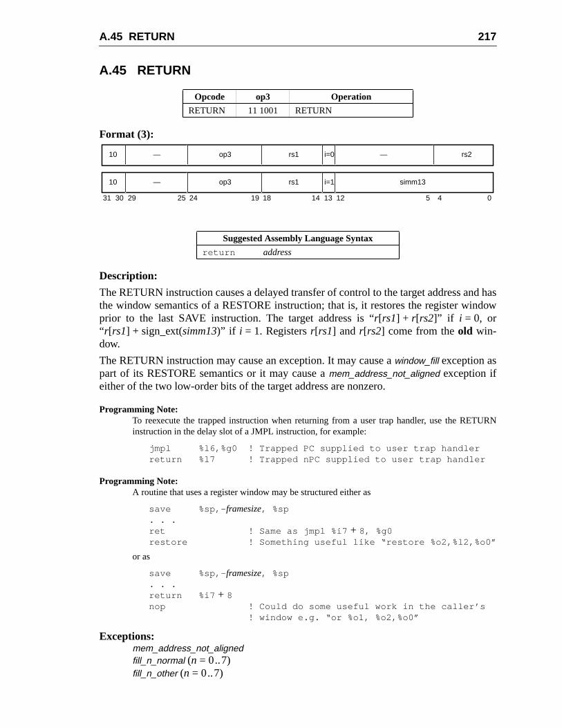
A.45 RETURN 217
nd hasdow
URN
A.45 RETURN
Format (3):
Description:
The RETURN instruction causes a delayed transfer of control to the target address athe window semantics of a RESTORE instruction; that is, it restores the register winprior to the last SAVE instruction. The target address is “r[rs1] + r[rs2]” if i = 0, or“ r[rs1] + sign_ext(simm13)” if i = 1. Registersr[rs1] and r[rs2] come from theold win-dow.
The RETURN instruction may cause an exception. It may cause awindow_fill exception aspart of its RESTORE semantics or it may cause amem_address_not_aligned exception ifeither of the two low-order bits of the target address are nonzero.
Programming Note:To reexecute the trapped instruction when returning from a user trap handler, use the RETinstruction in the delay slot of a JMPL instruction, for example:
jmpl %l6,%g0 ! Trapped PC supplied to user trap handlerreturn %l7 ! Trapped nPC supplied to user trap handler
Programming Note:A routine that uses a register window may be structured either as
save %sp,- framesize, %sp. . .ret ! Same as jmpl %i7 + 8, %g0restore ! Something useful like “restore %o2,%l2,%o0”
or as
save %sp,- framesize, %sp. . .return %i7 + 8nop ! Could do some useful work in the caller’s
! window e.g. “or %o1, %o2,%o0”
Exceptions:mem_address_not_alignedfill_n_normal (n = 0..7)fill_n_other (n = 0..7)
Opcode op3 Operation
RETURN 11 1001 RETURN
Suggested Assembly Language Syntax
return address
31 24 02530 29 19 18
—10 op3 —
14 13 12 5 4
rs1 rs2i=0
10 op3 rs1 simm13i=1—
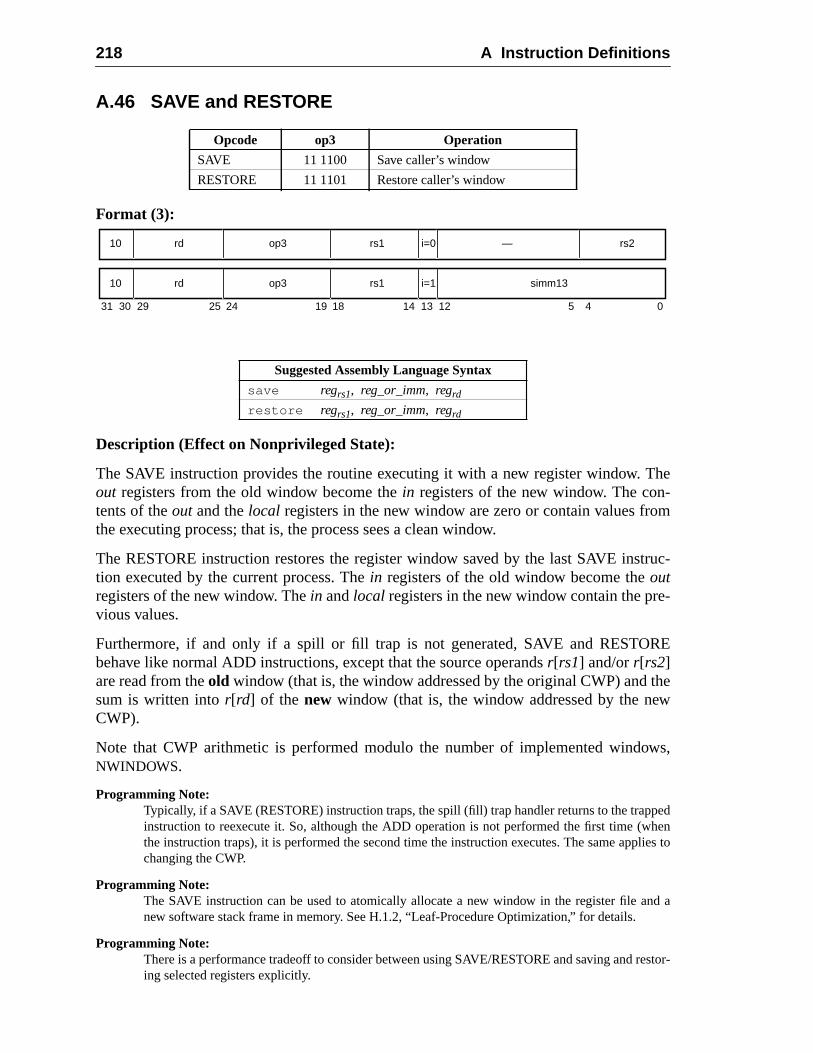
218 A Instruction Definitions
The-m
truc-
-
RE
thew
ws,
pedhenlies to
nd a
restor-
A.46 SAVE and RESTORE
Format (3):
Description (Effect on Nonprivileged State):
The SAVE instruction provides the routine executing it with a new register window.out registers from the old window become thein registers of the new window. The contents of theout and thelocal registers in the new window are zero or contain values frothe executing process; that is, the process sees a clean window.
The RESTORE instruction restores the register window saved by the last SAVE instion executed by the current process. Thein registers of the old window become theoutregisters of the new window. Thein andlocal registers in the new window contain the previous values.
Furthermore, if and only if a spill or fill trap is not generated, SAVE and RESTObehave like normal ADD instructions, except that the source operandsr[rs1] and/orr[rs2]are read from theold window (that is, the window addressed by the original CWP) andsum is written intor[rd] of the new window (that is, the window addressed by the neCWP).
Note that CWP arithmetic is performed modulo the number of implemented windoNWINDOWS.
Programming Note:Typically, if a SAVE (RESTORE) instruction traps, the spill (fill) trap handler returns to the trapinstruction to reexecute it. So, although the ADD operation is not performed the first time (wthe instruction traps), it is performed the second time the instruction executes. The same appchanging the CWP.
Programming Note:The SAVE instruction can be used to atomically allocate a new window in the register file anew software stack frame in memory. See H.1.2, “Leaf-Procedure Optimization,” for details.
Programming Note:There is a performance tradeoff to consider between using SAVE/RESTORE and saving anding selected registers explicitly.
Opcode op3 Operation
SAVE 11 1100 Save caller’s window
RESTORE 11 1101 Restore caller’s window
Suggested Assembly Language Syntax
save regrs1, reg_or_imm, regrd
restore regrs1, reg_or_imm, regrd
31 24 02530 29 19 18
rd10 op3 —
14 13 12 5 4
rs1 rs2i=0
10 op3 rs1 simm13i=1rd
A.46 SAVE and RESTORE 219
nting
ted.Thet is,
beat
d byenting
p isand
r is
andg the
a
Description (effect on privileged state):
If the SAVE instruction does not trap, it increments the CWP (mod NWINDOWS) to pro-vide a new register window and updates the state of the register windows by decremeCANSAVE and incrementing CANRESTORE.
If the new register window is occupied (that is, CANSAVE = 0), a spill trap is generaThe trap vector for the spill trap is based on the value of OTHERWIN and WSTATE.spill trap handler is invoked with the CWP set to point to the window to be spilled (thaold CWP+ 2).
If CANSAVE ≠ 0, the SAVE instruction checks whether the new window needs tocleaned. It causes aclean_window trap if the number of unused clean windows is zero, this, (CLEANWIN – CANRESTORE) = 0. Theclean_window trap handler is invoked withthe CWP set to point to the window to be cleaned (that is, old CWP+ 1).
If the RESTORE instruction does not trap, it decrements the CWP (mod NWINDOWS) torestore the register window that was in use prior to the last SAVE instruction executethe current process. It also updates the state of the register windows by decremCANRESTORE and incrementing CANSAVE.
If the register window to be restored has been spilled (CANRESTORE = 0), a fill tragenerated. The trap vector for the fill trap is based on the values of OTHERWINWSTATE, as described in 7.5.2.1, “Trap Type for Spill/Fill Traps.” The fill trap handleinvoked with CWP set to point to the window to be filled, that is, old CWP – 1.
Programming Note:The vectoring of spill and fill traps can be controlled by setting the value of the OTHERWINWSTATE registers appropriately. For details, see the unnumbered subsection titled “SplittinRegister Windows” in H.2.3, “Client-Server Model.”
Programming Note:The spill (fill) handler normally will end with a SAVED (RESTORED) instruction followed byRETRY instruction.
Exceptions:clean_window (SAVE only)fill_n_normal (RESTORE only,n=0..7)fill_n_other (RESTORE only,n = 0..7)spill_n_normal (SAVE only,n = 0..7)spill_n_other (SAVE only,n = 0..7)
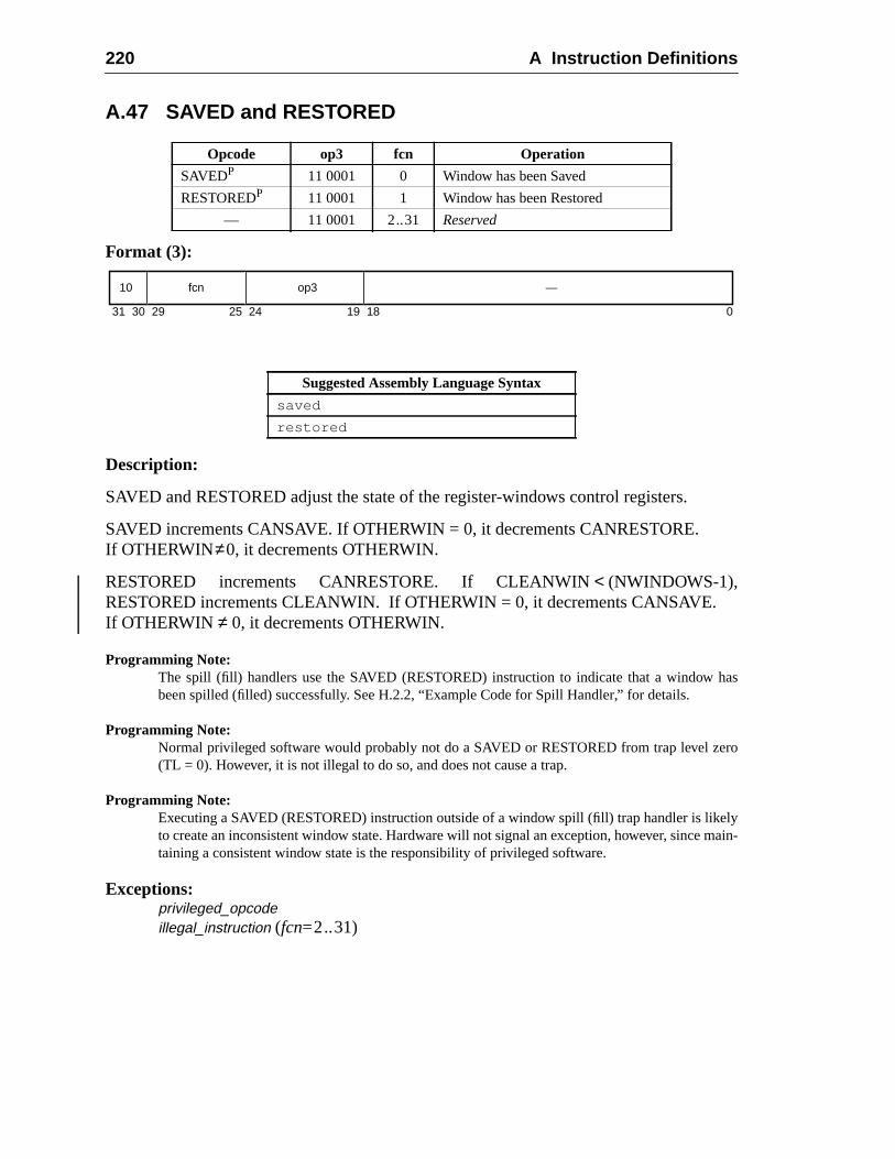
220 A Instruction Definitions
has
ero
lymain-
A.47 SAVED and RESTORED
Format (3):
Description:
SAVED and RESTORED adjust the state of the register-windows control registers.
SAVED increments CANSAVE. If OTHERWIN = 0, it decrements CANRESTORE.If OTHERWIN≠0, it decrements OTHERWIN.
RESTORED increments CANRESTORE. If CLEANWIN< (NWINDOWS-1),RESTORED increments CLEANWIN. If OTHERWIN = 0, it decrements CANSAVE.If OTHERWIN ≠ 0, it decrements OTHERWIN.
Programming Note:The spill (fill) handlers use the SAVED (RESTORED) instruction to indicate that a windowbeen spilled (filled) successfully. See H.2.2, “Example Code for Spill Handler,” for details.
Programming Note:Normal privileged software would probably not do a SAVED or RESTORED from trap level z(TL = 0). However, it is not illegal to do so, and does not cause a trap.
Programming Note:Executing a SAVED (RESTORED) instruction outside of a window spill (fill) trap handler is liketo create an inconsistent window state. Hardware will not signal an exception, however, sincetaining a consistent window state is the responsibility of privileged software.
Exceptions:privileged_opcodeillegal_instruction (fcn=2..31)
Opcode op3 fcn Operation
SAVEDP 11 0001 0 Window has been Saved
RESTOREDP 11 0001 1 Window has been Restored
— 11 0001 2..31 Reserved
Suggested Assembly Language Syntax
saved
restored
31 1924 18 02530 29
10 fcn op3 —
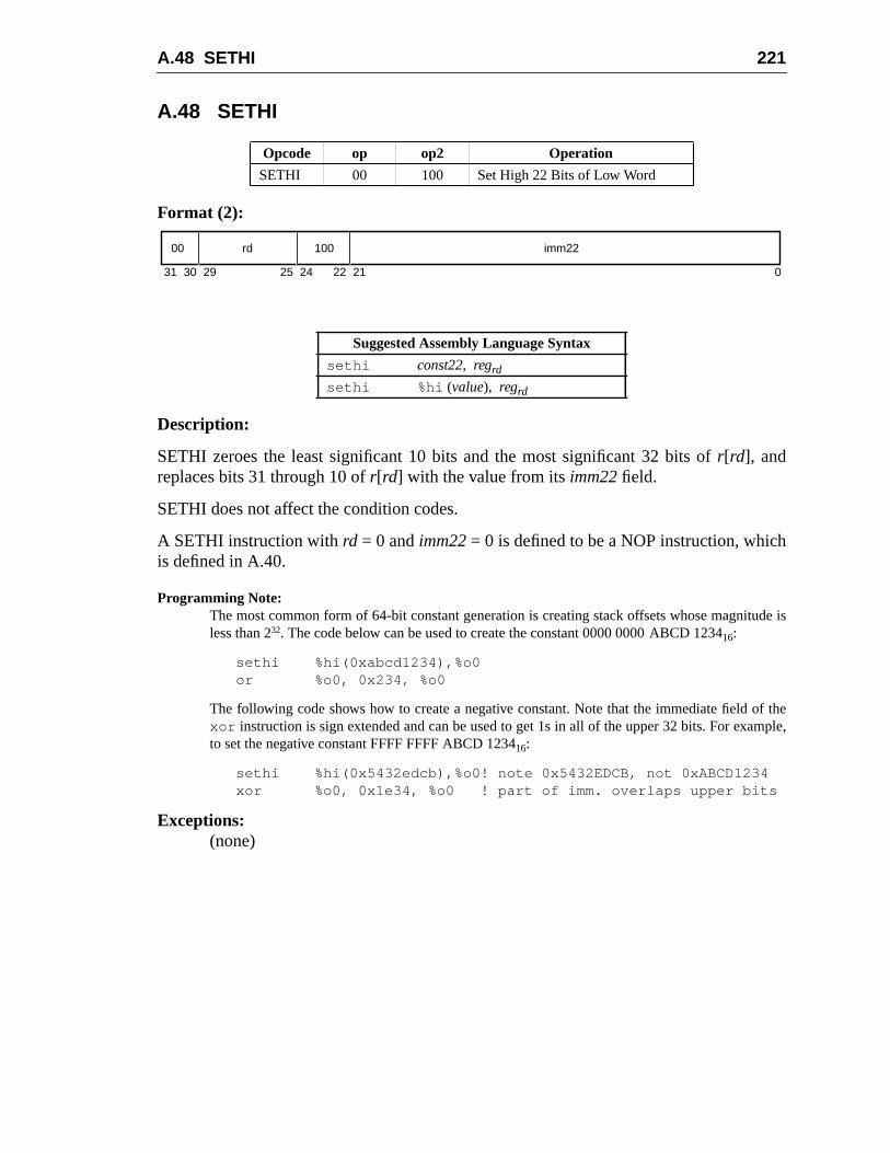
A.48 SETHI 221
h
ude is
of themple,
A.48 SETHI
Format (2):
Description:
SETHI zeroes the least significant 10 bits and the most significant 32 bits ofr[rd], andreplaces bits 31 through 10 ofr[rd] with the value from itsimm22 field.
SETHI does not affect the condition codes.
A SETHI instruction withrd = 0 andimm22= 0 is defined to be a NOP instruction, whicis defined in A.40.
Programming Note:The most common form of 64-bit constant generation is creating stack offsets whose magnitless than 232. The code below can be used to create the constant 0000 0000 ABCD 123416:
sethi %hi(0xabcd1234),%o0or %o0, 0x234, %o0
The following code shows how to create a negative constant. Note that the immediate fieldxor instruction is sign extended and can be used to get 1s in all of the upper 32 bits. For exato set the negative constant FFFF FFFF ABCD 123416:
sethi %hi(0x5432edcb),%o0! note 0x5432EDCB, not 0xABCD1234xor %o0, 0x1e34, %o0 ! part of imm. overlaps upper bits
Exceptions:(none)
Opcode op op2 Operation
SETHI 00 100 Set High 22 Bits of Low Word
Suggested Assembly Language Syntax
sethi const22, regrd
sethi %hi (value), regrd
31 2224 21 02530 29
00 rd 100 imm22
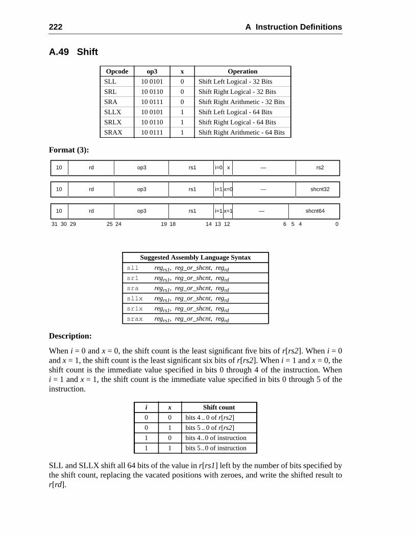
222 A Instruction Definitions
henthe
ult to
A.49 Shift
Format (3):
Description:
Wheni = 0 andx = 0, the shift count is the least significant five bits ofr[rs2]. When i = 0andx = 1, the shift count is the least significant six bits ofr[rs2]. Wheni = 1 andx = 0, theshift count is the immediate value specified in bits 0 through 4 of the instruction. Wi = 1 andx = 1, the shift count is the immediate value specified in bits 0 through 5 ofinstruction.
SLL and SLLX shift all 64 bits of the value inr[rs1] left by the number of bits specified bythe shift count, replacing the vacated positions with zeroes, and write the shifted resr[rd].
Opcode op3 x Operation
SLL 10 0101 0 Shift Left Logical - 32 Bits
SRL 10 0110 0 Shift Right Logical - 32 Bits
SRA 10 0111 0 Shift Right Arithmetic - 32 Bits
SLLX 10 0101 1 Shift Left Logical - 64 Bits
SRLX 10 0110 1 Shift Right Logical - 64 Bits
SRAX 10 0111 1 Shift Right Arithmetic - 64 Bits
Suggested Assembly Language Syntax
sll regrs1, reg_or_shcnt, regrd
srl regrs1, reg_or_shcnt, regrd
sra regrs1, reg_or_shcnt, regrd
sllx regrs1, reg_or_shcnt, regrd
srlx regrs1, reg_or_shcnt, regrd
srax regrs1, reg_or_shcnt, regrd
i x Shift count
0 0 bits 4 .. 0 ofr[rs2]
0 1 bits 5 .. 0 ofr[rs2]
1 0 bits 4..0 of instruction
1 1 bits 5..0 of instruction
31 24 02530 29 19 18
rd10 op3 —
14 13 12 5 4
rs1 rs2i=0 x
rd10 op3 —rs1 shcnt32i=1 x=0
rd10 op3 —rs1 shcnt64i=1 x=1
6
A.49 Shift 223
sult is
ifted
e 32-
.
n-
SRL shifts the low 32 bits of the value inr[rs1] right by the number of bits specified by theshift count. Zeroes are shifted into bit 31. The upper 32 bits are set to zero, and the rewritten tor[rd].
SRLX shifts all 64 bits of the value inr[rs1] right by the number of bits specified by theshift count. Zeroes are shifted into the vacated high-order bit positions, and the shresult is written tor[rd].
SRA shifts the low 32 bits of the value inr[rs1] right by the number of bits specified bythe shift count, and replaces the vacated positions with bit 31 ofr[rs1]. The high order 32bits of the result are all set with bit 31 ofr[rs1], and the result is written tor[rd].
SRAX shifts all 64 bits of the value inr[rs1] right by the number of bits specified by theshift count, and replaces the vacated positions with bit 63 ofr[rs1]. The shifted result iswritten tor[rd].
No shift occurs when the shift count is zero, but the high-order bits are affected by thbit shifts as noted above.
These instructions do not modify the condition codes.
Programming Note:“Arithmetic left shift by 1 (and calculate overflow)” can be effected with the ADDcc instruction
Programming Note:The instruction “sra rs1,0, rd” can be used to convert a 32-bit value to 64 bits, with sign extesion into the upper word. “srl rs1,0, rd” can be used to clear the upper 32 bits ofr[rd].
Exceptions:(none)
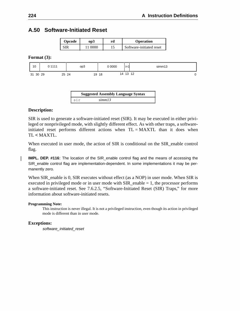
224 A Instruction Definitions
privi-re-
en
ntrol
IR isforms
ore
ged
A.50 Software-Initiated Reset
Format (3):
Description:
SIR is used to generate a software-initiated reset (SIR). It may be executed in eitherleged or nonprivileged mode, with slightly different effect. As with other traps, a softwainitiated reset performs different actions when TL = MAXTL than it does whTL < MAXTL.
When executed in user mode, the action of SIR is conditional on the SIR_enable coflag.
IMPL. DEP. #116: The location of the SIR_enable control flag and the means of accessing theSIR_enable control flag are implementation-dependent. In some implementations it may be per-manently zero.
When SIR_enable is 0, SIR executes without effect (as a NOP) in user mode. When Sexecuted in privileged mode or in user mode with SIR_enable = 1, the processor pera software-initiated reset. See 7.6.2.5, “Software-Initiated Reset (SIR) Traps,” for minformation about software-initiated resets.
Programming Note:This instruction is never illegal. It is not a privileged instruction, even though its action in privilemode is different than in user mode.
Exceptions:software_initiated_reset
Opcode op3 rd Operation
SIR 11 0000 15 Software-initiated reset
Suggested Assembly Language Syntax
sir simm13
31 1924 18 02530 29
10 0 1111 op3
14 13
0 0000 simm13
12
i=1
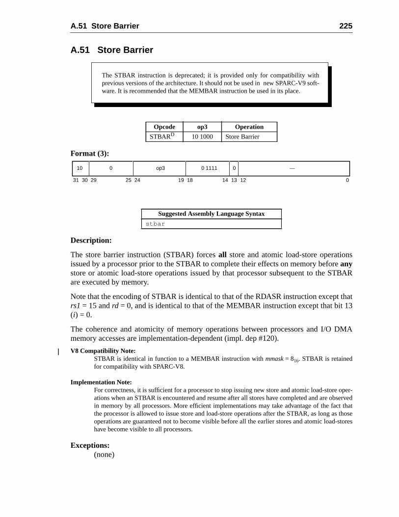
A.51 Store Barrier 225
s
TBAR
that3
DMA
oper-served
t thats those-stores
A.51 Store Barrier
Format (3):
Description:
The store barrier instruction (STBAR) forcesall store and atomic load-store operationissued by a processor prior to the STBAR to complete their effects on memory beforeanystore or atomic load-store operations issued by that processor subsequent to the Sare executed by memory.
Note that the encoding of STBAR is identical to that of the RDASR instruction exceptrs1 = 15 andrd = 0, and is identical to that of the MEMBAR instruction except that bit 1(i) = 0.
The coherence and atomicity of memory operations between processors and I/Omemory accesses are implementation-dependent (impl. dep #120).
V8 Compatibility Note:STBAR is identical in function to a MEMBAR instruction withmmask= 816. STBAR is retainedfor compatibility with SPARC-V8.
Implementation Note:For correctness, it is sufficient for a processor to stop issuing new store and atomic load-storeations when an STBAR is encountered and resume after all stores have completed and are obin memory by all processors. More efficient implementations may take advantage of the facthe processor is allowed to issue store and load-store operations after the STBAR, as long aoperations are guaranteed not to become visible before all the earlier stores and atomic loadhave become visible to all processors.
Exceptions:(none)
Opcode op3 Operation
STBARD 10 1000 Store Barrier
Suggested Assembly Language Syntax
stbar
The STBAR instruction is deprecated; it is provided only for compatibility withprevious versions of the architecture. It should not be used in new SPARC-V9 soft-ware. It is recommended that the MEMBAR instruction be used in its place.
31 141924 18 13 02530 29
10 0 op3 0 1111 —
12
0
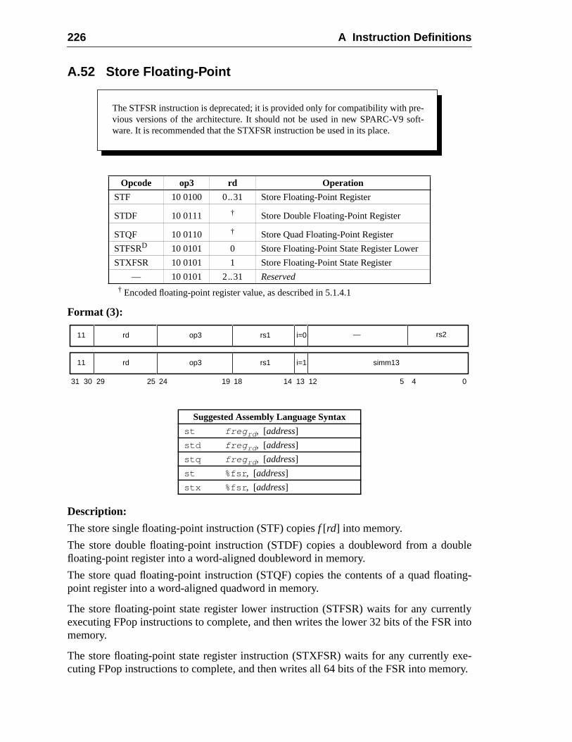
226 A Instruction Definitions
uble
ting-
ntlyR into
exe-ory.
A.52 Store Floating-Point
† Encoded floating-point register value, as described in 5.1.4.1
Format (3):
Description:
The store single floating-point instruction (STF) copiesf [rd] into memory.
The store double floating-point instruction (STDF) copies a doubleword from a dofloating-point register into a word-aligned doubleword in memory.
The store quad floating-point instruction (STQF) copies the contents of a quad floapoint register into a word-aligned quadword in memory.
The store floating-point state register lower instruction (STFSR) waits for any curreexecuting FPop instructions to complete, and then writes the lower 32 bits of the FSmemory.
The store floating-point state register instruction (STXFSR) waits for any currentlycuting FPop instructions to complete, and then writes all 64 bits of the FSR into mem
Opcode op3 rd Operation
STF 10 0100 0..31 Store Floating-Point Register
STDF 10 0111 † Store Double Floating-Point Register
STQF 10 0110 † Store Quad Floating-Point Register
STFSRD 10 0101 0 Store Floating-Point State Register Lower
STXFSR 10 0101 1 Store Floating-Point State Register
— 10 0101 2..31 Reserved
Suggested Assembly Language Syntax
st freg rd , [address]
std freg rd , [address]
stq freg rd , [address]
st %fsr , [address]
stx %fsr , [address]
The STFSR instruction is deprecated; it is provided only for compatibility with pre-vious versions of the architecture. It should not be used in new SPARC-V9 soft-ware. It is recommended that the STXFSR instruction be used in its place.
31 24 02530 29 19 18 14 13 12 5 4
rd11 op3 rs1 simm13i=1
rd11 op3 rs1 i=0 — rs2
A.52 Store Floating-Point 227
ed toll 64
fort, a
deter-ion of-preci-
V8 Compatibility Note:SPARC-V9 needs two store-FSR instructions, since the SPARC-V8 STFSR instruction is definstore only 32 bits of the FSR into memory. STXFSR allows SPARC-V9 programs to store abits of the FSR.
STFSR and STXFSR zero FSR.ftt after writing the FSR to memory.
Implementation Note:FSR.ftt should not be zeroed until it is known that the store will not cause a precise trap.
The effective address for these instructions is “r[rs1] + r[rs2]” if i = 0, or “r[rs1] + sign_ext(simm13)” if i = 1.
STF, STFSR, STDF, and STQF cause amem_address_not_aligned exception if the effectivememory address is not word-aligned; STXFSR causes amem_address_not_aligned excep-tion if the address is not doubleword-aligned. If the floating-point unit is not enabledthe source registerrd (per FPRS.FEF and PSTATE.PEF), or if the FPU is not presenstore floating-point instruction causes anfp_disabled exception.
IMPL. DEP. #110(1): STDF requires only word alignment in memory. If the effective address isword-aligned but not doubleword-aligned, it may cause an STDF_mem_address_not_alignedexception. In this case the trap handler software shall emulate the STDF instruction and return.
IMPL. DEP. #112(1): STQF requires only word alignment in memory. If the effective address isword-aligned but not quadword-aligned, it may cause an STQF_mem_address_not_alignedexception. In this case the trap handler software shall emulate the STQF instruction and return.
Programming Note:In SPARC-V8, some compilers issued sets of single-precision stores when they could notmine that double- or quadword operands were properly aligned. For SPARC-V9, since emulatmisaligned stores is expected to be fast, it is recommended that compilers issue sets of singlesion stores only when they can determine that double- or quadword operands arenot properlyaligned.
Exceptions:async_data_errorfp_disabledmem_address_not_alignedSTDF_mem_address_not_aligned (STDF only) (impl. dep. #110)STQF_mem_address_not_aligned (STQF only) (impl. dep. #112)data_access_exceptiondata_access_protectiondata_access_MMU_missdata_access_errorillegal_instruction (op3= 2516 andrd = 2..31)fp_exception_other (invalid_fp_register (STQF only))
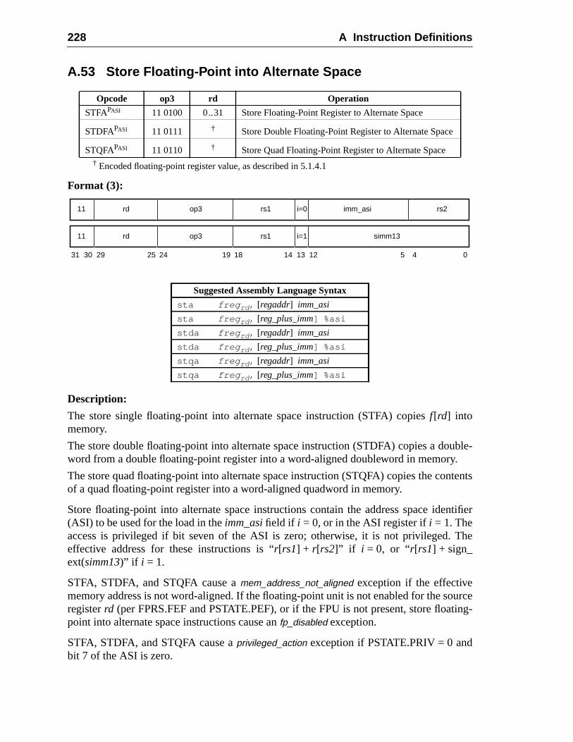
228 A Instruction Definitions
uble-.
tents
ntifier
The
urceting-
A.53 Store Floating-Point into Alternate Space
† Encoded floating-point register value, as described in 5.1.4.1
Format (3):
Description:
The store single floating-point into alternate space instruction (STFA) copiesf[rd] intomemory.
The store double floating-point into alternate space instruction (STDFA) copies a doword from a double floating-point register into a word-aligned doubleword in memory
The store quad floating-point into alternate space instruction (STQFA) copies the conof a quad floating-point register into a word-aligned quadword in memory.
Store floating-point into alternate space instructions contain the address space ide(ASI) to be used for the load in theimm_asifield if i = 0, or in the ASI register ifi = 1. Theaccess is privileged if bit seven of the ASI is zero; otherwise, it is not privileged.effective address for these instructions is “r[rs1] + r[rs2]” if i = 0, or “r[rs1] + sign_ext(simm13)” if i = 1.
STFA, STDFA, and STQFA cause amem_address_not_aligned exception if the effectivememory address is not word-aligned. If the floating-point unit is not enabled for the soregisterrd (per FPRS.FEF and PSTATE.PEF), or if the FPU is not present, store floapoint into alternate space instructions cause anfp_disabled exception.
STFA, STDFA, and STQFA cause aprivileged_action exception if PSTATE.PRIV = 0 andbit 7 of the ASI is zero.
Opcode op3 rd Operation
STFAPASI 11 0100 0..31 Store Floating-Point Register to Alternate Space
STDFAPASI 11 0111 † Store Double Floating-Point Register to Alternate Space
STQFAPASI 11 0110 † Store Quad Floating-Point Register to Alternate Space
Suggested Assembly Language Syntax
sta freg rd , [regaddr] imm_asi
sta freg rd , [reg_plus_imm] %asi
stda freg rd , [regaddr] imm_asi
stda freg rd , [reg_plus_imm] %asi
stqa freg rd , [regaddr] imm_asi
stqa freg rd , [reg_plus_imm] %asi
31 24 02530 29 19 18
rd11 op3 imm_asi
14 13 12 5 4
rs1 rs2i=0
rd11 op3 rs1 simm13i=1
A.53 Store Floating-Point into Alternate Space 229
deter-ion of-preci-
IMPL. DEP. #110(2): STDFA requires only word alignment in memory. If the effective address isword-aligned but not doubleword-aligned, it may cause an STDF_mem_address_not_alignedexception. In this case the trap handler software shall emulate the STDFA instruction and return.
IMPL. DEP. #112(2): STQFA requires only word alignment in memory. If the effective address isword-aligned but not quadword-aligned, it may cause an STQF_mem_address_not_alignedexception. In this case the trap handler software shall emulate the STQFA instruction and return.
Programming Note:In SPARC-V8, some compilers issued sets of single-precision stores when they could notmine that double- or quadword operands were properly aligned. For SPARC-V9, since emulatmisaligned stores is expected to be fast, it is recommended that compilers issue sets of singlesion stores only when they can determine that double- or quadword operands arenot properlyaligned.
Exceptions:async_data_errorfp_disabledmem_address_not_alignedSTDF_mem_address_not_aligned (STDFA only) (impl. dep. #110)STQF_mem_address_not_aligned (STQFA only) (impl. dep. #112)privileged_actiondata_access_exceptiondata_access_protectiondata_access_MMU_missdata_access_errorfp_exception_other (invalid_fp_register (STQFA only))
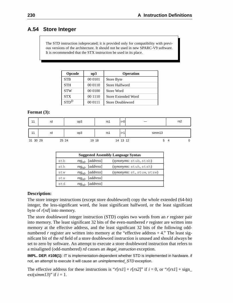
230 A Instruction Definitions
4-bit)cant
odd-sig-
beers to
A.54 Store Integer
Format (3):
Description:The store integer instructions (except store doubleword) copy the whole extended (6integer, the less-significant word, the least significant halfword, or the least signifibyte ofr[rd] into memory.
The store doubleword integer instruction (STD) copies two words from anr register pairinto memory. The least significant 32 bits of the even-numberedr register are written intomemory at the effective address, and the least significant 32 bits of the followingnumberedr register are written into memory at the “effective address + 4.” The leastnificant bit of therd field of a store doubleword instruction is unused and should alwaysset to zero by software. An attempt to execute a store doubleword instruction that refa misaligned (odd-numbered)rd causes anillegal_instruction exception.
IMPL. DEP. #108(1): IT is implementation-dependent whether STD is implemented in hardware. ifnot, an attempt to execute it will cause an unimplemented_STD exception.
The effective address for these instructions is “r[rs1] + r[rs2]” if i = 0, or “r[rs1] + sign_ext(simm13)” if i = 1.
Opcode op3 Operation
STB 00 0101 Store Byte
STH 00 0110 Store Halfword
STW 00 0100 Store Word
STX 00 1110 Store Extended Word
STDD 00 0111 Store Doubleword
Suggested Assembly Language Syntax
stb regrd, [address] (synonyms: stub , stsb )
sth regrd, [address] (synonyms: stuh , stsh )
stw regrd, [address] (synonyms: st , stuw , stsw )
stx regrd, [address]
std regrd, [address]
The STD instruction isdeprecated; it is provided only for compatibility with previ-ous versions of the architecture. It should not be used in new SPARC-V9 software.It is recommended that the STX instruction be used in its place.
31 24 02530 29 19 18 14 13 12 5 4
rd11 op3 rs1 simm13i=1
rd11 op3 rs1 i=0 — rs2
A.54 Store Integer 231
erates
-t
d ofinto
esause a
A successful store (notably, store extended and store doubleword) instruction opatomically.
STH causes amem_address_not_aligned exception if the effective address is not halfwordaligned. STW causes amem_address_not_aligned exception if the effective address is noword-aligned. STX and STD causes amem_address_not_aligned exception if the effectiveaddress is not doubleword-aligned.
With respect to little-endian memory, a STD instruction behaves as if it is composetwo 32-bit stores, each of which is byte-swapped independently before being writteneach destination memory word.
Programming Note:STD is provided for compatibility with SPARC-V8. It may execute slowly on SPARC-V9 machinbecause of data path and register-access difficulties. In some SPARC-V9 systems it may ctrap to emulation code; therefore, STD should be avoided.
If STD is emulated in software, STX should be used in order to preserve atomicity.
V8 Compatibility Note:The SPARC-V8 ST instruction has been renamed STW in SPARC-V9.
Exceptions:async_data_errorunimplemented_STD (STD only) (impl. dep. #108)illegal_instruction (STD with oddrd)mem_address_not_aligned (all except STB)data_access_exceptiondata_access_errordata_access_protectiondata_access_MMU_miss
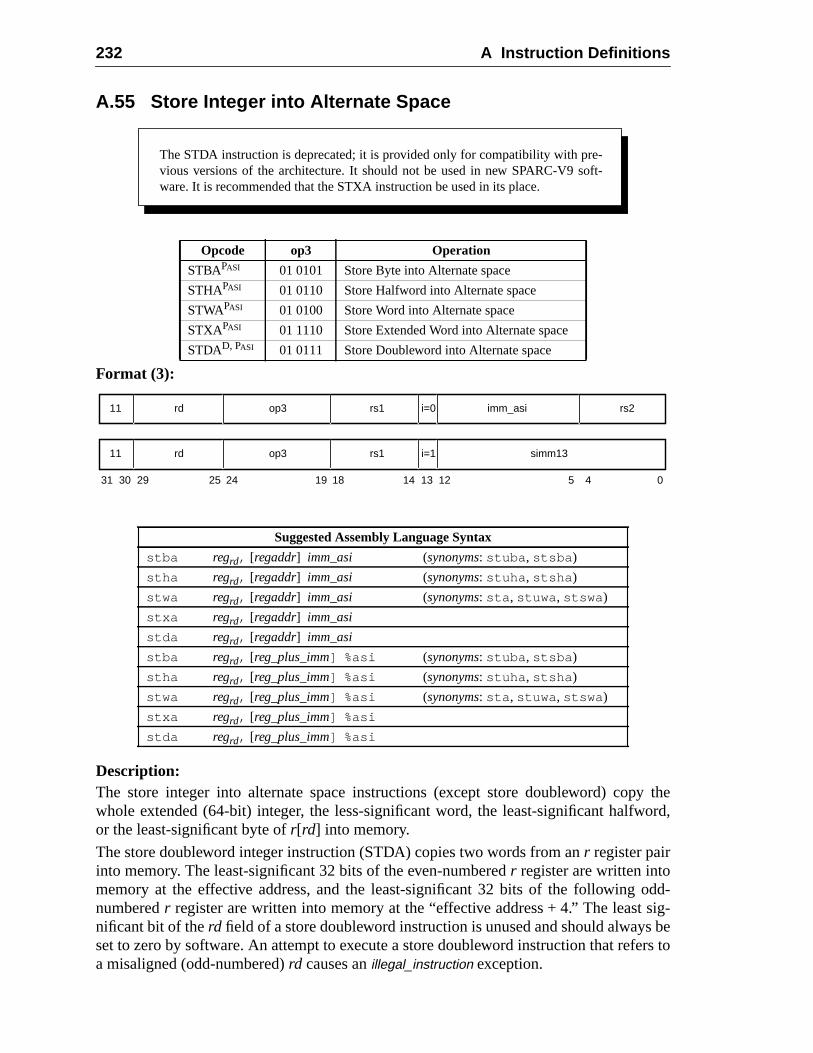
232 A Instruction Definitions
y theord,
odd-sig-
beers to
A.55 Store Integer into Alternate Space
Format (3):
Description:The store integer into alternate space instructions (except store doubleword) copwhole extended (64-bit) integer, the less-significant word, the least-significant halfwor the least-significant byte ofr[rd] into memory.
The store doubleword integer instruction (STDA) copies two words from anr register pairinto memory. The least-significant 32 bits of the even-numberedr register are written intomemory at the effective address, and the least-significant 32 bits of the followingnumberedr register are written into memory at the “effective address + 4.” The leastnificant bit of therd field of a store doubleword instruction is unused and should alwaysset to zero by software. An attempt to execute a store doubleword instruction that refa misaligned (odd-numbered)rd causes anillegal_instruction exception.
Opcode op3 Operation
STBAPASI 01 0101 Store Byte into Alternate space
STHAPASI 01 0110 Store Halfword into Alternate space
STWAPASI 01 0100 Store Word into Alternate space
STXAPASI 01 1110 Store Extended Word into Alternate space
STDAD, PASI 01 0111 Store Doubleword into Alternate space
Suggested Assembly Language Syntax
stba regrd, [regaddr] imm_asi (synonyms: stuba , stsba )
stha regrd, [regaddr] imm_asi (synonyms: stuha , stsha )
stwa regrd, [regaddr] imm_asi (synonyms: sta , stuwa , stswa )
stxa regrd, [regaddr] imm_asi
stda regrd, [regaddr] imm_asi
stba regrd, [reg_plus_imm] %asi (synonyms: stuba , stsba )
stha regrd, [reg_plus_imm] %asi (synonyms: stuha , stsha )
stwa regrd, [reg_plus_imm] %asi (synonyms: sta , stuwa , stswa )
stxa regrd, [reg_plus_imm] %asi
stda regrd, [reg_plus_imm] %asi
The STDA instruction is deprecated; it is provided only for compatibility with pre-vious versions of the architecture. It should not be used in new SPARC-V9 soft-ware. It is recommended that the STXA instruction be used in its place.
31 24 02530 29 19 18
rd11 op3 imm_asi
14 13 12 5 4
rs1 rs2i=0
rd11 op3 rs1 simm13i=1
A.55 Store Integer into Alternate Space 233
) to be
ive
erates
f-
d ofinto
9it may
IMPL. DEP. #108(2): It is implementation-dependent whether STDA is implemented in hardware. Ifnot, an attempt to execute it will cause an unimplemented_STD exception.
Store integer to alternate space instructions contain the address space identifier (ASIused for the store in theimm_asifield if i = 0, or in the ASI register ifi = 1. The access isprivileged if bit seven of the ASI is zero; otherwise, it is not privileged. The effectaddress for these instructions is “r[rs1] + r[rs2]” if i = 0, or “r[rs1]+sign_ext(simm13)” ifi = 1.
A successful store (notably, store extended and store doubleword) instruction opatomically.
STHA causes amem_address_not_aligned exception if the effective address is not halword-aligned. STWA causes amem_address_not_aligned exception if the effective addressis not word-aligned. STXA and STDA cause amem_address_not_aligned exception if theeffective address is not doubleword-aligned.
A store integer into alternate space instruction causes aprivileged_action exception ifPSTATE.PRIV = 0 and bit 7 of the ASI is zero.
With respect to little-endian memory, a STDA instruction behaves as if it is composetwo 32-bit stores, each of which is byte-swapped independently before being writteneach destination memory word.
Programming Note:STDA is provided for compatibility with SPARC-V8. It may execute slowly on SPARC-Vmachines because of data path and register-access difficulties. In some SPARC-V9 systemscause a trap to emulation code; therefore, STDA should be avoided.
If STDA is emulated in software, STXA should be used in order to preserve atomicity.
V8 Compatibility Note:The SPARC-V8 STA instruction is renamed STWA in SPARC-V9.
Exceptions:async_data_errorunimplemented_STD (STDA only) (impl. dep. #108)illegal_instruction (STDA with oddrd)privileged_actionmem_address_not_aligned (all except STBA)data_access_exceptiondata_access_errordata_access_protectiondata_access_MMU_miss
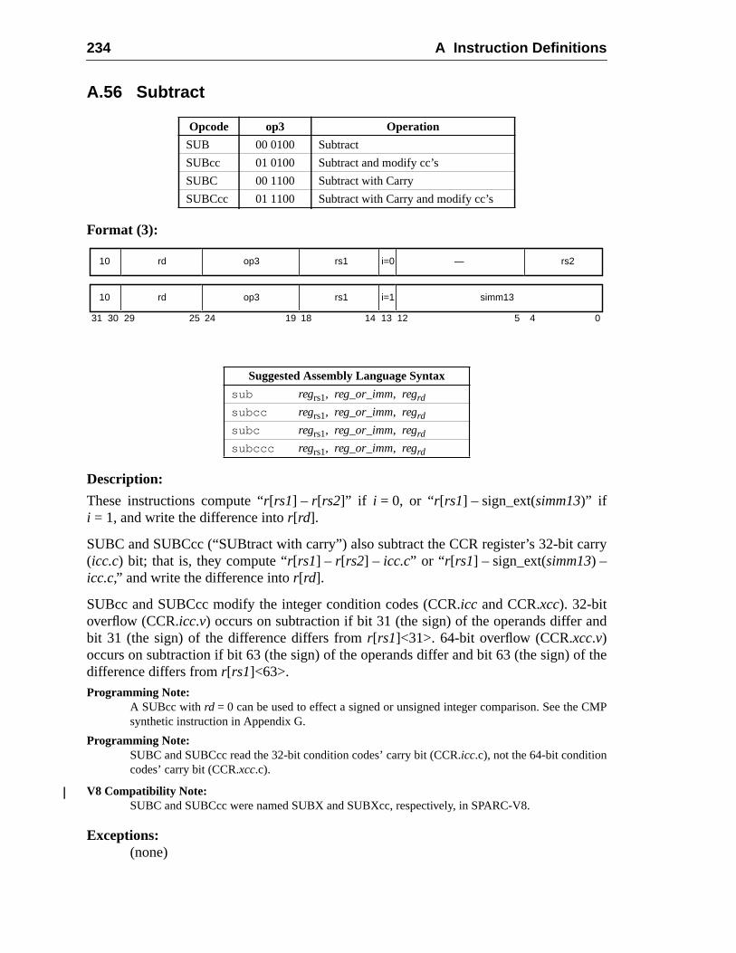
234 A Instruction Definitions
rry
nd
f the
CMP
A.56 Subtract
Format (3):
Description:
These instructions compute “r[rs1] – r[rs2]” if i = 0, or “r[rs1] – sign_ext(simm13)” ifi = 1, and write the difference intor[rd].
SUBC and SUBCcc (“SUBtract with carry”) also subtract the CCR register’s 32-bit ca(icc.c) bit; that is, they compute “r[rs1] – r[rs2] – icc.c” or “ r[rs1] – sign_ext(simm13) –icc.c,” and write the difference intor[rd].
SUBcc and SUBCcc modify the integer condition codes (CCR.icc and CCR.xcc). 32-bitoverflow (CCR.icc.v) occurs on subtraction if bit 31 (the sign) of the operands differ abit 31 (the sign) of the difference differs fromr[rs1]<31>. 64-bit overflow (CCR.xcc.v)occurs on subtraction if bit 63 (the sign) of the operands differ and bit 63 (the sign) odifference differs fromr[rs1]<63>.Programming Note:
A SUBcc with rd = 0 can be used to effect a signed or unsigned integer comparison. See thesynthetic instruction in Appendix G.
Programming Note:SUBC and SUBCcc read the 32-bit condition codes’ carry bit (CCR.icc.c), not the 64-bit conditioncodes’ carry bit (CCR.xcc.c).
V8 Compatibility Note:SUBC and SUBCcc were named SUBX and SUBXcc, respectively, in SPARC-V8.
Exceptions:(none)
Opcode op3 Operation
SUB 00 0100 Subtract
SUBcc 01 0100 Subtract and modify cc’s
SUBC 00 1100 Subtract with Carry
SUBCcc 01 1100 Subtract with Carry and modify cc’s
Suggested Assembly Language Syntax
sub regrs1, reg_or_imm, regrd
subcc regrs1, reg_or_imm, regrd
subc regrs1, reg_or_imm, regrd
subccc regrs1, reg_or_imm, regrd
31 24 02530 29 19 18
rd10 op3 —
14 13 12 5 4
rs1 rs2i=0
rd10 op3 rs1 simm13i=1
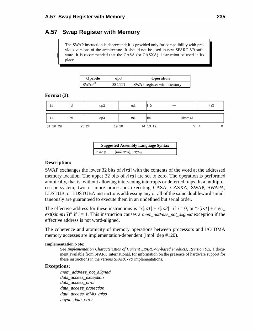
A.57 Swap Register with Memory 235
ddro-PA,ul-
DMA
rt for
A.57 Swap Register with Memory
Format (3):
Description:
SWAP exchanges the lower 32 bits ofr[rd] with the contents of the word at the addressememory location. The upper 32 bits ofr[rd] are set to zero. The operation is performeatomically, that is, without allowing intervening interrupts or deferred traps. In a multipcessor system, two or more processors executing CASA, CASXA, SWAP, SWALDSTUB, or LDSTUBA instructions addressing any or all of the same doubleword simtaneously are guaranteed to execute them in an undefined but serial order.
The effective address for these instructions is “r[rs1] + r[rs2]” if i = 0, or “r[rs1] + sign_ext(simm13)” if i = 1. This instruction causes amem_address_not_aligned exception if theeffective address is not word-aligned.
The coherence and atomicity of memory operations between processors and I/Omemory accesses are implementation-dependent (impl. dep #120).
Implementation Note:SeeImplementation Characteristics of Current SPARC-V9-based Products, Revision 9.x, a docu-ment available from SPARC International, for information on the presence of hardware suppothese instructions in the various SPARC-V9 implementations.
Exceptions:mem_address_not_aligneddata_access_exceptiondata_access_errordata_access_protectiondata_access_MMU_missasync_data_error
Opcode op3 Operation
SWAPD 00 1111 SWAP register with memory
Suggested Assembly Language Syntax
swap [address], regrd
The SWAP instruction is deprecated; it is provided only for compatibility with pre-vious versions of the architecture. It should not be used in new SPARC-V9 soft-ware. It is recommended that the CASA (or CASXA) instruction be used in itsplace.
31 24 02530 29 19 18 14 13 12 5 4
rd11 op3 rs1 simm13i=1
rd11 op3 rs1 i=0 — rs2
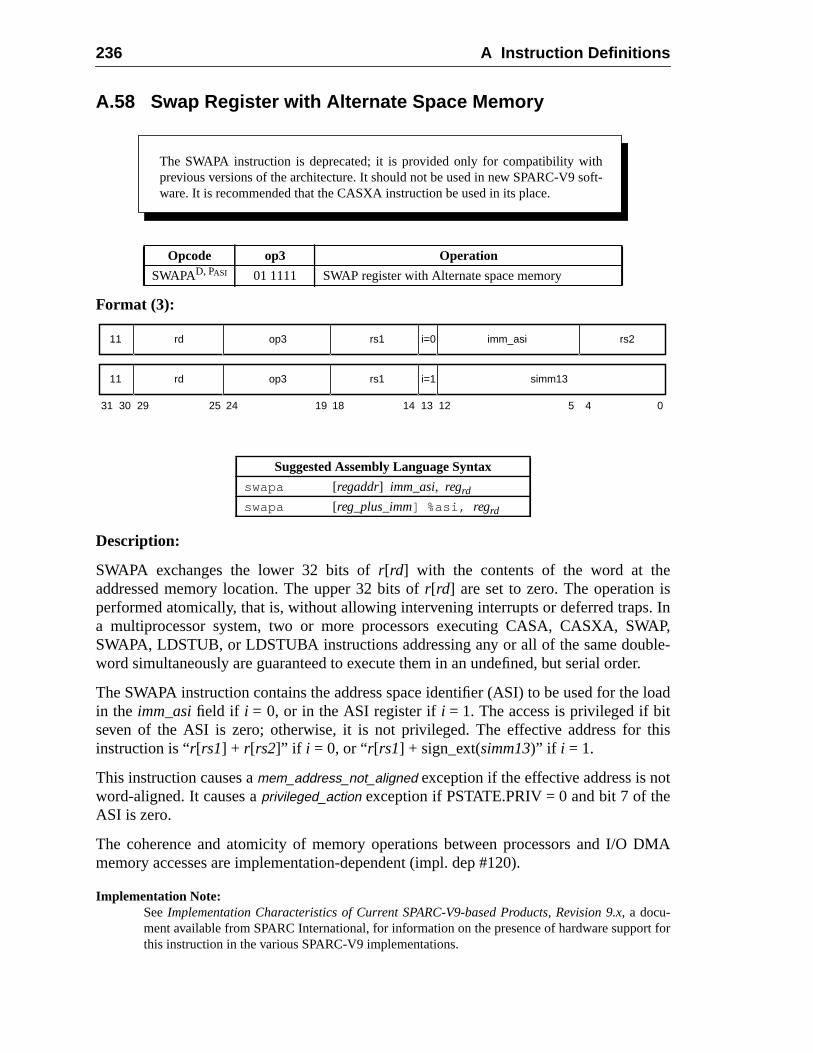
236 A Instruction Definitions
s. InAP,le-
er.
load
this
t
DMA
rt for
A.58 Swap Register with Alternate Space Memory
Format (3):
Description:
SWAPA exchanges the lower 32 bits ofr[rd] with the contents of the word at theaddressed memory location. The upper 32 bits ofr[rd] are set to zero. The operation iperformed atomically, that is, without allowing intervening interrupts or deferred trapsa multiprocessor system, two or more processors executing CASA, CASXA, SWSWAPA, LDSTUB, or LDSTUBA instructions addressing any or all of the same doubword simultaneously are guaranteed to execute them in an undefined, but serial ord
The SWAPA instruction contains the address space identifier (ASI) to be used for thein the imm_asifield if i = 0, or in the ASI register ifi = 1. The access is privileged if bitseven of the ASI is zero; otherwise, it is not privileged. The effective address forinstruction is “r[rs1] + r[rs2]” if i = 0, or “r[rs1] + sign_ext(simm13)” if i = 1.
This instruction causes amem_address_not_aligned exception if the effective address is noword-aligned. It causes aprivileged_action exception if PSTATE.PRIV = 0 and bit 7 of theASI is zero.
The coherence and atomicity of memory operations between processors and I/Omemory accesses are implementation-dependent (impl. dep #120).
Implementation Note:SeeImplementation Characteristics of Current SPARC-V9-based Products, Revision 9.x, a docu-ment available from SPARC International, for information on the presence of hardware suppothis instruction in the various SPARC-V9 implementations.
Opcode op3 Operation
SWAPAD, PASI 01 1111 SWAP register with Alternate space memory
Suggested Assembly Language Syntax
swapa [regaddr] imm_asi, regrd
swapa [reg_plus_imm] %asi, regrd
The SWAPA instruction is deprecated; it is provided only for compatibility withprevious versions of the architecture. It should not be used in new SPARC-V9 soft-ware. It is recommended that the CASXA instruction be used in its place.
31 24 02530 29 19 18
rd11 op3 imm_asi
14 13 12 5 4
rs1 rs2i=0
rd11 op3 rs1 simm13i=1
A.58 Swap Register with Alternate Space Memory 237
Exceptions:mem_address_not_alignedprivileged_actiondata_access_exceptiondata_access_errordata_access_protectiondata_access_MMU_missasync_data_error
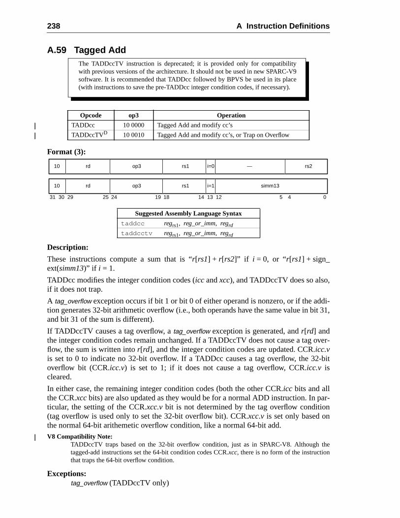
238 A Instruction Definitions
di-it 31,
over-
-bit
ar-n
the
A.59 Tagged Add
Format (3):
Description:
These instructions compute a sum that is “r[rs1] + r[rs2]” if i = 0, or “r[rs1] + sign_ext(simm13)” if i = 1.
TADDcc modifies the integer condition codes (icc andxcc), and TADDccTV does so also,if it does not trap.
A tag_overflow exception occurs if bit 1 or bit 0 of either operand is nonzero, or if the adtion generates 32-bit arithmetic overflow (i.e., both operands have the same value in band bit 31 of the sum is different).
If TADDccTV causes a tag overflow, atag_overflow exception is generated, andr[rd] andthe integer condition codes remain unchanged. If a TADDccTV does not cause a tagflow, the sum is written intor[rd], and the integer condition codes are updated. CCR.icc.vis set to 0 to indicate no 32-bit overflow. If a TADDcc causes a tag overflow, the 32overflow bit (CCR.icc.v) is set to 1; if it does not cause a tag overflow, CCR.icc.v iscleared.
In either case, the remaining integer condition codes (both the other CCR.icc bits and allthe CCR.xccbits) are also updated as they would be for a normal ADD instruction. In pticular, the setting of the CCR.xcc.vbit is not determined by the tag overflow conditio(tag overflow is used only to set the 32-bit overflow bit). CCR.xcc.v is set only based onthe normal 64-bit arithemetic overflow condition, like a normal 64-bit add.V8 Compatibility Note:
TADDccTV traps based on the 32-bit overflow condition, just as in SPARC-V8. Althoughtagged-add instructions set the 64-bit condition codes CCR.xcc, there is no form of the instructionthat traps the 64-bit overflow condition.
Exceptions:tag_overflow (TADDccTV only)
Opcode op3 Operation
TADDcc 10 0000 Tagged Add and modify cc’s
TADDccTVD 10 0010 Tagged Add and modify cc’s, or Trap on Overflow
Suggested Assembly Language Syntax
taddcc regrs1, reg_or_imm, regrd
taddcctv regrs1, reg_or_imm, regrd
The TADDccTV instruction is deprecated; it is provided only for compatibilitywith previous versions of the architecture. It should not be used in new SPARC-V9software. It is recommended that TADDcc followed by BPVS be used in its place(with instructions to save the pre-TADDcc integer condition codes, if necessary).
31 24 02530 29 19 18
rd10 op3 —
14 13 12 5 4
rs1 rs2i=0
rd10 op3 rs1 simm13i=1
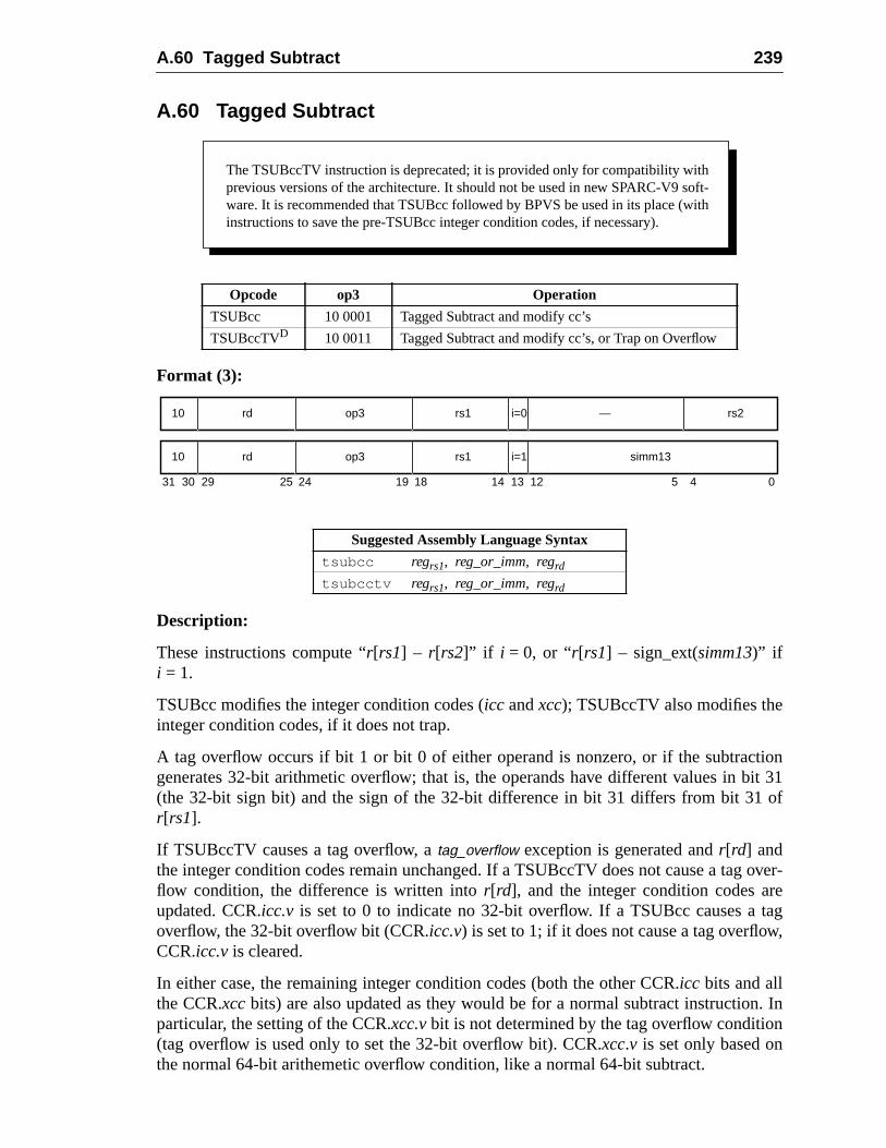
A.60 Tagged Subtract 239
tionit 31of
over-etag,
n. Inn
A.60 Tagged Subtract
Format (3):
Description:
These instructions compute “r[rs1] – r[rs2]” if i = 0, or “r[rs1] – sign_ext(simm13)” ifi = 1.
TSUBcc modifies the integer condition codes (icc andxcc); TSUBccTV also modifies theinteger condition codes, if it does not trap.
A tag overflow occurs if bit 1 or bit 0 of either operand is nonzero, or if the subtracgenerates 32-bit arithmetic overflow; that is, the operands have different values in b(the 32-bit sign bit) and the sign of the 32-bit difference in bit 31 differs from bit 31r[rs1].
If TSUBccTV causes a tag overflow, atag_overflow exception is generated andr[rd] andthe integer condition codes remain unchanged. If a TSUBccTV does not cause a tagflow condition, the difference is written intor[rd], and the integer condition codes arupdated. CCR.icc.v is set to 0 to indicate no 32-bit overflow. If a TSUBcc causes aoverflow, the 32-bit overflow bit (CCR.icc.v) is set to 1; if it does not cause a tag overflowCCR.icc.v is cleared.
In either case, the remaining integer condition codes (both the other CCR.icc bits and allthe CCR.xccbits) are also updated as they would be for a normal subtract instructioparticular, the setting of the CCR.xcc.vbit is not determined by the tag overflow conditio(tag overflow is used only to set the 32-bit overflow bit). CCR.xcc.v is set only based onthe normal 64-bit arithemetic overflow condition, like a normal 64-bit subtract.
Opcode op3 Operation
TSUBcc 10 0001 Tagged Subtract and modify cc’s
TSUBccTVD 10 0011 Tagged Subtract and modify cc’s, or Trap on Overflow
Suggested Assembly Language Syntax
tsubcc regrs1, reg_or_imm, regrd
tsubcctv regrs1, reg_or_imm, regrd
The TSUBccTV instruction is deprecated; it is provided only for compatibility withprevious versions of the architecture. It should not be used in new SPARC-V9 soft-ware. It is recommended that TSUBcc followed by BPVS be used in its place (withinstructions to save the pre-TSUBcc integer condition codes, if necessary).
31 24 02530 29 19 18
rd10 op3 —
14 13 12 5 4
rs1 rs2i=0
rd10 op3 rs1 simm13i=1
240 A Instruction Definitions
the
V8 Compatibility Note:TSUBccTV traps are based on the 32-bit overflow condition, just as in SPARC-V8. Althoughtagged-subtract instructions set the 64-bit condition codes CCR.xcc, there is no form of the instruc-tion that traps on 64-bit overflow.
Exceptions:tag_overflow (TSUBccTV only)
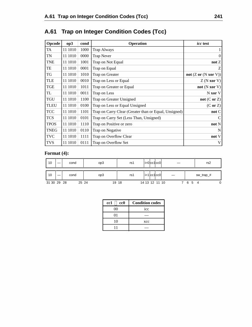
A.61 Trap on Integer Condition Codes (Tcc) 241
C
A.61 Trap on Integer Condition Codes (Tcc)
Format (4):
Opcode op3 cond Operation icc test
TA 11 1010 1000 Trap Always 1
TN 11 1010 0000 Trap Never 0
TNE 11 1010 1001 Trap on Not Equal not Z
TE 11 1010 0001 Trap on Equal Z
TG 11 1010 1010 Trap on Greater not (Z or (N xor V))
TLE 11 1010 0010 Trap on Less or Equal Z (N xor V)
TGE 11 1010 1011 Trap on Greater or Equal not (N xor V)
TL 11 1010 0011 Trap on Less N xor V
TGU 11 1010 1100 Trap on Greater Unsigned not (C or Z)
TLEU 11 1010 0100 Trap on Less or Equal Unsigned (C or Z)
TCC 11 1010 1101 Trap on Carry Clear(Greater than or Equal, Unsigned) not C
TCS 11 1010 0101 Trap on Carry Set (Less Than, Unsigned)
TPOS 11 1010 1110 Trap on Positive or zero not N
TNEG 11 1010 0110 Trap on Negative N
TVC 11 1010 1111 Trap on Overflow Clear not V
TVS 11 1010 0111 Trap on Overflow Set V
cc1 cc0 Condition codes
00 icc
01 —
10 xcc
11 —
5 4
10 cond op3 rs1 i=0 — rs2
31 141924 18 13 12 02530 29
—
28 7 6
cc1cc0
11 10
10 cond op3 rs1 i=1 —— cc1cc0 sw_trap_#
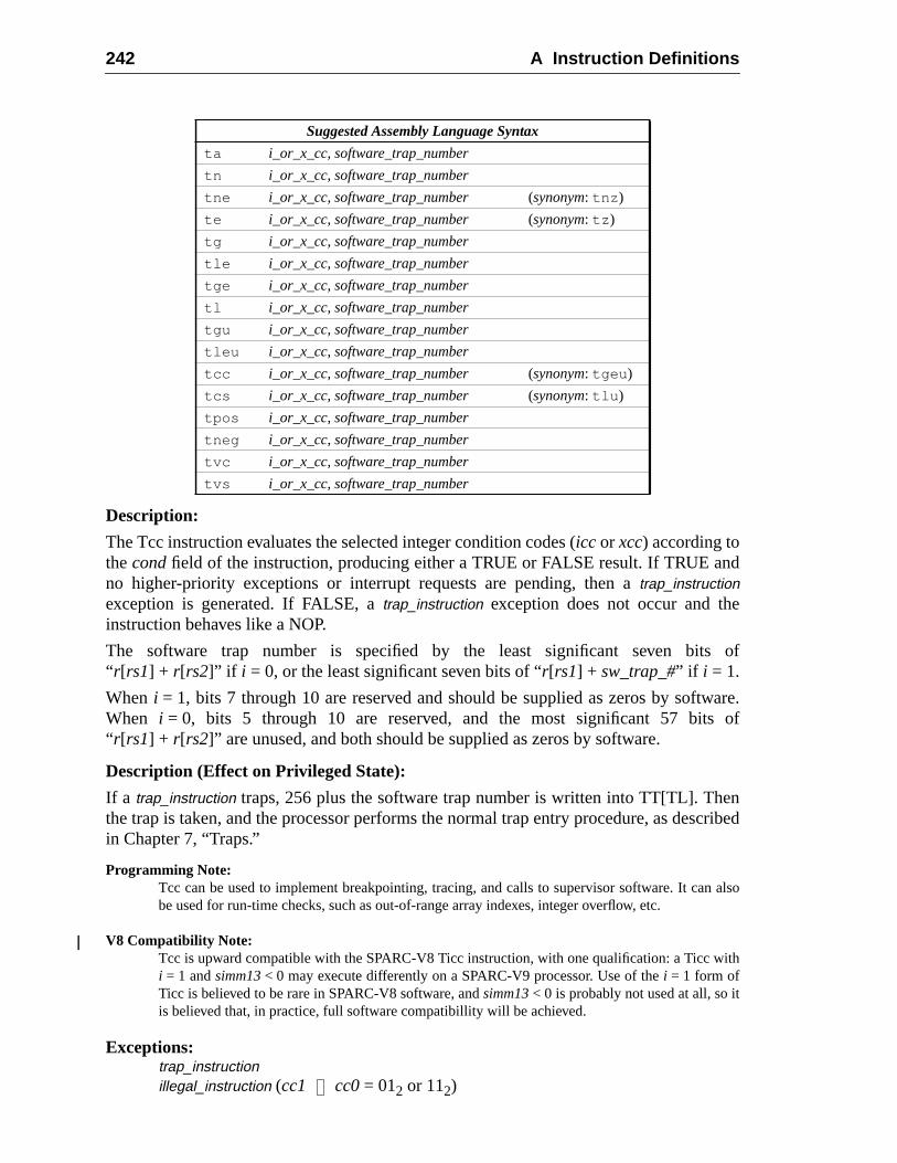
242 A Instruction Definitions
nd
e
of
ware.of
encribed
n also
ith
Description:
The Tcc instruction evaluates the selected integer condition codes (icc or xcc) according tothecondfield of the instruction, producing either a TRUE or FALSE result. If TRUE ano higher-priority exceptions or interrupt requests are pending, then atrap_instructionexception is generated. If FALSE, atrap_instruction exception does not occur and thinstruction behaves like a NOP.
The software trap number is specified by the least significant seven bits“ r[rs1] + r[rs2]” if i = 0, or the least significant seven bits of “r[rs1] + sw_trap_#” if i = 1.
When i = 1, bits 7 through 10 are reserved and should be supplied as zeros by softWhen i = 0, bits 5 through 10 are reserved, and the most significant 57 bits“ r[rs1] + r[rs2]” are unused, and both should be supplied as zeros by software.
Description (Effect on Privileged State):
If a trap_instruction traps, 256 plus the software trap number is written into TT[TL]. Ththe trap is taken, and the processor performs the normal trap entry procedure, as desin Chapter 7, “Traps.”
Programming Note:Tcc can be used to implement breakpointing, tracing, and calls to supervisor software. It cabe used for run-time checks, such as out-of-range array indexes, integer overflow, etc.
V8 Compatibility Note:Tcc is upward compatible with the SPARC-V8 Ticc instruction, with one qualification: a Ticc wi = 1 andsimm13< 0 may execute differently on a SPARC-V9 processor. Use of thei = 1 form ofTicc is believed to be rare in SPARC-V8 software, andsimm13< 0 is probably not used at all, so itis believed that, in practice, full software compatibillity will be achieved.
Exceptions:trap_instructionillegal_instruction (cc1 cc0= 012 or 112)
Suggested Assembly Language Syntax
ta i_or_x_cc, software_trap_number
tn i_or_x_cc, software_trap_number
tne i_or_x_cc, software_trap_number (synonym: tnz )
te i_or_x_cc, software_trap_number (synonym: tz )
tg i_or_x_cc, software_trap_number
tle i_or_x_cc, software_trap_number
tge i_or_x_cc, software_trap_number
tl i_or_x_cc, software_trap_number
tgu i_or_x_cc, software_trap_number
tleu i_or_x_cc, software_trap_number
tcc i_or_x_cc, software_trap_number (synonym: tgeu )
tcs i_or_x_cc, software_trap_number (synonym: tlu )
tpos i_or_x_cc, software_trap_number
tneg i_or_x_cc, software_trap_number
tvc i_or_x_cc, software_trap_number
tvs i_or_x_cc, software_trap_number
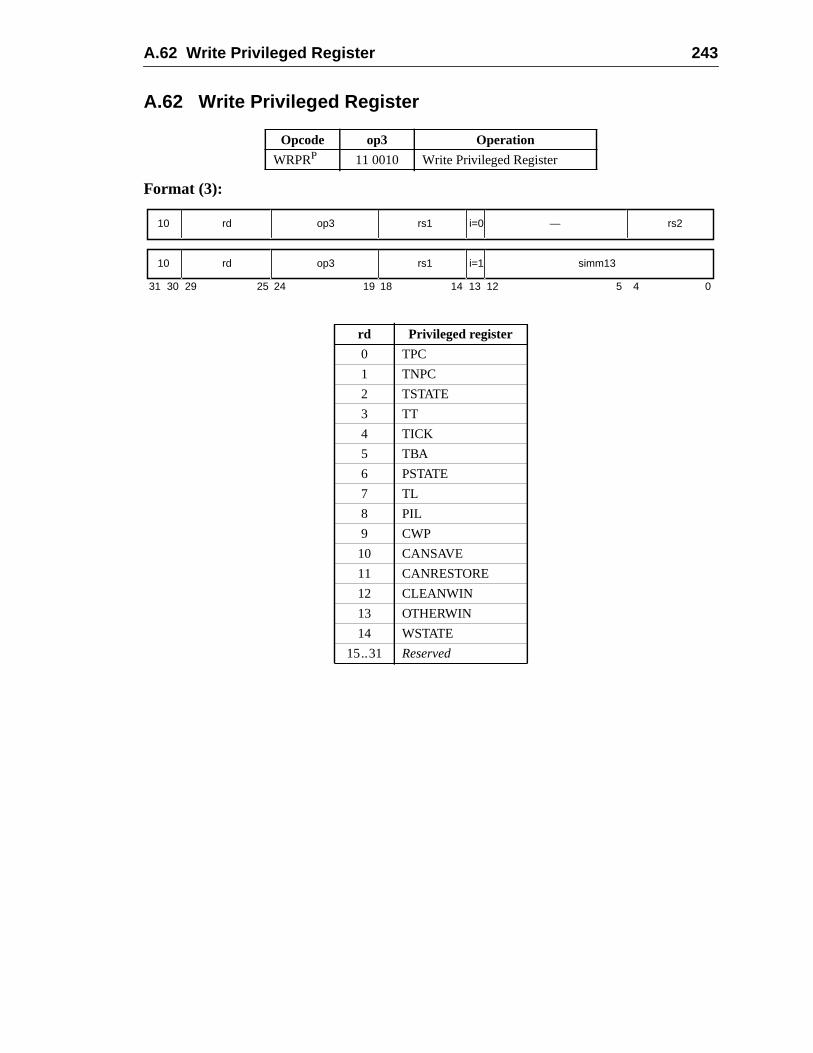
A.62 Write Privileged Register 243
A.62 Write Privileged Register
Format (3):
Opcode op3 Operation
WRPRP 11 0010 Write Privileged Register
rd Privileged register
0 TPC
1 TNPC
2 TSTATE
3 TT
4 TICK
5 TBA
6 PSTATE
7 TL
8 PIL
9 CWP
10 CANSAVE
11 CANRESTORE
12 CLEANWIN
13 OTHERWIN
14 WSTATE
15..31 Reserved
31 24 02530 29 19 18
rd10 op3 —
14 13 12 5 4
rs1 rs2i=0
rd10 op3 rs1 simm13i=1
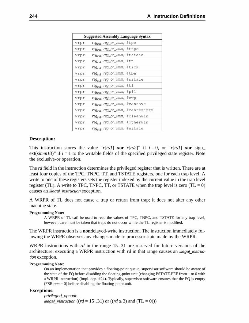
244 A Instruction Definitions
ote
re atel. A
level0)
ther
vel,
l-PR.
the
are ofwithmpty
Description:
This instruction stores the value “r[rs1] xor r[rs2]” if i = 0, or “r[rs1] xor sign_ext(simm13)” if i = 1 to the writable fields of the specified privileged state register. Nthe exclusive-or operation.
Therd field in the instruction determines the privileged register that is written. There aleast four copies of the TPC, TNPC, TT, and TSTATE registers, one for each trap levwrite to one of these registers sets the register indexed by the current value in the trapregister (TL). A write to TPC, TNPC, TT, or TSTATE when the trap level is zero (TL =causes anillegal_instruction exception.
A WRPR of TL does not cause a trap or return from trap; it does not alter any omachine state.Programming Note:
A WRPR of TL can be used to read the values of TPC, TNPC, and TSTATE for any trap lehowever, care must be taken that traps do not occur while the TL register is modified.
The WRPR instruction is anondelayed-write instruction. The instruction immediately folowing the WRPR observes any changes made to processor state made by the WR
WRPR instructions withrd in the range 15..31 are reserved for future versions ofarchitecture; executing a WRPR instruction withrd in that range causes anillegal_instruc-tion exception.Programming Note:
On an implementation that provides a floating-point queue, supervisor software should be awthe state of the FQ before disabling the floating-point unit (changing PSTATE.PEF from 1 to 0a WRPR instruction) (impl. dep. #24). Typically, supervisor software ensures that the FQ is e(FSR.qne= 0) before disabling the floating-point unit.
Exceptions:privileged_opcodeillegal_instruction ((rd = 15..31) or ((rd ≤ 3) and (TL = 0)))
Suggested Assembly Language Syntax
wrpr regrs1, reg_or_imm, %tpc
wrpr regrs1, reg_or_imm, %tnpc
wrpr regrs1, reg_or_imm, %tstate
wrpr regrs1, reg_or_imm, %tt
wrpr regrs1, reg_or_imm, %tick
wrpr regrs1, reg_or_imm, %tba
wrpr regrs1, reg_or_imm, %pstate
wrpr regrs1, reg_or_imm, %tl
wrpr regrs1, reg_or_imm, %pil
wrpr regrs1, reg_or_imm, %cwp
wrpr regrs1, reg_or_imm, %cansave
wrpr regrs1, reg_or_imm, %canrestore
wrpr regrs1, reg_or_imm, %cleanwin
wrpr regrs1, reg_or_imm, %otherwin
wrpr regrs1, reg_or_imm, %wstate
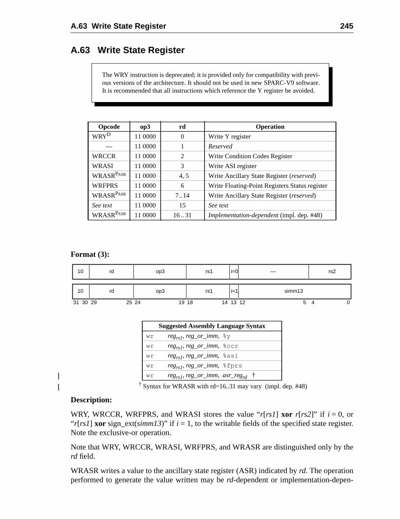
A.63 Write State Register 245
er.
the
-
A.63 Write State Register
Format (3):
† Syntax for WRASR with rd=16..31 may vary (impl. dep. #48)
Description:
WRY, WRCCR, WRFPRS, and WRASI stores the value “r[rs1] xor r[rs2]” if i = 0, or“ r[rs1] xor sign_ext(simm13)” if i = 1, to the writable fields of the specified state registNote the exclusive-or operation.
Note that WRY, WRCCR, WRASI, WRFPRS, and WRASR are distinguished only byrd field.
WRASR writes a value to the ancillary state register (ASR) indicated byrd. The operationperformed to generate the value written may berd-dependent or implementation-depen
Opcode op3 rd Operation
WRYD 11 0000 0 Write Y register
— 11 0000 1 Reserved
WRCCR 11 0000 2 Write Condition Codes Register
WRASI 11 0000 3 Write ASI register
WRASRPASR 11 0000 4, 5 Write Ancillary State Register (reserved)
WRFPRS 11 0000 6 Write Floating-Point Registers Status register
WRASRPASR 11 0000 7..14 Write Ancillary State Register (reserved)
See text 11 0000 15 See text
WRASRPASR 11 0000 16.. 31 Implementation-dependent (impl. dep. #48)
Suggested Assembly Language Syntax
wr regrs1, reg_or_imm, %y
wr regrs1, reg_or_imm, %ccr
wr regrs1, reg_or_imm, %asi
wr regrs1, reg_or_imm, %fprs
wr regrs1, reg_or_imm, asr_regrd †
The WRY instruction is deprecated; it is provided only for compatibility with previ-ous versions of the architecture. It should not be used in new SPARC-V9 software.It is recommended that all instructions which reference the Y register be avoided.
31 24 02530 29 19 18
rd10 op3 —
14 13 12 5 4
rs1 rs2i=0
rd10 op3 rs1 simm13i=1
246 A Instruction Definitions
ding
SI
the
trap-evi-gis-
9,
otdep.h
dent (see below). A WRASR instruction is indicated byop= 216, rd = 4, 5, or≥ 7 andop3= 3016.
An instruction withop= 216, op3= 3016, rd = 15, rs1 = 0, andi = 1 is defined as a SIRinstruction. See A.50, “Software-Initiated Reset.” Whenop= 216, op3= 3016, andrd = 15,if either rs1≠0 or i ≠1, then anillegal_instruction exception shall be generated.
IMPL. DEP. #48: WRASR instructions with rd in the range 16..31 are available for implementation-dependent uses (impl. dep. #8). For a WRASR instruction with rd in the range 16..31, the follow-ing are implementation-dependent: the interpretation of bits 18:0 in the instruction, the opera-tion(s) performed (for example, XOR) to generate the value written to the ASR, whether theinstruction is privileged (impl. dep. #9), and whether the instruction causes an illegal_instructionexception.
See I.1.1, “Read/Write Ancillary State Registers (ASRs),” for a discussion of extenthe SPARC-V9 instruction set using read/write ASR instructions.
The WRY, WRCCR, WRFPRS, and WRASI instructions arenot delayed-write instruc-tions. The instruction immediately following a WRY, WRCCR, WRFPRS, or WRAobserves the new value of the Y, CCR, FPRS, or ASI register.
WRFPRS waits for any pending floating-point operations to complete before writingFPRS register.
Implementation Note:Ancillary state registers may include (for example) timer, counter, diagnostic, self-test, andcontrol registers. SeeImplementation Characteristics of Current SPARC-V9-based Products, Rsion 9.x, a document available from SPARC International, for information on ancillary state reters provided by specific implementations.
V8 Compatibility Note:The SPARC-V8 WRIER, WRPSR, WRWIM, and WRTBR instructions do not exist in SPARC-Vsince the IER, PSR, TBR, and WIM registers do not exist in SPARC-V9.
Exceptions:privileged_opcode (WRASR only; implementation-dependent (impl. dep. #48))illegal_instruction (WRASR with rd = 16..31 and the implementation does n
define the instruction as an extension; implementation-dependent (impl.#48), or WRASR withrd equal to 1, 4, 5, or in the range 7..14), WRASR witrd equal to 15 andrs1≠0 or i ≠1
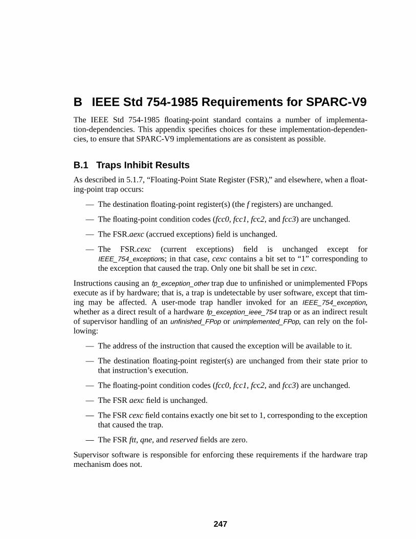
nta-nden-
float-
or
psat tim-
.
r to
tion
e trap
B IEEE Std 754-1985 Requirements for SPARC-V9The IEEE Std 754-1985 floating-point standard contains a number of implemetion-dependencies. This appendix specifies choices for these implementation-depecies, to ensure that SPARC-V9 implementations are as consistent as possible.
B.1 Traps Inhibit ResultsAs described in 5.1.7, “Floating-Point State Register (FSR),” and elsewhere, when aing-point trap occurs:
— The destination floating-point register(s) (thef registers) are unchanged.
— The floating-point condition codes (fcc0, fcc1, fcc2, andfcc3) are unchanged.
— The FSR.aexc (accrued exceptions) field is unchanged.
— The FSR.cexc (current exceptions) field is unchanged except fIEEE_754_exceptions; in that case,cexccontains a bit set to “1” corresponding tothe exception that caused the trap. Only one bit shall be set incexc.
Instructions causing anfp_exception_other trap due to unfinished or unimplemented FPoexecute as if by hardware; that is, a trap is undetectable by user software, except thing may be affected. A user-mode trap handler invoked for anIEEE_754_exception,whether as a direct result of a hardwarefp_exception_ieee_754 trap or as an indirect resultof supervisor handling of anunfinished_FPop or unimplemented_FPop, can rely on the fol-lowing:
— The address of the instruction that caused the exception will be available to it
— The destination floating-point register(s) are unchanged from their state priothat instruction’s execution.
— The floating-point condition codes (fcc0, fcc1, fcc2, andfcc3) are unchanged.
— The FSRaexc field is unchanged.
— The FSRcexcfield contains exactly one bit set to 1, corresponding to the excepthat caused the trap.
— The FSRftt, qne, andreserved fields are zero.
Supervisor software is responsible for enforcing these requirements if the hardwarmechanism does not.
247
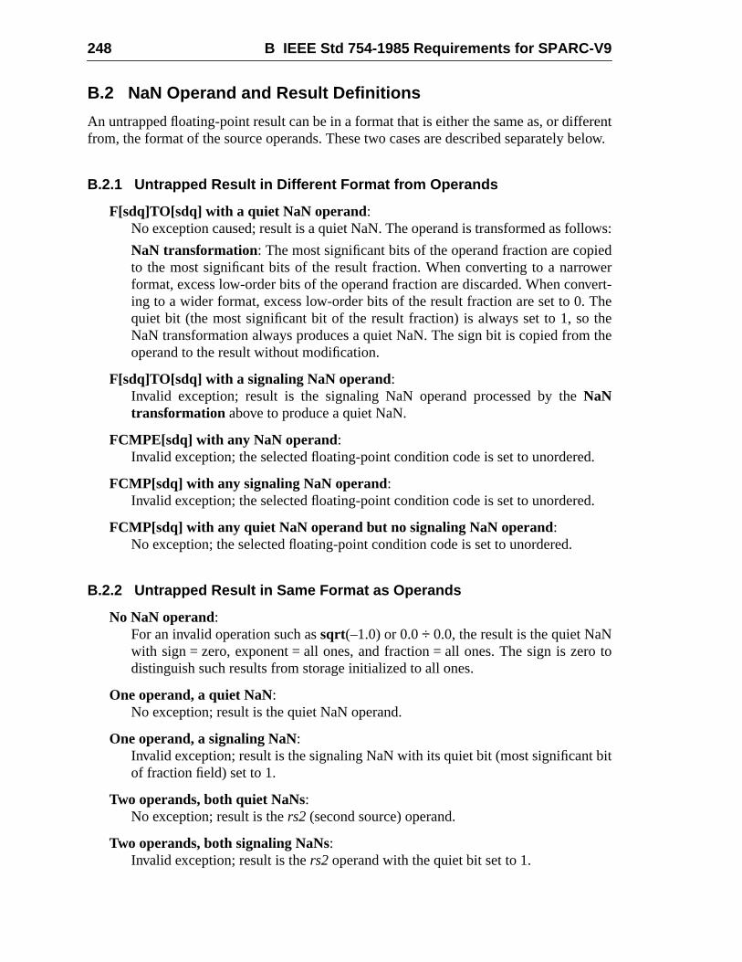
248 B IEEE Std 754-1985 Requirements for SPARC-V9
erent below.
lows:
edwervert-Thethethe
d.
d.
o to
bit
B.2 NaN Operand and Result Definitions
An untrapped floating-point result can be in a format that is either the same as, or difffrom, the format of the source operands. These two cases are described separately
B.2.1 Untrapped Result in Different Format from Operands
F[sdq]TO[sdq] with a quiet NaN operand:No exception caused; result is a quiet NaN. The operand is transformed as fol
NaN transformation: The most significant bits of the operand fraction are copito the most significant bits of the result fraction. When converting to a narroformat, excess low-order bits of the operand fraction are discarded. When coning to a wider format, excess low-order bits of the result fraction are set to 0.quiet bit (the most significant bit of the result fraction) is always set to 1, soNaN transformation always produces a quiet NaN. The sign bit is copied fromoperand to the result without modification.
F[sdq]TO[sdq] with a signaling NaN operand:Invalid exception; result is the signaling NaN operand processed by theNaNtransformation above to produce a quiet NaN.
FCMPE[sdq] with any NaN operand:Invalid exception; the selected floating-point condition code is set to unordere
FCMP[sdq] with any signaling NaN operand:Invalid exception; the selected floating-point condition code is set to unordere
FCMP[sdq] with any quiet NaN operand but no signaling NaN operand:No exception; the selected floating-point condition code is set to unordered.
B.2.2 Untrapped Result in Same Format as Operands
No NaN operand:For an invalid operation such assqrt(–1.0) or 0.0÷ 0.0, the result is the quiet NaNwith sign = zero, exponent = all ones, and fraction = all ones. The sign is zerdistinguish such results from storage initialized to all ones.
One operand, a quiet NaN:No exception; result is the quiet NaN operand.
One operand, a signaling NaN:Invalid exception; result is the signaling NaN with its quiet bit (most significantof fraction field) set to 1.
Two operands, both quiet NaNs:No exception; result is thers2 (second source) operand.
Two operands, both signaling NaNs:Invalid exception; result is thers2 operand with the quiet bit set to 1.
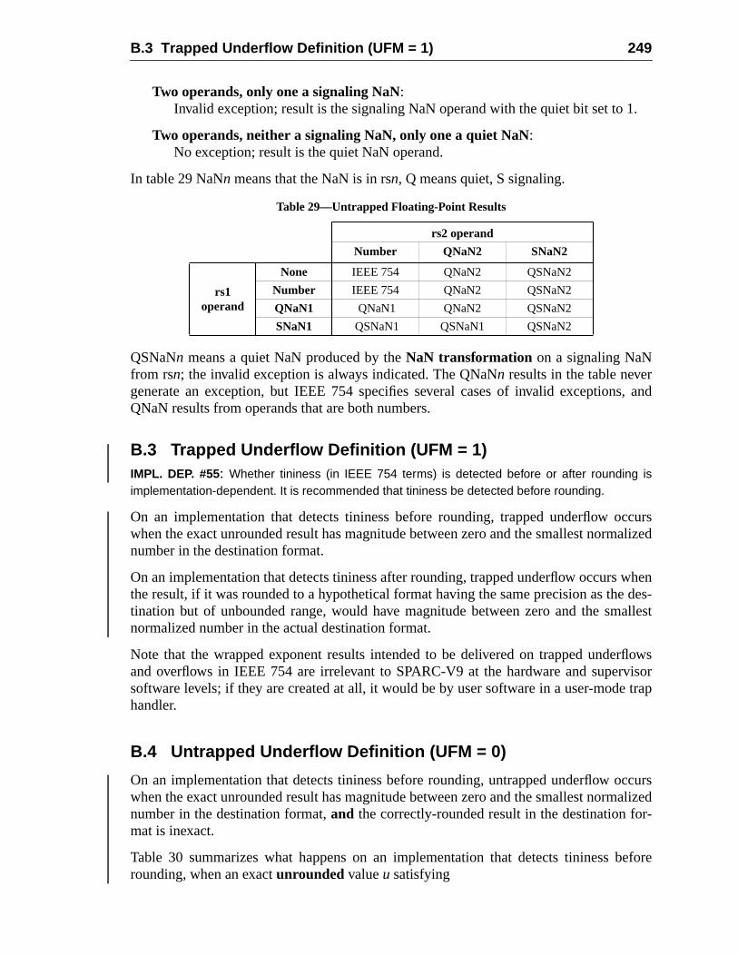
B.3 Trapped Underflow Definition (UFM = 1) 249
1.
s, and
ccursalized
whendes-allest
rflowsvisortrap
ccursalized
r-
before
Two operands, only one a signaling NaN:Invalid exception; result is the signaling NaN operand with the quiet bit set to
Two operands, neither a signaling NaN, only one a quiet NaN:No exception; result is the quiet NaN operand.
In table 29 NaNn means that the NaN is in rsn, Q means quiet, S signaling.
QSNaNn means a quiet NaN produced by theNaN transformation on a signaling NaNfrom rsn; the invalid exception is always indicated. The QNaNn results in the table nevergenerate an exception, but IEEE 754 specifies several cases of invalid exceptionQNaN results from operands that are both numbers.
B.3 Trapped Underflow Definition (UFM = 1)IMPL. DEP. #55: Whether tininess (in IEEE 754 terms) is detected before or after rounding isimplementation-dependent. It is recommended that tininess be detected before rounding.
On an implementation that detects tininess before rounding, trapped underflow owhen the exact unrounded result has magnitude between zero and the smallest normnumber in the destination format.
On an implementation that detects tininess after rounding, trapped underflow occursthe result, if it was rounded to a hypothetical format having the same precision as thetination but of unbounded range, would have magnitude between zero and the smnormalized number in the actual destination format.
Note that the wrapped exponent results intended to be delivered on trapped undeand overflows in IEEE 754 are irrelevant to SPARC-V9 at the hardware and supersoftware levels; if they are created at all, it would be by user software in a user-modehandler.
B.4 Untrapped Underflow Definition (UFM = 0)
On an implementation that detects tininess before rounding, untrapped underflow owhen the exact unrounded result has magnitude between zero and the smallest normnumber in the destination format,and the correctly-rounded result in the destination fomat is inexact.
Table 30 summarizes what happens on an implementation that detects tininessrounding, when an exactunrounded valueu satisfying
Table 29—Untrapped Floating-Point Results
rs2 operand
Number QNaN2 SNaN2
rs1operand
None IEEE 754 QNaN2 QSNaN2
Number IEEE 754 QNaN2 QSNaN2
QNaN1 QNaN1 QNaN2 QSNaN2
SNaN1 QSNaN1 QSNaN1 QSNaN2
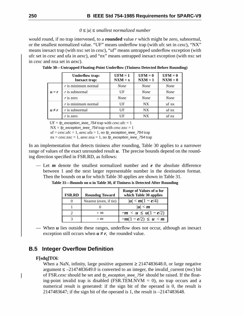
250 B IEEE Std 754-1985 Requirements for SPARC-V9
,
het
rowerd-
rmat.
xact
e
alt is
0 ≤ |u| ≤ smallest normalized number
would round, if no trap intervened, to arounded valuer which might be zero, subnormalor the smallest normalized value. “UF” means underflow trap (with ufc set incexc), “NX”means inexact trap (with nxc set incexc), “uf” means untrapped underflow exception (witufc set incexcand ufa inaexc), and “nx” means untrapped inexact exception (with nxc sin cexc and nxa set inaexc).
UF =fp_exception_ieee_754 trap withcexc.ufc = 1NX = fp_exception_ieee_754 trap withcexc.nxc = 1uf = cexc.ufc = 1,aexc.ufa = 1, nofp_exception_ieee_754 trapnx = cexc.nxc = 1,aexc.nxa = 1, nofp_exception_ieee_754 trap
In an implementation that detects tininess after rounding, Table 30 applies to a narrange of values of the exact unrounded resultu. The precise bounds depend on the rouning direction specified in FSR.RD, as follows:
— Let m denote the smallest normalized number ande the absolute differencebetween 1 and the next larger representable number in the destination foThen the bounds onu for which Table 30 applies are shown in Table 31.
— Whenu lies outside these ranges, underflow does not occur, although an ineexception still occurs whenu ≠ r, the rounded value.
B.5 Integer Overflow Definition
F[sdq]TOi :When a NaN, infinity, large positive argument≥ 2147483648.0, or large negativargument≤ –2147483649.0 is converted to an integer, the invalid_current (nvc) bitof FSR.cexcshould be set andfp_exception_ieee_754 should be raised. If the float-ing-point invalid trap is disabled (FSR.TEM.NVM = 0), no trap occurs andnumerical result is generated: if the sign bit of the operand is 0, the resu2147483647; if the sign bit of the operand is 1, the result is –2147483648.
Table 30—Untrapped Floating-Point Underflow (Tininess Detected Before Rounding)
Underflow trap:Inexact trap:
UFM = 1NXM = x
UFM = 0NXM = 1
UFM = 0NXM = 0
u = r
r is minimum normal None None None
r is subnormal UF None None
r is zero None None None
u ≠ r
r is minimum normal UF NX uf nx
r is subnormal UF NX uf nx
r is zero UF NX uf nx
Table 31—Bounds on u in Table 30, if Tininess is Detected After Rounding
FSR.RD Roundng TowardRange of Values of u forwhich Table 30 applies
0 Nearest (even, if tie) |u| < m(1 − e/4)1 0 |u| < m2 + ∞ −m < u ≤ u(1 − e/2)3 − ∞ −m(1 − e/2) ≤ u < m
B.6 Floating-Point Nonstandard Mode 251
a
Std. dep.
F[sdq]TOx:When a NaN, infinity, large positive argument≥ 263, or large negative argument≤–(263 + 1), is converted to an extended integer, the invalid_current (nvc) bit ofFSR.cexcshould be set andfp_exception_ieee_754 should be raised. If the float-ing-point invalid trap is disabled (FSR.TEM.NVM = 0), no trap occurs andnumerical result is generated: if the sign bit of the operand is 0, the result is 263 – 1;if the sign bit of the operand is 1, the result is –263.
B.6 Floating-Point Nonstandard Mode
SPARC-V9 implementations are permitted but not encouraged to deviate from IEEE754-1985 requirements when the nonstandard mode (NS) bit of the FSR is set (impl#18).
252 B IEEE Std 754-1985 Requirements for SPARC-V9
C-V9-
5.
tntional
orribe
t totrap.
e, or
pli-
se ele-n to
enta-ARC-
ARC-dwareexecu-d for
C SPARC-V9 Implementation DependenciesThis appendix provides a summary of all implementation dependencies in the SPARstandard. The notation “IMPL. DEP. #nn:” is used to identify the definition of an implementation dependency; the notation “(impl. dep. #nn)” is used to identify a reference to animplementation dependency. The numbernn provides an index into table 32 on page 25
SPARC International maintains a document,Implementation Characteristics of CurrenSPARC-V9-based Products, Revision 9.x, which describes the implementation-dependedesign features of SPARC-V9-compliant implementations. Contact SPARC Internatfor this document at
SPARC International535 Middlefield Rd, Suite 210
Menlo Park, CA 94025(415) 321-8692
C.1 Definition of an Implementation Dependency
The SPARC-V9 architecture is amodel that specifies unambiguously the behaviobserved bysoftware on SPARC-V9 systems. Therefore, it does not necessarily descthe operation of thehardware of any actual implementation.
An implementation isnot required to execute every instruction in hardware. An attempexecute a SPARC-V9 instruction that is not implemented in hardware generates aWhether an instruction is implemented directly by hardware, simulated by softwaremulated by firmware is implementation-dependent (impl. dep. #1).
The two levels of SPARC-V9 compliance are described in 1.2.6, “SPARC-V9 Comance.”
Some elements of the architecture are defined to be implementation-dependent. Thements include certain registers and operations that may vary from implementatioimplementation, and are explicitly identified as such in this appendix.
Implementation elements (such as instructions or registers) that appear in an implemtion but are not defined in this document (or its updates) are not considered to be SPV9 elements of that implementation.
C.2 Hardware Characteristics
Hardware characteristics that do not affect the behavior observed by software on SPV9 systems are not considered architectural implementation dependencies. A harcharacteristic may be relevant to the user system design (for example, the speed oftion of an instruction) or may be transparent to the user (for example, the method use
253
254 C SPARC-V9 Implementation Dependencies
esign
ing a
brevi-
asso-ber
asso-ned
ossi-eat-or a
leftple-ntation
cture,ach isddressxcep-
achieving cache consistency). The SPARC International document,Implementation Char-acteristics of Current SPARC-V9-based Products, Revision 9.x, provides a useful list ofthese hardware characteristics, along with the list of implementation-dependent dfeatures of SPARC-V9-compliant implementations.
In general, hardware characteristics deal with
— Instruction execution speed
— Whether instructions are implemented in hardware
— The nature and degree of concurrency of the various hardware units comprisSPARC-V9 implementation.
C.3 Implementation Dependency Categories
Many of the implementation dependencies can be grouped into four categories, abated by their first letters throughout this appendix:
Value (v):The semantics of an architectural feature are well-defined, except that a valueciated with it may differ across implementations. A typical example is the numof implemented register windows (Implementation dependency #2).
Assigned Value (a):The semantics of an architectural feature are well-defined, except that a valueciated with it may differ across implementations and the actual value is assigby SPARC International. Typical examples are theimpl field of Version register(VER) (Implemententation dependency #13) and the FSR.ver field (Implementa-tion dependency #19).
Functional Choice (f):The SPARC-V9 architecture allows implementors to choose among several pble semantics related to an architectural function. A typical example is the trment of a catastrophic error exception, which may cause either a deferreddisrupting trap (Implementation dependency #31).
Total Unit (t) :The existence of the architectural unit or function is recognized, but details areto each implementation. Examples include the handling of I/O registers (Immentation dependency #7) and some alternate address spaces (Implemedependency #29).
C.4 List of Implementation Dependencies
Table 32 provides a complete list of the implementation dependencies in the architethe definition of each, and references to the page numbers in the standard where edefined or referenced. Most implementation dependencies occur because of the aspaces, I/O registers, registers (including ASRs), the type of trapping used for an e
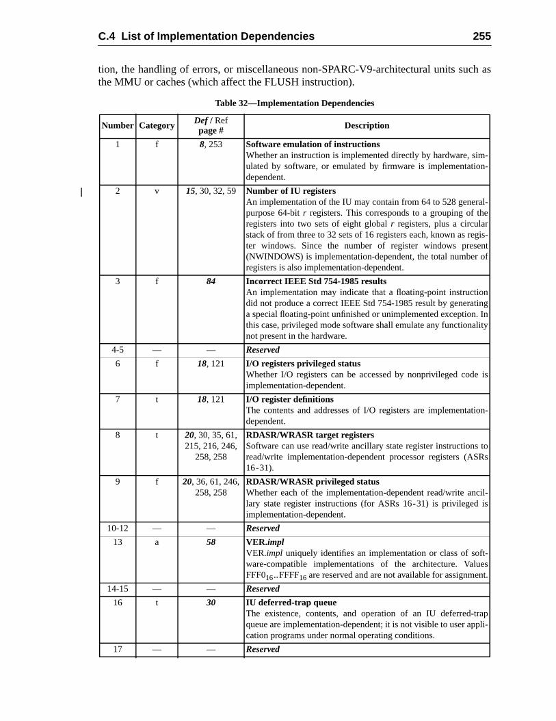
C.4 List of Implementation Dependencies 255
h as
--
l-e
is-ntf
ngInity
is
on-
toRs
il-s
-st.
apli-
tion, the handling of errors, or miscellaneous non-SPARC-V9-architectural units sucthe MMU or caches (which affect the FLUSH instruction).
Table 32—Implementation Dependencies
Number Category Def / Refpage # Description
1 f 8, 253 Software emulation of instructionsWhether an instruction is implemented directly by hardware, simulated by software, or emulated by firmware is implementationdependent.
2 v 15, 30, 32, 59 Number of IU registersAn implementation of the IU may contain from 64 to 528 generapurpose 64-bitr registers. This corresponds to a grouping of thregisters into two sets of eight globalr registers, plus a circularstack of from three to 32 sets of 16 registers each, known as regter windows. Since the number of register windows prese(NWINDOWS) is implementation-dependent, the total number oregisters is also implementation-dependent.
3 f 84 Incorrect IEEE Std 754-1985 resultsAn implementation may indicate that a floating-point instructiondid not produce a correct IEEE Std 754-1985 result by generatia special floating-point unfinished or unimplemented exception.this case, privileged mode software shall emulate any functionalnot present in the hardware.
4-5 — — Reserved
6 f 18, 121 I/O registers privileged statusWhether I/O registers can be accessed by nonprivileged codeimplementation-dependent.
7 t 18, 121 I/O register definitionsThe contents and addresses of I/O registers are implementatidependent.
8 t 20, 30, 35, 61,215, 216, 246,
258, 258
RDASR/WRASR target registersSoftware can use read/write ancillary state register instructionsread/write implementation-dependent processor registers (AS16-31).
9 f 20, 36, 61, 246,258, 258
RDASR/WRASR privileged statusWhether each of the implementation-dependent read/write anclary state register instructions (for ASRs 16-31) is privileged iimplementation-dependent.
10-12 — — Reserved
13 a 58 VER.implVER.impl uniquely identifies an implementation or class of software-compatible implementations of the architecture. ValueFFF016..FFFF16 are reserved and are not available for assignmen
14-15 — — Reserved
16 t 30 IU deferred-trap queueThe existence, contents, and operation of an IU deferred-trqueue are implementation-dependent; it is not visible to user appcation programs under normal operating conditions.
17 — — Reserved
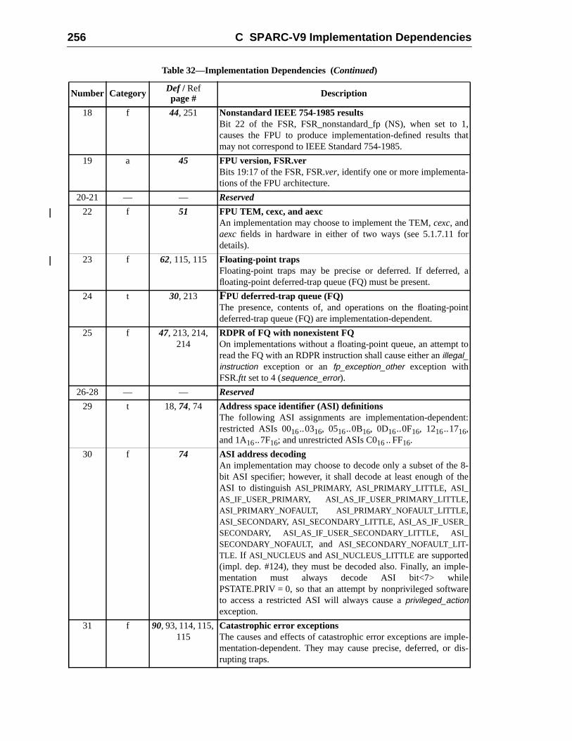
256 C SPARC-V9 Implementation Dependencies
1,hat
r
a
int
to
t:
8-e
e-
e
le-is-
18 f 44, 251 Nonstandard IEEE 754-1985 resultsBit 22 of the FSR, FSR_nonstandard_fp (NS), when set tocauses the FPU to produce implementation-defined results tmay not correspond to IEEE Standard 754-1985.
19 a 45 FPU version, FSR.verBits 19:17 of the FSR, FSR.ver, identify one or more implementa-tions of the FPU architecture.
20-21 — — Reserved
22 f 51 FPU TEM, cexc, and aexcAn implementation may choose to implement the TEM,cexc, andaexc fields in hardware in either of two ways (see 5.1.7.11 fodetails).
23 f 62, 115, 115 Floating-point trapsFloating-point traps may be precise or deferred. If deferred,floating-point deferred-trap queue (FQ) must be present.
24 t 30, 213 FPU deferred-trap queue (FQ)The presence, contents of, and operations on the floating-podeferred-trap queue (FQ) are implementation-dependent.
25 f 47, 213, 214,214
RDPR of FQ with nonexistent FQOn implementations without a floating-point queue, an attemptread the FQ with an RDPR instruction shall cause either anillegal_instruction exception or anfp_exception_other exception withFSR.ftt set to 4 (sequence_error).
26-28 — — Reserved
29 t 18,74, 74 Address space identifier (ASI) definitionsThe following ASI assignments are implementation-dependenrestricted ASIs 0016..0316, 0516..0B16, 0D16..0F16, 1216..1716,and 1A16..7F16; and unrestricted ASIs C016.. FF16.
30 f 74 ASI address decodingAn implementation may choose to decode only a subset of thebit ASI specifier; however, it shall decode at least enough of thASI to distinguishASI_PRIMARY, ASI_PRIMARY_LITTLE, ASI_AS_IF_USER_PRIMARY, ASI_AS_IF_USER_PRIMARY_LITTLE,ASI_PRIMARY_NOFAULT, ASI_PRIMARY_NOFAULT_LITTLE,ASI_SECONDARY, ASI_SECONDARY_LITTLE, ASI_AS_IF_USER_SECONDARY, ASI_AS_IF_USER_SECONDARY_LITTLE, ASI_SECONDARY_NOFAULT, and ASI_SECONDARY_NOFAULT_LIT-TLE. If ASI_NUCLEUSandASI_NUCLEUS_LITTLE are supported(impl. dep. #124), they must be decoded also. Finally, an implmentation must always decode ASI bit<7> whilePSTATE.PRIV = 0, so that an attempt by nonprivileged softwarto access a restricted ASI will always cause aprivileged_actionexception.
31 f 90, 93, 114, 115,115
Catastrophic error exceptionsThe causes and effects of catastrophic error exceptions are impmentation-dependent. They may cause precise, deferred, or drupting traps.
Table 32—Implementation Dependencies (Continued)
Number Category Def / Refpage # Description
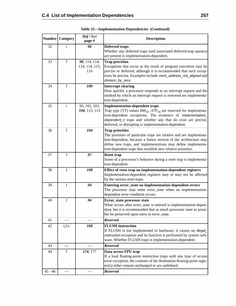
C.4 List of Implementation Dependencies 257
es)
beep-
theta-
e,
a-ay
ta-
ta-
ed
n-
en-ssi-
-
sis-
32 t 96 Deferred trapsWhether any deferred traps (and associated deferred-trap queuare present is implementation-dependent.
33 f 98, 114, 114,114, 114, 115,
116
Trap precisionExceptions that occur as the result of program execution mayprecise or deferred, although it is recommended that such exctions be precise. Examples includemem_address_not_aligned anddivision_by_zero.
34 f 100 Interrupt clearingHow quickly a processor responds to an interrupt request andmethod by which an interrupt request is removed are implemention-dependent.
35 t 93, 102, 103,104, 113, 115
Implementation-dependent trapsTrap type (TT) values 06016..07F16 are reserved for implementa-tion-dependent exceptions. The existence ofimplementation_dependent_n traps and whether any that do exist are precisdeferred, or disrupting is implementation-dependent.
36 f 104 Trap prioritiesThe priorities of particular traps are relative and are implementtion-dependent, because a future version of the architecture mdefine new traps, and implementations may define implemention-dependent traps that establish new relative priorities.
37 f 97 Reset trapSome of a processor’s behavior during a reset trap is implemention-dependent.
38 f 108 Effect of reset trap on implementation-dependent registersImplementation-dependent registers may or may not be affectby the various reset traps.
39 f 94 Entering error_state on implementation-dependent errorsThe processor may enter error_state when an implementatiodependent error condition occurs.
40 f 94 Error_state processor stateWhat occurs after error_state is entered is implementation-depdent, but it is recommended that as much processor state as poble be preserved upon entry to error_state.
41 — — Reserved
42 t,f,v 168 FLUSH instructionIf FLUSH is not implemented in hardware, it causes anillegal_instruction exception and its function is performed by system software. Whether FLUSH traps is implementation-dependent.
43 — — Reserved
44 f 174, 177 Data access FPU trapIf a load floating-point instruction traps with any type of acceserror exception, the contents of the destination floating-point regter(s) either remain unchanged or are undefined.
45 - 46 — — Reserved
Table 32—Implementation Dependencies (Continued)
Number Category Def / Refpage # Description
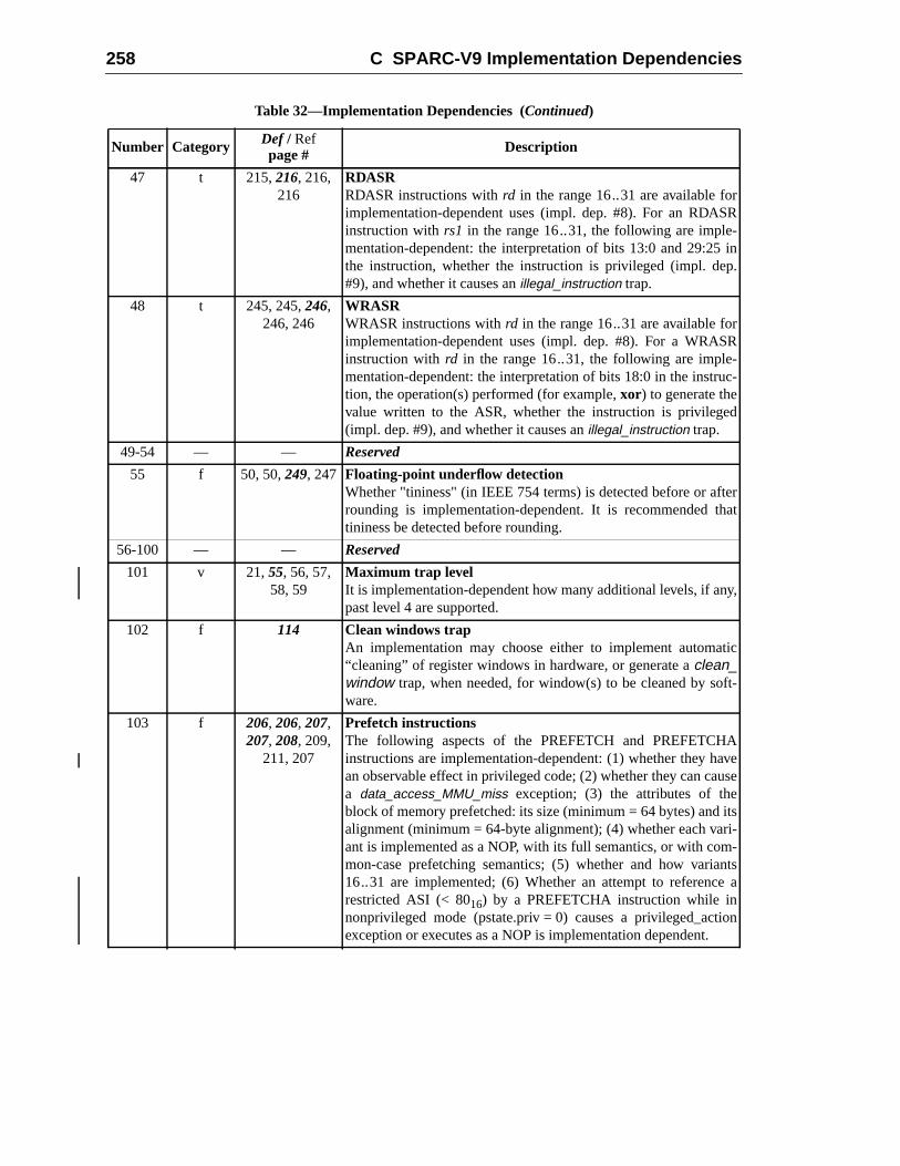
258 C SPARC-V9 Implementation Dependencies
R
in.
R
c-
erat
y,
ic
t-
vese
tsi--
ntsa
n
47 t 215,216, 216,216
RDASRRDASR instructions withrd in the range 16..31 are available forimplementation-dependent uses (impl. dep. #8). For an RDASinstruction withrs1 in the range 16..31, the following are imple-mentation-dependent: the interpretation of bits 13:0 and 29:25the instruction, whether the instruction is privileged (impl. dep#9), and whether it causes anillegal_instruction trap.
48 t 245, 245,246,246, 246
WRASRWRASR instructions withrd in the range 16..31 are available forimplementation-dependent uses (impl. dep. #8). For a WRASinstruction withrd in the range 16..31, the following are imple-mentation-dependent: the interpretation of bits 18:0 in the instrution, the operation(s) performed (for example,xor) to generate thevalue written to the ASR, whether the instruction is privileged(impl. dep. #9), and whether it causes anillegal_instruction trap.
49-54 — — Reserved
55 f 50, 50,249, 247 Floating-point underflow detectionWhether "tininess" (in IEEE 754 terms) is detected before or aftrounding is implementation-dependent. It is recommended thtininess be detected before rounding.
56-100 — — Reserved
101 v 21,55, 56, 57,58, 59
Maximum trap levelIt is implementation-dependent how many additional levels, if anpast level 4 are supported.
102 f 114 Clean windows trapAn implementation may choose either to implement automat“cleaning” of register windows in hardware, or generate aclean_window trap, when needed, for window(s) to be cleaned by sofware.
103 f 206, 206, 207,207, 208, 209,
211, 207
Prefetch instructionsThe following aspects of the PREFETCH and PREFETCHAinstructions are implementation-dependent: (1) whether they haan observable effect in privileged code; (2) whether they can caua data_access_MMU_miss exception; (3) the attributes of theblock of memory prefetched: its size (minimum = 64 bytes) and ialignment (minimum = 64-byte alignment); (4) whether each varant is implemented as a NOP, with its full semantics, or with common-case prefetching semantics; (5) whether and how varia16..31 are implemented; (6) Whether an attempt to referencerestricted ASI (< 8016) by a PREFETCHA instruction while innonprivileged mode (pstate.priv = 0) causes a privileged_actioexception or executes as a NOP is implementation dependent.
Table 32—Implementation Dependencies (Continued)
Number Category Def / Refpage # Description

C.4 List of Implementation Dependencies 259
e.
inhe-aveal
onteded,An
les
-udeir
ill
eill
d,
or
-d-
he
er
or
104 a 58 VER.manufVER.manufcontains a 16-bit semiconductor manufacturer codThis field is optional, and if not present reads as zero. VER.manufmay indicate the original supplier of a second-sourced chipcases involving mask-level second-sourcing. It is intended that tcontents of VER.manuftrack the JEDEC semiconductor manufacturer code as closely as possible. If the manufacturer does not ha JEDEC semiconductor manufacturer code, SPARC Internationwill assign a VER.manuf value.
105 f 52 TICK registerThe difference between the values read from the TICK registertwo reads should reflect the number of processor cycles execubetween the reads. If an accurate count cannot always be returnany inaccuracy should be small, bounded, and documented.implementation may implement fewer than 63 bits inTICK.counter; however, the counter as implemented must be abto count for at least 10 years without overflowing. Any upper bitnot implemented must read as zero.
106 f 84,171 IMPDEPn instructionsThe IMPDEP1 and IMPDEP2 instructions are completely implementation-dependent. Implementation-dependent aspects incltheir operation, the interpretation of bits 29:25 and 18:0 in theencodings, and which (if any) exceptions they may cause.
107 f 179, 179,181,181
Unimplemented LDD trapIt is implementation-dependent whether LDD and LDDA areimplemented in hardware. If not, an attempt to execute either wcause anunimplemented_LDD trap.
108 f 117,230, 231,233, 233
Unimplemented STD trapIt is implementation-dependent whether STD and STDA arimplemented in hardware. If not, an attempt to execute either wcause anunimplemented_STD trap.
109 f 115,174, 174,177
LDDF_mem_address_not_alignedLDDF and LDDFA require only word alignment. However, if theeffective address is word-aligned but not doubleword-aligneeither may cause anLDDF_mem_address_not_aligned trap, inwhich case the trap handler software shall emulate the LDDF (LDDFA) instruction and return.
110 f 116,227, 227,229, 229
STDF_mem_address_not_alignedSTDF and STDFA require only word alignment in memory. However, if the effective address is word-aligned but not doubleworaligned, either may cause anSTDF_mem_address_not_alignedtrap, in which case the trap handler software shall emulate tSTDF or STDFA instruction and return.
111 f 116,174, 174,177
LDQF_mem_address_not_alignedLDQF and LDQFA require only word alignment. However, if theeffective address is word-aligned but not quadword-aligned, eithmay cause anLDQF_mem_address_not_aligned trap, in whichcase the trap handler software shall emulate the LDQF (LDQFA) instruction and return.
Table 32—Implementation Dependencies (Continued)
Number Category Def / Refpage # Description
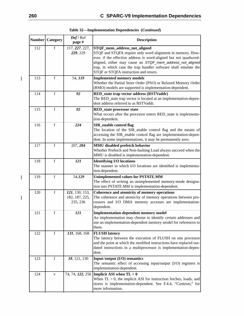
260 C SPARC-V9 Implementation Dependencies
-d-
he
er
n-
ta-
ofen-
he
-
-
ro-n-
ndto
ort-
n-
is
or
112 f 117,227, 227,229, 229
STQF_mem_address_not_alignedSTQF and STQFA require only word alignment in memory. However, if the effective address is word-aligned but not quadworaligned, either may cause anSTQF_mem_address_not_alignedtrap, in which case the trap handler software shall emulate tSTQF or STQFA instruction and return.
113 f 54,119 Implemented memory modelsWhether the Partial Store Order (PSO) or Relaxed Memory Ord(RMO) models are supported is implementation-dependent.
114 f 92 RED_state trap vector address (RSTVaddr)The RED_state trap vector is located at an implementation-depedent address referred to as RSTVaddr.
115 f 92 RED_state processor stateWhat occurs after the processor enters RED_state is implemention-dependent.
116 f 224 SIR_enable control flagThe location of the SIR_enable control flag and the meansaccessing the SIR_enable control flag are implementation-depdent. In some implementations, it may be permanently zero.
117 f 207,284 MMU disabled prefetch behaviorWhether Prefetch and Non-faulting Load always succeed when tMMU is disabled is implementation-dependent.
118 f 121 Identifying I/O locationsThe manner in which I/O locations are identified is implementation-dependent.
119 f 54,129 Unimplemented values for PSTATE.MMThe effect of writing an unimplemented memory-mode designation into PSTATE.MM is implementation-dependent.
120 f 121, 130, 153,182, 187, 225,
235, 236
Coherence and atomicity of memory operationsThe coherence and atomicity of memory operations between pcessors and I/O DMA memory accesses are implementatiodependent.
121 f 121 Implementation-dependent memory modelAn implementation may choose to identify certain addresses ause an implementation-dependent memory model for referencesthem.
122 f 131, 168, 168 FLUSH latencyThe latency between the execution of FLUSH on one processand the point at which the modified instructions have replaced oudated instructions in a multiprocessor is implementation-depedent.
123 f 18, 121, 130 Input/output (I/O) semanticsThe semantic effect of accessing input/output (I/O) registersimplementation-dependent.
124 v 74, 74,122, 256 Implicit ASI when TL > 0When TL > 0, the implicit ASI for instruction fetches, loads, andstores is implementation-dependent. See F.4.4, “Contexts,” fmore information.
Table 32—Implementation Dependencies (Continued)
Number Category Def / Refpage # Description
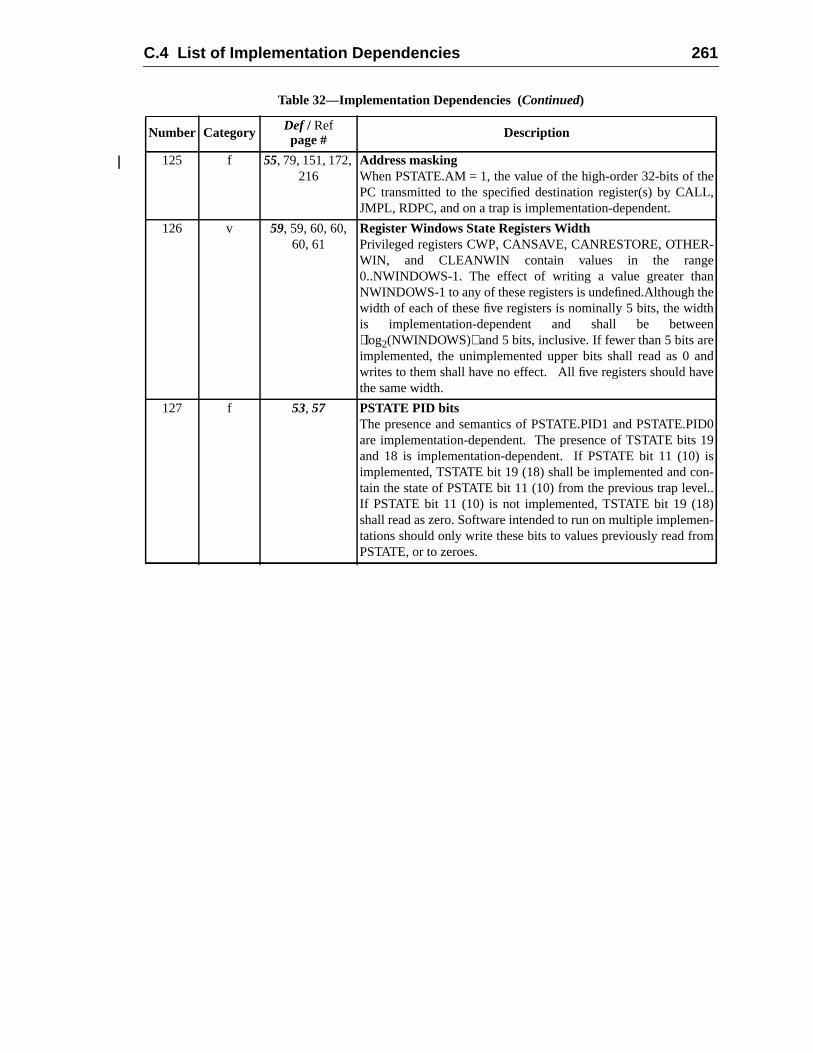
C.4 List of Implementation Dependencies 261
L,
-
ehn
nde
019s-
..
n-m
125 f 55, 79, 151, 172,216
Address maskingWhen PSTATE.AM = 1, the value of the high-order 32-bits of thePC transmitted to the specified destination register(s) by CALJMPL, RDPC, and on a trap is implementation-dependent.
126 v 59, 59, 60, 60,60, 61
Register Windows State Registers WidthPrivileged registers CWP, CANSAVE, CANRESTORE, OTHERWIN, and CLEANWIN contain values in the range0..NWINDOWS-1. The effect of writing a value greater thanNWINDOWS-1 to any of these registers is undefined.Although thwidth of each of these five registers is nominally 5 bits, the widtis implementation-dependent and shall be betweelog2(NWINDOWS) and 5 bits, inclusive. If fewer than 5 bits areimplemented, the unimplemented upper bits shall read as 0 awrites to them shall have no effect. All five registers should havthe same width.
127 f 53, 57 PSTATE PID bitsThe presence and semantics of PSTATE.PID1 and PSTATE.PIDare implementation-dependent. The presence of TSTATE bitsand 18 is implementation-dependent. If PSTATE bit 11 (10) iimplemented, TSTATE bit 19 (18) shall be implemented and contain the state of PSTATE bit 11 (10) from the previous trap levelIf PSTATE bit 11 (10) is not implemented, TSTATE bit 19 (18)shall read as zero. Software intended to run on multiple implemetations should only write these bits to values previously read froPSTATE, or to zeroes.
Table 32—Implementation Dependencies (Continued)
Number Category Def / Refpage # Description

262 C SPARC-V9 Implementation Dependencies
tionscrip-tion.iption
tion,ple-
-o real
nanspar-stem,oher-
es notistent.e thatanage
ertiesry is
essorsssor
hing iscon-
olu-
D Formal Specification of the Memory ModelsThis appendix provides a formal description of the SPARC-V9 processor’s interacwith memory. The formal description is more complete and more precise than the detion of Chapter 8, “Memory Models,” and therefore represents the definitive specificaImplementations must conform to this model, and programmers must use this descrto resolve any ambiguity.
This formal specification is not intended to be a description of an actual implementaonly to describe in a precise and rigorous fashion the behavior that any conforming immentation must provide.
D.1 Processors and Memory
The system model consists of a collection of processors, P0, P1,..Pn-1. Each processor executes its own instruction stream.1 Processors may share address space and access tmemory and I/O locations.
To improve performance, processors may interpose acacheor caches in the path betweethe processor and memory. For data and I/O references, caches are required to be trent. The memory model specifies the functional behavior of the entire memory subsywhich includes any form of caching. Implementations must use appropriate cache cency mechanisms to achieve this transparency.2
The SPARC-V9 memory model requires that all data references be consistent but dorequire that instruction references or input/output references be maintained consThe FLUSH instruction or an appropriate operating system call may be used to ensurinstruction and data spaces are consistent. Likewise, system software is needed to mthe consistency of I/O operations.
The memory model is a local property of a processor that determines the order propof memory references. The ordering properties have global implications when memoshared, since the memory model determines what data is visible to observing procand in what order. Moreover, the operative memory model of the observing proceaffects the apparent order of shared data reads and writes that it observes.
1. Processors are equivalent to their software abstraction, processes, provided that context switcproperly performed. See Appendix J, “Programming With the Memory Models,” for an example oftext switch code.
2. Philip Bitar and Alvin M. Despain, “Multiprocessor Cache Synchronization: Issues, Innovations, Evtion,” Proc. 13th Annual International Symposium on Computer Architecture, Computer ArchitectureNews 14:2, June 1986, pp.424-433.
263
264 D Formal Specification of the Memory Models
ts onorder-ted.
Anitrary
ecution
ialanticution
.
de-e con-
er holdsthat
andr con-citlyThemory
TheartialfinedI/O
ifieddif-ingle
dis-
els,”
aran-
D.2 An Overview of the Memory Model Specification
The underlying goal of the memory model is to place the weakest possible constrainthe processor implementations and to provide a precise specification of the possibleings of memory operations so that shared-memory multiprocessors can be construc
An execution traceis a sequence of instructions with a specified initial instruction.execution trace constitutes one possible execution of a program and may involve arbreorderings and parallel execution of instructions. Aself-consistentexecution trace is onethat generates precisely the same results as those produced by a program order extrace.
A program order execution traceis an execution trace that begins with a specified initinstruction and executes one instruction at a time in such a fashion that all the semeffects of each instruction take effect before the next instruction is begun. The exectrace this process generates is defined to beprogram order.
A program is defined by the collection of all possible program order execution traces
Dependence orderis a partial order on the instructions in an execution trace that is aquate to ensure that the execution trace is self-consistent. Dependence order can bstructed using conventional data dependence analysis techniques. Dependence ordonly between instructions in the instruction trace of a single processor; instructionsare part of execution traces on different processors are never dependence-ordered.
Memory order is a total order on the memory reference instructions (loads, stores,atomic load/stores) which satisfies the dependence order and, possibly, other ordestraints such as those introduced implicitly by the choice of memory model or expliby the appearance of memory barrier (MEMBAR) instructions in the execution trace.existence of a global memory order on the performance of all stores implies that meaccess is write-atomic.3
A memory model is a set of rules that constrain the order of memory references.SPARC-V9 architecture supports three memory models: total store order (TSO), pstore order (PSO), and relaxed memory order (RMO). The memory models are deonly for memory and not for I/O locations. See 8.2, “Memory, Real Memory, andLocations,” for more information.
The formal definition used in the SPARC-V8 specification4 remains valid for the defini-tion of PSO and TSO, except for the FLUSH instruction, which has been modslightly.5 The SPARC-V9 architecture introduces a new memory model, RMO, whichfers from TSO and PSO in that it allows load operations to be reordered as long as sthread programs remain self-consistent.
3. W.W. Collier, “Reasoning About Parallel Architectures”, Prentice-Hall, 1992 includes an excellentcussion of write-atomicity and related memory model topics.
4. Pradeep Sindhu, Jean-Marc Frailong, and Michel Ceklov. “Formal Specification of Memory ModXerox Palo Alto Research Center Report CSL-91-11, December 1991.
5. In SPARC-V8, a FLUSH instruction needs at least five instruction execution cycles before it is guteed to have local effects; in SPARC-V9 this five-cycle requirement has been removed.
D.3 Memory Transactions 265
. Theor ini-to all
tion.load
ified
then set
struc-e oper-
-e
tionAR
pro-
. Bothate
placeails is
deter-
D.3 Memory TransactionsD.3.1 Memory Transactions
A memory transaction is one of the following:
Store:A request by a processor to replace the value of a specified memory locationaddress and new value are bound to the store transaction when the processtiates the store transaction. A store is complete when the new value is visibleprocessors in the system.
Load:A request by a processor to retrieve the value of the specified memory locaThe address is bound to the load transaction when the processor initiates thetransaction. A load is complete when the value being returned cannot be modby a store made by another processor.
Atomic:A load/storepair with the guarantee that no other memory transaction will alterstate of the memory between the load and the store. The SPARC-V9 instructioincludes three atomic instructions: LDSTUB, SWAP and CAS.6 An atomic trans-action is considered to be both a load and a store.7
Flush:A request by a processor to force changes in the data space aliased to the intion space to become consistent. Flush transactions are considered to be storations for memory model purposes.
Memory transactions are referred to by capital letters:Xna, which denotes a specific memory transactionX by processorn to memory addressa. The processor index and thaddress are specified only if needed. The predicateS(X) is true if and only ifX has storesemantics. The predicateL(X) is true if and only ifX has load semantics.
MEMBAR instructions are not memory transactions; rather they convey order informaabove and beyond the implicit ordering implied by the memory model in use. MEMBinstructions are applied in program order.
D.3.2 Program Order
Theprogram order is a per-processor total order that denotes the sequence in whichcessorn logically executes instructions. The program order relation is denoted by<p such
6. There are three generic forms. CASA and CASXA reference 32-bit and 64-bit objects respectivelynormal and alternate ASI forms exist for LDSTUB and SWAP. CASA and CASXA only have alternforms, however, a CASA (CASXA) with ASI = ASI_PRIMARY{_LITTLE} is equivalent to CAS(CASX). Synthetic instructions for CAS and CASX are suggested in G.3, “Synthetic Instructions.”
7. Even though the store part of a CASA is conditional, it is assumed that the store will always takewhether it does or not in a particular implementation. Since the value stored when the condition fthe value already present, and since the CASA operation is atomic, no observing processor canmine whether the store occurred or not.
266 D Formal Specification of the Memory Models
one
with
nto a
ns-
hereeyondem-
V8
struc-maxi-gisters
:
ith the
pro-ondi-
rela-ree
ized orociatedam-
thatXn <p Yn is true if and only if the memory transactionXn is caused by an instructionthat is executed before the instruction that caused memory transactionYn.
Program order specifies a unique total order for all memory transactions initiated byprocessor.
Memory barrier (MEMBAR) instructions executed by the processor are orderedrespect to<p. The predicateM(X,Y)is true if and only ifX <p Yand there exists a MEM-BAR instruction that ordersX andY (that is, it appears in program order betweenX andY).MEMBAR instructions can be either ordering or sequencing and may be combined isingle instruction using a bit-encoded mask.8
Ordering MEMBAR instructions impose constraints on the order in which memory traactions are performed.
Sequencing MEMBARs introduce additional constraints that are required in cases wthe memory transaction has side-effects beyond storing data. Such side-effects are bthe scope of the memory model, which is limited to order and value semantics for mory.9
This definition of program order is equivalent to the definition given in the SPARC-memory model specification.
D.3.3 Dependence Order
Dependence order is a partial order that captures the constraints that hold between intions that access the same processor register or memory location. In order to allowmum concurrency in processor implementations, dependence order assumes that reare dynamically renamed to avoid false dependences arising from register reuse.
Two memory transactionX andY are dependence ordered, denoted byX <d Y, if and onlyif they are program ordered,X <p Y , and at least one of the following conditions is true
(1) The execution ofY is conditional onX, and S(Y) is true.
(2) Y reads a register that is written byX.
(3) X and Y access the same memory location andS(X) andL(Y) are both true.
The dependence order also holds between the memory transactions associated winstructions. It is important to remember that partial ordering is transitive.
Rule (1) includes all control dependences that arise from the dynamic execution ofgrams. In particular, a store or atomic memory transaction that is executed after a c
8. The Ordering MEMBAR instruction uses 4 bits of its argument to specify the existence of an ordertion depending on whetherX andYhave load or store semantics. The Sequencing MEMBAR uses thbits to specify completion conditions. The MEMBAR encoding is specified in A.32.
9. Sequencing constraints have other effects, such as controlling when a memory error is recognwhen an I/O access reaches global visibility. The need for sequencing constraints is always asswith I/O and kernel level programming and not usually with normal, user-level application progrming.
D.4 Specification of Relaxed Memory Order (RMO) 267
willLoadses nottion of
de anllg ancon-ondi-
loca-pairs,since
ding,d soence
ecifyepen-aints:r only
equire-
em-xecu-
long
tional branch will depend on the outcome of that branch instruction, which in turndepend on one or more memory transactions that precede the branch instruction.after an unresolved conditional branch may proceed, that is, a conditional branch dodependence order subsequent loads. Control dependences always order the initiasubsequent instructions to the performance of the preceding instructions.10
Rule (2) captures dependences arising from register use. It is not necessary to incluordering whenX reads a register that is later written byY, because register renaming wiallow out-of-order execution in this case. Register renaming is equivalent to havininfinite pool of registers and requiring all registers to be write-once. Observe that thedition code register is set by some arithmetic and logical instructions and used by ctional branch instructions thus introducing a dependence order.
Rule (3) captures ordering constraints resulting from memory accesses to the sametion and require that the dependence order reflect the program order for store-loadbut not for load-store or store-store pairs. A load may be executed speculatively,loads are side-effect free, provided that Rule (3) is eventually satisfied.
An actual processor implementation will maintain dependence order by score-boarhardware interlocks, data flow techniques, compiler directed code scheduling, anforth, or, simply, by sequential program execution. The means by which the dependorder is derived from a program is irrelevant to the memory model, which has to spwhich possible memory transaction sequences are legal for a given set of data ddences. Practical implementations will not necessarily use the minimal set of constradding unnecessary order relations from the program order to the dependence ordereduces the available concurrency, but does not impair correctness.
D.3.4 Memory Order
The sequence in which memory transactions are performed by the memory is calledmem-ory order, which is a total order on all memory transactions.
In general, the memory order cannot be knowna priori. Instead, the memory order isspecified as a set of constraints that are imposed on the memory transactions. The rment that memory transactionX must be performed before memory transactionY isdenoted byX <m Y.Any memory order that satisfies these constraints is legal. The mory subsystem may choose arbitrarily among legal memory orders, hence multiple etions of the same programs may result in different memory orders.
D.4 Specification of Relaxed Memory Order (RMO)
D.4.1 Value Atomicity
Memory transactions will atomically set or retrieve the value of a memory location asas the size of the value is less than or equal to eight bytes, the unit of coherency.
10. Self modifying code (use of FLUSH instructions) also causes control dependences.
268 D Formal Specification of the Memory Models
r that
MO
em-ts. Noemorytion
nsac-r may
ions.
is nec-
pectssor.
andthe
whichssuingffers,
D.4.2 Store Atomicity
All possible execution traces are consistent with the existence of a memory ordetotally orders all transactions including all store operations.
This does not imply that the memory order is observable. Nor does it imply that Rrequires any central serialization mechanism.
D.4.3 Atomic Memory Transactions
The atomic memory transactions SWAP, LDSTUB, and CAS are performed as one mory transaction that is both a load and a store with respect to memory order constrainother memory transaction can separate the load and store actions of an atomic mtransaction. The semantics of atomic instructions are defined in Appendix A, “InstrucDefinitions.”
D.4.4 Memory Order Constraints
A memory order is legal in RMO if and only if:
(1) X <d Y & L(X)⇒ X <m Y
(2) M(X,Y)⇒ X <m Y
(3) Xa <p Ya & S(Y)⇒ X <m Y
Rule (1) states that the RMO model will maintain dependence when the preceding tration is a load. Preceding stores may be delayed in the implementation, so their ordenot be preserved globally.
Rule (2) states that MEMBAR instructions order the performance of memory transact
Rule (3) states that stores to the same address are performed in program order. Thisessary for processor self-consistency
D.4.5 Value of Memory Transactions
The value of a loadYais the value of the most recent store that was performed with resto memory order or the value of the most recently initiated store by the same proceAssumingY is a load to memory locationa:
Value(La) = Value( Max<m { S | Sa <m La or Sa <p La } )
whereMax<m{..} selects the most recent element with respect to the memory orderwhereValue() yields the value of a particular memory transaction. This states thatvalue returned by a load is either the result of the most recent store to that addresshas been performed by any processor or which has been initiated by the processor ithe load. The distinction between local and remote stores permits use of store-buwhich are explicitly supported in all SPARC-V9 memory models.
D.5 Specification of Partial Store Order (PSO) 269
ire-pend-
rder islushxecu-
O)fol-
thed by
execu-by thetrans-r each
ssorsbserveyation,
f the
D.4.6 Termination of Memory Transactions
Any memory transaction will eventually be performed. This is formalized by the requment that only a finite number of memory ordered loads can be performed before aing store is completed.
D.4.7 Flush Memory Transaction
Flush instructions are treated as store memory transactions as far as the memory oconcerned. Their semantics are defined in A.20, “Flush Instruction Memory.” Finstructions introduce a control dependence to any subsequent (in program order) etion of the instruction that was addressed by the flush.
D.5 Specification of Partial Store Order (PSO)
The specification of Partial Store Order (PSO) is that of Relaxed Memory Order (RMwith the additional requirement that all memory transactions with load semantics arelowed by an implied MEMBAR#LoadLoad | #LoadStore .
D.6 Specification of Total Store Order (TSO)
The specification of Total Store Order (TSO) is that of Partial Store Order (PSO) withadditional requirement that all memory transactions with store semantics are followean implied MEMBAR#StoreStore .
D.7 Examples Of Program Executions
This subsection lists several code sequences and an exhaustive list of all possibletion sequences under RMO, PSO and TSO. For each example, the code is followedlist of order relations between the corresponding memory transactions. The memoryactions are referred to by numbers. In each case, the program is executed once fomemory model.
D.7.1 Observation of Store Atomicity
The code example below demonstrates how store atomicity prevents multiple procefrom observing inconsistent sequences of events. In this case, processors 2 and 3 ochanges to the shared variablesA andB, which are being modified by processor 1. Initiallboth variables are 0. The stores by processor 1 do not use any form of synchronizand they may in fact be issued by two independent processors.
Should processor 2 findA to have the new value (1) andB to have the old value (0), it caninfer thatA was updated beforeB. Likewise, processor 3 may findB = 1 andA = 0, whichimplies thatB was changed beforeA. It is impossible for both to occur in all SPARC-V9memory models since there cannot exist a total order on all stores. This property omemory models has been encoded in the assertion A1.
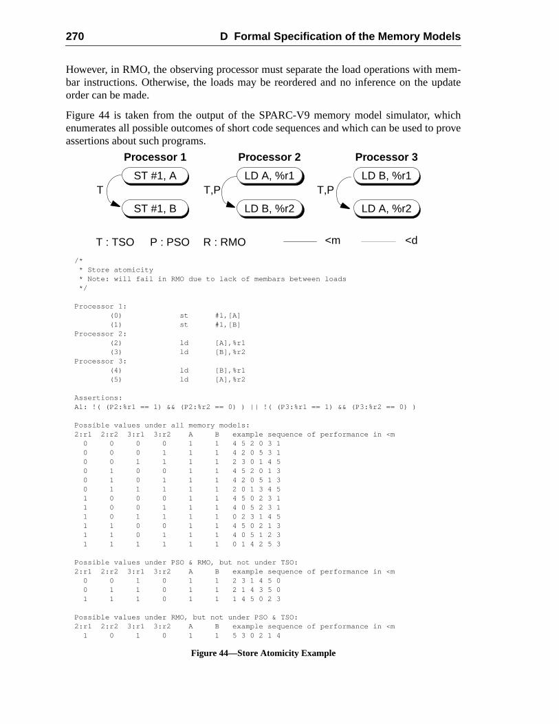
270 D Formal Specification of the Memory Models
mem-pdate
icho prove
However, in RMO, the observing processor must separate the load operations withbar instructions. Otherwise, the loads may be reordered and no inference on the uorder can be made.
Figure 44 is taken from the output of the SPARC-V9 memory model simulator, whenumerates all possible outcomes of short code sequences and which can be used tassertions about such programs.
ST #1, A
ST #1, B
LD A, %r1
LD B, %r2
LD B, %r1
LD A, %r2
T T,P T,P
T : TSO P : PSO R : RMO <d<m
Processor 1 Processor 2 Processor 3
/* * Store atomicity * Note: will fail in RMO due to lack of membars between loads */
Processor 1: (0) st #1,[A] (1) st #1,[B]Processor 2: (2) ld [A],%r1 (3) ld [B],%r2Processor 3: (4) ld [B],%r1 (5) ld [A],%r2
Assertions:A1: !( (P2:%r1 == 1) && (P2:%r2 == 0) ) || !( (P3:%r1 == 1) && (P3:%r2 == 0) )
Possible values under all memory models:2:r1 2:r2 3:r1 3:r2 A B example sequence of performance in <m 0 0 0 0 1 1 4 5 2 0 3 1 0 0 0 1 1 1 4 2 0 5 3 1 0 0 1 1 1 1 2 3 0 1 4 5 0 1 0 0 1 1 4 5 2 0 1 3 0 1 0 1 1 1 4 2 0 5 1 3 0 1 1 1 1 1 2 0 1 3 4 5 1 0 0 0 1 1 4 5 0 2 3 1 1 0 0 1 1 1 4 0 5 2 3 1 1 0 1 1 1 1 0 2 3 1 4 5 1 1 0 0 1 1 4 5 0 2 1 3 1 1 0 1 1 1 4 0 5 1 2 3 1 1 1 1 1 1 0 1 4 2 5 3
Possible values under PSO & RMO, but not under TSO:2:r1 2:r2 3:r1 3:r2 A B example sequence of performance in <m 0 0 1 0 1 1 2 3 1 4 5 0 0 1 1 0 1 1 2 1 4 3 5 0 1 1 1 0 1 1 1 4 5 0 2 3
Possible values under RMO, but not under PSO & TSO:2:r1 2:r2 3:r1 3:r2 A B example sequence of performance in <m 1 0 1 0 1 1 5 3 0 2 1 4
Figure 44—Store Atomicity Example
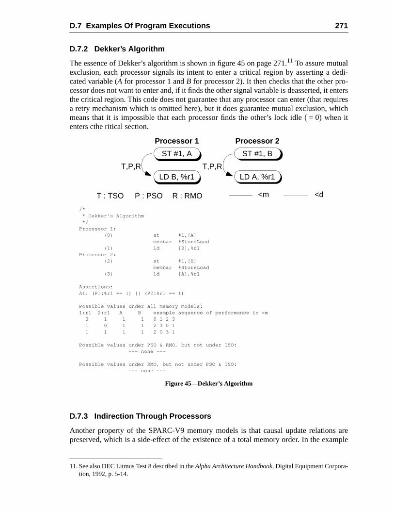
D.7 Examples Of Program Executions 271
dedi-o-entersquireshich
en it
s aremple
D.7.2 Dekker’s Algorithm
The essence of Dekker’s algorithm is shown in figure 45 on page 271.11 To assure mutualexclusion, each processor signals its intent to enter a critical region by asserting acated variable (A for processor 1 andB for processor 2). It then checks that the other prcessor does not want to enter and, if it finds the other signal variable is deasserted, itthe critical region. This code does not guarantee that any processor can enter (that rea retry mechanism which is omitted here), but it does guarantee mutual exclusion, wmeans that it is impossible that each processor finds the other’s lock idle ( = 0) whenters cthe ritical section.
D.7.3 Indirection Through Processors
Another property of the SPARC-V9 memory models is that causal update relationpreserved, which is a side-effect of the existence of a total memory order. In the exa
11. See also DEC Litmus Test 8 described in theAlpha Architecture Handbook, Digital Equipment Corpora-tion, 1992, p. 5-14.
ST #1, A
LD B, %r1
ST #1, B
LD A, %r1T,P,R T,P,R
Processor 1 Processor 2
/* * Dekker's Algorithm */Processor 1: (0) st #1,[A] membar #StoreLoad (1) ld [B],%r1Processor 2: (2) st #1,[B] membar #StoreLoad (3) ld [A],%r1
Assertions:A1: (P1:%r1 == 1) || (P2:%r1 == 1)
Possible values under all memory models:1:r1 2:r1 A B example sequence of performance in <m 0 1 1 1 0 1 2 3 1 0 1 1 2 3 0 1 1 1 1 1 2 0 3 1
Possible values under PSO & RMO, but not under TSO: --- none ---
Possible values under RMO, but not under PSO & TSO: --- none ---
T : TSO P : PSO R : RMO <d<m
Figure 45—Dekker’s Algorithm
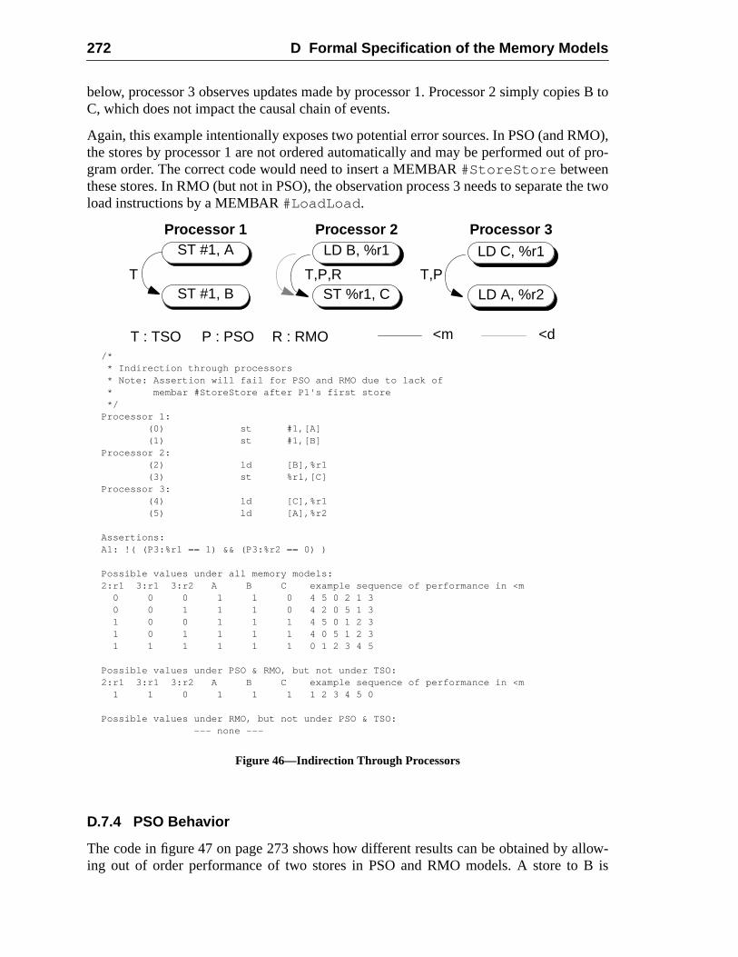
272 D Formal Specification of the Memory Models
ies B to
MO),f pro-
the two
llow-B is
below, processor 3 observes updates made by processor 1. Processor 2 simply copC, which does not impact the causal chain of events.
Again, this example intentionally exposes two potential error sources. In PSO (and Rthe stores by processor 1 are not ordered automatically and may be performed out ogram order. The correct code would need to insert a MEMBAR#StoreStore betweenthese stores. In RMO (but not in PSO), the observation process 3 needs to separateload instructions by a MEMBAR#LoadLoad .
D.7.4 PSO Behavior
The code in figure 47 on page 273 shows how different results can be obtained by aing out of order performance of two stores in PSO and RMO models. A store to
ST #1, A
ST #1, B
LD B, %r1
ST %r1, C
LD C, %r1
LD A, %r2T T,PT,P,R
Processor 1 Processor 2 Processor 3
T : TSO P : PSO R : RMO <d<m/* * Indirection through processors * Note: Assertion will fail for PSO and RMO due to lack of * membar #StoreStore after P1's first store */Processor 1: (0) st #1,[A] (1) st #1,[B]Processor 2: (2) ld [B],%r1 (3) st %r1,[C]Processor 3: (4) ld [C],%r1 (5) ld [A],%r2
Assertions:A1: !( (P3:%r1 == 1) && (P3:%r2 == 0) )
Possible values under all memory models:2:r1 3:r1 3:r2 A B C example sequence of performance in <m 0 0 0 1 1 0 4 5 0 2 1 3 0 0 1 1 1 0 4 2 0 5 1 3 1 0 0 1 1 1 4 5 0 1 2 3 1 0 1 1 1 1 4 0 5 1 2 3 1 1 1 1 1 1 0 1 2 3 4 5
Possible values under PSO & RMO, but not under TSO:2:r1 3:r1 3:r2 A B C example sequence of performance in <m 1 1 0 1 1 1 1 2 3 4 5 0
Possible values under RMO, but not under PSO & TSO: --- none ---
Figure 46—Indirection Through Processors
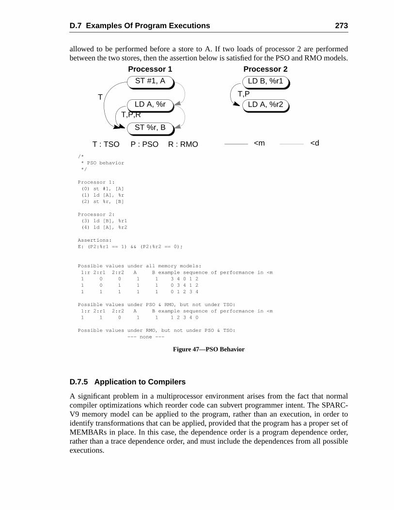
D.7 Examples Of Program Executions 273
medodels.
rmalRC-er toset oforder,ossible
allowed to be performed before a store to A. If two loads of processor 2 are perforbetween the two stores, then the assertion below is satisfied for the PSO and RMO m
D.7.5 Application to Compilers
A significant problem in a multiprocessor environment arises from the fact that nocompiler optimizations which reorder code can subvert programmer intent. The SPAV9 memory model can be applied to the program, rather than an execution, in ordidentify transformations that can be applied, provided that the program has a properMEMBARs in place. In this case, the dependence order is a program dependencerather than a trace dependence order, and must include the dependences from all pexecutions.
ST #1, A
LD A, %r
LD B, %r1
LD A, %r2T,P
ST %r, B
T
T,P,R
Processor 1 Processor 2
T : TSO P : PSO R : RMO <d<m
/* * PSO behavior */
Processor 1: (0) st #1, [A] (1) ld [A], %r (2) st %r, [B]
Processor 2: (3) ld [B], %r1 (4) ld [A], %r2
Assertions:E: (P2:%r1 == 1) && (P2:%r2 == 0);
Possible values under all memory models: 1:r 2:r1 2:r2 A B example sequence of performance in <m 1 0 0 1 1 3 4 0 1 2 1 0 1 1 1 0 3 4 1 2 1 1 1 1 1 0 1 2 3 4
Possible values under PSO & RMO, but not under TSO: 1:r 2:r1 2:r2 A B example sequence of performance in <m 1 1 0 1 1 1 2 3 4 0
Possible values under RMO, but not under PSO & TSO: --- none ---
Figure 47—PSO Behavior
274 D Formal Specification of the Memory Models
uto-dels.vid
eratey fail.moryd the.
gjoon
D.7.6 Verifying Memory Models
While defining the SPARC-V9 memory models, software tools were developed that amatically analyze and formally verify assembly-code sequences running in the moThe core of this collection of tools is the Murphi finite-state verifier developed by DaDill and his students at Stanford University.
For example, these tools can be used to confirm that synchronization routines opproperly in various memory models and to generate counter example traces when theThe tools work by exhaustively enumerating system states in a version of the memodel, so they can only be applied to fairly small assembly code examples. We fountools to be helpful in understanding the memory models and checking our examples12
Contact SPARC International to obtain the verification tools and a set of examples.
12. For a discussion of an earlier application of similar tools to TSO and PSO, see David Dill, SeunPark, and Andreas G. Nowatzyk, “Formal Specification of Abstract Memory Models” inResearch onIntegrated Systems: Proceedings of the 1993 Symposium, Ed. Gaetano Borriello and Carl Ebeling, MITPress, 1993.
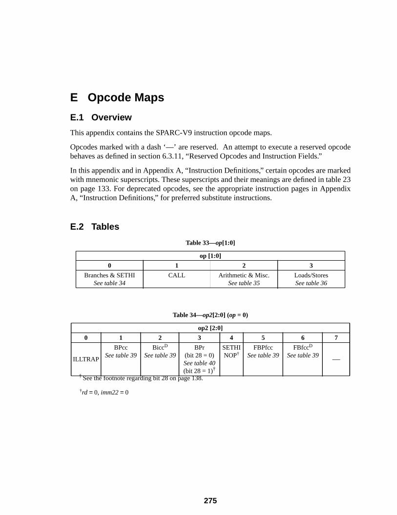
pcode
kedble 23pendix
E Opcode Maps
E.1 Overview
This appendix contains the SPARC-V9 instruction opcode maps.
Opcodes marked with a dash ‘—’ are reserved. An attempt to execute a reserved obehaves as defined in section 6.3.11, “Reserved Opcodes and Instruction Fields.”
In this appendix and in Appendix A, “Instruction Definitions,” certain opcodes are marwith mnemonic superscripts. These superscripts and their meanings are defined in taon page 133. For deprecated opcodes, see the appropriate instruction pages in ApA, “Instruction Definitions,” for preferred substitute instructions.
E.2 Tables
†rd = 0, imm22 = 0
Table 33—op[1:0]
op [1:0]
0 1 2 3
Branches & SETHISee table 34
CALL Arithmetic & Misc.See table 35
Loads/StoresSee table 36
Table 34—op2[2:0] (op= 0)
op2 [2:0]
0 1 2 3 4 5 6 7
ILLTRAP
BPccSee table 39
BiccD
See table 39BPr
(bit 28 = 0)See table 40(bit 28 = 1)†
† See the footnote regarding bit 28 on page 138.
SETHINOP†
FBPfccSee table 39
FBfccD
See table 39 —
275
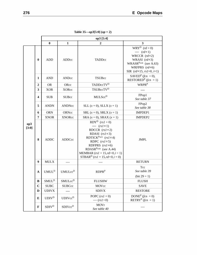
276 E Opcode Maps
Table 35—op3[5:0] (op= 2)
op3 [5:4]
0 1 2 3
op3[3:0]
0 ADD ADDcc TADDcc
WRYD (rd = 0)— (rd= 1)
WRCCR (rd=2)WRASI (rd=3)
WRASRPASR (seeA.63)WRFPRS (rd=6)
SIR (rd=15, rs1=0, i=1)
1 AND ANDcc TSUBccSAVEDP (fcn = 0),
RESTOREDP (fcn = 1)
2 OR ORcc TADDccTVD WRPRP
3 XOR XORcc TSUBccTVD —
4 SUB SUBcc MULSccDFPop1
See table 37
5 ANDN ANDNcc SLL (x = 0), SLLX (x = 1)FPop2
See table 38
6 ORN ORNcc SRL (x = 0), SRLX (x = 1) IMPDEP1
7 XNOR XNORcc SRA (x = 0), SRAX (x = 1) IMPDEP2
8 ADDC ADDCcc
RDYD (rs1= 0)— (rs1= 1)
RDCCR (rs1= 2)RDASI (rs1= 3)
RDTICKPNPT (rs1= 4)RDPC (rs1= 5)
RDFPRS (rs1=6)RDASRPASR (seeA.44)
MEMBAR (rs1= 15,rd=0,i = 1)STBARD (rs1= 15,rd=0,i = 0)
JMPL
9 MULX — — RETURN
A UMULD UMULccD RDPRP
TccSee table 39
(bit 29 = 1)
B SMULD SMULccD FLUSHW FLUSH
C SUBC SUBCcc MOVcc SAVE
D UDIVX — SDIVX RESTORE
E UDIVD UDIVccD POPC (rs1= 0)— (rs1>0)
DONEP (fcn = 0)RETRYP (fcn = 1)
F SDIVD SDIVccD MOVrSee table 40
—
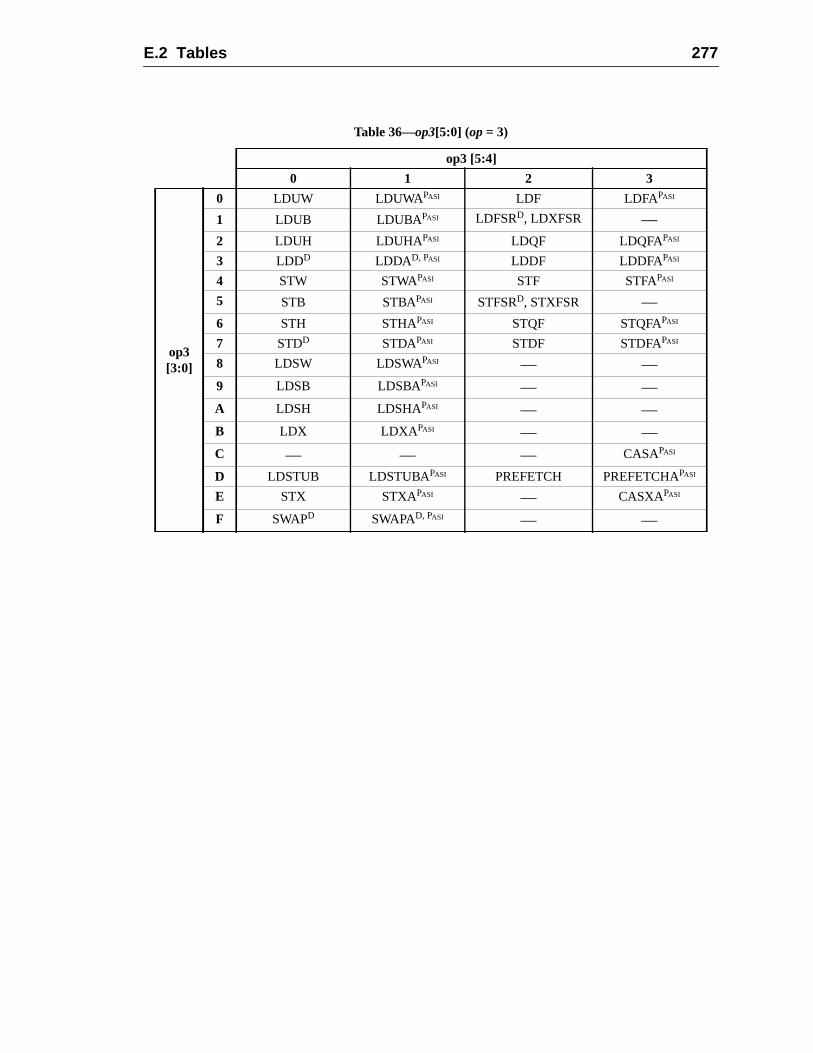
E.2 Tables 277
Table 36—op3[5:0] (op= 3)
op3 [5:4]
0 1 2 3
op3[3:0]
0 LDUW LDUWA PASI LDF LDFAPASI
1 LDUB LDUBA PASI LDFSRD, LDXFSR —2 LDUH LDUHA PASI LDQF LDQFAPASI
3 LDDD LDDAD, PASI LDDF LDDFAPASI
4 STW STWAPASI STF STFAPASI
5 STB STBAPASI STFSRD, STXFSR —6 STH STHAPASI STQF STQFAPASI
7 STDD STDAPASI STDF STDFAPASI
8 LDSW LDSWAPASI — —9 LDSB LDSBAPASI — —A LDSH LDSHAPASI — —B LDX LDXA PASI — —C — — — CASAPASI
D LDSTUB LDSTUBAPASI PREFETCH PREFETCHAPASI
E STX STXAPASI — CASXAPASI
F SWAPD SWAPAD, PASI — —
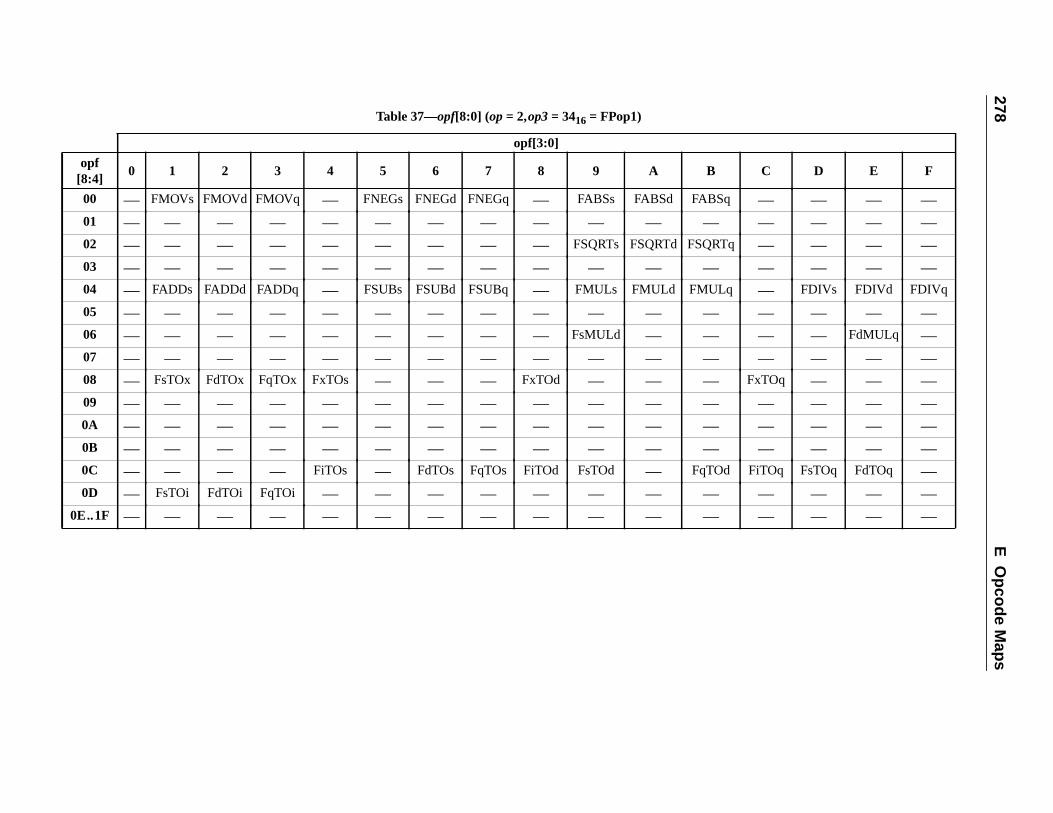
278E
Opcode M
aps
o[8
B C D E F
0 FABSq — — — —0 — — — — —0 FSQRTq — — — —0 — — — — —0 FMULq — FDIVs FDIVd FDIVq
0 — — — — —0 — — — FdMULq —0 — — — — —0 — FxTOq — — —0 — — — — —0 — — — — —0 — — — — —0 FqTOd FiTOq FsTOq FdTOq —0 — — — — —
0E — — — — —
Table 37—opf[8:0] (op= 2,op3= 3416 = FPop1)
opf[3:0]
pf:4]
0 1 2 3 4 5 6 7 8 9 A
0 — FMOVs FMOVd FMOVq — FNEGs FNEGd FNEGq — FABSs FABSd
1 — — — — — — — — — — —2 — — — — — — — — — FSQRTs FSQRTd
3 — — — — — — — — — — —4 — FADDs FADDd FADDq — FSUBs FSUBd FSUBq — FMULs FMULd
5 — — — — — — — — — — —6 — — — — — — — — — FsMULd —7 — — — — — — — — — — —8 — FsTOx FdTOx FqTOx FxTOs — — — FxTOd — —9 — — — — — — — — — — —A — — — — — — — — — — —B — — — — — — — — — — —C — — — — FiTOs — FdTOs FqTOs FiTOd FsTOd —D — FsTOi FdTOi FqTOi — — — — — — —..1F — — — — — — — — — — —
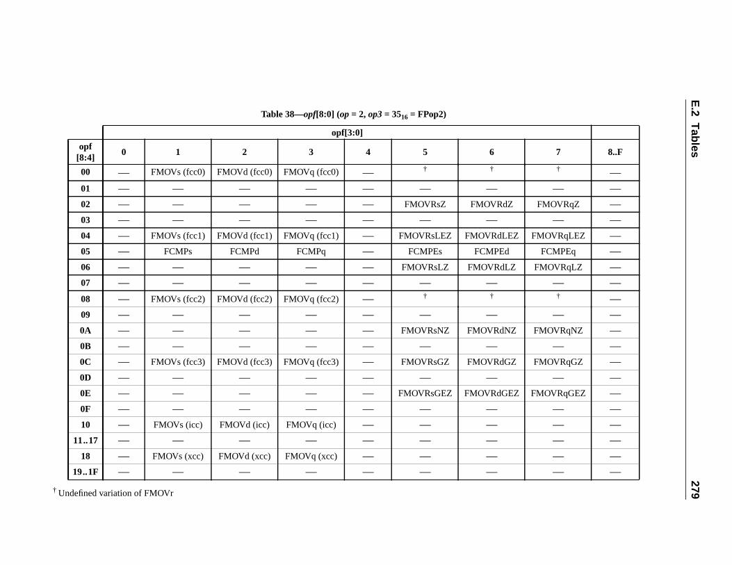
E.2
Tables
279† Undefine
opf[8:4
7 8..F
00 † —01 — —02 Z FMOVRqZ —03 — —04 EZ FMOVRqLEZ —05 d FCMPEq —06 Z FMOVRqLZ —07 — —
08 † —09 — —0A Z FMOVRqNZ —0B — —0C Z FMOVRqGZ —0D — —0E EZ FMOVRqGEZ —0F — —10 — —
11..1 — —18 — —
19..1 — —
d variation of FMOVr
Table 38—opf[8:0] (op= 2, op3= 3516 = FPop2)
opf[3:0]
]0 1 2 3 4 5 6
— FMOVs (fcc0) FMOVd (fcc0) FMOVq (fcc0) — † †
— — — — — — —
— — — — — FMOVRsZ FMOVRd
— — — — — — —
— FMOVs (fcc1) FMOVd (fcc1) FMOVq (fcc1) — FMOVRsLEZ FMOVRdL
— FCMPs FCMPd FCMPq — FCMPEs FCMPE
— — — — — FMOVRsLZ FMOVRdL
— — — — — — —
— FMOVs (fcc2) FMOVd (fcc2) FMOVq (fcc2) — † †
— — — — — — —
— — — — — FMOVRsNZ FMOVRdN
— — — — — — —
— FMOVs (fcc3) FMOVd (fcc3) FMOVq (fcc3) — FMOVRsGZ FMOVRdG
— — — — — — —
— — — — — FMOVRsGEZ FMOVRdG
— — — — — — —
— FMOVs (icc) FMOVd (icc) FMOVq (icc) — — —7 — — — — — — —
— FMOVs (xcc) FMOVd (xcc) FMOVq (xcc) — — —F — — — — — — —
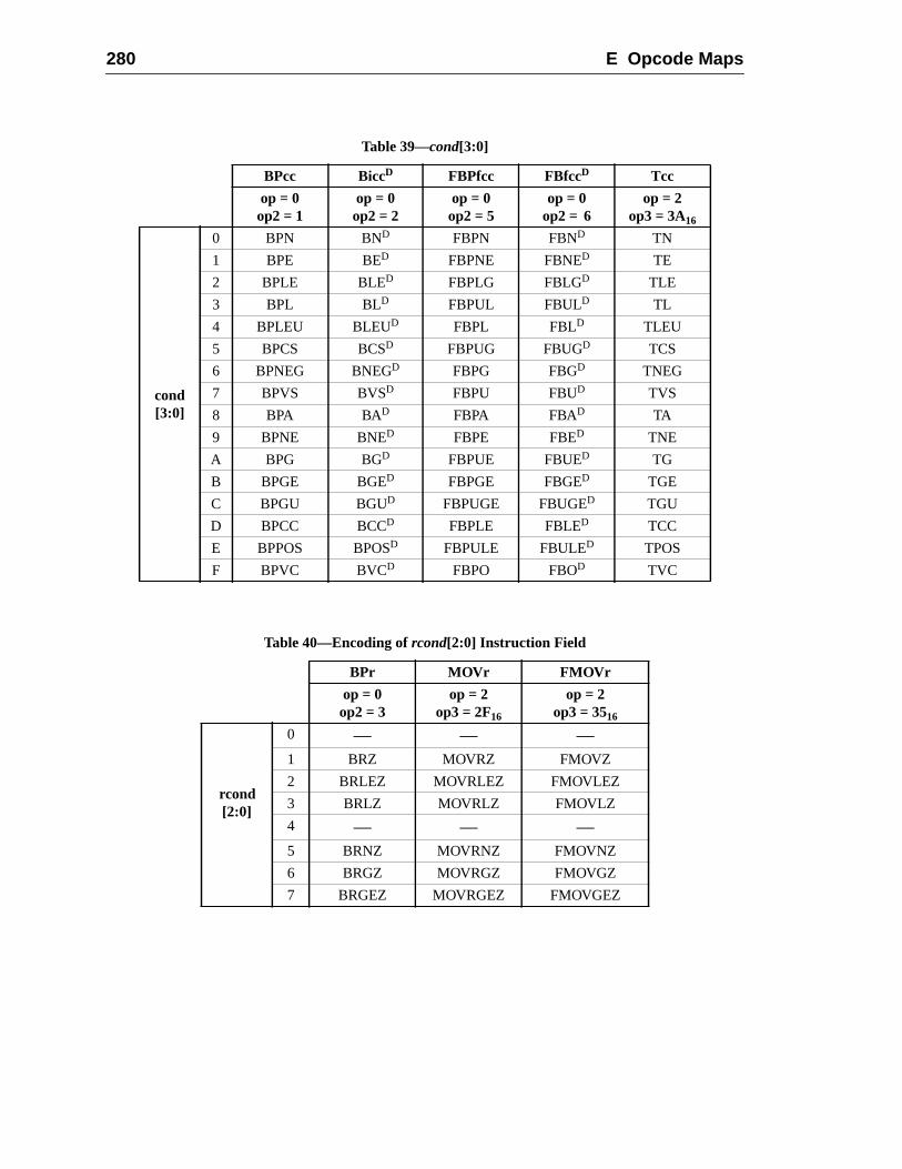
280 E Opcode Maps
Table 39—cond[3:0]
BPcc BiccD FBPfcc FBfccD Tcc
op = 0op2 = 1
op = 0op2 = 2
op = 0op2 = 5
op = 0op2 = 6
op = 2op3 = 3A16
cond[3:0]
0 BPN BND FBPN FBND TN
1 BPE BED FBPNE FBNED TE
2 BPLE BLED FBPLG FBLGD TLE
3 BPL BLD FBPUL FBULD TL
4 BPLEU BLEUD FBPL FBLD TLEU
5 BPCS BCSD FBPUG FBUGD TCS
6 BPNEG BNEGD FBPG FBGD TNEG
7 BPVS BVSD FBPU FBUD TVS
8 BPA BAD FBPA FBAD TA
9 BPNE BNED FBPE FBED TNE
A BPG BGD FBPUE FBUED TG
B BPGE BGED FBPGE FBGED TGE
C BPGU BGUD FBPUGE FBUGED TGU
D BPCC BCCD FBPLE FBLED TCC
E BPPOS BPOSD FBPULE FBULED TPOS
F BPVC BVCD FBPO FBOD TVC
Table 40—Encoding ofrcond[2:0] Instruction Field
BPr MOVr FMOVr
op = 0op2 = 3
op = 2op3 = 2F16
op = 2op3 = 3516
rcond[2:0]
0 — — —1 BRZ MOVRZ FMOVZ
2 BRLEZ MOVRLEZ FMOVLEZ
3 BRLZ MOVRLZ FMOVLZ
4 — — —5 BRNZ MOVRNZ FMOVNZ
6 BRGZ MOVRGZ FMOVGZ
7 BRGEZ MOVRGEZ FMOVGEZ

E.2 Tables 281
Table 41—cc/opf_cc Fields (MOVcc and FMOVcc)
opf_cc Conditioncode selectedcc2 cc1 cc0
0 0 0 fcc0
0 0 1 fcc1
0 1 0 fcc2
0 1 1 fcc3
1 0 0 icc
1 0 1 —1 1 0 xcc
1 1 1 —
Table 42—cc Fields (FBPfcc, FCMP and FCMPE)
cc1 cc0Condition
code selected
0 0 fcc0
0 1 fcc1
1 0 fcc2
1 1 fcc3
Table 43—cc Fields (BPcc and Tcc)
cc1 cc0Condition
code selected
0 0 icc
0 1 —1 0 xcc
1 1 —

282 E Opcode Maps
tisfy.unit. It
ressns.
ysical
e sizeiffer-ationrefer-
es.
ay be
F SPARC-V9 MMU Requirements
F.1 Introduction
This appendix describes the boundary conditions that all SPARC-V9 MMUs must saThe appendix does not define the architecture of any specific memory managementis possible to build a SPARC-V9-compliant system without an MMU.
F.1.1 Definitions
address space:A range of locations accessible with a 64-bit virtual address. Different addspaces may use the same virtual address to refer to different physical locatio
aliases:Two virtual addresses are aliases of each other if they refer to the same phaddress.
context:A set of translations used to support a particular address space.
page:The range of virtual addresses translated by a single translation element. Thof a page is the size of the range translated by a single translation element. Dent pages may have different sizes. Associated with a page or with a translelement are attributes (e.g., restricted, permission, etc.) and statistics (e.g.,enced, modified, etc.)
translation element:Used to translate a range of virtual addresses to a range of physical address
F.2 Overview
All SPARC-V9 MMUs must provide the following basic functions:
— Translate 64-bit virtual addresses to physical addresses. This translation mimplemented with one or more page sizes.
This appendix is informative only.
It is not part of the SPARC-V9 specification.
283
284 F SPARC-V9 MMU Requirements
la-
anyting
ute)
era-s for
ressr.”
. See
Air-s rangerma-
e.RC-
— Provide the RED_state operation, as defined in 7.2.1, “RED_state.”
— Provide a method for disabling the MMU. When the MMU is disabled, no transtion occurs: Physical Address<N:0> = Virtual Address<N:0>, whereN is imple-mentation-dependent. Furthermore, the disabled MMU will not performmemory protection (see F.4.2, “Memory Protection”) or prefetch and non-faulload violation (see F.4.3, “Prefetch and Non-Faulting Load Violation”) checks.
IMPL. DEP. #117: Whether PREFETCH and non-faulting load always succeed when theMMU is disabled is implementation-dependent.
— Provide page-level protections. Conventional protections (Read, Write, Execfor both privileged and nonprivileged accesses may be provided.
— Provide page-level enabling and disabling of prefetch and non-faulting load option. The MMU, however, need not provide separate protection mechanismprefetch and non-faulting load.
— Support multiple address spaces (ASIs). The MMU must support the addspaces as defined in F.3.1, “Information the MMU Expects from the Processo
— Provide page-level statistics such as referenced and modified.
The above requirements apply only to those systems that include SPARC-V9 MMUsF.8, “SPARC-V9 Systems without an MMU.”
F.3 The Processor-MMU Interface
A SPARC-V9 MMU must support at least two types of addresses:
(1) Virtual Addresses, which map all system-wide, program-visible memory.SPARC-V9 MMU may choose not to support translation for the entire 64-bit vtual address space, as long as addresses outside the supported virtual addresare treated either as No_translation or Translation_not_valid (see F.3.3, “Infotion the MMU Sends to the Processor”).
(2) Physical Addresses, which map real physical memory and I/O device spacThere is no minimum requirement for how many physical address bits a SPAV9 MMU must support.
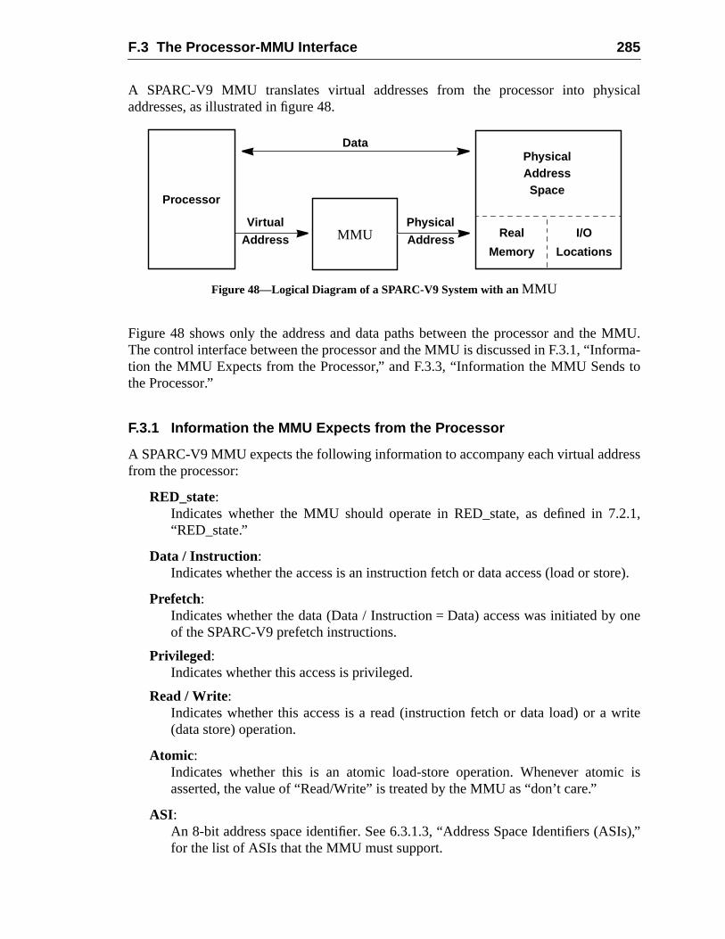
F.3 The Processor-MMU Interface 285
ical
MMU.rma-
s to
ess
.2.1,
tore).
one
write
ic is
Is),”
A SPARC-V9 MMU translates virtual addresses from the processor into physaddresses, as illustrated in figure 48.
Figure 48—Logical Diagram of a SPARC-V9 System with anMMU
Figure 48 shows only the address and data paths between the processor and theThe control interface between the processor and the MMU is discussed in F.3.1, “Infotion the MMU Expects from the Processor,” and F.3.3, “Information the MMU Sendthe Processor.”
F.3.1 Information the MMU Expects from the Processor
A SPARC-V9 MMU expects the following information to accompany each virtual addrfrom the processor:
RED_state:Indicates whether the MMU should operate in RED_state, as defined in 7“RED_state.”
Data / Instruction:Indicates whether the access is an instruction fetch or data access (load or s
Prefetch:Indicates whether the data (Data / Instruction = Data) access was initiated byof the SPARC-V9 prefetch instructions.
Privileged:Indicates whether this access is privileged.
Read / Write:Indicates whether this access is a read (instruction fetch or data load) or a(data store) operation.
Atomic:Indicates whether this is an atomic load-store operation. Whenever atomasserted, the value of “Read/Write” is treated by the MMU as “don’t care.”
ASI:An 8-bit address space identifier. See 6.3.1.3, “Address Space Identifiers (ASfor the list of ASIs that the MMU must support.
I/O
Locations
Processor
Physical
MMU
Address
VirtualAddress
PhysicalAddress
Data
Space
Real
Memory
286 F SPARC-V9 MMU Requirements
alsog uponsed to
ects
n aatomictomicimum,r-i-
indi-.3.1,
with
om-cts”ear on
any
pro-
s fornly
alidvide
F.3.2 Attributes the MMU Associates with Each Mapping
In addition to translating virtual addresses to physical addresses, a SPARC-V9 MMUstores associated attributes, either with each mapping or with each page, dependinthe implementation. Some of these attributes may be associated implicitly, as oppoexplicitly, with the mapping. This information includes
Restricted:Only privileged accesses are allowed (see F.3.1, “Information the MMU Expfrom the Processor”); nonprivileged accesses are disallowed.
Read, Write, and Execute Permissions:An MMU may allow zero or more of read, write, and execute permissions, oper-mapping basis. Read permission is necessary for data read accesses andaccesses. Write permission is necessary for data write accesses and aaccesses. Execute permission is necessary for instruction accesses. At a minan MMU must allow for “all permissions,” “no permissions,” and “no write pemission”; optionally, it can provide “execute only” and “write only,” or any combnation of “read/write/execute” permissions.
Prefetchable:The presence of this attribute indicates that accesses made with the prefetchcation from the processor are allowed; otherwise, they are disallowed. See F“Information the MMU Expects from the Processor.”
Non-faultable:The presence of this attribute indicates that accesses madeASI_PRIMARY_NOFAULT{_LITTLE} and ASI_SECONDARY_NOFAULT{_LITTLE} areallowed; otherwise, they are disallowed. An implementation may choose to cbine the prefetchable and non-faultable attributes into a single “No Side Effeattribute; that is, “reads from this address do not cause side effects, such as clread.”
F.3.3 Information the MMU Sends to the Processor
The processor can expect one and only one of the following signals coming fromSPARC-V9 MMU for each translation requested:
Translation_error :The MMU has detected an error (for example, parity error) in the translationcess. Can cause adata_access_error or instruction_access_error exception.
No_translation:The MMU is unable to translate the virtual address, since no translation existit. Some implementations may not provide this information and provide oTranslation_not_valid. Can cause either adata_access_exception or aninstruction_access_exception exception.
Translation_not_valid:The MMU is unable to translate the virtual address, since it cannot find a vtranslation. Some implementations may not provide this information and pro
F.4 Components of the SPARC-V9 MMU Architecture 287
pagen the
rite,per-
g is
for
ress;
ter-
ress
ical
only No_translation. Can cause either adata_access_MMU_miss or aninstruction_access_MMU_miss exception.
Privilege_violation:The MMU has detected a privilege violation, i.e., an access to a restrictedwhen the access does not have the required privilege (see F.3.1, “InformatioMMU Expects from the Processor”). Can cause either adata_access_protection oran instruction_access_protection exception.
Protection_violation:The MMU has detected a protection violation, which is defined to be a read, wor instruction fetch attempt to a page that does not have read, write, or executemission, respectively. Can cause either adata_access_protection or aninstruction_access_protection exception.
Prefetch_violation:The MMU has detected an attempt to prefetch from a page for which prefetchindisabled.
NF-Load_violation:The MMU has detected an attempt to perform a non-faulting load from a pagewhich non-faulting loads are disabled.
Translation_successful:The MMU has successfully translated the virtual address to a physical addnone of the conditions described above has been detected.
F.4 Components of the SPARC-V9 MMU Architecture
A SPARC-V9 MMU should contain the following:
— Logic that implements virtual-to-physical address translation
— Logic that provides memory protection
— Logic that supports prefetching as noted in A.42, “Prefetch Data”
— Logic that supports non-faulting loading, as noted in 8.3, “Addressing and Alnate Address Spaces”
— A method for specifying the primary, secondary and, optionally, nucleus addspaces
— A method for supplying information related to failed translations
— A method for collecting “referenced” and “modified” statistics
F.4.1 Virtual-to-Physical Address Translation
A SPARC-V9 MMU tries to translate every virtual address it receives into a physaddress as long as:
— The MMU is enabled.
288 F SPARC-V9 MMU Requirements
e thehespace.
oven theithernfor-
theU
s a
sesely
ation
n as
.4.2,
ress
(see
ss is(see
— The processor indicates that this is a non-RED_state instruction fetch (seData/Instruction description in F.3.1, “Information the MMU Expects from tProcessor”) or a data access with an ASI that indicates a translatable address
Although the MMU will attempt to translate every virtual address that meets the abtwo conditions, it need not guarantee that it can provide a translation every time. WheMMU encounters a virtual address that it cannot translate, it asserts eTranslation_error, No_translation, or Translation_not_valid, as discussed in F.3.3, “Imation the MMU Sends to the Processor.”
F.4.2 Memory Protection
For each virtual address for which a SPARC-V9 MMU can provide a translation,MMU checks whether memory protection would be violated. More specifically, the MM
— Indicates Privilege_violation (see F.3.3) if the translation information indicaterestricted page but the access was not privileged (see F.3.1)
— Indicates Protection_violation (see F.3.3) if a read, write, or instruction fetch ua translation that does not grant read, write, or execute permission, respectiv
— Indicates Protection_violation (see F.3.3) if an atomic load-store uses a translthat does not grant both read and write permission
F.4.3 Prefetch and Non-Faulting Load Violation
For each virtual address, the MMU checks for prefetch or non-faulting load violatiolong as
— The MMU can provide a translation, and
— The MMU does not detect any memory protection violation, as discussed in F“Memory Protection.”
More specifically, the MMU performs the following before sending the physical addto the rest of the memory system:
— Asserts Prefetch_violation (see F.3.3) if an access with the prefetch indicationF.3.1) uses a translation that lacks the prefetchable attribute (see F.3.2)
— Asserts NF-Load_violation (see F.3.3) if the ASI (see F.3.1) indicates this accea non-faulting load, but the translation it uses lacks the non-faultable attributeF.3.2)
F.4.4 Contexts
The MMU must support two contexts:
(1) Primary Context
(2) Secondary Context
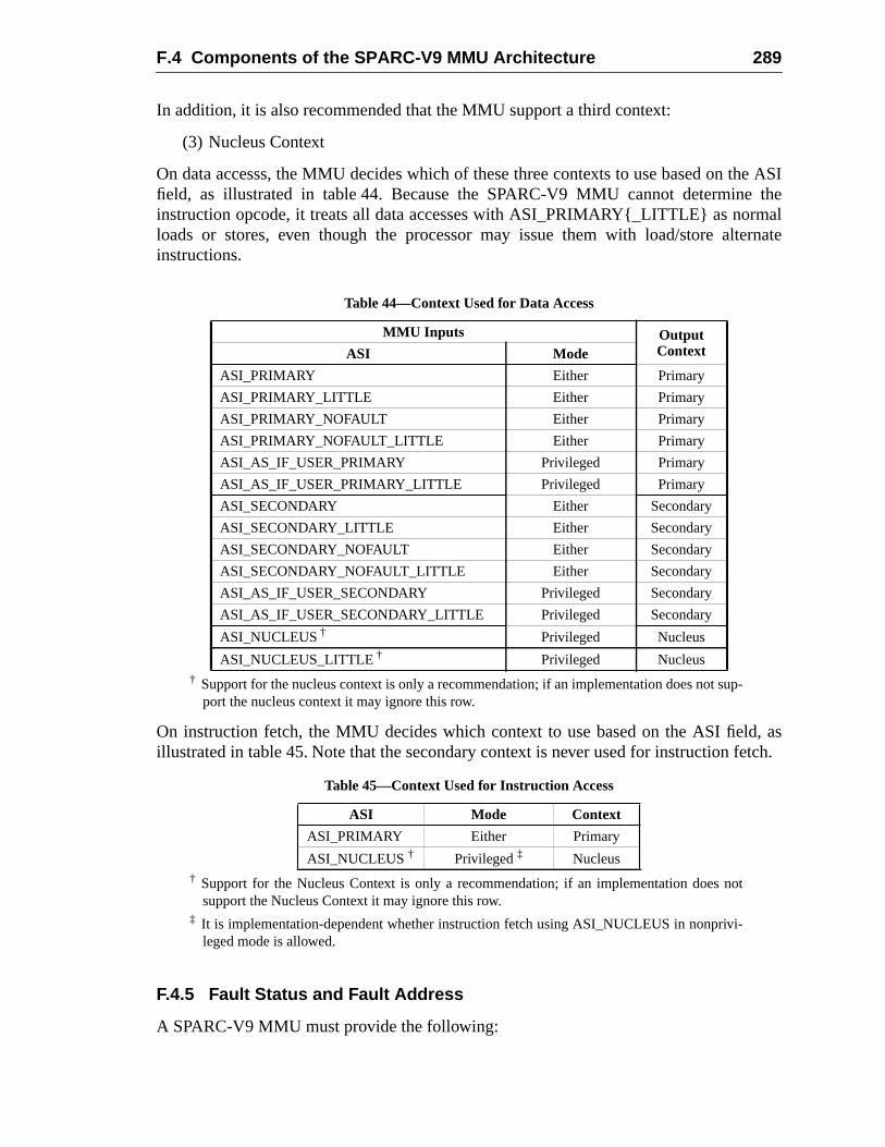
F.4 Components of the SPARC-V9 MMU Architecture 289
he ASItheal
ernate
, asetch.
In addition, it is also recommended that the MMU support a third context:
(3) Nucleus Context
On data accesss, the MMU decides which of these three contexts to use based on tfield, as illustrated in table 44. Because the SPARC-V9 MMU cannot determineinstruction opcode, it treats all data accesses with ASI_PRIMARY{_LITTLE} as normloads or stores, even though the processor may issue them with load/store altinstructions.
† Support for the nucleus context is only a recommendation; if an implementation does not sup-port the nucleus context it may ignore this row.
On instruction fetch, the MMU decides which context to use based on the ASI fieldillustrated in table 45. Note that the secondary context is never used for instruction f
† Support for the Nucleus Context is only a recommendation; if an implementation does notsupport the Nucleus Context it may ignore this row.
‡ It is implementation-dependent whether instruction fetch using ASI_NUCLEUS in nonprivi-leged mode is allowed.
F.4.5 Fault Status and Fault Address
A SPARC-V9 MMU must provide the following:
Table 44—Context Used for Data Access
MMU Inputs OutputContextASI Mode
ASI_PRIMARY Either Primary
ASI_PRIMARY_LITTLE Either Primary
ASI_PRIMARY_NOFAULT Either Primary
ASI_PRIMARY_NOFAULT_LITTLE Either Primary
ASI_AS_IF_USER_PRIMARY Privileged Primary
ASI_AS_IF_USER_PRIMARY_LITTLE Privileged Primary
ASI_SECONDARY Either Secondary
ASI_SECONDARY_LITTLE Either Secondary
ASI_SECONDARY_NOFAULT Either Secondary
ASI_SECONDARY_NOFAULT_LITTLE Either Secondary
ASI_AS_IF_USER_SECONDARY Privileged Secondary
ASI_AS_IF_USER_SECONDARY_LITTLE Privileged Secondary
ASI_NUCLEUS † Privileged Nucleus
ASI_NUCLEUS_LITTLE † Privileged Nucleus
Table 45—Context Used for Instruction Access
ASI Mode Context
ASI_PRIMARY Either Primary
ASI_NUCLEUS† Privileged‡ Nucleus
290 F SPARC-V9 MMU Requirements
ionessor
the
m anMU
tionns-e hasod foratistics
s areformed.
state:
the
t ise alsoe the
ssesemory
tion,ple-t only
ate
— Fault status information that specifies which condition listed in F.3.3, “Informatthe MMU Sends to the Processor,” has resulted in a translation-related proctrap, and any other information necessary for privileged software to determinecause of the trap; for example, ASI, Read/Write, Data/Instruction, etc.
— The Fault address associated with the failed translation. Since the address froinstruction translation failure is available in the processor as the trap PC, the Mis not required to save the address of an instruction translation failure.
F.4.6 Referenced and Modified Statistics
A SPARC-V9 MMU shall allow, either through hardware, software, or some combinathereof, for the collection of “referenced” and “modified” statistics associated with tralations and/or physical pages. That is, there must be a method to determine if a pagbeen referenced, a method to determine if a page has been modified, and a methclearing the indications that a page has been referenced and/or modified. These stmay be kept on either a per-translation basis or a per-physical-page basis.
It is implementation-dependent whether the referenced and/or modified statisticupdated when an access is performed or when the translation for that access is per
F.5 RED_state Processing
It is recommended that the MMU perform as follows when the processor is in RED_
— Instruction address translation is a straight-through physical map; that is,MMU is always suppressed for instruction access in RED_state.
— Data address translation is handled normally; that is, the MMU is used if ienabled. Note that any event which causes the processor to enter RED_statdisables the MMU, however, the handler executing in RED_state may reenablMMU.
F.6 Virtual Address Aliasing
Hardware and privileged software must cooperate so that multiple virtual addrealiased to the same physical address appear to be consistent as defined by the mmodels described in Chapter 8, “Memory Models.” Depending upon the implementathis may require allowing multiple translations to coexist only if they meet some immentation-dependent alignment constraint, or it may require that software ensure thaone translation is in effect at any given time.
F.7 MMU Demap Operation
The SPARC-V9 MMU must provide a mechanism for privileged software to invalidsome or all of the virtual-to-physical address translations.
F.8 SPARC-V9 Systems without an MMU 291
stem
F.8 SPARC-V9 Systems without an MMU
It is possible to build a SPARC-V9 system that does not have an MMU. Such a syshould behave as if contains an MMU that is disabled.

292 F SPARC-V9 MMU Requirements
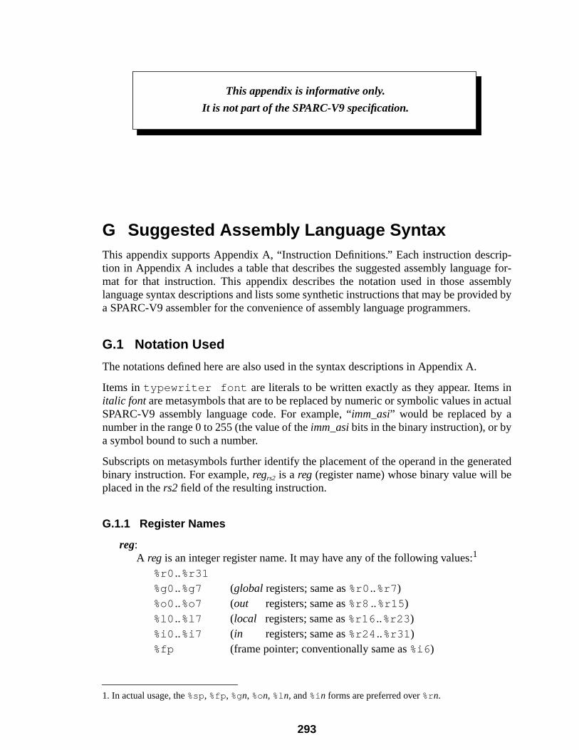
rip-e for-mblyed by
inctual
ratede
G Suggested Assembly Language SyntaxThis appendix supports Appendix A, “Instruction Definitions.” Each instruction desction in Appendix A includes a table that describes the suggested assembly languagmat for that instruction. This appendix describes the notation used in those asselanguage syntax descriptions and lists some synthetic instructions that may be provida SPARC-V9 assembler for the convenience of assembly language programmers.
G.1 Notation Used
The notations defined here are also used in the syntax descriptions in Appendix A.
Items in typewriter font are literals to be written exactly as they appear. Itemsitalic font are metasymbols that are to be replaced by numeric or symbolic values in aSPARC-V9 assembly language code. For example, “imm_asi” would be replaced by anumber in the range 0 to 255 (the value of theimm_asibits in the binary instruction), or bya symbol bound to such a number.
Subscripts on metasymbols further identify the placement of the operand in the genebinary instruction. For example,regrs2 is a reg (register name) whose binary value will bplaced in thers2 field of the resulting instruction.
G.1.1 Register Names
reg:A reg is an integer register name. It may have any of the following values:1
%r0 ..%r31
%g0..%g7 (global registers; same as%r0 ..%r7)%o0..%o7 (out registers; same as%r8 ..%r15)%l0 ..%l7 (local registers; same as%r16 ..%r23)%i0 ..%i7 (in registers; same as%r24 ..%r31)%fp (frame pointer; conventionally same as%i6 )
1. In actual usage, the%sp, %fp, %gn, %on, %ln, and%in forms are preferred over%rn.
This appendix is informative only.
It is not part of the SPARC-V9 specification.
293
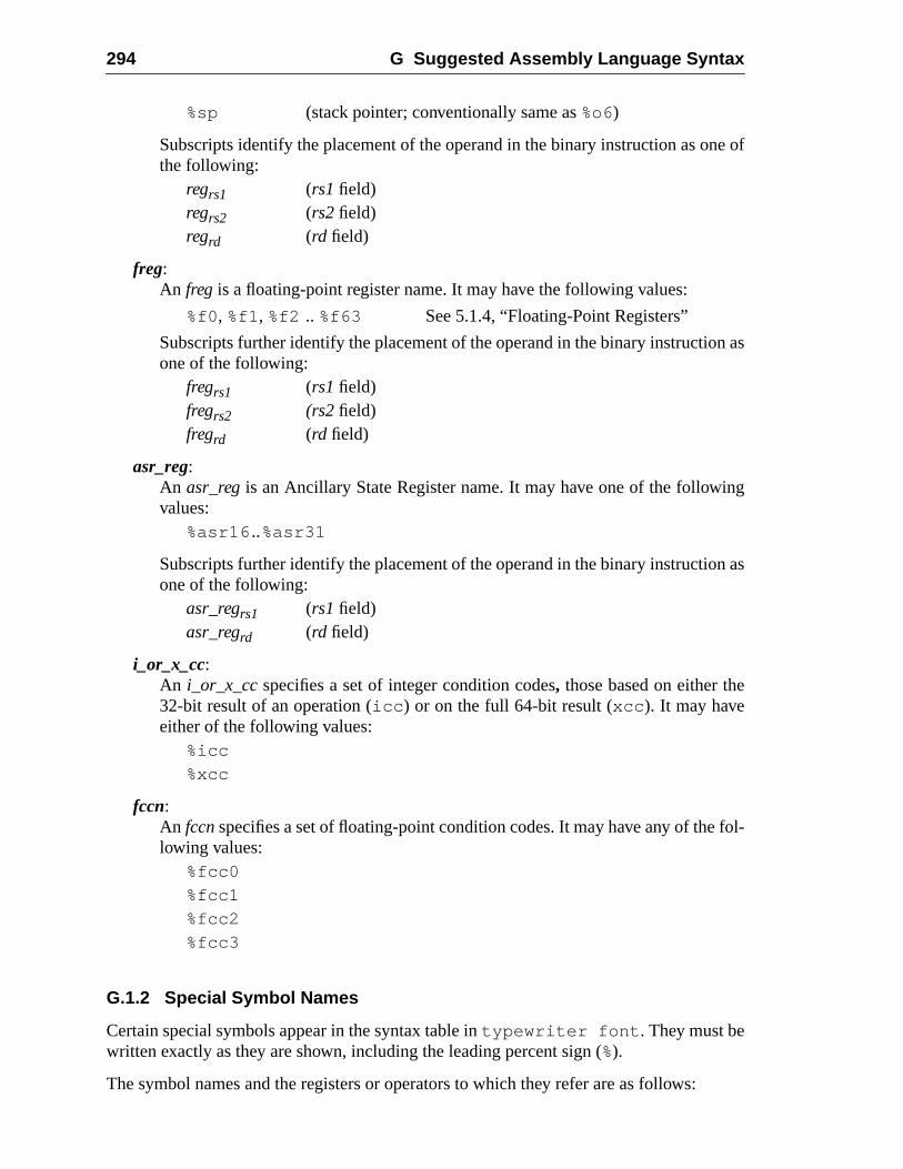
294 G Suggested Assembly Language Syntax
e of
n as
ing
n as
fol-
%sp (stack pointer; conventionally same as%o6)
Subscripts identify the placement of the operand in the binary instruction as onthe following:
regrs1 (rs1 field)regrs2 (rs2 field)regrd (rd field)
freg:An freg is a floating-point register name. It may have the following values:
%f0, %f1, %f2 .. %f63 See 5.1.4, “Floating-Point Registers”
Subscripts further identify the placement of the operand in the binary instructioone of the following:
fregrs1 (rs1 field)fregrs2 (rs2 field)fregrd (rd field)
asr_reg:An asr_regis an Ancillary State Register name. It may have one of the followvalues:
%asr16 ..%asr31
Subscripts further identify the placement of the operand in the binary instructioone of the following:
asr_regrs1 (rs1 field)asr_regrd (rd field)
i_or_x_cc:An i_or_x_ccspecifies a set of integer condition codes, those based on either the32-bit result of an operation (icc ) or on the full 64-bit result (xcc ). It may haveeither of the following values:
%icc
%xcc
fccn:An fccnspecifies a set of floating-point condition codes. It may have any of thelowing values:
%fcc0
%fcc1
%fcc2
%fcc3
G.1.2 Special Symbol Names
Certain special symbols appear in the syntax table intypewriter font . They must bewritten exactly as they are shown, including the leading percent sign (%).
The symbol names and the registers or operators to which they refer are as follows:
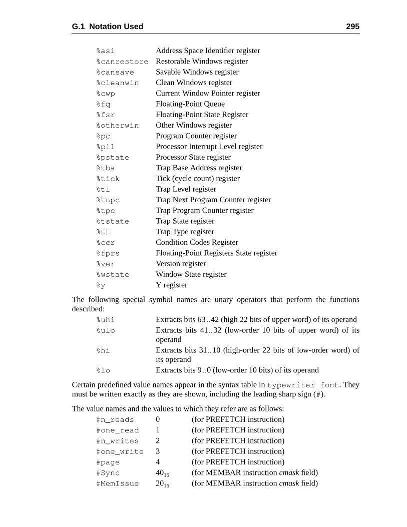
G.1 Notation Used 295
tions
ndts
of
%asi Address Space Identifier register%canrestore Restorable Windows register%cansave Savable Windows register%cleanwin Clean Windows register%cwp Current Window Pointer register%fq Floating-Point Queue%fsr Floating-Point State Register%otherwin Other Windows register%pc Program Counter register%pil Processor Interrupt Level register%pstate Processor State register%tba Trap Base Address register%tick Tick (cycle count) register%tl Trap Level register%tnpc Trap Next Program Counter register%tpc Trap Program Counter register%tstate Trap State register%tt Trap Type register%ccr Condition Codes Register%fprs Floating-Point Registers State register%ver Version register%wstate Window State register%y Y register
The following special symbol names are unary operators that perform the funcdescribed:
%uhi Extracts bits 63..42 (high 22 bits of upper word) of its opera%ulo Extracts bits 41..32 (low-order 10 bits of upper word) of i
operand%hi Extracts bits 31..10 (high-order 22 bits of low-order word)
its operand%lo Extracts bits 9..0 (low-order 10 bits) of its operand
Certain predefined value names appear in the syntax table intypewriter font . Theymust be written exactly as they are shown, including the leading sharp sign (#).
The value names and the values to which they refer are as follows:#n_reads 0 (for PREFETCH instruction)#one_read 1 (for PREFETCH instruction)#n_writes 2 (for PREFETCH instruction)#one_write 3 (for PREFETCH instruction)#page 4 (for PREFETCH instruction)#Sync 4016 (for MEMBAR instructioncmask field)#MemIssue 2016 (for MEMBAR instructioncmask field)
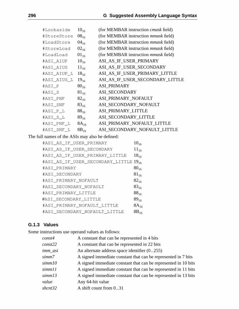
296 G Suggested Assembly Language Syntax
itsbitsbitsbits
#Lookaside 1016 (for MEMBAR instructioncmask field)#StoreStore 0816 (for MEMBAR instructionmmask field)#LoadStore 0416 (for MEMBAR instructionmmask field)#StoreLoad 0216 (for MEMBAR instructionmmask field)#LoadLoad 0116 (for MEMBAR instructionmmask field)#ASI_AIUP 1016 ASI_AS_IF_USER_PRIMARY#ASI_AIUS 1116 ASI_AS_IF_USER_SECONDARY#ASI_AIUP_L 1816 ASI_AS_IF_USER_PRIMARY_LITTLE#ASI_AIUS_L 1916 ASI_AS_IF_USER_SECONDARY_LITTLE#ASI_P 8016 ASI_PRIMARY#ASI_S 8116 ASI_SECONDARY#ASI_PNF 8216 ASI_PRIMARY_NOFAULT#ASI_SNF 8316 ASI_SECONDARY_NOFAULT#ASI_P_L 8816 ASI_PRIMARY_LITTLE#ASI_S_L 8916 ASI_SECONDARY_LITTLE#ASI_PNF_L 8A16 ASI_PRIMARY_NOFAULT_LITTLE#ASI_SNF_L 8B16 ASI_SECONDARY_NOFAULT_LITTLE
The full names of the ASIs may also be defined:#ASI_AS_IF_USER_PRIMARY 1016
#ASI_AS_IF_USER_SECONDARY 1116
#ASI_AS_IF_USER_PRIMARY_LITTLE 1816
#ASI_AS_IF_USER_SECONDARY_LITTLE1916
#ASI_PRIMARY 8016
#ASI_SECONDARY 8116
#ASI_PRIMARY_NOFAULT 8216
#ASI_SECONDARY_NOFAULT 8316
#ASI_PRIMARY_LITTLE 8816
#ASI_SECONDARY_LITTLE 8916
#ASI_PRIMARY_NOFAULT_LITTLE 8A16
#ASI_SECONDARY_NOFAULT_LITTLE 8B16
G.1.3 Values
Some instructions use operand values as follows:const4 A constant that can be represented in 4 bitsconst22 A constant that can be represented in 22 bitsimm_asi An alternate address space identifier (0..255)simm7 A signed immediate constant that can be represented in 7 bsimm10 A signed immediate constant that can be represented in 10 simm11 A signed immediate constant that can be represented in 11 simm13 A signed immediate constant that can be represented in 13 value Any 64-bit valueshcnt32 A shift count from 0..31
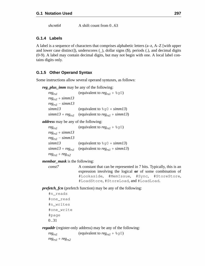
G.1 Notation Used 297
upperdigitson-
an
shcnt64 A shift count from 0..63
G.1.4 Labels
A label is a sequence of characters that comprises alphabetic letters (a–z, A–Z [withand lower case distinct]), underscores (_), dollar signs ($), periods (.), and decimal(0-9). A label may contain decimal digits, but may not begin with one. A local label ctains digits only.
G.1.5 Other Operand Syntax
Some instructions allow several operand syntaxes, as follows:
reg_plus_imm may be any of the following:regrs1 (equivalent toregrs1 + %g0)regrs1+ simm13regrs1 – simm13simm13 (equivalent to%g0 + simm13)simm13+ regrs1 (equivalent toregrs1 + simm13)
address may be any of the following:regrs1 (equivalent toregrs1 + %g0)regrs1+ simm13regrs1 – simm13simm13 (equivalent to%g0 + simm13)simm13+ regrs1 (equivalent toregrs1 + simm13)regrs1+ regrs2
membar_mask is the following:const7 A constant that can be represented in 7 bits. Typically, this is
expression involving the logicalor of some combination of#Lookaside , #MemIssue , #Sync , #StoreStore ,#LoadStore , #StoreLoad , and#LoadLoad .
prefetch_fcn (prefetch function) may be any of the following:#n_reads
#one_read
#n_writes
#one_write
#page
0..31
regaddr (register-only address) may be any of the following:regrs1 (equivalent toregrs1 + %g0)regrs1+ regrs2
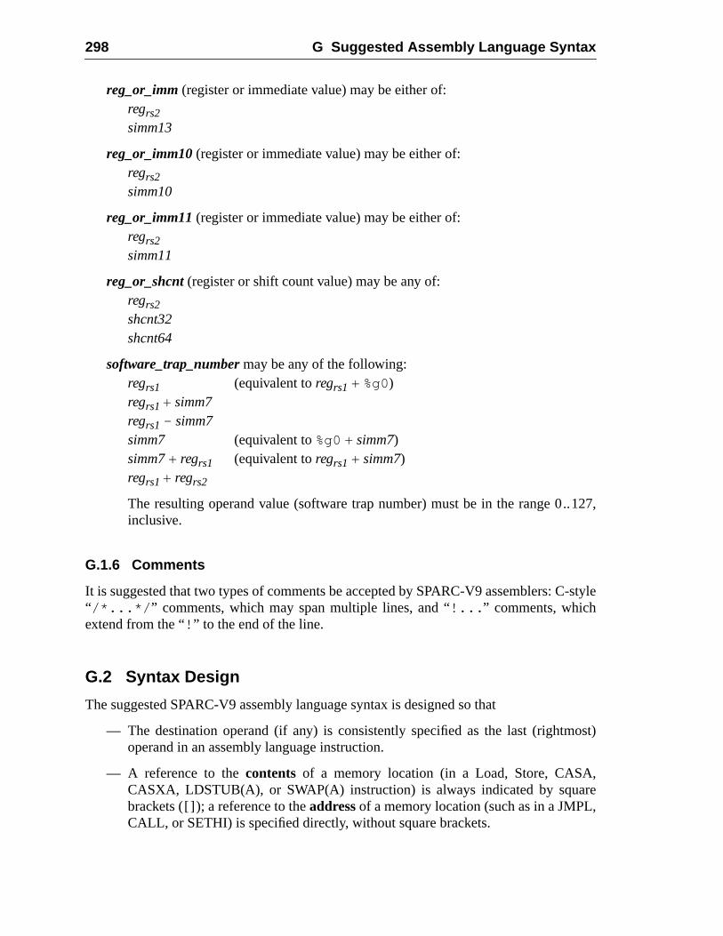
298 G Suggested Assembly Language Syntax
.127,
-style
ost)
,re,
reg_or_imm (register or immediate value) may be either of:regrs2simm13
reg_or_imm10 (register or immediate value) may be either of:regrs2simm10
reg_or_imm11 (register or immediate value) may be either of:regrs2simm11
reg_or_shcnt (register or shift count value) may be any of:regrs2shcnt32shcnt64
software_trap_number may be any of the following:regrs1 (equivalent toregrs1 + %g0)regrs1+ simm7regrs1 – simm7simm7 (equivalent to%g0 + simm7)simm7+ regrs1 (equivalent toregrs1 + simm7)regrs1+ regrs2
The resulting operand value (software trap number) must be in the range 0.inclusive.
G.1.6 Comments
It is suggested that two types of comments be accepted by SPARC-V9 assemblers: C“ /*...*/ ” comments, which may span multiple lines, and “!... ” comments, whichextend from the “! ” to the end of the line.
G.2 Syntax Design
The suggested SPARC-V9 assembly language syntax is designed so that
— The destination operand (if any) is consistently specified as the last (rightmoperand in an assembly language instruction.
— A reference to thecontents of a memory location (in a Load, Store, CASACASXA, LDSTUB(A), or SWAP(A) instruction) is always indicated by squabrackets ([]); a reference to theaddressof a memory location (such as in a JMPLCALL, or SETHI) is specified directly, without square brackets.
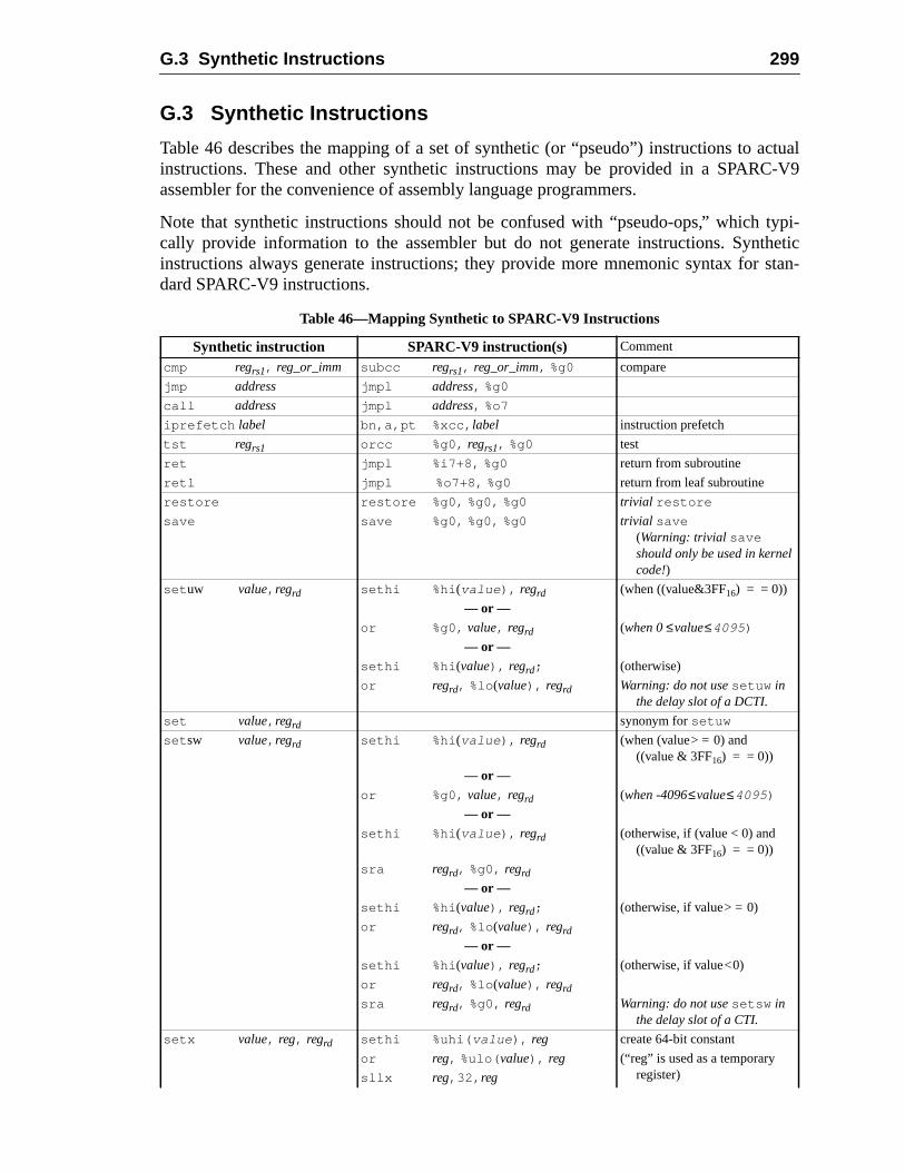
G.3 Synthetic Instructions 299
ctual-V9
typi-heticstan-
G.3 Synthetic Instructions
Table 46 describes the mapping of a set of synthetic (or “pseudo”) instructions to ainstructions. These and other synthetic instructions may be provided in a SPARCassembler for the convenience of assembly language programmers.
Note that synthetic instructions should not be confused with “pseudo-ops,” whichcally provide information to the assembler but do not generate instructions. Syntinstructions always generate instructions; they provide more mnemonic syntax fordard SPARC-V9 instructions.
Table 46—Mapping Synthetic to SPARC-V9 Instructions
Synthetic instruction SPARC-V9 instruction(s) Comment
cmp regrs1, reg_or_imm subcc regrs1, reg_or_imm, %g0 compare
jmp address jmpl address, %g0
call address jmpl address, %o7
iprefetch label bn,a,pt %xcc, label instruction prefetch
tst regrs1 orcc %g0, regrs1, %g0 test
ret jmpl %i7+8, %g0 return from subroutine
retl jmpl %o7+8, %g0 return from leaf subroutine
restore restore %g0, %g0, %g0 trivial restore
save save %g0, %g0, %g0 trivial save(Warning: trivial saveshould only be used in kernelcode!)
set uw value, regrd sethi %hi (value ), regrd (when ((value&3FF16) = = 0))
— or —
or %g0, value, regrd (when 0≤value≤4095 )
— or —
sethi %hi (value), regrd; (otherwise)
or regrd, %lo (value), regrd Warning: do not usesetuw inthe delay slot of a DCTI.
set value, regrd synonym forsetuw
set sw value, regrd sethi %hi (value ), regrd (when (value> = 0) and((value & 3FF16) = = 0))
— or —
or %g0, value, regrd (when -4096≤value≤4095 )
— or —
sethi %hi (value ), regrd (otherwise, if (value < 0) and((value & 3FF16) = = 0))
sra regrd, %g0, regrd
— or —
sethi %hi (value), regrd; (otherwise, if value> = 0)
or regrd, %lo (value), regrd
— or —
sethi %hi (value), regrd; (otherwise, if value<0)
or regrd, %lo (value), regrd
sra regrd, %g0, regrd Warning: do not usesetsw inthe delay slot of a CTI.
setx value, reg, regrd sethi %uhi( value ), reg create 64-bit constant
or reg, %ulo( value), reg (“reg” is used as a temporaryregister)sllx reg,32, reg

300 G Suggested Assembly Language Syntax
sethi %hi( value), regrd Note:set x optimizations arepossible, but not enumer-ated here. The worst-case isshown.Warning: do not useset x in the delay slot of aCTI.
or regrd, reg, regrd
or regrd, %lo( value), regrd
Table 46—Mapping Synthetic to SPARC-V9 Instructions (Continued)
Synthetic instruction SPARC-V9 instruction(s) Comment
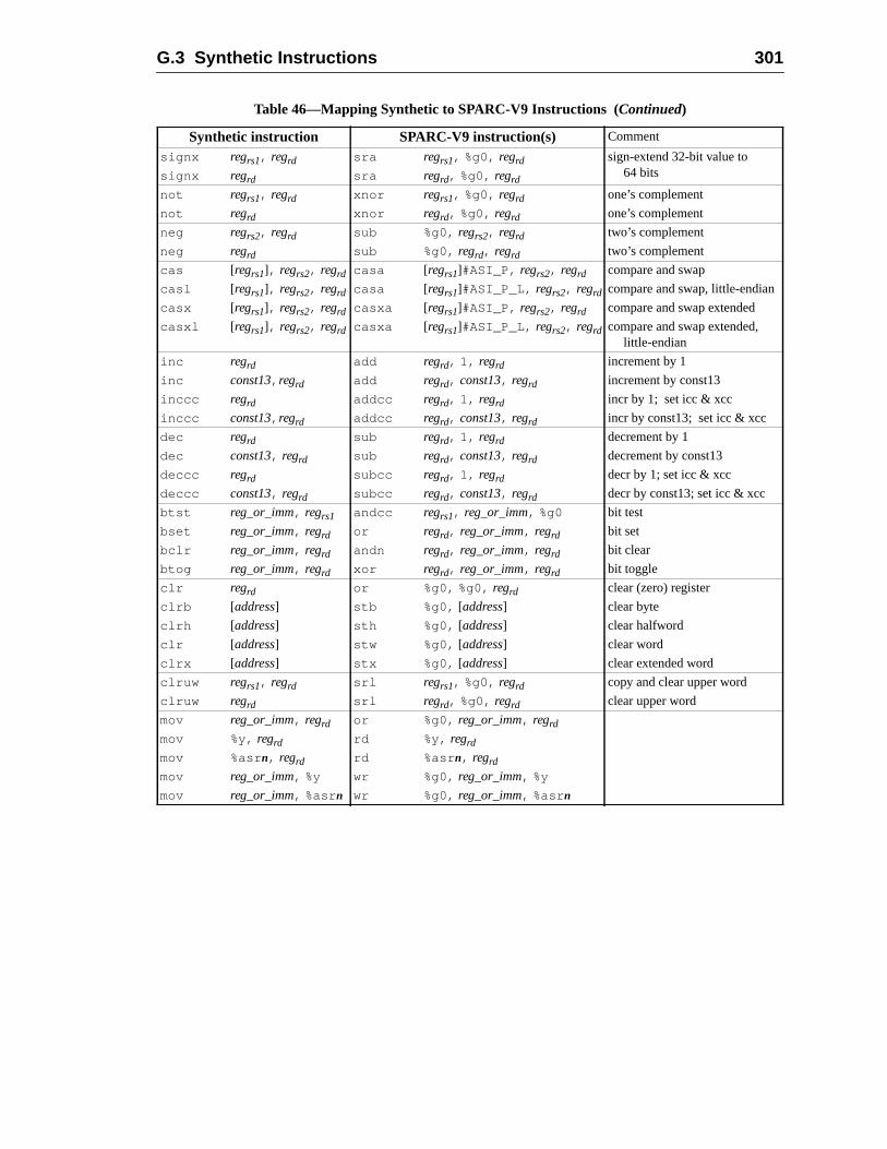
G.3 Synthetic Instructions 301
signx regrs1, regrd sra regrs1, %g0, regrd sign-extend 32-bit value to64 bitssignx regrd sra regrd, %g0, regrd
not regrs1, regrd xnor regrs1, %g0, regrd one’s complement
not regrd xnor regrd, %g0, regrd one’s complement
neg regrs2, regrd sub %g0, regrs2, regrd two’s complement
neg regrd sub %g0, regrd, regrd two’s complement
cas [regrs1], regrs2, regrd casa [regrs1]#ASI_P, regrs2, regrd compare and swap
casl [regrs1], regrs2, regrd casa [regrs1]#ASI_P_L, regrs2, regrd compare and swap, little-endian
casx [regrs1], regrs2, regrd casxa [regrs1]#ASI_P, regrs2, regrd compare and swap extended
casxl [regrs1], regrs2, regrd casxa [regrs1]#ASI_P_L, regrs2, regrd compare and swap extended,little-endian
inc regrd add regrd, 1, regrd increment by 1
inc const13, regrd add regrd, const13, regrd increment by const13
inccc regrd addcc regrd, 1, regrd incr by 1; set icc & xcc
inccc const13, regrd addcc regrd, const13, regrd incr by const13; set icc & xcc
dec regrd sub regrd, 1, regrd decrement by 1
dec const13, regrd sub regrd, const13, regrd decrement by const13
deccc regrd subcc regrd, 1, regrd decr by 1; set icc & xcc
deccc const13, regrd subcc regrd, const13, regrd decr by const13; set icc & xcc
btst reg_or_imm, regrs1 andcc regrs1, reg_or_imm, %g0 bit test
bset reg_or_imm, regrd or regrd, reg_or_imm, regrd bit set
bclr reg_or_imm, regrd andn regrd, reg_or_imm, regrd bit clear
btog reg_or_imm, regrd xor regrd, reg_or_imm, regrd bit toggle
clr regrd or %g0, %g0, regrd clear (zero) register
clrb [address] stb %g0, [address] clear byte
clrh [address] sth %g0, [address] clear halfword
clr [address] stw %g0, [address] clear word
clrx [address] stx %g0, [address] clear extended word
clruw regrs1, regrd srl regrs1, %g0, regrd copy and clear upper word
clruw regrd srl regrd, %g0, regrd clear upper word
mov reg_or_imm, regrd or %g0, reg_or_imm, regrd
mov %y, regrd rd %y, regrd
mov %asrn, regrd rd %asr n, regrd
mov reg_or_imm, %y wr %g0, reg_or_imm, %y
mov reg_or_imm, %asr n wr %g0, reg_or_imm, %asr n
Table 46—Mapping Synthetic to SPARC-V9 Instructions (Continued)
Synthetic instruction SPARC-V9 instruction(s) Comment

302 G Suggested Assembly Language Syntax
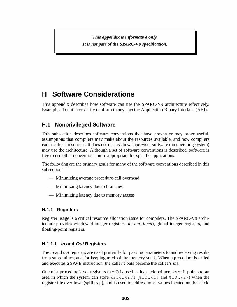
ively.BI).
seful,pilersystem)are is
this
rchi-
sultsalled
stack.
H Software ConsiderationsThis appendix describes how software can use the SPARC-V9 architecture effectExamples do not necessarily conform to any specific Application Binary Interface (A
H.1 Nonprivileged Software
This subsection describes software conventions that have proven or may prove uassumptions that compilers may make about the resources available, and how comcan use those resources. It does not discuss how supervisor software (an operating smay use the architecture. Although a set of software conventions is described, softwfree to use other conventions more appropriate for specific applications.
The following are the primary goals for many of the software conventions described insubsection:
— Minimizing average procedure-call overhead
— Minimizing latency due to branches
— Minimizing latency due to memory access
H.1.1 Registers
Register usage is a critical resource allocation issue for compilers. The SPARC-V9 atecture provides windowed integer registers (in, out, local), global integer registers, andfloating-point registers.
H.1.1.1 In and Out Registers
The in andout registers are used primarily for passing parameters to and receiving refrom subroutines, and for keeping track of the memory stack. When a procedure is cand executes a SAVE instruction, the caller’souts become the callee’sins.
One of a procedure’sout registers (%o6) is used as its stack pointer,%sp. It points to anarea in which the system can store%r16 ..%r31 (%l0 ..%l7 and%i0 ..%i7 ) when theregister file overflows (spill trap), and is used to address most values located on the
This appendix is informative only.
It is not part of the SPARC-V9 specification.
303
304 H Software Considerations
isare
sed in
’s
g-
LL’s
ssthe
or
fewerheticlly)d either
of its
A trap can occur at any time1, which may precipitate a subsequent spill trap. During thspill trap, the contents of the user’s register window at the time of the original trapspilled to the memory to which its%sp points.
A procedure may store temporary values in itsout registers (except%sp) with the under-standing that those values are volatile across procedure calls.%spcannot be used for tem-porary values for the reasons described in H.1.1.3, “Register Windows and %sp.”
Up to six parameters2 may be passed by placing them inout registers%o0..%o5; addi-tional parameters are passed in the memory stack. The stack pointer is implicitly pas%o6, and a CALL instruction places its own address in%o7.3 Floating-point parametersmay also be passed in floating-point registers.
After a callee is entered and its SAVE instruction has been executed, the caller’sout regis-ters are accessible as the callee’sin registers.
The caller’s stack pointer%sp (%o6) automatically becomes the current procedureframe pointer%fp (%i6 ) when the SAVE instruction is executed.
The callee finds its first six integer parameters in%i0 ..%i5 , and the remainder (if any) onthe stack.
A function returns a scalar integer value by writing it into itsins (which are the caller’souts), starting with%i0 . A scalar floating-point value is returned in the floating-point reisters, starting with%f0.
A procedure’s return address, normally the address of the instruction just after the CAdelay-slot instruction, is as%i7+8 .4
H.1.1.2 Local Registers
The locals are used for automatic5 variables and for most temporary values. For acceefficiency, a compiler may also copy parameters (that is, those past the sixth) frommemory stack into thelocals and use them from there.
See H.1.4, “Register Allocation within a Window,” for methods of allocating morefewer than eight registers for local values.
1. For example, due to an error in executing an instruction (for example, amem_address_not_alignedtrap), or due to any type of external interrupt.
2. Six is more than adequate, since the overwhelming majority of procedures in system code takethan six parameters. According to studies cited by Weicker (Weicker, R. P., “Dhrystone: A SyntSystems Programming Benchmark,”CACM 27:10, October 1984), at least 97% (measured staticatake fewer than six parameters. The average number of parameters did not exceed 2.1, measurestatically or dynamically, in any of these studies.
3. If a JMPL instruction is used in place of a CALL, it should place its address in%o7 for consistency.
4. For convenience, SPARC-V9 assemblers may provide a “ret ” (return) synthetic instruction that gener-ates a “jmpl %i7+8 , %g0” hardware instruction. See G.3, “Synthetic Instructions.”
5. In the C language, an automatic variable is a local variable whose lifetime is no longer than thatcontaining procedure.

H.1 Nonprivileged Software 305
o-at
pill/rom
lar,ect-
onerrupt)eenoryalk”
e.
tional
oring
to it
orexe-
l base
era-
ws are
H.1.1.3 Register Windows and %sp
Some caveats about the use of%spand the SAVE and RESTORE instructions are apprpriate. If the operating system and user code use register windows, it is essential th
— %spalwayscontains a correct value, so that when (and if) a register window sfill trap occurs, the register window can be correctly stored to or reloaded fmemory.6
— Nonprivileged code uses SAVE and RESTORE instructions carefully. In particu“walking” the call chain through the register windows using RESTOREs, exping to be able to return to where one started using SAVEs, does not work asmight suppose. Since user code cannot disable traps, a trap (e.g., an intecould write over the contents of a user register window that has “temporarily” bRESTOREd7. The safe method is to flush the register windows to user mem(the stack) by using the FLUSHW instruction. Then, user code can safely “wthe call chain through user memory, instead of through the register windows.
To avoid such problems, consider all data memory at addresses just less than%sp to bevolatile, and the contents of all register windows “below” the current one to be volatil
H.1.1.4 Global Registers
Unlike theins, locals, andouts, theglobals are not part of any register window. Theglo-bals are a set of eight registers with global scope, like the register sets of more tradiprocessor architectures. An ABI may define conventions that theglobals (except%g0)must obey. For example, if the convention assumes thatglobalsare volatile across proce-dure calls, either the caller or the callee must take responsibility for saving and resttheir contents.
Global register%g0has a hardwired value of zero; it always reads as zero, and writeshave no program-visible effect.
Typically, theglobal registers other than%g0are used for temporaries, global variables,global pointers — either user variables, or values maintained as part of the program’scution environment. For example, one could useglobals in the execution environment byestablishing a convention that global scalars are addressed via offsets from a globa
6. Typically, the SAVE instruction is used to generate a new%sp value while shifting to a new registerwindow, all in one atomic operation. When SAVE is used this way, synchronization of the two options should not be a problem.
7. Another reason this might fail is that user code has no way to determine how many register windoimplemented by the hardware.
306 H Software Considerations
ires six
faster
orre-
o beistersrs areoved
,” for
Com-pass
nfor-
rpose
tacks own
ys-t to
es
register. In the most general case, memory accessed at an arbitrary address requinstructions; for example,
sethi %uhi(address), tmpor tmp , %ulo(address), tmpsllx tmp , 32, tmpsethi %hi(address), regor reg , %lo(address), regld [ reg +tmp ], reg
Use of a global base register for frequently accessed global values would provide(single-instruction) access to 213 bytes of those values; for example,
ld [%g n+offset], reg
Additional global registers could be used to provide single-instruction access to cspondingly more global values.
H.1.1.5 Floating-Point Registers
There are sixteen quad-precision floating-point registers. The registers can alsaccessed as thirty-two double-precision registers. In addition, the first eight quad regcan also be accessed as thirty-two single-precision registers. Floating-point registeaccessed with different instructions than the integer registers; their contents can be mamong themselves, and to or from memory. See 5.1.4, “Floating-Point Registersmore information about floating-point register aliasing.
Like the global registers, the floating-point registers must be managed by software.pilers use the floating-point registers for user variables and compiler temporaries,floating-point parameters, and return floating-point results in them.
H.1.1.6 The Memory Stack
A stack is maintained to hold automatic variables, temporary variables, and return imation for each invocation of a procedure. When a procedure is called, astack frame isallocated; it is released when the procedure returns. The use of a stack for this puallows simple and efficient implementation of recursive procedures.
Under certain conditions, optimization can allow a leaf procedure to use its caller’s sframe instead of one of its own. In that case, the procedure allocates no space of itfor a stack frame. See H.1.2, “Leaf-Procedure Optimization,” for more information.
The stack pointer%spmust always maintain the alignment required by the operating stem’s ABI. This is at least doubleword alignment, possibly with a constant offseincrease stack addressability using constant offset addressing.
H.1.2 Leaf-Procedure Optimization
A leaf procedure is one that is a “leaf” in the program’s call graph; that is, one that donot call (e.g., via CALL or JMPL) any other procedures.
H.1 Nonprivileged Software 307
ate aORE
ap-ral
ects of
edure
ger
g its. Thisyall.
wing
caller
n of
egister
com-
Each procedure, including leaf procedures, normally uses a SAVE instruction to allocstack frame and obtain a register window for itself, and a corresponding RESTinstruction to deallocate it. The time costs associated with this are
— Possible generation of register-window spill/fill traps at runtime. This only hpens occasionally,8 but when either a spill or fill trap does occur, it costs sevemachine cycles to process.
— The cycles expended by the SAVE and RESTORE instructions themselves.
There are also space costs associated with this convention, the cumulative cache effwhich may be nonnegligible. The space costs include
— The space occupied on the stack by the procedure’s stack frame
— The two words occupied by the SAVE and RESTORE instructions
Of the above costs, the trap-processing cycles typically are the most significant.
Some leaf procedures can be made to operatewithout their own register window or stackframe, using their caller’s instead. This can be done when the candidate leaf procmeets all of the following conditions:9
— It contains no references to%sp, except in its SAVE instruction.
— It contains no references to%fp.
— It refers to (or can be made to refer to) no more than eight of the thirty-two interegisters, including%o7 (the return address).
If a procedure conforms to the above conditions, it can be made to operate usincaller’s stack frame and registers, an optimization that saves both time and spaceoptimization is calledleaf procedure optimization. The optimized procedure may safeluse only registers that its caller already assumes to be volatile across a procedure c
The optimization can be performed at the assembly language level using the follosteps:
(1) Change all references to registers in the procedure to registers that theassumes volatile across the call.
(a) Leave references to%o7 unchanged.
(b) Leave any references to%g0..%g7 unchanged.
(c) Change%i0 ..%i5 to %o0..%o5, respectively. If anin register is changed to anout register that was already referenced in the original unoptimized versiothe procedure, all original references to thatout register must be changed torefer to an unusedout or global register.
8. The frequency of overflow and underflow traps depends on the application and on the number of rwindows (NWINDOWS) implemented in hardware.
9. Although slightly less restrictive conditions could be used, the optimization would become moreplex to perform and the incremental gain would usually be small.
308 H Software Considerations
ter
P
seorre-andin
ce-
ns ora
o ref-
ross a
ndi-
tack
imple
, and
opti-
SAVEs of
(d) Change references to eachlocal register into references to any unused registhat is assumed to be volatile across a procedure call.
(2) Delete the SAVE instruction. If it was in a delay slot, replace it with a NOinstruction. If its destination register was not%g0or %sp, convert the SAVE intothe corresponding ADD instruction instead of deleting it.
(3) If the RESTORE’s implicit addition operation is used for a productive purpo(such as setting the procedure’s return value), convert the RESTORE to the csponding ADD instruction. Otherwise, the RESTORE is only used for stackregister-window deallocation; replace it with a NOP instruction (it is probablythe delay slot of the RET, and so cannot be deleted).
(4) Change the RET (return) synthetic instruction to RETL (return-from-leaf-produre synthetic instruction).
(5) Perform any optimizations newly made possible, such as combining instructiofilling the delay slot of the RETL (or the delay slot occupied by the SAVE) withproductive instruction.
After the above changes, there should be no SAVE or RESTORE instructions, and nerences toin or local registers in the procedure body. All original references toins are nowto outs. All other register references are to registers that are assumed to be volatile acprocedure call.
Costs of optimizing leaf procedures in this way include
— Additional intelligence in a peephole optimizer to recognize and optimize cadate leaf procedures
— Additional intelligence in debuggers to properly report the call chain and the straceback for optimized leaf procedures10
H.1.3 Example Code for a Procedure Call
This subsection illustrates common parameter-passing conventions and gives a sexample of leaf-procedure optimization.
The code fragment in example 1 shows a simple procedure call with a value returnedthe procedure itself.
Sincesum3 does not call any other procedures (i.e., it is a leaf procedure), it can bemized to become:
sum3:add %o0, %o1, %o0retl ! (must use RETL, not RET,add %o0, %o2, %o0 ! to return from leaf procedure)
10. A debugger can recognize an optimized leaf procedure by scanning it, noting the absence of ainstruction. Compilers often constrain the SAVE, if present, to appear within the first few instructiona procedure; in such a case, only those instruction positions need be examined.
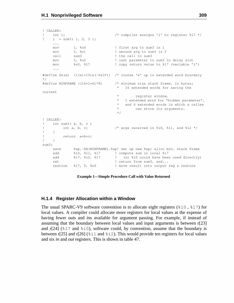
H.1 Nonprivileged Software 309
se ofofr[23]
y iss
H.1.4 Register Allocation within a Window
The usual SPARC-V9 software convention is to allocate eight registers (%l0 ..%l7 ) forlocal values. A compiler could allocate more registers for local values at the expenhaving fewerouts and ins available for argument passing. For example, if insteadassuming that the boundary between local values and input arguments is betweenand r[24] (%l7 and %i0 ), software could, by convention, assume that the boundarbetween r[25] and r[26] (%i1 and%i2 ). This would provide ten registers for local valueand sixin andout registers. This is shown in table 47.
! CALLER:! int i; /* compiler assigns "i" to register %l7 */! i = sum3( 1, 2, 3 );
...mov 1, %o0 ! first arg to sum3 is 1mov 2, %o1 ! second arg to sum3 is 2call sum3 ! the call to sum3mov 3, %o2 ! last parameter to sum3 in delay slotmov %o0, %l7 ! copy return value to %l7 (variable "i")...
#define SA(x) (((x)+15)&(~0x1F)) /* rounds "x" up to extended word boundary*/#define MINFRAME ((16+1+6)*8) /* minimum size stack frame, in bytes;
* 16 extended words for saving thecurrent
* register window, * 1 extended word for “hidden parameter”, * and 6 extended words in which a callee * can store its arguments. */
! CALLEE:! int sum3( a, b, c )! int a, b, c; /* args received in %i0, %i1, and %i2 */! {! return a+b+c;! }sum3:
save %sp,-SA(MINFRAME),%sp! set up new %sp; alloc min. stack frameadd %i0, %i1, %l7 ! compute sum in local %l7add %l7, %i2, %l7 ! (or %i0 could have been used directly)ret ! return from sum3, and...restore %l7, 0, %o0 ! move result into output reg & restore
Example 1—Simple Procedure Call with Value Returned
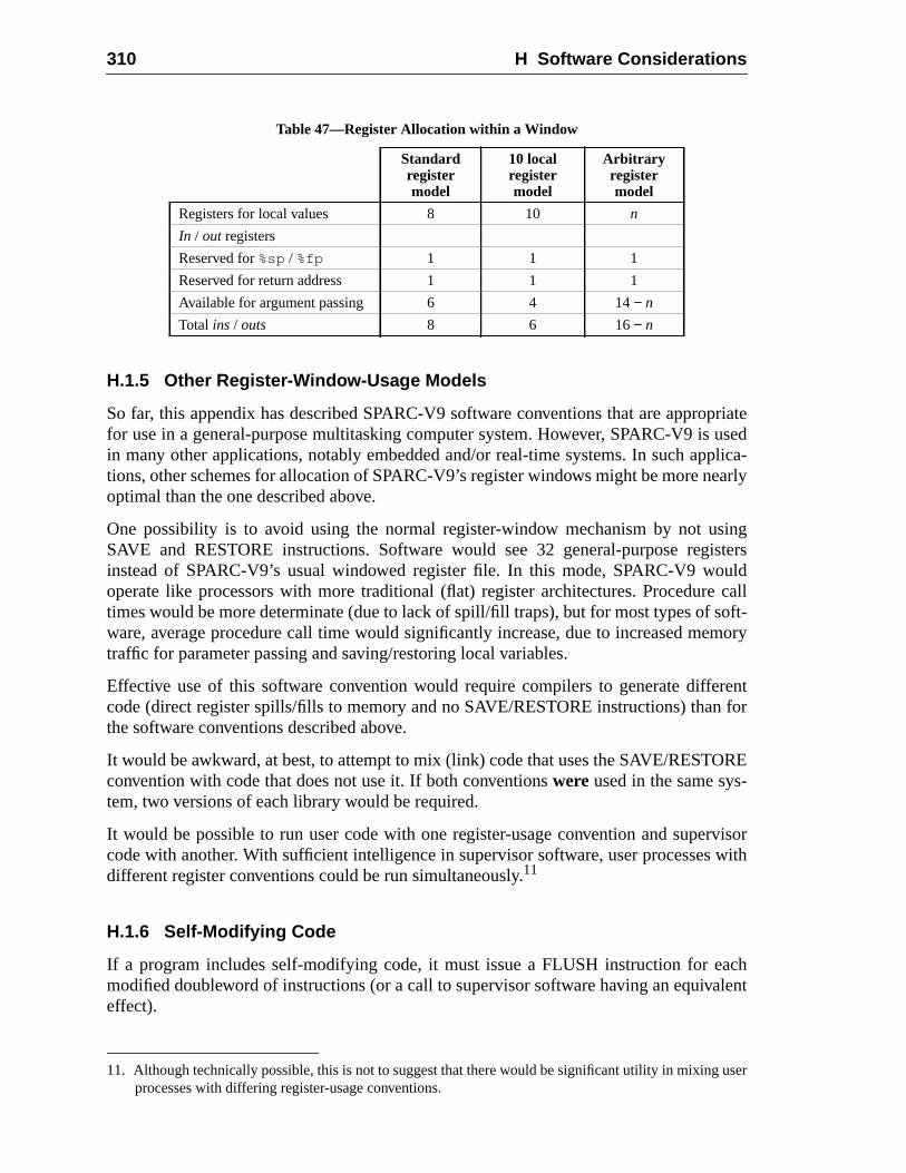
310 H Software Considerations
priateusedplica-arly
singistersulde calloft-mory
rentfor
RE-
rvisorwith
achlent
user
H.1.5 Other Register-Window-Usage Models
So far, this appendix has described SPARC-V9 software conventions that are approfor use in a general-purpose multitasking computer system. However, SPARC-V9 isin many other applications, notably embedded and/or real-time systems. In such aptions, other schemes for allocation of SPARC-V9’s register windows might be more neoptimal than the one described above.
One possibility is to avoid using the normal register-window mechanism by not uSAVE and RESTORE instructions. Software would see 32 general-purpose reginstead of SPARC-V9’s usual windowed register file. In this mode, SPARC-V9 wooperate like processors with more traditional (flat) register architectures. Procedurtimes would be more determinate (due to lack of spill/fill traps), but for most types of sware, average procedure call time would significantly increase, due to increased metraffic for parameter passing and saving/restoring local variables.
Effective use of this software convention would require compilers to generate diffecode (direct register spills/fills to memory and no SAVE/RESTORE instructions) thanthe software conventions described above.
It would be awkward, at best, to attempt to mix (link) code that uses the SAVE/RESTOconvention with code that does not use it. If both conventionswere used in the same system, two versions of each library would be required.
It would be possible to run user code with one register-usage convention and supecode with another. With sufficient intelligence in supervisor software, user processesdifferent register conventions could be run simultaneously.11
H.1.6 Self-Modifying Code
If a program includes self-modifying code, it must issue a FLUSH instruction for emodified doubleword of instructions (or a call to supervisor software having an equivaeffect).
Table 47—Register Allocation within a Window
Standardregistermodel
10 localregistermodel
Arbitraryregistermodel
Registers for local values 8 10 n
In / out registers
Reserved for%sp / %fp 1 1 1
Reserved for return address 1 1 1
Available for argument passing 6 4 14− n
Total ins / outs 8 6 16− n
11. Although technically possible, this is not to suggest that there would be significant utility in mixingprocesses with differing register-usage conventions.
H.1 Nonprivileged Software 311
tion
dian
A,ata
cost
PU.F bitientreg-oft-
.4,
is-e are
imize
cans and/
Note that self-modifying code intended to be portablemust use FLUSH instruction(s) (ora call to supervisor software having equivalent effect) after storing into the instrucstream.
All SPARC-V9 instruction accesses are big-endian. If a program is running in little-enmode and wishes to modify instructions, it must do one of the following:
— Use an explicit big-endian ASI to write the modified instruction to memory, or
— Reverse the byte ordering shown in the instruction formats in Appendix“Instruction Definitions,” before doing a little-endian store, since the stored dwill be reordered before the bytes are written to memory.
H.1.7 Thread Management
SPARC-V9 provides support for the efficient management of user-level threads. Theof thread switching can be reduced by using the following features:
User Management of FPU:The FEF bit in the FPRS register allows nonprivileged code to manage the FThis is in addition to the management done by the supervisor code via the PEin the PSTATE register. A thread-management library can implement efficswitching of the FPU among threads by manipulating the FEF bit in the FPRSister and by providing a user trap handler (with support from the supervisor sware) for thefp_disabled exception. See the description of User Traps in H.2“User Trap Handlers.”
FLUSHW Instruction :The FLUSHW instruction is an efficient way for a thread library to flush the regter windows during a thread switch. The instruction executes as a NOP if therno windows to flush.
H.1.8 Minimizing Branch Latency
The SPARC-V9 architecture contains several instructions that can be used to minbranch latency. These are described below.
Conditional Moves:The conditional move instructions for both integer and floating-point registersbe used to eliminate branches from the code generated for simple expressionor assignments. The following example illustrates this.
The C code segment
double x,y;int i;...i = (x > y) ? 1 : 2;
312 H Software Considerations
llows-
s. Itin-
ticple.
the
the
and)
es ofededthe
rfield,ort
ting
can be compiled to use a conditional move as follows:
fcmp %fcc1, x, y ! x and y are double regsmov 1, i ! i is int; assume x > ymovfle %fcc1, 2, i ! fix i if wrong
Branch or Move Based on Register Contents:The use of register contents as conditions for branch and move instructions aany integer register (other thanr0) to hold a boolean value or the results of a comparison. This allows conditions to be used more efficiently in nested caseallows the generation of a condition to be moved further from its use, thereby mimizing latency. In addition, it can eliminate the need for additional arithmeinstructions to set the condition codes. This is illustrated in the following exam
The test for finding the maximum of an array of integers,
if (A[i] > max)max = A[i];
can be compiled as follows, allowing the condition for the loop to be set beforesequence and checked after it:
ldx [ addr_of_Ai], Aisub Ai, max, tmpmovrgz tmp, Ai, max
H.1.9 Prefetch
The SPARC-V9 architecture includes a prefetch instruction intended to help hidelatency of accessing memory.12
As a general rule, given a loop of the following form (using C for assembly language,assuming a cache line size of 64 bytes and that A and B are arrays of 8-byte values
for (i = 0; i < N; i++) {load A[i]
load B[i]
...
}
which takes C cycles per iteration (assuming all loads hit in cache) and given L cycllatency to memory, prefetch instructions may be inserted for data that will be neceiling(L/C') iterations in the future, where C' is number of cycles per iteration ofmodified loop. Thus, the loop would be transformed into
12. Two papers describing the use of prefetch instructions are Callahan, D., K. Kennedy, A. Porte“Software Prefetching,”Proceedings of the Fourth International Conference on Architectural Suppfor Programming Languages and Operating Systems, April 1991, pp. 40-52, and Mowry, T., M. Lam,and A. Gupta, “Design and Evaluation of a Compiler Algorithm for Prefetching,”Proceedings of theFifth International Conference on Architectural Support for Programming Languages and OperaSystems, October 1992, pp. 62-73.
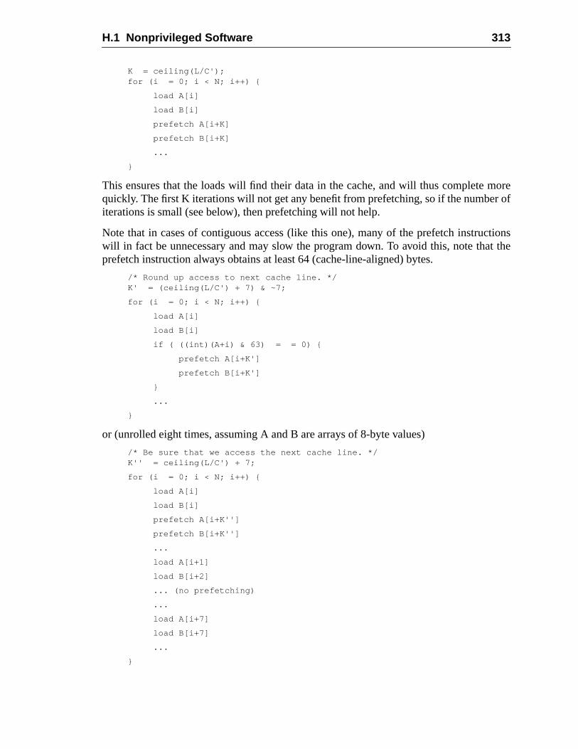
H.1 Nonprivileged Software 313
morer of
tionst the
K = ceiling(L/C');for (i = 0; i < N; i++) {
load A[i]
load B[i]
prefetch A[i+K]
prefetch B[i+K]
...
}
This ensures that the loads will find their data in the cache, and will thus completequickly. The first K iterations will not get any benefit from prefetching, so if the numbeiterations is small (see below), then prefetching will not help.
Note that in cases of contiguous access (like this one), many of the prefetch instrucwill in fact be unnecessary and may slow the program down. To avoid this, note thaprefetch instruction always obtains at least 64 (cache-line-aligned) bytes.
/* Round up access to next cache line. */K' = (ceiling(L/C') + 7) & ~7;
for (i = 0; i < N; i++) {
load A[i]
load B[i]
if ( ((int)(A+i) & 63) = = 0) {
prefetch A[i+K']
prefetch B[i+K']
}
...
}
or (unrolled eight times, assuming A and B are arrays of 8-byte values)
/* Be sure that we access the next cache line. */K'' = ceiling(L/C') + 7;
for (i = 0; i < N; i++) {
load A[i]
load B[i]
prefetch A[i+K'']
prefetch B[i+K'']
...
load A[i+1]
load B[i+2]
... (no prefetching)
...
load A[i+7]
load B[i+7]
...
}
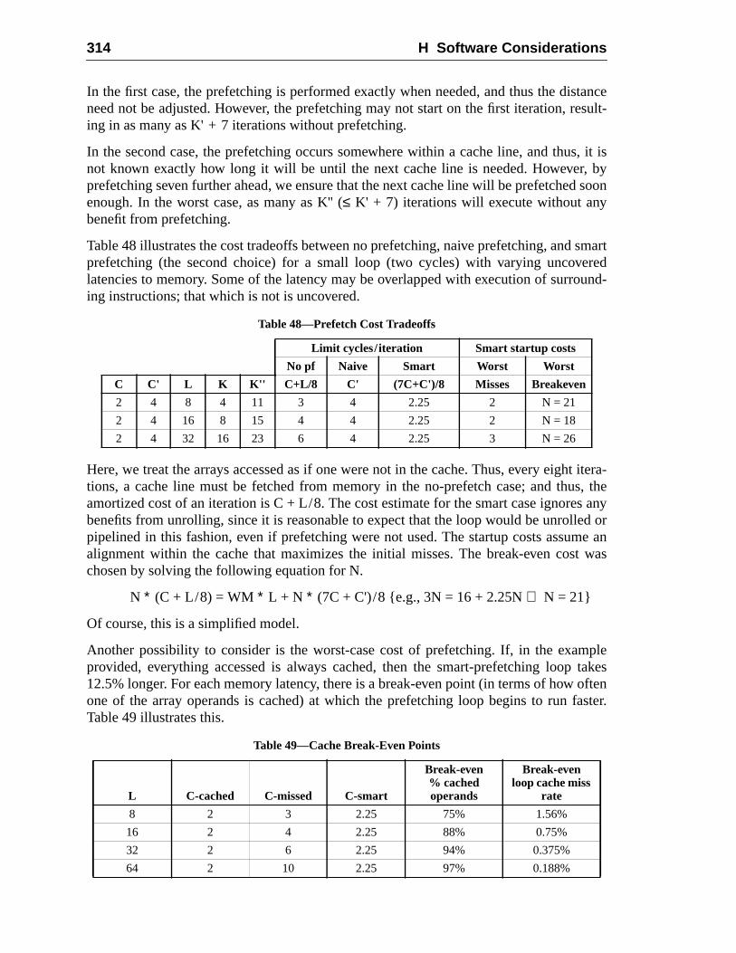
314 H Software Considerations
tanceesult-
s, it isby
d soon
smartredund-
t itera-s, thes anyd ore an
t was
pletakes
oftenaster.
In the first case, the prefetching is performed exactly when needed, and thus the disneed not be adjusted. However, the prefetching may not start on the first iteration, ring in as many as K' + 7 iterations without prefetching.
In the second case, the prefetching occurs somewhere within a cache line, and thunot known exactly how long it will be until the next cache line is needed. However,prefetching seven further ahead, we ensure that the next cache line will be prefetcheenough. In the worst case, as many as K'' (≤ K' + 7) iterations will execute without anybenefit from prefetching.
Table 48 illustrates the cost tradeoffs between no prefetching, naive prefetching, andprefetching (the second choice) for a small loop (two cycles) with varying uncovelatencies to memory. Some of the latency may be overlapped with execution of surroing instructions; that which is not is uncovered.
Here, we treat the arrays accessed as if one were not in the cache. Thus, every eightions, a cache line must be fetched from memory in the no-prefetch case; and thuamortized cost of an iteration is C + L/8. The cost estimate for the smart case ignorebenefits from unrolling, since it is reasonable to expect that the loop would be unrollepipelined in this fashion, even if prefetching were not used. The startup costs assumalignment within the cache that maximizes the initial misses. The break-even coschosen by solving the following equation for N.
N ∗ (C + L/8) = WM ∗ L + N ∗ (7C + C')/8 {e.g., 3N = 16 + 2.25N⇒ N = 21}
Of course, this is a simplified model.
Another possibility to consider is the worst-case cost of prefetching. If, in the examprovided, everything accessed is always cached, then the smart-prefetching loop12.5% longer. For each memory latency, there is a break-even point (in terms of howone of the array operands is cached) at which the prefetching loop begins to run fTable 49 illustrates this.
Table 48—Prefetch Cost Tradeoffs
Limit cycles/iteration Smart startup costs
No pf Naive Smart Worst Worst
C C' L K K'' C+L/8 C' (7C+C')/8 Misses Breakeven
2 4 8 4 11 3 4 2.25 2 N = 21
2 4 16 8 15 4 4 2.25 2 N = 18
2 4 32 16 23 6 4 2.25 3 N = 26
Table 49—Cache Break-Even Points
L C-cached C-missed C-smart
Break-even% cachedoperands
Break-evenloop cache miss
rate
8 2 3 2.25 75% 1.56%
16 2 4 2.25 88% 0.75%
32 2 6 2.25 94% 0.375%
64 2 10 2.25 97% 0.188%
H.1 Nonprivileged Software 315
cache;is theised.
atedguous)chinefromated
martld be
ad. Ifthere
globalveralveralthe
encead) or
is notssor.
over-ot be
ner-ions.used;ware
load
they
appedould
Note that one uncached operand corresponds to one load out of sixteen missing thethe operand miss rate is sixteen times higher than the load miss rate. Note that thismiss rate for this loop alone; extrapolation from whole-program miss rates is not adv
Binaries that run efficiently across different SPARC-V9 implementations can be crefor cases like this (where memory accesses are regular, though not necessarily contiby parameterizing the prefetch distance by machine type. In privileged code the matype is available in the VER register; nonprivileged code should be able to obtain thisthe operating system or ABI. Based on information about known machines and estimloop execution times, a compiler could precalculate values for K'' (assuming sprefetching) and store them in a table. At execution time, the proper value for K'' woufetched from the table before entering the loop.
For regular but noncontiguous accesses, a prefetch would be issued for every locache blocking is used, the prefetching strategy must be adjusted accordingly, sinceis no point in prefetching data that is expected to be in the cache already.
The prefetch variant should be chosen based on what is known about the local anduse of the data prefetched. If the data is not being written locally, then variant 0 (sereads) should be used. If it is being written (and possibly also read), then variant 2 (sewrites) should be used. If, in addition, it is known that this is likely to be the last use ofdata for some time (for example, if the loop iteration count is one million and dependanalysis reveals no reuse of data), then it is appropriate to use either variant 1 (one re3 (one write). If reuse of data is expected to occur soon, then use of variants 1 or 3appropriate, because of the risk of increased bus and memory traffic on a multiproce
If the hardware does not implement all variants, it is expected to provide a sensibleloading of the unimplemented variants. Thus, correct use of a specific variant need ntied to a particular SPARC-V9 implementation or multi/uniprocessor configuration.
H.1.10 Nonfaulting Load
The SPARC-V9 architecture includes a way to specify load instructions that do not geate visible faults, so that compilers can have more freedom in scheduling instructNote that these are not speculative loads, which may fault if their results are laterthese are normal load instructions, but tagged to indicate to the kernel and/or hardthat a fault should not be delivered to the code executing the instruction.
Five important rules govern the use of nonfaulting loads:
(1) Volatile memory references in the source language should not use nonfaultinginstructions.
(2) Code compiled for debugging should not use nonfaulting loads, becauseremove the ability to detect common errors.
(3) If nonfaulting loads are used, page zero should be a page of zero values, mread-only. Compilers that routinely use negative offsets to register pointers shmap page “–1” similarly, if the operating software permits it.
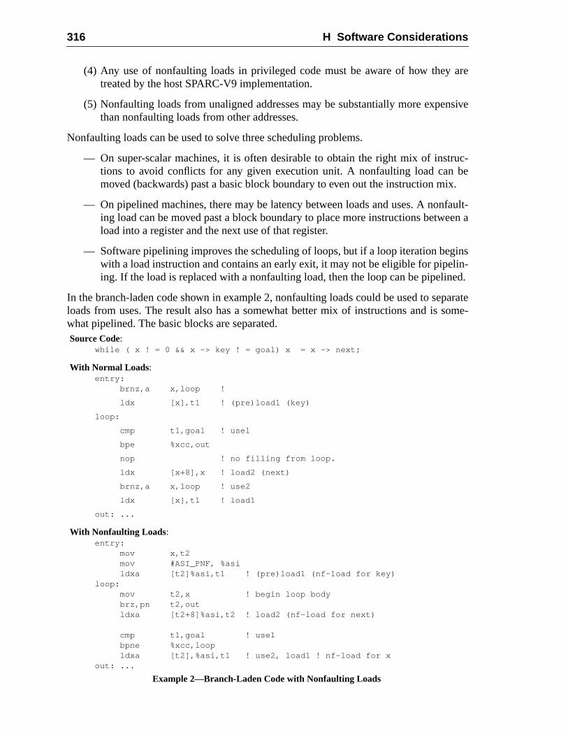
316 H Software Considerations
are
nsive
ruc-beix.
fault-een a
inslin-ned.
paratesome-
(4) Any use of nonfaulting loads in privileged code must be aware of how theytreated by the host SPARC-V9 implementation.
(5) Nonfaulting loads from unaligned addresses may be substantially more expethan nonfaulting loads from other addresses.
Nonfaulting loads can be used to solve three scheduling problems.
— On super-scalar machines, it is often desirable to obtain the right mix of insttions to avoid conflicts for any given execution unit. A nonfaulting load canmoved (backwards) past a basic block boundary to even out the instruction m
— On pipelined machines, there may be latency between loads and uses. A noning load can be moved past a block boundary to place more instructions betwload into a register and the next use of that register.
— Software pipelining improves the scheduling of loops, but if a loop iteration begwith a load instruction and contains an early exit, it may not be eligible for pipeing. If the load is replaced with a nonfaulting load, then the loop can be pipeli
In the branch-laden code shown in example 2, nonfaulting loads could be used to seloads from uses. The result also has a somewhat better mix of instructions and iswhat pipelined. The basic blocks are separated.Source Code:
while ( x ! = 0 && x -> key ! = goal) x = x -> next;
With Normal Loads:entry:
brnz,a x,loop !
ldx [x],t1 ! (pre)load1 (key)
loop:
cmp t1,goal ! use1
bpe %xcc,out
nop ! no filling from loop.
ldx [x+8],x ! load2 (next)
brnz,a x,loop ! use2
ldx [x],t1 ! load1
out: ...
With Nonfaulting Loads:entry:
mov x,t2mov #ASI_PNF, %asildxa [t2]%asi,t1 ! (pre)load1 (nf-load for key)
loop:mov t2,x ! begin loop bodybrz,pn t2,outldxa [t2+8]%asi,t2 ! load2 (nf-load for next)
cmp t1,goal ! use1bpne %xcc,loopldxa [t2],%asi,t1 ! use2, load1 ! nf-load for x
out: ...
Example 2—Branch-Laden Code with Nonfaulting Loads
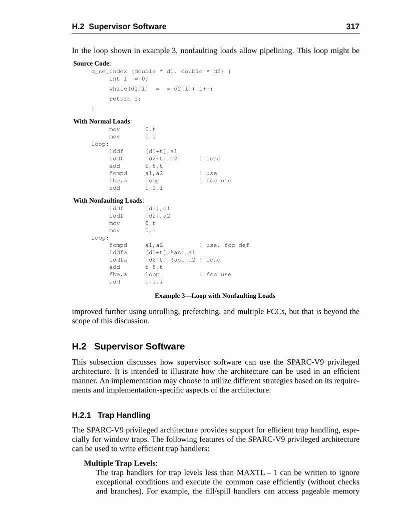
H.2 Supervisor Software 317
be
the
ilegedcientuire-
spe-ure
oreecksmory
In the loop shown in example 3, nonfaulting loads allow pipelining. This loop might
improved further using unrolling, prefetching, and multiple FCCs, but that is beyondscope of this discussion.
H.2 Supervisor Software
This subsection discusses how supervisor software can use the SPARC-V9 privarchitecture. It is intended to illustrate how the architecture can be used in an effimanner. An implementation may choose to utilize different strategies based on its reqments and implementation-specific aspects of the architecture.
H.2.1 Trap Handling
The SPARC-V9 privileged architecture provides support for efficient trap handling, ecially for window traps. The following features of the SPARC-V9 privileged architectcan be used to write efficient trap handlers:
Multiple Trap Levels :The trap handlers for trap levels less than MAXTL – 1 can be written to ignexceptional conditions and execute the common case efficiently (without chand branches). For example, the fill/spill handlers can access pageable me
Example 3—Loop with Nonfaulting Loads
Source Code:d_ne_index (double * d1, double * d2) {
int i = 0;
while(d1[i] = = d2[i]) i++;
return i;
}
With Normal Loads:mov 0,tmov 0,i
loop:lddf [d1+t],a1lddf [d2+t],a2 ! loadadd t,8,tfcmpd a1,a2 ! usefbe,a loop ! fcc useadd i,1,i
With Nonfaulting Loads:lddf [d1],a1lddf [d2],a2mov 8,tmov 0,i
loop:fcmpd a1,a2 ! use, fcc deflddfa [d1+t],%asi,a1lddfa [d2+t],%asi,a2 ! loadadd t,8,tfbe,a loop ! fcc useadd i,1,i
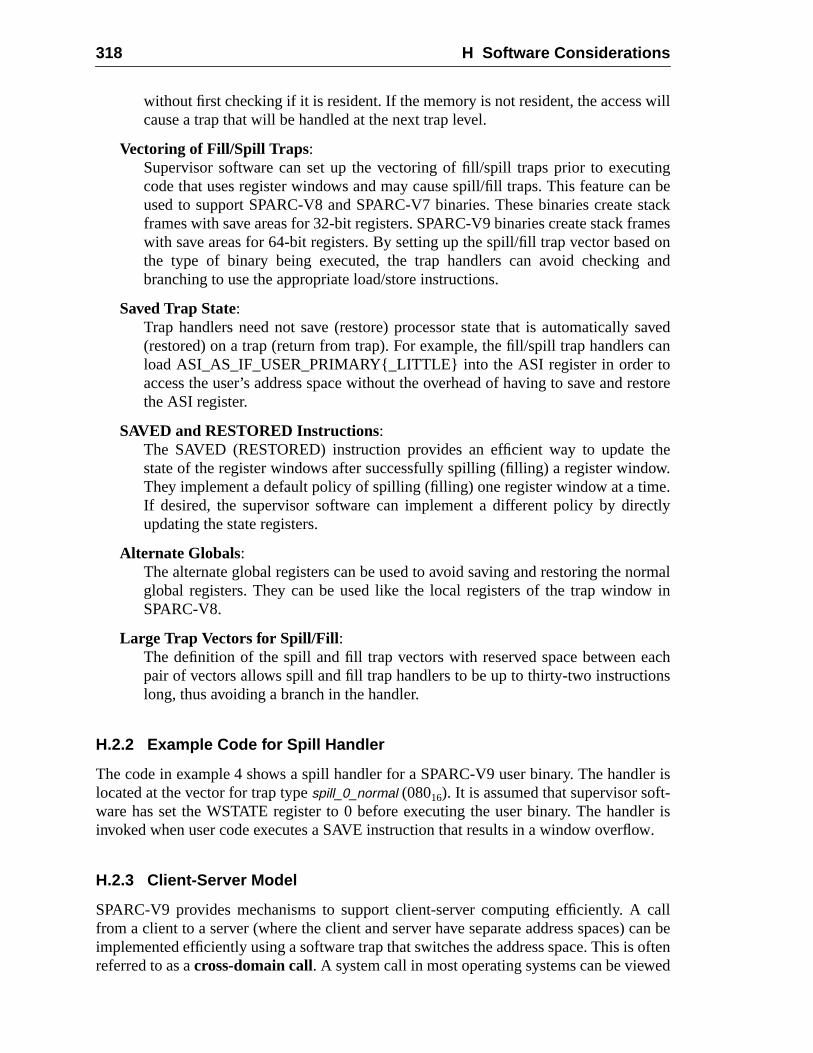
318 H Software Considerations
will
tingn be
stackamesd on
and
savedcan
restore
theow.e.ctly
ormalw in
achns
ler ist-ler is
ow.
callcan beoften
ed
without first checking if it is resident. If the memory is not resident, the accesscause a trap that will be handled at the next trap level.
Vectoring of Fill/Spill Traps :Supervisor software can set up the vectoring of fill/spill traps prior to execucode that uses register windows and may cause spill/fill traps. This feature caused to support SPARC-V8 and SPARC-V7 binaries. These binaries createframes with save areas for 32-bit registers. SPARC-V9 binaries create stack frwith save areas for 64-bit registers. By setting up the spill/fill trap vector basethe type of binary being executed, the trap handlers can avoid checkingbranching to use the appropriate load/store instructions.
Saved Trap State:Trap handlers need not save (restore) processor state that is automatically(restored) on a trap (return from trap). For example, the fill/spill trap handlersload ASI_AS_IF_USER_PRIMARY{_LITTLE} into the ASI register in order toaccess the user’s address space without the overhead of having to save andthe ASI register.
SAVED and RESTORED Instructions:The SAVED (RESTORED) instruction provides an efficient way to updatestate of the register windows after successfully spilling (filling) a register windThey implement a default policy of spilling (filling) one register window at a timIf desired, the supervisor software can implement a different policy by direupdating the state registers.
Alternate Globals:The alternate global registers can be used to avoid saving and restoring the nglobal registers. They can be used like the local registers of the trap windoSPARC-V8.
Large Trap Vectors for Spill/Fill :The definition of the spill and fill trap vectors with reserved space between epair of vectors allows spill and fill trap handlers to be up to thirty-two instructiolong, thus avoiding a branch in the handler.
H.2.2 Example Code for Spill Handler
The code in example 4 shows a spill handler for a SPARC-V9 user binary. The handlocated at the vector for trap typespill_0_normal (08016). It is assumed that supervisor sofware has set the WSTATE register to 0 before executing the user binary. The handinvoked when user code executes a SAVE instruction that results in a window overfl
H.2.3 Client-Server Model
SPARC-V9 provides mechanisms to support client-server computing efficiently. Afrom a client to a server (where the client and server have separate address spaces)implemented efficiently using a software trap that switches the address space. This isreferred to as across-domain call. A system call in most operating systems can be view
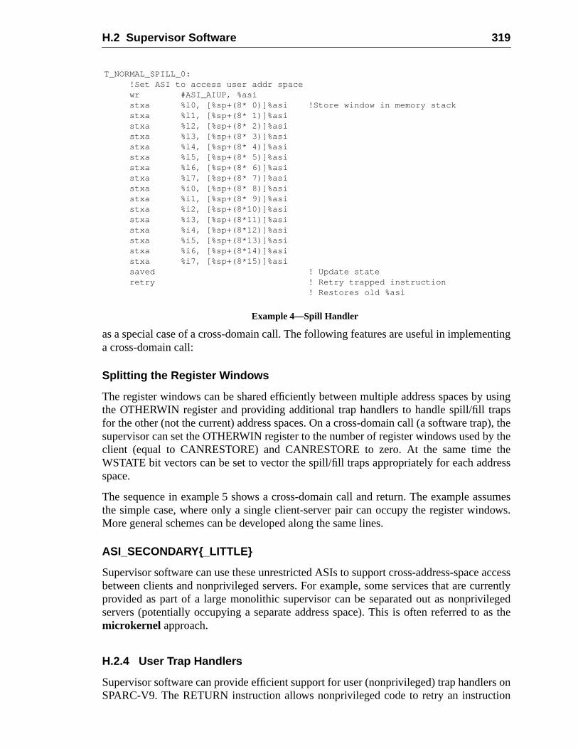
H.2 Supervisor Software 319
nting
usingapsp), they thetheress
sumesows.
accessrrentlyilegedas the
rs ontion
as a special case of a cross-domain call. The following features are useful in implemea cross-domain call:
Splitting the Register Windows
The register windows can be shared efficiently between multiple address spaces bythe OTHERWIN register and providing additional trap handlers to handle spill/fill trfor the other (not the current) address spaces. On a cross-domain call (a software trasupervisor can set the OTHERWIN register to the number of register windows used bclient (equal to CANRESTORE) and CANRESTORE to zero. At the same timeWSTATE bit vectors can be set to vector the spill/fill traps appropriately for each addspace.
The sequence in example 5 shows a cross-domain call and return. The example asthe simple case, where only a single client-server pair can occupy the register windMore general schemes can be developed along the same lines.
ASI_SECONDARY{_LITTLE}
Supervisor software can use these unrestricted ASIs to support cross-address-spacebetween clients and nonprivileged servers. For example, some services that are cuprovided as part of a large monolithic supervisor can be separated out as nonprivservers (potentially occupying a separate address space). This is often referred tomicrokernel approach.
H.2.4 User Trap Handlers
Supervisor software can provide efficient support for user (nonprivileged) trap handleSPARC-V9. The RETURN instruction allows nonprivileged code to retry an instruc
T_NORMAL_SPILL_0:!Set ASI to access user addr spacewr #ASI_AIUP, %asistxa %l0, [%sp+(8* 0)]%asi !Store window in memory stackstxa %l1, [%sp+(8* 1)]%asistxa %l2, [%sp+(8* 2)]%asistxa %l3, [%sp+(8* 3)]%asistxa %l4, [%sp+(8* 4)]%asistxa %l5, [%sp+(8* 5)]%asistxa %l6, [%sp+(8* 6)]%asistxa %l7, [%sp+(8* 7)]%asistxa %i0, [%sp+(8* 8)]%asistxa %i1, [%sp+(8* 9)]%asistxa %i2, [%sp+(8*10)]%asistxa %i3, [%sp+(8*11)]%asistxa %i4, [%sp+(8*12)]%asistxa %i5, [%sp+(8*13)]%asistxa %i6, [%sp+(8*14)]%asistxa %i7, [%sp+(8*15)]%asisaved ! Update stateretry ! Retry trapped instruction
! Restores old %asi
Example 4—Spill Handler
320 H Software Considerations
rningre cane) onappedndler
pointed to by the previous stack frame. This provides the semantics required for retufrom a user trap handler without any change in processor state. Supervisor softwainvoke the user trap handler by first creating a new register window (and stack framits behalf and passing the necessary arguments (including the PC and nPC for the trinstruction) in the local registers. The code in example 6 shows how a user trap hamay be invoked and how it returns:
cross_domain_call:save ! create a new register window for the server.. ! Switch to the execution environment for the server;.. ! Save trap state as necessary.
! Set CWP for caller in TSTATErdpr %tstate, %g1rdpr %cwp, %g2bclr TSTATE_CWP, %g1wrpr %g1, %g2, %tstaterdpr %canrestore, %g1wrpr %g0, 0, %canrestorewrpr %g0, %g1, %otherwinrdpr %wstate, %g1sll %g1, 3, %g1 ! Move WSTATE_NORMAL (client’s
! vector)to WSTATE_OTHERor %g1, WSTATE_SERVER, %g1 ! Set WSTATE_NORMAL to the
! vector for the serverwrpr %g0, %g1, %wstate.. ! Load trap state for serverdone ! Execute server code
cross_domain_return:rdpr %otherwin, %g1wrpr %g0, %g1, %canrestorewrpr %g0, 0, %otherwinrdpr %wstate, %g1srl %g1, 3, %g1wrpr %g0, %g1, %wstate ! Reset WSTATE_NORMAL to
! client’s vector.. ! Restore saved trap state as necessary; this includes
! the return PC for the caller.restore ! Go back to the caller’s register window.
! Set CWP for caller in TSTATErdpr %tstate, %g1rdpr %cwp, %g2bclr TSTATE_CWP, %g1wrpr %g1, %g2, %tstate
done ! return to the caller
Example 5—Cross-Domain Call and Return
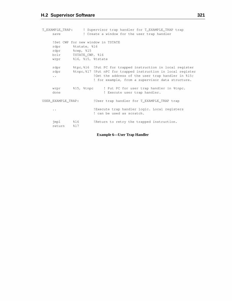
H.2 Supervisor Software 321
T_EXAMPLE_TRAP: ! Supervisor trap handler for T_EXAMPLE_TRAP trapsave ! Create a window for the user trap handler
!Set CWP for new window in TSTATErdpr %tstate, %l6rdpr %cwp, %l5bclr TSTATE_CWP, %l6wrpr %l6, %l5, %tstate
rdpr %tpc,%l6 !Put PC for trapped instruction in local registerrdpr %tnpc,%l7 !Put nPC for trapped instruction in local register.. !Get the address of the user trap handler in %l5;
! for example, from a supervisor data structure.
wrpr %l5, %tnpc ! Put PC for user trap handler in %tnpc.done ! Execute user trap handler.
USER_EXAMPLE_TRAP: !User trap handler for T_EXAMPLE_TRAP trap
.. !Execute trap handler logic. Local registers! can be used as scratch.
jmpl %l6 !Return to retry the trapped instruction.return %l7
Example 6—User Trap Handler

322 H Software Considerations
archi-write
P2)
f thenew
en-eg-tion
or onsubse-stina-
C-ved
I Extending the SPARC-V9 ArchitectureThis appendix describes how extensions can be effectively added to the SPARC-V9tecture. It describes how new instructions can be added through the use of read andancillary state register (ASR) and implementation-dependent (IMPDEP1/IMPDEinstructions.
I.1 Addition of SPARC-V9 Extensions
There are two approved methods of adding extensions to an implementation oSPARC-V9 architecture. An implementor who wishes to define and implement aSPARC-V9 instruction should, if possible, use one of the following methods.
I.1.1 Read/Write Ancillary State Registers (ASRs)
The first method of adding instructions to SPARC-V9 is through the use of the implemtation-dependent Write Ancillary State Register (WRASR) and Read Ancillary State Rister (RDASR) instructions operating on ASRs 16..31. Through a read/write instrucpair, any instruction that requires anrs1, reg_or_imm, andrd field can be implemented. AWRASR instruction can also perform an arbitrary operation on two register sources,one register source and a signed immediate value, and place the result in an ASR. Aquent RDASR instruction can read the result ASR and place its value in an integer detion register.
I.1.2 Implementation-Dependent and Reserved Opcodes
The meaning of “reserved” for SPARC-V9 opcodes differs from its meaning in SPARV8. The SPARC-V9 definition of “reserved” allows implementations to use reser
This appendix is informative only.
It is not part of the SPARC-V9 specification.
Programs that make use of SPARC-V9 architectural extensionsmay not be portable and likely will not conform to any current orfuture SPARC-V9 binary standards.
— WARNING —
323
324 I Extending the SPARC-V9 Architecture
thatpro-tform
s thations.verse
s are
ns incodes
ddede any
tainver-
n for-with
ludesrt forused in
P1,tem-
odes,ughodes
m-ional
opcodes for implementation-specific purposes. While a hardware implementationuses reserved opcodes will be SPARC-V9-compliant, SPARC-V9 ABI-compliantgrams cannot use these reserved opcodes and remain compliant. A SPARC-V9 plathat implements instructions using reserved opcodes must provide software librarieprovide the interface between SPARC-V9 ABI-compliant programs and these instructGraphics libraries provide a good example of this. Hardware platforms have many diimplementations of graphics acceleration hardware, but graphics application programinsulated from this diversity through libraries.
There is no guarantee that a reserved opcode will not be used for additional instructioa future version of the SPARC architecture. Implementors who use reserved opshould keep this in mind.
In some cases forward compatibility may not be an issue; for example, in an embeapplication, binary compatibility may not be an issue. These implementations can usreserved opcodes for extensions.
Even when forward compatibility is an issue, future SPARC revisions are likely to confew changes to opcode assignments, given that backward compatibility with previoussions must be maintained. It is recommended that implementations wishing to remaiward-compatible use the new IMPDEP1 and IMPDEP2 reserved opcodesop3[5:0] = 11 01102 and 11 01112.
V8 Compatibility Note:IMPDEP1 and IMPDEP2 replace the SPARC-V8 CPop1 and CPop2 opcodes. SPARC-V9 incneither the SPARC-V8 coprocessor opcodes nor any other SPARC-V8 architectural suppocoprocessors. The coprocessor opcodes were eliminated because they have not beenSPARC-V7 and SPARC-V8, as witnessed by the lack of coprocessor implementations.
It is further recommended that SPARC International be notified of any use of IMPDEIMPDEP2, or other reserved opcodes. When and if future revisions to SPARC are conplated, and if any SPARC-V9 implementations have made use of reserved opcSPARC International will make every effort not to use those opcodes. By going throSPARC International, there can be feedback and coordination in the choice of opcthat maximizes the probability of forward compatibility. Given the historically small nuber of implementation-specific changes, coordinating through SPARC Internatshould be sufficient to ensure future compatibility.
tui-eteod-spe-SO,
therittendel isr theel to/truc-ct totron-
oryints
TUB,to a
UB,e into
ere thet stillbsec-t notngle
J Programming With the Memory ModelsThis appendix describes how to program with the SPARC-V9 memory models. An intive description of the models is provided in Chapter 8, “Memory Models.” A complformal specification appears in Appendix D, “Formal Specification of the Memory Mels.” In this subsection, general programming guidelines are given first, followed bycific examples showing how low-level synchronization can be implemented in TSO, Pand RMO.
Note that code written for a weaker memory model will execute correctly in any ofstronger memory models. Furthermore, the only possible difference between code wfor a weaker memory model and the corresponding code for a stronger memory mothe presence of memory ordering instructions (MEMBARs) that are not needed fostronger memory model. Hence, transforming code from/to a stronger memory modfrom a weaker memory model means adding/removing certain memory ordering instions.1 The required memory ordering directives are monotonically ordered with respethe strength of the memory model, with the weakest memory model requiring the sgest memory ordering instructions.
The code examples given below are written to run correctly using the RMO memmodel. The comments on the MEMBAR instructions indicate which ordering constra(if any) are required for the PSO and TSO memory models.
J.1 Memory Operations
Programs access memory via five types of operations, namely, load, store, LDSSWAP, and compare-and-swap. Load copies a value from memory or an I/O locationregister. Store copies a value from a register into memory or an I/O location. LDSTSWAP, and compare-and-swap are atomic load-store instructions that store a valu
1. MEMBAR instructions specify seven independent ordering constraints; thus, there are cases whtransition to a stronger memory model allows the use of a less restrictive MEMBAR instruction, burequires a MEMBAR instruction. To demonstrate this property, the code examples given in this sution use multiple MEMBAR instructions if some of the ordering constraints are needed in some buall memory models. Multiple, adjacent MEMBAR instructions can always be replaced with a siMEMBAR instruction byORing the arguments.
This appendix is informative only.
It is not part of the SPARC-V9 specification.
325
326 J Programming With the Memory Models
theessed
value
le, ai-
are exe-SOer in
zingsbytem.
r anyninguse
weak-efer-, PSO
e has
highsyn-
ntage
icallyads iswitchicationa pro-
moryte that
memory or an I/O location and return the old value in a register. The value written byatomic instructions depends on the instruction. LDSTUB stores all ones in the accbyte, SWAP stores the supplied value, and compare-and-swap stores the suppliedonly if the old value equals the second supplied value.
Memory order and consistency are controlled by MEMBAR instructions. For exampMEMBAR #StoreStore (equivalent to a STBAR in SPARC-V8) ensures that all prevous stores have been performed before subsequent stores and atomic load-storescuted by memory. This particular memory order is guaranteed implicitly in TSO, but Pand RMO require this instruction if the correctness of a program depends on the ordwhich two store instructions can be observed by another processor.2
FLUSH is not a memory operation, but it is relevant here in the context of synchronistores with instruction execution. When a processor modifies an instruction at addresA, itdoes a store toA followed by a FLUSHA. The FLUSH ensures that the change madethe store will become visible to the instruction fetch units of all processors in the sys
J.2 Memory Model Selection
Given that all SPARC-V9 systems are required to support TSO, programs written fomemory model will be able to run on any SPARC-V9 system. However, a system runwith the TSO model generally will offer lower performance than PSO or RMO, becaless concurrency is exposed to the CPU and the memory system. The motivation forening the memory model is to allow the CPU to issue multiple, concurrent memory rences in order to hide memory latency and increase access bandwidth. For exampleand RMO allow the CPU to initiate new store operations before an outstanding storcompleted.
Using a weaker memory model for an MP (multiprocessor) application that exhibits adegree of read-write memory sharing with fine granularity and a high frequency ofchronization operations may result in frequent MEMBAR instructions.
In general, it is expected that the weaker memory models offer a performance advafor multiprocessor SPARC-V9 implementations.
J.3 Processors and Processes
In the SPARC-V9 memory models, the term “processor” may be replaced systematby the term “process” or “thread,” as long as the code for switching processes or threwritten properly. The correct process-switch sequence is given in J.8, “Process SSequence.” If an operating system implements this process-switch sequence, applprogrammers may completely ignore the difference between a process/thread andcessor.
2. Memory order is of concern only to programs containing multiple threads that share writable meand that may run on multiple processors, and to those programs which reference I/O locations. Nofrom the processor’s point of view, I/O devices behave like other processors.
J.4 Higher-Level Programming Languages and Memory Models 327
ecialin aeringin a
for
o notenden-ency
eads.ed bye notn use
con-mory
chro-vant to
thes not
tedged,
eas-
read-lockonu-
Do-
rent
J.4 Higher-Level Programming Languages and Memory Models
The SPARC-V9 memory models are defined at the machine instruction level. Spattention is required to write the critical parts of MP/MT (multi-threaded) applicationshigher-level language. Current higher-level languages do not support memory ordinstructions and atomic operations. As a result, MP/MT applications that are writtenhigher-level language generally will rely on a library of MP/MT support functions,example, theparmacslibrary from Argonne National Laboratory.3 The details of con-structing and using such libraries are beyond the scope of this document.
Compiler optimizations such as code motion and instruction scheduling generally dpreserve the order in which memory is accessed but they do preserve the data depcies of a single thread. Compilers do not, in general, deal with the additional dependrequirements to support sharing read-write data among multiple concurrent thrHence, the memory semantics of a SPARC-V9 system in general are not preservoptimizing compilers. For this reason, and because memory ordering directives aravailable from higher-level languages, the examples presented in this subsectioassembly language.
Future compilers may have the ability to present the programmer with a sequentiallysistent memory model despite the underlying hardware’s providing a weaker memodel.4
J.5 Portability And Recommended Programming Style
Whether a program is portable across various memory models depends on how it synnizes access to shared read-write data. Two aspects of a program’s style are releportability:
— Good semanticsrefers to whether the synchronization primitives chosen andway in which they are used are such that changing the memory model doeinvolve making any changes to the code that uses the primitives.
— Good structure refers to whether the code for synchronization is encapsulathrough the use of primitives such that when the memory model is chanrequired changes to the code are confined to the primitives.
Good semantics are a prerequisite for portability, while good structure makes portingier.
Programs that use single-writer/multiple-reader locks to protect all access to sharedwrite data are portable across all memory models. The code that implements theprimitives themselves is portable across all models only if it is written to run correctlyRMO. If the lock primitives are collected into a library, then, at worst, only the library ro
3. Lusk, E. L., R.A. Overbeek, “Use of Monitors in Fortran: A Tutorial on the Barrier, Self-schedulingLoop, and Askfor Monitors,” TR# ANL-84-51, Argonne National Laboratory, June 1987.
4. See Gharachorloo, K., S.V. Adve, A. Gupta, J.L. Hennessy, and M.D. Hill, “Programming for DiffeMemory Consistency Models,” Journal of Parallel and Distributed Systems, 15:4, August 1992.
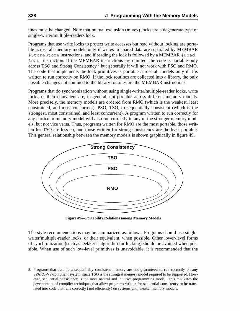
328 J Programming With the Memory Models
ype of
porta-BAR
nly
it isnly
ritedels.leastis thely forod-writ-
rtable.49.
ingle-rmspos-t the
on any. How-s the
trans-
tines must be changed. Note that mutual exclusion (mutex) locks are a degenerate tsingle-writer/multiple-readers lock.
Programs that use write locks to protect write accesses but read without locking areble across all memory models only if writes to shared data are separated by MEM#StoreStore instructions, and if reading the lock is followed by a MEMBAR#Load-Load instruction. If the MEMBAR instructions are omitted, the code is portable oacross TSO and Strong Consistency,5 but generally it will not work with PSO and RMO.The code that implements the lock primitives is portable across all models only ifwritten to run correctly on RMO. If the lock routines are collected into a library, the opossible changes not confined to the library routines are the MEMBAR instructions.
Programs that do synchronization without using single-writer/multiple-reader locks, wlocks, or their equivalent are, in general, not portable across different memory moMore precisely, the memory models are ordered from RMO (which is the weakest,constrained, and most concurrent), PSO, TSO, to sequentially consistent (whichstrongest, most constrained, and least concurrent). A program written to run correctany particular memory model will also run correctly in any of the stronger memory mels, but not vice versa. Thus, programs written for RMO are the most portable, thoseten for TSO are less so, and those written for strong consistency are the least poThis general relationship between the memory models is shown graphically in figure
Figure 49—Portability Relations among Memory Models
The style recommendations may be summarized as follows: Programs should use swriter/multiple-reader locks, or their equivalent, when possible. Other lower-level foof synchronization (such as Dekker’s algorithm for locking) should be avoided whensible. When use of such low-level primitives is unavoidable, it is recommended tha
5. Programs that assume a sequentially consistent memory are not guaranteed to run correctlySPARC-V9-compliant system, since TSO is the strongest memory model required to be supportedever, sequential consistency is the most natural and intuitive programming model. This motivatedevelopment of compiler techniques that allow programs written for sequential consistency to belated into code that runs correctly (and efficiently) on systems with weaker memory models.
Strong Consistency
TSO
PSO
RMO
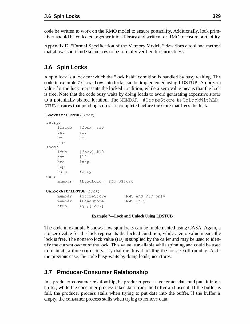
J.6 Spin Locks 329
m-ility.
hod
hezerolock
stores
.
in, as the
iden-sedin
it into afer isr is
code be written to work on the RMO model to ensure portability. Additionally, lock priitives should be collected together into a library and written for RMO to ensure portab
Appendix D, “Formal Specification of the Memory Models,” describes a tool and metthat allows short code sequences to be formally verified for correctness.
J.6 Spin Locks
A spin lock is a lock for which the “lock held” condition is handled by busy waiting. Tcode in example 7 shows how spin locks can be implemented using LDSTUB. A nonvalue for the lock represents the locked condition, while a zero value means that theis free. Note that the code busy waits by doing loads to avoid generating expensiveto a potentially shared location. TheMEMBAR #StoreStore in UnLockWithLD-STUB ensures that pending stores are completed before the store that frees the lock
The code in example 8 shows how spin locks can be implemented using CASA. Aganonzero value for the lock represents the locked condition, while a zero value meanlock is free. The nonzero lock value (ID) is supplied by the caller and may be used totify the current owner of the lock. This value is available while spinning and could be uto maintain a time-out or to verify that the thread holding the lock is still running. Asthe previous case, the code busy-waits by doing loads, not stores.
J.7 Producer-Consumer Relationship
In a producer-consumer relationship,the producer process generates data and putsbuffer, while the consumer process takes data from the buffer and uses it. If the buffull, the producer process stalls when trying to put data into the buffer. If the buffeempty, the consumer process stalls when trying to remove data.
LockWithLDSTUB ( lock )
retry:ldstub [ lock ],%l0tst %l0be outnop
loop:ldub [ lock ],%l0tst %l0bne loopnopba,a retry
out:membar #LoadLoad | #LoadStore
UnLockWithLDSTUB ( lock )membar #StoreStore !RMO and PSO onlymembar #LoadStore !RMO onlystub %g0,[ lock ]
Example 7—Lock and Unlock Using LDSTUB
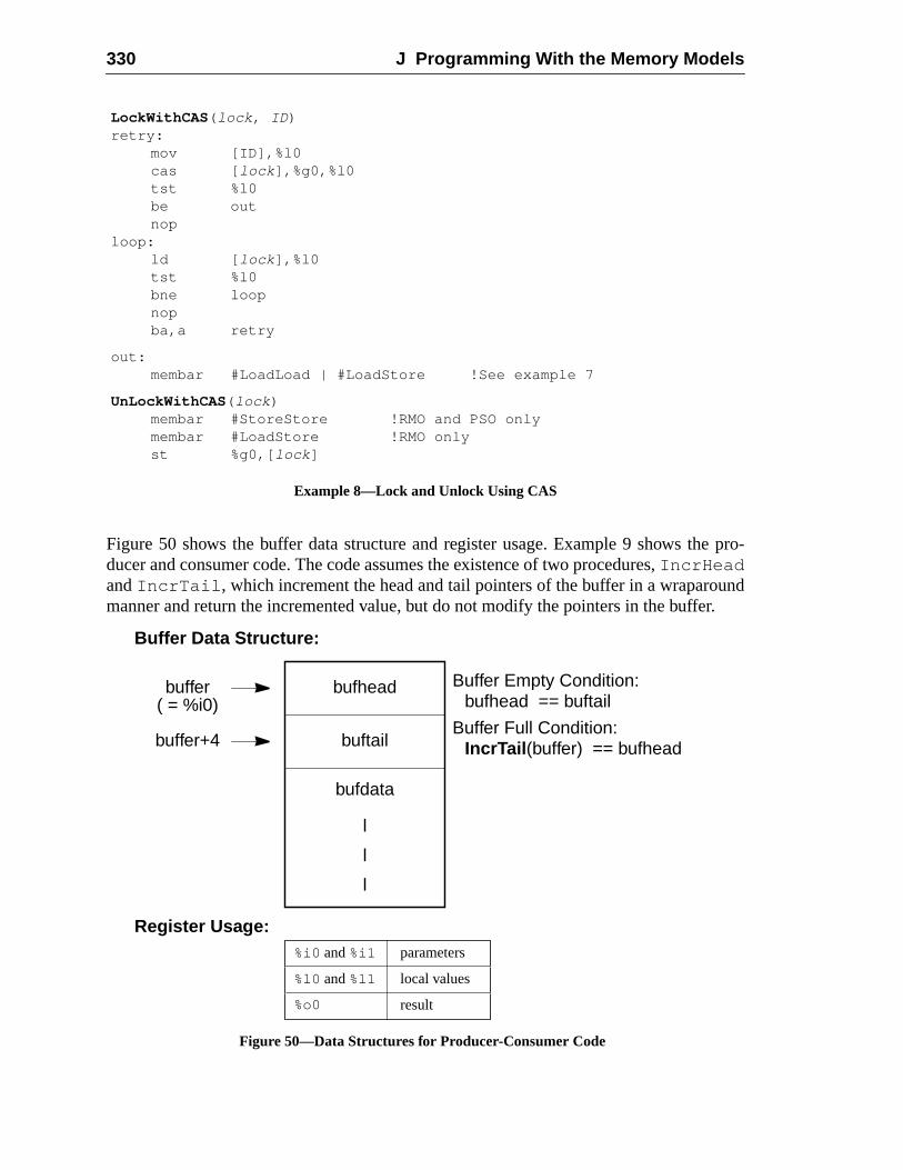
330 J Programming With the Memory Models
e pro-
undr.
Figure 50 shows the buffer data structure and register usage. Example 9 shows thducer and consumer code. The code assumes the existence of two procedures,IncrHeadandIncrTail , which increment the head and tail pointers of the buffer in a wraparomanner and return the incremented value, but do not modify the pointers in the buffe
LockWithCAS ( lock , ID )retry:
mov [ID],%l0cas [ lock ],%g0,%l0tst %l0be outnop
loop:ld [ lock ],%l0tst %l0bne loopnopba,a retry
out:membar #LoadLoad | #LoadStore !See example 7
UnLockWithCAS ( lock )membar #StoreStore !RMO and PSO onlymembar #LoadStore !RMO onlyst %g0,[ lock ]
Example 8—Lock and Unlock Using CAS
bufhead
buftail
bufdata
l
l
l
buffer Buffer Empty Condition:bufhead == buftail
Buffer Full Condition:IncrTail (buffer) == bufheadbuffer+4
( = %i0)
Buffer Data Structure:
Register Usage:%i0 and%i1
%o0
%l0 and%l1
parameters
local values
result
Figure 50—Data Structures for Producer-Consumer Code
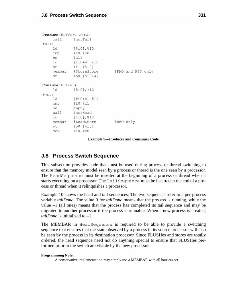
J.8 Process Switch Sequence 331
ing tocessor.n it-
processeay be
reated,
gwill alsototallys per-
J.8 Process Switch Sequence
This subsection provides code that must be used during process or thread switchensure that the memory model seen by a process or thread is the one seen by a proThe HeadSequence must be inserted at the beginning of a process or thread whestarts executing on a processor. TheTailSequence must be inserted at the end of a process or thread when it relinquishes a processor.
Example 10 shows the head and tail sequences. The two sequences refer to a per-variabletailDone. The value 0 fortailDone means that the process is running, while thvalue –1 (all ones) means that the process has completed its tail sequence and mmigrated to another processor if the process is runnable. When a new process is ctailDone is initialized to –1.
The MEMBAR in HeadSequence is required to be able to provide a switchinsequence that ensures that the state observed by a process in its source processorbe seen by the process in its destination processor. Since FLUSHes and stores areordered, the head sequence need not do anything special to ensure that FLUSHeformed prior to the switch are visible by the new processor.
Programming Note:A conservative implementation may simply use a MEMBAR with all barriers set.
Produce ( buffer , data )call IncrTail
full:ld [%i0],%l0cmp %l0,%o0be fullld [%i0+4],%l0st %i1,[%l0]membar #StoreStore !RMO and PSO onlyst %o0,[%i0+4]
Consume( buffer )ld [%i0],%l0
empty:ld [%i0+4],%l1cmp %l0,%l1be emptycall IncrHeadld [%l0],%l0membar #LoadStore !RMO onlyst %o0,[%i0]mov %l0,%o0
Example 9—Producer and Consumer Code
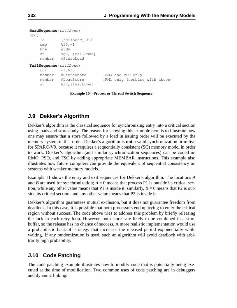
332 J Programming With the Memory Models
ctionhow
y the
orderd onalsoy on
nsec-
fromriticalasingtoreld usewhilerbi-
exe-gers
J.9 Dekker’s Algorithm
Dekker’s algorithm is the classical sequence for synchronizing entry into a critical seusing loads and stores only. The reason for showing this example here is to illustrateone may ensure that a store followed by a load in issuing order will be executed bmemory system in that order. Dekker’s algorithm isnot a valid synchronization primitivefor SPARC-V9, because it requires a sequentially consistent (SC) memory model into work. Dekker’s algorithm (and similar synchronization sequences) can be codeRMO, PSO, and TSO by adding appropriate MEMBAR instructions. This exampleillustrates how future compilers can provide the equivalent of sequential consistencsystems with weaker memory models.
Example 11 shows the entry and exit sequences for Dekker’s algorithm. The locatioAandB are used for synchronization;A = 0 means that process P1 is outside its critical stion, while any other value means that P1 is inside it; similarly,B = 0 means that P2 is out-side its critical section, and any other value means that P2 is inside it.
Dekker’s algorithm guarantees mutual exclusion, but it does not guarantee freedomdeadlock. In this case, it is possible that both processors end up trying to enter the cregion without success. The code above tries to address this problem by briefly relethe lock in each retry loop. However, both stores are likely to be combined in a sbuffer, so the release has no chance of success. A more realistic implementation woua probabilistic back-off strategy that increases the released period exponentiallywaiting. If any randomization is used, such an algorithm will avoid deadlock with atrarily high probability.
J.10 Code Patching
The code patching example illustrates how to modify code that is potentially beingcuted at the time of modification. Two common uses of code patching are in debugand dynamic linking.
HeadSequence ( tailDone )nrdy:
ld [ tailDone ],%l0cmp %l0,-1bne nrdyst %g0, [ tailDone ]membar #StoreLoad
TailSequence ( tailDone )mov -1,%l0membar #StoreStore !RMO and PSO onlymembar #LoadStore !RMO only (combine with above)st %l0,[ tailDone ]
Example 10—Process or Thread Switch Sequence
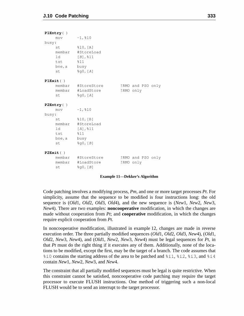
J.10 Code Patching 333
old
e
verse
ca-es that
hentargetlocal
Code patching involves a modifying process,Pm, and one or more target processesPt. Forsimplicity, assume that the sequence to be modified is four instructions long: thesequence is (Old1, Old2, Old3, Old4), and the new sequence is (New1, New2, New3,New4). There are two examples:noncooperativemodification, in which the changes armade without cooperation fromPt; andcooperativemodification, in which the changesrequire explicit cooperation fromPt.
In noncooperative modification, illustrated in example 12, changes are made in reexecution order. The three partially modified sequences (Old1, Old2, Old3, New4), (Old1,Old2, New3, New4), and (Old1, New2, New3, New4) must be legal sequences forPt, inthatPt must do the right thing if it executes any of them. Additionally, none of the lotions to be modified, except the first, may be the target of a branch. The code assum%i0 contains the starting address of the area to be patched and%i1 , %i2 , %i3 , and%i4containNew1, New2, New3, andNew4.
The constraint that all partially modified sequences must be legal is quite restrictive. Wthis constraint cannot be satisfied, noncooperative code patching may require theprocessor to execute FLUSH instructions. One method of triggering such a non-FLUSH would be to send an interrupt to the target processor.
P1Entry ( )mov -1,%l0
busy:st %l0,[A]membar #StoreLoadld [ B],%l1tst %l1bne,a busyst %g0,[ A]
P1Exit ( )membar #StoreStore !RMO and PSO onlymembar #LoadStore !RMO onlyst %g0,[ A]
P2Entry ( )mov -1,%l0
busy:st %l0,[B]membar #StoreLoadld [ A],%l1tst %l1bne,a busyst %g0,[ B]
P2Exit ( )membar #StoreStore !RMO and PSO onlymembar #LoadStore !RMO onlyst %g0,[ B]
Example 11—Dekker’s Algorithm
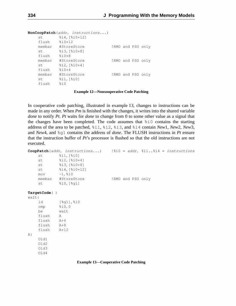
334 J Programming With the Memory Models
n beblehat
not
In cooperative code patching, illustrated in example 13, changes to instructions camade in any order. WhenPmis finished with the changes, it writes into the shared variadoneto notify Pt. Pt waits fordoneto change from 0 to some other value as a signal tthe changes have been completed. The code assumes that%i0 contains the startingaddress of the area to be patched,%i1 , %i2 , %i3 , and%i4 containNew1, New2, New3,andNew4, and%g1contains the address ofdone. The FLUSH instructions inPt ensurethat the instruction buffer ofPt’s processor is flushed so that the old instructions areexecuted.
NonCoopPatch ( addr , instructions ...)st %i4,[%i0+12]flush %i0+12membar #StoreStore !RMO and PSO onlyst %i3,[%i0+8]flush %i0+8membar #StoreStore !RMO and PSO onlyst %i2,[%i0+4]flush %i0+4membar #StoreStore !RMO and PSO onlyst %i1,[%i0]flush %i0
Example 12—Nonxooperative Code Patching
CoopPatch ( addr , instructions ...) !%i0 = addr , %i1..%i4 = instruction sst %i1,[%i0]st %i2,[%i0+4]st %i3,[%i0+8]st %i4,[%i0+12]mov -1,%l0membar #StoreStore !RMO and PSO onlyst %l0,[%g1]
TargetCode ( )wait:
ld [%g1],%l0cmp %l0,0be waitflush Aflush A+4flush A+8flush A+12
A:Old1Old2Old3Old4
Example 13—Cooperative Code Patching
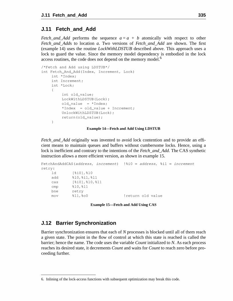
J.11 Fetch_and_Add 335
alock
ffi-sing a
hthe
J.11 Fetch_and_Add
Fetch_and_Addperforms the sequencea = a + b atomically with respect to otherFetch_and_Adds to locationa. Two versions ofFetch_and_Addare shown. The first(example 14) uses the routineLockWithLDSTUBdescribed above. This approach useslock to guard the value. Since the memory model dependency is embodied in theaccess routines, the code does not depend on the memory model.6
Fetch_and_Addoriginally was invented to avoid lock contention and to provide an ecient means to maintain queues and buffers without cumbersome locks. Hence, ulock is inefficient and contrary to the intentions of theFetch_and_Add. The CAS syntheticinstruction allows a more efficient version, as shown in example 15.
J.12 Barrier Synchronization
Barrier synchronization ensures that each ofN processes is blocked until all of them reaca given state. The point in the flow of control at which this state is reached is calledbarrier; hence the name. The code uses the variableCountinitialized toN. As each processreaches its desired state, it decrementsCountand waits forCountto reach zero before pro-ceeding further.
6. Inlining of the lock-access functions with subsequent optimization may break this code.
/*Fetch and Add using LDSTUB*/int Fetch_And_Add(Index, Increment, Lock)
int *Index;int Increment;int *Lock;{
int old_value;LockWithLDSTUB(Lock);old_value = *Index;*Index = old_value + Increment;UnlockWithLDSTUB(Lock);return(old_value);
}
Example 14—Fetch and Add Using LDSTUB
FetchAndAddCAS( address , increment ) !%i0 = address , %i1 = incrementretry:
ld [%i0],%l0add %l0,%i1,%l1cas [%i0],%l0,%l1cmp %l0,%l1bne retrymov %l1,%o0 !return old value
Example 15—Fetch and Add Using CAS
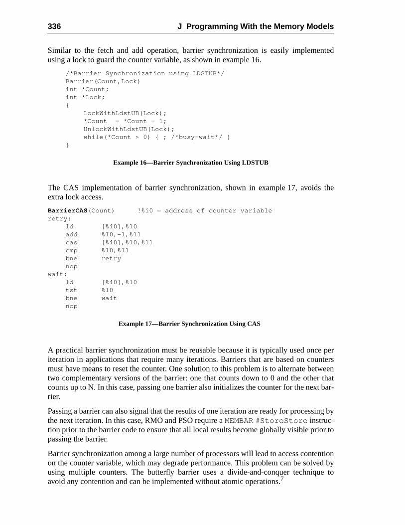
336 J Programming With the Memory Models
nted
the
e pernterstweenr thatt bar-
ing by
or to
ntioned bye to
Similar to the fetch and add operation, barrier synchronization is easily implemeusing a lock to guard the counter variable, as shown in example 16.
The CAS implementation of barrier synchronization, shown in example 17, avoidsextra lock access.
A practical barrier synchronization must be reusable because it is typically used onciteration in applications that require many iterations. Barriers that are based on coumust have means to reset the counter. One solution to this problem is to alternate betwo complementary versions of the barrier: one that counts down to 0 and the othecounts up to N. In this case, passing one barrier also initializes the counter for the nexrier.
Passing a barrier can also signal that the results of one iteration are ready for processthe next iteration. In this case, RMO and PSO require aMEMBAR #StoreStore instruc-tion prior to the barrier code to ensure that all local results become globally visible pripassing the barrier.
Barrier synchronization among a large number of processors will lead to access conteon the counter variable, which may degrade performance. This problem can be solvusing multiple counters. The butterfly barrier uses a divide-and-conquer techniquavoid any contention and can be implemented without atomic operations.7
/*Barrier Synchronization using LDSTUB*/Barrier(Count,Lock)int *Count;int *Lock;{
LockWithLdstUB(Lock);*Count = *Count - 1;UnlockWithLdstUB(Lock);while(*Count > 0) { ; /*busy-wait*/ }
}
Example 16—Barrier Synchronization Using LDSTUB
BarrierCAS (Count) !%i0 = address of counter variableretry:
ld [%i0],%l0add %l0,-1,%l1cas [%i0],%l0,%l1cmp %l0,%l1bne retrynop
wait:ld [%i0],%l0tst %l0bne waitnop
Example 17—Barrier Synchronization Using CAS
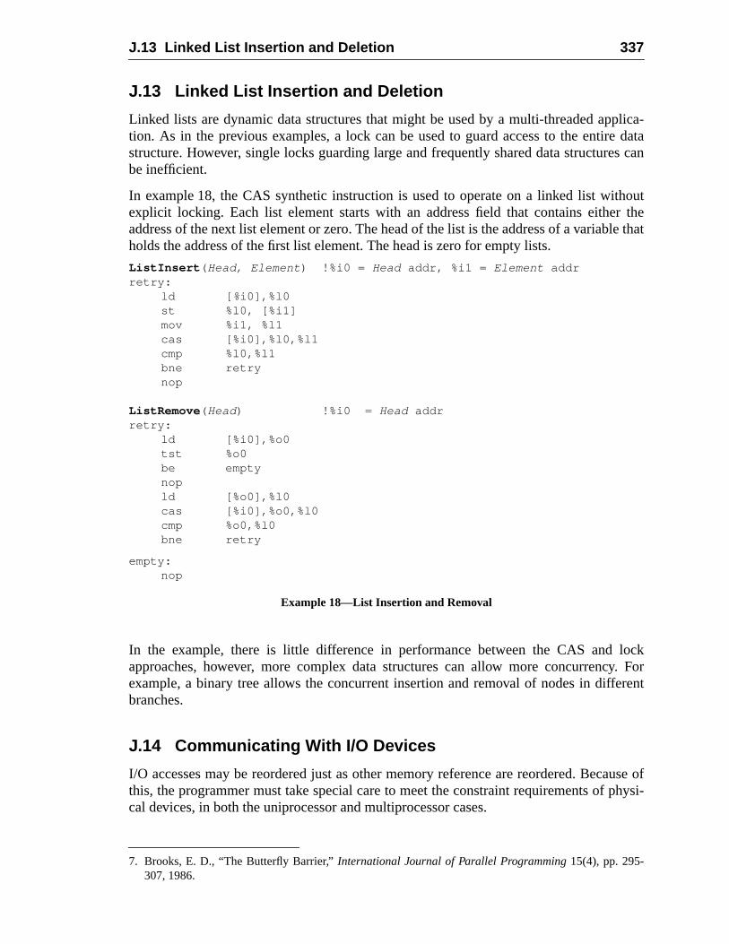
J.13 Linked List Insertion and Deletion 337
plica-e datas can
houtr thele that
locky. Forerent
ause ofphysi-
J.13 Linked List Insertion and Deletion
Linked lists are dynamic data structures that might be used by a multi-threaded aption. As in the previous examples, a lock can be used to guard access to the entirstructure. However, single locks guarding large and frequently shared data structurebe inefficient.
In example 18, the CAS synthetic instruction is used to operate on a linked list witexplicit locking. Each list element starts with an address field that contains eitheaddress of the next list element or zero. The head of the list is the address of a variabholds the address of the first list element. The head is zero for empty lists.
In the example, there is little difference in performance between the CAS andapproaches, however, more complex data structures can allow more concurrencexample, a binary tree allows the concurrent insertion and removal of nodes in diffbranches.
J.14 Communicating With I/O Devices
I/O accesses may be reordered just as other memory reference are reordered. Becthis, the programmer must take special care to meet the constraint requirements ofcal devices, in both the uniprocessor and multiprocessor cases.
7. Brooks, E. D., “The Butterfly Barrier,”International Journal of Parallel Programming15(4), pp. 295-307, 1986.
ListInsert ( Head, Element ) !%i0 = Head addr, %i1 = Element addrretry:
ld [ %i0],%l0st %l0, [%i1]mov %i1, %l1cas [%i0],%l0,%l1cmp %l0,%l1bne retrynop
ListRemove ( Head) !%i0 = Head addrretry:
ld [%i0],%o0tst %o0be emptynopld [%o0],%l0cas [%i0],%o0,%l0cmp %o0,%l0bne retry
empty:nop
Example 18—List Insertion and Removal
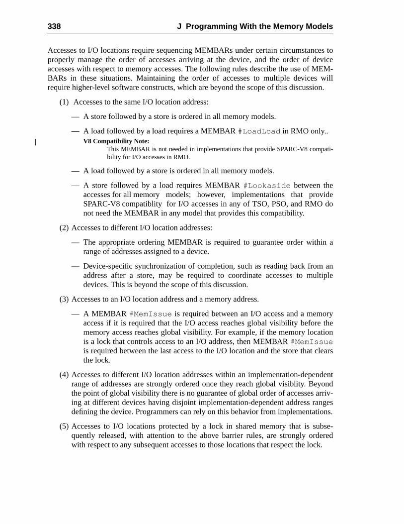
338 J Programming With the Memory Models
es toeviceMEM-will
ion.
ati-
videdo
n a
anltiple
orythe
tion
lears
dentyondrriv-ngesions.
bse-eredock.
Accesses to I/O locations require sequencing MEMBARs under certain circumstancproperly manage the order of accesses arriving at the device, and the order of daccesses with respect to memory accesses. The following rules describe the use ofBARs in these situations. Maintaining the order of accesses to multiple devicesrequire higher-level software constructs, which are beyond the scope of this discuss
(1) Accesses to the same I/O location address:
— A store followed by a store is ordered in all memory models.
— A load followed by a load requires a MEMBAR#LoadLoad in RMO only..V8 Compatibility Note:
This MEMBAR is not needed in implementations that provide SPARC-V8 compbility for I/O accesses in RMO.
— A load followed by a store is ordered in all memory models.
— A store followed by a load requires MEMBAR#Lookaside between theaccesses for all memory models; however, implementations that proSPARC-V8 compatiblity for I/O accesses in any of TSO, PSO, and RMOnot need the MEMBAR in any model that provides this compatibility.
(2) Accesses to different I/O location addresses:
— The appropriate ordering MEMBAR is required to guarantee order withirange of addresses assigned to a device.
— Device-specific synchronization of completion, such as reading back fromaddress after a store, may be required to coordinate accesses to mudevices. This is beyond the scope of this discussion.
(3) Accesses to an I/O location address and a memory address.
— A MEMBAR #MemIssue is required between an I/O access and a memaccess if it is required that the I/O access reaches global visibility beforememory access reaches global visibility. For example, if the memory locais a lock that controls access to an I/O address, then MEMBAR#MemIssueis required between the last access to the I/O location and the store that cthe lock.
(4) Accesses to different I/O location addresses within an implementation-depenrange of addresses are strongly ordered once they reach global visiblity. Bethe point of global visibility there is no guarantee of global order of accesses aing at different devices having disjoint implementation-dependent address radefining the device. Programmers can rely on this behavior from implementat
(5) Accesses to I/O locations protected by a lock in shared memory that is suquently released, with attention to the above barrier rules, are strongly ordwith respect to any subsequent accesses to those locations that respect the l
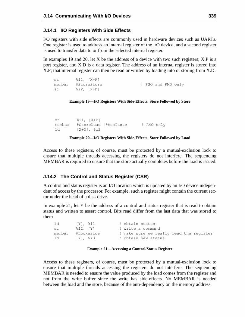
J.14 Communicating With I/O Devices 339
RTs.egister
intoX
ck toencingsued.
pen-nt sec-
btained to
ck toencingr anded
dress.
J.14.1 I/O Registers With Side Effects
I/O registers with side effects are commonly used in hardware devices such as UAOne register is used to address an internal register of the I/O device, and a second ris used to transfer data to or from the selected internal register.
In examples 19 and 20, let X be the address of a device with two such registers; X.P is aport register, and X.D is a data register. The address of an internal register is storedX.P; that internal register can then be read or written by loading into or storing from .D.
Access to these registers, of course, must be protected by a mutual-exclusion loensure that multiple threads accessing the registers do not interfere. The sequMEMBAR is required to ensure that the store actually completes before the load is is
J.14.2 The Control and Status Register (CSR)
A control and status register is an I/O location which is updated by an I/O device indedent of access by the processor. For example, such a register might contain the curretor under the head of a disk drive.
In example 21, let Y be the address of a control and status register that is read to ostatus and written to assert control. Bits read differ from the last data that was storthem.
Access to these registers, of course, must be protected by a mutual-exclusion loensure that multiple threads accessing the registers do not interfere. The sequMEMBAR is needed to ensure the value produced by the load comes from the registenot from the write buffer since the write has side-effects. No MEMBAR is needbetween the load and the store, because of the anti-dependency on the memory ad
st %i1, [X+P]membar #StoreStore ! PSO and RMO onlyst %i2, [X+D]
Example 19—I/O Registers With Side-Effects: Store Followed by Store
st %i1, [X+P]membar #StoreLoad |#MemIssue ! RMO onlyld [X+D], %i2
Example 20—I/O Registers With Side-Effects: Store Followed by Load
ld [Y], %i1 ! obtain statusst %i2, [Y] ! write a commandmembar #Lookaside ! make sure we really read the registerld [Y], %i3 ! obtain new status
Example 21—Accessing a Control/Status Register
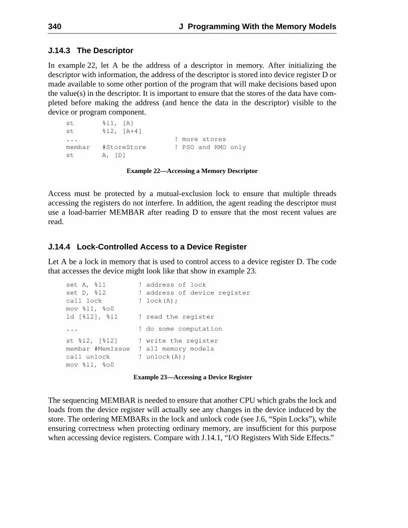
340 J Programming With the Memory Models
theD oruponcom-
to the
eadsr musts are
code
k andy thehileposeects.”
J.14.3 The Descriptor
In example 22, let A be the address of a descriptor in memory. After initializingdescriptor with information, the address of the descriptor is stored into device registermade available to some other portion of the program that will make decisions basedthe value(s) in the descriptor. It is important to ensure that the stores of the data havepleted before making the address (and hence the data in the descriptor) visibledevice or program component.
Access must be protected by a mutual-exclusion lock to ensure that multiple thraccessing the registers do not interfere. In addition, the agent reading the descriptouse a load-barrier MEMBAR after reading D to ensure that the most recent valueread.
J.14.4 Lock-Controlled Access to a Device Register
Let A be a lock in memory that is used to control access to a device register D. Thethat accesses the device might look like that show in example 23.
The sequencing MEMBAR is needed to ensure that another CPU which grabs the locloads from the device register will actually see any changes in the device induced bstore. The ordering MEMBARs in the lock and unlock code (see J.6, “Spin Locks”), wensuring correctness when protecting ordinary memory, are insufficient for this purwhen accessing device registers. Compare with J.14.1, “I/O Registers With Side Eff
st %i1, [A]st %i2, [A+4]... ! more storesmembar #StoreStore ! PSO and RMO onlyst A, [D]
Example 22—Accessing a Memory Descriptor
set A, %l1 ! address of lockset D, %l2 ! address of device registercall lock ! lock(A);mov %l1, %o0ld [%l2], %i1 ! read the register
... ! do some computation
st %i2, [%l2] ! write the registermembar #MemIssue ! all memory modelscall unlock ! unlock(A);mov %l1, %o0
Example 23—Accessing a Device Register
it.
tureatively
trapset, and
lowsed
trapon-vels
CWP
ler,
n-
sor/
resets
K Changes From SPARC-V8 to SPARC-V9SPARC-V9 is complimentary to the SPARC-V8 architecture; it does not replaceSPARC-V9 was designed to be a higher-performance peer to SPARC-V8.
Application software for the 32-bit SPARC-V8 (Version 8) microprocessor architeccan execute, unchanged, on SPARC-V9 systems. SPARC-V8 software executes non SPARC-V9-conformant processors; no special compatibility mode is required.
Changes to the SPARC-V9 architecture since SPARC-V8 are in six main areas: themodel, data formats, the registers, alternate address space access, the instructionthe memory model.
K.1 Trap Model
The trap model, visible only to privileged software, has changed substantially.
— Instead of one level of traps, four or more levels are now supported. This alfirst-level trap handlers, notably register window spill and fill (formerly calloverflow and underflow) traps, to execute much faster. This is because suchhandlers can now execute without costly run-time checks for lower-level trap cditions, such as page faults or a misaligned stack pointer. Also, multiple trap lesupport more robust fault-tolerance mechanisms.
— Most traps no longer change the CWP. Instead, the trap state (including theregister) is saved in register stacks called TSTATE, TT, TPC, and TNPC.
— New instructions (DONE and RETRY) are used to return from a trap handinstead of RETT.
— A new instruction (RETURN) is provided for returning from a trap handler runing in nonprivileged mode, providing support for user trap handlers.
— Terminology about privileged-mode execution has changed, from “superviuser” to “privileged/nonprivileged.”
— A new processor state, RED_state, has been added to facilitate processingand nested traps that would exceed MAXTL.
This appendix is informative only.
It is not part of the SPARC-V9 specification.
341
342 K Changes From SPARC-V8 to SPARC-V9
ontrolecific
ters,
K.2 Data Formats
Data formats for extended (64-bit) integers have been added.
K.3 Little-Endian Support
Data accesses can be either big-endian or little-endian. Bits in the PSTATE register cthe implicit endianness of data accesses. Special ASI values are provided to allow spdata accesses to be in a specific endianness.
K.4 Registers
These privileged SPARC-V8 registers have been deleted:
— PSR: Processor State Register
— TBR: Trap Base Register
— WIM: Window Invalid Mask
These registers have been widened from 32 to 64 bits:
— All integer registers
— All state registers: FSR, PC, nPC, Y
The contents of the following register has changed:
— FSR: Floating-Point State Register:fcc1, fcc2, andfcc3 (additional floating-pointcondition code) bits have been added and the register widened to 64-bits..
These SPARC-V9 registers are fields within a register in SPARC-V8:
— PIL: Processor Interrupt Level register
— CWP: Current Window Pointer register
— TT[MAXTL]: Trap Type register
— TBA: Trap Base Address register
— VER: Version register
— CCR: Condition Codes Register
These registers have been added:
— Sixteen additional double-precision floating-point registers,f[32]..f[62], which arealiased with and overlap eight additional quad-precision floating-point regisf[32]..f[60]
— FPRS: Floating-Point Register State register
— ASI: ASI register
K.5 Alternate Space Access 343
ntedr inrivi-e no
loads
n now
rder.struc-
n foritten
— PSTATE: Processor State register
— TL: Trap Level register
— TPC[MAXTL]: Trap Program Counter register
— TNPC[MAXTL]: Trap Next Program Counter register
— TSTATE[MAXTL]: Trap State register
— TICK: Hardware clock-tick counter
— CANSAVE: Savable windows register
— CANRESTORE: Restorable windows register
— OTHERWIN: Other windows register
— CLEANWIN: Clean windows register
— WSTATE: Window State register
The SPARC-V9 CWP register is incremented during a SAVE instruction and decremeduring a RESTORE instruction. Although this is the opposite of PSR.CWP’s behavioSPARC-V8, the only software it should affect is a few trap handlers that operate in pleged mode, and that must be rewritten for SPARC-V9 anyway. This change will haveffect on nonprivileged software.
K.5 Alternate Space Access
In SPARC-V8, access to all alternate address spaces is privileged. In SPARC-V9,and stores to ASIs 0016..7f16 are privileged; those to ASIs 8016..FF16 are nonprivileged.That is, load- and store-alternate instructions to one-half of the alternate spaces cabe used in user code.
K.6 Little-Endian Byte Order
In SPARC-V8, all instruction and data accesses were performed in big-endian byte oSPARC-V9 supports both big- and little-endian byte orders for data accesses only; intion accesses in SPARC-V9 are always performed using big-endian order.
K.7 Instruction Set
All changes to the instruction set were made such that application software writteSPARC-V8 can run unchanged on a SPARC-V9 processor. Application software wr
344 K Changes From SPARC-V8 to SPARC-V9
4 bit
the
oint
4-biteticcon-
and/
F,
for SPARC-V8 should not even be able to detect that its instructions now process 6values.
The definitions of the following instructions were extended or modified to work with64-bit model:
— FCMP, FCMPE: Floating-Point Compare—can set any of the four floating-pcondition codes
— LDUW, LDUWA(same as “LD, LDA” in SPARC-V8)
— LDFSR, STFSR: Load/Store FSR: only affect low-order 32 bits of FSR
— RDASR/WRASR: Read/Write State Registers: access additional registers
— SAVE/RESTORE
— SETHI
— SRA, SRL, SLL: Shifts: split into 32-bit and 64-bit versions
— Tcc: (was Ticc) operates with either the 32-bit integer condition codes (icc), or the64-bit integer condition codes (xcc)
— All other arithmetic operations now operate on 64-bit operands and produce 6results. Application software written for SPARC-V8 cannot detect that arithmoperations are now 64 bits wide. This is due to retention of the 32-bit integerdition codes (icc), addition of 64-bit integer condition codes (xcc), and the carry-propagation rules of 2’s-complement arithmetic.
The following instructions have been added to provide support for 64-bit operationsor addressing:
— F[sdq]TOx: Convert floating point to 64-bit word
— FxTO[sdq]: Convert 64-bit word to floating point
— FMOV[dq]: Floating-point Move, double and quad
— FNEG[dq]: Floating-point Negate, double and quad
— FABS[dq]: Floating-point Absolute Value, double and quad
— LDDFA, STDFA, LDFA, STFA: Alternate address space forms of LDDF, STDLDF, and STF
— LDSW: Load a signed word
— LDSWA: Load a signed word from an alternate space
— LDX: Load an extended word
— LDXA: Load an extended word from an alternate space
— LDXFSR: Load all 64 bits of the FSR register
— STX: Store an extended word
K.7 Instruction Set 345
rfor-
on
op
— STXA: Store an extended word into an alternate space
— STXFSR: Store all 64 bits of the FSR register
The following instructions have been added to support the new trap model:
— DONE: Return from trap and skip instruction that trapped
— RDPR and WRPR: Read and Write privileged registers
— RESTORED: Adjust state of register windows after RESTORE
— RETRY: Return from trap and reexecute instruction that trapped
— RETURN: Return
— SAVED: Adjust state of register windows after SAVE
— SIR: Signal Monitor (generate Software Initiated Reset)
The following instructions have been added to support implementation of higher-pemance systems:
— BPcc: Branch on integer condition code with prediction
— BPr: Branch on integer register contents with prediction
— CASA, CASXA: Compare and Swap from an alternate space
— FBPfcc: Branch on floating-point condition code with prediction
— FLUSHW: Flush windows
— FMOVcc: Move floating-point register if condition code is satisfied
— FMOVr: Move floating-point register if integer register contents satisfy conditi
— LDQF(A), STQF(A): Load/Store Quad Floating-point (in an alternate space)
— MOVcc: Move integer register if condition code is satisfied
— MOVr: Move integer register if register contents satisfy condition
— MULX: Generic 64-bit multiply
— POPC: Population Count
— PREFETCH, PREFETCHA: Prefetch Data
— SDIVX, UDIVX: Signed and Unsigned 64-bit divide
The definitions of the following instructions have changed:
— IMPDEPn: Implementation-Dependent instructions (replace SPARC-V8 CPinstructions)
The following instruction was added to support memory synchronization:
— MEMBAR: Memory barrier
346 K Changes From SPARC-V8 to SPARC-V9
ich
v-
sepa-
FQ
Thisloads
Hence,sses inrfor-
The following instructions have been deleted:
— Coprocessor loads and stores
— RDTBR and WRTBR: TBR no longer exists. It has been replaced by TBA, whcan be read/written with RDPR/WRPR instructions.
— RDWIM and WRWIM: WIM no longer exists. WIM has been subsumed by seeral register-window state registers.
— RDPSR and WRPSR: PSR no longer exists. It has been replaced by severalrate registers which are read/written with other instructions.
— RETT: Return from trap (replaced by DONE/RETRY).
— STDFQ: Store Double from Floating-point Queue (replaced by the RDPRinstruction).
K.8 Memory Model
SPARC-V9 defines a new memory model called Relaxed Memory Order (RMO).very weak model allows the CPU hardware to schedule memory accesses such asand stores in nearly any order, as long as the program computes the correct answer.the hardware can instantaneously adjust to resource contentions and schedule accethe most efficient order, leading to much faster memory operations and better pemance.
C,”
C
ting
s toca-
S.The
Bibliography
General References
For general information, see the following:
-----. The SPARC Architecture Manual, Version 8, Prentice-Hall, Inc., 1992.
Boney, Joel [1992]. “SPARC Version 9 Points the Way to the Next Generation RISSunWorld, October 1992, pp. 100-105.
Catanzaro, Ben, ed.The SPARC Technical Papers, Springer-Verlag, 1991.
Cmelik, R. F., S. I. Kong, D. R. Ditzel, and E. J. Kelly, “An Analysis of MIPS and SPARInstruction Set Utilization on the SPEC Benchmarks,”Proceedings of the Fourth Interna-tional Symposium on Architectural Support for Programming Languages and OperaSystems, April 8-11, 1991.
Dewar, R. B. K. and M. Smosna.Microprocessors: A Programmer’s View, McGraw-Hill,Inc., 1990.
Ditzel, David R. [1993]. “SPARC Version 9: Adding 64-Bit Addressing and Robustnesan Existing RISC Architecture.” Videotape available from University Video Communitions, P. O. Box 5129, Stanford, CA, 94309.
Garner, R. B. [1988]. “SPARC: The Scalable Processor Architecture,”SunTechnology, vol.1, no. 3, Summer, 1988; also appeared in M. Hall and J. Barry (eds.),The SunTechnologyPapers, Springer-Verlag, 1990, pp. 75-99.
Garner, R. B., A. Agrawal, F. Briggs, E. W. Brown, D. Hough, W. N. Joy, S. Kleiman,Muchnick, M. Namjoo, D. Patterson, J. Pendleton, K. G. Tan, and R. Tuck [1988]. “Scalable Processor Architecture (SPARC),” 33rd Annual IEEE Computer Conference(COMPCON), February, 1988, San Francisco, CA.
Hennessy, J. and D. Patterson.Computer Architecture: A Quantitative Approach, MorganKaufman Publishers, Inc., San Mateo, CA. 1990.
This bibliography is informative only.
It is not part of the SPARC-V9 specification.
347
348 Bibliography
ew
hed
arry
arry
uter,”
ltipro-ated an
inter-
of993
SO
mory
fer-
IEEE Standard for Binary Floating-Point Arithmetic, IEEE Std 754-1985, IEEE, NYork, NY, 1985.
Katevenis, M. [1983]. Reduced Instruction Set Computer Architectures forVLSI, Ph.D.dissertation, Computer Science Div., Univ. of California, Berkeley, 1983; also publisby M.I.T. Press, Cambridge, MA, 1985.
Kleiman, S. and D. Williams [1988]. “SunOS on SPARC,”33rd AnnualIEEEComp. Conf.(COMPCON), February, 1988, San Francisco, CA; also appeared in M. Hall and J. B(eds.),The SunTechnology Papers, Springer-Verlag, 1990, pp. 13-27.
Muchnick, S. [1988]. “Optimizing Compilers for SPARC,”SunTechnology, Summer 1988,pp. 64-71; also appeared in W. Stallings (ed.),Reduced Instruction Set Computers(2ndedition), IEEE Computer Society Press, 1990, pp. 160-173, and in M. Hall and J. B(eds.),The SunTechnology Papers, Springer-Verlag, 1990, pp. 41-68.
Patterson, D. [1985]. “Reduced Instruction Set Computers,”Communications of theACM,vol. 28, no. 1, January, 1985.
Patterson, D., and D. R. Ditzel, “The Case for the Reduced Instruction Set CompComputer Architecture News, vol 8, no. 7, 1980.
Memory Model References
The concept of a memory model has become a significant one as shared memory mucessors are more widely used. The issues are complex and interesting, and have creactive and extensive literature. A partial annotated list of references is as follows:
Collier, W. W.Reasoning About Parallel Architectures, Prentice Hall, 1992.
Provides a mathematical framework for the study of parallel processors and theiraction with memory.
Dill, David, Seungjoon Park, and Andreas G. Nowatzyk, “Formal SpecificationAbstract Memory Models” inResearch on Integrated Systems: Proceedings of the 1Symposium, Ed. Gaetano Borriello and Carl Ebeling, MIT Press, 1993.
Describes an application of software tools to the verification of the TSO and Pmemory models.
Gharachorloo, K., D. Lenoski, J. Laudon, P. Gibbon, A. Gupta, and J. Hennessy. “MeConsistency and Event Ordering in Scalable Shared-Memory Multiprocessors,”Proceed-ings of the 17th Annual International Symposium on Computer Architecture, May 1990,pp. 15-29.
Provides an overview of contemporary research in memory models.
Gharachorloo, K., S. Adve, A. Gupta, J. Hennessy, and M. Hill. “Programming for Difent Memory Consistency Models,”Journal of Parallel and Distributed Processing, 15:4,August 1992.
Prefetching 349
ason
Con-
ting
elaxed
ul-.
mem-
ture
ors,”
em-
em-
rch
ulti-
ges
orort
This paper proposes a new programming model which allows programmers to reabout programs that have not been reduced to sequential consistency.
Gharachorloo, K., A. Gupta, and J. Hennessy, “Performance Evaluation of Memorysistency Models for Shared Memory Multiprocessors,”Proceedings of the 4th Interna-tional Conference on Architectural Support for Programming Languages and OperaSystems, pp. 245-257, ACM, New York, 1991.
This paper discusses the performance benefits that can be obtained when a rmemory model is used in a shared-memory model processor.
Lamport, Leslie. “How to Make a Multiprocessor Computer That Correctly Executes Mtiprocess Programs,” IEEE Transactions on Computers, C-28, 9, September 1979, pp690-691.
Defines sequential consistency and shows how it can be used in simple shared-ory systems.
Reynal, M.Algorithms for Mutual Exclusion, MIT Press, 1986.
Provides an overview of the mutual exclusion problem and the extensive literaassociated with it.
Scheurich, C., and M. Dubois. “Dependency and Hazard Resolution in MultiprocessProceedings of the 14th International Symposium on Computer Architecture, pp. 234-243,IEEE CS Press, Los Alamitos, CA, 1987.
Sindhu, Predeep, Jean-Marc Frailong, and Michel Ceklov. “Formal Specification of Mory Models,” Xerox Palo Alto Research Center Report CSL-91-11, December 1991.
Introduces the formal framework used to define the SPARC-V8 TSO and PSO mory models.
Treiber, R. Kent. “Systems Programming: Coping with Parallelism,” IBM ReseaReport RJ5118 (53162), 1986.
Provides an overview of the operational issues for systems programming in a mprocessing environment.
Prefetching
Callahan, D., K. Kennedy, A. Porterfield. “Software Prefetching,”Proceedings of theFourth International Conference on Architectural Support for Programming Languaand Operating Systems, April 1991, pp. 40-52.
Mowry, T., M. Lam, and A. Gupta. “Design and Evaluation of a Compiler Algorithm fPrefetching.”Proceedings of the Fifth International Conference on Architectural Suppfor Programming Languages and Operating Systems, October 1992, pp. 62-73.

350 Bibliography
-
-
Index
Aa field of instructions, 66, 138, 141, 144, 147,
148, 152ABI, seeSPARC-V9 Application Binary Interface
(ABI)accrued exception (aexc) field of FSR register, 46,
48, 100, 247, 256activation record, seestack frameADD instruction, 137, 301ADDC instruction, 137ADDcc instruction, 137, 223, 301ADDCcc instruction, 137address, 120
aliased, 120physical, 120, 283virtual, 120, 283
address, 297address aliases, 283address mask (AM) field of PSTATE register, 54,
151, 172, 216address space, 4, 283, 284address space identifier (ASI), 9, 16, 17, 51, 63,
67, 69, 73, 120, 121, 174, 179, 207, 228,256, 285, 319, 343architecturally specified, 122restricted, 74, 122, 256unrestricted, 74, 122, 256
address space identifier (ASI) register, 16, 21, 51,57, 73, 89, 122, 157, 176, 181, 183, 207,228, 233, 236, 246, 318
addressing conventions, 17, 70addressing modes, 4ADDX instruction (SPARC-V8), 137ADDXcc instruction (SPARC-V8), 137aexc, seeaccrued exception (aexc) field of FSR reg-
isterAG, seealternate globals enable (AG) field of
PSTATE registeraggregate data values, seedata aggregatesalias
address, 120floating-point registers, 36
alignment, 306data (load/store), 17, 69, 121doubleword, 17, 69, 121extended-word, 69
halfword, 17, 69, 121instructions, 17, 69, 121integer registers, 179, 181memory, 121quadword, 17, 69, 121stack pointer, 306word, 17, 69, 121
alternate address space, 207alternate global registers, 15, 30, 30, 318alternate globals enable (AG) field of PSTATE reg
ister, 30, 31, 55alternate space instructions, 18, 51, 343AM, seeaddress mask (AM) field of PSTATE regis
terancillary state registers (ASRs), 18, 35, 36, 61,
215, 216, 245, 246, 254, 255, 294, 323AND instruction, 184ANDcc instruction, 184, 301ANDN instruction, 184, 301ANDNcc instruction, 184annul bit, 35, 138
in conditional branches, 141annulled branches, 138application program, 9, 14, 16, 30, 46, 47, 51, 62,
104, 343architectural extensions, 7, 323arguments to a subroutine, 304arithmetic overflow, 41ASI register, 73ASI register, seeaddress space identifier (ASI) reg-
isterASI, seeaddress space identifier (ASI)ASI_AS_IF_USER_PRIMARY, 74, 123, 256,
289, 318ASI_AS_IF_USER_PRIMARY_LITTLE, 74,
123, 256, 289, 318ASI_AS_IF_USER_SECONDARY, 74, 123, 256,
289ASI_AS_IF_USER_SECONDARY_LITTLE, 74,
123, 256, 289ASI_NUCLEUS, 73, 74, 74, 122, 256, 289ASI_NUCLEUS_LITTLE, 73, 74, 122, 256, 289ASI_PRIMARY, 73, 74, 74, 122, 123, 256, 289ASI_PRIMARY_LITTLE, 73, 74, 122, 256, 289ASI_PRIMARY_NOFAULT, 74, 74, 123, 256,
286, 289
351
352 C
-
ASI_PRIMARY_NOFAULT_LITTLE, 74, 256ASI_SECONDARY, 74, 74, 123, 256, 289, 319ASI_SECONDARY_LITTLE, 74, 256, 289, 319ASI_SECONDARY_NOFAULT, 74, 74, 123,
256, 286, 289ASI_SECONDARY_NOFAULT_LITTLE, 74,
256, 289asr_reg, 294assembler
synthetic instructions, 299assigned value
implementation-dependent, 254async_data_error exception, 113, 133, 153, 174,
177, 179, 181, 182, 183, 227, 229, 231, 233,235, 237
atomic, 130, 231, 233memory operations, 127, 130
atomic load-store instructions, 69, 152compare and swap, 98, 152load-store unsigned byte, 182, 235, 236load-store unsigned byte to alternate space, 183swapr register with alternate space memory,
236swapr register with memory, 152, 235
atomicity, 121, 225, 260automatic variables, 304
BBA instruction, 147, 280BCC instruction, 146, 280BCLR synthetic instruction, 301BCS instruction, 146, 280BE instruction, 146, 280Berkeley RISCs, xiv, 5BG instruction, 146, 280BGE instruction, 146, 280BGU instruction, 146, 280bibliography, 347Bicc instructions, 35, 42, 146, 275, 280big-endian btye order, 9big-endian byte order, 17, 53, 70binary compatibility, 6bit vector concatenation, 3BL instruction, 280BLE instruction, 146, 280BLEU instruction, 146, 280BN instruction, 146, 147, 209, 280, 299BNE instruction, 146, 280BNEG instruction, 146, 280BPA instruction, 148, 280BPCC instruction, 148, 280BPcc instructions, 35, 42, 66, 67, 148, 209BPCS instruction, 148, 280BPE instruction, 148, 280BPG instruction, 148, 280
BPGE instruction, 148, 280BPGU instruction, 148, 280BPL instruction, 148, 280BPLE instruction, 148, 280BPLEU instruction, 148, 280BPN instruction, 148, 280BPNE instruction, 148, 280BPNEG instruction, 148, 280BPOS instruction, 146, 280BPPOS instruction, 148, 280BPr instructions, 35, 66, 67, 138, 275, 280BPVC instruction, 148, 280BPVS instruction, 148, 280branch
annulled, 138delayed, 63elimination, 80fcc-conditional, 141, 144icc-conditional, 147prediction bit, 138unconditional, 141, 144, 147, 149with prediction, 5
branch if contents of integer register match condition instructions, 138
branch on floating-point condition codes instruc-tions, 140
branch on floating-point condition codes with pre-diction instructions, 143
branch on integer condition codes instructions, 146branch on integer condition codes with prediction
instructions, 148BRGEZ instruction, 138BRGZ instruction, 138BRLEZ instruction, 138BRLZ instruction, 138BRNZ instruction, 138BRZ instruction, 138BSET synthetic instruction, 301BTOG synthetic instruction, 301BTST synthetic instruction, 301BVC instruction, 146, 280BVS instruction, 146, 280byte, 9
addressing, 70, 71data format, 23order, 17, 70order, big-endian, 17, 53order, implicit, 53order, little-endian, 17, 53
CC condition code bit, seecarry (C) bit of condition
fields of CCRcache
coherence in RED_state, 92
D 353
data, 125in RED_state, 92instruction, 125memory, 255miss, 210non-consistent instruction cache, 125system, 6
call chainwalking, 305
CALL instruction, 19, 33, 34, 35, 151, 172, 304,306
CALL synthetic instruction, 299CANRESTORE, seerestorable windows (CANRE-
STORE) registerCANSAVE, seesavable windows (CANSAVE) reg-
istercarry (C) bit of condition fields of CCR, 41CAS synthetic instruction, 127, 301CASA instruction, 98, 130, 152, 182, 183, 235,
236, 301CASX synthetic instruction, 127, 130, 301CASXA instruction, 98, 130, 152, 182, 183, 235,
236, 301catastrophic_error exception, 89, 91, 98, 99, 113,
114, 115cc0 field of instructions, 66, 144, 148, 159, 195cc1 field of instructions, 66, 144, 148, 159, 195cc2 field of instructions, 66, 195CCR, seecondition codes (CCR) registercertificate of compliance, 8cexc, seecurrent exception (cexc) field of FSR reg-
isterCLE, seecurrent_little-endian (CLE) field of
PSTATE registerclean register window, 9, 33, 59, 61, 81, 85, 86,
87, 114, 218clean windows (CLEANWIN) register, 59, 61, 81,
82, 85, 86, 88, 212, 243, 261clean_window exception, 61, 81, 86, 98, 101, 114,
219, 258clock cycle, 52clock-tick register (TICK), 52, 116, 212, 243, 259CLR synthetic instruction, 301CMP synthetic instruction, 234, 299coherence, 120, 260
memory, 121, 225unit, memory, 122
compare and swap instructions, 98, 152comparison instruction, 75, 234compatibility note, 4compatibility with SPARC-V8, 4, 19, 30, 40, 43,
56, 59, 75, 77, 84, 104, 114, 115, 116, 121,142, 145, 160, 170, 171, 174, 179, 181, 187,216, 225, 227, 231, 233, 234, 238, 240, 242,246, 324, 338
compatibility with SPARC-V9, 137
compliance, 8certificate of, 8certification process, 8Level I, 7Level II, 8
compliant SPARC-V9 implementation, 7concatenation of bit vectors, 3concurrency, 15condfield of instructions, 66, 141, 144, 147, 148,
189, 195condition codes, 153
floating-point, 141integer, 41
condition codes (CCR) register, 21, 89, 137, 157,202, 246
conditional branches, 141, 144, 147conditional move instructions, 20conforming SPARC-V9 implementation, 7const22 field of instructions, 170constants
generating, 221contexts
Nucleus, 122, 289control and status registers, 35control-transfer instructions (CTIs), 19, 157conventions
software, 303convert between floating-point formats instructions,
162, 248convert floating-point to integer instructions, 161,
250convert integer to floating-point instructions, 163coprocessor, 324counter field of TICK register, 52CPopn instructions (SPARC-V8), 171, 324cross-domain call, 318CTI, seecontrol-transfer instructions (CTIs)current exception (cexc) field of FSR register, 44,
46, 47, 48, 83, 115, 247, 256current exception (cexc) field of fsr register, 48, 49current window, 9current window pointer (CWP) register, 9, 15, 21,
33, 57, 59, 59, 61, 81, 86, 87, 89, 157, 169,212, 218, 219, 243, 261
current_little_endian (CLE) field of PSTATE regis-ter, 53, 53, 73, 122
CWP, seecurrent window pointer (CWP) register
Dd16hi field of instructions, 66, 138d16lo field of instructions, 66, 138data access
RED_state, 92data aggregate
argument passed by value, 304
354 D
examples of, 304data alignment, seealignmentdata cache, 125data flow order constraints
memory reference instructions, 124register reference instructions, 124
data formatsbyte, 23doubleword, 23extended word, 23halfword, 23quadword, 23tagged word, 23word, 23
data memory, 131data types, 23
floating-point, 23signed integer, 23unsigned integer, 23
data_access_error exception, 114, 153, 174, 177,179, 181, 182, 183, 227, 229, 231, 233, 235,237
data_access_exception exception, 114, 153, 174,177, 179, 181, 182, 183, 227, 229, 231, 233,235, 237
data_access_MMU_miss exception, 114, 153,174, 177, 179, 181, 182, 183, 211, 227, 229,231, 233, 235, 237, 258
data_access_protection exception, 114, 153, 175,177, 179, 181, 182, 183, 227, 229, 231, 233
data_protection exception, 235, 237DEC synthetic instruction, 301DECcc synthetic instruction, 301deferred trap, 95, 95, 96, 99, 256
avoiding, 96floating-point, 213
deferred-trap queue, 95floating-point (FQ), 47, 62, 96, 212, 244integer unit, 62
Dekker's algorithm, 328delay instruction, 19, 35, 138, 141, 144, 150, 157,
217, 304, 308delayed branch, 63delayed control transfer, 35, 138deprecated instructions
BCC, 146BCS, 146BE, 146BG, 146BGE, 146BGU, 146Bicc, 146BLE, 146BLEU, 146BN, 146BNE, 146
BNEG, 146BPOS, 146BVC, 146BVS, 146FBE, 140FBfcc, 140FBG, 140FBGE, 140FBL, 140FBLE, 140FBLG, 140FBN, 140FBNE, 140FBO, 140FBU, 140FBUE, 140FBUGE, 140FBUL, 140FBULE, 140LDDA , 180LDFSR, 173MULScc, 202SDIV, 154SDIVcc, 154SMULcc, 200STFSR, 226SWAP, 235SWAPA, 236TSUBccTV, 238, 239UDIVcc, 154UMULcc, 200
destination register, 13dirty bits, seelower and upper registers dirty (DL
and DU) fields of FPRS registerdisp19 field of instructions, 66, 144, 148disp22 field of instructions, 66, 141, 147disp30 field of instructions, 66, 151disrupting traps, 95, 96, 97, 98, 256divide instructions, 19, 154, 199divide-by-zero mask (DZM) bit of TEM field of
FSR register, 50division_by_zero exception, 76, 98, 104, 114, 156,
199division-by-zero accrued (dza) bit of aexc field of
FSR register, 50division-by-zero current (dzc) bit of cexc field of
FSR register, 50DL, seelower registers dirty (DL) field of FPRS
registerDONE instruction, 20, 42, 89, 91, 95doublet, 9doubleword, 9, 17, 69, 121
addressing, 70, 72in memory, 35
doubleword data format, 23
E 355
DU, seeupper registers dirty (DU) field of FPRSregister
dza, seedivision-by-zero accrued (dza) bit of aexcfield of FSR register
dzc, seedivision-by-zero current (dzc) bit of cexcfield of FSR register
DZM, seedivide-by-zero mask (DZM) bit of TEMfield of FSR register
Eemulating multiple unsigned condition codes, 80enable floating-point (FEF) field of FPRS register,
42, 54, 83, 99, 114, 142, 145, 174, 176, 227,228, 244
enable floating-point (PEF) field of PSTATE regis-ter, 42, 54, 83, 99, 114, 142, 145, 174, 176,227, 228, 311
enable RED_state (RED) field of PSTATE register,91
error_state processor state, 57, 90, 91, 94, 105,106, 109, 110, 111, 112, 117, 257
exceptions, 21, 89async_data_error, 113, 133, 153, 174, 177,
179, 181, 182, 183, 227, 229, 231, 233,235, 237
catastrophic, 98catastrophic_error, 89, 91, 99, 113, 114, 115clean_window, 61, 81, 86, 98, 101, 114, 219,
258data_access_error, 114, 153, 174, 177, 179,
181, 182, 183, 227, 229, 231, 233, 235,237
data_access_exception, 114, 153, 174, 177,179, 181, 182, 183, 227, 229, 231, 233,235, 237
data_access_MMU_miss, 114, 153, 174, 177,179, 181, 182, 183, 211, 227, 229, 231,233, 235, 237, 258
data_access_protection, 114, 153, 175, 177,179, 181, 227, 229, 231, 233
data_protection, 235, 237division_by_zero, 76, 98, 104, 114, 156, 199externally_initiated_reset (XIR), 57, 108, 110fill_n_normal, 98, 114, 217, 219fill_n_other, 98, 114, 217, 219floating-point, 10, 99fp_disabled, 16, 42, 83, 98, 114, 142, 145,
158, 160, 161, 162, 163, 164, 165, 166,174, 176, 177, 191, 193, 197, 227, 228,229, 311
fp_exception, 45fp_exception_ieee_754, 250, 251fp_exception_ieee_754, 48, 49
fp_exception_ieee_754, 44, 48, 99, 100, 104,115, 158, 160, 161, 162, 163, 165, 166,247
fp_exception_other, 41, 47, 62, 104, 115,158, 160, 161, 162, 163, 164, 165, 166,174, 177, 191, 193, 214, 227, 229, 247
fp_exception_other, 84illegal_instruction, 35, 47, 60, 84, 115, 133,
139, 150, 157, 168, 170, 171, 174, 179,181, 197, 198, 205, 213, 214, 216, 220,227, 230, 231, 232, 233, 242, 244, 246,256, 257, 258
implementation_dependent_n, 91, 104, 257instruction_access, 97instruction_access_error, 98, 115, 133instruction_access_exception, 115, 133instruction_access_MMU_miss, 115, 133internal_processor_error, 91, 115, 133invalid_exception, 161LDDF_mem_address_not_aligned, 69, 98,
115, 174, 177, 227, 229, 259LDQF_mem_address_not_aligned, 70, 116,
174, 177, 259mem_address_not_aligned, 69, 98, 116, 153,
172, 174, 177, 179, 181, 217, 227, 229,231, 233, 235, 237
persistence, 100power_on_reset (POR), 108, 116privileged_action, 52, 73, 97, 116, 153, 176,
177, 181, 183, 216, 228, 229, 233, 237privileged_instruction (SPARC-V8), 116privileged_opcode, 98, 116, 157, 213, 216,
220, 244, 246r_register_access_error (SPARC-V8), 115software_initiated reset (SIR), 105software_initiated_reset, 97software_initiated_reset (SIR), 97, 111, 116,
224spill_n_normal, 98, 116, 169, 219spill_n_other, 116, 169, 219STDF_mem_address_not_aligned, 69, 98,
116, 227, 229, 259STQF_mem_address_not_aligned, 70, 116,
227, 229, 260tag_overflow, 76, 98, 104, 117, 238, 240trap_instruction, 98, 117, 242unimplemented_LDD, 98, 117, 179, 181, 259unimplemented_STD, 98, 117, 231, 233, 259watchdog_reset (WDR), 108window_fill, 59, 60, 61, 81, 217, 307window_overflow, 303window_spill, 59, 61, 307
exceptions, also seetrap typesexecute protection, 284execute unit, 123execute_state, 90, 105, 106, 110, 111, 117
356 F
extended word, 10extended word addressing, 70, 72extended word data format, 23extensions
architectural, 7, 323externally_initiated_reset (XIR), 57, 91, 93, 97,
108, 110, 111
Ff registers, 16, 36, 100, 247, 257FABSd instruction, 164, 277, 278, 279FABSq instruction, 164, 277, 278, 279FABSs instruction, 164, 277FADDd instruction, 158, 277FADDq instruction, 158, 277FADDs instruction, 158, 277FBA instruction, 141, 280FBE instruction, 140, 280FBfcc instructions, 35, 44, 83, 99, 114, 140, 142,
275, 280FBG instruction, 140, 280FBGE instruction, 140, 280FBL instruction, 140, 280FBLE instruction, 140, 280FBLG instruction, 140, 280FBN instruction, 140, 141, 280FBNE instruction, 140, 280FBO instruction, 140, 280FBPA instruction, 143, 144, 280FBPcc instructions, 66FBPE instruction, 143, 280FBPfcc instructions, 35, 44, 66, 67, 83, 99, 142,
143, 275, 280FBPG instruction, 143, 280FBPGE instruction, 143, 280FBPL instruction, 143, 280FBPLE instruction, 143, 280FBPLG instruction, 143, 280FBPN instruction, 143, 144, 280FBPNE instruction, 143, 280FBPO instruction, 143, 280FBPU instruction, 143, 280FBPUE instruction, 143, 280FBPUG instruction, 143, 280FBPUGE instruction, 143, 280FBPUL instruction, 143, 280FBPULE instruction, 143, 280FBU instruction, 140, 280FBUE instruction, 140, 280FBUG instruction, 140, 280FBUGE instruction, 140, 280FBUL instruction, 140, 280FBULE instruction, 140, 280fcc, seefloating-point condition codes (fcc) fields of
FSR register
fcc-conditional branches, 141, 144fccN, 10FCMP* instructions, 44, 159FCMPd instruction, 159, 248, 279FCMPE* instructions, 44, 159FCMPEd instruction, 159, 248, 279FCMPEq instruction, 159, 248, 279FCMPEs instruction, 159, 248, 279FCMPq instruction, 159, 248, 279FCMPs instruction, 159, 248, 279fcn field of instructions, 157, 206FDIVd instruction, 165, 277FDIVq instruction, 165, 277FDIVs instruction, 165, 277FdMULq instruction, 165, 277FdTOi instruction, 161, 250, 277FdTOq instruction, 162, 248, 277FdTOs instruction, 162, 248, 277FdTOx instruction, 161, 277, 278, 279FEF, seeenable floating-point (FEF) field of FPRS
registerfill register window, 33, 59, 60, 81, 82, 85, 86,
87, 114, 218, 219, 220, 318fill_n_normal exception, 98, 114, 217, 219fill_n_other exception, 98, 114, 217, 219FiTOd instruction, 163, 277FiTOq instruction, 163, 277FiTOs instruction, 163, 277floating-point add and subtract instructions, 158floating-point compare instructions, 44, 159, 159,
248floating-point condition code bits, 141floating-point condition codes (fcc) fields of FSR
register, 43, 46, 47, 100, 141, 144, 159, 247,294
floating-point data type, 23floating-point deferred-trap queue (FQ), 47, 62, 96,
212, 213, 244, 256floating-point enable (FEF) field of FPRS register,
311floating-point exception, 10, 99floating-point move instructions, 164floating-point multiply and divide instructions, 165floating-point operate (FPop) instructions, 10, 20,
36, 45, 48, 67, 83, 99, 114, 115, 174floating-point queue, seefloating-point deferred-
trap queue (FQ)floating-point registers, 40, 247, 257, 306floating-point registers state (FPRS) register, 42,
216, 246floating-point square root instructions, 166floating-point state (FSR) register, 43, 48, 51, 174,
226, 227, 247, 250, 251, 256floating-point trap type (ftt) field of FSR register,
10, 43, 45, 48, 62, 83, 115, 213, 227, 247,250, 251
F 357
floating-point trap typesfp_disabled, 54FPop_unfinished, 84FPop_unimplemented, 84hardware_error, 10, 46, 47IEEE_754_exception, 250, 251IEEE_754_exception, 10, 46, 46, 48, 51, 100,
115, 247invalid_fp_register, 10, 41, 46, 158, 160, 161,
162, 163, 164, 165, 166, 174, 177, 191,193, 227, 229
numeric values, 46sequence_error, 46, 47, 62, 213, 214unfinished_FPop, 10, 46, 47, 51, 247, 255unimplemented_FPop, 10, 46, 47, 51, 191,
213, 247, 255floating-point traps
deferred, 213precise, 213
floating-point unit (FPU), 10, 16FLUSH instruction, 131, 167, 255, 260, 310, 326
in multiprocess environment, 132flush instruction memory instruction, 167, 326FLUSH latency, 260flush register windows instruction, 169FLUSHW instruction, 20, 82, 86, 87, 116, 169,
305FMOVA instruction, 188FMOVCC instruction, 188FMOVcc instructions, 42, 44, 66, 67, 79, 83, 188,
191, 196, 197, 280FMOVccd instruction, 279FMOVccq instruction, 279FMOVccs instruction, 279FMOVCS instruction, 188FMOVd instruction, 164, 277, 278, 279FMOVE instruction, 188FMOVFA instruction, 188FMOVFE instruction, 188FMOVFG instruction, 188FMOVFGE instruction, 188FMOVFL instruction, 188FMOVFLE instruction, 188FMOVFLG instruction, 188FMOVFN instruction, 188FMOVFNE instruction, 188FMOVFO instruction, 188FMOVFU instruction, 188FMOVFUE instruction, 188FMOVFUG instruction, 188FMOVFUGE instruction, 188FMOVFUL instruction, 188FMOVFULE instruction, 188FMOVG instruction, 188FMOVGE instruction, 188FMOVGU instruction, 188
FMOVL instruction, 188FMOVLE instruction, 188FMOVLEU instruction, 188FMOVN instruction, 188FMOVNE instruction, 188FMOVNEG instruction, 188FMOVPOS instruction, 188FMOVq instruction, 164, 277, 278, 279FMOVr instructions, 67, 83, 192FMOVRGEZ instruction, 192FMOVRGZ instruction, 192FMOVRLEZ instruction, 192FMOVRLZ instruction, 192FMOVRNZ instruction, 192FMOVRZ instruction, 192FMOVs instruction, 164, 277FMOVVC instruction, 188FMOVVS instruction, 188FMULd instruction, 165, 277FMULq instruction, 165, 277FMULs instruction, 165, 277FNEGd instruction, 164, 277, 278, 279FNEGq instruction, 164, 277, 278, 279FNEGs instruction, 164, 277formats
instruction, 63fp_disabled floating-point trap type, 16, 42, 54, 83,
98, 114, 142, 145, 158, 160, 161, 162, 163,164, 165, 166, 174, 176, 177, 191, 193, 197,227, 228, 229, 311
fp_exception exception, 250, 251fp_exception exception, 45, 48fp_exception_ieee_754 exception, 250, 251fp_exception_ieee_754 exception, 48, 49fp_exception_ieee_754 exception, 44, 48, 99, 100,
104, 115, 158, 160, 161, 162, 163, 165, 166,247
fp_exception_other exception, 41, 47, 62, 84, 104,115, 158, 160, 161, 162, 163, 164, 165, 166,174, 177, 191, 193, 213, 214, 227, 229, 247
FPop instructions, seefloating-point operate (FPop)instructions
FPop_unimplemented floating-point trap type, 84FPop1 instructions, 10FPop2 instructions, 10FPRS, seefloating-point register state (FPRS) reg-
isterFPU, seefloating-point unitFQ, seefloating-point deferred-trap queue (FQ)FqTOd instruction, 162, 248, 277FqTOi instruction, 161, 250, 277FqTOs instruction, 162, 248, 277FqTOx instruction, 161, 277, 278, 279frame pointer register, 304freg, 294FsMULd instruction, 165, 277
358 I
FSQRTd instruction, 166, 277FSQRTq instruction, 166, 277FSQRTs instruction, 166, 277FsTOd instruction, 162, 248, 277FsTOi instruction, 161, 250, 277FsTOq instruction, 162, 248, 277FsTOx instruction, 161, 277, 278, 279FSUBd instruction, 158, 277FSUBq instruction, 158, 277FSUBs instruction, 158, 277ftt, seefloating-point trap type (ftt) field of FSR reg-
isterfunction return value, 304functional choice
implementation-dependent, 254FxTOd instruction, 163, 277, 278, 279FxTOq instruction, 163, 277, 278, 279FxTOs instruction, 163, 277, 278, 279
Ggenerating constants, 221global registers, 4, 15, 30, 30, 30, 305
Hhalfword, 10, 17, 69, 121
addressing, 70, 71, 72data format, 23
halt, 105hardware
dependency, 253traps, 101
hardware_error floating-point trap type, 10, 46, 47has, 7hexlet, 10
Ii field of instructions, 66, 137, 154, 167, 169, 172,
173, 176, 178, 180, 182, 183, 184, 195, 198,199, 200, 202, 205, 206, 215, 217
I/O, seeinput/output (I/O)i_or_x_cc, 294icc field of CCR register, 41, 42, 137, 147, 149,
155, 156, 184, 196, 200, 202, 203, 234, 238,242
icc-conditional branches, 147IE, seeinterrupt enable (IE) field of PSTATE regis-
terIEEE Std 754-1985, 10, 15, 44, 46, 47, 50, 51,
84, 247, 249, 251, 255, 256IEEE_754_exception floating-point trap type, 250,
251
IEEE_754_exception floating-point trap type, 10,46, 46, 48, 51, 100, 115, 247
IER register (SPARC-V8), 246illegal_instruction exception, 35, 47, 60, 84, 115,
133, 139, 150, 157, 168, 170, 171, 174, 179,181, 197, 198, 205, 211, 213, 214, 216, 220,227, 230, 231, 232, 233, 242, 244, 246, 256,257, 258
ILLTRAP instruction, 115, 170, 275imm_asi field of instructions, 67, 73, 152, 173,
176, 178, 180, 182, 183, 206imm22 field of instructions, 66IMPDEPn instructions, seeimplementation-depen-
dent (IMPDEPn) instructionsIMPL, 171impl field of VER register, 45impl_dep (PID) fields of PSTATE register, 53implementation, 10implementation dependency, 7, 253implementation note, 4implementation number (impl) field of VER regis-
ter, 58implementation_dependent_n exception, 91, 104,
115, 257implementation-dependent, 10
assigned value (a), 254functional choice (c), 254total unit (t), 254trap, 108value (v), 254
implementation-dependent (IMPDEPn) instruc-tions, 84, 171, 259, 323
implicitASI, 73byte order, 53
in registers, 15, 30, 33, 218, 303INC synthetic instruction, 301INCcc synthetic instruction, 301inexact accrued (nxa) bit of aexcfield of FSR regis-
ter, 51, 250inexact current (nxc) bit of cexc field of FSR regis-
ter, 51, 250inexact mask (NXM) bit of TEM field of FSR regis-
ter, 50inexact quotient, 154, 155infinity , 250, 251initiated, 11input/output (I/O), 6, 18input/output (I/O) locations, 120, 121, 130, 255,
260order, 121value semantics, 121
instructionaccess in RED_state, 92alignment, 17, 69, 121cache, 125
I 359
-
-
-
-
dispatch, 98execution, 98fetch, 69formats, 4, 63memory, 131reordering, 124
instruction fields, 11a, 66, 138, 141, 147, 148, 152cc0, 66, 144, 148, 159, 195cc1, 66, 144, 148, 159, 195cc2, 66, 195cond, 66, 141, 144, 147, 148, 189, 195const22, 170d16hi, 66, 138d16lo, 66, 138disp19, 66, 144, 148disp22, 66, 141, 147disp30, 66, 151fcn, 157, 206i, 66, 137, 154, 167, 169, 172, 173, 176, 178,
180, 182, 183, 184, 195, 198, 199, 200,202, 205, 206, 215, 217
imm_asi, 67, 73, 152, 173, 176, 178, 180,206
imm22, 66mmask, 67, 225op3, 67, 137, 152, 154, 157, 167, 169, 172,
173, 176, 178, 180, 182, 183, 184, 199,200, 202, 206, 212, 215, 217
opf, 67, 158, 159, 161, 162, 163, 164, 165,166
opf_cc, 67, 189opf_low, 67, 189, 192p, 67, 138, 139, 144, 148rcond, 67, 138, 192, 198rd, 13, 67, 137, 152, 154, 158, 161, 162,
163, 164, 165, 166, 172, 173, 176, 178,180, 182, 183, 184, 189, 192, 195, 198,199, 200, 202, 205, 212, 215, 323
reg_or_imm, 323reserved, 133rs1, 13, 67, 137, 138, 152, 154, 158, 159,
165, 167, 172, 173, 176, 178, 180, 182,183, 184, 192, 198, 199, 200, 202, 206,212, 215, 217, 323
rs2, 13, 68, 137, 152, 154, 158, 159, 161,162, 163, 164, 165, 166, 167, 172, 173,176, 178, 180, 182, 183, 184, 189, 192,195, 198, 199, 200, 202, 205, 206, 217
simm10, 68, 198simm11, 68, 195simm13, 68, 137, 154, 167, 172, 173, 176,
178, 180, 182, 183, 184, 199, 200, 202,205, 206, 217
sw_trap#, 68undefined, 171
instruction set architecture, 5, 10, 11instruction_access exception, 97instruction_access_error exception, 98, 115, 133instruction_access_exception exception, 115, 133instruction_access_MMU_miss exception, 115, 133instructions
atomic, 152atomic load-store, 69, 98, 152, 182, 183, 235,
236branch if contents of integer register match con
dition, 138branch on floating-point condition codes, 140branch on floating-point condition codes with
prediction, 143branch on integer condition codes, 146branch on integer condition codes with predic
tion, 148compare and swap, 98, 152comparison, 75, 234conditional move, 20control-transfer (CTIs), 19, 157convert between floating-point formats, 162,
248convert floating-point to integer, 161, 250convert integer to floating-point, 163divide, 19, 154, 199floating-point add and subtract, 158floating-point compare, 44, 159, 159, 248floating-point move, 164floating-point multiply and divide, 165floating-point operate (FPop), 20, 45, 48, 99,
174floating-point square root, 166flush instruction memory, 167, 326flush register windows, 169implementation-dependent (IMPDEPn), 84,
171jump and link, 19, 172load, 325load floating-point, 69, 173load floating-point from alternate space, 176load integer, 69, 178load integer from alternate space, 180load-store unsigned byte, 98, 152, 182, 235,
236load-store unsigned byte to alternate space, 183logical, 184move floating-point register if condition is true,
188move floating-point register if contents of inte
ger register satisfy condition, 192move integer register if condition is satisfied,
194move integer register if contents of integer reg
ister satisfies condition, 198move on condition, 5
360 L
multiply, 19, 199, 200, 200multiply step, 19, 202prefetch data, 206read privileged register, 212read state register, 20, 215register window management, 20reserved, 84reserved fields, 133shift, 19, 222software-initiated reset, 224store, 325store floating point, 69store floating-point, 226store floating-point into alternate space, 228store integer, 69, 230, 232subtract, 234swapr register with alternate space memory,
236swapr register with memory, 235synthetic, 299tagged add, 238tagged arithmetic, 19test-and-set, 131timing, 133trap on integer condition codes, 241write privileged register, 243write state register, 245
integer condition codes, seeicc field of CCR registerinteger divide instructions, seedivide instructionsinteger multiply instructions, seemultiply instruc-
tionsinteger unit (IU), 11, 11, 15integer unit deferred-trap queue, 62internal_processor_error exception, 91, 115, 133
and RED_state, 93interrupt enable (IE) field of PSTATE register, 55,
96, 99, 115interrupt level, 56interrupt request, 11, 21, 89, 133interrupts, 56invalid accrued (nva) bit of aexc field of FSR regis-
ter, 50invalid current (nvc) bit of cexc field of FSR regis-
ter, 50, 250, 251invalid mask (NVM) bit of TEM field of FSR regis-
ter, 50invalid_exception exception, 161invalid_fp_register floating-point trap type, 10, 41,
46, 158, 160, 161, 162, 163, 164, 165, 166,174, 177, 191, 193, 227, 229
IPREFETCH synthetic instruction, 299ISA, seeinstruction set architectureissue unit, 123, 124issued, 11italic font
in assembly language syntax, 293
IU, seeinteger unit
JJMP synthetic instruction, 299JMPL instruction, 19, 33, 35, 116, 172, 217, 299,
306jump and link instruction, 19, 172
LLD instruction (SPARC-V8), 179LDA instruction (SPARC-V8), 181LDD instruction, 35, 98, 117, 178, 259LDDA instruction, 35, 62, 98, 180, 259LDDF instruction, 69, 98, 115, 173LDDF_mem_address_not_aligned exception, 69,
98, 115, 174, 177, 229, 259LDDFA instruction, 69, 98, 176LDF instruction, 173LDFSR instruction, 43, 44, 45, 48, 51, 173LDQF instruction, 70, 116, 173LDQF_mem_address_not_aligned exception, 70,
116, 174, 177, 259LDQFA instruction, 70, 176LDSB instruction, 178LDSBA instruction, 180LDSH instruction, 178LDSHA instruction, 180LDSTUB insruction, 69LDSTUB instruction, 98, 127, 131, 182, 329LDSTUBA instruction, 98, 183LDSW instruction, 178LDSWA instruction, 180LDUB instruction, 178LDUBA instruction, 180LDUH instruction, 178LDUHA instruction, 180LDUW instruction, 178LDUWA instruction, 180LDX instruction, 98, 178LDXA instruction, 98, 180LDXFSR instruction, 43, 44, 45, 48, 51, 173leaf procedure, 11, 81, 306, 306
optimization, 307, 308Level I compliance, 7Level II compliance, 8little-endian byte order, 11, 17, 53load floating-point from alternate space instruc-
tions, 176load floating-point instructions, 173load instructions, 69, 325load integer from alternate space instructions, 180load integer instructions, 178LoadLoad MEMBAR relationship, 127, 187loads
M 361
non-faulting, 123, 123loads from alternate space, 18, 51, 73, 343load-store alignment, 17, 69, 121load-store instructions, 17, 98
compare and swap, 98, 152load-store unsigned byte, 152, 182, 235, 236load-store unsigned byte to alternate space, 183swapr register with alternate space memory,
236swapr register with memory, 152, 235
LoadStore MEMBAR relationship, 127, 128, 187local registers, 15, 30, 33, 218, 304, 309logical instructions, 184Lookaside MEMBAR relationship, 187lower registers dirty (DL) field of FPRS register, 43
Mmanual
audience, 1fonts, 3where to start, 1
manufacturer (manuf) field of VER register, 58,259
mask number (mask) field of VER register, 59maximum trap levels (maxtl) field of VER register,
59MAXTL , 55, 90, 106, 224maxtl, seemaximum trap levels (maxtl) field of VER
registermay, 11mem_address_not_aligned exception, 69, 98, 116,
153, 172, 174, 177, 179, 181, 217, 227, 229,231, 233, 235, 237
MEMBAR instruction, 67, 75, 121, 125, 126–128, 129, 131, 167, 186, 215, 225, 326
membar_mask, 297MemIssue MEMBAR relationship, 187memory
alignment, 121atomicity, 260coherence, 120, 121, 260coherency unit, 122data, 131instruction, 131ordering unit, 121page, 283real, 120, 121stack layout, 306
memory access instructions, 17memory management unit (MMU), 6, 114, 115,
255, 293address translation, 288ASI input, 285atomic input, 285context, 283
Data / Instr input, 285diagram, 285disabled, 207disabling, 284fault address, 290fault status, 290in RED_state, 92memory protection, 288modified statistics, 284, 290NF-Load_violation output, 287No_translation output, 286Non-faultable attribute, 286Nucleus Context, 289Prefetch input, 285Prefetch_violation output, 287Prefetchable attribute, 286Primary Context, 288Privilege input, 285Privilege_violation output, 287, 288Protection_violation output, 287, 288Read / Write input, 285Read, Write, and Execute attributes, 286RED_state, 92, 290RED_state input, 285referenced statistics, 284, 290Restricted attribute, 286Secondary Context, 288Translation_error output, 286Translation_not_valid output, 286Translation_successful output, 287
memory model, 119–132barrier synchronization, 335, 336Dekker's algorithm, 328issuing order, 332mode control, 129mutex (mutual exclusion) locks, 328operations, 325overview, 119partial store order (PSO), 119, 128, 130, 260,
325portability and recommended programming
style, 326processors and processes, 326programming with, 325–337relaxed memory order (RMO), 119, 128, 130,
260, 325sequential consistency, 120SPARC-V9, 128spin lock, 329strong, 120strong consistency, 120, 327, 332total store order (TSO), 92, 119, 129, 130, 325weak, 120
memory operationsatomic, 130
memory order, 125
362 N
-
program order, 124memory reference instructions
data flow order constraints, 124memory_model (MM) field of PSTATE register,
54, 92, 125, 129, 130, 260microkernel, 319MM, seememory_model (MM) field of PSTATE
registermmask field of instructions, 67, 225MMU, seememory management unit (MMU)mode
nonprivileged, 6, 15, 74privileged, 15, 52, 84, 122user, 30, 51, 305
MOV synthetic instruction, 301MOVA instruction, 194MOVCC instruction, 194MOVcc instructions, 42, 44, 66, 68, 79, 191, 194,
196, 197, 280MOVCS instruction, 194move floating-point register if condition is true, 188move floating-point register if contents of integer
register satisfy condition, 192MOVE instruction, 194move integer register if condition is satisfied in-
structions, 194move integer register if contents of integer register
satisfies condition instructions, 198move on condition instructions, 5MOVFA instruction, 194MOVFE instruction, 194MOVFG instruction, 194MOVFGE instruction, 194MOVFL instruction, 194MOVFLE instruction, 194MOVFLG instruction, 194MOVFN instruction, 194MOVFNE instruction, 194MOVFO instruction, 194MOVFU instruction, 194MOVFUE instruction, 194MOVFUG instruction, 194MOVFUGE instruction, 194MOVFUL instruction, 194MOVFULE instruction, 194MOVG instruction, 194MOVGE instruction, 194MOVGU instruction, 194MOVL instruction, 194MOVLE instruction, 194MOVLEU instruction, 194MOVN instruction, 194MOVNE instruction, 194MOVNEG instruction, 194MOVPOS instruction, 194MOVr instruction, 67
MOVr instructions, 68, 80, 198MOVRGEZ instruction, 198MOVRGZ instruction, 198MOVRLEZ instruction, 198MOVRLZ instruction, 198MOVRNZ instruction, 198MOVRZ instruction, 198MOVVC instruction, 194MOVVS instruction, 194MULScc (multiply step) instruction, 19, 202multiple unsigned condition codes
emulating, 80multiply instructions, 19, 199, 200, 200multiply step instruction, seeMULScc (multiply
step) instructionmultiply/divide register, seeY registermultiprocessor synchronization instructions, 5,
152, 235, 236multiprocessor system, 5, 125, 167, 209, 210,
235, 236, 260MULX instruction, 199must, 11mutex (mutual exclusion) locks, 328
NN condition code bit, seenegative (N) bit of condi-
tion fields of CCRNaN (not-a-number), 161, 248, 250
quiet, 159, 160, 248signaling, 44, 159, 160, 162, 248
NEG synthetic instruction, 301negative (N) bit of condition fields of CCR, 41negative infinity, 250, 251nested traps, 5next program counter (nPC), 11, 21, 35, 35, 57,
63, 95, 97, 157, 204, 320non-faulting load, 11, 123, 123, 123non-leaf routine, 172nonprivileged
mode, 6, 9, 12, 15, 45, 74registers, 30software, 42
nonprivileged trap (NPT) field of TICK register,52, 216
nonstandard floating-point (NS) field of FSR register, 44, 45, 251, 256
nonstandard modesin FPU, 44
non-virtual memory, 209NOP instruction, 141, 144, 147, 204, 206, 221,
242normal traps, 90, 101, 106, 106, 108NOT synthetic instruction, 301note
compatibility, 4
O 363
implementation, 4programming, 4
nPC, seenext program counter (nPC)NPT, seenonprivileged trap (NPT) field of TICK
register)NS, seenonstandard floating-point (NS) field of
FSR registerNucleus Context, 122, 289number of windows (maxwin) field of VER register,
59, 87nva, seeinvalid accrued (nva) bit of aexc field of
FSR registernvc, seeinvalid current (nvc) bit of cexc field of FSR
registerNVM, seeinvalid mask (NVM) bit of TEM field of
FSR registerNWINDOWS, 12, 15, 32, 33, 59, 218, 219, 255,
261nxa, seeinexact accrued (nxa) bit of aexc field of
FSR registernxc, seeinexact current (nxc) bit of cexc field of FSR
registerNXM, seeinexact mask (NXM) bit of TEM field of
FSR register
Oobject-oriented programming, 6octlet, 12ofa, seeoverflow accrued (ofa) bit of aexc field of
FSR registerofc, seeoverflow current (ofc) bit of cexc field of
FSR registerOFM, seeoverflow mask (OFM) bit of TEM field of
FSR registerop3 field of instructions, 67, 137, 152, 154, 157,
167, 169, 172, 173, 176, 178, 180, 182, 183,184, 199, 200, 202, 206, 212, 215, 217
opcode, 12reserved, 323
opf field of instructions, 67, 158, 159, 161, 162,163, 164, 165, 166
opf_cc field of instructions, 67, 189opf_low field of instructions, 67, 189, 192optimized leaf procedure, seeleaf procedure (opti-
mized)OR instruction, 184, 301ORcc instruction, 184, 299ordering unit
memory, 121ORN instruction, 184ORNcc instruction, 184other windows (OTHERWIN) register, 59, 60, 61,
82, 85, 86, 87, 169, 212, 219, 243, 261, 319out register #7, 34, 151, 172, 216out registers, 15, 30, 33, 218, 303
overflow, 86window, 318
overflow (V) bit of condition fields of CCR, 41, 76overflow accrued (ofa) bit of aexc field of FSR reg-
ister, 50overflow current (ofc) bit of cexcfield of FSR regis-
ter, 50overflow mask (OFM) bit of TEM field of FSR reg-
ister, 50
Pp field of instructions, 67, 138, 139, 144, 148page attributes, 283page descriptor cache (PDC), 114, 115page fault, 209page-level protections, 284parameters to a subroutine, 304parity error, 115partial store order (PSO) memory model, 54, 119,
120, 128, 130, 260, 325PC, seeprogram counter (PC)PDC, seepage descriptor cache (PDC)PEF, seeenable floating-point (PEF) field of
PSTATE registerphysical address, 120, 283, 284PID0, PID1 fields of PSTATE register, 53PIL, seeprocessor interrupt level (PIL) registerPOPC instruction, 205positive infinity, 250, 251power failure, 97, 110power-on reset, 52, 92, 93, 97, 109power-on reset (POR) trap, 108power-on_reset, 91precise floating-point traps, 213precise trap, 94, 95, 95, 96, 256predict bit, 139prefetch
for one read, 208for one write, 209for several reads, 208for several writes, 208implementation dependent, 209instruction, 209page, 209
prefetch data instruction, 206PREFETCH instruction, 69, 149, 206, 258prefetch_fcn, 297PREFETCHA instruction, 206, 258prefetchable, 12PRIV, seeprivileged (PRIV) field of PSTATE regis-
terprivileged, 11, 12
mode, 12, 15, 52, 84, 122, 224registers, 52
364 R
software, 6, 33, 45, 54, 73, 101, 169, 258,290
privileged (PRIV) field of PSTATE register, 14,55, 116, 122, 153, 176, 183, 216, 228, 233,236
privileged_action exception, 52, 73, 97, 116, 153,176, 177, 181, 183, 216, 228, 229, 233, 237
privileged_instruction exception (SPARC-V8), 116privileged_opcode exception, 98, 116, 157, 213,
216, 220, 244, 246processor, 12, 15
execute unit, 123halt, 94, 105issue unit, 123, 124model, 123reorder unit, 123self-consistency, 124state diagram, 90
processor interrupt level (PIL) register, 56, 96, 99,100, 115, 212, 243
processor state (PSTATE) register, 21, 30, 53, 53,57, 89, 91, 157, 212, 243CLE field and implicit ASIs, 73
processor stateserror_state, 57, 91, 94, 105, 106, 109, 110,
111, 112, 117, 257execute_state, 105, 106, 110, 111, 117RED_state, 90, 91, 94, 101, 105, 106, 108,
109, 110, 111, 112, 117, 130, 260program counter (PC), 12, 21, 35, 35, 56, 63, 89,
95, 97, 151, 157, 172, 204, 320program order, 124, 124programming note, 4protection
execute, 284read, 284write, 284
PSO, seepartial store ordering (PSO) memory mod-el
PSR register (SPARC-V8), 246PTD, seepage table descriptor (PTD)PTE, seepage table entry (PTE)
Qqne, seequeue not empty (qne) field of FSR registerquadlet, 12quadword, 12, 17, 69, 121
addressing, 71, 72data format, 23
queue not empty (qne) field of FSR register, 47, 48,62, 213, 214, 244, 247
quiet NaN (not-a-number), 44, 159, 160, 248
Rr register, 30
#15, 34, 151, 172alignment, 179, 181
r registers, 255r_register_access_error exception (SPARC-V8),
115rcond field of instructions, 67, 138, 192, 198rd field of instructions, 13, 67, 137, 152, 154, 158,
161, 162, 163, 164, 165, 166, 172, 173, 176,178, 180, 182, 183, 184, 189, 192, 195, 198,199, 200, 202, 205, 212, 215, 323
RD, seerounding direction (RD) field of FSR regis-ter
RDASI instruction, 215RDASR instruction, 18, 62, 215, 225, 258, 301,
323RDCCR instruction, 215RDFPRS instruction, 215RDPC instruction, 35, 215RDPR instruction, 47, 48, 52, 53, 59, 62, 85, 212,
216RDTICK instruction, 215, 216RDY instruction, 36, 215, 301read privileged register instruction, 212read protection, 284read state register instructions, 20, 215read-after-write memory hazard, 124real memory, 120, 121real-time software, 310RED, seeenable RED_state (RED) field of PSTATE
registerRED_state, 13, 90, 91, 94, 101, 105, 106, 108,
109, 110, 111, 112, 117, 284andinternal_processor_error exception, 93cache behavior, 92cache coherence in, 92data access, 92instruction access, 92memory management unit (MMU) in, 92restricted environment, 92
RED_state (RED) field of PSTATE register, 54,91, 93
RED_state processor state, 130, 260RED_state trap table, 101RED_state trap vector, 91, 92, 260RED_state trap vector address (RSTVaddr), 260reference MMU, 6, 293references, 347reg, 293reg_or_imm, 298reg_or_imm field of instructions, 298, 323reg_plus_imm, 297regaddr, 297register
R 365
allocation within a window, 309destination, 13renaming mechanism, 124sets, 29, 33window usage models, 310
register reference instructionsdata flow order constraints, 124
register window management instructions, 20register windows, 4, 5, 15, 33, 303, 305
clean, 9, 59, 61, 81, 85, 86, 87, 114fill , 33, 59, 60, 81, 82, 85, 86, 87, 114, 219,
220spill, 33, 59, 60, 81, 82, 85, 86, 87, 116, 219,
220registers
address space identifier (ASI), 89, 122, 157,176, 181, 183, 207, 228, 233, 236, 246,318
alternate global, 15, 30, 30, 318ancillary state registers (ASRs), 18, 36, 61,
254, 323ASI, 51, 57, 73clean windows (CLEANWIN), 59, 61, 81, 82,
85, 86, 88, 212, 243, 261clock-tick (TICK), 116condition codes register (CCR), 57, 89, 137,
157, 202, 246control and status, 29, 35current window pointer (CWP), 15, 33, 57,
59, 59, 61, 86, 87, 89, 157, 169, 212,218, 219, 243, 261
f, 36, 100, 247, 257floating-point, 16, 40, 257, 306floating-point deferred-trap queue (FQ), 213floating-point registers state (FPRS), 42, 216,
246floating-point state (FSR), 43, 48, 51, 174,
226, 247, 250, 251, 256frame pointer, 304global, 4, 15, 30, 30, 30, 305IER (SPARC-V8), 246in, 15, 30, 33, 218, 303input/output (I/O), 18, 254local, 15, 30, 33, 218, 304, 309nonprivileged, 30other windows (OTHERWIN), 59, 60, 61, 82,
85, 86, 87, 169, 212, 219, 243, 261, 319out, 15, 30, 33, 218, 303out #7, 34, 151, 172, 216privileged, 52processor interrupt level (PIL), 56, 212, 243processor state (PSTATE), 30, 53, 53, 57, 89,
157, 212, 243PSR (SPARC-V8), 246PSTATE, 91r, 30, 255
r register#15, 34, 151, 172, 216
restorable windows (CANRESTORE), 16, 33,59, 60, 61, 81, 82, 85, 86, 212, 219, 220,243, 261, 319
savable windows (CANSAVE), 16, 33, 59,60, 81, 82, 86, 87, 169, 212, 219, 220,243, 261
stack pointer, 303, 305TBR (SPARC-V8), 246TICK, 52, 212, 243trap base address (TBA), 14, 58, 89, 100, 212,
243trap level (TL), 55, 55, 56, 57, 58, 59, 61, 89,
94, 157, 212, 213, 220, 224, 243, 244trap next program counter (TNPC), 57, 95,
113, 212, 243trap program counter (TPC), 56, 95, 113, 212,
213, 243trap state (TSTATE), 53, 57, 157, 212, 243trap type (TT), 57, 58, 61, 101, 105, 110,
111, 212, 242, 243, 257version register (VER), 58, 212WIM (SPARC-V8), 246window state (WSTATE), 59, 61, 86, 169,
212, 219, 243, 318, 319working, 29Y, 35, 36, 154, 200, 202, 246
relaxed memory order (RMO) memory model, 5,54, 119, 128, 130, 260, 325
renaming mechanismregister, 124
reorder unit, 123reordering
instruction, 124reserved, 13
fields in instructions, 133opcodes, 323
resetexternally initiated (XIR), 91, 93, 97, 111externally_initiated (XIR), 91externally_initiated_reset (XIR), 57, 110power_on_reset (POR) trap, 116power-on, 52, 91, 92, 93, 97, 109processing, 91request, 91, 116reset
trap, 52, 57, 96, 97software_initiated (SIR), 91software_initiated_reset (SIR), 97, 111, 116software-initiated, 93, 97, 105trap, 13, 52, 95, 97, 105, 257trap table, 13watchdog, 57, 91, 93, 94, 97, 109, 110, 111
Reset, Error, and Debug state, 90
366 S
restorable windows (CANRESTORE) register, 16,33, 59, 60, 61, 81, 82, 85, 86, 212, 219, 220,243, 261, 319
RESTORE instruction, 6, 20, 33, 35, 59, 60, 81,85, 86, 114, 218, 305, 307, 308, 310
RESTORE synthetic instruction, 299RESTORED instruction, 20, 82, 87, 219, 220, 318restricted, 13restricted address space identifier, 73, 74, 256RET synthetic instruction, 299, 308RETL synthetic instruction, 299, 308RETRY instruction, 20, 42, 87, 89, 91, 95, 96,
97, 157, 219return address, 304, 307return from trap (DONE) instruction, seeDONE in-
structionreturn from trap (RETRY) instruction, seeRETRY
instructionRETURN instruction, 19, 35, 114, 116, 217, 319RMO, seerelaxed memory ordering (RMO) memo-
ry modelrounding
in signed division, 155rounding direction (RD) field of FSR register, 44,
158, 161, 162, 163, 165, 166routine
non-leaf, 172rs1 field of instructions, 13, 67, 137, 138, 152,
154, 158, 159, 165, 167, 172, 173, 176, 178,180, 182, 183, 184, 192, 198, 199, 200, 202,206, 212, 215, 217, 323
rs2 field of instructions, 13, 68, 137, 152, 154,158, 159, 161, 162, 163, 164, 165, 166, 167,172, 173, 176, 178, 180, 184, 189, 192, 195,198, 199, 200, 202, 205, 206
RSTVaddr, 92, 101, 260
Ssavable windows (CANSAVE) register, 16, 33, 59,
60, 81, 82, 86, 87, 169, 212, 219, 220, 243,261
SAVE instruction, 6, 20, 33, 35, 59, 60, 61, 81,85, 86, 87, 114, 116, 172, 217, 218, 304,305, 307, 308, 310
SAVE synthetic instruction, 299SAVED instruction, 20, 82, 87, 219, 220, 318SDIV instruction, 36, 154SDIVcc instruction, 36, 154SDIVX instruction, 199self-consistency
processor, 124self-modifying code, 167, 310sequence_error floating-point trap type, 10, 46,
47, 62, 115, 213, 214sequential consistency memory model, 120
SET synthetic instruction, 299SETHI instruction, 19, 66, 76, 204, 221, 275,
299, 306shall (special term), 13shared memory, 119, 327, 328, 329, 334shift instructions, 19, 75, 222should (special term), 13side effects, 13, 120, 121, 123signal handler, seetrap handlersignal monitor instruction, 224signaling NaN (not-a-number), 44, 159, 160, 162,
248signed integer data type, 23sign-extended 64-bit constant, 68sign-extension, 301SIGNX synthetic instruction, 301simm10 field of instructions, 68, 198simm11 field of instructions, 68, 195simm13 field of instructions, 68, 137, 154, 167,
172, 173, 176, 178, 180, 182, 183, 184, 199,200, 202, 205, 206, 217
SIR instruction, 89, 97, 111, 116, 224SIR, seesoftware_initiated_reset (SIR)SIR_enable control flag, 224, 260SLL instruction, 222SLLX instruction, 222, 299SMUL instruction, 36, 200SMULcc instruction, 36, 200software conventions, 303software trap, 101, 101, 242software_initiated_reset (SIR), 91, 97, 105, 108,
111, 116, 224software_trap_number, 298software-initiated_reset, 93, 97SPARC Architecture Committee, 7SPARC-V8 compatibility, 4, 19, 30, 40, 43, 56,
59, 75, 77, 84, 104, 114, 115, 116, 121, 137,142, 145, 160, 170, 171, 174, 179, 181, 187,216, 225, 227, 231, 233, 234, 238, 240, 242,246, 324, 338
SPARC-V9 Application Binary Interface (ABI), 6,7, 74
SPARC-V9 features, 4SPARC-V9 memory models, 128SPARC-V9-NP, 7special terms
shall, 13should, 13
special traps, 90, 101speculative load, 13spill register window, 33, 59, 60, 81, 82, 85, 86,
87, 116, 219, 220, 318spill windows, 218spill_n_normal exception, 98, 116, 169, 219spill_n_other exception, 116, 169, 219spin lock, 329
T 367
c-
-
SRA instruction, 222, 301SRAX instruction, 222SRL instruction, 222SRLX instruction, 222ST instruction, 301stack frame, 218stack pointer alignment, 306stack pointer register, 303, 305STB instruction, 230, 232, 301STBA instruction, 230, 232STBAR instruction, 75, 125, 127, 187, 215, 225STD instruction, 35, 98, 117, 230, 232, 259STDA instruction, 35, 62, 98, 230, 232, 259STDF instruction, 69, 116, 226STDF_mem_address_not_aligned exception, 69,
98, 116, 227, 229, 259STDFA instruction, 69, 98, 228STF instruction, 226STFSR instruction, 43, 44, 45, 48, 51, 226STH instruction, 230, 232, 301STHA instruction, 230, 232store floating-point instructions, 226store floating-point into alternate space instructions,
228store instructions, 69, 325store integer instructions, 230, 232StoreLoad MEMBAR relationship, 127, 187stores to alternate space, 18, 51, 73, 343StoreStore MEMBAR relationship, 127, 187STQF instruction, 70, 116, 226STQF_mem_address_not_aligned exception, 70,
116, 227, 229, 260STQFA instruction, 70, 228strong consistency memory model, 120, 327, 332strong ordering, seestrong consistency memory
modelSTW instruction, 230, 232STWA instruction, 230, 232STX instruction, 98, 230, 232STXA instruction, 98, 230, 232STXFSR instruction, 43, 44, 45, 48, 51, 226SUB instruction, 234, 301SUBC instruction, 234SUBcc instruction, 75, 234, 299SUBCcc instruction, 234subtract instructions, 234SUBX instruction (SPARC-V8), 234SUBXcc instruction (SPARC-V8), 234supervisor software, 13, 18, 30, 31, 46, 47, 48,
62, 89, 95, 105, 111, 244, 249, 255, 303,317, 318, 319
supervisor-mode trap handler, 101sw_trap# field of instructions, 68SWAP instruction, 69, 127, 131, 182, 183, 235,
329
swapr register with alternate space memory instrutions, 236
swapr register with memory instructions, 152, 235SWAPA instruction, 182, 183, 236Sync MEMBAR relationship, 187synthetic instructions, 2
BCLR, 301BSET, 301BTOG, 301BTST, 301CALL , 299CAS, 301CASX, 301CLR, 301CMP, 234, 299DEC, 301DECcc, 301INC, 301INCcc, 301IPREFETCH, 299JMP, 299MOV, 301NEG, 301NOT, 301RESTORE, 299RET, 299, 308RETL, 299, 308SAVE, 299SET, 299SIGNX, 301TST, 299
synthetic instructions in assembler, 2, 299system call, 318system software, 116, 122, 123, 132, 168, 257,
305, 306, 310, 311, 318, 319
TTA instruction, 280TADDcc instruction, 76, 238TADDccTV instruction, 76, 117, 238tag overflow, 76tag_overflow exception, 76, 98, 104, 117, 238, 240tagged add instructions, 238tagged arithmetic, 76tagged arithmetic instructions, 19tagged word data format, 23task switching, seecontext switchingTBR register (SPARC-V8), 246Tcc instructions, 21, 42, 66, 89, 101, 117, 241,
280TCS instruction, 280TE instruction, 280TEM, seetrap enable mask (TEM) field of FSR reg
istertest-and-set instruction, 131
368 U
l
TG instruction, 280TGE instruction, 280TGU instruction, 280threads, seemultithreaded softwareTicc instruction (SPARC-V8), 242TICK, seeclock-tick register (TICK)timing
instruction, 133tininess (floating-point), 50, 249, 258TL instruction, 280TLB, seepage descriptor cache (PDC)TLE instruction, 280TLE, seetrap_little_endian (TLE) field of PSTATE
registerTLEU instruction, 280TN instruction, 280TNE instruction, 280TNEG instruction, 280total order, 126total store order (TSO) memory model, 54, 92,
119, 129, 130, 325total unit
implementation-dependent, 254TPOS instruction, 280Translation Lookaside Buffer (TLB), seepage de-
scriptor cache (PDC)trap, 14, 21, 21, 89, 304trap base address (TBA) register, 14, 58, 89, 100,
212, 243trap categories
deferred, 95, 96, 99disrupting, 96, 97, 98precise, 95, 95, 96reset, 97
trap enable mask (TEM) field of FSR register, 44,48, 50, 99, 100, 115, 256
trap handler, 157supervisor-mode, 101user, 46, 249, 319
trap level, 55trap level (TL) register, 55, 55, 56, 57, 58, 59, 61,
89, 94, 157, 212, 213, 220, 224, 243, 244and implicit ASIs, 73
trap model, 97trap next program counter (TNPC) register, 57, 95,
113, 212, 243trap on integer condition codes instructions, 241trap priorities, 104trap processing, 91, 105trap program counter (TPC) register, 56, 95, 113,
212, 213, 243trap stack, 5, 106trap state (TSTATE) register, 53, 57, 157, 212,
243trap type (TT) register, 57, 58, 61, 90, 101, 105,
110, 111, 212, 242, 243, 257
trap types, also seeexceptionstrap vector
RED_state, 91trap_instruction exception, 98, 117, 242trap_little_endian (TLE) field of PSTATE register,
53, 53traps
also seeexceptionscauses, 21deferred, 95, 256disrupting, 95, 256hardware, 101implementation-dependent, 108nested, 5normal, 90, 101, 106, 106, 108precise, 94, 95, 256reset, 57, 95, 96, 97, 105, 257software, 101, 242software-initiated reset (SIR), 108special, 90, 101window fill, 101window spill, 101
TSO, seetotal store ordering (TSO) memory modeTST synthetic instruction, 299TSUBcc instruction, 76TSUBccTV instruction, 76, 117TVC instruction, 280TVS instruction, 280typewriter font
in assembly language syntax, 293
UUDIV instruction, 36UDIVcc instruction, 36, 154UDIVX instruction, 199ufa, seeunderflow accrued (ufa) bit of aexc field of
FSR registerufc, seeunderflow current (ufc) bit of cexc field of
FSR registerUFM, seeunderflow mask (UFM) bit of TEM field
of FSR registerUMUL instruction, 36, 200UMULcc instruction, 36, 200unassigned, 14unconditional branches, 141, 144, 147, 149undefined, 14underflow, 86underflow accrued (ufa) bit of aexcfield of FSR reg-
ister, 50, 250underflow current (ufc) bit of cexcfield of FSR reg-
ister, 50, 250underflow mask (UFM) bit of TEM field of FSR
register, 50, 50, 249unfinished_FPop floating-point trap type, 10, 46,
47, 51, 84, 247, 255
V 369
UNIMP instruction (SPARC-V8), 170unimplemented_FPop floating-point trap type, 10,
46, 47, 51, 191, 213, 247, 255unimplemented_LDD exception, 98, 117, 179, 181,
259unimplemented_STD exception, 98, 117, 231, 233,
259unrestricted, 14unrestricted address space identifier, 74, 256, 319unsigned integer data type, 23upper registers dirty (DU) field of FPRS register, 43user
mode, 30, 48, 51, 224, 305program, 255software, 310trap handler, 46, 249, 319
user application program, seeapplication program
VV condition code bit, seeoverflow (V) bit of condi-
tion fields of CCRvalue
implementation-dependent, 254value semantics of input/output (I/O) locations, 121variables
automatic, 304ver, seeversion (ver) field of FSR registerversion (ver) field of FSR register, 45, 256version register (VER), 58, 212virtual address, 120, 283, 284virtual address aliasing, 290virtual memory, 209
Wwalking the call chain, 305watchdog reset, 57, 91, 93, 94, 97, 109, 110, 111watchdog timer, 109watchdog_reset, 91watchdog_reset (WDR), 108WIM register (SPARC-V8), 246window
clean, 218window fill exception, 59, 61window fill trap, 101window fill trap handler, 20window overflow, 33, 86, 318window spill trap, 101window spill trap handler, 20window state (WSTATE) register, 59, 61, 86, 169,
212, 219, 243, 318, 319window underflow, 33, 86window_fill exception, 60, 81, 217, 307window_overflow exception, 303window_spill exception, 59, 61
windowsregister, 305
windows, seeregister windowsword, 14, 17, 69, 121word data format, 23WRASI instruction, 245WRASR instruction, 18, 62, 245, 258, 301, 323WRCCR instruction, 42, 245WRFPRS instruction, 244, 245WRIER instruction (SPARC-V8), 246write privileged register instruction, 243write protection, 284write state register instructions, 245write-after-read memory hazard, 124write-after-write memory hazard, 124WRPR instruction, 52, 53, 59, 85, 91, 243WRPSR instruction (SPARC-V8), 246WRTBR instruction (SPARC-V8), 246WRWIM instruction (SPARC-V8), 246WRY instruction, 36, 245, 301WTYPE subfield field of trap type field, 104
Xxccfield of CCR register, 42, 137, 149, 155, 156,
184, 196, 200, 203, 234, 238XIR, seeexternally_initiated_reset (XIR)XNOR instruction, 184, 301XNORcc instruction, 184XOR instruction, 184, 301XORcc instruction, 184
YY register, 35, 36, 154, 200, 202, 246
ZZ condition code bit, seezero (Z) bit of condition
fields of CCRzero (Z) bit of condition fields of CCR, 41

370 Z