The Solar Tower Project in Jülich A Milestone to...
25
The Solar Tower Project in Jülich A Milestone to Commercialisation of Solar Thermal Power Generation Solar-Institut Jülich FH Aachen Prof. Dr.-Ing. Bernhard Hoffschmidt
Transcript of The Solar Tower Project in Jülich A Milestone to...
The Solar Tower Project in JülichA Milestone to Commercialisation of
Solar Thermal Power Generation
Solar-Institut JülichFH Aachen
Prof. Dr.-Ing. Bernhard Hoffschmidt

Solar Solar ConceptConcept
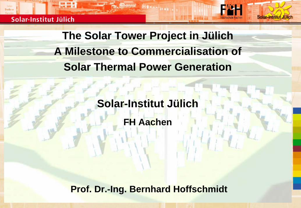
Power plant Power plant cyclecycle
~
Heliostat field
Receiver
turbine withgenerator
boiler
thermalstorage
compressor compressor
steam(480°C; 26 bar)
ambient air
Concentrator system hot gas cycle Water-Steam-Cycle
condenser
Hot air (680°C; 1 bar)
recirculation air (120°C; 1 bar)
concentratedsolar radiation
Solar Power Block Conventional power cycle
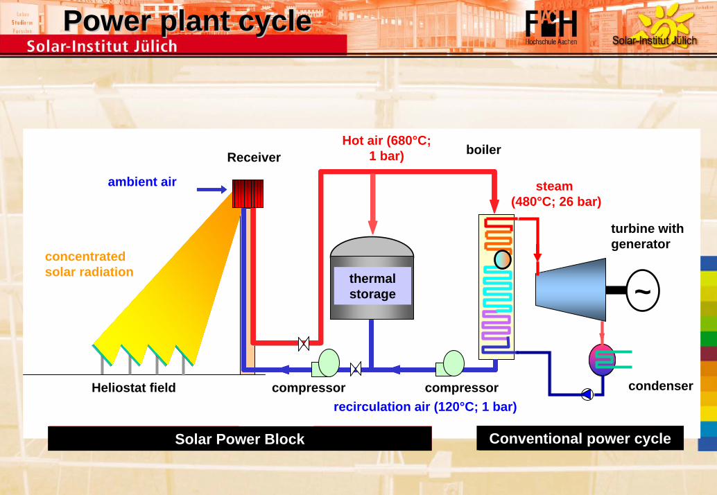
Hybridization
700°C hot air
ConventionalPower Block
Solar Power Block

Hybridization
ConventionalPower Block
700°C hot air~
Solar Power Block

Pilot plant Pilot plant -- MovieMovie

Feasibility Study

Feasibility Study
Tower

Feasibility Study
Tower

Feasibility Study
Tower

Feasibility Study
Tower

Feasibility Study
Function: Condenser
Condensation of wet steam
Water-Air Cooler
Usable for quick start up and shut done

Feasibility Study
Function: Turbine
Production of electrical power
Usable for quick start up and shut done
Max. electrical power 1500 kW

Feasibility Study
Function: Water Treatment
Water treatment of condensate for re-feeding into the boiler
Usable for quick start up and shut done

Feasibility Study
Function: Powerhouse
Junction of all data lines
Processing
Documentation

Feasibility Study
Function: Control Center
Control of plant
Visualization of operational and sensor data

Feasibility Study
Function: Storage
Compensation of fluctuating radiation
Keeping operation temperature during non operation
Capacity 1 hour of nominal operation

Feasibility Study
Function: Receiver and Steam Generator
Receiver (conversion of radiation energy in to hot air of 700°C)
Energy ducting from receiver to the steam generator and storage
Controlled vans, hot air distribution to steam generator and storage

Erection
0
50
100
150
200
250
300
350
400
450
500
550
600
-250 -200 -150 -100 -50 0 50 100 150 200 250
Function: Location
Adaptation to local topography
Selection of heliostats (mirrors) position
Fixing of tower dimension

Performance
Performance of Plant in Jülich
Maximal Electrical Power: 1,5 MW
Solar Radiation / DNI 800 kWh/m2a
Solar Multiple 1,2
Full Load hours 1000 h
Energy Production 1000 MWh/a
Ground Demand 18 ha (Algeria 6-8 ha)

Machbarkeitsstudie: Gesamtanlage

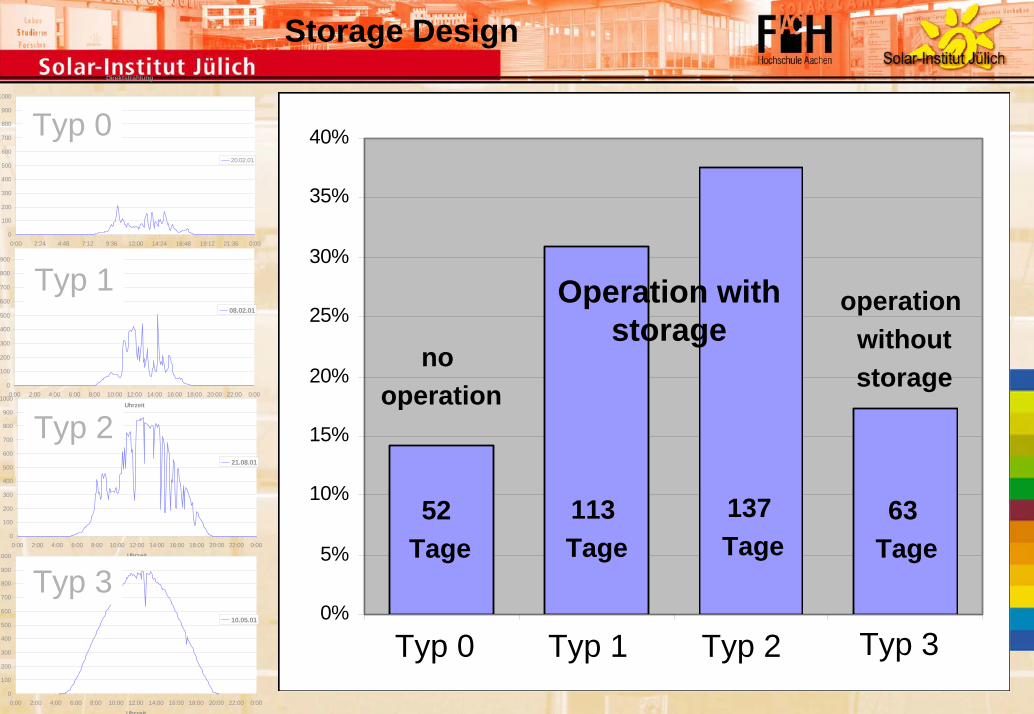
Storage Design
0
100
200
300
400
500
600
700
800
900
1000
0:00 2:24 4:48 7:12 9:36 12:00 14:24 16:48 19:12 21:36 0:00
Uhrzeit
DN
I [W
/m²]
20.02.01
0
100
200
300
400
500
600
700
800
900
1000
0:00 2:00 4:00 6:00 8:00 10:00 12:00 14:00 16:00 18:00 20:00 22:00 0:00
Uhrzeit
DN
I [W
/m²]
08.02.01
0
100
200
300
400
500
600
700
800
900
1000
0:00 2:00 4:00 6:00 8:00 10:00 12:00 14:00 16:00 18:00 20:00 22:00 0:00
Uhrzeit
DN
I [W
/m²]
21.08.01
0
100
200
300
400
500
600
700
800
900
1000
0:00 2:00 4:00 6:00 8:00 10:00 12:00 14:00 16:00 18:00 20:00 22:00 0:00
Uhrzeit
DN
I [W
/m²]
10.05.01
Typ 0Typ 0
Typ 2Typ 2
Typ 1Typ 1
Typ 3Typ 3
Direktstrahlung
0
100
200
300
400
500
600
700
800
900
1000
0:00 2:24 4:48 7:12 9:36 12:00 14:24 16:48 19:12 21:36 0:00
Uhrzeit
20.02.01
Typ 0
Direktstrahlung
0
100
200
300
400
500
600
700
800
900
1000
0:00 2:00 4:00 6:00 8:00 10:00 12:00 14:00 16:00 18:00 20:00 22:00 0:00
Uhrzeit
21.08.01
Typ 20
100
200
300
400
500
600
700
800
900
0:00 2:00 4:00 6:00 8:00 10:00 12:00 14:00 16:00 18:00 20:00 22:00 0:00
Uhrzeit
08.02.01
Typ 1
0
100
200
300
400
500
600
700
800
900
1000
0:00 2:00 4:00 6:00 8:00 10:00 12:00 14:00 16:00 18:00 20:00 22:00 0:00
Uhrzeit
10.05.01
Typ 30%
5%
10%
15%
20%
25%
30%
35%
40%
Typ 0 Typ 1 Typ 2 Typ 3Typ 0 Typ 2Typ 1 Typ 3
no operation
52 Tage
Operation withstorage
operation withoutstorage
113 Tage
137 Tage
63 Tage
Storage Design

Storage Design
Relative frequency of radiation gaps
Einstrahlung = 0W/m² (ohne Nächte und trübe Tage)
0%5%
10%15%20%25%30%35%
bis 5 bis10
bis15
bis30
bis45
bis60
bis90
bis120
bis180
bis240
bis300
bis360
über360
Dauer [min]
Häu
figke
it
Storage Capacity
Freq
uenc
y
Duration (min)

Future Future researchresearch aspectsaspects
Integration of aresearch plattform
Material tests under concentratedradiation (<2 MW/m2)Absorber designSensor system and controlstrategiesDevelopment of the systemcomponentsDirect Hydrogen production/synthetic fuels