The Solar Air Heater - The Renewable Youtry.com_08_10_02.pdf · The first step in the design and...
16
The Solar Air Heater Designed: May, 2005 Posted: September 11, 2008 (with Appendix not yet added.) Updated: October 2, 2008 [email protected]
Transcript of The Solar Air Heater - The Renewable Youtry.com_08_10_02.pdf · The first step in the design and...

The Solar Air Heater
Designed: May, 2005 Posted: September 11, 2008 (with Appendix not yet added.) Updated: October 2, 2008 [email protected]
The Renewable You, Copyright 2008. All Rights Reserved by Respective Owners and Creators. Love it. Use it. Don’t abuse it. 2
Abstract: This document will present the design and development of a solar powered air heater for personal use in a small room or apartment. The idea for such a design came up after months of freezing during my stay at my rent house in New York, and resentment for having to pay high electric bills and constantly use my space heater. All design decision will be made to address the below objective statement for this design. The actual design can be seen in Figures 2-4 and the report will work to prove the validity and viability of the design. Objective / Introduction:
One interesting characteristic about upstate NY is that the winters can sometimes be extremely cold, yet while the wind is howling and pushing up your heating bills, many below freezing days here in upstate are sunny and have an abundance of solar energy. Not only are many of the days sunny, but even the intensity of this winter sunlight is higher than other times throughout the year, because of a thin winter atmosphere. Over the past winter months, my frustration about rising gas and electric bills, constantly being cold, and often seeing the sun out even on the coldest of days led to me think of ways to that I could use this abundance of solar energy to heat my bitterly cold room. Taking what I have been reading from my reference text, Principles of Solar
Engineering, I began brainstorming ideas to make my room warmer, using the sun! My room does have a south facing wall, with one small vertical south window, but since this is a rent house, I am not at liberty to knock down the wall and turn my room into its own toasty fish tank. So while thinking of more viable ideas, I stumbled across heat exchangers in my reference and my idea for a solar air based heat exchanger came to mind. Something of the type could be installed on a rent house without a lot of mounting and could provide heat for my cold room throughout the winter months. Therefore, it is the goal of this report to present the design and analysis of a solar powered air heater simple enough to build from common building materials for affordable fabrication and installation on my rent house, for my room. The report will step through the calculations for the heating requirements of my room, and then present an air heat exchanger design set up to heat my room during sunny winter days. All analysis will be described, a list of needed materials will be included, as well as a cost summary, and energy savings, after all is complete. Statement of Need (Problem Statement):
The statement of need for this design is to keep my room, of a certain size, at a comfortable temperature during sunny winter days. Description of needs is summed up in the hand calculations, presented in Appendix A, Part 1 (not yet included in this report, but will be soon!). This Appendix presents the hand calculations and analysis for a solar space heater which will keep my room at a comfortable 70 degrees F on sunny days in the winter months.
The Renewable You, Copyright 2008. All Rights Reserved by Respective Owners and Creators. Love it. Use it. Don’t abuse it. 3
Synopsis of Solar Heater Design:
The following section presents the major findings of the analysis seen in Appendix A. It steps through the empirical values as well as the method for getting them, working to clear up any confusion from the hand calculations, as well as state all assumptions.
SECTION 1: Determination of size and losses in my room:
Seen in figure 1 of Appendix A, pg 2 is a diagram of my room, with the southern wall labeled. This diagram also presents my rooms dimensions, 8x11x11.5 ft. The outside and inside walls are labeled. Pgs 2-4 go through the convection and conduction losses in my room to determine the steady state losses. For the outside facing walls, both conduction and natural convection losses were considered, with the outside temperature set at 25 degrees F, and my room temperature set to 70 degrees F. Only conduction was considered when analyzing losses through the inner walls, ceiling and floor. The rest of my house was assumed to have a constant steady state temperature of 55 degrees F. The ACH of my room, which is pretty well sealed, as far as the door is concerned, was assumed to be 0.5. On page 5 of Appendix A, all of the losses are summed, along with the losses through the two 40”x40” windows in my room. Then, also on pg 5, an average value for the insolation was calculated using Table A2.6C from the Principles of Solar Engineering text for the month of February, which is a good representative winter month for my analysis. Taking the insolation values for the entire day, the value of 518 W/m^2 is an average to use in continuing my analysis. Then, the solar gains from my current southerly facing window are calculated, and subtracted from the total demand needed from the solar heater. This leaves the analysis of my room with a needed amount of heat energy for a steady temperature of 70 degrees F at 274 W.
Values from Appendix A, Section 1 analysis:
Qloss Northern Wall = 34.1 W Qloss Southern Wall = 53.1 W Qloss Eastern Wall = 32.6 W Qloss Western Wall = 51.2 W Qloss Ceiling and Floor = 60.26 W Qloss Windows = 2x 28.6 Q loss ACH rate = 43.17 W Q gain from South Window = 58 W SUMMATION OF ALL LOSSES = 273.6 W – this is the needed energy for my
room to stay at a temperature of 70 degrees F for steady state operation.
SECTION 2: INITIAL DESIGN ONE of the Solar Air Heater
The Renewable You, Copyright 2008. All Rights Reserved by Respective Owners and Creators. Love it. Use it. Don’t abuse it. 4
The first step in the design and analysis of the solar air heater is to look at the equations which describe its operation. The main equation for a solar flat plate collector is seen below, and comes from the course text, Principles of Solar Engineering is adapted below:
lossccccUseful QAIQ −= ατ
This equation shows that in order to calculate the useful steady state energy delivered from a solar collector, you need to know the incident insolation value, the frontal collection surface area, as well as the transmissivity of your glazing cover, the absorbtivity of your collector plate and the losses experienced by your collector during steady state operation. From the analysis of my room, it is known that the useful energy needed to be supplied to my room is 274 W. The insolation value used for analysis is the same as used above in the south facing window analysis, stated as 518 W/m^2. The transmissivity and absorbtivity of the heater materials are easy to find once the design of the heater has started, leaving the frontal collection area of the heater and the energy
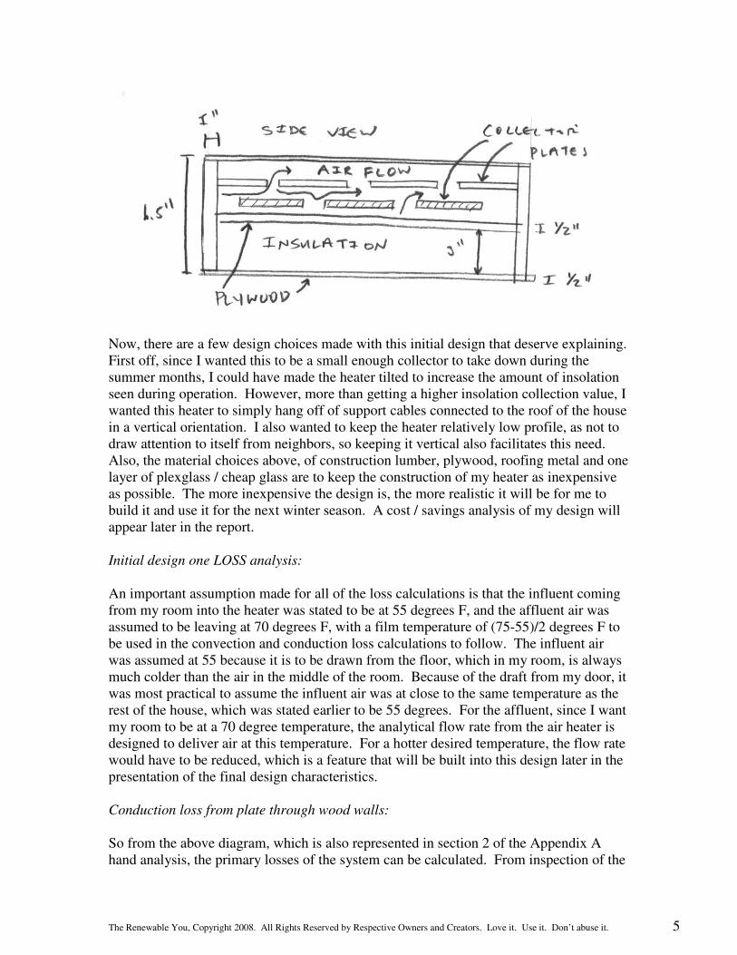
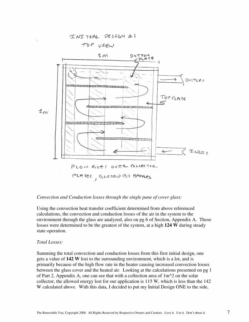
losses of the heater as our unknown variables in this analysis. Since this is the one steady state energy balance equation for a solar flat plate heater, there is one equation and two unknown values to solve for. Instead of trying to solve simultaneous loss equations with an area variable, I decided for my analysis to guess at an initial frontal area value, carry out the equations, and reiterate the solar heater design as needed. My initial frontal area value in my Appendix A calculations is 1m^2. From this point, the losses in the solar heater need to be calculated, much like the losses for my room were calculated, to determine if the initial design area of 1m^2 is too large or two small for the application of space heating my room. To calculate these losses, design decision need to be made about the solar heater. A hand sketch cross section diagram of my initial design is shown below for the solar heater. Basically, each side of the solar heater is a 6” x 1” x 1m piece of wood, with 3” of backboard insulation between two ½” plywood walls. This leaves approximately 2.5” for airflow of the air through the heating system. The collection plates are made of roofing metal, all black, with an assumed absorbtivity of .95 and are put in two layers supported by flow diverting plywood baffles to make sure the air passing through the heating system is stirred sufficiently into turbulent flow, for better heat exchange, and is channeled over as most of the solar collection surface as possible. The cover is a 1m^2 piece of glass, or plexiglass, with an assumed transmissivity of .95. The inner surface of the collector is painted all black to ensure high solar absorbtivity.
The Renewable You, Copyright 2008. All Rights Reserved by Respective Owners and Creators. Love it. Use it. Don’t abuse it. 5
Now, there are a few design choices made with this initial design that deserve explaining. First off, since I wanted this to be a small enough collector to take down during the summer months, I could have made the heater tilted to increase the amount of insolation seen during operation. However, more than getting a higher insolation collection value, I wanted this heater to simply hang off of support cables connected to the roof of the house in a vertical orientation. I also wanted to keep the heater relatively low profile, as not to draw attention to itself from neighbors, so keeping it vertical also facilitates this need. Also, the material choices above, of construction lumber, plywood, roofing metal and one layer of plexglass / cheap glass are to keep the construction of my heater as inexpensive as possible. The more inexpensive the design is, the more realistic it will be for me to build it and use it for the next winter season. A cost / savings analysis of my design will appear later in the report. Initial design one LOSS analysis:
An important assumption made for all of the loss calculations is that the influent coming from my room into the heater was stated to be at 55 degrees F, and the affluent air was assumed to be leaving at 70 degrees F, with a film temperature of (75-55)/2 degrees F to be used in the convection and conduction loss calculations to follow. The influent air was assumed at 55 because it is to be drawn from the floor, which in my room, is always much colder than the air in the middle of the room. Because of the draft from my door, it was most practical to assume the influent air was at close to the same temperature as the rest of the house, which was stated earlier to be 55 degrees. For the affluent, since I want my room to be at a 70 degree temperature, the analytical flow rate from the air heater is designed to deliver air at this temperature. For a hotter desired temperature, the flow rate would have to be reduced, which is a feature that will be built into this design later in the presentation of the final design characteristics.
Conduction loss from plate through wood walls:
So from the above diagram, which is also represented in section 2 of the Appendix A hand analysis, the primary losses of the system can be calculated. From inspection of the

The Renewable You, Copyright 2008. All Rights Reserved by Respective Owners and Creators. Love it. Use it. Don’t abuse it. 6
diagram, the primary losses are going to be heating loss through the single pane of glass on the lid of the absorber, the conduction losses of the hot collector plate through the wood siding of the absorber and the convection / conduction losses of the heated air through the wooden sides of the solar heater. Because of the heavy insulation on the back of the heater, losses through the bottom of the heater will be neglected. It will also be assumed that all of the radiation energy emitted from the collector plate is collected by the air in the heating system. Further assumptions will be stated as the analysis continues. For the conduction losses of the hot collector plate through the 1” wood siding of the collector, an initial value for the temperature of the collector plate needs to be calculated. To do this, Section 2 of Appendix A, pg 3 shows the energy balance equations of the collector plate assuming no convection losses are yet taking place. This basically uses the system balance that all of the energy absorbed from by the collector plate is emitted by the collector plate, so the energy balance equations work out to the below expression:
energyemittedTTAenergyabsorbed surrS _)(_ 44=−= σε
From this expression, Ts (the temperature of the collection surface) is the only unknown and can be solved for, resulting in a value of 345 K for this analysis. From this value, the conduction losses of the plate through the sides of the heater are calculated as 4.6 W for a 1m^2 collection area, as seen in Section 2, Appendix A, pg 6. Conduction and Convection loss of heated air through wood walls:
The next major loss for the first initial design is the convection and conduction losses of the heated air through the 1” side walls of the collector. But like the conduction loss calculation above, the convection coefficient h for the flow through the heater needs to be calculated before the losses of the heater can be evaluated.
Looking at the initial design diagram for the solar heater, one can see the flow diverting baffles designed to allow the flow to cover as much of the collector surface as possible. However, in the analytical sense, the flow moving from turn to turn is changed to an analysis similar to that seen in the diagram below, which is easier to look at, and still representative of the heating scenario. From this diagram, as seen on pg 4 of Section 2, Appendix A, the Reynolds number of the flow can be calculated, and from that, a convection heat transfer coefficient can be determined. From this heat transfer coefficient of 9.6 W/m^2C, losses due to convection and conduction with the side walls are determined on pg 6 of Section 2, Appendix A. This value was seen as 12.1 W steady state for the solar heater.
The Renewable You, Copyright 2008. All Rights Reserved by Respective Owners and Creators. Love it. Use it. Don’t abuse it. 7
Convection and Conduction losses through the single pane of cover glass:
Using the convection heat transfer coefficient determined from above referenced calculations, the convection and conduction losses of the air in the system to the environment through the glass are analyzed, also on pg 6 of Section, Appendix A. Those losses were determined to be the greatest of the system, at a high 124 W during steady state operation. Total Losses: Summing the total convection and conduction losses from this first initial design, one gets a value of 142 W lost to the surrounding environment, which is a lot, and is primarily because of the high flow rate in the heater causing increased convection losses between the glass cover and the heated air. Looking at the calculations presented on pg 1 of Part 2, Appendix A, one can see that with a collection area of 1m^2 on the solar collector, the allowed energy lost for our application is 115 W, which is less than the 142 W calculated above. With this data, I decided to put my Initial Design ONE to the side,

The Renewable You, Copyright 2008. All Rights Reserved by Respective Owners and Creators. Love it. Use it. Don’t abuse it. 8
and look at a new design, TWO, which worked to reduce the system airflow rate, and hopefully the system losses, without much effecting heat transfer to the moving air.
INITIAL DESIGN TWO: Same principles as initial design 1, different approach.
My second initial design got rid of the flowing baffles idea and concentrated more on keeping the air at a turbulent state, but also at a low flow rate. This design allows influent air to disperse along the total length of the heater and travel upwards past the metal collector plates as the air grows warmer, towards the output of the heater, and back into my room. See the hand sketch below:
Initial Design TWO LOSS analysis:
Much like the analysis of the first heater, this analysis uses many of the same initial parameters; i.e., fluid temperatures, starting plate temperature. As seen in the pages of Appendix A following the initial design ONE analysis, the TWO design starts off with
The Renewable You, Copyright 2008. All Rights Reserved by Respective Owners and Creators. Love it. Use it. Don’t abuse it. 9
calculation of a new convection heat transfer coefficient from the modified flow scheme. Appendix A, part 2, pg __ shows this calculation, and a value of 2.8 W/m^2C as the new convection coefficient. With this new value, the new loss values were calculated out to 4.6 W for the conduction losses between the collection plate and the wood, 11.8 W for the conduction and convection losses between the moving air and the wood, and 56 W for the conduction and convection losses between the glass plate and the moving air. This gave a total loss value of 73 W for the system, almost half of the loss value of design ONE. Initial Design TWO energy balance / collector temperature calculation:
With the energy loss of the collector design now at a reasonable number, the formula:
lossccccUseful QAIQ −= ατ
can now be reevaluated to determine if the area of 1m^2 for the solar collector is too large, or too small for this application. Looking at pg of Part 2, Appendix A, this calculation shows that with the loss value of 73 W, and our assumed average insulation value, which was stated above, the collection area of 1m^2 is in fact a little too large, producing 316 W of useful energy instead of the 273 W needed. So, in response to this, and in the spirit of iteration, the collection area was reduced to .9 m^2, and the losses recalculated on the following page. This boiled down to a useful energy value of 283 W, which is pretty close to our 273 W needed estimate. Therefore, the design collection area of .9 m^2 will be kept for the rest of the design. With the analysis of design TWO under wraps, it is clear to see that design TWO was the better design for this application, and will be the basis for the final design presented later in this report. The final handwritten calculations of Appendix A work to find the actual surface temperature of the black collector plate, to make sure the temperature did not get too hot as to burn the surrounding wood. For the wood to burn, the temperature would need to be on the order of a 200-300 degrees F. Looking at the bottom of pg __, Part 2, Appendix A, one can see the formula for the summation of the energy seen on the surface of the collector plate, and how it is equal to the useful energy needed for my room. From this, a simple convection and radiation analysis of the moving air over the plate can be completed, where the convection coefficient is the same as before, and the temperature of the surface of the collector plate is the only unknown. After analysis and iteration, it is seen that the collector plate reaches an average temperature of about 109 degrees F, which is not nearly hot enough to cause for concern, further validating design TWO. And to prevent from the collector plate ever getting too hot, the presented final design will have an adjustable flow rate ability, which on days of high isolation will allow for the flow to be turned up higher than normal, meaning the useful energy into my room will be higher than the needed 273 W. To make sure that my room is still comfortable, a bleeder valve on the output will be added to reject excess heat, or I will just keep my room door open, and spread this free energy to at least some of the surrounding house!

The Renewable You, Copyright 2008. All Rights Reserved by Respective Owners and Creators. Love it. Use it. Don’t abuse it. 10
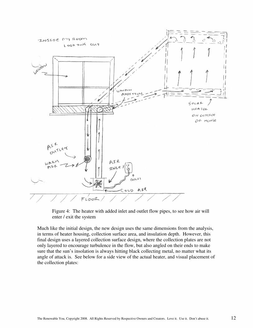
FINAL DESIGN: Utilizing concepts from the initial design TWO analysis: With a primary initial design chosen and analyzed theoretically, the final design and presentation of the solar room air heater can begin, along with a subsequent cost and energy saving analysis. First off, a few features that are to be included in the final design detail are such things as input and output paths, as well as flow control for the heater, dimensions concerning construction and other general improvements from the initial design. First off, the inlet draws cold air from the floor level of my room, near the existing vertical south window. The outlet will also be located near the floor, to allow for hot air coming from the heater to rise through the rest of the room, but not as to allow for heated air to pass back into the inlet draw. An insulated window addition will work to allow the inlet and outlet PVC tubes to carry air from inside my room, outside for heating with minimal window draft losses. Caulk and insulation will be used to make seals airtight. All outside PVC tubes will be painted black to allow for limited heat loss to and from my room, and will be routed through the insulation of the heater before being coming to or from the inlet / outlet. (See diagram below for reference).
The flow control will be done by use of a small installed fan, much like that of a computer fan located inside the inlet tube, or a small, inexpensive blower. This apparatus will facilitate the movement of air from the cold ground of my room to the heated compartment of the heater, and then back down through the PVC to my room. Faster flows will allow for a lower temperature of the incoming air, a lower collector plate temperature, and greater convection losses, while lower will allow for hotter heater air temps, hotter collector temps, but lower system losses. The user will have control over these by using the flow control. Another comfort measure on high intensity days will be opening of my room door to allow for excess heat to be donated to the rest of the house, adding to our energy savings. The final detailed design of the actual heater can be seen in detail below:
The Renewable You, Copyright 2008. All Rights Reserved by Respective Owners and Creators. Love it. Use it. Don’t abuse it. 11
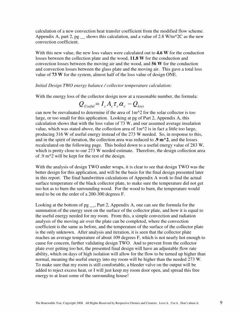
Figure 2: The exploded view of the heater, with respective components
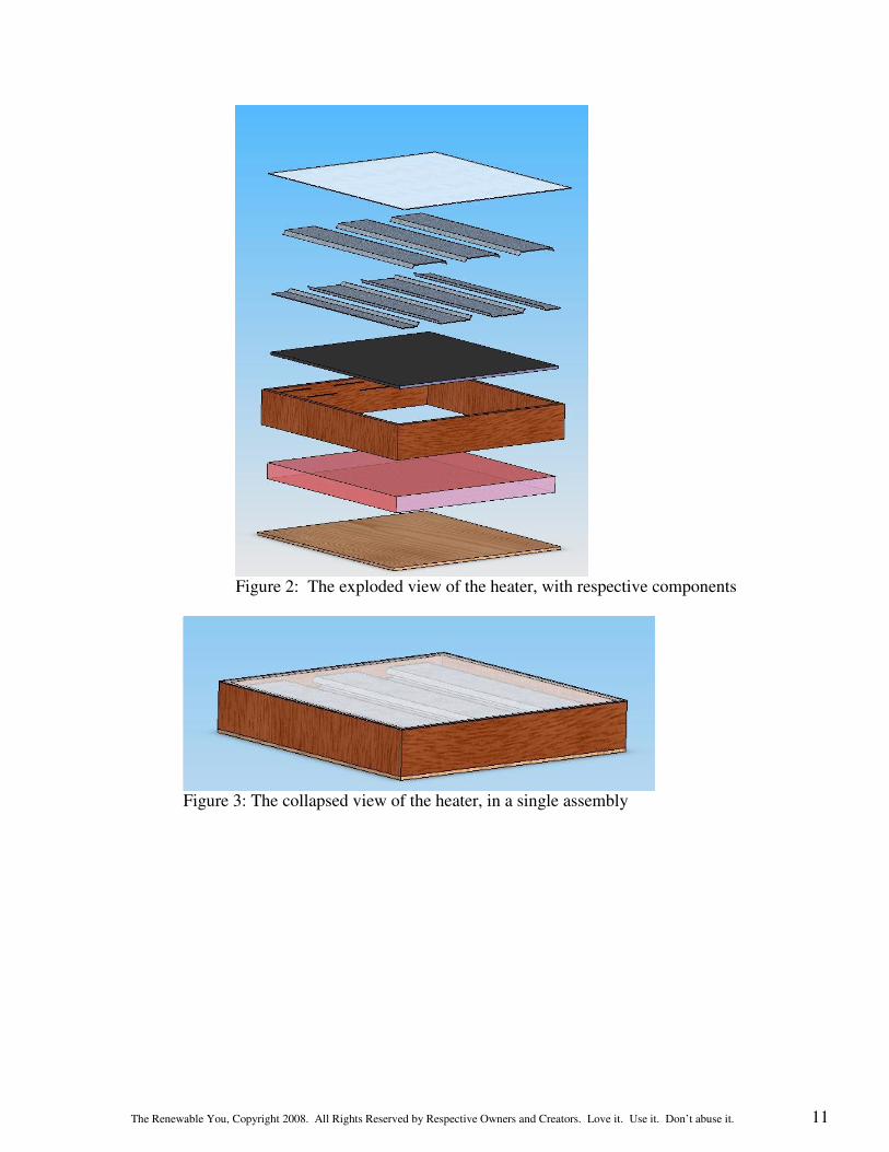
Figure 3: The collapsed view of the heater, in a single assembly
The Renewable You, Copyright 2008. All Rights Reserved by Respective Owners and Creators. Love it. Use it. Don’t abuse it. 12
Figure 4: The heater with added inlet and outlet flow pipes, to see how air will enter / exit the system
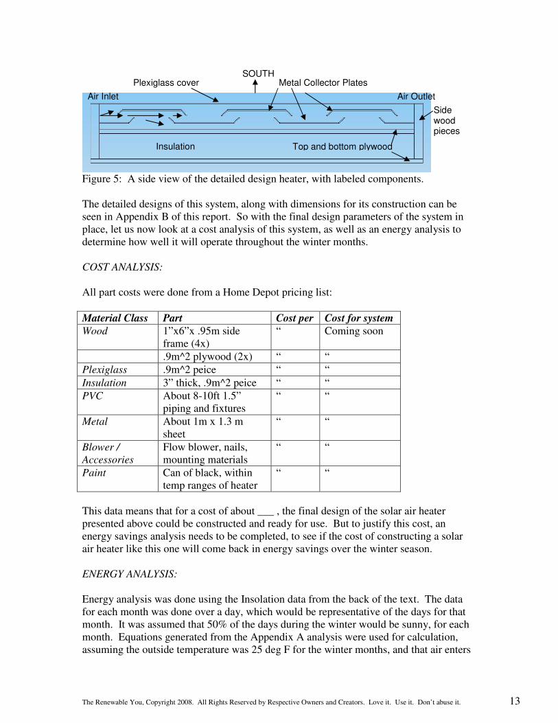
Much like the initial design, the new design uses the same dimensions from the analysis, in terms of heater housing, collection surface area, and insulation depth. However, this final design uses a layered collection surface design, where the collection plates are not only layered to encourage turbulence in the flow, but also angled on their ends to make sure that the sun’s insolation is always hitting black collecting metal, no matter what its angle of attack is. See below for a side view of the actual heater, and visual placement of the collection plates:
The Renewable You, Copyright 2008. All Rights Reserved by Respective Owners and Creators. Love it. Use it. Don’t abuse it. 13
Figure 5: A side view of the detailed design heater, with labeled components. The detailed designs of this system, along with dimensions for its construction can be seen in Appendix B of this report. So with the final design parameters of the system in place, let us now look at a cost analysis of this system, as well as an energy analysis to determine how well it will operate throughout the winter months. COST ANALYSIS:
All part costs were done from a Home Depot pricing list:
Material Class Part Cost per Cost for system
Wood 1”x6”x .95m side frame (4x)
“ Coming soon
.9m^2 plywood (2x) “ “
Plexiglass .9m^2 peice “ “
Insulation 3” thick, .9m^2 peice “ “
PVC About 8-10ft 1.5” piping and fixtures
“ “
Metal About 1m x 1.3 m sheet
“ “
Blower /
Accessories
Flow blower, nails, mounting materials
“ “
Paint Can of black, within temp ranges of heater
“ “
This data means that for a cost of about ___ , the final design of the solar air heater presented above could be constructed and ready for use. But to justify this cost, an energy savings analysis needs to be completed, to see if the cost of constructing a solar air heater like this one will come back in energy savings over the winter season. ENERGY ANALYSIS:
Energy analysis was done using the Insolation data from the back of the text. The data for each month was done over a day, which would be representative of the days for that month. It was assumed that 50% of the days during the winter would be sunny, for each month. Equations generated from the Appendix A analysis were used for calculation, assuming the outside temperature was 25 deg F for the winter months, and that air enters
Insulation Top and bottom plywood
Side wood pieces
Plexiglass cover Metal Collector Plates SOUTH
Air Inlet Air Outlet
The Renewable You, Copyright 2008. All Rights Reserved by Respective Owners and Creators. Love it. Use it. Don’t abuse it. 14
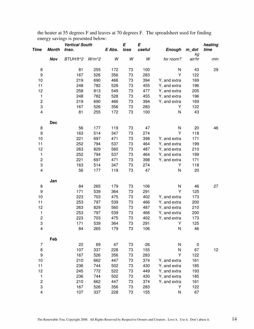
the heater at 55 degrees F and leaves at 70 degrees F. The spreadsheet used for finding energy savings is presented below:
Time Month Vertical South Inso. E Abs.
E loss
E useful Enough m_dot
heating time
Nov BTUH/ft^2 W/m^2 W W W for room? kg
air/hr min
8 81 255 172 73 100 N 43 29
9 167 526 356 73 283 Y 122
10 219 690 466 73 394 Y, and extra 169
11 248 782 528 73 455 Y, and extra 196
12 258 813 549 73 477 Y, and extra 205
1 248 782 528 73 455 Y, and extra 196
2 219 690 466 73 394 Y, and extra 169
3 167 526 356 73 283 Y 122
4 81 255 172 73 100 N 43
Dec
8 56 177 119 73 47 N 20 46
9 163 514 347 73 274 Y 118
10 221 697 471 73 398 Y, and extra 171
11 252 794 537 73 464 Y, and extra 199
12 263 829 560 73 487 Y, and extra 210
1 252 794 537 73 464 Y, and extra 199
2 221 697 471 73 398 Y, and extra 171
3 163 514 347 73 274 Y 118
4 56 177 119 73 47 N 20
Jan
8 84 265 179 73 106 N 46 27
9 171 539 364 73 291 Y 125
10 223 703 475 73 402 Y, and extra 173
11 253 797 539 73 466 Y, and extra 200
12 263 829 560 73 487 Y, and extra 210
1 253 797 539 73 466 Y, and extra 200
2 223 703 475 73 402 Y, and extra 173
3 171 539 364 73 291 Y 125
4 84 265 179 73 106 N 46
Feb
7 22 69 47 73 -26 N 0
8 107 337 228 73 155 N 67 12
9 167 526 356 73 283 Y 122
10 210 662 447 73 374 Y, and extra 161
11 236 744 502 73 430 Y, and extra 185
12 245 772 522 73 449 Y, and extra 193
1 236 744 502 73 430 Y, and extra 185
2 210 662 447 73 374 Y, and extra 161
3 167 526 356 73 283 Y 122
4 107 337 228 73 155 N 67
The Renewable You, Copyright 2008. All Rights Reserved by Respective Owners and Creators. Love it. Use it. Don’t abuse it. 15
5 22 69 47 73 -26 N 0
Mar
7 35 110 75 73 2 N 1 59
8 89 281 189 73 117 N 50
9 138 435 294 73 221 Y 95
10 176 555 375 73 302 Y, and extra 130
11 200 630 426 73 353 Y, and extra 152
12 208 656 443 73 370 Y, and extra 159
1 200 630 426 73 353 Y, and extra 152
2 176 555 375 73 302 Y, and extra 130
3 138 435 294 73 221 Y 95
4 89 281 189 73 117 N 50
5 35 110 75 73 2 N 1
E
total Savings ($)
421.7 kWh 127
and 1/2
days light 210.8 kWh 63
for season
at 30 cents a
kWh
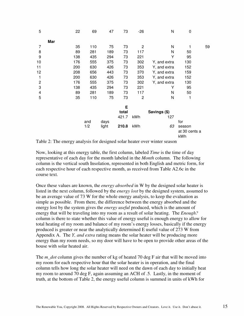
Table 2: The energy analysis for designed solar heater over winter season Now, looking at this energy table, the first column, labeled Time is the time of day
representative of each day for the month labeled in the Month column. The following column is the vertical south Insolation, represented in both English and metric form, for each respective hour of each respective month, as received from Table A2.6c in the course text. Once these values are known, the energy absorbed in W by the designed solar heater is listed in the next column, followed by the energy lost by the designed system, assumed to be an average value of 73 W for the whole energy analysis, to keep the evaluation as simple as possible. From there, the difference between the energy absorbed and the energy lost by the system gives the energy useful produced, which is the amount of energy that will be traveling into my room as a result of solar heating. The Enough?
column is there to state whether this value of energy useful is enough energy to allow for total heating of my room and balance of my room’s energy losses, basically if the energy produced is greater or near the analytically determined E useful value of 273 W from Appendix A. The Y, and extra rating means the solar heater will be producing more energy than my room needs, so my door will have to be open to provide other areas of the house with solar heated air. The m_dot column gives the number of kg of heated 70 deg F air that will be moved into my room for each respective hour that the solar heater is in operation, and the final column tells how long the solar heater will need on the dawn of each day to initially heat my room to around 70 deg F, again assuming an ACH of .5. Lastly, in the moment of truth, at the bottom of Table 2, the energy useful column is summed in units of kWh for
The Renewable You, Copyright 2008. All Rights Reserved by Respective Owners and Creators. Love it. Use it. Don’t abuse it. 16
the 5 months analyzed above and gives a value of 422 kWhrs. Now, with the assumption that 50% of the days of the winter give sufficient sunlight, this saved value is cut in half to 211 kWhrs saved over the season. And since this energy would be replaced by my space heater, which runs on electricity at about 18 cents per kWhr, the total season savings from implementation of this solar air heater would be roughly $40.00. Although this doesn’t sound large to begin with, since my heating bills this year were averaging 80 dollars a month, over a few winter seasons, the solar air heater is more than paid for, and the return on investment will kick in. Conclusion:
Overall, the design of this solar air heater has been a good experience. The initial idea was first drawn into two different concept designs, one of which was chosen through analytical synthesis to be a viable solar air heater. From there, final design documents were created using theoretical behavior analysis, and a heater which could actually be constructed was produced. Cost and energy analyses determined the practicality of the design, and the return on investment time span. Now the only thing left to do is build and use the solar heater! And with numbers as good as this final project has produced, building an operational solar heater will be the next step in this process, so come next winter, my room, and my comfort, will be powered by the sun and its free energy!