The Short-Circuit Amplifying Technique. - swissenschaft
37
The Short-Circuit Amplifying Technique. By Charles Douglas Wehner 28 July 2003 PRINCIPLES This story begins in the very early seventies. There was news in the technical press that there was a strange oscillation to be found “AT SOME ULTRASONIC FREQUENCY” in a small-signal silicon-planar transistor whose collector was shorted to its base. The author was aware that at normal temperatures, such as 20° C or 68°F, and one milliamp of current, the base threshold will be about 0.6v with +58mv per decade. The collector will saturate at about 0.2v. Page 1 of 37 The Short-Circuit Amplifying Technique 16.08.2005 http://www.wehner.org/electro/short/
Transcript of The Short-Circuit Amplifying Technique. - swissenschaft

The Short-Circuit Amplifying Technique. By Charles Douglas Wehner 28 July 2003
PRINCIPLES
This story begins in the very early seventies. There was news in the technical press that there was a strange oscillation to be found “AT SOME ULTRASONIC FREQUENCY” in a small-signal silicon-planar transistor whose collector was shorted to its base.
The author was aware that at normal temperatures, such as 20°C or 68°F, and one milliamp of current, the base threshold will be about 0.6v with +58mv per decade. The collector will saturate at about 0.2v.
Page 1 of 37The Short-Circuit Amplifying Technique
16.08.2005http://www.wehner.org/electro/short/

It was precisely for this reason that the author was in the habit of biasing his amplifier stages - even within multivibrators - by means of feedback from the collector and not directly from the supply. Rising gain at low temperatures can no longer stop the amplification.
So even with the base-bias resistor reduced to NIL, there was headroom enough at the collector for the device to amplify. Had the reporter been sloppy in his work? Has a tangle of wires generated uncontrolled parasitic inductance and capacitance?
SUPER-REGENERATIVE V.H.F. The explanation was correct. The author set to work, and within a day had created a radio receiver where there were only three turns of 15 SWG wire between the collector and base of the first transistor - and yet that transistor did not just amplify, but OVER-
Page 2 of 37The Short-Circuit Amplifying Technique
16.08.2005http://www.wehner.org/electro/short/

AMPLIFIED.
VT1 was nothing special - various devices such as 2N2926 were tried, with virtually identical performance. Most silicon devices, even in the seventies, had an Ft of 200MHz. or more.
Yet, with R1 set to 8.2 megohms, and a supply as low as 1.2v, this SUPER-REGENERATIVE design would squeg. Overamplification meant that the R.F. would rectify at the base of the transistor, until the drop in voltage on C1C2 caused the oscillation to stop.
Page 3 of 37The Short-Circuit Amplifying Technique
16.08.2005http://www.wehner.org/electro/short/

There was then a pause whilst the voltage recovered via R1.
Broadcast signals coming down the antenna would modulate the squegging delay, which in turn would modulate the D.C. on R1. This was in turn amplified by a single stage, VT2, which itself used only a microamp of current.
With a high-impedance piezo earphone, the design gave good volume at intelligible quality - despite the “HISS” that people associate with FM. This hiss is actually a fault, but a “FEATURE” in low-current super-regen designs like this.
Whilst setting it up, the author heard the audio of British BBC1 television at about 45 MHz., taxi-cabs from the other side of London at about 75 MHz., the entire 88-108 MHz. band, and the aeronautical weather station at about 160 MHz.. Pilots thirty miles away approaching Heathrow airport were also heard “COMING UP ON THE LOCALISER NOW”.
The design runs non-stop for about two years on a single tiny watch battery.
A gadget had been made that deliberately stretched incredulity to the limit. Minimum components, absurdly low current, frequencies close to the cut-off limit of the transistors, and yet the design was conspicuously bursting with activity.
SUPER-HETERODYNE A.M.
Page 4 of 37The Short-Circuit Amplifying Technique
16.08.2005http://www.wehner.org/electro/short/
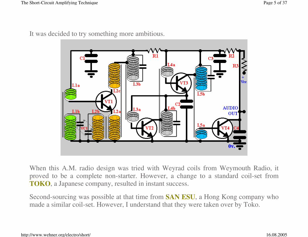
It was decided to try something more ambitious.
When this A.M. radio design was tried with Weyrad coils from Weymouth Radio, it proved to be a complete non-starter. However, a change to a standard coil-set from TOKO, a Japanese company, resulted in instant success.
Second-sourcing was possible at that time from SAN ESU, a Hong Kong company who made a similar coil-set. However, I understand that they were taken over by Toko.
Page 5 of 37The Short-Circuit Amplifying Technique
16.08.2005http://www.wehner.org/electro/short/

L1 was home-made. It was a coil of a few hundred turns wound onto a standard ferrite rod. The secondary, L1a, was about fifty times less. This coil was made in such a way that it would cover the medium waveband of 550 to 1500 kiloherz with a standard double-ganged variable capacitor VC1. The fitted padders and trimmers are not shown.
Whilst transistor VT1 amplifies the aerial signal in common-emitter mode, it also oscillates in common-base mode with the standard Toko oscillator coil L2.
Intermodulation produces the Intermediate Frequency, which I believe was 455 kiloherz, that is trapped by I.F. transformer L3 and fed via L3a to I.F. amplifying transistor VT2.
Another I.F. transformer L4 feeds via L4a onto the second I.F. amplifier VT3. NOTE THAT THE CURRENT TAKEN BY VT2 IS ALSO USED BY VT3.
The standard output coil L5 feeds the detector VT4. Here, instead of a collector-base short we have an emitter-base short. Yet there is adequate signal to give a reliable detection.
C4 promptly suppresses the R.F. component out of the audio.
The biasing behaviour requires some study:
Page 6 of 37The Short-Circuit Amplifying Technique
16.08.2005http://www.wehner.org/electro/short/

Mixer supply It will be seen that as the collector of VT1 is shorted to its base, the device from a DC viewpoint can be considered to be a 0.6v Zener diode. Similarly, the two I.F. amplifiers VT2 and VT3 act together as a 1.2v Zener diode.
The first thing to be seen, therefore, is that at no added expense a STABILISED POWER SUPPLY has been set up for the self-oscillating mixer.
Page 7 of 37The Short-Circuit Amplifying Technique
16.08.2005http://www.wehner.org/electro/short/

R1 was chosen to be 680 ohms, so that the self-oscillating mixer was running at just under a milliamp. For ultra low noise, this current can of course be increased. This is because at 0.6v and one milliamp the devices dissipates just 600 microwatts of power, leaving plenty of room for customising.
Audio bias That milliamp or so passes also through R3. We can calculate the voltage-drop across R3, and subtract it from the power-supply volts. This is the highest that is possible with the given values of R1 and R3. Let us call it Vmax.
If we now disconnect VT4 in our imagination, we will find extra current flowing down through R2 and R3. This defines the mid-point potential at the junction of R2 and R3. Let us call this Vmid.
Let us now reconnect VT4 in our imagination, and think of a steady I.F. signal obliging VT4 to take that extra current instead of it passing through R2 - which only carries the mixer milliamp. This is the situation when there is an EXTREMELY strong signal.
A.M. signals are symmetrical. Thus, the troughs in the I.F. signal that allow the collector volts of VT4 to rise to the upper limit are matched by peaks that allow VT4 to fall to its lowest point.
Accordingly, if (Vmax-0.2v.) is less than twice Vmid the detector VT4 cannot saturate
Page 8 of 37The Short-Circuit Amplifying Technique
16.08.2005http://www.wehner.org/electro/short/

on symmetrical signals.
That it saturates briefly on sudden non-broadcast bursts, such as due to an unsuppressed motor-vehicle, is actually a bonus. There is headroom at the detector for the official broadcast, but noise is clipped.
A.G.C. R2 and C3 form an integrator, which removes the R.F. signal from the I.F. amplifier supply line but also removes the high-frequency component of the audio. The 3dB point will generally be chosen to be at about 100 to 150 Herz.
This smoothed signal now passes through BOTH I.F. amplifiers. This gives powerful A.G.C. over the entire R.F. strip
The behaviour under conditions of variable signals is worthy of note:
Page 9 of 37The Short-Circuit Amplifying Technique
16.08.2005http://www.wehner.org/electro/short/

If the I.F. strip is taking a milliamp, both transistors act as resistors of 600 ohms. However, on a stronger signal that pulls down the A.G.C. and delivers only a tenth of that, the transistors behave as if they were about 6 kilohms.
Accordingly, VT3, C2 and VT2 behave like a “T-network” with a time-constant that is long on strong signals that deliver low I.F. current, and short on weak ones that allow the I.F. current to rise.
Page 10 of 37The Short-Circuit Amplifying Technique
16.08.2005http://www.wehner.org/electro/short/
The Kennelly-Heaviside layer is known to fluctuate. In the early days of Radio Luxemburg, when radio engineering was not so advanced, listeners in London were often frustrated by the rapid flutter of the sound under some conditions.
The variable A.G.C. time-constant of this design allows the bass to be received on strong local signals whilst sacrificing some of it to receive weak, distant, unstable signals at good quality.
These points were planned into the design, and confirmed by the prototype.
A 75 ohm loudspeaker was substituted for R3, and the design delivered a reasonable volume of sound - but with no control of volume other than by detuning.
CLOCKWORK It was at this point that the author decided, in 1976, to attempt to run this radio from CLOCKWORK.
This would normally be considered to be nonsense, but the extreme power economy of this design meant that it could be tried.
A typical 12-ligne men’s wristwatch - even when analogue, and therefore full of wheels - can run on a mercury battery for up to three years. The mainspring and drum of a mechanical watch are
Page 11 of 37The Short-Circuit Amplifying Technique
16.08.2005http://www.wehner.org/electro/short/

about the same size, but can manage only a single day.
It was realised, therefore, that the energy-storage capability would be about a thousand times less than with a chemical battery.
A broken clock was taken, and the balance-wheel removed. Its minute hand was connected by means of heat-shrinkable sleeving to the shaft of a TKK Mabuchi model motor. The terminals of that motor served as the power-supply to the above radio.
When the clock was wound and allowed to run, the motor delivered sufficient power for several seconds of sound from the radio.
The radio was tried with a high resistor at C3 and a piezo earpiece, and with a 75 ohm loudspeaker in that position. Both worked.
The motor appeared to deliver volts that were a reasonable approximation to a linear decline, so that the volume declined according to an approximate square law. This severely compromised the usefulness of the device.
Studies were made of the rate of run-down of the clockwork mechanism. It was clear that on light loads the mechanical system would run for about twice the time. The back-EMF from the motor was slowing the clockwork. However, the clockwork could NOT - of course - be brought to rest or there would be no back-EMF.
It was decided that a mechanical BRAKE must be fitted to the clockwork, so that when
Page 12 of 37The Short-Circuit Amplifying Technique
16.08.2005http://www.wehner.org/electro/short/
the volume-control is set to nil the clockwork stops and its stored energy preserved.
It was also observed that attempts to wind the spring whilst the system was running would cause the drive to be removed from the motor, so that the volts would stop and the radio would become silent.
It was immediately realised that the whole idea of a clockwork radio was therefore impracticable. A system with a rechargeable chemical battery, charged directly from the generator, would be better.
It was further decided that a small transformer and rectifier could provide the additional facility of recharging a battery from the domestic supply. There was no such easy way of rewinding a spring.
Again, a chemical battery could be easily recharged from a solar cell, but there was no such way of rewinding a spring from sunlight.
In a patent application by the author for the short-circuit amplifying technique, mention was made that the power economy was so low that the radio had been shown to work EVEN FROM CLOCKWORK, but no claim was made for the invention of the clockwork radio because its technical shortcomings made it a worthless idea.
In the English “Daily Mail” newspaper, a man who gave his name as ‘Dr.’ claimed that he had been granted a patent for the clockwork radio in 1985. He quoted the patent
Page 13 of 37The Short-Circuit Amplifying Technique
16.08.2005http://www.wehner.org/electro/short/

number.
In the later 1990s, a man who had formerly been begging on the streets of Berlin demonstrated on “Tomorrow’s World” on BBC television, a radio that ran for a few seconds from clockwork.
This ‘design’ consisted of a piece of formerly-discarded clockwork, a motor from a broken toy and the circuit panel from a broken radio.
There exists a “DISGUSTING GANG” in London, who specialise in creating disgusting people like Saddam Hussein.
They look for some small thing that you are ashamed of. Then, with threats of publishing and of punishing you, they force you to become filthier and filthier.
These are the “DARK FORCES” that the Queen spoke of.
Members of the gang had already put pressure on Nelson Mandela to send his civil service to London for “training”.
Had he agreed, his civil servants would have returned to South Africa full of guilt and the fear of exposure. They would have been British puppets.
On seeing the beggar on television, the gang rushed to him. “Do you believe in the Immortal Spirit? Do you believe in the Everlasting Soul? You could be an important man”!
The beggar discovered a sudden enthusiasm for religion. He instantly acquired the
Page 14 of 37The Short-Circuit Amplifying Technique
16.08.2005http://www.wehner.org/electro/short/

Presidential Gold and Silver medals of the Institute of Electrical and Mechanical Engineers. He instantly received the title of Master of Science from Brunel university, and became a visiting PROFESSOR at Buckingham university. He was wined, dined and filmed at Buckingham Palace.
Bristol university was given millions of pounds of tax-payers’ money to make a viable clockwork radio from the ‘prototype’.
A charity in South Africa was pressured into liberating large sums for the setting-up of a clockwork-radio factory.
“We use CRIPPLES because they are cheap” will have been the mentality. The disgusting gang told the world that they provide “jobs for the DISABLED”.
The beggar cried tears of joy when he saw that factory. On television, he explained that it had been such a tremendous battle before his GENIUS had finally been recognised. He was unaware that he was being USED.
At the big presentation of a clockwork radio, the beggar was introduced as “Professor Clever”. He smiled the way he had been trained to smile, and coaxed Nelson Mandela into turning the mighty wheel.
Bristol university had put in a TITANIC spring as a solution to the energy-storage problem. The ratchet-wheel was of TITANIC proportions, as was the pawl.
The wheel refused to budge.
Professor Clever urged Mandela to have another try. The Elder Statesman of Africa pushed with all his might, and suddenly..... CLUNK!
Page 15 of 37The Short-Circuit Amplifying Technique
16.08.2005http://www.wehner.org/electro/short/

This was the moment that nearly changed world history. Had the clockwork radio done for Mandela what years of imprisonment had failed to achieve?
Mandela sat there in a state of SHOCK. His heart was obviously fluttering - but would it stop?
No. He recovered, and the world was saved.
“That’s VERY NICE ”, he mumbled without conviction.
The clockwork radio factory promptly went bankrupt.
Professor Clever was ALLEGEDLY paid off with £180,000 (Sterling). However, on joining the gang you swear an oath not to do anything without permission. He lives in hope of being allowed one day to spend it.
He went on to invent the CLOCKWORK COMPUTER, in which you wind the TITANIC spring for 24 hours and get an uninterrupted 20 seconds of computing bliss before the system crashes, and you lose all your data.
In the (London) Daily Mail he lamented “I telephone my colleagues in South Africa, but they REFUSE TO RETURN MY CALLS....”
Voltage tuning One variant that was planned - but not fully explored - was the use of a digital system to control the tuning. This would use voltage tuning.
Page 16 of 37The Short-Circuit Amplifying Technique
16.08.2005http://www.wehner.org/electro/short/

It is known that the thickness of the depletion region in a silicon diode varies directly as the reverse voltage - but only when that reverse voltage is measured from the 0.6v threshold point.
Devices have been made with special mesas, and neutron doping, in order to defeat the natural law of the diode. Such specialised diodes have a linear law for use in such circuits as the Wien bridge.
However, Nature seems to be telling us something about good design. At low voltages, the frequency of an LC tank circuit (where C is a varicap) varies reasonably linearly with voltage.
Consider the following circuit alteration:
Page 17 of 37The Short-Circuit Amplifying Technique
16.08.2005http://www.wehner.org/electro/short/

Here, with nil tuning volts, DV1 is forward biased to its threshold. It is just conducting, and the L1DV1 frequency is nil.
DV2, on the other hand, has NIL bias. Its capacitance is what one would expect to measure on a capacitance meter with a disconnected device. This, together with L2b, should be set to the I.F. frequency (455 kHz.).
So now we raise the tuning volts to 0.6. L1 was designed so that L1DV1 now delivers
Page 18 of 37The Short-Circuit Amplifying Technique
16.08.2005http://www.wehner.org/electro/short/

455 kHz, and as the width of the depletion layer of DV2 is doubled, its capacitance has fallen by a square law to a quarter and the L2bDV2 frequency is 910 kHz.
So it goes on, with a fixed 455 kHz difference. The system allows voltages from 0.659 to 1.978 to cover the medium-wave band of 500 to 1500 kHz.
Higher frequencies are possible at higher volts - but the inverse square law of the diode acquires some inverse cube law. In addition, the parasitic capacitances become more significant as the varicap capacitance decreases.
The concept is just one of a series of ideas conceived for the simplification of production - with no padders and trimmers to adjust.
Whether the volts come from a potentiometer or a digital system depend upon the manufacturer’s design specification. A digital circuit can, for example, be frequency-stabilised by a “huff-and-puff” system.
SUPER-HETERODYNE F.M. The viability of amplification in the region of 100 MHz. had been proven with the very first design. However, it was time to try to compete with the best of the F.M. superhets.
Page 19 of 37The Short-Circuit Amplifying Technique
16.08.2005http://www.wehner.org/electro/short/

L1 and L2 were home-made coils of a few turns of stout wire. The first stage, VT1, is again a self-oscillating mixer. Separate oscillator and mixer circuits could have been built, but this was not tried.
L3 and L4 are standard TOKO 10.6 MHz I.F. transformer stages. The author had many of these, and decided to use them in positions L5 and L6 as well.
A Travis or Foster-Seeley discriminator could have been constructed, but WHY USE PASSIVE DEVICES?
Page 20 of 37The Short-Circuit Amplifying Technique
16.08.2005http://www.wehner.org/electro/short/

Instead, L5 and L6 are detuned to the lower and upper sidebands of the I.F. signal. The detectors VT4 and VT5 then give detection with gain.
VT4 and VT5 form a LONG-TAILED PAIR with R3, which helps linearise the output - but there is MORE.
The A.G.C. is ULTRASONIC.
What this means is that the time-constant R2C3 is made less than a sixty-thousandth of a second. The 3dB roll-off point will be at about 10 kiloHerz.
So any mismatch between devices VT4 and VT5, as well as any A.M. breakthrough, will be cancelled by the A.G.C. at audible frequencies.
C2 is also made small, so that it creates a similarly short time-constant with transistors VT2 and VT3 at their nominal current of a milliamp (600 Ohms). The overall effect is an astonishing level of A.M. rejection.
It did not escape the author’s attention that having switchable capacitors in positions C2 and C3 would allow the same I.F. strip to be used for A.M. and F.M. in a dual-standard design.
At the detectors VT4 and VT5, resistors R4 and R5 are chosen to make saturation impossible. This was described for the A.M. design above.
Page 21 of 37The Short-Circuit Amplifying Technique
16.08.2005http://www.wehner.org/electro/short/

Capacitor C4 forms with R4 - and C5 with R5 - a time-constant to match the de-emphasis standards of the broadcasting authorities. This will be 50 microseconds in Britain, and 75 in the U.S. and Germany, for example.
The symmetry of the detectors was maintained not only to maximise the A.M. rejection, but also for studies of push-pull output applications.
R6 and R7 are megOhms, compared with the kilOhms of R4 and R5. They form with C6 and C7 a time-constant of about a tenth of a second. Thus, if the lower sideband is too strong the volts on C6 will feed to the anode of varicap diode DV1 in such a way as to raise the frequency of the oscillator.
Similarly, if the upper sideband is too strong, the capacitance of DV1 will increase.
C8 is just a picoFarad or so - it consists of a couple of pieces of lacquered wire, about a quarter of an inch long, twisted together. A positive A.F.C. lock was detected.
In addition, a study was made of the extraction of stereo sound from the system:
Page 22 of 37The Short-Circuit Amplifying Technique
16.08.2005http://www.wehner.org/electro/short/

Here we see how the unused side of the discriminator delivers the pilot-tone to a coil, L7, tuned to 19 kiloHerz. Transistor VT7 is turned on whenever that tone appears, and the red LED lights up.
But the half-wave rectification of the 19 kiloHerz tone generates a high level of second-harmonic signal at 38 kiloHerz, which is trapped by L8.
The secondary of L8 is strapped between the bases of TWO transistors, VT5 and VT6 where in the mono design there was VT5 alone.
Page 23 of 37The Short-Circuit Amplifying Technique
16.08.2005http://www.wehner.org/electro/short/

In this way, the bases of these two transistors have a composite of I.F. and 38 kiloherz upon them. One will be biased off to leave the other to detect the signal, and then the action rocks back to the other.
The author was working on this design when he was disturbed by somebody knocking at the door.
“COME IN”, he called. Nobody responded.
Again there was a knock. Again, the author called out “Come in”.
Then a great drama unfolded - and it was indeed a drama. It was the sound-track of British television.
This kind of experience shows that the electromagnetic environment in the V.H.F. region is extremely quiet. Yet, years earlier, when working for the British Radio Corporation, the author had always experienced V.H.F. designs to hiss.
What was becoming clear was that the cause of the hiss was not in the environment - but POOR NEUTRALISATION OF THE I.F. STAGES.
The short-circuit design, with dozens of biasing resistors and their bypass capacitors removed, has such simple lay-out that neutralisation is rarely a problem.
However, a shortage of ready-made coils and of time to create hand-made ones meant
Page 24 of 37The Short-Circuit Amplifying Technique
16.08.2005http://www.wehner.org/electro/short/

that the stereo converter was never perfected.
When the stereo was switched on at the transmitter, the red led lit as expected. The hiss level increased from inaudible to noticeable. The stereo discrimination, however, was uncertain.
Had a viable stereo-pair been achieved it could have been improved. This could be arranged as follows:
If there is ten percent of left in the right, and ten percent of right in the left, you add ten percent of the ANTIPHASE signal from whence you took the pilot-tone. This leaves the left and right pure, and at 90% of their original voltage.
The author had come to Britain in 1973 to stop the country from starting trade with the Common Market.
The reason was that the parity of Sterling was three times too low. By 1976 it was already SIXFOLD undervalued. A major economic calamity was about to unfold.
The author had been unaware that there was a disgusting gang who were forcing through this trading agreement simply to ROB EUROPE.
The author was unaware that the ‘eminences’ who delivered ‘learned economic advice’ were just beggars and thieves like ‘Professor Clever’.
So the author broke off much of his electronics research to attend to trying to save British industry - and to avert a world recession.
Page 25 of 37The Short-Circuit Amplifying Technique
16.08.2005http://www.wehner.org/electro/short/

The ‘Professor Clever’s failed to understand the warnings. The Queen signed for trade in 1977. All industry collapsed. The author fled to Europe, because he anticipated some kind of ‘Winter of Discontent’. That winter came in 1979.
U.H.F. MODULATOR AND PATTERN GENERATOR Just before leaving the country, the author decided on one last experiment - to take the technique up close to a gigaHerz.
A television test-pattern generator was made, in which the R.F. modulator had a half turn of printed coil. Lecher lines were not attempted, because these have a sharp resonance. After all, the purpose was to cover the 430 to 860 megaHerz band.
Page 26 of 37The Short-Circuit Amplifying Technique
16.08.2005http://www.wehner.org/electro/short/

The British line-standard is 312.5 lines at 50 fields per second. The American is 262.5 at 60. Thus, the British line-rate is 15625 per second where the American is 15750.
L1 was a standard 455 kiloHerz I.F. transformer with a capacitor added to pull it down to 156250 Herz. It forms a short-circuit oscillator with VT1.
The decade-counter IC1 delivers ten patterns of binary at its four outputs. It is a 7490, which has a divide-by-two stage and a divide-by-five stage. The linkage that converts this to a divide-by-ten is not shown.
Page 27 of 37The Short-Circuit Amplifying Technique
16.08.2005http://www.wehner.org/electro/short/

Normally, the four outputs - units, twos, fours and eights - would be connected to resistors of say, eight, four, two and one kilOhms. Then, a regular staircase is generated.
However, such accuracy was not needed. "Preferred values" from the European E12 series were chosen instead, and the eights bit was deliberately given an excessively low resistor.
The result was as follows:
British television uses negative vision modulation, where black is presented as a high voltage. Sync pulses are higher still - BLACKER THAN BLACK.
This waveform delivers eight bands across the screen, with the brightest on the left. The
Page 28 of 37The Short-Circuit Amplifying Technique
16.08.2005http://www.wehner.org/electro/short/

vertical timebase was allowed to run free.
In a basement full of colour televisions, all tuned to a standard broadcast, the appliance was switched on. About fifteen television receivers simultaneously switched over to show the grey-scale.
Experiments were done throughout the 430 to 860 megaHerz band. The performance was consistent throughout.
A Phillips colour test-pattern generator was plugged into the socket. All televisions then showed the colour pattern. Here, the vertical timebase was properly synchronised.
Since that time, many people have manufactured modulators to cater for the computer craze. The earliest home computers were designed to display their output on the domestic television.
However, throughout that period nobody marketed a product with a modulator as simple as this - printed coil L2, transistor VT2, tuning capcitor VC1 (a single blade on the circuit-board, insulated with mica) and bypass capacitor C2.
Indeed, although the designs shown are considerably cheaper and better than the established circuits, at no time in the thirty years since they were conceived was anything resembling them put on the market.
A silicon transistor might give a minimum current gain of 50 - or 17dB. Depending on
Page 29 of 37The Short-Circuit Amplifying Technique
16.08.2005http://www.wehner.org/electro/short/
the design, in common-emitter mode it might also deliver a similar voltage gain. Thus, 34dB should be available.
Resistive coupling between stages causes much of that gain to be wasted - whilst resistor shot-noise is added.
Transformers are one of the most efficient devices conceived by Man. They contribute negligible noise, and can convert the voltage gain into current gain. Thus, with optimum matching of the transformer to the transistor one transistor delivers the performance that would require two in a resistively-coupled circuit.
All of this spells low noise.
Even though the advances in integrated-circuit production have led to radios being cheap and easy to manufacture, there is room at the top end of the market - the Hi-Fi and low-noise sector - for designs using coils.
The extensive use of robotics in production also makes the concept commercially viable.
Page 30 of 37The Short-Circuit Amplifying Technique
16.08.2005http://www.wehner.org/electro/short/
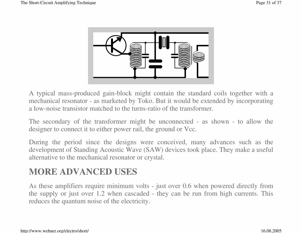
A typical mass-produced gain-block might contain the standard coils together with a mechanical resonator - as marketed by Toko. But it would be extended by incorporating a low-noise transistor matched to the turns-ratio of the transformer.
The secondary of the transformer might be unconnected - as shown - to allow the designer to connect it to either power rail, the ground or Vcc.
During the period since the designs were conceived, many advances such as the development of Standing Acoustic Wave (SAW) devices took place. They make a useful alternative to the mechanical resonator or crystal.
MORE ADVANCED USES As these amplifiers require minimum volts - just over 0.6 when powered directly from the supply or just over 1.2 when cascaded - they can be run from high currents. This reduces the quantum noise of the electricity.
Page 31 of 37The Short-Circuit Amplifying Technique
16.08.2005http://www.wehner.org/electro/short/

The signal is presented via a transformer to a transistor, transformed into the next transistor, transformed into the next and then transformed into the detector. There is nothing else in the signal path.
The bypass capacitors on the power lines suppress the resistor noise.
Accordingly, one begins to think of uses for the concept in special amplifiers for radioastronomy. They might offer a commercially viable alternative to maser and photomultiplier systems.
Yet, at cryogenic temperatures (solid carbon-dioxide or even liquid helium), there is the possibility of gas-bubble formation. When designing amplifiers for very low temperatures, this should be borne in mind.
In addition, the transistor gain rises as the temperature falls - a bonus, when designed for. However, the threshold of the transistor rises from 0.6 towards about 2 volts. The author does not any longer have access to his reference material to quote exact figures.
Page 32 of 37The Short-Circuit Amplifying Technique
16.08.2005http://www.wehner.org/electro/short/

In a microprocessor-controlled application such as Rahman Spectroscopy, a gate such as the field-effect transistor FET1 may be incorporated.
A pilot burst is sent through the amplifier to stabilise its gain. Then the gate is closed whilst the feeble signal is detected.
In this way, the gain can be made independent of the signal.
Page 33 of 37The Short-Circuit Amplifying Technique
16.08.2005http://www.wehner.org/electro/short/

The author returned to Britain in 1983, to find all industry gone.
He bought a house in Wales, and the British government immediately set about encouraging crime. Perhaps a ton of industrial components - transistors, resistors, capacitors, circuit boards, connectors and other parts - were destroyed. The author’s antiques were also variously stolen or destroyed.
It made no difference to the disgusting government that the author had delivered the key information that saved the economy in 1985.
Industrial prototypes were wrecked. Optical devices and large numbers of patent scripts were demolished.
The author, having lost his home, sought refuge with a good landlord in Hampstead, London.
Then the disgusting gang bought out that landlord cheaply, and illegally evicted everybody.
THEN CAME THE 11th OF SEPTEMBER.
The disgusting government were now thrilled. They had the excuse they needed for WAR. Orders seem to have gone out to “KILL SOMEBODY”.
People who have already killed in England make better killers when they are sent to Iraq.
The government had created vast numbers of fake doctors. Harold Frederick Shipman was a drug dealer who was dressed-up as a doctor. He was taught to kill in a hospital, where the other fake doctors killed the patients with heroin.
Page 34 of 37The Short-Circuit Amplifying Technique
16.08.2005http://www.wehner.org/electro/short/

The author’s own father, Dr. Carl Heinrich Wehner, was killed by disgusting doctors using heroin in a hospital in Dulwich, London. Therefore, when the newspapers reported that there were 50,000 INVOLUNTARY EUTHANASIAS every year in Britain, the author realised that this is true.
The principle of the disgusting gang is to commit crime on such a huge scale that nobody will believe it.
Shipman had a huge salary going into his account, but was not allowed to spend any. Living in poverty, Shipman developed a PIGGY BANK obsession. He killed 862 people - mainly old ladies - just for the contents of their piggy banks.
The rapists Ledward, Alison and Walton were similarly installed as fake doctors. They were described as “Gynaecologist”, “Psychiatrist” and “General Practitioner”.
It seems that when the order went out to KILL, some members of the gang who had only raped refused to be corrupted any further. There was a spate of fake doctors being prosecuted during the closing months of 2002, the above three amongst them.
A REAL doctor was sent to visit the author, and she immediately diagnosed Addison’s disease, a very rare disease that she had nevertheless seen before.
There was, of course, a scam involved. Now the disgusting government had a document that could be interpreted two ways:
1. The patient was ill, so there is no culprit.
2. The accused can be shown to have been in possession of the document, and has therefore deliberately killed a vulnerable person.
Page 35 of 37The Short-Circuit Amplifying Technique
16.08.2005http://www.wehner.org/electro/short/

So the way was now open to arrange the murder and compromise the murderer.
On 17th december 2002, the author was evicted onto the street. Government documents were prepared that declared that he had “Made himself deliberately homeless”.
The author had the fatal Addison’s disease, plus sepsis and a high temperature. The weather was well below zero, and it was snowing.
After a very close encounter with death, the author escaped into Europe.
Against this backdrop, there is absolutely no hope for the author to build any industry.
However, there are those on this planet who are well placed to put the knowledge of the short-circuit technique to good use.
A man who has been robbed of everything by corrupt government is in no position to hand out free gifts. However, such knowledge as is presented here is only of use when it is USED.
The knowledge is given in trust to the world, that it be preserved and used. As great savings can be made in industry, by rights a percentage of profits should be held in trust for the author.
THE DESIGNS, WITH FEW EXCEPTIONS, ARE FULLY TESTED AND PROVEN.
Page 36 of 37The Short-Circuit Amplifying Technique
16.08.2005http://www.wehner.org/electro/short/

(C) 1973-2003 Charles Douglas Wehner. Use freely but do not plagiarise.
It is not only bipolar transistors that can be short-circuit biased. There are two kinds of unipolar field-effect transistor - ENHANCEMENT mode and DEPLETION mode.
Enhancement mode transistors - as in COSMOS logic, for example - need to be biased on. A DC short-circuit from gate to drain will do this.
The emphasis was put on the bipolar devices because their threshold voltage is dependent upon the band-gap potential of silicon. This is defined by natural laws. The threshold of a FET is more dependent upon device geometry, and not so easily specified in a general article such as this.
HOME
Page 37 of 37The Short-Circuit Amplifying Technique
16.08.2005http://www.wehner.org/electro/short/