The Role of Bulk Energy Storage in Facilitating Renewable Energy Expansion
24
The Role of Bulk Energy Storage in Facilitating Renewable Energy Expansion Facilitating energy storage to allow high penetration of intermittent Renewable Energies
Transcript of The Role of Bulk Energy Storage in Facilitating Renewable Energy Expansion

The Role of Bulk Energy Storage in Facilitating Renewable Energy Expansion
Facilitating energy storage to allow high penetration of intermittent Renewable Energies

The work for this report has been coordinated by Energy Economics Group (EEG), Vienna University of Technology, Austria
Authors Organisation E-mailKarl Zach EEG [email protected] Auer EEG [email protected]ünther Körbler EEG [email protected] Lettner EEG [email protected]
All photos © VERBUNDGraphic Design: Guillaume Korompay, www.korompay.at
Final Version, September 2012
The sole responsibility for the content of this report lies with the authors. It does not necessarily reflect the opinion of the European Union. Neither the EACI nor the European Commission are responsible for any use that may be made of the information contained therein.

3
Table of Contents
1 Introduction ...................................................................................................... 42 Principles of Pumped Hydro Energy Storage .................................................. 6 2.1 Basic Functional Principle ........................................................................ 6 2.2 Closed-Loop PHES .................................................................................. 7 2.3 Semi-Open PHES .................................................................................... 73 Economics of Bulk Energy Storage Technologies ........................................... 8 3.1 Capital Costs ........................................................................................... 8 3.2 Price Arbitrage ......................................................................................... 94 Applications of Bulk Energy Storage Technologies ....................................... 10 4.1 Primary, Secondary and Tertiary Control ............................................... 10 4.2 Blackstart Capability .............................................................................. 12 4.3 Transmission and Distribution Investment Deferral ............................... 12 4.4 Management of RES-E .......................................................................... 125 Contribution of Pumped Hydro Energy Storage in Future
European Electricity Systems ........................................................................ 14 5.1 Pumped Hydro Energy Storage in European Context ........................... 14 5.2 Comparison of Selected Results ........................................................... 16 5.2.1 BAU Scenario 2030 .................................................................... 16 5.2.2 GREEN Scenario 2050 ............................................................... 176 Role of Cross-Border Transmission Grid Expansion
and Extreme Weather Events........................................................................ 187 Conclusions / Outlook ..................................................................................... 208 References .................................................................................................... 22 List of Abbreviations ...................................................................................... 23

4
The information and discussions presented in this report are part of the European project stoRE (www.store-project.eu). stoRE aims to facilitate the realization of the ambitious objectives for high penetration of variable / intermittent renewable energies in the European grid by 2020 and beyond, by unblocking the potential for energy storage technology implementation. In the stoRE project the focus of analysis and discussions is set predominantly on bulk energy storage technologies (EST)1, namely pumped hydro energy storage (PHES) and compressed air energy storage (CAES)2.
Bulk EST are expected to be one of the key enabling technologies for the integration of large amounts of variable / intermittent electricity generation from renewable energy sources (RES-E). In particular, the ability to quickly discharge large amounts of stored electricity or to reduce loads during certain points in time throughout a day (i.e. output smoothing) can mitigate many challenges that arise from high shares of variable / intermittent RES-E generation in the electricity system. Furthermore, bulk EST could also play an important role in optimising the physical and financial functioning of electricity markets and the corresponding commercial energy trading activities.
The purpose of this publication is to provide a collection, evaluation and update of information about the status and future potential of bulk EST.
1 Introduction

5
1 For a complete picture of energy storage options see Zach et al, 2012b, which also provides a brief overview of other (non-bulk) EST being outside the scope of the stoRE project.
2 For better readability, this document focusses on PHES since there are currently only two CAES systems in operation worldwide. However, CAES systems might also play an important role in the future, but further technological developments are needed in order to reach higher overall efficiencies and to eliminate the need for using additional fossil fuels. See Zach et al, 2012b for more details.
Section 2 gives an overview of the basic functional principle and different types of PHES systems.
In section 3 the economics of PHES systems and the main revenue stream for bulk EST, price arbitrage, are described. Further applications (and possible revenue streams) of bulk EST are specified in section 4.
Section 5 of this document provides estimates of the possible direct benefits and the possible future contribution of bulk EST implementation to balance incumbent regional electricity systems. For this, bulk EST potentials are identified and matched with the spatial dispersion of future RES-E deployment and the existing thermal power plant-portfolio on regional level in Europe. The possible coverage of the residual load curve for the years 2030 and 2050 and for two different scenarios (low / high RES-E expansion) with existing thermal power plants and bulk EST was analysed.
Section 6 analyses the contribution of possible future corridors on transmission interconnectors on ENTSO-E’s (European Network of Transmission System Operators for Electricity) transmission grid for load smoothing and bringing together variable / intermittent wind generation and bulk EST in different European electricity market regions. Furthermore, the effects of extreme weather events (positive / negative correlation of wind) are qualitatively discussed.
Overall conclusions are drawn in section 7.

6
2.1 Basic Functional Principle
Pumped Hydro Energy Storage (PHES) systems have been the main economic option for storing large amounts of electrical energy already for a long time. Currently there are more than 127 GW of PHES systems installed worldwide, representing over 99% of global electricity storage capacity (EPRI, 2010).
The basic functional principle of a PHES system is illustrated below (Figure 1). Water stored in an upper reservoir is processed in a turbine to recover its potential energy in form of mechanical (kinetic) energy. The turbine runs a generator which converts the mechanical energy into electrical energy, which is fed into the electricity grid (generating mode).
Unlike dam- or run-of-river hydro power plants, the processed water does not just drain off; it is captured in a lower reservoir. In times of low electricity demand / low electricity prices (or excess electricity supply due to high RES-E) the water is raised again to the upper reservoir by a pump which is powered by an electrical motor (pumping mode). Therefore, in the pumping mode the PHES system is a load in the electricity system.
There are different basic types of PHES with many possible variations. The actual details of a given scheme are influenced mainly by the site characteristics. We have identified three main types of PHES: closed-loop, semi-open and open system PHES.
Figure 1:
Schematic diagram of a closed-loop PHES (Source: EEG)
2 Principles of Pumped Hydro Energy Storage
7
2.2 Closed-Loop PHES
A closed-loop PHES consists of two reservoirs neither of which is connected to a river system (cf. Figure 1). Both reservoirs can be either artificial or modified existing lakes. The most common layout is that one reservoir is artificial and the other is a modified existing lake. A typical example of a closed-loop system is Turlough Hill, Ireland, where the lower reservoir is a modified lake and the upper reservoir is artificial.
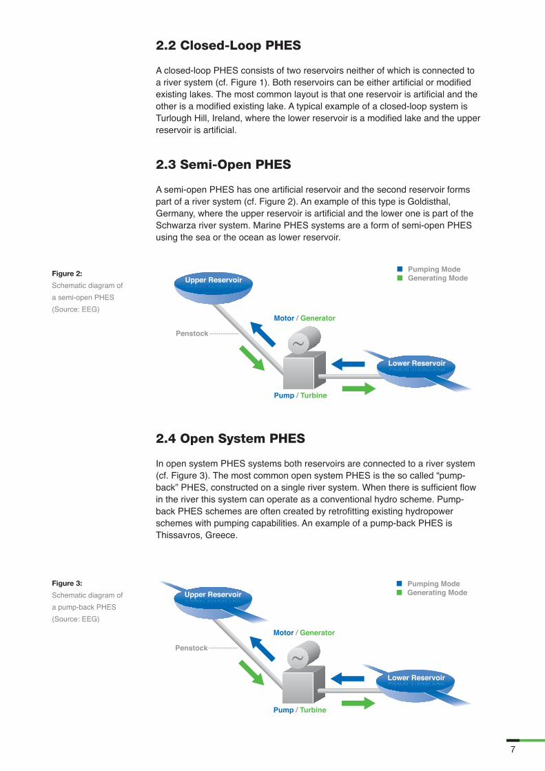
2.3 Semi-Open PHES
A semi-open PHES has one artificial reservoir and the second reservoir forms part of a river system (cf. Figure 2). An example of this type is Goldisthal, Germany, where the upper reservoir is artificial and the lower one is part of the Schwarza river system. Marine PHES systems are a form of semi-open PHES using the sea or the ocean as lower reservoir.
2.4 Open System PHES
In open system PHES systems both reservoirs are connected to a river system (cf. Figure 3). The most common open system PHES is the so called “pump-back” PHES, constructed on a single river system. When there is sufficient flow in the river this system can operate as a conventional hydro scheme. Pump-back PHES schemes are often created by retrofitting existing hydropower schemes with pumping capabilities. An example of a pump-back PHES is Thissavros, Greece.
Figure 2:
Schematic diagram of a semi-open PHES (Source: EEG)
Figure 3:
Schematic diagram of a pump-back PHES (Source: EEG)
8
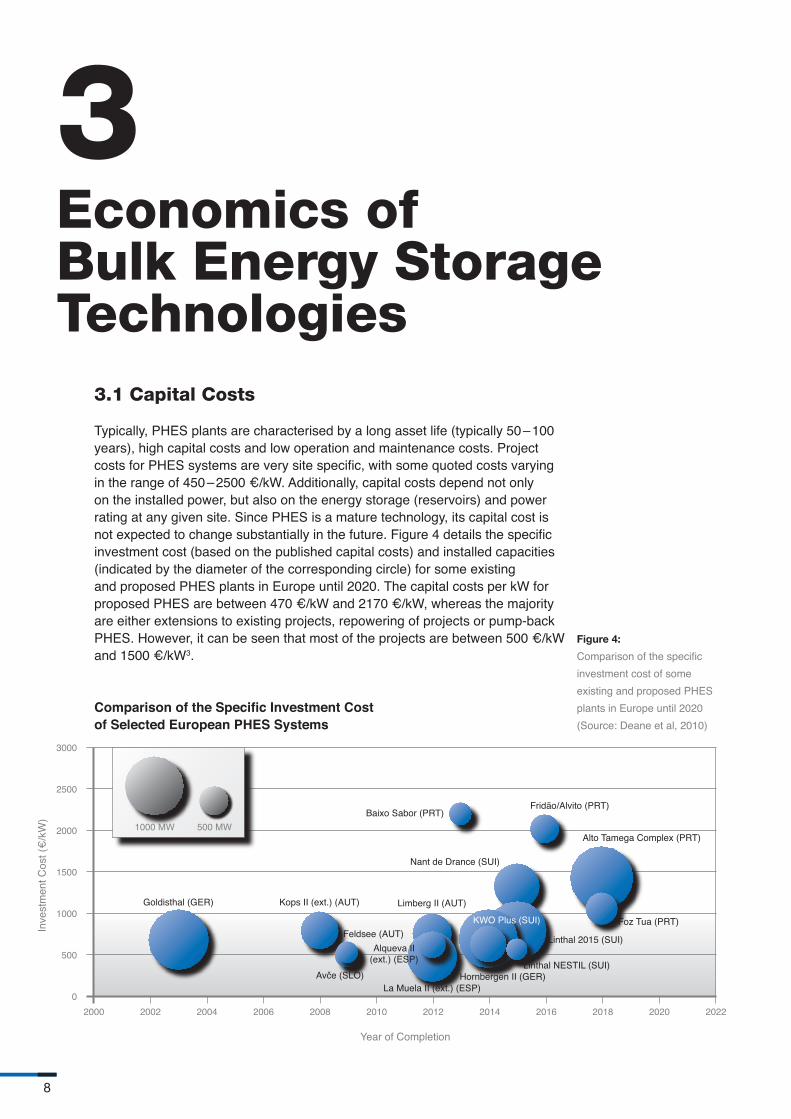
3.1 Capital Costs
Typically, PHES plants are characterised by a long asset life (typically 50 – 100 years), high capital costs and low operation and maintenance costs. Project costs for PHES systems are very site specific, with some quoted costs varying in the range of 450 – 2500 €/kW. Additionally, capital costs depend not only on the installed power, but also on the energy storage (reservoirs) and power rating at any given site. Since PHES is a mature technology, its capital cost is not expected to change substantially in the future. Figure 4 details the specific investment cost (based on the published capital costs) and installed capacities (indicated by the diameter of the corresponding circle) for some existing and proposed PHES plants in Europe until 2020. The capital costs per kW for proposed PHES are between 470 €/kW and 2170 €/kW, whereas the majority are either extensions to existing projects, repowering of projects or pump-back PHES. However, it can be seen that most of the projects are between 500 €/kW and 1500 €/kW3.
3 Economics of Bulk Energy Storage Technologies
Figure 4:
Comparison of the specific investment cost of some existing and proposed PHES plants in Europe until 2020 (Source: Deane et al, 2010)
Comparison of the Specific Investment Cost of Selected European PHES Systems
Year of Completion
Inve
stm
ent C
ost (
€/k
W)

9
A great number of existing PHES plants were built before liberalized markets by state owned utilities. Now, as the latest deployments of new PHES plants in Europe show, developers operating in liberalized markets tend to repower, enhance projects or build “pump-back” PHES rather than conventional “pure” pumped storage. This trend is partly driven by a lack of economically attractive new sites. Furthermore, repowering or enhancing existing infrastructure is less capital intensive and reduces environmental and planning issues. Repowered plants benefit from improvements in technology and design and usually use more efficient and larger turbines / pumps. “Pump-back” facilities have the advantage that their energy storage capacity is generally much greater4. PHES systems with significant hydro inflow may also operate as conventional hydroelectric generation units during times of excess inflow helping to increase the economic competitiveness of the plant (Deane et al, 2010).
3.2 Price Arbitrage
As previously mentioned, most PHES systems were built before electricity market liberalisation. Nowadays, in liberalized electricity markets, bulk energy storage projects may be remunerated through ancillary services payments, capacity payments and electricity trading. Electricity trading is usually the major source of revenue for bulk EST systems since operators may take advantage of price arbitrage opportunities. For arbitrage, the electricity price during pumping mode (in general off-peak / excess electricity, cf. Figure 5) has to be at least 20 – 30% lower than the selling price during generating mode (on-peak electricity), in order to compensate for energy losses5. This implies that significant volatility (not necessarily high energy prices) must be present in the wholesale price of electricity to generate revenue (Dena, 2010).
However, due to long construction times and high uncertainty of future electricity prices (and therefore of arbitrage opportunities) PHES systems are risky investments. On the one hand, the ongoing integration of large amounts of very variable and less predictable wind and solar (photovoltaic, PV) power into the European electricity system induces more frequent and uncertain price fluctuations at the competitive spot market due to changing in-feed. On the other hand, increasing RES-E generation can also have a negative economic effect for bulk EST. The so-called “merit order effect” (cf. Sensfuß et al, 2008) has the potential to lower the arbitrage between peak and off-peak prices in the long-term. Especially PV can lead to a price damping effect in
the midday peak, therefore lowering of the available price margin – as it was already observable in the German electricity market in the years 2010 and 2011 (Steffen, 2012).
Figure 5:
Basic principle of price arbitrage of a PHES system (Source: EEG)
3 For more details about the economics of bulk EST see Zach et al, 2012b.4 Additionally, pump-back retrofits also have lower environmental impacts from construction than alternative PHES
configurations.5 Cycle-efficiency (i.e. store and then restore electricity) of PHES systems is typically 70 – 80%, meaning 20 – 30% energy
losses.

10
As mentioned in the previous section, the potential for revenue from price arbitrage alone is not sufficient to attract investments in bulk EST, both because of the low profit margins compared to high investment costs and because of the dependence of the price difference on energy policy and regulations. However, other applications and possible revenue streams exist for bulk EST, which are briefly described in this section.
4.1 Primary, Secondary and Tertiary Control
Any imbalance between electric power generation and consumption results (in real-time) in a frequency change within the entire network of the synchronous area – i.e. a frequency deviation occurs. If the system frequency declines below 50 Hz, the total demand has been larger than the total generation. If the frequency rises above 50 Hz, the total demand has been less than the total generation. To stabilise the system frequency to 50 Hz after a sudden imbalance, the primary control reserves (also called rapid or spinning reserve) are activated, which allow a balance to be re-established at a system frequency other than the frequency set-point (see Figure 6). Primary control reserves are provided by all transmission system operators (TSO) connected to the synchronous area and have to be fully activated within max. 30 seconds after a deviation occurs (ENTSO-E, 2011).
4 Applications of Bulk Energy Storage Technologies

11
Secondary control reserve (or standing / energy imbalance reserve) is activated after 30 seconds to restore system frequency to 50 Hz within the synchronous area and to rebalance generation and consumption within each control area / block. Whereas all control areas have to provide mutual support to primary control reserve, only the control area / block affected by a power imbalance is required to undertake secondary control action for correction. Since, in practise, electricity demand varies continuously (even without forecast errors), secondary reserve is required on a continuous basis. Further on, its activation makes primary control reserve available again (ENTSO-E, 2011).
Tertiary control reserve (also called minute reserve) is typically operated in succession or, in case of larger incidents, as a supplement to secondary control reserve. Its function is to free up secondary control reserve and any primary control reserve still in use (cf. Figure 6). Total tertiary control reserve of a control area / block has to be larger than the largest expected loss of power (generation unit, power feed-in etc.) of the control block / area (ENTSO-E, 2011).
Since primary control reserve has to be capable of being activated within seconds, normally bulk EST (PHES & CAES) cannot be applied unless they are specifically designed for fast activation times (e.g. Dinorwig PHES in the United Kingdom, cf. Edison Mission Energy, 1999). Otherwise, bulk EST fit perfectly for secondary and tertiary control reserves and their provision is of great importance for bulk EST for generating additional revenues6. Due to increasing shares of RES-E generation, the prices for control reserves, especially the energy prices for negative tertiary control, have been increasing in recent years (Ehlers, 2011). Nevertheless, todays volumes of needed control power are rather small and their market is highly competitive7.
Figure 6:
Principal of frequency deviation and subsequentactivation of reserves (Source: ENTSO-E, 2011)
6 Different remuneration schemes exist in the EU for the provision of control power / ancillary services, e.g. bilateral contracts, spot market and tendering (Ruester et al, 2012).
7 For more details about control power markets see Zach et al, 2012c.
Frequency Deviation
Primary Control Reserve
Secondary Control Reserve
Tertiary Control Reserve(directly activated / scheduled)

12
4.2 Blackstart Capability
Blackstart is the ability of a power plant / electricity system to start-up and provide necessary power to re-energise the grid and start other power generating systems without the use of an external power resource after a complete power outage or islanding situation. Only power plants with no or very low start-up energy needs (e.g. provided by diesel engine / generator etc.) have the ability of a blackstart. Another important feature of a blackstart-compatible power plant is its flexible controllability, which allows it to cope with demand variations when new loads are connected. Bulk EST are well-suited technologies for this kind of services, they can be awarded to perfectly incorporate the functionality of blackstart capability. However, no market exists for blackstart capability, but in some countries there is a remuneration scheme for this service (Ruester et al, 2012).
4.3 Transmission and Distribution Investment Deferral
The avoidance of the use of transmission and generation resources during peak-load hours contributes to transmission investment deferral – e.g. delay of new constructions and upgrades of connection lines, transformers, stations, etc. This can be achieved by installing EST units (bulk EST in particular) near load. This reduces losses and increases efficiency, lowering the need for bulk transfers and peak outtakes and finally reducing the use of transmission lines (cf. Denholm et al, 2009)8. However, this service9 is not remunerated but it represents an additional benefit for the electricity system.
4.4 Management of RES-E
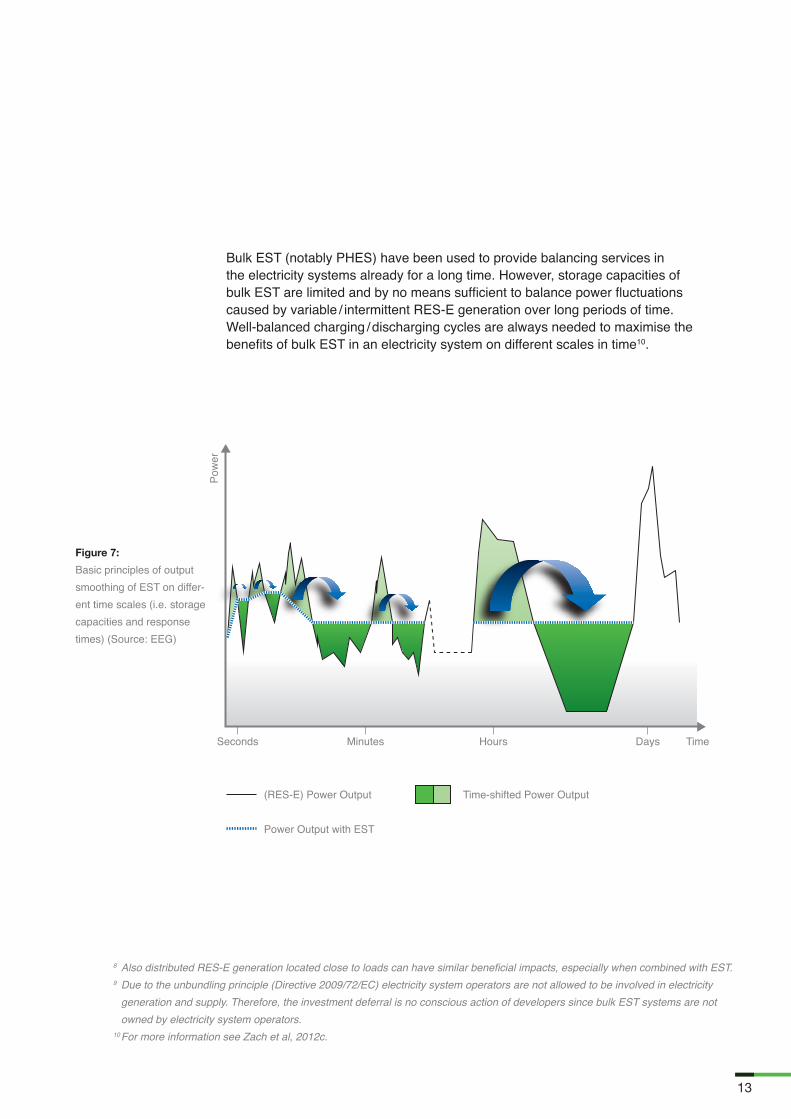
Bulk EST can enable firming up and backup of variable / intermittent RES-E generation to allow for extended periods of low electricity generation which typically characterises patterns of wind and / or PV generation. This also allows RES-E generation to take advantage of daily load patterns, enabling them to shift generation in time (cf. Figure 7) and, furthermore, to capitalise higher peak load prices. Unlike thermal power plants, bulk EST systems can help fully utilising future RES-E generation by storing excess RES-E generation (e.g. this electricity might be available at low cost for pumping purposes in a PHES system) and “restoring” it when needed.
Moreover, the high flexibility of bulk EST, i.e. fast ramping rates and the ability to switch from electricity consumption to electricity generation (and vice versa) within a very short time period, make them highly suitable for balancing short term fluctuations of intermittent RES-E generation (e.g. wind and PV). Therefore, especially intraday markets (e.g. trading hourly- and 15-minutes-contracts) could be very profitable in case of forecast errors / high drop-off rates of RES-E generation (or electricity demand).
13
Bulk EST (notably PHES) have been used to provide balancing services in the electricity systems already for a long time. However, storage capacities of bulk EST are limited and by no means sufficient to balance power fluctuations caused by variable / intermittent RES-E generation over long periods of time. Well-balanced charging / discharging cycles are always needed to maximise the benefits of bulk EST in an electricity system on different scales in time10.
8 Also distributed RES-E generation located close to loads can have similar beneficial impacts, especially when combined with EST.9 Due to the unbundling principle (Directive 2009/72/EC) electricity system operators are not allowed to be involved in electricity
generation and supply. Therefore, the investment deferral is no conscious action of developers since bulk EST systems are not owned by electricity system operators.
10 For more information see Zach et al, 2012c.
Figure 7:
Basic principles of output smoothing of EST on differ-ent time scales (i.e. storage capacities and response times) (Source: EEG)
(RES-E) Power Output
Power Output with EST
Time-shifted Power Output

14
This chapter provides an overview on the possible contribution of bulk EST in future European electricity systems. For this, the geographic allocation of future potentials of bulk EST are identified and are matched with the spatial dispersion of future RES-E deployment and the existing thermal power plant-portfolio on regional level in Europe. Selected results for the years 2030 and 2050 for two different RES-E deployment scenarios are also shown11.
5.1 Pumped Hydro Energy Storage in European Context
First, the geographical allocation of future potentials of bulk EST across Europe is identified. The estimation of the future potential of bulk EST implementation is based on a summary and synthesis of the most relevant existing work, studies and modelling results on this topic (on country level as well as on European level).
Figure 8 shows that the highest total potentials for (P)HES are located in parts of Scandinavia, Central and Western Europe. Besides Norway and Sweden, European countries in mountainous areas, such as the Alps and the Pyrenees, have significant potential for deployment of PHES systems. Particularly Luxembourg, Switzerland and Austria have a very high PHES potential in relation to their land area. On the contrary, countries with a rather flat landscape like Denmark, Finland, Latvia and the Netherlands have no existing (P)HES power plants and also no development plans for new PHES systems at the moment12.
For purpose of our analyses, two different future RES-E deployment scenarios in European countries for the years 2030 and 2050 have been developed based on modelling results derived from the Green-X RES-Electricity deployment simulation tool (Huber et al, 2004). Green-X provides future scenarios on
5 Contribution of Pumped Hydro Energy Storage in Future European Electricity Systems

15
annual RES-E capacities installations and electricity generation per country under a variety of different possible policy settings and constraints. The two generated scenarios are, on the one hand a business-as-usual scenario (BAU) with moderate increase of RES-E deployment and an environmentally friendly scenario (GREEN) with high increase of RES-E deployment in Europe, on the other hand.
Taking into account the physical constraints in the European (cross-border) transmission grid in the analysis, European countries were clustered into nine different electricity market regions according to the different wholesale electricity market places / prices (as a consequence of physical constraints in the transmission grid). This clustering coincides with relevant EC documents (EC, 2007) and (EC, 2010) (e.g. EC infrastructure package) and the ENTSO-E’s “Ten Year Network Development Plan (TYNDP)” (ENTSO-E, 2010) and is also shown in Figure 8.
Figure 8:
(P)HES potential in Europe until the year 2050 in power capacity per country (left) and clustering of countries to nine different European electricity market regions (right) (Source: EEG)
(P)HES Potential 2050
0 GW0 – 1 GW1 – 2 GW2 – 5 GW5 – 10 GW10 – 15 GW15 – 30 GW
11 For more details about the analysis and further results see Zach et al, 2012a.12 No data is available for Albania.

16
5.2 Comparison of Selected Results
In order to be able to estimate the possible direct benefits and future contribution of bulk EST implementation to balance an incumbent regional electricity system, the identified bulk EST potentials are matched with the spatial dispersion of future RES-E deployment and the existing thermal power plant-portfolio on regional level in Europe. Doing this, the residual load curves of the nine different regions for the years 2030 and 2050 and for two different scenarios (BAU and GREEN) were derived and the possible coverage of the residual load curves with existing thermal power plants and bulk EST was analysed.
Selected results of the BAU scenario in the year 2030 and of the GREEN scenario in the year 2050 are shown for the Europe region, combining the results of all nine analysed regions13.
5.2.1 BAU Scenario 2030Figure 9 shows the load duration, residual load curve and coverage of the residual load of the Europe region with existing thermal power plants and PHES in the BAU scenario in the year 2030. In general, the residual load curves (purple line in Figure 9) were generated by subtracting hourly PV (yellow area), wind (dark blue area), other renewables (green area) and run-of-river hydro (light blue area) electricity generation from the load duration curve (black line). Note, that after every subtraction of respective RES-E feed-in from the load, the residual load curve is sorted again from highest to lowest residual load values. Therefore, a vertical cross-section from the load curve to the residual load curve does not determine RES-E feed-in at a certain point in time simply because it represents RES-E feed-in data from different points in time.
After their establishment, the residual load curves for the years 2020, 2030 and 2050 were “filled-up” with the still existing14 thermal power plant capacities (cf. Figure 9). The thermal power plant capacities are drawn as constant bands, starting with the base-load and least-costly power plants (i.e. nuclear, lignite and coal) followed by gas and oil power plant capacities.
Additionally, existing installed capacities of (P)HES systems in the respective region are depicted as constant bands indicated downward from the top of the residual load curves in order to show their potential for providing peak-load power. Any available additional PHES potentials (currently not implemented) within the region are indicated by a blue dotted line (cf. Figure 9). The electricity consumption of existing and future PHES systems in pumping mode is not incorporated in the residual load curves. However, in general this additional demand would only alter the residual load values in times of high RES-E feed-in / low residual load (i.e. right side of the residual load curve).
Figure 9:
Load duration, residual load curve and coverage of the residual load of the Europe region with existing thermal power plants and PHES in the BAU scenario in the year 2030 (Source: EEG)
Load Duration CurvePVWindOther RenewablesRun-of-River HydroResidual LoadExisting (P)HESGap
Full-Load Hours [h]
Europe 2030 BAU-ScenarioIn
stal
led
Cap
acity
[GW
]
17
In many analysed regions and time horizons a gap (indicated in white colour) remains between the PHES band and the upper band of the thermal power plants, meaning that there is not enough installed power plant capacity available within the region to meet regional electricity demand.
It can be seen that in the Europe region a capacity gap of about 100 GW remains in the year 2030 in the BAU scenario, meaning that new thermal and / or PHES power plants will be needed to cover electricity demand in this scenario15. The blue dotted line indicates that only a minor part of this missing capacity could be provided by new, currently not utilized PHES systems in the European region. Yet, in some of the nine analysed regions (e.g. Baltic region, Central Western and South Eastern Europe) new PHES systems could have major contributions in filling this gap.
Furthermore, in some regions (e.g. Iberian Peninsula and Italy) sufficient (thermal) power plant capacity is available in the region (i.e. no capacity gap between supply and demand). This fact has two reasons: On the one hand, high RES-E deployment in the regions (especially wind, but also PV) and, on the other hand, large amounts of still existing thermal power plants in the year 2030 (due to high investments in gas-fired thermal power plants in the last ten years in the regions).
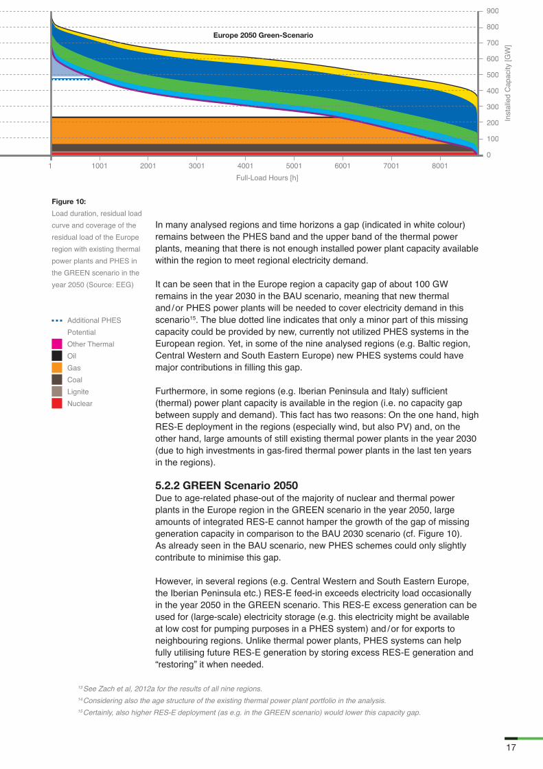
5.2.2 GREEN Scenario 2050Due to age-related phase-out of the majority of nuclear and thermal power plants in the Europe region in the GREEN scenario in the year 2050, large amounts of integrated RES-E cannot hamper the growth of the gap of missing generation capacity in comparison to the BAU 2030 scenario (cf. Figure 10). As already seen in the BAU scenario, new PHES schemes could only slightly contribute to minimise this gap.
However, in several regions (e.g. Central Western and South Eastern Europe, the Iberian Peninsula etc.) RES-E feed-in exceeds electricity load occasionally in the year 2050 in the GREEN scenario. This RES-E excess generation can be used for (large-scale) electricity storage (e.g. this electricity might be available at low cost for pumping purposes in a PHES system) and / or for exports to neighbouring regions. Unlike thermal power plants, PHES systems can help fully utilising future RES-E generation by storing excess RES-E generation and “restoring” it when needed.
13 See Zach et al, 2012a for the results of all nine regions.14 Considering also the age structure of the existing thermal power plant portfolio in the analysis.15 Certainly, also higher RES-E deployment (as e.g. in the GREEN scenario) would lower this capacity gap.
Additional PHES PotentialOther ThermalOilGasCoalLigniteNuclear
Europe 2050 Green-Scenario
Inst
alle
d C
apac
ity [G
W]
Full-Load Hours [h]
Figure 10:
Load duration, residual load curve and coverage of the residual load of the Europe region with existing thermal power plants and PHES in the GREEN scenario in the year 2050 (Source: EEG)

18
The contribution of possible future transmission grid expansion between neighbouring European electricity market regions for better matching variable / intermittent wind generation and bulk EST / other flexible electricity generation technologies (e.g. balancing “stressed” continental European electricity systems with bulk storage energy from PHES from the Alps and Scandinavia) is qualitatively discussed in Figure 11. Furthermore, the contribution of existing and new PHES and flexible thermal power plant units within a region and the management of extreme weather events within a region and between regions are assessed.
Due to a lack of available (flexible) power plant capacities in the future, the Central Western Europe (CWE) region can hardly contribute to balancing services in neighbouring regions, even in case of significant transmission grid expansion (cf. red export-arrows of the CWE region in Figure 11). However, imports from the Nordic region, the Iberian Peninsula and also Italy could help mitigating the effects of intermittent RES-E generation in the CWE region in case of significant transmission grid expansion and negative correlation of wind. In case of moderate transmission grid expansion or positive correlation of wind between the regions, the contribution from these regions is limited (cf. yellow-green import-arrows of the CWE region in Figure 11). Also imports of flexibility from the Central Eastern Europe (CEE), Western Balkan and UK & Ireland region are only limited (even in case of significant transmission grid expansion and negative correlation of wind, cf. yellow import-arrows of the CWE region in Figure 11).
The CEE region is very similar to the CWE region in terms of possible contribution to neighbouring electricity regions, as it also has only limited capability. The region could profit from Nordic, South-Eastern Europe (SEE) and Western Balkan PHES capacities in case of significant transmission grid expansion and negative correlation of wind.
Because of its vast amounts of flexible (P)HES systems, the Nordic region could contribute to balance neighbouring European regions in case of significant transmission grid expansion and negative correlation of wind. If additional generation capacities are needed, UK & Ireland could contribute with their flexible thermal power plant portfolio.
6 Role of Cross-Border Transmission Grid Expansion and Extreme Weather Events

19
Since the Iberian Peninsula is located on the outer edge of the European electricity system, its importing / exporting capabilities from / to neighbouring regions are limited. However, in case of significant transmission grid expansion to the CWE region, the Iberian Peninsula could export flexibility from gas-fired thermal power plant / PHES units.
For the remaining European electricity market regions the following can be observed: Since Italy’s electricity system is very similar to the Iberian Peninsula’s (i.e. high shares of gas-fired thermal power plants and PHES systems), Italy could export flexibility to CWE and the Western Balkan region. Vice versa, the Western Balkan region could only provide limited flexibility to Italy and other neighbouring regions. Because of high shares of PHES capacities in its electricity system, also the South Eastern Europe region could export flexibility to its neighbouring regions. On the contrary, due to low overall installed power plant capacities, the Baltic region’s flexible power plant portfolio is only of minor importance in a European context. In the UK & Ireland region PHES systems will have a little contribution to the electricity system only, because of low future PHES potentials. Nevertheless, the UK & Ireland region could provide flexibility from gas-fired thermal power plant units to neighbouring regions.
In general, it can be observed that existing and new PHES and flexible thermal power plant units are strongly needed in the majority of the European electricity regions to cope with the effects of variable RES-E feed-in16. Only in the Iberian Peninsula and Italy sufficient (flexible) power plant capacity is already in the electricity system, thanks to high investments in new gas-fired thermal power plants in the last 10 years and also due to high amounts of already implemented PHES schemes.
16 Certainly, also other technology options are qualified to increase the flexibility of future electricity systems, e.g. demand side management, dispatchable RES-E technologies and combined heat and power plants etc. See Zach et al, 2012c for more details.
Figure 11:
Contribution of transmission grid expansion for mitigation of wind within the regions (Source: EEG)
Flexibility Provision
Imports / Exports
LowLimitedHigh

20
7
Conclusions / Outlook

21
This document provides an overview on the possible contribution of bulk EST in facilitating large-scale expansion of RES-E generation in Europe.
Currently, PHES systems are the most mature and widely used EST. However, due to long construction times and high uncertainty of future electricity price developments (and therefore price arbitrage opportunities) PHES systems are risky investments. Furthermore, their deployment potential is constraint across Europe, since PHES systems are strongly dependent on certain geographic requirements and topographical conditions. Therefore, most of the currently proposed new PHES plants are either extensions or upgrades / repowering of existing storage and / or PHES power plants. The major applications and revenue streams for bulk EST are expected to be management of variable / intermittent RES-E generation and energy price arbitrage, i.e. storing RES-E generation in off-peak hours and restoring it again in on-peak hours. Also the provision of secondary and tertiary control reserve is a possible and profitable application for bulk EST. Several other possible applications for bulk EST – like blackstart capability and transmission and distribution investment deferral – are also briefly outlined in this document.The analysis summarized in this document has focussed on the possible direct benefits and the possible future contribution of bulk EST implementation to balance an incumbent regional electricity system in Europe. This means that bulk EST potentials were identified and matched with the spatial dispersion of future RES-E deployment and the existing thermal power plant-portfolio on regional level in Europe. Selected results on European level were shown combining the results of all nine analysed European regions, for the years 2030 and 2050 for two different scenarios.
Due to age-related phase-out of thermal power plants in the future additional new power plant capacities are needed in many electricity regions already by the year 2030. These gaps of electricity generation capacity can be either filled up with new PHES systems (as far as additional potential is available in the region) or new flexible thermal power plants.
Only some European regions have sufficient flexible generation capacity (gas power plants and PHES systems) available in the system to cover the residual load also in the long-term (due to large investments in gas-fired power plants in the last ten years). Furthermore, in the GREEN scenario RES-E feed-in exceeds electricity demand for some time of the year 2050 in several of the analysed regions. This excess RES-E generation can be used for (large-scale) electricity storage and / or for exports to neighbouring European regions. Because of its vast amounts of flexible (P)HES systems, especially the Nordic region could significantly contribute to balance the electricity systems of neighbouring regions in case of significant transmission grid expansion and negative correlation of wind between the regions.
In general, it can be observed that existing and new PHES (and additional flexible thermal power plant units) are strongly needed in almost all of the European electricity market regions to (partly) cover the future electricity generation gap. Unlike fossil fuel-fired thermal power plants, PHES systems can provide flexibility without additional CO2 emissions and can help fully utilising future RES-E generation.

22
• Deane et al: “Techno-economic review of existing and new pumped hydro energy storage plant”, Renewable and Sustainable Energy Reviews 14, 2010
• Denholm et al: “The value of compressed air energy storage with wind in transmission-constrained electric power systems”, Energy Policy 37(8), 2009
• Deutsche Energie Agentur (Dena): “Analyse der Notwendigkeit des Ausbaus von Pumpspeicher-werken und anderen Stromspeichern zur Integration der erneuerbaren Energien (Kurz: PSW – Integration EE)“, final report, 2010
• Edison Mission Energy: “Dinorwig: The Electric Mountain“, Brochure, 1999
• Ehlers: “Strommarktdesign angesichts des Ausbaus fluktuierender Stromerzeugung”, Dissertation, Fakultät III – Prozesswissenschaften der Technischen Universität Berlin, 2011
• ENTSO-E: “Operation Handbook: P1 - Policy 1: Load-Frequency Control and Performance”, https://www.entsoe.eu/fileadmin/user_upload/_library/publications/entsoe/Operation_Handbook/Policy_1_final.pdf, 2011
• ENTSO-E: “Pilot Ten-Year Network Development Plan (TYNDP)”, Executive Summary 2010, downloadable at https://www.entsoe.eu/fileadmin/user_upload/_library/SDC/TYNDP/100630_TYNDP_Executive_Summary.pdf, 2010
• EPRI (Electric Power Research Institute): “Electric Energy Storage Technology Options – A Primer on Applications, Costs & Benefits”, EPRI Executive Summary (1022261), 2010
• EURELECTRIC: “Hydro in Europe: Powering Renewables”, full report, downloadable at: http://www.eurelectric.org, 2011
• European Commission (EC): “Energy infrastructure priorities for 2020 and beyond – A Blueprint for an integrated European energy network”, Communication from the Commission – COM(2010) 677/4, 2010
• European Commission (EC): “Priority Interconnection Plan”, Communication from the Commission – COM(2006) 846 final/2, 2007
• Huber et al: “Action plan for a dynamic RES-E policy”, Report of the European research project Green-X – funded by the EC-DG Research, Vienna University of Technology, 2004
• Ruester et al: “Electricity Storage: How to Facilitate its Deployment and Operation in the EU”, Final Report of topic 8 of the project “THINK”, ISBN: 978-92-9084-087-9, 2012
• Sensfuß et al: “The merit-order effect: A detailed analysis of the price effect of renewable electricity generation on spot market prices in Germany”, Energy Policy 36 (2008) 3086– 3094, 2008
• Steffen: “Prospects of pumped-hydro storage in Germany”, Energy Policy (2012), 2012
• Zach et al: “Contribution of Bulk Energy Storage in Future Electricity Systems Facilitating Renewable Energy Expansion”, Deliverable 2.3 of the project “stoRE”, available at: www.store-project.eu, 2012a
• Zach et al: “Report Summarizing the Current Status, Role and Costs of Energy Storage Technologies”, Deliverable 2.1 of the project “stoRE”, available at: www.store-project.eu, 2012b
• Zach et al: “Role of Bulk Energy Storage in Future Electricity Systems with High Shares of RES-E Generation”, Deliverable 2.2 of the project “stoRE”, available at: www.store-project.eu, 2012c
8
References

23
List of Abbreviations
(P)HES (Pumped) Hydro Energy Storage – i.e. conventional HES as well as PHESBAU Business-As-UsualCAES Compressed Air Energy StorageCEE Central Eastern Europe (i.e. Poland, Czech Republic, Slovakia, Hungary)CWE Central Western Europe (i.e. France, the Netherlands, Luxembourg,
Belgium, West Denmark, Germany, Switzerland and Austria)CO2 Carbon DioxideEC European CommissionEEG Energy Economics GroupENTSO-E European Network of Transmission System Operators for ElectricityEST Electricity Storage TechnologyEU European UnionGW Giga WattHz HertzHES Hydro Energy Storage (dam- or barrage-hydro power plant)kW Kilo WattMW Mega WattMWh Mega Watt HourPHES Pumped Hydro Energy StoragePV PhotovoltaicsRES-E Renewable Energy Sources for Electricity generationSEE South-Eastern Europe (i.e. Romania, Bulgaria and Greece)TSO Transmission System OperatorTWh Tera Watt HourTYNDP Ten Year Network Development Plan (ENTSO-E)UK The United Kingdom

This report has been produced as part of the project “Facilitating energy storage to allow high penetration of intermittent renewable energy”, stoRE. The logos of the partners cooperating in this project are shown above and more information about them and the project is available on www.store-project.eu