THE RIGAKU JOURNAL VOL. 7 / NO. 1 / 1990 Technical Note · is widely used as it allows handy...
9
Vol. 7. No. 1 1990 27 THE RIGAKU JOURNAL VOL. 7 / NO. 1 / 1990 Technical Note SINGLE CRYSTAL ORIENTATION MEASUREMENT BY X-RAY METHODS T. Kikuchi Rigaku Corporation, Tokyo, Japan. Semiconductor substrates made from single crystal materials need to be cut precisely along a fixed axis during the manufac- turing process of the semiconductor components. Thus, measuring the crystal orientation is critical. For these measurements, X- ray techniques demonstrate the highest precision. This report presents an outline of two popular X-ray diffraction techniques, the diffractometer and the Laue methods. 1. Introduction Cutting a single crystal in various directions and comparing its mechanical, optical, electrical and magnetic properties reveals differences in the respective properties as a result of the direction of the cut. Recent industries take advantage of such crystal characteristics and produce semiconductor components having a variety of functions. To pro- duce components of uniform quality and stability, it is essential to cut the crystals along a fixed ori- entation. Hence measurement of crystal orienta- tion has become important from an engineering viewpoint. Generally, orientation measurement means determination of the arrangement of the major crystal axes with respect to the coordinates that represent the external form of the crystal. How- ever, in the case of a crystal artificially grown with a seed crystal, its orientation can be distinctly known from the external form through the natural surface and the crystal habit line. In this case the aim of orientation measurement is to determine the direction of normal to the prescribed plane. To distinguish this from orientation measurement in general, it is hereafter referred to as planar orien- tation measurement. The orientation measurement methods are: optical etching, and X-ray/electron diffraction. Among them, measurement by X-ray diffraction is widely used as it allows handy operation yet high precision. The X-ray method is divided fur- ther into the diffractometer method, the Laue method and so on. Outlined in this report are planar orientation measurement by the diffractometer method, and also as general orientation measurement methods, the diffractometer method employing a four-circle goniometer and the Laue method. 2. Planar Orientation Measurement of Sin- gle Crystals with X-rays 2. 1 X -ray Diffraction due to a Crystal The atoms in a crystal are three-dimensionally arranged in a periodically repeated pattern form- ing space lattices. There are innumerable planes that contain each lattice point of these space lat- tices (known as a lattice plane), and they are con- sidered to overlap with each other in a layer form at a certain interval. When the crystal is irradiated with X-rays having a wavelength equivalent to or slightly smaller than the interatomic distance, the lattice plane serves as a grating so that X-rays will be scattered (diffracted) intensely toward a par- ticular direction [1]. The conditions for X-ray diffraction from a crystal may be summarized as follows. (1) The incidence angle and reflection angle of X-rays with respect to the lattice plane are identical (mirror face reflection). (2) The incident X-ray beam, diffracted X-ray beam and the normal to the lattice plane are in the same plane. (3) X-rays will be diffracted only when they are incident on the lattice plane at a specific angle θ that satisfies the Bragg equation 2dsin θ=λ (1) where d is interplanar spacing and λ is an X-ray wavelength. For orientation measurement, CuKα at λ = 1.54 Å is usually employed. The angle θ is called the Bragg angle. (4) While the lattice plane can be represented by the Miller indices (h k l), it does not necessar- ily follow that every lattice plane will cause dif- fraction. For instance, in the case of diamond structured Si crystals, no diffraction will result if the Miller indices h, k, and l are a mixture of odd
Transcript of THE RIGAKU JOURNAL VOL. 7 / NO. 1 / 1990 Technical Note · is widely used as it allows handy...
Vol. 7. No. 1 1990 27
THE RIGAKU JOURNAL VOL. 7 / NO. 1 / 1990
Technical Note
SINGLE CRYSTAL ORIENTATION MEASUREMENT BY X-RAY METHODS
T. Kikuchi Rigaku Corporation, Tokyo, Japan. Semiconductor substrates made from single crystal materials need to be cut precisely along a fixed axis during the manufac-turing process of the semiconductor components. Thus, measuring the crystal orientation is critical. For these measurements, X-ray techniques demonstrate the highest precision. This report presents an outline of two popular X-ray diffraction techniques, the diffractometer and the Laue methods.
1. Introduction Cutting a single crystal in various directions
and comparing its mechanical, optical, electrical and magnetic properties reveals differences in the respective properties as a result of the direction of the cut. Recent industries take advantage of such crystal characteristics and produce semiconductor components having a variety of functions. To pro-duce components of uniform quality and stability, it is essential to cut the crystals along a fixed ori-entation. Hence measurement of crystal orienta-tion has become important from an engineering viewpoint.
Generally, orientation measurement means determination of the arrangement of the major crystal axes with respect to the coordinates that represent the external form of the crystal. How-ever, in the case of a crystal artificially grown with a seed crystal, its orientation can be distinctly known from the external form through the natural surface and the crystal habit line. In this case the aim of orientation measurement is to determine the direction of normal to the prescribed plane. To distinguish this from orientation measurement in general, it is hereafter referred to as planar orien-tation measurement.
The orientation measurement methods are: optical etching, and X-ray/electron diffraction. Among them, measurement by X-ray diffraction is widely used as it allows handy operation yet high precision. The X-ray method is divided fur-ther into the diffractometer method, the Laue method and so on.
Outlined in this report are planar orientation measurement by the diffractometer method, and also as general orientation measurement methods, the diffractometer method employing a four-circle goniometer and the Laue method.
2. Planar Orientation Measurement of Sin-gle Crystals with X-rays
2. 1 X -ray Diffraction due to a Crystal The atoms in a crystal are three-dimensionally
arranged in a periodically repeated pattern form-ing space lattices. There are innumerable planes that contain each lattice point of these space lat-tices (known as a lattice plane), and they are con-sidered to overlap with each other in a layer form at a certain interval. When the crystal is irradiated with X-rays having a wavelength equivalent to or slightly smaller than the interatomic distance, the lattice plane serves as a grating so that X-rays will be scattered (diffracted) intensely toward a par-ticular direction [1].
The conditions for X-ray diffraction from a crystal may be summarized as follows.
(1) The incidence angle and reflection angle of X-rays with respect to the lattice plane are identical (mirror face reflection).
(2) The incident X-ray beam, diffracted X-ray beam and the normal to the lattice plane are in the same plane.
(3) X-rays will be diffracted only when they are incident on the lattice plane at a specific angle θ that satisfies the Bragg equation
2dsin θ=λ (1) where d is interplanar spacing and λ is an X-ray wavelength. For orientation measurement, CuKα at λ = 1.54 Å is usually employed. The angle θ is called the Bragg angle.
(4) While the lattice plane can be represented by the Miller indices (h k l), it does not necessar-ily follow that every lattice plane will cause dif-fraction. For instance, in the case of diamond structured Si crystals, no diffraction will result if the Miller indices h, k, and l are a mixture of odd
The Rigaku Journal 28
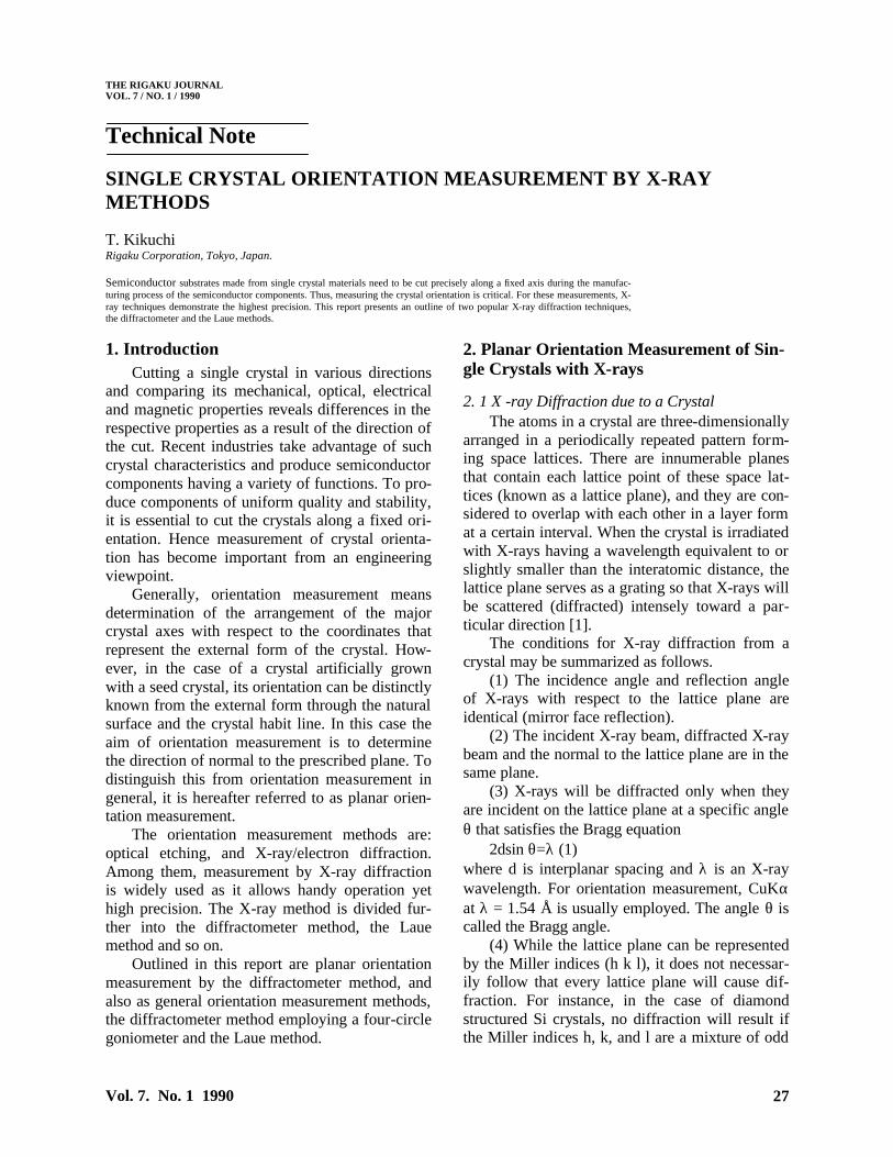
Fig. 1 X-ray optical system.
and even numbers. Moreover, even in the case of no such mixture, no diffraction will be caused if h+k+l=4m+2 (m: integer). This is the extinction rule which depends on the type of crystal. Table 1 shows the plane indices, d-values and Bragg an-gles of diffraction from a Si crystal. For instance, when the (1 0 0) orientation is to be determined, (4 0 0), which is parallel to it, is used as the dif-fracting plane.
2.2 X -ray Optical System Fig. 1 shows the X-ray optical system for the
planar orientation measurement. This system is called an X-ray diffractometer. An orientation measuring method using the system is referred to as the diffractometer method.
An X-ray beam emitted from an X-ray source (in the form of point or line) is directed to the sample by a slit. A Cu-target tube is generally used as the X-ray source. The X-rays emitted con-sist of a continuous X-ray component and a char-acteristic X-ray component of narrow width hav-ing a markedly high intensity. The characteristic X-rays are composed of Kα rays and Kβ rays
which have a peak intensity of about 1/5 of the Kα rays. This characteristic radiation is mono-chromatized to quasi-Kα rays by means of a Ni filter. The sample piece rotates around the rota-tional axis in the plane of the paper so that the X-ray incidence angle W, with respect to the crystal surface can be read. This device, known as a go-niometer, can read angles with a precision of 10 seconds or so. Diffraction occurs when the X-rays incident on the lattice plane at an angle θ are re-flected from the planes at an angle 2θ with respect to the incident beam. An X-ray detector is posi-tioned relative to the diffraction angle to monitor the diffracted X-ray intensity through the deflec-tion of the meter needle, etc.
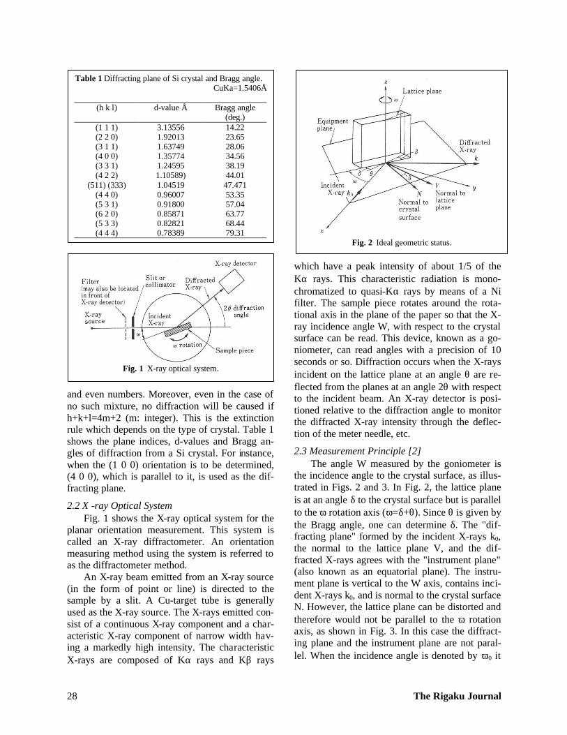
2.3 Measurement Principle [2] The angle W measured by the goniometer is
the incidence angle to the crystal surface, as illus-trated in Figs. 2 and 3. In Fig. 2, the lattice plane is at an angle δ to the crystal surface but is parallel to the ω rotation axis (ω=δ+θ). Since θ is given by the Bragg angle, one can determine δ. The "dif-fracting plane" formed by the incident X-rays k0, the normal to the lattice plane V, and the dif-fracted X-rays agrees with the "instrument plane" (also known as an equatorial plane). The instru-ment plane is vertical to the W axis, contains inci-dent X-rays k0, and is normal to the crystal surface N. However, the lattice plane can be distorted and therefore would not be parallel to the ω rotation axis, as shown in Fig. 3. In this case the diffract-ing plane and the instrument plane are not paral-lel. When the incidence angle is denoted by ω0 it
Table 1 Diffracting plane of Si crystal and Bragg angle. CuKa=1.5406Å
(h k l) d-value Å Bragg angle
(deg.) (1 1 1) 3.13556 14.22 (2 2 0) 1.92013 23.65 (3 1 1) 1.63749 28.06 (4 0 0) 1.35774 34.56 (3 3 1) 1.24595 38.19 (4 2 2) 1.10589) 44.01
(511) (333) 1.04519 47.471 (4 4 0) 0.96007 53.35 (5 3 1) 0.91800 57.04 (6 2 0) 0.85871 63.77 (5 3 3) 0.82821 68.44 (4 4 4) 0.78389 79.31
Fig. 2 Ideal geometric status.

Vol. 7. No. 1 1990 29
is given by ω0=θ0+δ1 (2)
where θ is the virtual Bragg angle and is related to the true Bragg angle by Eq. (3) [3].
22
12
1
10
tantan1cossin
coscossin
sin
δδδθ
δδθ
θ
++=
= (3)
If measurements are made without compensating for the possibility of a lattice plane distortion, the result could be erroneous.
To measure ω180, a 180° rotation (represented by φ is made around the normal to the crystal sur-face. ω180 is given by
ω180 = θ0-δ1 (4) Eliminating θ0 from Eq. (2) and Eq. (4) yields Eq. (5)
δ1=(ω0-ω180)/2 (5) Likewise, δ2, an angle in the direction orthogonal to δ1 in Eq. (6), ω90 and ω270 are directly related to 90° and 270° in terms of φ
δ2=(ω90-ω270)/2 (6) Further, from Fig. 4, the maximum angle is achieved by
tan2δ = tan2δ1 + tan2δ2 (7) When δ1 and δ2 are not more than several degrees, δ2=δ1
2+δ22 holds, thereby determining the inclina-
tion and the direction of inclination ψ of the lat-tice
2.4 Configuration and Operation of X-ray Single Crystal Flat Plane Orientation Measuring Unit
Fig. 5 and Fig. 6 respectively show an overall view of the unit and part of the goniometer. Two measuring systems are arranged opposite each other, sharing one X-ray tube. An X-ray control section and amplifiers for detectors are incorpo-rated in a cabinet at the lower side. The X-ray tube has a forced air cooling system and allows easy installation, provided a 100V AC power sup-ply is available. Further explanation of the com-ponents is contained in Fig. 6. X-rays generated from the X-ray tube located within a shield box are directed to the sample by a slit. An X-ray shut-ter control is provided to shut off the X-rays. For safety, the X-ray shutter is designed to be of a dual system consisting of an insertion type sub-shutter at the shield box exit and a main shutter, which opens and closes being interlocked with the X-ray-proof protector.
A sample pedestal can be mounted and re-moved on the ω rotary plate. Fig. 6 shows a model
Fig. 3 General geometric status.
Fig. 4 Maximum inclination.
Fig. 5 X-ray single crystal planer orientation measure-ment unit (piezo goniometer).

The Rigaku Journal 30
for wafer samples, which is designed to press the sample against a precision polished reference plane. A grid on the reference plane serves as a guide for 90° rotation of the wafer in the plane. A variety of sample pedestals are available accord-ing to the purpose of measurement, such as a vac-uum chuck, sample holders for interplanar rota-tion, tilting, ingot, etc.
The ω rotation is made by handle operation, and the rotation angle is displayed either in de-grees or time. The X-ray detector is mounted on the 2θ rotary plate and can be set to maximize the X-ray intensity by means of a scale and index. The FWHM of a diffraction profile obtained in this manner is approximately 4' for Si(111) and the repeated angular reproducibility is about 30".
The following describes the practice of meas-uring artificial quarts and Si crystals.
2.4.1 Practice of orientation measurement in the case of quartz plates
An artificial quartz AT plate used for the os-cillator [4] has approximately a 35° angle from the Z-axis around the X-axis and approximately a 3° angle with respect to the r plane. The angular tol-erance is as strict as ±1', and since angular devia-tions occur during the process of cutting and pol-ishing, it is difficult to achieve. Routine sorting by inspection makes measurement in four directions at 90° each in the plane, inefficient and unrealis-tic. Instead, prior to cutting quartz plates, the quartz material is finished to a bar crystal having definite X and Z planes called the lumbered
quartz. This step makes it possible to work on δ2 in Fig. 3 to within ±30' even when estimated on the higher values side [5]. Now, let us assume δ1, δ2 and θ are 3°, 30', and 13.33° respectively and calculate ∆θ=θ0-θ through Eq. (3). The answer is 1.85", a value within the measurement error range. Consequently, this inspection can be regarded as an ideal geometric condition. Thus, measurement is made upon calibration of the goniometer with a standard reference sample, and sorting is carried out at an appropriate angular width. Fig. 7 shows another unit [6] designed for automatic execution of total inspection and sorting, which is labor in-tensive and requires the operator's endurance if done manually. The processing capacity of this unit is approximately 800 pieces/hr. It can work around the clock to contribute to quality control and cost reduction.
In the case where the specification of an oscil-lator would require smaller angular tolerance, measurement is made by the double crystal method [7]. This permits a precision measurement within 10".
2.4.2 Practice of orientation measurement in silicon wafer working process [8J
Planar orientation measurement is conducted in the manufacturing process [9] of Mirror wafer following the growth of silicon single crystal. One of the procedures involves applying orientation flat (OF) to a cylindrically ground ingot by cutting off both ends of a pulled out columnar crystal. In this step, an OF measurement jig shown in Fig. 8 is installed on the goniometer. The ingot is placed
Fig. 6 Goniometer
Fig. 7 Fully automatic planar orientation inspection & sorting unit. (FAP)

Vol. 7. No. 1 1990 31
on the rotary base which allows rotational adjust-ment around the bar axis. This bar axis and the ω axis of the goniometer provide a function for moving the ingot a distance equal to its radius. Processing to (110) is often the case with OF. In this case the detector is set to the diffraction angle of Si (220), and the measuring jig is rotated as is the Bragg angle θ through ω rotation. Under this state, the ingot should be rotationally adjusted and set to an angular position to obtain maximum in-tensity. This can be done easily by checking the rough position from the crystal habit line, prior to cylindrical grinding and marking the end surface. The next step is to determine a line parallel to the reference plane. The ingot is then ground parallel with the reference plane. Also, in this case, meas-urement is made assuming an ideal measuring condition. The tolerance for the finish is as good as about ±0.10 and operation is easy. Further, to cope with larger dia. ingots, dedicated units as well as automated units interlocked with a grinder are also available.
A second procedure is the slicing process. First, an ingot is trial cut. The x-axis is parallel to OF and the v-axis orthogonal to OF. Then the an-gles δ1 and δ2 are determined. Based on this measurement result, correction is made to the de-sired angle by means of an angular correcting de-vice supplied with the slicing machine. Then the correction measurement is repeated for confirma-tion.
The above operating procedures will be ex-plained by two representative examples below.
3. Determination of Single Crystal Orienta- tion by Four-circle Diffractometer [10]
3.1 Measurement Principle and Equipment A four-circle goniometer allows for rotations
ω plus three axes where χ and φ intersect perpen-dicularly. These rotations include 2θ which is co-axial with the ω axis.
To observed diffraction from the prescribed lattice plane by use of this four-circle diffractome-ter, one has to set the X-ray detector at the diffrac-tion angle and make the reciprocal lattice vector V normal to the lattice plane of length 1/d. V should equal k-k0, the bisector direction of the incident X-ray beam and the diffracted X-ray beam. Eq. (8).
k-k0= V*1 (8) Conditions may be set by χ and φ rotations,
using ω = 2θ/2, if there exists a too many degrees of freedom.
The measurement procedure is as follows. One rotation is made for the φ angle. If X-rays are not detected, then the χ angle is scanned in steps*2. The rotation for the φ angle is repeated to detect X-rays. The direction of the diffracted X-ray beam k is not necessarily on the equatorial plane. Rather, these diffracted X-rays are scattered above or below the equatorial plane. The X-ray detector is positioned on the equatorial plane, but it has a fixed area (height), so incident X-rays will be detected only when they fall within this range. To make diffracted X-rays parallel with the equa-torial plane, a half shutter consisting of upper and lower shutters is positioned in front of the detec-tor. The direction of diffracted X-rays is detected when the shutter is open. Fine adjustment for χ and ξ is made so as to reduce the X-ray intensity
*1 k0 and k respectively indicate the direction of incident X-rays and that of diffracted X-rays. They are wave number vectors 1/λ long, and
λθsin2
0 =− kk On the other hand, the
Bragg condition 2d sinθ =λ is led from |V| =1/d. *2 Proper step size for scanning the χ angle is critical to avoid lengthy measurement in the case of a too small step size and missed peaks in the case of a too great step size. A proper step width ∆χ is given by
θχ
sin2LH
=∆
where θ: Bragg angle H: Height of detector, and L: Distance from sample to half shutter
Fig. 8 Ingot OF measuring jig.
The Rigaku Journal 32
to 1/2 of the intensity when the slit is open. The above measurement is carried out for
each (h k l), and the angles for the corresponding χ and φ are read to produce a data set.
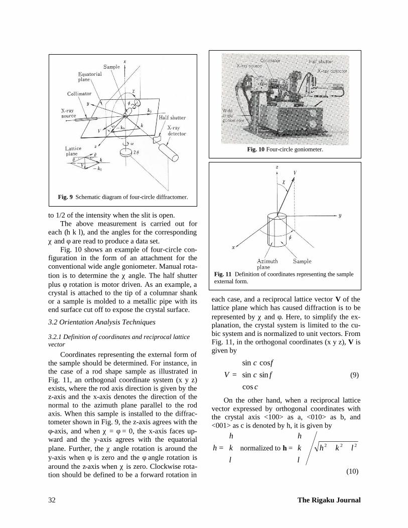
Fig. 10 shows an example of four-circle con-figuration in the form of an attachment for the conventional wide angle goniometer. Manual rota-tion is to determine the χ angle. The half shutter plus φ rotation is motor driven. As an example, a crystal is attached to the tip of a columnar shank or a sample is molded to a metallic pipe with its end surface cut off to expose the crystal surface.
3.2 Orientation Analysis Techniques
3.2.1 Definition of coordinates and reciprocal lattice vector
Coordinates representing the external form of the sample should be determined. For instance, in the case of a rod shape sample as illustrated in Fig. 11, an orthogonal coordinate system (x y z) exists, where the rod axis direction is given by the z-axis and the x-axis denotes the direction of the normal to the azimuth plane parallel to the rod axis. When this sample is installed to the diffrac-tometer shown in Fig. 9, the z-axis agrees with the φ-axis, and when χ = φ = 0, the x-axis faces up-ward and the y-axis agrees with the equatorial plane. Further, the χ angle rotation is around the y-axis when φ is zero and the φ angle rotation is around the z-axis when χ is zero. Clockwise rota-tion should be defined to be a forward rotation in
each case, and a reciprocal lattice vector V of the lattice plane which has caused diffraction is to be represented by χ and φ. Here, to simplify the ex-planation, the crystal system is limited to the cu-bic system and is normalized to unit vectors. From Fig. 11, in the orthogonal coordinates (x y z), V is given by
=
χφχφχ
cossinsincossin
V (9)
On the other hand, when a reciprocal lattice vector expressed by orthogonal coordinates with the crystal axis <100> as a, <010> as b, and <001> as c is denoted by h, it is given by
=
lkh
h normalized to h = 222 lkhlkh
++
(10)
Fig. 9 Schematic diagram of four-circle diffractomer.
Fig. 10 Four-circle goniometer.
Fig. 11 Definition of coordinates representing the sample external form.

Vol. 7. No. 1 1990 33
At this time, indexing of (h k l) corresponding to the measured χ and φ must be done properly by referring to the standard stereo projection chart.
3.2.2 Relations between V and h
The relations between the reciprocal lattice vector V is expressed by the coordinates (x y z). This represents the external shape of the crystal, the reciprocal lattice vector h denoted by the crys-tal axis (abc), and is given by Eq. (11).
V=Uh (11) U is a 3-row, 3-column matrix with a value
inherent to the sample for measurement. Once U is determined, reciprocal vectors corresponding to every (h k l) will be determined to denote orienta- tion. The conversion matrix U for V and h is an orthonormalized matrix referred to as an orienta-tion matrix.
3.2.3 Determination of orientation matrix U
For the determination of U, at least three sets of linearly independent V and h – V1h1, V2h2, and V3h3 – are required.
From Eq. (11), the following holds. V1 = Uh1 V2 = Uh2 (12) V3 = Uh3
By setting
=
3
2
1
|
V
V
V
V , H=
3
2
1
h
h
h
(13)
then Eq. (11) is expressed as |V=UH (14)
Hence U= |VH-1 The three sets of measurement data must not
have a common plane. It is also possible to refine U with a number of data by using the least squares method.
U is not strictly orthonormalized due to meas-urement errors. U must therefore be orthonormal-ized so as to prevent errors in subsequent calcula-tions.
3.3 Orientation Display Method Each component of the orientation matrix U
consists of the direction cosine between the coor-dinate axes x, y and z. This represents the external form of the sample and the crystal axes, a, band c. Although these components themselves indicate
the orientation, what they offer is not intuitive knowledge. As a way of graphically illustrating the crystal orientation, a stereographic projection chart is created. Fig. 12 shows an output example where poles for plotting are limited to {100}, {110} and {110}, and a great circle to denote the crystal zone is drawn for {100} and {110}. In or-der to represent each pole in terms of the numeric value, both the vector components and the orienta-
Vector component Orientation
angle (hkl) x y z α β
(0 1 0) -0.4321 0.8877 0.1592 80.84 115.95 (0 0 1) 0.3905 0.0136 0.9205 23.00 2.00 ( 1 0 0) -0.8138 -0.4698 0.3420 70.00 -150.00 (0 1 1) -0.0263 0.6371 0.7703 39.62 92.37 (1 0 1) 0.8476 0.3403 0.4072 65.97 21.87
( 1 1 0) -0.8873 0.2918 0.3571 69.08 161.80
( 1 0 1) -0.3007 -0.3241 0.8969 26.24 -132.86 ( 1 1 0) -0.2733 -0.9530 0.1305 82.50 -106.00 (0 1 1) 0.5786 -0.6114 0.5398 57.33 -46.58 (1 1 1) 0.4487 0.7862 0.4250 64.85 60.29 ( 1 1 1) -0.4980 0.2469 0.8313 33.77 153.63 ( 1 1 1) 0.0023 -0.7701 0.6379 50.36 -89.83 (1 1 1) 0.9428 -0.2279 0.2433 75.92 -13.59
Fig. 12 Output example of orientation measuring results.
Fig. 13 Laue method (back reflection)

The Rigaku Journal 34
tion angles α and β are illustrated together. The orientation angles α and β are newly calculated from the determined U, and correspond to χ and φ in Fig. 11, respectively.
4. Orientation Determination by the Laue Method
While the diffractometer method uses charac-teristic X-ray, the Laue method uses continuous X-ray incident on a fixed crystal. Accordingly, the X-ray incidence angle with respect to each lattice plane of the crystal is determined by itself. Dif-fraction occurs from a lattice plane when a wave-length satisfies the Bragg condition. Fig. 13 shows the arrangement for the back reflection Laue
method which offers convenience for an orienta-tion measurement. X-rays are directed by the col-limator and are incident on the crystal. Diffracted beams due to lattice planes within the crystal pro-duce diffraction spots on the X-ray film placed perpendicularly to the incident X-rays. These spots are known as Laue spots, which create a Laue pattern.
The direction V of the lattice plane that corre-sponds to the Laue spot can be obtained from the Laue spot coordinates and the film-to-crystal dis-tance. The X-ray wavelength that contributes to diffraction is unknown yet, so the interplanar spacing cannot be determined and therefore the plane indices cannot be identified. For indexing of Laue spots, a general practice is to measure the angles using a chart for analysis, and comparing with the interplanar angular table. This procedure is described in detail in the literature [1]. How-ever, because the work is done manually, the re-sultant precision for orientation determination has so far remained 1 to 2 degrees. But this status has changed recently. Currently, indexing is per-formed by comparing Laue patterns of different types of orientation [11] generated by a computer, followed by the orientation determination through the techniques referred to in 3.2. In another case, Laue spots are input by a digitizer for eventual automatic orientation analysis [12], and so on. Thus time is saved and the precision enhanced to 0.1 to 0.2°.
Moreover, there is another method available that takes advantage of the symmetry of a pattern in the orientation determination by the Laue method. When incident X-rays are directed to a crystal of the cubic system perpendicularly to (100), a 4-times rotation symmetric pattern is ex-hibited; likewise, 3-times and 2-times rotation symmetric patterns are exhibited with (111) and (110), respectively. Fig. 14 illustrates the Laue pattern of a TiC single crystal photographed with a high-sensitivity TV camera using mirror reflec-tion by arranging a fluorescent screen in place of the X-ray film. (a): Before the orientation adjust-ment. Chains of spots intersect each other cross-wise. The cross point is presumed to be spot (100). (b): A 4-time rotation symmetric pattern obtained by rotational operation to move this cross point to the center on the screen'
(a) before the orientation adjustment
(b) after adjustment
Fig. 14 Videodisplay of Laue pattern.

Vol. 7. No. 1 1990 35
5. Concluding Remarks Outlined above are the diffractometer method
and the Laue method that are often used in the orientation measurement of single crystals utiliz-ing X-ray diffraction. Hopefully, this paper may serve as reference for those engaged in the field work related to crystals.
(Note) This paper appeared in 'CERAMICS' 23 (1988) No.2. Bibliography
[1] B, D. Cullity: "Elements of X-ray Diffraction", Addison- Wesley (1980).
[2] R. A. Heising: "Quartz Crystal for Electrical Circuit", Chapter III, D. Van Norstrand Co., Inc., New York (1946).
[3] Rigaku Corporation: Japanese patent, Sho 57 ('82)- 136150.
[4] JIS: Artificial Quartz C6704-1981 .
[5] M. Fujita and N. Asanuma: Toyo Tsushinki Technical Bulletin.
[6] Y. Kobayashi: "Proceedings of the 32nd Annual Sympo-sium on Frequency Control”, U.S. Army Electronics Re-search and Development Command (1978) pp. 317-20.
[7] W, L. Bond: "Proceedings of the I.R.E." (1950) pp. 886-89.
[8] Japan Electronic Industry Development Association: Measurement Method for Crystal Orientation of Silicon Crystal, J EDA-18-1 973.
[9] T. Abe, M. Odagiri and K. Taniguchi: "Silicon Crystal and Doping", Maruzen (1986) p. 21.
[10] W. C. Hamilton: "International Tables for X-ray Crystal-lography Vol. IV", Kynoch Press, Birmingham (1974) pp. 273-284.
[11] E. Preuss, B. Krahl-Urbana and B. Butz: "Laue Atlas", Wiley, New York (1974).
[12] O. Ito and B. Hashimoto: Materials, 34, 11 05-09 (1985). ,