
THE REMEHA HIU RANGE · INTRODUCING THE HEAT INTERFACE UNIT RANGE The Remeha Heat Interface Unit...
24
THE REMEHA HIU RANGE
Transcript of THE REMEHA HIU RANGE · INTRODUCING THE HEAT INTERFACE UNIT RANGE The Remeha Heat Interface Unit...
THE REMEHA HIU RANGE

WHAT’S INSIDE
03 WELCOME TO REMEHA
03 INTRODUCING THE HIU RANGE
04 TECHNICAL INFORMATION
07 ENGINEERING SPECIFICATION
08 HIU CONSTRUCTION
10 SPECIFICATIONS
14 HYDRAULIC SCHEMATIC
16 WIRING DIAGRAM
17 COMPONENTS AND RECOMMENDED AND ADDITIONAL OPTIONS
19 TECHNICAL CALCULATION GUIDE
20 DIVERSITY FACTOR
21 FLOW RATE CALCULATION
23 TECHNICAL SUPPORT
23 DECLARATION OF COMPLIANCE
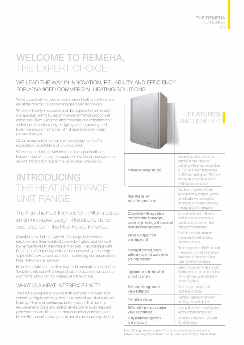
INTRODUCING THE HEAT INTERFACE UNIT RANGE The Remeha Heat Interface Unit (HIU) is based on an innovative design, intended to deliver best practice in the Heat Network market.
Available as an indirect twin HIU, the range incorporates electronic and thermostatically controlled valves and works at
Remeha’s offering of low carbon and condensing technologies to provide a low carbon plant room, optimising the opportunities Heat Networks can provide.
WHAT IS A HEAT INTERFACE UNIT? The HIU is designed to provide both domestic hot water and central heating to dwellings which are served by either a district heating scheme or centralised boiler system. This helps to reduce energy costs and carbon emissions through reduced gas consumption. Due to the smaller number of moving parts
Innovative design of unit
Future-proofed to deliver best practice in heat networks
of 70o
of 40oC for heating and 70o
oC for hot water production
Operates at low return temperatures
Distribution pipework losses
centralised low or zero carbon
Compatible with low carbon energy centres for example, condensing heating and Combined Heat and Power products
Variable output from one single unit
of a range of dwelling sizes
Intelligent internal control with domestic hot water plate pre-heat function
lower potential fuel usage
Jig/frame can be installed Ease of installation – testing and
HIU is delivered and installed at
Self-modulating control valve actuators
Twin plate designdwelling and central plant
Differential pressure control valve as standard
Fully insulated pipework and enclosure standard losses
03
THE REMEHA HIU RANGE
Note: Although we recommend the best practice industry standards on network operating temperatures, our HIUs also work at higher temperatures.
WELCOME TO REMEHA, THE EXPERT CHOICEWE LEAD THE WAY IN INNOVATION, RELIABILITY AND EFFICIENCY
We’re completely focused on commercial heating solutions and are at the forefront of condensing gas boiler technology.
We invest heavily in research and development which enables our specialist teams to design high-performance products at every level. From using the latest materials and manufacturing techniques to meticulously designing and engineering each boiler, we ensure they’re the right choice to specify, install, run and maintain.
All our boilers share the same simple design, so they’re expandable, adaptable and future-proofed.
blueprint sign off through to supply and installation, our customer service and product support is our number one priority.
FEATURES AND BENEFITS
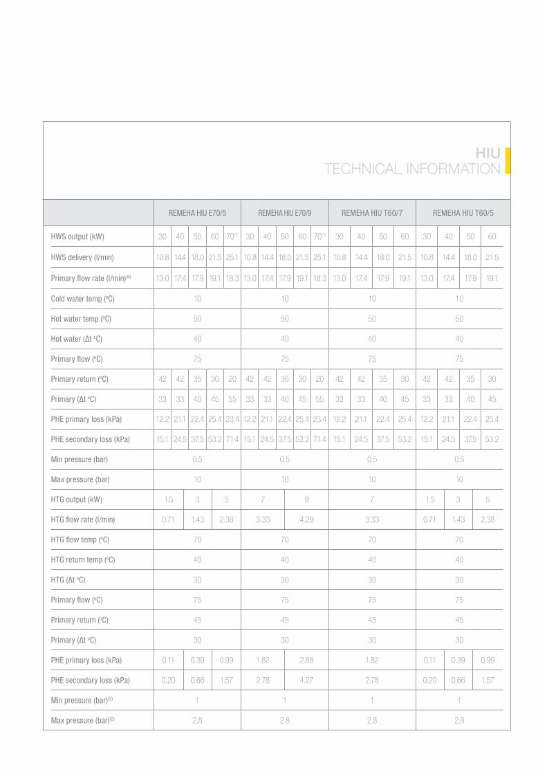
REMEHA HIU E70/5 REMEHA HIU E70/9 REMEHA HIU T60/7 REMEHA HIU T60/5
HWS output (kW) 30 40 60 70(1) 30 40 60 70(1) 30 40 60 30 40 60
HWS delivery (l/min)
(6)
Cold water temp (oC) 10 10 10 10
Hot water temp (oC)
oC) 40 40 40 40
oC)
Primary return (oC) 30 30 30 30
oC) 33 33 40 33 33 40 33 33 40 33 33 40
PHE primary loss (kPa)
PHE secondary loss (kPa)
Min pressure (bar)
Max pressure (bar) 10 10 10 10
HTG output (kW) 3 7 7 3
oC) 70 70 70 70
HTG return temp (oC) 40 40 40 40
oC) 30 30 30 30
oC)
Primary return (oC)
oC) 30 30 30 30
PHE primary loss (kPa)
PHE secondary loss (kPa)
Min pressure (bar)(3) 1 1 1 1
Max pressure (bar)(2)
HIU TECHNICAL INFORMATION
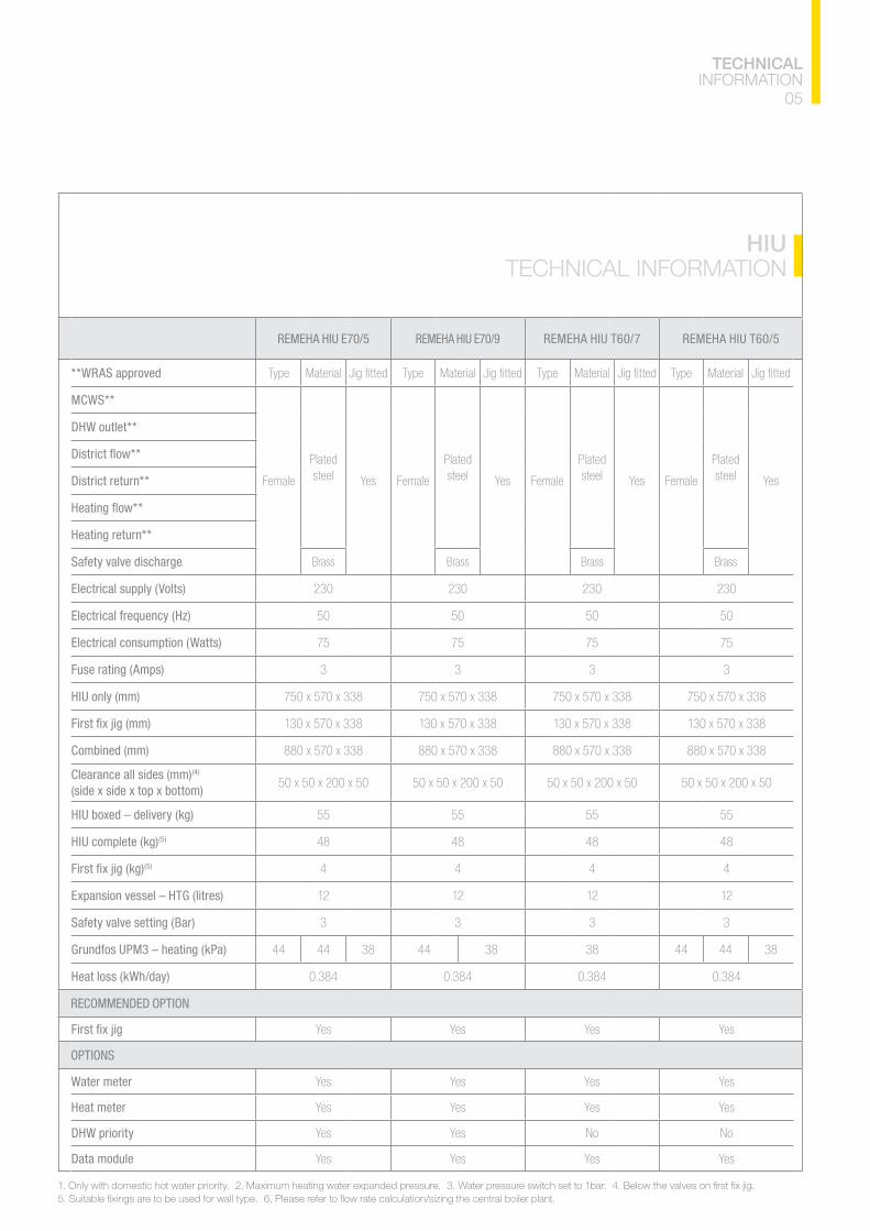
REMEHA HIU E70/5 REMEHA HIU E70/9 REMEHA HIU T60/7 REMEHA HIU T60/5
**WRAS approved Material Material Material Material
MCWS**
Plated steel Yes
Plated steel Yes
Plated steel Yes
Plated steel Yes
DHW outlet**
District return**
Heating return**
Safety valve discharge Brass Brass Brass Brass
Electrical supply (Volts)
Electrical frequency (Hz)
Electrical consumption (Watts)
Fuse rating (Amps) 3 3 3 3
HIU only (mm)
Combined (mm)
Clearance all sides (mm)(4) (side x side x top x bottom)
HIU boxed – delivery (kg)
HIU complete (kg)(5)
(5) 4 4 4 4
Expansion vessel – HTG (litres)
Safety valve setting (Bar) 3 3 3 3
Grundfos UPM3 – heating (kPa) 44 44 44 44 44
Heat loss (kWh/day)
RECOMMENDED OPTION
Yes Yes Yes Yes
OPTIONS
Water meter Yes Yes Yes Yes
Heat meter Yes Yes Yes Yes
DHW priority Yes Yes No No
Data module Yes Yes Yes Yes
HIU TECHNICAL INFORMATION
05
TECHNICAL INFORMATION
07
SUGGESTED ENGINEERING SPECIFICATION
SUGGESTED ENGINEERING SPECIFICATION
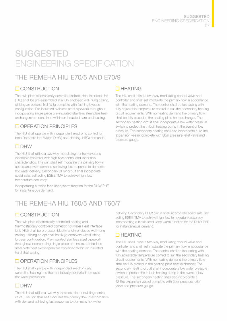
THE REMEHA HIU E70/5 AND E70/9
CONSTRUCTIONThe twin plate electronically controlled indirect Heat Interface Unit (HIU) shall be pre-assembled in a fully enclosed wall-hung casing,
incorporating single piece pre-insulated stainless steel plate heat exchangers are contained within an insulated hard shell casing.
OPERATION PRINCIPLES The HIU shall operate with independent electronic control for both Domestic Hot Water (DHW) and Heating (HTG) demands.
DHWThe HIU shall utilise a two-way modulating control valve and
accordance with demand achieving fast response to domestic hot water delivery. Secondary DHW circuit shall incorporate
temperature accuracy.
for instantaneous demand.
HEATING The HIU shall utilise a two-way modulating control valve and
with the heating demand. The control shall be fast acting with fully adjustable temperature control to suit the secondary heating
shall be fully closed to the heating plate heat exchanger. The secondary heating circuit shall incorporate a low water pressure switch to protect the in-built heating pump in the event of low pressure. The secondary heating shall also incorporate a 12 litre expansion vessel complete with 3bar pressure relief valve and pressure gauge.
THE REMEHA HIU T60/5 AND T60/7
CONSTRUCTIONThe twin plate electronically controlled heating and thermostatically controlled domestic hot water Heat Interface Unit (HIU) shall be pre-assembled in a fully enclosed wall-hung
throughout incorporating single piece pre-insulated stainless steel plate heat exchangers are contained within an insulated hard shell casing.
OPERATION PRINCIPLES The HIU shall operate with independent electronically controlled heating and thermostatically controlled domestic hot water production.
DHWThe HIU shall utilise a two-way thermostatic modulating control
with demand achieving fast response to domestic hot water
delivery. Secondary DHW circuit shall incorporate scald safe, self
for instantaneous demand.
HEATING The HIU shall utilise a two-way modulating control valve and
with the heating demand. The control shall be fast acting with fully adjustable temperature control to suit the secondary heating
shall be fully closed to the heating plate heat exchanger. The secondary heating circuit shall incorporate a low water pressure switch to protect the in-built heating pump in the event of low pressure. The secondary heating shall also incorporate a 12 litre expansion vessel complete with 3bar pressure relief valve and pressure gauge.
KEY
1 7 13
14
3 Pressure switch
4 10 16
11 17
6 Differential pressure controller Check value (non-return valve)
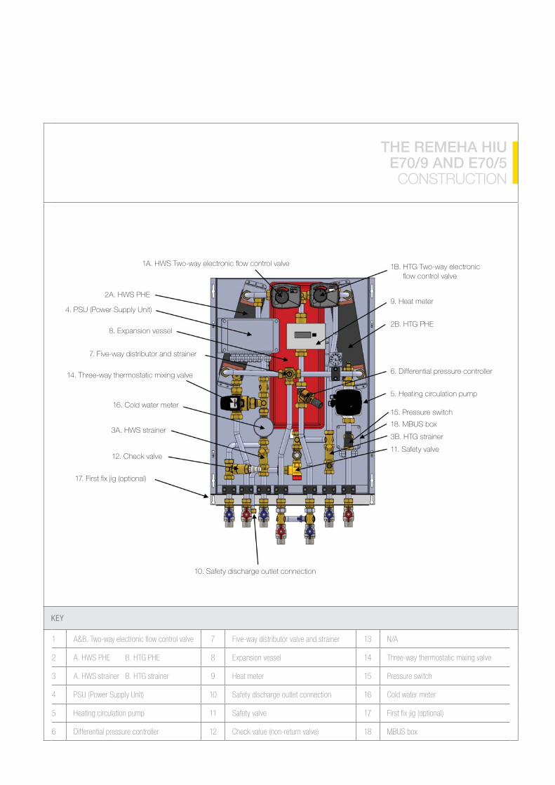
THE REMEHA HIU E70/9 AND E70/5 CONSTRUCTION
8. Expansion vessel
7. Five-way distributor and strainer
14. Three-way thermostatic mixing valve
3A. HWS strainer
1B. HTG Two-way electronic
9. Heat meter
5. Heating circulation pump
18. MBUS box
3B. HTG strainer
11. Safety valve
10. Safety discharge outlet connection
09
THE REMEHA HIU CONSTRUCTION
KEY
1 7 13
14
3 Pressure switch
4 10 16
11 17
6 Differential pressure controller Check value (non-return valve)
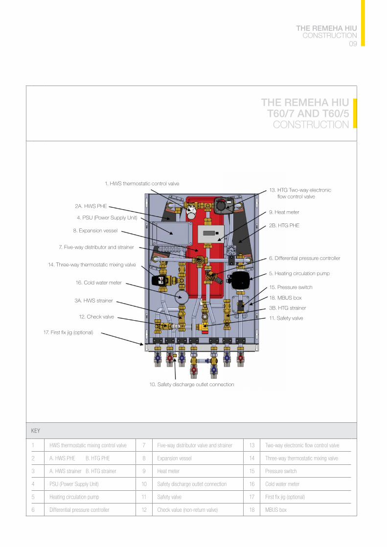
THE REMEHA HIU T60/7 AND T60/5 CONSTRUCTION
1. HWS thermostatic control valve
8. Expansion vessel
7. Five-way distributor and strainer
14. Three-way thermostatic mixing valve
3A. HWS strainer
10. Safety discharge outlet connection
13. HTG Two-way electronic
9. Heat meter
5. Heating circulation pump
18. MBUS box
3B. HTG strainer
11. Safety valve
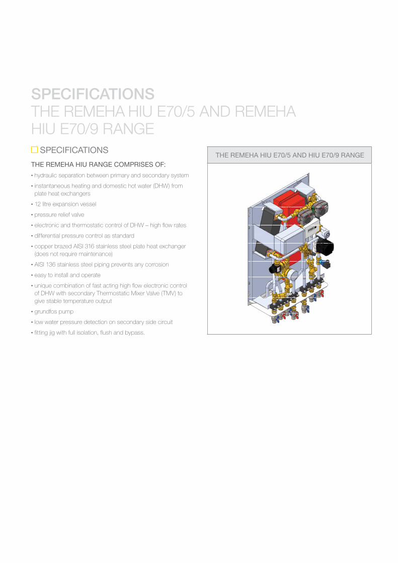
SPECIFICATIONS THE REMEHA HIU E70/5 AND REMEHA HIU E70/9 RANGE
SPECIFICATIONS
THE REMEHA HIU RANGE COMPRISES OF:• hydraulic separation between primary and secondary system
• instantaneous heating and domestic hot water (DHW) from plate heat exchangers
• 12 litre expansion vessel
• pressure relief valve
•
• differential pressure control as standard
•
(does not require maintenance)
•
• easy to install and operate
• of DHW with secondary Thermostatic Mixer Valve (TMV) to give stable temperature output
• grundfos pump
• low water pressure detection on secondary side circuit
•
THE REMEHA HIU E70/5 AND HIU E70/9 RANGE

11SPECIFICATIONS
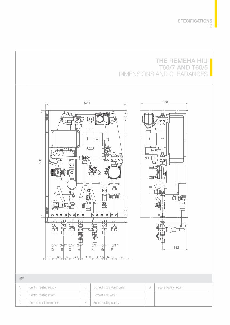
KEY
D
B Central heating return E
C F
THE REMEHA HIU E70/5 AND E70/9
DIMENSIONS AND CLEARANCES
570
750
65 60 60 60 100 67,5 67,5 90
182
338
3/4'' 3/4'' 3/4'' 3/4''''4/3 ''4/3 ''4/3D E C A B G F
SPECIFICATIONS
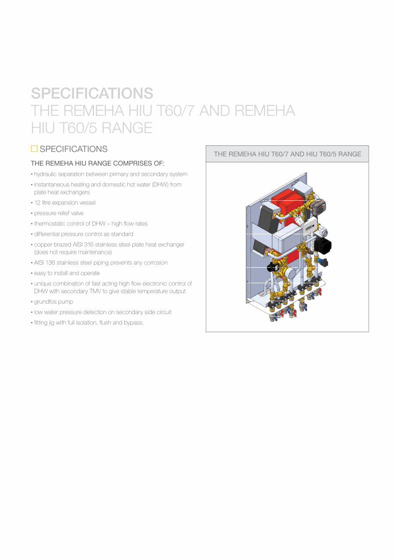
THE REMEHA HIU T60/7 AND REMEHA HIU T60/5 RANGE
SPECIFICATIONS
THE REMEHA HIU RANGE COMPRISES OF:• hydraulic separation between primary and secondary system
• instantaneous heating and domestic hot water (DHW) from plate heat exchangers
• 12 litre expansion vessel
• pressure relief valve
•
• differential pressure control as standard
•
(does not require maintenance)
•
• easy to install and operate
•
DHW with secondary TMV to give stable temperature output
• grundfos pump
• low water pressure detection on secondary side circuit
•
THE REMEHA HIU T60/7 AND HIU T60/5 RANGE
13SPECIFICATIONS
KEY
D
B Central heating return E
C F
THE REMEHA HIU T60/7 AND T60/5
DIMENSIONS AND CLEARANCES
570
750
65 60 60 60 100 67,5 67,5 90
182
338
3/4'' 3/4'' 3/4'' 3/4''''4/3 ''4/3 ''4/3D E C A B G F
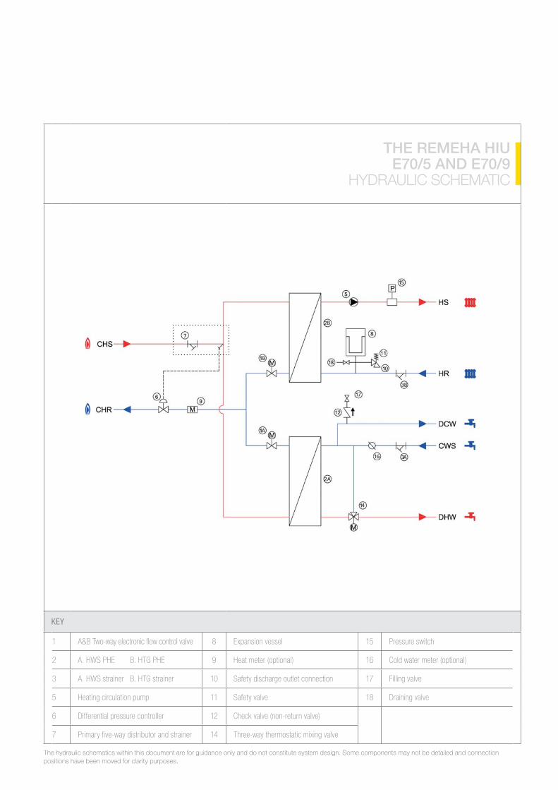
KEY
1 Pressure switch
16
3 10 17 Filling valve
11 Draining valve
6 Differential pressure controller Check valve (non-return valve)
7 14
THE REMEHA HIU E70/5 AND E70/9
HYDRAULIC SCHEMATIC
The hydraulic schematics within this document are for guidance only and do not constitute system design. Some components may not be detailed and connection positions have been moved for clarity purposes.
15
HYDRAULIC SCHEMATIC
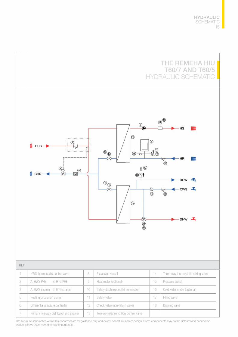
KEY
1 14
Pressure switch
3 10 16
11 17 Filling valve
6 Differential pressure controller Check valve (non-return valve) Draining valve
7 13
THE REMEHA HIU T60/7 AND T60/5
HYDRAULIC SCHEMATIC
The hydraulic schematics within this document are for guidance only and do not constitute system design. Some components may not be detailed and connection positions have been moved for clarity purposes.
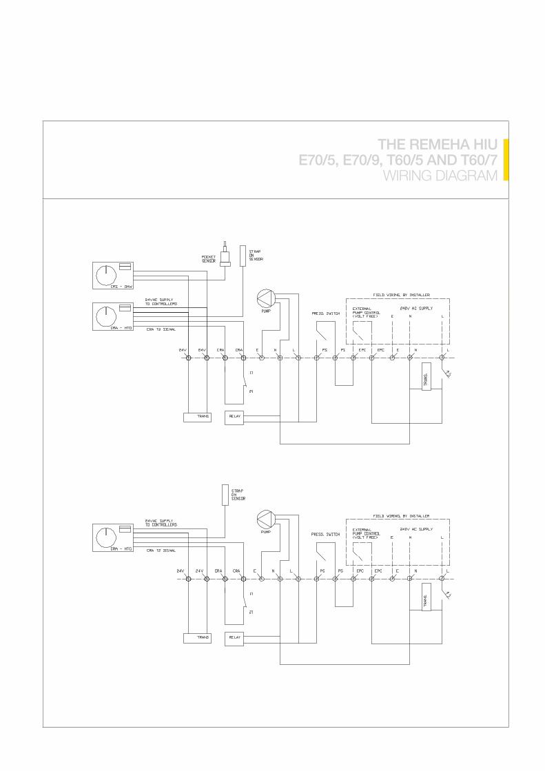
THE REMEHA HIU E70/5, E70/9, T60/5 AND T60/7
WIRING DIAGRAM
17
THE REMEHA HIU WIRING DIAGRAM, COMPONENTS AND
RECOMMENDED AND ADDITIONAL OPTIONS
THE REMEHA HIU COMPONENTS
ELECTRICAL CONNECTIONS The electrical connections comprise of:
• heating on/off
• safety interlock.
RECOMMENDED OPTIONS FIRST FIX JIG
bypass which allows for:
• pipe work installation prior to HIU mounting
•
ADDITIONAL OPTIONS HEAT METER
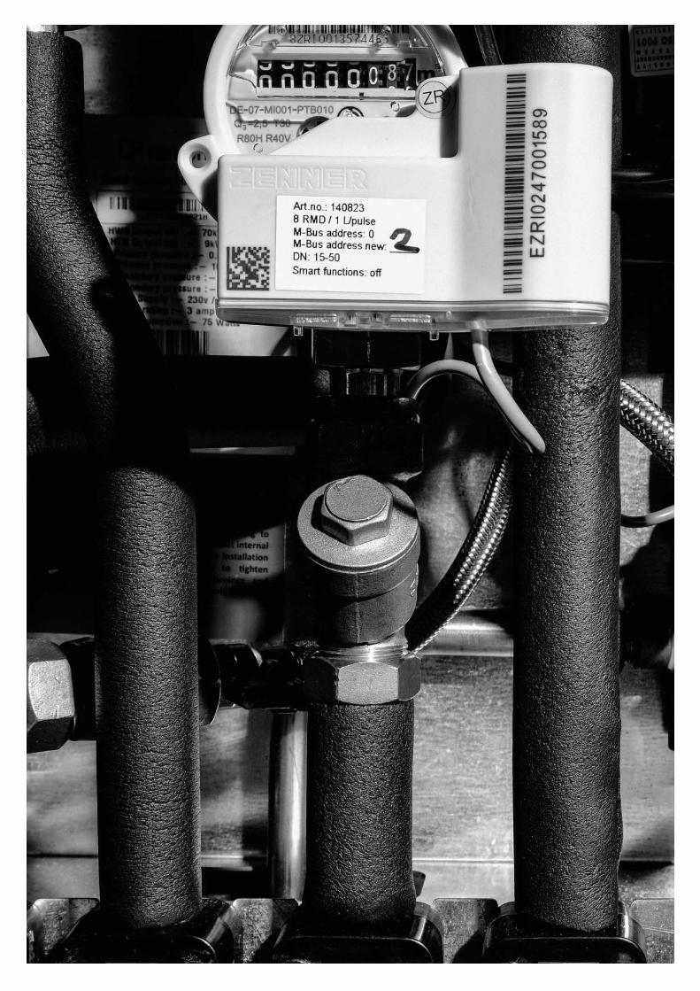
Heat meters are used to measure the distribution of heat energy within the dwelling by calculating the volume and temperature differential of circulated water. It has MBUS feedback allowing for the remote recording of energy usage for billing purposes.
WATER METER MBUSRemeha offer a water meter MBUS as an optional extra for volumetric water consumption.
DOMESTIC HOT WATER PRIORITYThe Remeha E series HIU range offers a domestic hot water priority feature as an optional extra. This provides the advantage of full primary input diversion for DHW production providing
without priority domestic hot water option).


OUTPUT RATING (kW)
PRIMARY DELTA (T) (oC)
SECONDARY DELTA (T) (oC)
PRIMARY PLATE
PRESSURE DROP (kPa)
SECONDARY PLATE
PRESSURE DROP (kPa)
PRIMARY FLOW RATE
(l/m)
SECONDARY FLOW RATE
(l/m)
PRIMARY CONTROL Vv PRESSURE DROP (kPa)
TOTAL PRIMARY
PRESSURE DROP (kPa)
3
7
TECHNICAL CALCULATION GUIDE
DHW CALCULATIONS
HEATING CALCULATIONS
19
TECHNICAL CALCULATION GUIDE
OUTPUT RATING (kW)
PRIMARY DELTA (T) (oC)
SECONDARY DELTA (T) (oC)
PRIMARY PLATE
PRESSURE DROP (kPa)
SECONDARY PLATE
PRESSURE DROP (kPa)
PRIMARY FLOW RATE
(l/m)
SECONDARY FLOW RATE
(l/m)
PRIMARY CONTROL Vv PRESSURE DROP (kPa)
TOTAL PRIMARY
PRESSURE DROP (kPa)
30
40
60
70

NUMBER OF HIU(S)
DIVERSITY
1 1
3
4
6
7
10
11
13
14
16
17
30
31
33
NUMBER OF HIU(S)
DIVERSITY
34
36
37
40
41
43
44
46
47
60
61
63
64
66
NUMBER OF HIU(S)
DIVERSITY
67
70
71
73
74
76
77
DIVERSITY FACTOR
TYPICAL DIVERSITY FACTOR
21
DIVERSITY FACTOR AND FLOW RATE CALCULATION
FLOW RATE CALCULATION SIZING THE CENTRAL BOILER PLANT
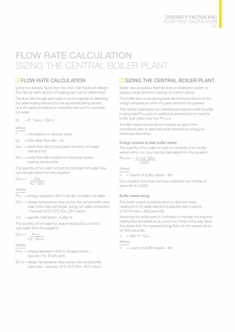
FLOW RATE CALCULATIONUsing the diversity factor from the chart, the maximum design
the peak heating demand for the apartment being served
hot water.
QT HW) + (QHTG)
Where
QT
QHW demand (l/s)
QHTG heating demand (l/s)
The quantity of hot water to heat the domestic hot water QHW can be calculated from the equation:
QDHW HW DH
Where
HW
DH
side of the heat exchanger during hot water production – typically 50o o o
oK
The quantity of hot water for space heating QHTG can be calculated from the equation:
QHTG HTG HTG
Where
HTG typically 3 to 10 kW each.
HTG plant side – typically 30o o o
SIZING THE CENTRAL BOILER PLANTBuffer tank provides a thermal store to enable the system to supply a large amount of energy for a short period.
The buffer tank cools during peak demand and returns to the design temperature when the peak demand has passed.
HTG plus an additional allowance to re-heat the BUFFER.
A buffer vessel should still be installed as part of the centralised plant to deal with peak demand for energy as previously described.
The quantity of hot water to heat the contents of the buffer vessel within one hour can be calculated from the equation:
BUFFER DH
Where
For a duration less than one hour substitute the number of seconds for 3,500.
heating and hot water demand sustained over a period
Assuming the boiler plant is controlled to maintain the required
for 900 seconds.
QHW
Where


23
TECHNICAL SUPPORT AND DECLARATION OF COMPLIANCE
TECHNICAL SUPPORT
need at remeha.co.uk
Or call our sales or technical departments on 0118 978 3434. We’re always happy to help.
We can provide you with:
• Brochures
•
•
• Installation manuals
•
•
• Energy-related products directive data
•
• Technical information
• Spare parts (after sales).
DECLARATION OF COMPLIANCE
declaration of compliance, and that it is manufactured and marketed in compliance with the requirements and standards of the following European Directives.
The installation must be carried out by a competent plumbing and electrical installer in accordance with Building Regulations, The Building Standards (Scotland) Regulations 1990, The Building Regulations (Northern Ireland), UK Water Regulations and IEE Electrical Regulations.
Also, BSEN.12828:2003 – Heating Systems in buildings Design for water based systems.
BSEN.12831:2003 Heating Systems in buildings: Method for calculation of the design heat load.
diaphragm, for sealed hot water heating systems.
commissioning of water based heating systems.
The appropriate Building Regulations either The Building Regulations, The Building Regulations (Scotland), Building Regulations (Northern Ireland).
The Water Fittings Regulations or Water Bye laws in Scotland.
Low Voltage Directive 2014/35/EU.

T E W