The Reliability Investigation on ACSR Splice Connector ...
6
European Association for the Development of Renewable Energies, Environment and Power Quality (EA4EPQ) International Conference on Renewable Energies and Power Quality (ICREPQ’12) Santiago de Compostela (Spain), 28th to 30th March, 2012 The Reliability Investigation on ACSR Splice Connector Systems Used in Overhead Power Transmission Lines Jy-An John Wang*, Hao Jiang, Fei Ren Oak Ridge National Laboratory 1 Bethel Valley Road Oak Ridge, TN 37830 USA * Phone/Fax number: +001 865-574-2274, e-mail: [email protected] Abstract Due to material discontinuity and inherited forming mechanism from a crimped-type splice connector, the associated conductor-connector system is highly sensitive to system components aging, especially during high-temperature operations. Furthermore, due to the increase in power demand and limited investment in new infrastructure, existing overhead power transmission lines often need to operate at temperatures higher than the original designed values. This has led to the accelerated aging and degradation of conductor-connector systems. The implications of connector aging are two-fold: (1) significant increase in resistivity of the splice connector and (2) significant reduction in the connector clamping strength. Therefore, splice connectors are one of the weakest links in the electric power transmission infrastructure. In this paper we will discuss the reliability of splice connector systems, including both single stage and two stage splice connectors, used in ACSR conductor of transmission lines under high temperature operations. Key words ACSR, Single-stage splice connector, Two-stage splice connector, Power transmission lines, compressive fitting 1. Introduction The majority of overhead transmission lines currently in use are steel-reinforced core aluminium conductors (ACSR). The crimped-type splice connectors are widely used in the power industry, including the single-stage splice connectors (SSC) and the two-stage splice connectors (TSC). As a result of increasing power demands and the higher operating temperatures of transmission lines, the integrity of crimped-type splice connectors is one major concern that plays an important role in the efficiency and reliability of power transmission system. The objective of this research is to develop a methodology for evaluating the long-term reliability of ACSR splice connector systems for both single stage and two stage splice fittings. The implementation of the methodology allows electrical utility companies to predict the service lifetime of ACSR conductor systems as related to the number of thermal cycles associated with operation during peak periods. The time-dependent failure criteria are established to assure adequate service life of ACSR SSC and TSC systems and thus to significantly improve the transmission capacity of the electric grid and its reliability. Previously developed methodology to evaluate SSC systems [1, 2], is extended to the study of TSC systems. The potential of failure frequency of TSC fittings at higher temperature operations is considerably lower than that of SSC fittings. The main reason for the decreased durability of a SSC compared to that of a TSC is due to the material mismatch effect between steel and aluminium within a SSC system. In an SSC an aluminium core-grip is used for clamping and connecting the steel cores, whereas a steel fitting sleeve is used to connect the steel cores for TSC. The compressive residual stress remained in a crimped- type splice connector provides the clamping strength to confine aluminium conductors in a connector system. It is expected that this initial residual stress will relax significantly during service, especially at higher operating temperatures. The relaxation of the initial compressive stress field results in the reduction of the connector’s initial rated tensile breaking strength (RBS) that can be evaluated according to ANSI C119.4 [3]. Fig.1. Schematic diagram showing splice connector interfaces Fig. 1 shows a detailed cross-section view to illustrate the material interfaces between the splice sleeve and the conductors, and between the steel cores and the conductors. It is expected that the gap density at these interfaces will increase as a result of thermal cycling. The consequence of reduced residual stress and the gap formation at these interfaces on the integrity and https://doi.org/10.24084/repqj10.865 1886 RE&PQJ, Vol.1, No.10, April 2012
Transcript of The Reliability Investigation on ACSR Splice Connector ...
European Association for the Development of Renewable Energies, Environment
and Power Quality (EA4EPQ)
International Conference on Renewable Energies and Power Quality (ICREPQ’12)
Santiago de Compostela (Spain), 28th to 30th March, 2012
The Reliability Investigation on ACSR Splice Connector Systems Used in Overhead Power Transmission Lines
Jy-An John Wang*, Hao Jiang, Fei Ren
Oak Ridge National Laboratory 1 Bethel Valley Road
Oak Ridge, TN 37830 USA * Phone/Fax number: +001 865-574-2274, e-mail: [email protected]
Abstract Due to material discontinuity and inherited forming mechanism from a crimped-type splice connector, the associated conductor-connector system is highly sensitive to system components aging, especially during high-temperature operations. Furthermore, due to the increase in power demand and limited investment in new infrastructure, existing overhead power transmission lines often need to operate at temperatures higher than the original designed values. This has led to the accelerated aging and degradation of conductor-connector systems. The implications of connector aging are two-fold: (1) significant increase in resistivity of the splice connector and (2) significant reduction in the connector clamping strength. Therefore, splice connectors are one of the weakest links in the electric power transmission infrastructure. In this paper we will discuss the reliability of splice connector systems, including both single stage and two stage splice connectors, used in ACSR conductor of transmission lines under high temperature operations. Key words ACSR, Single-stage splice connector, Two-stage splice connector, Power transmission lines, compressive fitting 1. Introduction The majority of overhead transmission lines currently in use are steel-reinforced core aluminium conductors (ACSR). The crimped-type splice connectors are widely used in the power industry, including the single-stage splice connectors (SSC) and the two-stage splice connectors (TSC). As a result of increasing power demands and the higher operating temperatures of transmission lines, the integrity of crimped-type splice connectors is one major concern that plays an important role in the efficiency and reliability of power transmission system.
The objective of this research is to develop a methodology for evaluating the long-term reliability of ACSR splice connector systems for both single stage and two stage splice fittings. The implementation of the methodology allows electrical utility companies to predict the service lifetime of ACSR conductor systems as related to the number of thermal cycles associated with operation during peak periods. The time-dependent failure criteria are established to assure adequate service life of ACSR SSC
and TSC systems and thus to significantly improve the transmission capacity of the electric grid and its reliability. Previously developed methodology to evaluate SSC systems [1, 2], is extended to the study of TSC systems. The potential of failure frequency of TSC fittings at higher temperature operations is considerably lower than that of SSC fittings. The main reason for the decreased durability of a SSC compared to that of a TSC is due to the material mismatch effect between steel and aluminium within a SSC system. In an SSC an aluminium core-grip is used for clamping and connecting the steel cores, whereas a steel fitting sleeve is used to connect the steel cores for TSC. The compressive residual stress remained in a crimped-type splice connector provides the clamping strength to confine aluminium conductors in a connector system. It is expected that this initial residual stress will relax significantly during service, especially at higher operating temperatures. The relaxation of the initial compressive stress field results in the reduction of the connector’s initial rated tensile breaking strength (RBS) that can be evaluated according to ANSI C119.4 [3].
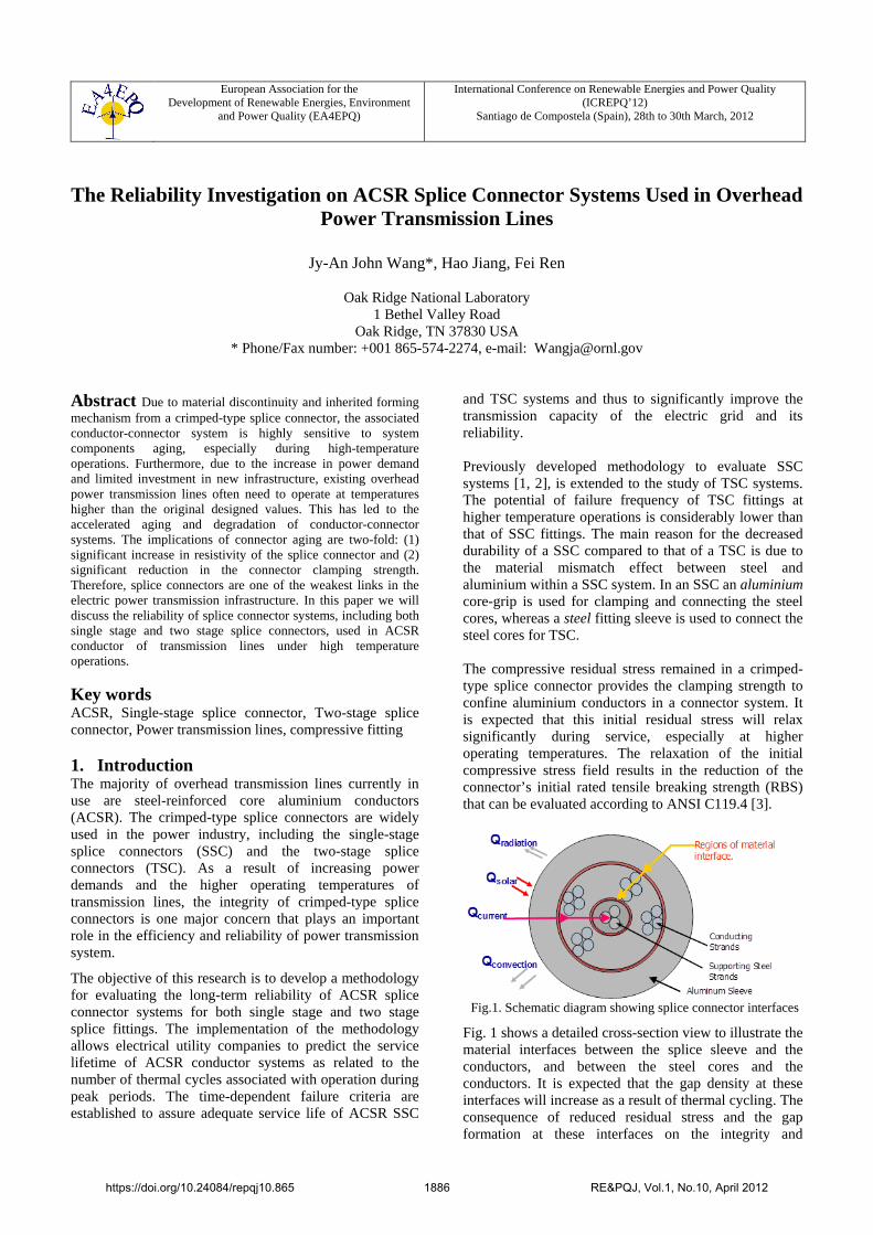
Fig.1. Schematic diagram showing splice connector interfaces
Fig. 1 shows a detailed cross-section view to illustrate the material interfaces between the splice sleeve and the conductors, and between the steel cores and the conductors. It is expected that the gap density at these interfaces will increase as a result of thermal cycling. The consequence of reduced residual stress and the gap formation at these interfaces on the integrity and
https://doi.org/10.24084/repqj10.865 1886 RE&PQJ, Vol.1, No.10, April 2012
reliability of ACSR SSC and TSC systems is reduced electrical and thermal conductivities, which could lead to higher local temperatures, accelerated aging, and relaxation of the clamping stress. Thus the compressive residual stress in the splice connector is the key parameter for predicting the effective lifetime of ACSR systems during service. 2. Temperature Profiles and Thermo-
Mechanical Characterization In collaboration with the Electrical Power Research Institute (EPRI) a series of experiments were carried out to determine the temperature profiles within the connector fitting of an ACSR Drake conductor system during thermal cycling. Measurements were obtained for conductors with both SSC and TSC connectors [1].
These experiments revealed that [1]: 1) For a new system, the connector surface temperature
is lower than the power line surface temperature. 2) The temperature at the steel core is normally higher
than that of the aluminium wires, except at the core-grip region.
3) The temperatures of the connector system increase continuously during thermal cycling; temperature gradients observed from the embedded thermocouples (TCs) in the connector also change with thermal cycling.
4) Significant temperature increases are due to increased fitting resistivity. This is a direct result of the thermal cycle induced reduction in compressive residual stresses in the fitting.
The thermomechanical tests included tensile, creep, fatigue tests and thermomechanical fatigue. These tests were carried out for aluminum alloys 1350-H19 (conductor), 3003-H183 (SSC sleeve) and 6061-T6 (SSC core-grip). Pertinent test information and results are summarized below:
1) Significant decrease in strength was observed at high temperatures. For instance, at 260°C, the strength reductions are
a. 1350-H19: 77%; b. 3003-H183: 67% c. 6061-T6: 45%; with 10 hour holding: 60%.
2) In order to simulate two thermal cycles per day (typical service conditions for power lines), the holding time for the tensile samples at the target temperature was set to 10 hours.
3) Thermal annealing had significant impact on the SSC component strength, as revealed from the decrease in tensile strength of annealed samples at room temperature, especially for annealing temperature greater than 200°C.
4) The true stress-true plastic strain curves were generated through thermal mechanical testing for 1350-H19, 3003-H183 and 6061-T6 aluminum materials, to provide inelastic mechanical properties input for the finite element modeling (FEM).
5) Inelastic stress-strain curves for the 1100-H12 aluminum material (TSC sleeve) at elevated
temperature were also generated to serve as input for FEM thermal cycling analyses. Annealing of work-hardened aluminum alloys (especially above 200°C) could result in changes in their mechanical properties. The annealed data, 1100-H12 aluminum alloy after being annealed for 10 hours at 205°C, 230°C, 260°C, and 315°C, respectively, showed a significant decrease in true stress-strain curves compared to that of baseline data.
3. Finite Element Analysis of ACSR SSC and TSC System
An ACSR Drake conductor, consisting of 26 aluminum conductor wires and seven core steel wires, the ALCOA aluminum splice sleeve and the core-grip, and the associated AFL 60 tons 6012CD die set for SSC fitting and AFL 60 tons die set (6030AH for aluminum splice and 6014SH for steel core-grip) for TSC fitting were used in FEM to simulate the splice connector forming process and to determine the compressive residual stress fields.
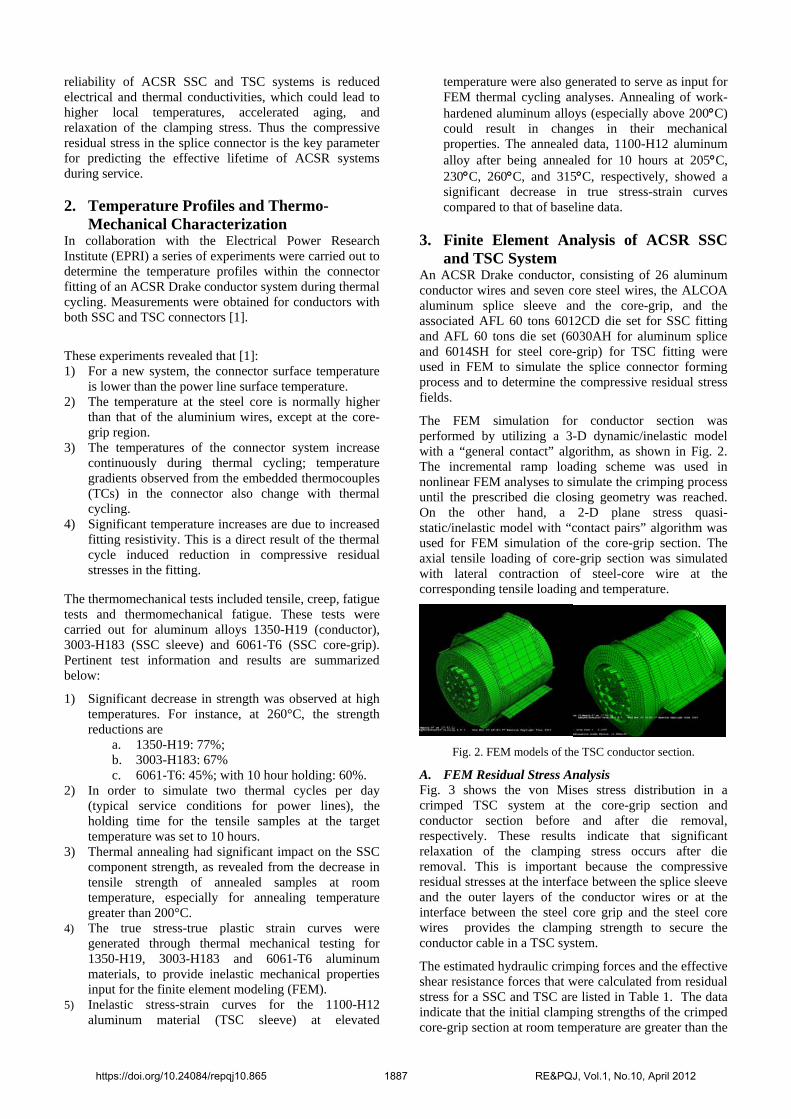
The FEM simulation for conductor section was performed by utilizing a 3-D dynamic/inelastic model with a “general contact” algorithm, as shown in Fig. 2. The incremental ramp loading scheme was used in nonlinear FEM analyses to simulate the crimping process until the prescribed die closing geometry was reached. On the other hand, a 2-D plane stress quasi-static/inelastic model with “contact pairs” algorithm was used for FEM simulation of the core-grip section. The axial tensile loading of core-grip section was simulated with lateral contraction of steel-core wire at the corresponding tensile loading and temperature.
Fig. 2. FEM models of the TSC conductor section.
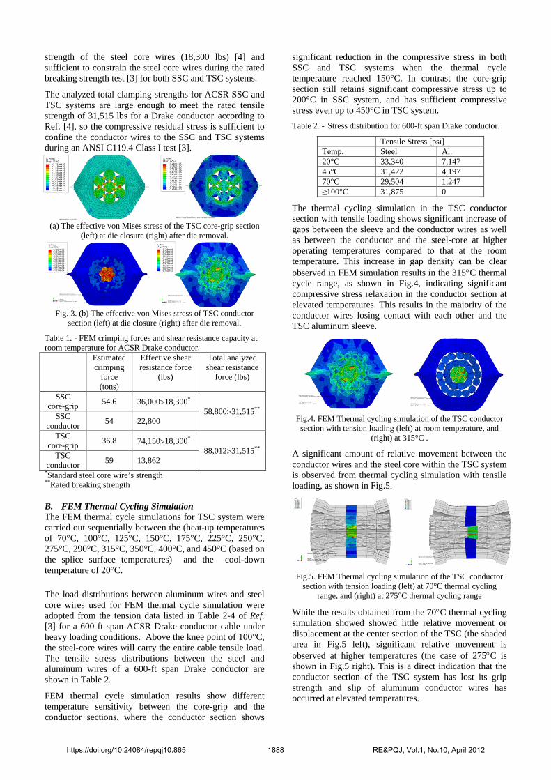
A. FEM Residual Stress Analysis Fig. 3 shows the von Mises stress distribution in a crimped TSC system at the core-grip section and conductor section before and after die removal, respectively. These results indicate that significant relaxation of the clamping stress occurs after die removal. This is important because the compressive residual stresses at the interface between the splice sleeve and the outer layers of the conductor wires or at the interface between the steel core grip and the steel core wires provides the clamping strength to secure the conductor cable in a TSC system.
The estimated hydraulic crimping forces and the effective shear resistance forces that were calculated from residual stress for a SSC and TSC are listed in Table 1. The data indicate that the initial clamping strengths of the crimped core-grip section at room temperature are greater than the
https://doi.org/10.24084/repqj10.865 1887 RE&PQJ, Vol.1, No.10, April 2012
strength of the steel core wires (18,300 lbs) [4] and sufficient to constrain the steel core wires during the rated breaking strength test [3] for both SSC and TSC systems.
The analyzed total clamping strengths for ACSR SSC and TSC systems are large enough to meet the rated tensile strength of 31,515 lbs for a Drake conductor according to Ref. [4], so the compressive residual stress is sufficient to confine the conductor wires to the SSC and TSC systems during an ANSI C119.4 Class I test [3].
(a) The effective von Mises stress of the TSC core-grip section
(left) at die closure (right) after die removal.
Fig. 3. (b) The effective von Mises stress of TSC conductor
section (left) at die closure (right) after die removal.
Table 1. - FEM crimping forces and shear resistance capacity at room temperature for ACSR Drake conductor. Estimated
crimping force (tons)
Effective shear resistance force
(lbs)
Total analyzed shear resistance
force (lbs)
SSC core-grip 54.6 36,000>18,300*
58,800>31,515** SSC conductor 54 22,800
TSC core-grip 36.8 74,150>18,300*
88,012>31,515** TSC conductor 59 13,862
*Standard steel core wire’s strength **Rated breaking strength
B. FEM Thermal Cycling Simulation The FEM thermal cycle simulations for TSC system were carried out sequentially between the (heat-up temperatures of 70°C, 100°C, 125°C, 150°C, 175°C, 225°C, 250°C, 275°C, 290°C, 315°C, 350°C, 400°C, and 450°C (based on the splice surface temperatures) and the cool-down temperature of 20°C. The load distributions between aluminum wires and steel core wires used for FEM thermal cycle simulation were adopted from the tension data listed in Table 2-4 of Ref. [3] for a 600-ft span ACSR Drake conductor cable under heavy loading conditions. Above the knee point of 100°C, the steel-core wires will carry the entire cable tensile load. The tensile stress distributions between the steel and aluminum wires of a 600-ft span Drake conductor are shown in Table 2.
FEM thermal cycle simulation results show different temperature sensitivity between the core-grip and the conductor sections, where the conductor section shows
significant reduction in the compressive stress in both SSC and TSC systems when the thermal cycle temperature reached 150°C. In contrast the core-grip section still retains significant compressive stress up to 200°C in SSC system, and has sufficient compressive stress even up to 450°C in TSC system. Table 2. - Stress distribution for 600-ft span Drake conductor.
Tensile Stress [psi] Temp. Steel Al. 20°C 33,340 7,147 45°C 31,422 4,197 70°C 29,504 1,247 ≥100°C 31,875 0
The thermal cycling simulation in the TSC conductor section with tensile loading shows significant increase of gaps between the sleeve and the conductor wires as well as between the conductor and the steel-core at higher operating temperatures compared to that at the room temperature. This increase in gap density can be clear observed in FEM simulation results in the 315°C thermal cycle range, as shown in Fig.4, indicating significant compressive stress relaxation in the conductor section at elevated temperatures. This results in the majority of the conductor wires losing contact with each other and the TSC aluminum sleeve.
Fig.4. FEM Thermal cycling simulation of the TSC conductor
section with tension loading (left) at room temperature, and (right) at 315°C .
A significant amount of relative movement between the conductor wires and the steel core within the TSC system is observed from thermal cycling simulation with tensile loading, as shown in Fig.5.
Fig.5. FEM Thermal cycling simulation of the TSC conductor
section with tension loading (left) at 70°C thermal cycling range, and (right) at 275°C thermal cycling range
While the results obtained from the 70°C thermal cycling simulation showed showed little relative movement or displacement at the center section of the TSC (the shaded area in Fig.5 left), significant relative movement is observed at higher temperatures (the case of 275°C is shown in Fig.5 right). This is a direct indication that the conductor section of the TSC system has lost its grip strength and slip of aluminum conductor wires has occurred at elevated temperatures.
https://doi.org/10.24084/repqj10.865 1888 RE&PQJ, Vol.1, No.10, April 2012

Our previous FEM analysis performed on SSC systems with tension loading [2] also revealed significant voids or gaps and large movement of the conductor wires and steel core wires at the 225°C thermal cycle range, which in contrast was not apparent in thermal cycling simulation without tensile loading.
The compressive forces applied to the aluminum conductor boundary during the heat-up and the cool-down (to ambient temperature) thermal cycles are shown in Fig.6a. The compressive forces for SSC and TSC systems are almost at the same level and have very similar trends. Significant degradation of the compressive force in SSC and TSC conductor section is observed as temperature increased in both the heat-up and the cool-down cycles. For example, compared to the initial value at 20°C the TSC lost about 92% and 94% of the compressive strength at 200°C in the heat-up and cool-down cycles, respectively. The rapid decrease of compressive force in the conductor section at the early stage of thermal cycling (from 20°C to 150°C) will lead to a relatively sharp temperature increase in this temperature range and above before reaching a quasi-steady state. This is consistent with the observation from the thermal cycling temperature profile experiment [1].
(a) Conductor section
(b) Core-grip section
Fig.6. Compressive force of a TSC system during the heat-up cycle and the cool-down cycle
Different trends in compressive force from thermal cycling simulation are observed between the heat-up and the cool-down cycles for the core-grip section. As illustrated in Fig.6b, the compressive force continuously decreases as the temperature increased during the heat-up cycle, but the cool-down compressive forces degrade much less than that of heat-up cycle at higher temperatures for both SSC and TSC systems. This finding suggests that high temperature tensile testing is needed to be incorporated into the current ANSI requirement, in which only room temperature tensile testing after thermal cycling is used to evaluate the splice connector reliability. The compressive forces of TSC core-grip section are much higher than that of SSC system, which means TSC core-grip section provides more confining strength to secure the conductor system than SSC system. The SSC core-grip section lost its compressive force completely during the 300°C heat-up cycle. On the other hand, the TSC core-grip section will not lose its compressive force significantly even at 450°C temperature cycle. The compressive forces of the core-grip section are much high than that of the conductor section, and decrease at a much slower rate during thermal cycling. For instance, during the 200°C heat-up cycle under a 20% RBS tensión,
the compressive force of TSC conductor section reduced by 92%, while the TSC core-grip section reduced by about 27%. From thermal cycling simulation results, we can see that the conductor section acts as a temperature driver which dictates the system temperature, and the core-grip section is the main driver that secures the conductor cable at higher operating temperatures.
4. Effective Lifetime Estimation for Drake Conductor Systems
The accelerated connector aging can be attributed to connector component material aging, including creep, fatigue and thermomechanical cycle fatigue and aluminum oxide build-up and microstructural evolution at the interfaces within the connector system. This study further verifies that significant degradation of connector compressive residual stress will occur during service, especially at higher operation temperatures. In the effective lifetime investigation of splice connector systems we will focus on the subjects of tension effect and degradation of geometric constraint, since the impact of losing geometric constraint (such as gap density increase and the decrease of compressive residual stresses) seems to be much more severe than other factors. In order to put FEM thermal cycle simulation results into a practical use to predict the lifetime, we need to build a relationship between the time-dependent splice surface temperature and the associated effective constraint strength remained in the splice connector systems to secure the conductor cables. The splice surface temperature, which can provide a direct link to the operation-time and operation-temperature history, can be easily monitored with remote sensors.
A. Shear Resistance Capacity of ACSR Drake System The primary function of splice connectors is to secure the power transmission conductor cables. Therefore, connectors must have sufficient shear resistance capacity to retain the aluminum conductor cables at any operation temperatures and loading conditions. The shear resistance forces are evaluated during both the heat-up and the cool-down cycles for the core-grip and the conductor sections, respectively. The calculated shear resistance forces and fitting curves for hear-up cycles for both SSC and TSC system are shown in Fig. 7. It clearly indicates the temperature dependency of shear resistance capacity. Here, the shear resistance decreases exponentially with increasing temperature.
(a) SSC
(b) TSC
Fig.7. The temperature - dependent shear resistance forces for ACSR conductor systems.
https://doi.org/10.24084/repqj10.865 1889 RE&PQJ, Vol.1, No.10, April 2012
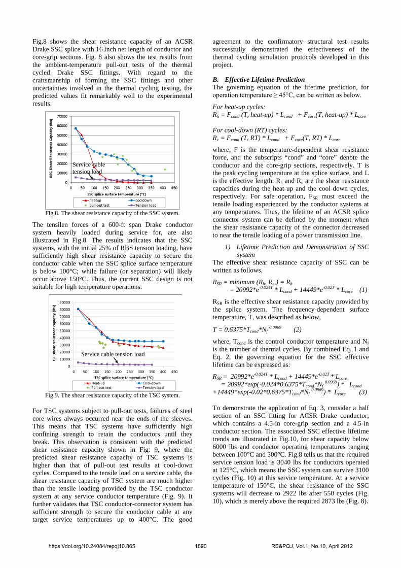
Fig.8 shows the shear resistance capacity of an ACSR Drake SSC splice with 16 inch net length of conductor and core-grip sections. Fig. 8 also shows the test results from the ambient-temperature pull-out tests of the thermal cycled Drake SSC fittings. With regard to the craftsmanship of forming the SSC fittings and other uncertainties involved in the thermal cycling testing, the predicted values fit remarkably well to the experimental results.
Fig.8. The shear resistance capacity of the SSC system.
The tensilen forces of a 600-ft span Drake conductor system heavily loaded during service for, are also illustrated in Fig.8. The results indicates that the SSC systems, with the initial 25% of RBS tension loading, have sufficiently high shear resistance capacity to secure the conductor cable when the SSC splice surface temperature is below 100°C; while failure (or separation) will likely occur above 150°C. Thus, the current SSC design is not suitable for high temperature operations.
Fig.9. The shear resistance capacity of the TSC system.
For TSC systems subject to pull-out tests, failures of steel core wires always occurred near the ends of the sleeves. This means that TSC systems have sufficiently high confining strength to retain the conductors until they break. This observation is consistent with the predicted shear resistance capacity shown in Fig. 9, where the predicted shear resistance capacity of TSC systems is higher than that of pull-out test results at cool-down cycles. Compared to the tensile load on a service cable, the shear resistance capacity of TSC system are much higher than the tensile loading provided by the TSC conductor system at any service conductor temperature (Fig. 9). It further validates that TSC conductor-connector system has sufficient strength to secure the conductor cable at any target service temperatures up to 400°C. The good
agreement to the confirmatory structural test results successfully demonstrated the effectiveness of the thermal cycling simulation protocols developed in this project.
B. Effective Lifetime Prediction The governing equation of the lifetime prediction, for operation temperature ≥ 45°C, can be written as below.
For heat-up cycles: Rh = Fcond (T, heat-up) * Lcond + Fcore(T, heat-up) * Lcore For cool-down (RT) cycles: Rc = Fcond (T, RT) * Lcond + Fcore(T, RT) * Lcore
where, F is the temperature-dependent shear resistance force, and the subscripts “cond” and “core” denote the conductor and the core-grip sections, respectively. T is the peak cycling temperature at the splice surface, and L is the effective length. Rh and Rc are the shear resistance capacities during the heat-up and the cool-down cycles, respectively. For safe operation, FSR must exceed the tensile loading experienced by the conductor systems at any temperatures. Thus, the lifetime of an ACSR splice connector system can be defined by the moment when the shear resistance capacity of the connector decreased to near the tensile loading of a power transmission line.
1) Lifetime Prediction and Demonstration of SSC system
The effective shear resistance capacity of SSC can be written as follows,
RSR = minimum (Rh, Rc,) = Rh = 20992*e-0.024T * Lcond + 14449*e-0.02T * Lcore (1)
RSR is the effective shear resistance capacity provided by the splice system. The frequency-dependent surface temperature, T, was described as below,
T = 0.6375*Tcond*Nf 0.0969 (2)
where, Tcond is the control conductor temperature and Nf is the number of thermal cycles. By combined Eq. 1 and Eq. 2, the governing equation for the SSC effective lifetime can be expressed as:
RSR = 20992*e-0.024T * Lcond + 14449*e-0.02T * Lcore = 20992*exp(-0.024*0.6375*Tcond*Nf 0.0969) * Lcond +14449*exp(-0.02*0.6375*Tcond*Nf 0.0969) * Lcore (3)
To demonstrate the application of Eq. 3, consider a half section of an SSC fitting for ACSR Drake conductor, which contains a 4.5-in core-grip section and a 4.5-in conductor section. The associated SSC effective lifetime trends are illustrated in Fig.10, for shear capacity below 6000 lbs and conductor operating temperatures ranging between 100°C and 300°C. Fig.8 tells us that the required service tension load is 3040 lbs for conductors operated at 125°C, which means the SSC system can survive 3100 cycles (Fig. 10) at this service temperature. At a service temperature of 150°C, the shear resistance of the SSC systems will decrease to 2922 lbs after 550 cycles (Fig. 10), which is merely above the required 2873 lbs (Fig. 8).
Service cable tension load
Service cable tension load
https://doi.org/10.24084/repqj10.865 1890 RE&PQJ, Vol.1, No.10, April 2012

Therefore, the allowable thermal cycles for the 600-ft-span Drake conductor system operated at 125°C and 150°C are 3100 and 550 cycles, respectively, which equal to 1550 and 275 days assuming that there are two thermal cycles per day,. For the service temperature of 100°C, similar analysis results in an effective lifetime of approximately 38 years.
Fig.10. Shear resistance as a function of service temperature and
thermal cycles for SSC connectors used on ACSR Drake conductors..
2) Lifetime Prediction and Demonstration of TSC system
For TSC systems, the effective shear resistance capacity, the frequency-dependent surface temperature, and the governing equation for the effective lifetime can be expressed as RSR = minimum (Rh, Rc,) = Rh
= 27431*e-0.023T * Lcond + 7947*e-0.0007T * Lcore (4)
T = 0.5533*Tcond*Nf 0.0783 (5)
and
RSR = 27431*e-0.023T * Lcond + 7947*e-0.0007T * Lcore
= 27431*exp(-0.023*0.5533*Tcond*Nf 0.0783) * Lcond +7947*exp(-0.0007*0. 5533*Tcond*Nf 0.0783) * Lcore (6)
Fig.11. Shear resistance as a function of service temperature and
thermal cycles for TSC connectors used on ACSR Drake conductors.
A half section of a TSC fitting for ACSR Drake conductors contains a 5-in core-grip section and an approximately 9-in conductor section. The estimated shear resistance for operating temperatures ranging from 70°C to 300°C are illustrated in Fig.11. Note that the lowest shear resistance capacity after 5000 thermal cycles to 300°C is approximately 28642 lbs, which is much higher than the required tension load of 2206 lbs. . These results verify that TSC conductor systems have sufficient shear strength
to secure the conductor cable at any target service temperatures up to 300°C.
5. Conclusions The reliability of ACSR splice connector systems under thermal cycling at high operation temperatures has been investigated in this study. The FEM thermal cycling simulation results of SSC and TSC system show good agreement with degradation trends of experimental data. A numerical simulation protocol has been developed to provide guidance in predicting the effective lifetime of ACSR splice connector system performance. The main findings are: • Compressive residual stress field and the associated
shear resistance capacity within an ACSR splice connector system can serve as a good index for effective lifetime estimation.
• Thermal cycling has significant detrimental effect on the lifetime of SSC and TSC systems, especially under high temperature operation.
• Tension loading needs to be considered in ACSR splice connector system lifetime investigation, especially for consideration in combination with dynamic tension loading.
• Compressive residual stresses during both the cool-down and the heat-up cycles need to be considered when evaluating the ACSR splice connector system performance and lifetime.
• The developed protocol and the associated lifetime prediction models for ACSR splice connector systems will benefit operators of power grids and transmission lines, as well as the conductor system designers regarding safe operations to meet current power demand.
Acknowledgement The Authors would like to thank DOE Office of Electricity Delivery & Energy Reliability and EPRI for funding this project.
References [1] Jy-An Wang, Edgar Lara-Curzio, Thomas King, Joe Graziano, John Chan, “The Integrity of ACSR Full Tension Splice Connector at Higher Operation Temperature”, IEEE Transactions on Power Delivery, 2008,Vol.23(2),pp.1158-1165. [2] Jy-An Wang, John Chan, Joe raziano, “The Lifetime Estimate for ACSR Single Stage Splice Connector Operated at Higher Temperatures”, IEEE Transactions on Power Delivery,2011,Vol.26(3), pp.1317-1325. [3] ANSI C119.4, American National Standard for Electric Connectors, American National Standards Institute, Inc. [4] Ridely Thrash, et. al, Southwire Company Overhead Conductor Manual, Second Edition, Southwire Company, Carrolton, Georgia, 2007.
https://doi.org/10.24084/repqj10.865 1891 RE&PQJ, Vol.1, No.10, April 2012