THE RELATIONSHIP BETWEEN FIBRE ARCHITECTURE AND …€¦ · the relationship between fibre...
7
THE RELATIONSHIP BETWEEN FIBRE ARCHITECTURE AND CRACKING DAMAGE IN A KNITTED FABRIC REINFORCED COMPOSITE. C.R. Rios 1 , S.L. Ogin 1 , C. Lekakou 1 and K.H. Leong 2 . 1 School of Mechanical and Materials Engineering University of Surrey. Guildford, GU2 5XH, England 2 Cooperative Research Center for Advanced Composites Structures Limited 506 Lorimer Street, Fishermen’s Bend, Victoria, 3207, Australia SUMMARY: The relationship between fibre architecture and cracking damage in a knitted fabric reinforced composite has been studied under tensile loading conditions. A novel technique has been employed to make a sandwich laminate, consisting of a knitted fabric layer sandwiched between two 0 o layers. This specimen configuration, together with the transparency of the laminate, enables features of the cracking damage to be related to the fabric architecture. KEYWORDS: damage development, knitted fabric composites, mechanical properties, crack accumulation. INTRODUCTION Knitted fabric reinforced composites are of increasing interest due to the possibility of producing net-shape/near-net-shape preforms, on the one hand, and the exceptional drapeability/formability of the fabrics which allows for forming over a shaped tool of complex shape, on the other [1]. Both of these features follow from the interlooped nature of the reinforcing fibres/yarns. The mechanical properties of knitted fabric are highly orientation-dependent and the final property parameters are also dependent on such factors as the fibre volume fraction and the number of cloths employed to make a laminate [2,3]. Of particular interest in this work is the relationship of the complex fibre architecture to the damage accumulation under load. Leong et al [4] have shown that knitted fabric reinforced composites can show an accumulation of cracks under load in both the course and wale directions, and that the cracking patterns are different in detail for these two directions. They also attempted to relate the cracking damage to the fabric architecture but this is quite complex in laminates fabricated from multiple layers of fabric. In this work, specimens have been made with a single layer of knitted glass fabric sandwiched between unidirectional layers. This configuration enables multiple fracture to occur in the knitted fabric prior to failure so that the damage accumulation can be related to the fabric architecture.
Transcript of THE RELATIONSHIP BETWEEN FIBRE ARCHITECTURE AND …€¦ · the relationship between fibre...

THE RELATIONSHIP BETWEEN FIBREARCHITECTURE AND CRACKING DAMAGE IN A
KNITTED FABRIC REINFORCED COMPOSITE.
C.R. Rios 1, S.L. Ogin 1, C. Lekakou1 and K.H. Leong 2.
1 School of Mechanical and Materials EngineeringUniversity of Surrey. Guildford, GU2 5XH, England
2 Cooperative Research Center for Advanced Composites Structures Limited506 Lorimer Street, Fishermen’s Bend, Victoria, 3207, Australia
SUMMARY: The relationship between fibre architecture and cracking damage in a knittedfabric reinforced composite has been studied under tensile loading conditions. A noveltechnique has been employed to make a sandwich laminate, consisting of a knitted fabriclayer sandwiched between two 0o layers. This specimen configuration, together with thetransparency of the laminate, enables features of the cracking damage to be related to thefabric architecture.
KEYWORDS: damage development, knitted fabric composites, mechanical properties, crackaccumulation.
INTRODUCTION
Knitted fabric reinforced composites are of increasing interest due to the possibility ofproducing net-shape/near-net-shape preforms, on the one hand, and the exceptionaldrapeability/formability of the fabrics which allows for forming over a shaped tool ofcomplex shape, on the other [1]. Both of these features follow from the interlooped nature ofthe reinforcing fibres/yarns. The mechanical properties of knitted fabric are highlyorientation-dependent and the final property parameters are also dependent on such factors asthe fibre volume fraction and the number of cloths employed to make a laminate [2,3]. Ofparticular interest in this work is the relationship of the complex fibre architecture to thedamage accumulation under load.
Leong et al [4] have shown that knitted fabric reinforced composites can show anaccumulation of cracks under load in both the course and wale directions, and that thecracking patterns are different in detail for these two directions. They also attempted to relatethe cracking damage to the fabric architecture but this is quite complex in laminates fabricatedfrom multiple layers of fabric.
In this work, specimens have been made with a single layer of knitted glass fabric sandwichedbetween unidirectional layers. This configuration enables multiple fracture to occur in theknitted fabric prior to failure so that the damage accumulation can be related to the fabricarchitecture.

MATERIALS AND EXPERIMENTAL METHODS
The sandwich specimens were fabricated using a single layer of Milano weft-knit clothproduced from E-glass yarns (2x68 tex) (see Figure 1) and a wet impregnation technique.The knitted cloth was cut to size and fixed inside a steel frame using tape around its edges.The frame was placed in a filament winder so that unidirectional glass tows could be woundaround the frame to produce the sandwich panel. The glass fibres were impregnated with anepoxy resin (Astor Stag Epoxide Resin; Astor Stag NMA curing agent and Ancamine K61Baccelerator). Sandwich panels were made with either the wale direction of the fabricreinforced with unidirectional fibres (termed wale specimens below) or with the coursedirection reinforced (termed course specimens below). The panel dimensions were 250 mm x250 mm and the unidirectional tows on each face of the sandwich panels had a thickness ofabout 1 mm, with an overall panel thickness of about 3.1 mm. The overall fibre volumefraction of the laminates was 0.29, although the fibre volume fraction within the central(knitted fabric) layer was much lower. Coupons 230 mm long and 20 mm wide were cut fromthe panels. Aluminium end tags (50 mm long by 20 mm wide) were used for the tests andstrain gauges were bonded near the centre of the coupons. An Instron 1196 testing machinewas used with a constant cross-head speed of 0.5 mm/min. Load/strain data were collectedusing a datalogger.
Figure 1.- Photograph of the knitted fabric indicating the dimensions in wale and course directions.
RESULTS AND DISCUSSION
Figure 2a shows a typical stress/strain curve for the sandwich specimens loaded in the waledirection and Figure 2b shows the corresponding increase of crack density with strain. Forthese specimens, crack initiation occurs at a strain of about 0.9% although a significantincrease in crack density occurs after a strain of about 1.1%. The crack initiation strain ofabout 0.9 % is in reasonable agreement with the strain to failure of a single layer of knittedfabric reinforced resin tested alone, which was found to be about 0.8%.
Wale
Course
10 mm

Comparing figure 2a and 2b it is clear that the first “knee” in the stress/strain curvecorresponds to the onset of cracking accumulation which produces a crack spacing of about 4mm. A second “knee” corresponds to the development of a crack spacing of 2 mm.
0
50
100
150
200
250
300
350
400
450
0 0.5 1 1.5 2 2.5 3
Strain (%)
Str
ess
(MP
a)
Figure 2a.- Stress vs. strain curve for a wale specimen.
0
0.2
0.4
0.6
0.8
1
1.2
0 0.5 1 1.5 2 2.5 3
Strain (%)
1/2s
mm
-1
Figure 2b.- Crack density variation with strain for a wale specimen.
Figures 3a and 3b show similar plots for a course direction specimen. Here, the cracks initiateat a slightly lower strain (about 0.8 %), although the strain to failure of a single layer wasfound to be a little higher (about 0.9%).
For both the wale and course specimens, the cracks accumulate in a similar fashion to cracksin a cross-ply laminate [5,6]. In the case of the wale specimens however, planar cracks areformed which usually extend from one edge of the coupon to the other. By contrast, in thecourse specimens, the cracks are much more irregular and appear to be branched at higherstrains.

0
50
100
150
200
250
300
350
400
450
0 0.5 1 1.5 2 2.5 3
Strain (%)
Str
ess
(MP
a)
Figure 3a.- Stress vs. strain curve for a course specimen.
0
0.2
0.4
0.6
0.8
1
1.2
0 0.5 1 1.5 2 2.5 3
Strain (%)
1/2s
mm
-1
Figure 3b.- Crack density variation with strain for a course specimen.
Figures 4a and 4b show a plan view of the wale and course specimens near failure where thedifference in the cracking pattern is obvious. As already mentioned above, the cracks in thewale specimens develop initially with a crack spacing of about 4 mm, but subsequent loadingproduces a saturation crack spacing of about 2 mm (at an applied strain of about 1.8 %). Thiscrack spacing is maintained until specimen failure at about 2.5 % strain, although occasionalshort cracks do initiate between the major cracks. The course specimens, on the other hand,show a much smoother increase in crack density up to coupon failure (at an applied strain ofabout 2.4 %) but the crack pattern is much less regular and crack densities in the coursespecimens are more difficult to measure.
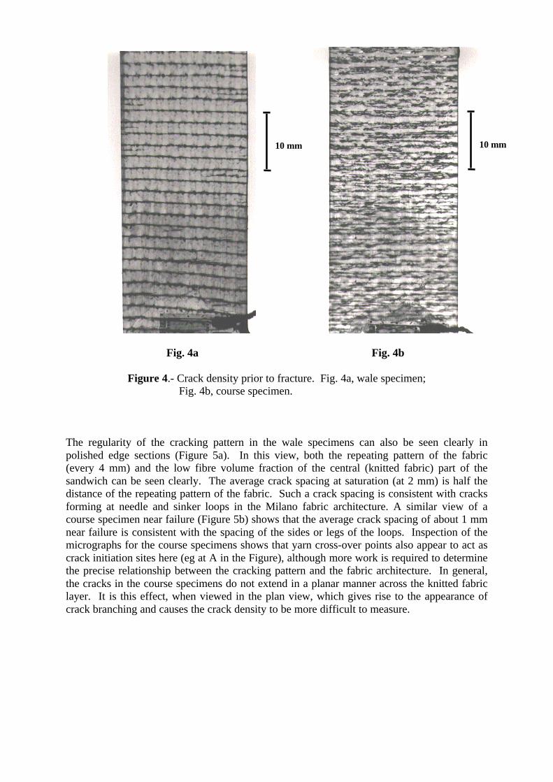
Fig. 4a Fig. 4b
Figure 4.- Crack density prior to fracture. Fig. 4a, wale specimen; Fig. 4b, course specimen.
The regularity of the cracking pattern in the wale specimens can also be seen clearly inpolished edge sections (Figure 5a). In this view, both the repeating pattern of the fabric(every 4 mm) and the low fibre volume fraction of the central (knitted fabric) part of thesandwich can be seen clearly. The average crack spacing at saturation (at 2 mm) is half thedistance of the repeating pattern of the fabric. Such a crack spacing is consistent with cracksforming at needle and sinker loops in the Milano fabric architecture. A similar view of acourse specimen near failure (Figure 5b) shows that the average crack spacing of about 1 mmnear failure is consistent with the spacing of the sides or legs of the loops. Inspection of themicrographs for the course specimens shows that yarn cross-over points also appear to act ascrack initiation sites here (eg at A in the Figure), although more work is required to determinethe precise relationship between the cracking pattern and the fabric architecture. In general,the cracks in the course specimens do not extend in a planar manner across the knitted fabriclayer. It is this effect, when viewed in the plan view, which gives rise to the appearance ofcrack branching and causes the crack density to be more difficult to measure.
10 mm 10 mm

Fig. 5a Fig. 5b
Figure 5.- Micrograph of the edge section. Fig. 5a, wale specimen; Fig. 5b, course specimen.
CONCLUDING REMARKS
A novel specimen, consisting of a single layer of knitted fabric sandwiched between 00 pliesenables the relationship between crack accumulation and fabric architecture to beinvestigated. The technique confirms that cracking patterns in the wale and course directionsare different and are related to fabric architecture. Loading in the course direction produces acrack density which increases with strain to failure. For the wale direction, a saturation crackspacing develops which corresponds to the spacing of the needle and sinker loops.
ACKNOWLEDGEMENTS
The authors are grateful to the Consejo Nacional de Ciencia y Tecnologia (CONACyT)Mexico for the provision of a studentship for C.R. Rios.
A
A
1 mm

REFERENCES
1. Verpoest, I., Gommers, B., Huysmans, G., Ivens, J., Luo, Y., Pandita, S. and Philips, D.“The Potential of Knitted Fabrics as a Reinforcement for Composites”. (1997) Proc ICCM-11,Gold Coast, Australia, vol 1, p108.2. Ramakrishna, S. “Characterisation and Modelling of the Tensile Properties of Plain weft-Knit Fabric-Reinforced Composites” Composites Science and Technology 57 (1997) 1-22.3. Gommers, B., Verpoest I. and Van Houtte, P. “Analysis of Knitted Fabric ReinforcedComposites: Part I. Fibre Orientation Distribution.” Composites Part A 29A (1998) 1579.4. Leong, K.H., Falzon, P.J., Bannister, M. and Herszberg, I. “An Investigation of theMechanical Performance of Weft Knitted Milano Rib Glass/Epoxy Composites.” (1997)Composites Science and Technology. 58 (1998) 239-251.5. Garrett, K.W. and Bailey, J.E. “Multiple Transverse Fracture in 90o Cross-Ply Laminates ofGlass Fibre-Reinforced Polyester.” (1997) J Mater Sci, 12, p1576. Boniface, L., Ogin, S.L. and Smith, P.A. “Strain Energy Release Rates and the FatigueGrowth of Matrix Cracks in Model Arrays in Composite Laminates.” (1991) Proc Roy Soc,A432, p427