The regulations • The products • Sizing • The future ...€¦ · ventilation systems can be...
16
1st Edition Your Step by Step Guide • The regulations • The products • Sizing • The future • Training (57.7) CI/SfB
Transcript of The regulations • The products • Sizing • The future ...€¦ · ventilation systems can be...
1st Edition
Your Step by Step Guide• The regulations• The products• Sizing• The future• Training
(57.7)CI/SfB

Part F and L of the Building Regulations from October 2010
2 T: 0844 856 0594
This document explains how to achieve compliance, looking at the three key areas in detail: Specification and Design, Installation and Commissioning, Operation and Maintenance.
Part F Overview Part F, means of ventilation is hopefully self explanatory and it is the document in which the performance of different systems is covered. Things like airflow rates, noise, occupiers operation etc are all covered here.
The new edition has a few top level changes which may mean something to you (we will cover them in more detail in each section later on) but as an overview they are as follows:
Ventilation RatesFor the first time the ventilation rate of a given property is calculated dependant on the designed infiltration rate. Basically, how much it leaks when the wind blows (anyone who has lived in a drafty house will understand the importance that this has!). There are now two levels of ventilation based on how much they leak air. This is measured in how much air leaks from the building by it’s surface area and the units are m³h of air per m² of building area (m³h/m² ).
1 For properties leakier than 5m³h/m² infiltration.
2 For properties tighter than 5m³h/m² infiltration.
Installation and CommissioningThere is now some guidance on good installation practice and a commissioning guide set out in a supporting document to Part F know as the Domestic Ventilation Compliance Guide. This has been designed to ensure that ventilation not only delivers the required airflow, but also does it efficiently and quietly. This has been designed to link in with competent persons schemes and training programmes run by the industry. See the back page for more information on our BPEC training course which are designed to teach good installation practices.
We would like to welcome you to what we believe is a great place to start if you want to understand the requirements of the October 2010 revision of the Building Regulations.
Part F and L issued in October 2010 place much greater emphasis on effective design, installation and operation of ventilation systems. The objective is to maximise carbon reduction through correctly specified and designed systems, competent installation minimising losses of the systems, verified performance once installed and correct operation by the home owner.
Leaky House
Non Leaky House
Basically, tighter buildings now have an increased ventilation rate.

Part F&L Guide
Part L OverviewPart L, the document covering fuel and power is where the energy efficiency information on ventilation is covered. Putting is simply the new document has improved the energy efficiency targets for buildings by 25%. This affects ventilation equipment as they are part of the SAP calculation and there are now new Target Emission Rate’s (TER’s) set to deliver the 25% improvement over the previous regulations. This is now in line with the Code for Sustainable Homes Level three. There is also an opportunity to save energy through ventilation by using SAP Appendix Q. This is a method by which energy efficient ventilation systems can be selected and the energy benefit be added back into the SAP calculation.
What does this mean for ventilation?Ventilation uses energy in two ways. Firstly, mechanical systems use electricity to power the motors and secondly there is heat loss as air is exhausted from the building which has been heated. This is now dealt with by a minimum energy efficiency level for all ventilation systems being set in a supporting document called The Domestic Building
Services Compliance Guide. There are now for the first time new build and refurbishment minimums in both the amount of electricity a motor can use (minimum specific fan power (SFP)) and a minimum energy efficiency of heat exchangers in systems that can recover the heat.
We recommend that best practice is followed when designing and installing a system, as the product performance is affected by both areas. We can offer support with both elements, please see the back two pages for further information on how we can help.
Ventilation fourThere are systems covered in the building regulations and these are as follows:
System 1 - Intermittent fans and background ventilation
System 2 - Passive stack
System 3 - Continuous mechanical extract ventilation (MEV)
System 4 - Continuous mechanical balanced ventilation with heat recovery
(MVHR)We will be looking at these in more detail under separate sections later in this document.
SummaryThere are now four areas for consideration when selecting ventilation.
• Airflow performance• Minimum energy efficiency limits• Good installation• Use by occupiers
Airflow performance
Minimum energy efficiency limits
Use by occupiers
Good installation
W: www.vent-axia.com �
Things to Remember

Part F changes - Airflows, background ventilators and noise
4 T: 0844 856 0594
There are some considerations dependant on what ventilation system is being used. These are over viewed here but are shown in more detail in the separate sections for each system.
Intermittent Fans and Passive Stack (System 1 and 2)These have different levels of background vents dependant on the infiltration rate of the building.
MEV (System �)Window vents are not need in leakier buildings.
MVHR (System 4)The rate of ventilation can be reduced dependant on the leakage of the building. If the building is leakier than 5m³h/m² then the mechanical ventilation rate is reduced.
NoiseFor the first time, noise is now covered by the building regulations. As our buildings become more energy efficient and more air tight, the amount of noise entering them from outside is reduced. This has the effect of making them much quieter inside. That means that any noise made inside the house will be more noticeable so Part F now suggests a maximum noise level for any continuous system of 35dB(A).
Table 5.1a Extract ventilation rates
Room Intermittent extract Continuous extract Minimum rate Minimum high rate Minimum low rate
Kitchen 30 l/s adjacent to hob 13 l/s or 60 l/s elsewhere Utility room 30 l/s 8 l/s Total extract rate should be at least the whole dwelling ventilation rate given in Table 5.1b
Bathroom 15 l/s 8 l/s
Sanitary 6 l/saccommodation
Table 5.1b Whole dwelling ventilation rates
Number of bedrooms in dwelling 1 2 3 4 5
Whole dwelling 13 17 21 25 29ventilation rate a,b (l/s)
Notes:a. In addition, the minimum ventilation rate should be not less than 0.3 l/s per m2 of internal floor area. (This includes all floors, e.g. for a two-storey building add the ground and first floor areas).b. This is based on two occupants in the main bedroom and a single occupant in all other bedrooms. This should be used as the default value. If a greater level of occupancy is expected add 4 l/s per occupant.
The table below shows the airflow rates as described in Part F
Part F&L Guide
Part L - Minimum efficiencies of motors and heat exchangers
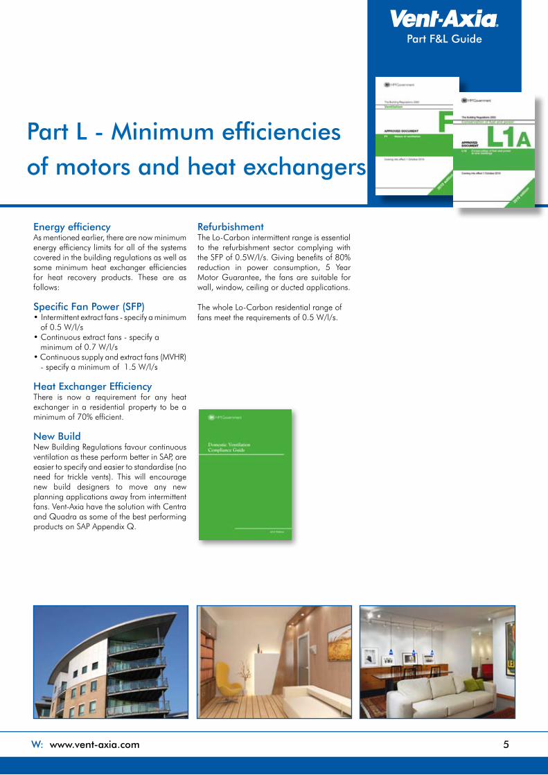
Energy efficiencyAs mentioned earlier, there are now minimum energy efficiency limits for all of the systems covered in the building regulations as well as some minimum heat exchanger efficiencies for heat recovery products. These are as follows:
Specific Fan Power (SFP)• Intermittent extract fans - specify a minimum of 0.5 W/l/s• Continuous extract fans - specify a minimum of 0.7 W/l/s• Continuous supply and extract fans (MVHR) - specify a minimum of 1.5 W/l/s
Heat Exchanger EfficiencyThere is now a requirement for any heat exchanger in a residential property to be a minimum of 70% efficient.
New BuildNew Building Regulations favour continuous ventilation as these perform better in SAP, are easier to specify and easier to standardise (no need for trickle vents). This will encourage new build designers to move any new planning applications away from intermittent fans. Vent-Axia have the solution with Centra and Quadra as some of the best performing products on SAP Appendix Q.
RefurbishmentThe Lo-Carbon intermittent range is essential to the refurbishment sector complying with the SFP of 0.5W/l/s. Giving benefits of 80% reduction in power consumption, 5 Year Motor Guarantee, the fans are suitable for wall, window, ceiling or ducted applications.
The whole Lo-Carbon residential range of fans meet the requirements of 0.5 W/l/s.
W: www.vent-axia.com 5

6 T: 0844 856 0594
System 1 - Intermittent Fans and Background VentilatorsIntermittent extract fan airflow rate based on table 5.1a from the previous page.The design air permeability will determine the equivalent ventilator area as laid out in the below tables.
System 2 Passive Stack Ventilation (PSV)This system relies on the natural stack effect by which warm air rises and is extracted from the wet rooms through 125mm rigid ducts running to ridge height. Trickle vents are required and can be humidity controlled. Internal rooms require ‘assisted’ ventilation i.e. by mechanical ventilation.
Background VentilationMuch larger equivalent areas (up to 50% bigger) are now required for background ventilators when using system 1.
For example a three bed house with a floor area of 100m² a total equivalent area of 65000mm² is required. This may only have 6 windows to fit them in which would mean a free area of 10,833mm in each window. This not only takes up a lot of space in each window frame and looks unsightly, but the window fabricator will charge to fit each one and this example could require three vents on each window.
Key increase mm2
Increases from the
requirements of ADF 2006
5000
10000
15000
20000
Total floor Number of bedrooms b
area (m2) 1 2 � 4 5
50 35000 40000 50000 60000 65000
51-60 35000 40000 50000 60000 65000
61-70 45000 45000 50000 60000 65000
71-80 50000 50000 50000 60000 65000
81-90 55000 60000 60000 60000 65000
91-100 65000 65000 65000 65000 65000
100 Add 7000 mm2 for every additional 10m2 floor area
A - Total equivalent ventilator area ª (mm2) for a dwelling with any design air permeability.
Total floor Number of bedrooms b
area (m2) 1 2 � 4 5
50 25000 35000 45000 45000 55000
51-60 25000 30000 40000 45000 55000
61-70 30000 30000 30000 45000 55000
71-80 35000 35000 35000 45000 55000
81-90 40000 40000 40000 45000 55000
91-100 45000 45000 45000 45000 55000
100 Add 5000 mm2 for every additional 10m2 floor area
B -Alternative guidance on total equivalent ventilator area3 (mm2) for a dwelling with a designed air permeability leakier than (>) 5m3/ (h.m2) at 50 Pa.
Notes:a. The equivalent area of a background ventilator should be determined at 1 Pa pressure difference, using the appropriate test method given in Table 5.3b. This is based on two occupants in the main bedroom and a single occupant in all other bedrooms. For a greater level of occupancy, assume a greater number of bedrooms (i.e. assume an extra bedroom per additional person). For more than five bedrooms, add an additional 10000 mm2 per bedroom
System 1 and 2 - Intermittent Fans & Passive Stack

Part F&L Guide
Range FeaturesModels: Basic/Timer/Humidity - Installation options.
Low power consumption - Part L Compliant
Quiet running
Back draught shutters included
Modern aesthetics.
Ball bearing motors for vertical or horizontal application
5 year motor guarantee
Wall, ceiling, panel and window mounting options available.
•
•
•
•
•
•
•
•
Airflow Rates - Intermittent
Part F and L CompliantThe new requirement for minimum specific fan powers means that no intermittent fan can use more than 0.5 W/l/s. Vent-Axia offer a fully compliant Lo-Carbon intermittent range which meets both Part F and Part L.
Product - Intermittent l/s Watts SFP (W/l/s)
VA100 (Bathrooms) 25 6.5 0.26VA100 SELV (Bathroom) 25 6.5 0.26Silhouette 100 (Bathroom) 24 6.5 0.27Silhouette 100 SELV (Bathroom) 26 7.5 0.29Minivent 31 6.5 0.21Vent-A-Light 31 6.5 0.21Solo Plus* VAR VAR 0.50Solo Plus SELV * VAR VAR 0.50VA150 (Kitchen) 64 11.5 0.18Silhouette 150 (Kitchen) 67 8.2 0.12
* VAR = Variable speed settings and controls so lowest SFP quoted
Lo-Carbon Range
Lo-Carbon Fan Range Features
Lo-Carbon Solo Plus
Lo-Carbon Silhouette
W: www.vent-axia.com �
Part LCompliant
Part FCompliant
Part LCompliant

8 T: 0844 856 0594
System � – Continuous Mechanical Extract (MEV)There are two ways in which to comply with system 3: Centralised (MEV) or Decentralised (dMEV).MEV incorporates a single unit that extracts stale air to atmosphere from all the wet rooms via ducting.Decentralised MEV requires continuous running extract fans mounted in all wet rooms in much the same way as a traditional fan is mounted.
As shown on page four, rates as per table 5.1b for the continuous systems are much lower than the intermittent ventilation, and in kitchens particularly the rate falls form 60l/s to 13l/s. This can remove the requirement for noisy fans or cookerhoods completely.
Reduced background VentilatorsAn additional benefit is through a reduction in the number of background vents needed. If the design air permeability is <5m3/(h.m2)@50Pa, background ventilators are required in habitable rooms at 2500mm² only. This is one small vent. If design air permeability is >5m3/(h.m2)@50Pa there is no requirement for background ventilators at all. This gives a really big benefit of not having to fit a large number of unsightly window vents in, as required with intermittent systems.
Energy efficiencyThe Domestic Building Services Compliance Guide states a maximum specific fan power of 0.7 W/l/s for MEV systems. These can also be SAP Appendix Q eligible which enables selection during the SAP calculation (there is an eligible product list embedded within the SAP software programmes). This enables the difference between the specific product and the default settings within SAP.
Vent-Axia Lo-Carbon Multivent ranges incorporates energy efficient EC/DC motors providing SFP’s down to 0.18W/l/s which is up to 75% savings over the default 0.7 W/l/s in SAP. This low specific fan power (SFP) makes it one of the most efficient MEV products available.
In much the same way, dMEV can be applied and Vent-Axia Lo-Carbon Centra also provides SFP’s down to 0.18W/l/s which is up to 75% savings over the default 0.7W/l/s in SAP. This also makes it one of the most efficient dMEV products available
InstallationThe new 2010 regulations also require that systems are installed and commissioned correctly. To help, we provide training courses. See the training scheme section at the end of this brochure.
System � MEV and dMEV

Part F&L Guide
Range FeaturesSingle fan for use in toilets, bathrooms, utility rooms and kitchens
Meets Building Regulations for intermittent or continuous use
Guaranteed installed performance
Part F complaint - meets airflow rates in table 5.1
Part L complaint - SFP 0.38W/l/s
Suitable for wall, ceiling and panel mounting.
Filterless technology and maintenance free
Lo-Carbon motors offering 90% energy savings and long life
•
•
•
•
•
•
•
•
Range FeaturesReduces your carbon footprint
SAP Appendix Q Eligible
Specific fan power down to 0.18 W/l/s
LS Boost connection
Integral humidity sensor available
Ultra quiet - acoustically lined for low noise levels
Complies with Building Regulations Part F (System 3)
•
•
•
•
•
•
•
Lo-Carbon Centra Lo-Carbon Quadra Lo-Carbon Multivent MVDC-MS
SAP Appendix Q Test Results
Exhaust Terminal Total Flow Specific FanConfiguration Rate (l/s) Power (W/l/s) Kitchen +1 additional wet room 21.0 0.24Kitchen +2 additional wet room 29.0 0.18Kitchen +3 additional wet room 37.0 0.21
W: www.vent-axia.com 9
Part LCompliant
Part FCompliant
Part LCompliant
Range FeaturesPart F compliant, meets required airflow rates in table 5.1.
Part L compliant - SFP is 0.18W/l/s.
SAP Appendix Q eligible
Quietest dMEV available.
Discreet, tasteful styling.
Single fan for use in all applications.
IPX4 rated - IPX7 rated (SELV)
Lo-Carbon motor offering 90% energy savings and long life.
5 year motor guarantee
Suitable for wall, ceiling, panel and window mounting.
•
•
•
•
•
•
•
•
•
•
Lo-Carbon Multivent MVDC-MS
10 T: 0844 856 0594
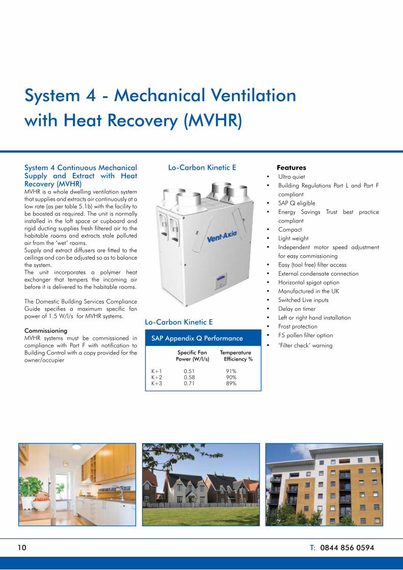
System 4 Continuous Mechanical Supply and Extract with Heat Recovery (MVHR)MVHR is a whole dwelling ventilation system that supplies and extracts air continuously at a low rate (as per table 5.1b) with the facility to be boosted as required. The unit is normally installed in the loft space or cupboard and rigid ducting supplies fresh filtered air to the habitable rooms and extracts stale polluted air from the ‘wet’ rooms.Supply and extract diffusers are fitted to the ceilings and can be adjusted so as to balance the system.The unit incorporates a polymer heat exchanger that tempers the incoming air before it is delivered to the habitable rooms.
The Domestic Building Services Compliance Guide specifies a maximum specific fan power of 1.5 W/l/s for MVHR systems.
CommissioningMVHR systems must be commissioned in compliance with Part F with notification to Building Control with a copy provided for the owner/occupier
•
FeaturesUltra quietBuilding Regulations Part L and Part F compliantSAP Q eligibleEnergy Savings Trust best practice compliantCompactLight weightIndependent motor speed adjustment for easy commissioningEasy (tool free) filter accessExternal condensate connectionHorizontal spigot optionManufactured in the UKSwitched Live inputsDelay on timerLeft or right hand installationFrost protectionF5 pollen filter option
‘Filter check’ warning
••
••
•••
•••••••••
•
System 4 - Mechanical Ventilation with Heat Recovery (MVHR)
Lo-Carbon Kinetic E
SAP Appendix Q Performance Specific Fan Temperature Power (W/l/s) Efficiency % K+1 0.51 91%K+2 0.58 90%K+3 0.71 89%
Lo-Carbon Kinetic E

Part F&L Guide
Lo-Carbon Sentinel Kinetic Plus
Additional Sentinel Features Programmable summer bypass
Integrated digital controller for simple and accurate commissioning
Plug and play controls: Humidistat, Vent-Wise, PIR
Wired remote control and wireless boost options
Volt-free inputs
Adjustable delay-off timer
BMS connectivity
Self diagnosis for simplified fault finding
0v to 10v proportional control
Purge setting
Cooker hood option
•
•
•
•
•
•
•
•
•
•
•
SAP Appendix Q Performance Specific Fan Temperature Power (W/l/s) Efficiency % K+1 0.56 92%K+2 0.49 92%K+3 0.52 91%K+4 0.57 90%K+5 0.62 90%K+6 0.70 89%K+7 0.80 89%
Sentinel Kinetic Plus
SAP Appendix Q Performance Specific Fan Temperature Power (W/l/s) Efficiency % K+1 0.72 92%K+2 0.74 91%K+3 0.81 90%K+4 0.93 88%K+5 1.07 87%
Sentinel Kinetic
W: www.vent-axia.com 11
Lo-Carbon Sentinel Kinetic
Additional Kinetic Plus Features
150mm spigots with 180mm and 200mm options
Constant volume version
Up to 111 l/s (400m3/hr) at 150Pa
Hinged filter for simplified access
•
•
•
•
Part LCompliant
Part FCompliant
Part LCompliant
12 T: 0844 856 0594
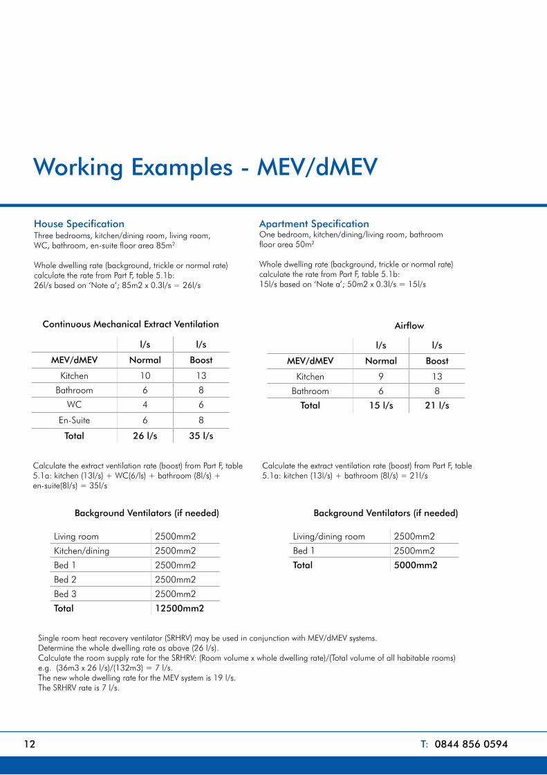
Working Examples - MEV/dMEV
House Specification Three bedrooms, kitchen/dining room, living room, WC, bathroom, en-suite floor area 85m2
Whole dwelling rate (background, trickle or normal rate)calculate the rate from Part F, table 5.1b: 26l/s based on ‘Note a’; 85m2 x 0.3l/s = 26l/s
Apartment SpecificationOne bedroom, kitchen/dining/living room, bathroomfloor area 50m2
Whole dwelling rate (background, trickle or normal rate)calculate the rate from Part F, table 5.1b: 15l/s based on ‘Note a’; 50m2 x 0.3l/s = 15l/s
l/s l/s
MEV/dMEV Normal Boost
Kitchen 10 13
Bathroom 6 8
WC 4 6
En-Suite 6 8
Total 26 l/s �5 l/s
Continuous Mechanical Extract Ventilation
Living room 2500mm2
Kitchen/dining 2500mm2
Bed 1 2500mm2
Bed 2 2500mm2
Bed 3 2500mm2
Total 12500mm2
Background Ventilators (if needed)
Calculate the extract ventilation rate (boost) from Part F, table 5.1a: kitchen (13l/s) + WC(6/ls) + bathroom (8l/s) + en-suite(8l/s) = 35l/s
Calculate the extract ventilation rate (boost) from Part F, table 5.1a: kitchen (13l/s) + bathroom (8l/s) = 21l/s
l/s l/s
MEV/dMEV Normal Boost
Kitchen 9 13
Bathroom 6 8
Total 15 l/s 21 l/s
Airflow
Living/dining room 2500mm2
Bed 1 2500mm2
Total 5000mm2
Background Ventilators (if needed)
Single room heat recovery ventilator (SRHRV) may be used in conjunction with MEV/dMEV systems. Determine the whole dwelling rate as above (26 l/s).Calculate the room supply rate for the SRHRV: (Room volume x whole dwelling rate)/(Total volume of all habitable rooms) e.g. (36m3 x 26 l/s)/(132m3) = 7 l/s. The new whole dwelling rate for the MEV system is 19 l/s. The SRHRV rate is 7 l/s.

Part F&L Guide
Working Examples - MVHR
l/s l/s
Supply Normal Boost
Living room 6 8
Kitchen/dining 7 9
Bed 1 5 6
Bed 2 4 6
Bed 3 4 6
26 l/s �5 l/s
l/s l/s
Supply Normal Boost
Living/dining room 9 13
Bed 1 6 8
15 l/s 21 l/s
House Dimensions:Ground floor8.5m x 5m x 2.4m (room height)First Floor8.5m x 5m x 2.4m (room height)Total dwelling volume = 204m3204m3 x 0.04l(s.m3) = 8.2 l/s infiltration
Whole dwelling rate – Infiltration26 l/s - 8.2 l/s = 1�.8 l/s
Apartment Dimensions:Ground floor10m x 5m x 2.4m (room height)Total dwelling volume = 120m3120m3 x 0.04l(s.m3) = 4.8 l/s infiltration
Whole dwelling rate – Infiltration15 l/s - 4.8 l/s = 10.2 l/s
House Specification Three bedrooms, kitchen/dining room, living room, WC, bathroom, en-suite floor area 85m2
Whole dwelling rate (background, trickle or normal rate)calculate the rate from Part F, table 5.1b: 26l/s based on ‘Note a’; 85m2 x 0.3l/s = 26l/s
Apartment SpecificationOne bedroom, kitchen/dining/living room, bathroomfloor area 50m2
Whole dwelling rate (background, trickle or normal rate)calculate the rate from Part F, table 5.1b: 15l/s based on ‘Note a’; 50m2 x 0.3l/s = 15l/s
Calculate the extract ventilation rate (boost) from Part F, table 5.1a: kitchen (13l/s) + WC (6/ls) + bathroom (8l/s) + en-suite (8l/s) = 35l/s
Calculate the extract ventilation rate (boost) from Part F, table 5.1a: kitchen (13l/s) + bathroom (8l/s) = 21l/s
For buildings leakier than 5m3/(h.m2), you must subtract natural infiltration from the whole dwelling (normal) rate: calculate the internal volume of the dwelling. Multiply the internal volume by 0.04 l/(s.m3) subtract this volume from the whole dwelling rate.
l/s l/s
Extract Normal Boost
Kitchen 9 13
Bathroom 6 8
Total 15 l/s 21 l/s
Airflow
l/s l/s
Extract Normal Boost
Kitchen 10 13
Bathroom 6 8
WC 4 6
En-Suite 6 8
Total 26 l/s �5 l/s
Airflow
W: www.vent-axia.com 1�
14 T: 0844 856 0594
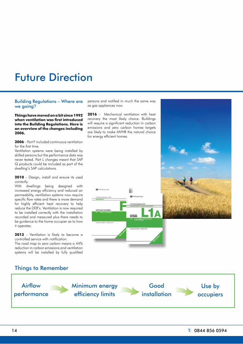
Future Direction Building Regulations – Where are we going?
Things have moved on a bit since 1992 when ventilation was first introduced into the Building Regulations. Here is an overview of the changes including 2006. 2006 – Part F included continuous ventilation for the first time. Ventilation systems were being installed by skilled persons but the performance data was never tested. Part L changes meant that SAP Q products could be included as part of the dwelling’s SAP calculations.
2010 – Design, install and ensure its used correctly.With dwellings being designed with increased energy efficiency and reduced air permeability, ventilation systems now require specific flow rates and there is more demand for highly efficient heat recovery to help reduce the DER’s. Ventilation is now required to be installed correctly with the installation recorded and measured plus there needs to be guidance to the home occupier as to how it operates.
2013 – Ventilation is likely to become a controlled service with notification. The road map to zero carbon means a 44% reduction in carbon emissions and ventilation systems will be installed by fully qualified
persons and notified in much the same way as gas appliances now.
2016 – Mechanical ventilation with heat recovery the most likely choice. Buildings will require a significant reduction in carbon emissions and zero carbon homes targets are likely to make MVHR the natural choice for energy efficient homes.
Airflow performance
Minimum energy efficiency limits
Use by occupiers
Good installation
Things to Remember

Part F&L Guide
Training Scheme
Domestic Ventilation Systems Installer Training
Become a Qualified Installer with your Ventilation Partner
Vent-Axia is now offering a BPEC course deigned to meet the requirements in the Domestic Ventilation Compliance Guide 2010 for the installation, inspection, testing, commissioning and provision of information for Fixed Domestic Systems for both new and existing residential buildings.
The course is recognised by all Competent Persons Schemes within the industry including HVCA and NICEIC.
The course will train you to:• Install Domestic Ventilation Systems in a safe and workmanlike manner.• Inspect and test Domestic Ventilation Systems • Commission and provide information on Domestic Ventilation Systems
To be eligible for this course you must hold or be taking a formal qualification such as N/SVQ level 3, or have a number of years experience in Plumbing, Heating, Electrical Ventilation installation
The course will be run over two days:The 1st day will be theoretical with candidates working
with the trainer through the BPEC training manual.
The 2nd is taken up with practical exercises including the commissioning of a working MVHR system.
At the end of the course, there is an open book multiple choice assessment that each individual candidate needs to pass.
What does the course fee include?
The course fee includes both days training with lunch, your personal copy of the training manual which will be sent in advance of your starting date and your certification upon successful completion which lasts five years. Hotel accommodation is not included.
What do I need to do to register?
If you meet the requirements above then the registration can be completed on line. Upon registration you will be emailed confirmation and an order number to retain for any future correspondence. The manual will also be sent for you to study before the course starts.
What do I need to bring?
The manual must be bought with you to the training along with two passport photographs which will be needed for your registration.
When and where are the courses run?
The dates are shown on the next page along with the last registration date to ensure you receive the course materials in time to prepare. Course timings are 9.30am to 5.00pm on both days. The course is held at our new BPEC approved training facility at Crawley. The cost of the course is £395.00 including VAT + postage.
W: www.vent-axia.com 15

VENT-AXIA CONTACT NUMBERSFree technical, installation and sales advice is available
Sales Centre:Domestic & Commercial
Sales Tel: 0844 856 0590
Sales Fax: 01293 565169
Tech Support Tel: 0844 856 0594
Tech Support Fax: 01293 539209
Industrial Sales Tel: 0844 856 0591
Sales Fax: 01293 534898
Tech Support Tel: 0844 856 0595
Tech Support Fax: 01293 455197
Web: www.vent-axia.com
Email: [email protected]
By Appointment to H.M. The QueenSuppliers of Unit Ventilation Equipment
Vent-Axia, Crawley, West Sussex
402244/0511
Supply & ServiceAll sales made by Vent-Axia Limited are made only upon
the terms of the Company’s Conditions of Sale, a copy
of which may be obtained on request. As part of the
policy of continuous product improvement Vent-Axia
reserves the right to alter specifications without notice.
VENT-AXIA CONTACT NUMBERSFree technical, installation and sales advice is available
Sales Centre:Domestic & Commercial
Sales Tel: 0844 856 0590
Sales Fax: 01293 565169
Tech Support Tel: 0844 856 0594
Tech Support Fax: 01293 539209
Industrial Sales Tel: 0844 856 0591
Sales Fax: 01293 534898
Tech Support Tel: 0844 856 0595
Tech Support Fax: 01293 455197
Web: www.vent-axia.com
Email: [email protected]
By Appointment to H.M. The QueenSuppliers of Unit Ventilation Equipment
Vent-Axia, Crawley, West Sussex
Supply & ServiceAll sales made by Vent-Axia Limited are made only upon
the terms of the Company’s Conditions of Sale, a copy
of which may be obtained on request. As part of the
policy of continuous product improvement Vent-Axia
reserves the right to alter specifications without notice.