THE RECOVERY OF MANGANESE FROM LOW GRADE …congnghe-sx.com/upload/files/American-Manganese... ·...
96
KEMETCO RESEARCH INC., #445 – 5600 Parkwood Way, Richmond, BC V6V 2M2 CANADA Tel: +1 604 273 3600 E-mail: [email protected] Website: www.kemetco.com THE RECOVERY OF MANGANESE FROM LOW GRADE RESOURCES: BENCH SCALE METALLURGICAL TEST PROGRAM COMPLETED Prepared for: American Manganese Inc. 2A – 15782 Marine Drive White Rock, BC V4B 1E6 CANADA Prepared by: Norman Chow, P.Eng., Anca Nacu, PhD, Doug Warkentin, P.Eng., Igor Aksenov, Hoe Teh, P.Eng. Kemetco Research Inc. #445 - 5600 Parkwood Way Richmond, BC V6V 2M2 CANADA August 19, 2010 IRAP Project No.: 712681 © 2010 Kemetco Research Inc. All rights reserved.
Transcript of THE RECOVERY OF MANGANESE FROM LOW GRADE …congnghe-sx.com/upload/files/American-Manganese... ·...

KEMETCO RESEARCH INC., #445 – 5600 Parkwood Way, Richmond, BC V6V 2M2 CANADA Tel: +1 604 273 3600 E-mail: [email protected] Website: www.kemetco.com
THE RECOVERY OF MANGANESE FROM LOW GRADE RESOURCES: BENCH SCALE METALLURGICAL TEST PROGRAM COMPLETED
Prepared for: American Manganese Inc. 2A – 15782 Marine Drive White Rock, BC V4B 1E6 CANADA Prepared by: Norman Chow, P.Eng., Anca Nacu, PhD, Doug Warkentin, P.Eng., Igor Aksenov, Hoe Teh, P.Eng. Kemetco Research Inc. #445 - 5600 Parkwood Way Richmond, BC V6V 2M2 CANADA
August 19, 2010
IRAP Project No.: 712681
© 2010 Kemetco Research Inc. All rights reserved.

KEMETCO RESEARCH INC., #445 – 5600 Parkwood Way, Richmond, BC V6V 2M2 CANADA Tel: +1 604 273 3600 E-mail: [email protected] Website: www.kemetco.com
August 19, 2010
Mr. Larry W. Reaugh President & CEO American Manganese Inc. 2A 15782 Marine Drive White Rock, BC V4B 1E6 CANADA Dear Mr. Reaugh:
Re: Kemetco’s Final Report of the Completed Bench Scale Test Program
I am pleased to present this technical report which summarizes Kemetco’s bench scale test work on American Manganese Inc’s Artillery Peak Project. The work shows conceptual flowsheets for an integrated novel process to produce high grade electrolytic manganese metal from the Artillery Peak Resource in Arizona. This is a new process containing proprietary intellectual know-how which is the subject of patent protection as we discussed previously. Kemetco made extensive use of existing reports made available from American Manganese Inc., developed and extended the known state of the art through its in-house expertise and resources to achieve what we believe is a totally new conceptual process which provides a sound basis for future work. As per your request, Kemetco is preparing a proposal to extend this project to include continuous small scale pilot plant demonstration to confirm and extend existing data. I trust this is satisfactory.
Yours Truly,
Norman Chow, M.A.Sc., P.Eng President
THE RECOVERY OF MANGANESE FROM LOW GRADE RESOURCES: BENCH SCALE METALLURGICAL TEST PROGRAM COMPLETED i
KEMETCO RESEARCH INC., #445 – 5600 Parkwood Way, Richmond, BC V6V 2M2 CANADA Tel: +1 604 273 3600 E-mail: [email protected] Website: www.kemetco.com
EXECUTIVE SUMMARY
American Manganese Inc has developed a low-cost, environmentally friendly hydrometallurgical process to recover manganese (Mn) from lower grade resources containing pyrolusite (MnO2), psilomelane and other four valent Mn oxides. This report describes the results of a metallurgical test program contracted by American Manganese to Kemetco Research Inc. The test program was partially funded by the Canadian Government through the National Research Council, Industrial Research Assistance Program (NRC-IRAP) for development work conducted over a one year period.
The purpose of this program has been to conduct bench scale testing of unit operations, that when combined, form the basis of an innovative conceptual process flow sheet to process lower grade Mn resources into high purity Mn metal in an economically viable manner. The process is designed to treat 3500 metric tonnes per day of resource and will produce 141 metric tonnes per day of Mn metal product, and 366 metric tonnes per day of anhydrous sodium sulphate (Na2SO4) crystal by-product.
Treatment of the lower grade American Manganese resource which contains, on average 4% to 7% Mn by weight is carried out in a hydrometallurgical process, where four valent Mn is readily leachable by SO2 dissolved in water. The hydrometallurgical processing of lower grade material avoids high temperature reduction roasting that is conventionally used in processing high grade material to render the manganese to be acid leachable using sulphuric acid (H2SO4). High temperature roasting is energy intensive and would not be economical for lower grade material.
The conceptual process flow sheet developed during this test program is based on a unique application of commercially available process equipment. As such, the process is deemed to be robust, energy efficient, uses minimal water and in addition to production of electrolytic manganese metal will also produce a saleable anhydrous sodium sulphate by-product. The energy to recover water and destroy dithionates is approximately balanced with the energy produced by burning of sulphur (S) to produce SO2. High energy requirements for these applications were a major challenge facing prior art. Dithionate destruction yields SO2 which can be recycled to the leaching stage and use of water is minimized thru production of solid tailings which can be returned to worked out areas of the open pit.
Key aspects of the process flowsheet are as follows:
Sulphur Burning
• SO2 leachant is produced on-site by burning elemental sulphur with 20% excess air. • Heat exchanging the exhaust gases from the sulphur burner will produce 20 tonnes
per hour of steam at 400 oC and 45 bar pressure. • In a condensing turbine, this steam can produce 5 MW of continuous electrical power.

THE RECOVERY OF MANGANESE FROM LOW GRADE RESOURCES: BENCH SCALE METALLURGICAL TEST PROGRAM COMPLETED ii
KEMETCO RESEARCH INC., #445 – 5600 Parkwood Way, Richmond, BC V6V 2M2 CANADA Tel: +1 604 273 3600 E-mail: [email protected] Website: www.kemetco.com
Leaching
• The Mn mineral in the resource sample provided by American Manganese is primarily
pyrolusite and wad (MnO2), in which the Mn has a 4+ valence. The insoluble 4+ valence species of Mn can be readily reduced to soluble 2+ with an SO2 reducing agent dissolved in water.
• Leaching studies performed on American Manganese resources of large particle size (greater than 9.5 mm) with dilute SO2 in stirred tanks indicates that the material is readily leachable, with Mn extractions greater than 90% achieved.
• The material is friable and large particles break down easily during stirred tank leaching. As such crushing and grinding to a fine particle size prior to leaching is not necessary.
• After leaching, the Mn in solution can be separated from the leach residue using a counter current decantation (CCD) circuit that is typically used in mineral processing operations.
Leachant Purification
• Solution purification is performed in two stages. In the first stage, the solution pH is
adjusted to above 6 to precipitate aluminum (Al), arsenic (As) and most of the iron (Fe) and silica (SiO2). Air/oxygen sparging during the pH adjustment will improve the Fe removal, by oxidizing the ferrous iron to its ferric form. In the second stage, sulphide precipitation will remove the zinc (Zn), providing a solution of sufficient purity to process into a saleable product.
• The resource material can be used in the purification stage, by providing sufficient alkalinity to achieve a pH around 6 and precipitate a substantial amount of impurities from solution.
Mn Production
• Mn is separated from the pregnant leach solution (PLS) by precipitation quantitatively
as manganese carbonate (MnCO3). This is achieved by mixing sodium carbonate (Na2CO3) with the PLS solution.
• Na2SO4 and sodium dithionate (Na2S2O6) solution by-product is produced during the precipitation of MnCO3.
• Dissolving the MnCO3 with recycled electrolyte produces a Mn containing solution that is conducive to producing high grade Mn metal.
• A scoping electrowinning test using the American Manganese purified leachate yielded a Mn metal product of greater than 99% purity.
• Using typical commercial electrowinning conditions, a sheet of manganese metal was plated over a 24 hour period at a current efficiency of up to 67%. This represents typical commercial performance.
• The Mn metal was plated without the addition of toxic selenium (Se), which is known to improve current efficiency.

THE RECOVERY OF MANGANESE FROM LOW GRADE RESOURCES: BENCH SCALE METALLURGICAL TEST PROGRAM COMPLETED iii
KEMETCO RESEARCH INC., #445 – 5600 Parkwood Way, Richmond, BC V6V 2M2 CANADA Tel: +1 604 273 3600 E-mail: [email protected] Website: www.kemetco.com
Water Recovery & Dithionate Destruction
• Most of the water used in the process becomes Na2SO4 and Na2S2O6 solution which
is produced during the recovery of MnCO3 by precipitation. • Water recovery from this solution can be achieved with high energy efficiency
because of the unique solubility characteristics of Na2SO4, enabling the majority of Na2SO4 to be crystallized as sodium sulphate decahydrate (Na2SO4⋅10H2O) by cooling the solution. This method is significantly more energy efficient than standard evaporation since it avoids latent heat requirements which accounts for about 85% of the energy required to evaporate water from a starting temperature of 25 oC.
• Na2S2O6 will report with the Na2SO4⋅10H2O crystals and can be calcined with high energy efficiency since the majority of water has been removed. Calcining Na2S2O6 will produce anhydrous Na2SO4 and recover SO2 which can be recycled back to the leach.
Tailings
• Solid tailings with minimum water content are produced by filtration of the final CCD
underflow material, minimizing water requirements for the overall process. • The solid tailings produced from test work were shown to be benign by the Toxicity
Characteristic Leaching Procedure (TCLP).
Future Developments
• Proof of concept was achieved by using a bioreactor technology owned by Kemetco
to recover H2S from Na2S2O6. The H2S can be burned to generate energy and recover SO2 for leaching. Further development work is required to determine if the reaction rates are adequate for integration into the overall process. Implementation of this technology would further improve the efficiency of the overall process.
• Minor adjustments to the flowsheet developed will enable the production of other products such as ferromanganese or electrolytic manganese dioxide if desired.
Based on the successful test work, conceptual flowsheets have been developed which include applications of novel, proprietary, innovative technology to minimize process operating costs through low water use, low overall energy use and economic destruction of unwanted by-products. Heat produced from burning of sulphur to make SO2 is essentially in balance with energy required within the process, excluding the energy required for electrowinning. Waste products are minimized enabling cash costs of production of Mn metal to be significantly lower than costs needed to produce high grade Mn metal from traditional processes. Accordingly, American Manganese Inc. has requested Kemetco to file application for patent protection. American Manganese is grateful for the financial support given by the Canadian Government’s National Research Council under its IRAP program.

THE RECOVERY OF MANGANESE FROM LOW GRADE RESOURCES: BENCH SCALE METALLURGICAL TEST PROGRAM COMPLETED iv
KEMETCO RESEARCH INC., #445 – 5600 Parkwood Way, Richmond, BC V6V 2M2 CANADA Tel: +1 604 273 3600 E-mail: [email protected] Website: www.kemetco.com
TABLE OF CONTENTS
1 INTRODUCTION ....................................................................................................... 1
1.1 BACKGROUND .......................................................................................... 2
2 PROCESS FLOWSHEETS ....................................................................................... 7
2.1 AMERICAN MANGANESE PROCESS FLOWSHEET ............................... 7 2.2 ALTERNATIVE PROCESS FLOWSHEET WITH BIORECTOR TO
RECOVER SO2, ENERGY AND NaHCO3 ................................................ 14 2.3 OTHER PRODUCTS POSSIBLE FROM THE AMERICAN MANGANESE
PROCESS ................................................................................................ 17 2.3.1 Ferromanganese ........................................................................ 17 2.3.2 Electrolytic Manganese Dioxide (EMD) ...................................... 17
3 EXPERIMENTAL RESULTS AND CALCULATIONS ............................................ 18
3.1 SAMPLE PREPARATION AND ANALYSIS ............................................. 18 3.2 SULPHUR BURNING ............................................................................... 19
3.2.1 Description of Operation ............................................................ 19 3.2.2 Stoichiometry and Mass Balance ............................................... 20 3.2.3 Heat and Power Generation Calculations .................................. 20
3.3 REDUCTIVE LEACHING WITH SO2 ........................................................ 21 3.3.1 Factors Influencing the Manganese Extraction and Dithionate
Formation ................................................................................... 24 3.3.2 Stirred Tank Counter Current Leaching with Concentrated SO2 30 3.3.3 Stirred Tank with Dilute SO2 ...................................................... 31 3.3.4 Column Leach Test with Dilute SO2 ........................................... 33
3.4 SOLID LIQUID SEPARATION .................................................................. 34 3.4.1 Flocculant Screening ................................................................. 35 3.4.2 Preliminary Leached Ore Thickener and CCD Sizing ................ 41 3.4.3 Preliminary Counter Current Decantation Wash Sizing ............. 44 3.4.4 Toxicity Characteristic Leaching Procedure on Tailings ............ 46

THE RECOVERY OF MANGANESE FROM LOW GRADE RESOURCES: BENCH SCALE METALLURGICAL TEST PROGRAM COMPLETED v
KEMETCO RESEARCH INC., #445 – 5600 Parkwood Way, Richmond, BC V6V 2M2 CANADA Tel: +1 604 273 3600 E-mail: [email protected] Website: www.kemetco.com
3.5 PREGNANT LEACHATE PURIFICATION ............................................... 47 3.6 MANGANESE CARBONATE PRECIPITATION ....................................... 49 3.7 WATER RECOVERY, ANHYDROUS SODIUM SULPHATE
PRODUCTION AND DITHIONATE DESTRUCTION ............................... 53 3.7.1 Preliminary Mass Balance ......................................................... 55 3.7.2 Calculated Preliminary Energy Balance ..................................... 57 3.7.3 Preliminary Energy Balance Using Data Provided by a
Commercial Supplier of Sodium Sulphate Production Plants .... 58 3.7.4 Comparing Energy Balance with Data from a Commercial
Sodium Sulphate Plant .............................................................. 61 3.7.5 Comparing Energy Balance with Simple Evaporation................ 62 3.7.6 Dithionate Thermal Decomposition Testwork ............................ 64 3.7.7 Use of a Bioreactor to Reduce Dithionates ................................ 64 3.7.8 Autoclave Testing ...................................................................... 66
3.8 ELECTROWINNING ................................................................................. 68 3.8.1 Electrolytic Manganese Metal Production Testwork .................. 68 3.8.2 Magnetized Electrodes .............................................................. 74 3.8.3 Electrolytic Manganese Dioxide Production Testwork ............... 74
3.9 ENERGY SAVINGS BY AVOIDING ROASTING ..................................... 75
4 CONCLUSIONS ...................................................................................................... 79
5 REFERENCES ........................................................................................................ 82
6 BIOGRAPHIES ....................................................................................................... 84

THE RECOVERY OF MANGANESE FROM LOW GRADE RESOURCES: BENCH SCALE METALLURGICAL TEST PROGRAM COMPLETED vi
KEMETCO RESEARCH INC., #445 – 5600 Parkwood Way, Richmond, BC V6V 2M2 CANADA Tel: +1 604 273 3600 E-mail: [email protected] Website: www.kemetco.com
LIST OF TABLES
Table 1: Typical Conditions for Electrowinning Mn Metal ........................................... 10
Table 2: Comparison of Power Requirements by Simple Evaporation versus American Manganese’s Water Recovery and Dithionate Destruction Process. Basis for Calculation: 140 Metric Tonnes per Day of Mn Production and 50 g/L Mn for the Pregnant Leachate. ................................................................ 12
Table 3: Whole rock analysis of American Manganese composite samples from McGregor area .............................................................................................. 19
Table 4: Comparative assays using whole rock analysis and four acid digestion/ICP 19
Table 5: Particle size – manganese assay correlation for American Manganese composite ...................................................................................................... 19
Table 6: Thermodynamic Data for Sulphur Burning Calculations ............................... 20
Table 7: Calculation of Energy in Exhaust Gas (Cal/mol); T (oK) ................................ 21
Table 8: Experimental Design Test Conditions and Results ....................................... 26
Table 9: Counter Current Leaching – Conditions and Results .................................... 31
Table 10: Ore Sample Characterization Before and After Column Leaching Test ........ 34
Table 11: Settling test matrix ......................................................................................... 35
Table 12: Compiled settling test results ........................................................................ 37
Table 13: TCLP Test Results on American Manganese Leach Residue ...................... 46
Table 14: Maximum Concentration of Contaminants for the Toxicity Characteristic ..... 47
Table 15: Typical impurities in pregnant manganese solutions .................................... 48
Table 16: Manganese purification example .................................................................. 49
Table 17: Preliminary Mass Balance for Water Recovery, Anhydrous Na2SO4 Production and Destruction of Dithionates .................................................... 56
Table 18: Thermodynamic Data Required for Energy Balance Calculations ................ 57

THE RECOVERY OF MANGANESE FROM LOW GRADE RESOURCES: BENCH SCALE METALLURGICAL TEST PROGRAM COMPLETED vii
KEMETCO RESEARCH INC., #445 – 5600 Parkwood Way, Richmond, BC V6V 2M2 CANADA Tel: +1 604 273 3600 E-mail: [email protected] Website: www.kemetco.com
Table 19: Calculated Preliminary Power Requirements to Recover Water, Process Anhydrous Sodium Sulphate and Decompose Dithionates .......................... 58
Table 20: Calculated Preliminary Energy Balance to Recover Water, Process Anhydrous Sodium Sulphate and Decompose Dithionates Using Data from Swenson ....................................................................................................... 59
Table 21: Comparison of Operating Conditions between the Laguna del Rey Sodium Sulphate Plant and the Proposed American Manganese Plant. ................... 62
Table 22: Comparison of Power Usage to Recover Water by Simple Evaporation versus the American Manganese Process. ................................................... 63
Table 23: Electrowinning test conditions and results .................................................... 70
Table 24: Solution and crystals analysis subsequent to various unit operations .......... 72
Table 25: Manganese electro deposition conditions and corresponding current efficiencies .................................................................................................... 73
Table 26: Typical conditions for EMD production .......................................................... 75
Table 27: Thermodynamic Data for Reduction Roasting Calculations. ......................... 76
Table 28: Assumptions for Calculating Energy for Reduction Roasting of Mn Ores ..... 77
Table 29: Breakdown of Calculated Energy Requirements for Roasting Mn Ore ......... 77

THE RECOVERY OF MANGANESE FROM LOW GRADE RESOURCES: BENCH SCALE METALLURGICAL TEST PROGRAM COMPLETED viii
KEMETCO RESEARCH INC., #445 – 5600 Parkwood Way, Richmond, BC V6V 2M2 CANADA Tel: +1 604 273 3600 E-mail: [email protected] Website: www.kemetco.com
LIST OF FIGURES
Figure 1: Solubility of Manganese Sulphate in Water as a Function of Temperature .... 4
Figure 2: American Manganese Main Conceptual Flowsheet ...................................... 13
Figure 3: American Manganese Alternative Conceptual Flowsheet with Bioreactor .... 16
Figure 4: E-pH Diagram for the Manganese - Water System. ...................................... 23
Figure 5: The Effect of Pulp Density (% wt) and SO2 conc. (%wt) on Mn extraction (%) ...................................................................................................................... 26
Figure 6: Effect of Pulp Density (%wt) and H2SO4 Concentration (M) on the Mn Extraction (%) ................................................................................................ 27
Figure 7: Variation of Manganese Extraction as a Function of Pulp Density (% wt) and SO2 Concentration (% wt) ............................................................................. 28
Figure 8: Variation of Mn Extraction as a Function of Particle Size (mm) and SO2 Concentration (% by weight) ......................................................................... 29
Figure 9: Variation of Dithionate Concentration (g/L) as a Function of SO2 Concentration (% wt) and Pulp Density (%wt) .............................................. 30
Figure 10: Experimental Set-up for Manganese Extraction with SO2/N2 Mixture ........... 32
Figure 11: Stirred Tank Leaching with SO2/N2 ............................................................... 33
Figure 12: Column Leach Set-up ................................................................................... 34
Figure 13: Settling curves for 6 mesh feed leach at 10% solids ..................................... 36
Figure 14: Settling results without flocculant .................................................................. 38
Figure 15: Settling results with Percol 351 ..................................................................... 39
Figure 16: Settling results with Percol E24 ..................................................................... 40
Figure 17: Settling Rates for Different Flocculant Dose and Pulp Density ..................... 42
Figure 18: Turbidity of Supernatant ................................................................................ 43

THE RECOVERY OF MANGANESE FROM LOW GRADE RESOURCES: BENCH SCALE METALLURGICAL TEST PROGRAM COMPLETED ix
KEMETCO RESEARCH INC., #445 – 5600 Parkwood Way, Richmond, BC V6V 2M2 CANADA Tel: +1 604 273 3600 E-mail: [email protected] Website: www.kemetco.com
Figure 19: 24-Hour Compaction Curve with 30% Pulp Density ...................................... 44
Figure 20: CCD Wash Efficiency .................................................................................... 45
Figure 21: Initiation of MnCO3 Precipitation with the Addition of Na2CO3 ...................... 50
Figure 22: Complete Precipitation of MnCO3 ................................................................. 51
Figure 23: Filtration of the MnCO3 Precipitate ................................................................ 52
Figure 24: Wet Cake of MnCO3 ...................................................................................... 52
Figure 25: Dry Solids of MnCO3 ..................................................................................... 53
Figure 26: Solubility of Sodium Sulphate versus Temperature ...................................... 54
Figure 27: Solubility of Sodium Dithionate versus Temperature .................................... 55
Figure 28: Preliminary Flowsheet for Recovery of Water, Production of Anhydrous Sodium Sulphate, and Destruction of Dithionates (data from Swenson Technology Inc.) ............................................................................................ 60
Figure 29: Flowsheet for the Laguna del Rey Sodium Sulphate Plant ........................... 61
Figure 30: Gas Fed Bioreactor ....................................................................................... 65
Figure 31: Bioreactor Set-up .......................................................................................... 66
Figure 32: Autoclave set up for high temperature and pressure oxidation ..................... 67
Figure 33: Precipitate obtained during the autoclave testing ......................................... 68
Figure 34: Manganese electrowinning cell ..................................................................... 69
Figure 35: Photo of Electrowinning cell for electrolytic manganese metal ..................... 69
Figure 36: Photo of Electrolytic Manganese Metal Electrowon from Purified Leach Solution. ........................................................................................................ 73
Figure 37: Electrolytic Manganese Dioxide Produced by Electrowinning ...................... 75
Figure 38: Ellingham Diagram ........................................................................................ 78

THE RECOVERY OF MANGANESE FROM LOW GRADE RESOURCES: BENCH SCALE METALLURGICAL TEST PROGRAM COMPLETED 1
KEMETCO RESEARCH INC., #445 – 5600 Parkwood Way, Richmond, BC V6V 2M2 CANADA Tel: +1 604 273 3600 E-mail: [email protected] Website: www.kemetco.com
1 INTRODUCTION
American Manganese Inc is developing a low-cost, environmentally friendly hydrometallurgical process to recover manganese from lower grade resources containing pyrolusite (MnO2) and other manganese oxides. As part of the development work, American Manganese contracted Kemetco Research Inc. to undertake an extensive metallurgical test program. The purpose of this program has been to conduct bench scale testing of unit operations, that when combined, form the basis of a complete conceptual process flow sheet to process lower grade Mn resources into high purity Mn metal in a robust and economically viable manner.
Based on the successful test work, conceptual flowsheets have been developed which include applications of treatment strategies to minimize capital and operating costs:
• through the use of commercially available robust equipment
• minimizing corrosive environments in major capital items of equipment
• low water use
• low overall energy use
• economic destruction of unwanted by-products.
The lower capital and operating costs estimated from these flowsheets provides a significant opportunity for American Manganese to advance commercialization efforts to capitalize on its Artillery Peak manganese properties in Arizona. Other manganese resources containing pyrolusite, psilomelane and wad mineralization may present additional opportunities.
This document provides a detailed description of the flowsheets developed as a result of this program, as well as supporting experimental data and calculations. These flowsheets incorporate a unique assembly of modern available commercial technologies, and as such, will be the subject of patent applications for economical recovery of Mn from lower grade resources.

THE RECOVERY OF MANGANESE FROM LOW GRADE RESOURCES: BENCH SCALE METALLURGICAL TEST PROGRAM COMPLETED 2
KEMETCO RESEARCH INC., #445 – 5600 Parkwood Way, Richmond, BC V6V 2M2 CANADA Tel: +1 604 273 3600 E-mail: [email protected] Website: www.kemetco.com
1.1 BACKGROUND
Approximately 90% of global production of manganese is used in the production of iron and steel as a deoxidizer, desulfidizer and alloying agent. Approximately 10 kg of Mn is used per metric tonne of steel produced1 . As such, it is estimated that about 13 million metric tonnes of manganese is consumed worldwide annually for steel production alone. This makes manganese the fourth most used metal.
The majority of manganese production comes from South Africa, Australia, Gabon and China, where the resource is mostly mined as high grade ore (> 35% Mn by weight). The conventional process for recovering electrolytic Mn from these sources involves high temperature reduction roasting2 of the residual fines (after lump material is screened and shipped for ferromanganese production) to render naturally occurring higher valent manganese species (Mn3+ to Mn4+) to be reduced to Mn2+ which is leachable by sulphuric acid. This roasting operation at temperatures 800 – 1000 oC is very energy intensive, and as such, is only economically feasible for processing of high grade resources, generally Mn > 35% by weight. The Artillery Peak manganese resource is almost entirely composed of pyrolusite, psilomelane and wad which is four-valent manganese easily reduced to two-valent Mn by aqueous sulphur dioxide solution at ambient temperature. Dissolution is fast and almost complete from particles which have been crushed to approximately 30 mm but not milled through conventional ball or rod mill circuit.
The recovery of manganese from lower grade resources has been studied for a number of years. Henn et al3 provides a detailed review of major proposed processes for recovering manganese from lower grade resources using hydrometallurgical techniques. The report by Henn et al makes reference to forty eight research reports, with a significant number by the U.S. Bureau of Mines. Pahlman4 et al, in a more recent U.S. Bureau of Mines report, provides detailed reactions that take place when leaching Mn4+ minerals with SO2 dissolved in water. The motivation for the prior work was to develop a process to provide North American steelmakers with a stable supply of manganese from lower grade domestic resources in the event of imported supplies becoming unavailable. North American steelmakers are solely dependent on foreign sources of manganese to meet their requirements for making steel. There is no substitute for manganese in the steelmaking process.
Of key importance of the prior work in the development of manganese extractive metallurgy, was the discovery that four valent manganese is readily leachable with sulphurous acid, which is a reducing acid formed by dissolving sulphur dioxide (SO2) in water. Leaching the Mn resource with sulphurous acid eliminates the need for roasting,
1 Roskill Information Services, “Economics of Manganese”, Eleventh Edition, 2008, pp 1-2.
2 Kirk-Othmer Encyclopedia of Chemical Technology, 5th Edition, John Wiley & Sons Inc., Volume 15, pp 538 - 565
3 John J. Henn, Ralph C. Kirby, Lindsay D. Norman Jr., “Review of Major Proposed Processes for Recovering Manganese from United States Resources”, U.S. Bureau of Mines, Information Circular 8368, 1968
4 John E. Pahlman, Sanaa E. Khalafalla, “Leaching of Domestic Manganese Ores with Dissolved SO2”, U.S. Bureau of Mines, RI 9150, 1988

THE RECOVERY OF MANGANESE FROM LOW GRADE RESOURCES: BENCH SCALE METALLURGICAL TEST PROGRAM COMPLETED 3
KEMETCO RESEARCH INC., #445 – 5600 Parkwood Way, Richmond, BC V6V 2M2 CANADA Tel: +1 604 273 3600 E-mail: [email protected] Website: www.kemetco.com
and as such vastly improves the potential for economic recovery of Mn from lower grade resources.
The important reactions occurring when Artillery Peak manganese resources are leached with aqueous SO2 are shown in the following two equations:
MnO2 + SO2 → MnSO4 (1)
MnO2 + 2SO2 → MnS2O6 (2)
Reaction 1 is most desirable as Mn is leached into solution with minimum use of SO2, and because manganese sulphate (MnSO4) in solution can be directly used for electrowinning at the correct concentration. Reaction 2 is less desirable because of the higher consumption of SO2. The manganese dithionate (MnS2O6) precludes proper control for electrowinning high purity Mn metal and must be removed before electrolysis.
Back5 et al describes methodology to increase or decrease the formation of MnS2O6 by altering the leach variables such as resource and SO2 feed rate, agitation, temperature, pH and use of certain surfactants. As part of this work, bench scale studies were also conducted on minimizing MnS2O6 formation by altering process variables. However, it is extremely difficult to completely eliminate MnS2O6 formation by reductive leaching of MnO2 with SO2 without negatively affecting Mn concentration in solution, acid and alkali consumption, or water usage. Some MnS2O6 production should be expected when recovering Mn from MnO2 by reductive leaching with SO2. It is important to develop methodology to deal with MnS2O6 in a practical manner that can be integrated into an overall, complete hydrometallurgical process which deals with all by-products, including water and waste in an economical manner.
The U.S. Bureau of Mines report by Henn3 describes different methods of converting MnS2O6 to MnSO4. One method describes autoclaving the MnS2O6 containing pregnant leach solution at 230 oC and 600 psi with air. MnS2O6 conversion to MnSO4 would proceed according to the following reaction:
MnS2O6 + ½O2 + H2O → MnSO4 + H2SO4 (3)
Autoclaving was found to be an effective method of converting MnS2O6 to MnSO4 and H2SO4. However, challenges in using this method in the process scheme include the design and operating standards required for safe use of a pressure vessel, and the use of expensive materials to prevent corrosion. These factors can be overcome as autoclaves are widely used in other processes. Process challenges with this technique include inefficient use of SO2 and potential precipitation of Mn due to its inverse solubility with increasing temperature (see Figure 1)6. Controlling optimum concentration of Mn in solution is desirable for electrowinning as is the need to develop an effective scheme to
5 A. E. Back, S.F. Ravitz, K.E. Tame, “Formation of Dithionate and Sulfate in the Oxide of SO2 by MnO2 and Air”,
U.S. Bureau of Mines, RI 4931, 1952
6 Grady Tarbutton, J.C. Driskell, T.M. Jones, F.J Gray, C.M. Smith, “Recovery of Sulfur Dioxide from Flue Gases”, Industrial and Engineering Chemistry, Vol. 49, No. 3, 1957, pp 395

THE RECOVERY OF MANGANESE FROM LOW GRADE RESOURCES: BENCH SCALE METALLURGICAL TEST PROGRAM COMPLETED 4
KEMETCO RESEARCH INC., #445 – 5600 Parkwood Way, Richmond, BC V6V 2M2 CANADA Tel: +1 604 273 3600 E-mail: [email protected] Website: www.kemetco.com
process the H2SO4 by-product in combination with the MnSO4. Henn’s report mentions that the H2SO4 could be used to consume non-manganese oxides to form insoluble sulphates. This would involve reacting the pregnant leach solution with more resource material in the autoclave. While not mentioned in the Henn report, a perfect balance between H2SO4 by-product generation and consumption of non-manganese material to form insoluble products is unlikely. Insufficient acid consuming material would have to be supplemented with the addition of lime to consume excess H2SO4. Controlled lime addition would be required as over addition may cause Mn precipitation, resulting in loss of product.
Figure 1: Solubility of Manganese Sulphate in Water as a Function of Temperature6.

THE RECOVERY OF MANGANESE FROM LOW GRADE RESOURCES: BENCH SCALE METALLURGICAL TEST PROGRAM COMPLETED 5
KEMETCO RESEARCH INC., #445 – 5600 Parkwood Way, Richmond, BC V6V 2M2 CANADA Tel: +1 604 273 3600 E-mail: [email protected] Website: www.kemetco.com
Separation of the H2SO4 from the MnSO4 by solvent extraction to make a final by-product of ammonium sulphate ((NH4)2SO4) similar to the technique described by Voogt et al for recovering H2SO4 from spent nickel electrolyte7 could be a consideration. The use of Generator Acid Purification technology provided by Eco-Tec8 to separate H2SO4 from Na2SO4 could also be considered for use in the process, but is untested for separating H2SO4 from MnSO4. In pursuit of a simple robust process scheme, less emphasis and focus has been placed on the use of an autoclave in favor of other potential techniques that could be more easily integrated into a complete process.
A report by Allen9 describes methodology to evaporate the pregnant leach solution to form MnSO4 and MnS2O6 crystals. Sintering the crystals at 1100 to 1200 oC will produce a Mn3O4 product as well as evolve SO2 gas which can be recycled to the leach. The high temperature for sintering was used in this case in order to decompose MnSO4 into Mn3O4 and SO2. As an alternative approach, it would be possible to decompose MnS2O6 to form MnSO4 and SO2 at a much lower temperature10. Decomposition starts to occur at temperatures between 140 and 200 oC according to the following reaction:
MnS2O6 → MnSO4 + SO2 (4)
This approach would have some benefits for the American Manganese processing scheme as decomposition of MnS2O6 can occur at lower temperature. MnSO4 is a desirable intermediate product that can be fed into electrowinning and SO2 evolution can be recycled back to the leach. The main challenge with this approach is the requirement to evaporate potentially large volumes of water from the pregnant leach solution in order to produce MnS2O6 crystal for thermal decomposition. The energy requirement to crystallize MnS2O6 by simple evaporation can be significant. In addition, evolution of some SO2 during evaporation would create a corrosive environment within the evaporator system. Due the large mass handling requirement, the evaporator would likely be an expensive equipment cost for this process. It would be necessary to avoid a corrosive environment in this application.
An additional challenge with this approach would be determining practical methodology to handle the sulphur balance. Dissolving the MnSO4 crystals into solution followed by electrowinning would produce Mn metal and a dilute solution of MnSO4 and H2SO4. As discussed earlier in this section, it could be a challenge to perfectly balance consumption of H2SO4 to form insoluble sulphates by reacting the dilute MnSO4 and H2SO4 solution with the resource material. Additionally, the use of solvent extraction to separate H2SO4 from MnSO4 and produce (NH4)2SO4 or Generator Acid Purification has not been developed beyond initial bench scale testing in work reported by Hazen Research Inc. (1982-83) for Mn recovery processes.
7 Karen Voogt, Kathryn C. Sole, and Lesley J. Bryson, “Pilot-Plant Study of Sulfuric Acid Extraction from a Nickel
Electrolyte Using Alamine 308”, The South African Institute of Mining and Metallurgy, Base Metals Conference, 2009
8 M. Paleologou, R. Thompson, R.M. Berry, C. Brown, M. Sheedy and T. Gilliss, “The Generator Acid Purification (GAP) System Reduces Caustic Make-up Requirements at Kraft Mills”, Pulp and Paper Canada, Vol. 100:2, 1999, pp 34 - 39
9 Louis N. Allen, Jr., “Recovery of Manganese from Low-Grade Ores”, Chemical Engineering Progress, Vol 50, No. 1, 1954, pp 9 - 13
10 R. Gonzales-Santos, R. Roque-Malherbe, “Dielectric Differential Thermal Analysis; VIII. Dithionates”, Journal of Thermal Analysis, Vol. 37, 1991, pp 787-790.

THE RECOVERY OF MANGANESE FROM LOW GRADE RESOURCES: BENCH SCALE METALLURGICAL TEST PROGRAM COMPLETED 6
KEMETCO RESEARCH INC., #445 – 5600 Parkwood Way, Richmond, BC V6V 2M2 CANADA Tel: +1 604 273 3600 E-mail: [email protected] Website: www.kemetco.com
While the prior work provides important information and tested treatment strategies to recover Mn from lower grade resources, the authors of this report have no knowledge or information of any complete process to extract manganese (from lower grade resources in North America) by leaching with aqueous SO2 and dealing effectively and efficiently with the dithionate content in the course of producing high grade electrolytic manganese metal. Effecting complete control of water and sulphur balances throughout the entire process are important factors to be dealt with in this complete process.
In the development of this robust and cost effective process, the following issues were identified as being key:
Minimizing the requirements for crushing and grinding
Leaching the resource with dilute SO2 formed by combusting sulphur with air
Defining a simple solid – liquid separation strategy
Economic destruction of dithionates and recovery of SO2
Developing a practical approach for the sulphur balance
Minimizing water use of the overall process
Improving the robustness of the process using modern commercial equipment
Integrating all unit operations into a complete flowsheet
To develop a more robust and cost effective process to recover manganese from lower grade resources, American Manganese contracted Kemetco Research Inc. to undertake an extensive bench scale metallurgical test program to address foregoing issues. The test program was partially funded by the Canadian Government through the National Research Council, Industrial Research Assistance Program (NRC-IRAP) for development work successfully completed over a one year period.
This document provides a detailed description of the flowsheets developed as a result of this program, as well as supporting experimental data and calculations. The process flowsheets describe a significantly improved treatment strategy over prior art, in terms of a more operable, robust process and lower costs. These flowsheets incorporate a unique assembly of modern commercial technologies, and as such, are the subject of patent applications for economical recovery of Mn from abundant lower grade resources known to exist in North America.

THE RECOVERY OF MANGANESE FROM LOW GRADE RESOURCES: BENCH SCALE METALLURGICAL TEST PROGRAM COMPLETED 7
KEMETCO RESEARCH INC., #445 – 5600 Parkwood Way, Richmond, BC V6V 2M2 CANADA Tel: +1 604 273 3600 E-mail: [email protected] Website: www.kemetco.com
2 PROCESS FLOWSHEETS
2.1 AMERICAN MANGANESE PROCESS FLOWSHEET
Figure 2 illustrates the main process flowsheet developed for American Manganese for the recovery of Mn from lower grade resources. A description of the flowsheet is summarized as follows:
Milling Circuit
The resource material provided by American Manganese was sourced from the Artillery Peak deposit in Arizona. This material was found to be clayey and easily broken into fine particles. As such, a simple milling circuit concept is employed, that consists of trucking the run of mine (ROM) material from the open pit and feeding through a grizzly into a feeder bin. Oversized material is crushed by forcing the material through the grizzly grates with a bulldozer. The material is then fed through a hammermill and trommel screen. Minus 30 mm material is stockpiled for feed into the leach system, whereas oversized material is recycled back to the hammermill.
Sulphuric Acid Pre-Leach
The minus 30 mm material is pre-leached with H2SO4 solution in stirred tanks. The pulp density will be somewhere between 12 to 20% by weight to facilitate subsequent solid liquid separation with a leach thickener. The material breaks down to finer particle size as a result of the agitation in this stage. Acid consuming material (mainly calcium) reacts with the H2SO4 to form insoluble sulphates. The make-up water for the pre-leach comes from the counter current decantation (CCD) wash and will contain manganese recovered from washing the gangue material.
Reductive Leach with SO2
The pre-leached slurry will cascade to the reductive leach circuit, which consists of a series of stirred tanks. SO2 gas is sparged into the slurry of the first leach tank to leach the MnO2 minerals according to Reactions 1 and 2 shown earlier. Unused SO2 will be collected from the head space of each leach tank and recycled into each subsequent leach tank. The SO2 depleted gas is then sent do a scrubber after the final leach tank. The SO2 reducing agent used in the process is produced by combusting elemental sulphur with 20% excess air. This will produce a mixture of 17.5% SO2, 79.0% N2 and 3.5% O2 by volume. Heat exchanging the exhaust gas will produce 20 tonnes per hour of steam at 400 oC and 45 bar pressure. In a condensing turbine, this steam can produce 5 MW of continuous electrical power. An additional 2.2 MW of low grade heat is also available for thermal applications below 400 oC. This heat recovery is established practice in SO2 and H2SO4 production from burning sulphur.
THE RECOVERY OF MANGANESE FROM LOW GRADE RESOURCES: BENCH SCALE METALLURGICAL TEST PROGRAM COMPLETED 8
KEMETCO RESEARCH INC., #445 – 5600 Parkwood Way, Richmond, BC V6V 2M2 CANADA Tel: +1 604 273 3600 E-mail: [email protected] Website: www.kemetco.com
Leach Thickener
After the leaching stage, the slurry enters a thickener to substantially separate the pregnant leach solution (PLS) from the leached solids. Adequate settling is achieved by operating at a lower pulp density (in the range of 12 to 20% by weight) without the need for auto-dilution (by recycling of the overflow back to the same thickener) to increase settling rates. Although the pulp density is low, the Mn concentration is maintained at an adequately high level in the PLS. Incoming water used in the leach contains Mn recovered from the CCD wash.
Counter Current Decantation
The underflow from the leach thickener containing leached solids and entrained PLS is washed through a multistage (4 to 5 stage) CCD circuit. Clean recycled wash water is used to rinse the solids to recover entrained PLS, while providing an adequately low pulp density to facilitate settling without auto-dilution. The target pulp density is in the range of 12 to 20% by weight. The wash solution containing recovered Mn is recycled back to the leach stage. The solid tailings with minimum water content are produced by filtration of the final CCD underflow, minimizing water requirements of the overall process. The tailings can then be mixed with waste aggregate and cement to create a high density paste fill which is returned to the worked out areas of the open pit. Tailings are benign with no ability to generate acid through oxidation.
Pregnant Leach Solution Purification
The removal of impurities from the PLS is accomplished in two stages. In the first stage, Al, As and SiO2 are precipitated by raising the pH to 6 in a mix tank. Aeration promotes the precipitation of iron. Soluble ferrous iron is oxidized to less soluble ferric iron. The increase in pH can be achieved by adding the resource material, which has sufficient alkalinity to raise the pH, or by addition of lime. The solid precipitates are separated from the treated PLS in a thickener. The overflow solution is then reacted in a mix tank with NaHS to precipitate Zn as ZnS. The sulphide precipitates are also separated with a thickener and the treated PLS is filtered with a polishing sand filter to remove fine precipitate, resulting a purified PLS containing mainly MnSO4 and MnS2O6 solution.
Carbonate Precipitation
Manganese is separated from the PLS by precipitation of solid MnCO3. This is achieved by mixing sodium carbonate with the PLS. Precipitation proceeds according to the following reactions:
MnSO4 + Na2CO3 → MnCO3 + Na2SO4 (5)
MnS2O6 + Na2CO3 → MnCO3 + Na2S2O6 (6)
In precipitating the MnCO3 a solution by-product containing Na2SO4 and Na2S2O6 is produced. The solid MnCO3 is separated from the Na2SO4 and Na2S2O6 by-product solution with a thickener. The wet MnCO3 containing underflow is then dewatered in a filtration system and rinsed producing a clean MnCO3 intermediate product for feed into the electrowinning circuit.

THE RECOVERY OF MANGANESE FROM LOW GRADE RESOURCES: BENCH SCALE METALLURGICAL TEST PROGRAM COMPLETED 9
KEMETCO RESEARCH INC., #445 – 5600 Parkwood Way, Richmond, BC V6V 2M2 CANADA Tel: +1 604 273 3600 E-mail: [email protected] Website: www.kemetco.com
Electrowinning Circuit
The electrowinning circuit for producing Mn metal in the American Manganese process has been designed to operate as an independent, closed loop circuit. This is achieved by maintaining an inventory of MnCO3 feed material that is generated beforehand in the overall process. Operating in this manner significantly improves overall process robustness as the electrowinning circuit can continue to operate should there be process upsets elsewhere. In addition, precise solution concentrations, which are critical to successful electrowinning of Mn metal can be achieved with simple process control. The properties of the MnCO3 material will be very consistent, even with process upsets in the leaching circuit.
In the American Manganese electrowinning scheme, MnCO3 is dissolved with spent electrolyte that is recycled from the electrowinning cells. The MnCO3 feed, recycled electrolyte and required additives will be in balance except for evaporative losses and drag-out. A small amount of make-up material, if required can be easily added during the make-up of fresh MnSO4 electrolyte for the electrowinning process. The electrolyte will contain (NH4)2SO4 as a pH buffer and sulphite as a reducing agent to prevent oxidation of Mn in the bulk solution.
The electrolyte is further purified in two stages to remove impurities that may have concentrated into the MnCO3 material during precipitation. Al, As and Fe are removed by adjusting the pH to about 6 and sparging air. The solid precipitates are separated from the solution with a thickener. The solution is then purified a second time with the addition of NaHS to remove Zn as ZnS. After separation of the solids with another thickener, the solution will be of sufficient purity for the electrowinning of high grade Mn metal.
The purified solution will be introduced into the cathode compartment of the divided electrowinning cell. The spent catholyte with lower Mn concentration will be fed into the anolyte to complete the electrochemical cell and regenerate H2SO4 which will be recycled back to dissolve MnCO3 for electrolyte make-up.
The main electrochemical reactions are as follows:
Main Cathode Reaction
Mn2+ + 2e- → Mn (7)
Anode Reaction
H2O → ½ O2 + 2H+ + 2e- (8)
Net Reaction:
MnSO4 + H2O → Mn + H2SO4 + ½ O2 (9)
As the electrowinning of Mn metal only proceeds at about 60 to 70% current efficiency, the following side cathodic reaction will occur:
Side Cathodic Reaction
2H2O + 2e- → H2 + 2OH- (10)

THE RECOVERY OF MANGANESE FROM LOW GRADE RESOURCES: BENCH SCALE METALLURGICAL TEST PROGRAM COMPLETED 10
KEMETCO RESEARCH INC., #445 – 5600 Parkwood Way, Richmond, BC V6V 2M2 CANADA Tel: +1 604 273 3600 E-mail: [email protected] Website: www.kemetco.com
The hydroxide (OH-) generated by the side cathodic reaction introduces a risk for loss of pH control in the cathode compartment. Loss of pH control would cause Mn precipitation on the cathode surface as manganese hydroxide (Mn(OH)2). This would foul the electrode surface and prevent proper electrowinning of Mn metal. To minimize the risk for loss of pH control, the (NH4)2SO4 will buffer some of the OH- generation. In addition, operating within an acceptable range of Mn2+ concentration in the cathode compartment is important. If the concentration is too high, Mn precipitation may occur. If the concentration is too low, the generation of OH- is promoted, which will also promote Mn precipitation. The typical operating conditions for electrowinning Mn metal are provided in Table 12.
Table 1: Typical Conditions for Electrowinning Mn Metal2
Water Recovery, Anhydrous Na2SO4 Production and Destruction of Na2S2O6
The American Manganese process recovers water and destroys dithionates at significantly higher energy efficiency than other processes described in prior art. Efficient water recovery and destruction of dithionates with SO2 recycle is one of the key aspects that enable the American Manganese process to achieve a low cost of production of Mn from lower grade resources.
Most of the water used in the overall process occurs in the Na2SO4 and Na2S2O6 containing solution that is produced after precipitation of MnCO3. Water recovery is achieved at high energy efficiency by significantly avoiding the high latent heat requirements required by evaporation of water. Na2SO4 has a unique solubility curve that exhibits a significant decrease in solubility with decreasing temperature. As such, most of Na2SO4 along with a significant amount of Na2S2O6 can be crystallized as a solid by cooling the solution.
The remaining mother solution containing the remaining dissolved Na2SO4 and Na2S2O6 will be of low salinity. As such, complete recovery of the remaining Na2SO4 and Na2S2O6 along

THE RECOVERY OF MANGANESE FROM LOW GRADE RESOURCES: BENCH SCALE METALLURGICAL TEST PROGRAM COMPLETED 11
KEMETCO RESEARCH INC., #445 – 5600 Parkwood Way, Richmond, BC V6V 2M2 CANADA Tel: +1 604 273 3600 E-mail: [email protected] Website: www.kemetco.com
with clean recycled water can be achieved efficiently by running the mother solution through a nanofiltration system. The Na2SO4 and Na2S2O6 concentrate can be recycled to the chiller for crystallization, whereas the permeate will consist of clean water which can be used to rinse the tailings and be reused in the leaching process.
The crystal products from the chiller will contain sodium sulphate decahydrate (Na2SO4⋅10H2O) and sodium dithionate dihydrate (Na2S2O6⋅2H2O). The Na2SO4⋅10H2O dehydrates at 32.38 oC, as such heating the crystals to about 40 oC will enable a significant amount of water to be recovered from the crystals. The remaining solids will consist of Anhydrous Na2SO4 and Na2S2O6⋅2H2O, which will be calcined at 267 oC to convert the remaining Na2S2O6⋅2H2O to Anhydrous Na2SO4, SO2 and a small amount of H2O. The SO2 and H2O will be recycled to the leach.
To illustrate the significant energy savings, an initial energy balance comparing water recovery by simple evaporation versus American Manganese’s recovery process is summarized in Table 2. In the American Manganese Process, the power required to recover water and destroy dithionates (4.54 MW) is roughly balanced with the electrical power generated from the sulphur burner (5 MW).

THE RECOVERY OF MANGANESE FROM LOW GRADE RESOURCES: BENCH SCALE METALLURGICAL TEST PROGRAM COMPLETED 12
KEMETCO RESEARCH INC., #445 – 5600 Parkwood Way, Richmond, BC V6V 2M2 CANADA Tel: +1 604 273 3600 E-mail: [email protected] Website: www.kemetco.com
Table 2: Comparison of Power Requirements by Simple Evaporation versus American Manganese’s Water Recovery and Dithionate Destruction Process. Basis for Calculation: 140 Metric Tonnes per Day of Mn Production and 50 g/L Mn for the Pregnant Leachate.
Power Requirement for Simple Evaporation MW
Specific Heat to Raise Temperature From 25 oC to 100 oC 8.83
Latent Heat Requirements for Simple Evaporation 63.53
Low Grade Heat Recovery from Sulphur Burner Exhaust to 100 oC -1.79
Total Power with Simple Evaporation 70.57
American Manganese Water Recovery and Dithionate Destruction Process MW
Power to Chill Na2SO4 + Na2S2O6 Solution from 25 oC to 0 oC and Crystallize Na2SO4⋅10H2O and Na2S2O6⋅2H2O
7.77
Power to Heat Crystals from 0 oC to 40 oC 0.60
Power for Nanofiltration 0.25
Power to Calcine Na2SO4 and Na2S2O6⋅2H2O Crystals to 267 oC 1.55
Heat Recovery from Mother Liquid at 0 oC -4.34
Low Grade Heat Recovery from Sulphur Burner Exhaust for Calcine -0.81
Low Grade Heat Recovery from Sulphur Burner Exhaust for Heating Crystals -0.60
Total Power with American Manganese Process 4.42

THE RECOVERY OF MANGANESE FROM LOW GRADE RESOURCES: BENCH SCALE METALLURGICAL TEST PROGRAM COMPLETED 13
KEMETCO RESEARCH INC., #445 – 5600 Parkwood Way, Richmond, BC V6V 2M2 CANADA Tel: +1 604 273 3600 E-mail: [email protected] Website: www.kemetco.com
Figure 2: American Manganese Main Conceptual Flowsheet

THE RECOVERY OF MANGANESE FROM LOW GRADE RESOURCES: BENCH SCALE METALLURGICAL TEST PROGRAM COMPLETED 14
KEMETCO RESEARCH INC., #445 – 5600 Parkwood Way, Richmond, BC V6V 2M2 CANADA Tel: +1 604 273 3600 E-mail: [email protected] Website: www.kemetco.com
2.2 ALTERNATIVE PROCESS FLOWSHEET WITH BIORECTOR TO RECOVER SO2, ENERGY AND NaHCO3
An alternative process scheme that uses a proprietary bioreactor to destroy dithionates, and recover SO2, energy and sodium bicarbonate (NaHCO3) was tested. The alternative flowsheet incorporating this process scheme is shown in Figure 3. While mass and energy balances have not been conducted during this preliminary work, testing of the bioreactor has shown that biological reduction of Na2S2O6 can be achieved at a significantly higher rate than biological reduction of Na2SO4.
The treatment strategy in the alternative conceptual flowsheet follows the same steps in the main flowsheet described in Section 2.1, except with the following differences:
Carbonate/Bicarbonate Precipitation
Manganese is separated from the PLS by precipitation of solid MnCO3. This is achieved by mixing sodium carbonate and biologically generated sodium bicarbonate solution with the PLS. Precipitation proceeds according to the following reactions:
MnSO4 + Na2CO3 → MnCO3 + Na2SO4 (11)
MnS2O6 + Na2CO3 → MnCO3 + Na2S2O6 (12)
MnSO4 + 2NaHCO3 → MnCO3 + Na2SO4 + H2O + CO2 (13)
MnS2O6 + 2NaHCO3 → MnCO3 + Na2S2O6 + H2O + CO2 (14)
As in the main flowsheet, the solid MnCO3 is separated from the Na2SO4 and Na2S2O6 by product solution with a thickener. The wet MnCO3 containing underflow is then dewatered in a filtration system and rinsed producing a clean MnCO3 intermediate product for feed into the electrowinning circuit.
Destruction of Na2S2O6, Recovery of SO2, Energy and NaHCO3
The solution by-product produced after precipitation of MnCO3 will contain a mixture of Na2SO4 and Na2S2O6 dissolved in water. The solution containing Na2SO4 and Na2S2O6 is fed into the bioreactor with carbon monoxide (CO) and hydrogen gas (H2) added as an energy source for the bacteria. The net reaction in the bioreactor is as follows:
Na2S2O6 + 2CO + 5H2 → 2H2S + 2NaHCO3 + 2H2O (15)
The bacteria have been shown to selectively consume Na2S2O6 over Na2SO4. As such, when Na2S2O6 is present, Na2SO4 remains mostly unchanged.
In concept, the H2S generated by the bioreactor can be burned to produce energy and recover SO2 to be recycled back to the leach. The NaHCO3 bioreactor product will remain mixed with the Na2SO4 solution. The solution product from the bioreactor can be fed into the chiller to crystallize Na2SO4⋅10H2O as in the main flowsheet. The mother solution will contain a mixture of dilute Na2SO4 and NaHCO3. Separation of the Na2SO4 from the NaHCO3 can be achieved with nanofiltration using a membrane that is designed to separate monovalent anions (i.e. HCO3
-) from divalent anions (i.e. SO42-). The concentrate from
nanofiltration will contain Na2SO4 which can be recycled back to the chiller. The permeate

THE RECOVERY OF MANGANESE FROM LOW GRADE RESOURCES: BENCH SCALE METALLURGICAL TEST PROGRAM COMPLETED 15
KEMETCO RESEARCH INC., #445 – 5600 Parkwood Way, Richmond, BC V6V 2M2 CANADA Tel: +1 604 273 3600 E-mail: [email protected] Website: www.kemetco.com
from the nanofiltration unit will contain NaHCO3 solution, which can be fed into reverse osmosis (RO). The concentrate from RO will contain a concentrated NaHCO3 solution which can be recycled back to MnCO3 precipitation. The RO permeate will consist of clean water which can be used to rinse the tailings and be reused in the leaching process.

THE RECOVERY OF MANGANESE FROM LOW GRADE RESOURCES: BENCH SCALE METALLURGICAL TEST PROGRAM COMPLETED 16
KEMETCO RESEARCH INC., #445 – 5600 Parkwood Way, Richmond, BC V6V 2M2 CANADA Tel: +1 604 273 3600 E-mail: [email protected] Website: www.kemetco.com
Figure 3: American Manganese Alternative Conceptual Flowsheet with Bioreactor

THE RECOVERY OF MANGANESE FROM LOW GRADE RESOURCES: BENCH SCALE METALLURGICAL TEST PROGRAM COMPLETED 17
KEMETCO RESEARCH INC., #445 – 5600 Parkwood Way, Richmond, BC V6V 2M2 CANADA Tel: +1 604 273 3600 E-mail: [email protected] Website: www.kemetco.com
2.3 OTHER PRODUCTS POSSIBLE FROM THE AMERICAN MANGANESE PROCESS
This report focuses on the production of electrolytic manganese metal. Ferromanganese and electrolytic manganese dioxide can be produced with slight modifications to the flowsheets. Production of these alternative products will be briefly described.
2.3.1 Ferromanganese
Lai et al describes a process to make ferromanganese from a MnCO3 starting material11. The first step involves decomposition of the MnCO3 by heating to 1000 oC according to the following reaction:
MnCO3 → MnO + CO2 (16)
The MnO is then pelletized with FeO by sintering in a travelling grate rotary kiln. The sintered product is hard spheres (9.5 mm to 15.9 mm) of sintered MnO-FeO. The sinter is a suitable feed to a ferromanganese blast furnace. In the blast furnace, sinter, coke, and limestone are charged, and the sinter reduced at 1550 to 1700 oC to yield metallic ferromanganese.
2.3.2 Electrolytic Manganese Dioxide (EMD)
Electrolytic manganese dioxide (MnO2) is produced in an undivided electrowinning cell. MnCO3 is dissolved with recycled electrolyte (containing dilute MnSO4 and H2SO4) according to the following reaction:
MnCO3 + H2SO4 → MnSO4 + H2O + CO2 (17)
The MnSO4 solution is fed into the electrowinning cell and MnO2 is produced on the anode according to the following half cell reaction:
Mn2+ + 2H2O → MnO2 + 4H+ + 2e- (18)
The half cell reaction on the cathode is as follows:
2H2O + 2e- → H2 + 2OH- (19)
The net reaction is as follows:
MnSO4 + 2H2O → MnO2 + H2SO4 + H2 (20)
The MnO2 is collected a hard solid sheet on the anode, whereas H2SO4 is used to dissolve MnCO3 to replenish Mn in the electrolyte. The H2 gas is vented.
11 Ralph W. M. Lai, Edwin. L. Owen, “Flotation and Sintering of Synthetic Manganese Carbonate”, U.S. Patent
#4,274,866, Kennecott Copper Corporation, 1981

THE RECOVERY OF MANGANESE FROM LOW GRADE RESOURCES: BENCH SCALE METALLURGICAL TEST PROGRAM COMPLETED 18
KEMETCO RESEARCH INC., #445 – 5600 Parkwood Way, Richmond, BC V6V 2M2 CANADA Tel: +1 604 273 3600 E-mail: [email protected] Website: www.kemetco.com
3 EXPERIMENTAL RESULTS AND CALCULATIONS
3.1 SAMPLE PREPARATION AND ANALYSIS
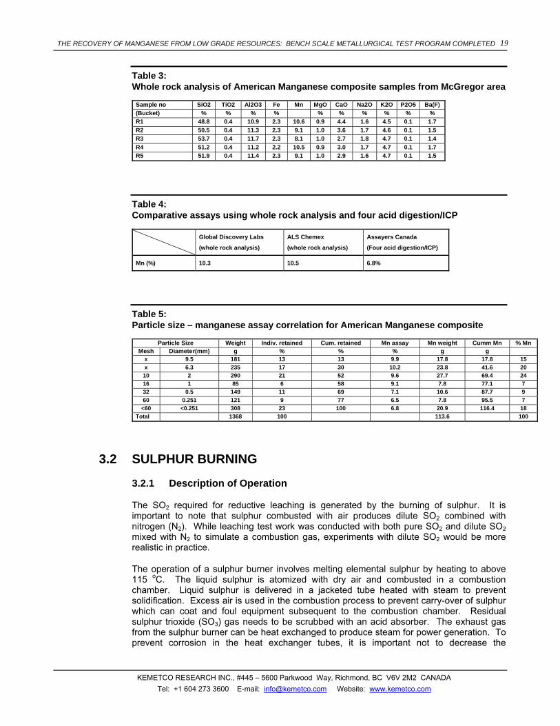
The hydrometallurgical work was performed on composite samples from the McGregor Pit area, American Manganese provided in 5 buckets. Each bucket was riffled and split to ensure homogeneity and representative samples were collected, pulverized and sent for whole rock analysis (lithium borate fusion followed by XRF) at ALS Chemex in North Vancouver, Canada. The manganese content varied between 8% and 10.6%, while the iron content was constant at 2.3%. A complete analysis of the samples is given in Table 3. Check assays were performed at ACME (Global Discovery Labs) and Assayers Canada in Vancouver, Canada, by whole rock analysis and four acid digestion / ICP, respectively (data provided in Table 4). The whole rock analysis method gave consistent results, with ALS Chemex yielding slightly higher results. The four acid digestion method reported significantly lower manganese grades, indicating incomplete digestion.
The ore sample with the highest manganese grade (bucket R4) was chosen for most of the subsequent hydrometallurgical scoping work.
Previous reports produced by Mountain States R&D International Inc. in Vail, Arizona, USA and PRA – Inspectorate, in Richmond, BC, Canada revealed that the ore is friable and mechanical agitation during slurrying produces significant amounts of fines that impede filtering and/or settling. The fine material, associated with clay and silt was believed contain little or no manganese, and removing the fine particles prior to leaching would lead to minor manganese losses. To investigate this hypothesis, a particle size analysis was performed on a representative sample weighing approx 1.5 kg removed from bucket R3. The various particle size fractions were then analyzed to determine whether manganese concentrates or not in the material with PS > 2 mm (10 mesh), as initially believed. The particle size analysis and the corresponding manganese assay for each of the particle size fractions are tabulated in Table 5. As seen in Table 5, the material with particle size larger than 2 mm contained more than 9.6% Mn, the manganese content dropping as the particle size decreased. However, even for the fraction with particle size below 60 mesh, the manganese content was still relatively high (6.5-6.8%) and the removal of the < 60 mesh fraction would mean losing about 18% of the total manganese content.
THE RECOVERY OF MANGANESE FROM LOW GRADE RESOURCES: BENCH SCALE METALLURGICAL TEST PROGRAM COMPLETED 19
KEMETCO RESEARCH INC., #445 – 5600 Parkwood Way, Richmond, BC V6V 2M2 CANADA Tel: +1 604 273 3600 E-mail: [email protected] Website: www.kemetco.com
Table 3: Whole rock analysis of American Manganese composite samples from McGregor area
Sample no SiO2 TiO2 Al2O3 Fe Mn MgO CaO Na2O K2O P2O5 Ba(F) (Bucket) % % % % % % % % % % R1 48.8 0.4 10.9 2.3 10.6 0.9 4.4 1.6 4.5 0.1 1.7 R2 50.5 0.4 11.3 2.3 9.1 1.0 3.6 1.7 4.6 0.1 1.5 R3 53.7 0.4 11.7 2.3 8.1 1.0 2.7 1.8 4.7 0.1 1.4 R4 51.2 0.4 11.2 2.2 10.5 0.9 3.0 1.7 4.7 0.1 1.7 R5 51.9 0.4 11.4 2.3 9.1 1.0 2.9 1.6 4.7 0.1 1.5
Table 4: Comparative assays using whole rock analysis and four acid digestion/ICP
Global Discovery Labs
(whole rock analysis)
ALS Chemex
(whole rock analysis)
Assayers Canada
(Four acid digestion/ICP)
Mn (%) 10.3 10.5 6.8%
Table 5: Particle size – manganese assay correlation for American Manganese composite
Particle Size Weight Indiv. retained Cum. retained Mn assay Mn weight Cumm Mn % Mn Mesh Diameter(mm) g % % % g g
x 9.5 181 13 13 9.9 17.8 17.8 15 x 6.3 235 17 30 10.2 23.8 41.6 20 10 2 290 21 52 9.6 27.7 69.4 24 16 1 85 6 58 9.1 7.8 77.1 7 32 0.5 149 11 69 7.1 10.6 87.7 9 60 0.251 121 9 77 6.5 7.8 95.5 7
<60 <0.251 308 23 100 6.8 20.9 116.4 18 Total 1368 100 113.6 100
3.2 SULPHUR BURNING
3.2.1 Description of Operation
The SO2 required for reductive leaching is generated by the burning of sulphur. It is important to note that sulphur combusted with air produces dilute SO2 combined with nitrogen (N2). While leaching test work was conducted with both pure SO2 and dilute SO2 mixed with N2 to simulate a combustion gas, experiments with dilute SO2 would be more realistic in practice.
The operation of a sulphur burner involves melting elemental sulphur by heating to above 115 oC. The liquid sulphur is atomized with dry air and combusted in a combustion chamber. Liquid sulphur is delivered in a jacketed tube heated with steam to prevent solidification. Excess air is used in the combustion process to prevent carry-over of sulphur which can coat and foul equipment subsequent to the combustion chamber. Residual sulphur trioxide (SO3) gas needs to be scrubbed with an acid absorber. The exhaust gas from the sulphur burner can be heat exchanged to produce steam for power generation. To prevent corrosion in the heat exchanger tubes, it is important not to decrease the

THE RECOVERY OF MANGANESE FROM LOW GRADE RESOURCES: BENCH SCALE METALLURGICAL TEST PROGRAM COMPLETED 20
KEMETCO RESEARCH INC., #445 – 5600 Parkwood Way, Richmond, BC V6V 2M2 CANADA Tel: +1 604 273 3600 E-mail: [email protected] Website: www.kemetco.com
temperature to below 150 oC. To provide a margin of safety, heat exchanging the exhaust gas to 400 oC would be a practical temperature.
3.2.2 Stoichiometry and Mass Balance
The combustion of sulphur with 20% excess air would proceed according to the following reaction:
S + 1.2O2 + 4.5N2 → SO2 + 0.2O2 + 4.5N2 (21)
According to Reaction 21, the molar ratio of the SO2 in the exhaust gas would be 17.5%.
With the basis of 140 metric tonnes per day of Mn production and assuming that 10% molar excess SO2 is used in the leach, approximately 91 metric tonnes per day of elemental sulphur will be required to feed the process.
3.2.3 Heat and Power Generation Calculations
In order to calculate the energy produced by the burning of sulphur, the thermodynamic data provided in Table 6 is required12.
Table 6: Thermodynamic Data for Sulphur Burning Calculations12
Heating Value of S (KJ/mole) 296.81
Cp [SO2 gas] (cal/mol⋅K) 7.70 + 0.00530T − 0.00000083T2
Cp [O2 gas] (cal/mol⋅K) 8.27 + 0.000258T - 187700/T2
Cp [N2 gas] (cal/mol⋅K) 6.50 + 0.00100T
The first step in determining the usable energy from the combustion of sulphur is to determine the adiabatic flame temperature. This is determined by balancing the heat generated by the full heating value of sulphur with the heat transferred to the exhaust gas (from an ambient temperature starting point).
The heat content in the exhaust gas can be calculated by integrating the specific heat with respect to temperature for each individual gas in the exhaust and multiplying by the molar amount of each gas. The formula for this calculation is as follows:
Heat in Exhaust = Σ ni ∫ Cp dT (22)
Where ni = number of moles of each gas in the exhaust
The integrated specific heats for each component of exhaust gas are provided in Table 7.
12 Perry’s Chemical Engineers Handbook, 8th Edition, Mcgraw-Hill, 2008, pp 1.237 – 1.298 & 2.156 – 2.163
THE RECOVERY OF MANGANESE FROM LOW GRADE RESOURCES: BENCH SCALE METALLURGICAL TEST PROGRAM COMPLETED 21
KEMETCO RESEARCH INC., #445 – 5600 Parkwood Way, Richmond, BC V6V 2M2 CANADA Tel: +1 604 273 3600 E-mail: [email protected] Website: www.kemetco.com
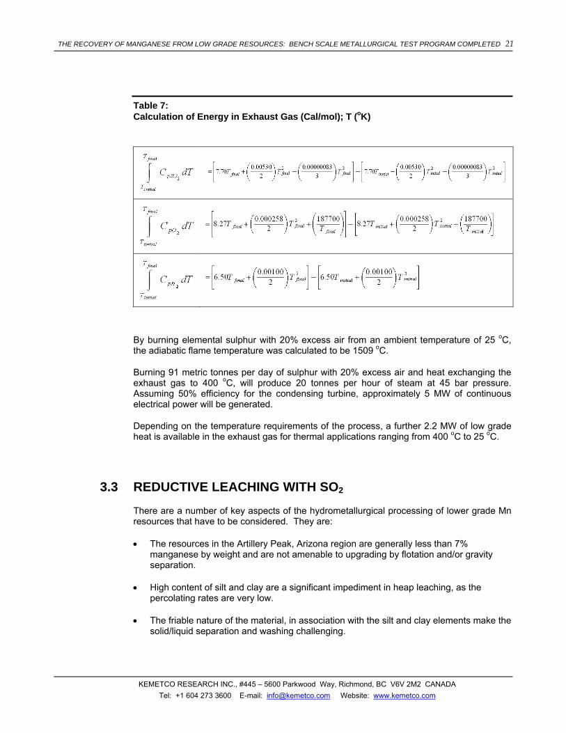
Table 7: Calculation of Energy in Exhaust Gas (Cal/mol); T (oK)
By burning elemental sulphur with 20% excess air from an ambient temperature of 25 oC, the adiabatic flame temperature was calculated to be 1509 oC.
Burning 91 metric tonnes per day of sulphur with 20% excess air and heat exchanging the exhaust gas to 400 oC, will produce 20 tonnes per hour of steam at 45 bar pressure. Assuming 50% efficiency for the condensing turbine, approximately 5 MW of continuous electrical power will be generated.
Depending on the temperature requirements of the process, a further 2.2 MW of low grade heat is available in the exhaust gas for thermal applications ranging from 400 oC to 25 oC.
3.3 REDUCTIVE LEACHING WITH SO2
There are a number of key aspects of the hydrometallurgical processing of lower grade Mn resources that have to be considered. They are:
• The resources in the Artillery Peak, Arizona region are generally less than 7% manganese by weight and are not amenable to upgrading by flotation and/or gravity separation.
• High content of silt and clay are a significant impediment in heap leaching, as the percolating rates are very low.
• The friable nature of the material, in association with the silt and clay elements make the solid/liquid separation and washing challenging.

THE RECOVERY OF MANGANESE FROM LOW GRADE RESOURCES: BENCH SCALE METALLURGICAL TEST PROGRAM COMPLETED 22
KEMETCO RESEARCH INC., #445 – 5600 Parkwood Way, Richmond, BC V6V 2M2 CANADA Tel: +1 604 273 3600 E-mail: [email protected] Website: www.kemetco.com
• To improve the settling properties and reduce the grinding cost, leaching of coarse particle size resource is desired.
• The presence of Mn4+ requires the use of a reducing agent such as SO2, to convert the insoluble Mn4+ to the soluble Mn2+ form.
• The manganese extraction with SO2 is associated with formation of dithionates.
• Achieving maximum manganese extraction into solution is desirable.
• Producing a pure manganese sulphate solution with Mn concentration above 40g/L is required to produce EMM.
• High acid consumption should be avoided.
The Artillery Peak mineralization consists of a mixture of manganese oxides, among which the most important are pyrolusite (MnO2), psilomelane ((BaH2O)2Mn5O10) and wad. As shown in the E-pH diagram for the manganese – water system (Figure 4), reducing Mn4+ and Mn3+ oxides to Mn2+ with a reducing agent such as SO2 dissolved in water would solubilise the Mn13.
13 Atlas of Electrochemical Equilibria in Aqueous Solutions, Marcel Pourbaix, Nace Publishing, 1974.
THE RECOVERY OF MANGANESE FROM LOW GRADE RESOURCES: BENCH SCALE METALLURGICAL TEST PROGRAM COMPLETED 23
KEMETCO RESEARCH INC., #445 – 5600 Parkwood Way, Richmond, BC V6V 2M2 CANADA Tel: +1 604 273 3600 E-mail: [email protected] Website: www.kemetco.com
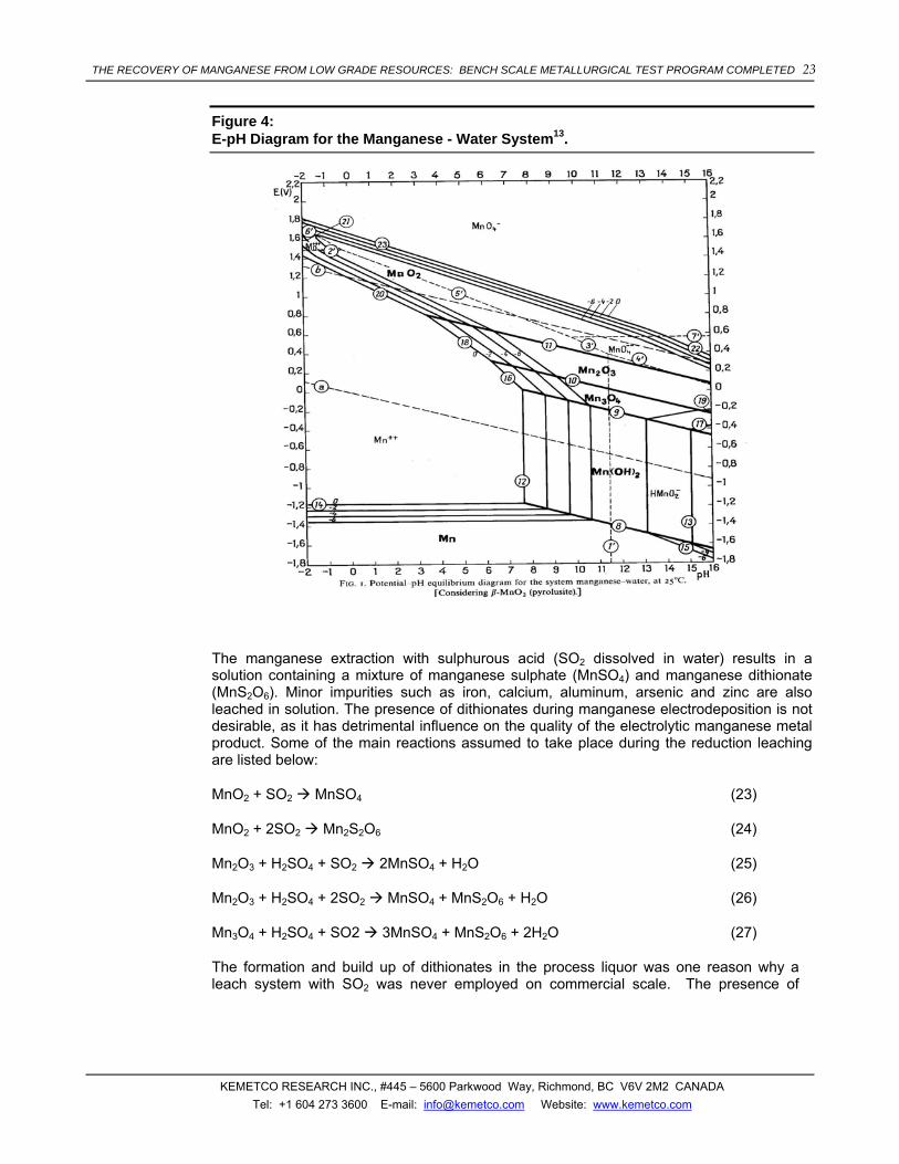
Figure 4: E-pH Diagram for the Manganese - Water System13.
The manganese extraction with sulphurous acid (SO2 dissolved in water) results in a solution containing a mixture of manganese sulphate (MnSO4) and manganese dithionate (MnS2O6). Minor impurities such as iron, calcium, aluminum, arsenic and zinc are also leached in solution. The presence of dithionates during manganese electrodeposition is not desirable, as it has detrimental influence on the quality of the electrolytic manganese metal product. Some of the main reactions assumed to take place during the reduction leaching are listed below:
MnO2 + SO2 MnSO4 (23)
MnO2 + 2SO2 Mn2S2O6 (24)
Mn2O3 + H2SO4 + SO2 2MnSO4 + H2O (25)
Mn2O3 + H2SO4 + 2SO2 MnSO4 + MnS2O6 + H2O (26)
Mn3O4 + H2SO4 + SO2 3MnSO4 + MnS2O6 + 2H2O (27)
The formation and build up of dithionates in the process liquor was one reason why a leach system with SO2 was never employed on commercial scale. The presence of
THE RECOVERY OF MANGANESE FROM LOW GRADE RESOURCES: BENCH SCALE METALLURGICAL TEST PROGRAM COMPLETED 24
KEMETCO RESEARCH INC., #445 – 5600 Parkwood Way, Richmond, BC V6V 2M2 CANADA Tel: +1 604 273 3600 E-mail: [email protected] Website: www.kemetco.com
dithionates during the deposition EMM or EMD was reported to lead to H2S release and can affect the quality and purity of the product14.
Preliminary tests performed with sulphuric acid alone yielded no manganese extraction, confirming that no M2+ species are present in the Artillery Peak resource.
3.3.1 Factors Influencing the Manganese Extraction and Dithionate Formation
Factors influencing leaching were studied utilizing a full factorial experimental design, with particle size, pulp density, SO2 concentration and H2SO4, as main factors and manganese extraction and dithionate concentration in the pregnant solution as responses. Stoichiometry was not considered an independent variable, as it depends on both SO2 concentration and pulp density and cannot be varied without changing one of the main factors
The effect of temperature was not investigated, however, the leaching reaction was observed to be exothermic. Although a decrease in temperature would be beneficial, both for the sulphur dioxide dissolution in water and for the manganese extraction, this option was not investigated.
For the purpose of the experimental design, a minimum, symbolized by (-) and maximum, symbolized by (+) were chosen for each of the effects investigated, as tabulated in Table 8. As seen in Table 8, the maximum pulp density used was about 27%, while the minimum was approx 10%. The tests were performed using particle (PS80) of 6 and respectively 70 mesh (3.36 mm and 210 µm), while the sulphuric acid concentration was 0.02 and 0.1M, respectively. The average manganese content of the 6 and 70 mesh samples were around 10.2% and 7.1%, respectively.
The sulphurous acid solutions were obtained by sparging pure SO2 gas from an SO2 gas cylinder in DI water, to achieve a stock solution with the maximum concentration of 6% by weight. The minimum SO2 concentration tested, 2.4% by weight, was obtained by diluting the stock solution with DI water.
The tests were performed in sealed bottles that were rolled to ensure continuous mixing of the slurry and samples were removed at various time intervals. The tests were terminated after 20 hours and the solid residues washed and sent out for analysis by fusion/XRD. The manganese concentration in solution analysis was analyzed by ICP. A direct method for dithionate analysis was developed in house, using Dionex 4500i ion chromatography with conductivity detector. The dithionate (S2O6
2-) was determined with a 4x50 mm Dionex AG4A-SC column and 2g/L Na2CO3 eluent at 1 mL/min, while the sulphates were determined with an AS4A column and a Na2CO3/NaHCO3 eluent at 2 mL/min. The initial SO2 concentration in aqueous solutions was determined by iodometric titrations
The experimental conditions, along with the resulting manganese extractions calculated based on the solid residue analysis by fusion/ XRF are provided in Table 8.
Increasing the particle size from 70 mesh to 6 mesh decreased only slightly the manganese extraction when using the maximum SO2 concentration of 6 wt%. The pulp density and the
14 Christopher Ward, “Hydrometallurgical Processing of Manganese Containing Materials”, PCT Patent Application
#WO 2004/033738 A1, HITECH ENERGY LIMITED, 2004.

THE RECOVERY OF MANGANESE FROM LOW GRADE RESOURCES: BENCH SCALE METALLURGICAL TEST PROGRAM COMPLETED 25
KEMETCO RESEARCH INC., #445 – 5600 Parkwood Way, Richmond, BC V6V 2M2 CANADA Tel: +1 604 273 3600 E-mail: [email protected] Website: www.kemetco.com
sulphurous acid concentration (stoichiometry) exhibited the largest effect on the final manganese extraction, both the kinetics and the manganese extractions were improved when working with 10% pulp density and 6 wt% SO2 solution. SO2 concentration became an important factor especially when working at high pulp density, as seen in Figure 5. Similarly, the sulphuric acid concentration had no effect at low pulp density, but became relevant high pulp density (Figure 6). Even more, manganese extraction of 98% was achieved at 10% pulp density and 6% SO2 , without any sulphuric acid addition. Low SO2 concentration correlated with large particle size had a detrimental effect on the manganese extractions, as well on the reaction kinetics.
The dithionate concentration was mainly influenced by pulp density and SO2 concentration, as the availability of both MnO2 and SO2 promoted the formation of dithionates. The presence of excess MnO2 did not decrease the dithionate concentration dramatically. As seen in Table 8, dithionate concentrations higher than 15g/L were observed even at [SO2]/[Mn] molar ratio of 0.54. Another factor influencing the dithionate concentration was the sulphuric acid concentration. Higher sulphuric acid concentrations contribute to the dithionate destruction. For example, bottle roll tests performed on 70 mesh samples, with 6% wt SO2, at 10% pulp density, yielded 12.7 g/L dithionate concentration when 0.1 M sulphuric acid was used, 25.3 g/L when 0.02M sulphuric acid was used and close to 30g/L when using no sulphuric acid.

THE RECOVERY OF MANGANESE FROM LOW GRADE RESOURCES: BENCH SCALE METALLURGICAL TEST PROGRAM COMPLETED 26
KEMETCO RESEARCH INC., #445 – 5600 Parkwood Way, Richmond, BC V6V 2M2 CANADA Tel: +1 604 273 3600 E-mail: [email protected] Website: www.kemetco.com
Figure 5: The Effect of Pulp Density (% wt) and SO2 conc. (%wt) on Mn extraction (%)
DESIGN-EXPERT Plot
Actual Mn extraction
Interaction Graph
Interaction of B:Pulp density and C:SO2 conc
Act
ual M
n ex
tract
ion
26
38.1667
50.3333
62.5
74.6667
86.8333
99
C-
C-
C+
C+
B- B+
Table 8: Experimental Design Test Conditions and Results
Run PS Pulp
density SO2 conc
H2SO4 conc PS
Pulp density
SO2 conc
H2SO4 conc [SO2]/[Mn]
pH Mn
Mn extr (20h)
S2O62- conc ( 20h)
mesh (wt%) (wt%) (M) mesh (wt%) (wt%) (M) g/L (%) (g/L) 1 6 10% 6 0.02 + - + - 4.54 1.4 11.0 96% 25.3 2 70 10% 6 0.1 - - + + 6.53 1.2 7.7 94% 18.7 3 6 27% 6 0.1 + + + + 1.34 1.6 36.7 95% 69.2 4 70 27% 2.4 0.1 - + - + 0.77 6.6 11.9 47% 30.2 5 6 27% 2.4 0.02 + + - - 0.54 6.6 8.6 26% 24.8 6 70 10% 2.4 0.02 - - - - 2.61 2.3 8.1 96% 21.9 7 70 27% 6 0.02 - + + - 1.93 6.4 17.5 57% 65.6 8 6 10% 2.4 0.1 + - - + 1.81 1.3 9.5 93% 17.5 9 70 10% 6 0.02 - - + - 6.53 1.1 8.2 97% 21.8 10 6 10% 2.4 0.02 + - - - 1.81 1.5 10.0 84% 19.1 11 70 27% 6 0.1 - + + + 1.93 1.1 25.3 97% 56.4 12 6 27% 6 0.02 + + + - 1.34 4.4 19.6 56% 47.7 13 70 27% 2.4 0.02 - + - - 0.77 5.7 9.9 33% 27.6 14 6 27% 2.4 0.1 + + - + 0.54 1.1 11.5 39% 16.4 15 6 10% 6 0.1 + - + + 4.54 0.8 9.3 88% 12.7 16 70 10% 2.4 0.1 - - - + 2.61 0.8 8.2 99% 19.8

THE RECOVERY OF MANGANESE FROM LOW GRADE RESOURCES: BENCH SCALE METALLURGICAL TEST PROGRAM COMPLETED 27
KEMETCO RESEARCH INC., #445 – 5600 Parkwood Way, Richmond, BC V6V 2M2 CANADA Tel: +1 604 273 3600 E-mail: [email protected] Website: www.kemetco.com
Figure 6: Effect of Pulp Density (%wt) and H2SO4 Concentration (M) on the Mn Extraction (%)
DESIGN-EXPERT Plot
Actual Mn extraction
Interaction Graph
Interaction of B:Pulp density and D:H2SO4 conc
Actua
l Mn
extra
ctio
n
26
38.1667
50.3333
62.5
74.6667
86.8333
99
D-
D-
D+
D+
B- B+

THE RECOVERY OF MANGANESE FROM LOW GRADE RESOURCES: BENCH SCALE METALLURGICAL TEST PROGRAM COMPLETED 28
KEMETCO RESEARCH INC., #445 – 5600 Parkwood Way, Richmond, BC V6V 2M2 CANADA Tel: +1 604 273 3600 E-mail: [email protected] Website: www.kemetco.com
Figure 7: Variation of Manganese Extraction as a Function of Pulp Density (% wt) and SO2 Concentration (% wt)
DESIGN-EXPERT Plot
Actual Factors:
X = SO2 conc
Y = Pulp density
Actual Constants:
Particle size = 1.78
H2SO4 conc = 0.06
Mn extraction
SO2 conc
Pul
p de
nsity
2.40 3.30 4.20 5.10 6.00
10.00
14.25
18.50
22.75
27.00
66.4487
74.3333
79.875
70.9599
58.5975
77.3732
83.1009
48.5342
91.8183
87.2911

THE RECOVERY OF MANGANESE FROM LOW GRADE RESOURCES: BENCH SCALE METALLURGICAL TEST PROGRAM COMPLETED 29
KEMETCO RESEARCH INC., #445 – 5600 Parkwood Way, Richmond, BC V6V 2M2 CANADA Tel: +1 604 273 3600 E-mail: [email protected] Website: www.kemetco.com
Figure 8: Variation of Mn Extraction as a Function of Particle Size (mm) and SO2 Concentration (% by weight)
DESIGN-EXPERT Plot
Actual Factors:
X = SO2 conc
Y = Particle size
Actual Constants:
Pulp density = 18.50
H2SO4 conc = 0.06
Mn extraction
SO2 conc
Par
ticle
siz
e
2.40 3.30 4.20 5.10 6.00
0.21
1.00
1.78
2.57
3.36
66.4487
74.3333 79.87570.9599
77.3732 83.1009
62.0796

THE RECOVERY OF MANGANESE FROM LOW GRADE RESOURCES: BENCH SCALE METALLURGICAL TEST PROGRAM COMPLETED 30
KEMETCO RESEARCH INC., #445 – 5600 Parkwood Way, Richmond, BC V6V 2M2 CANADA Tel: +1 604 273 3600 E-mail: [email protected] Website: www.kemetco.com
Figure 9: Variation of Dithionate Concentration (g/L) as a Function of SO2 Concentration (% wt) and Pulp Density (%wt)
DESIGN-EXPERT Plot
Actual Factors:
X = Pulp density
Y = SO2 conc
Actual Constants:
Particle size = 1.78
H2SO4 conc = 0.06
Dithionate conc
Pulp density
SO
2 co
nc
10.00 14.25 18.50 22.75 27.00
2.40
3.30
4.20
5.10
6.00
22.783326.8542
30.925
34.9958
39.8506
20.0925
49.1106
3.3.2 Stirred Tank Counter Current Leaching with Concentrated SO2
The concept of counter current leaching as a method of destroying the dithionates was investigated by performing a 3 stage scoping test. The first stage leach test was performed in magnetically stirred reactor at 10% pulp density, on the manganese ore with PS < 100µm. The lixiviant contained 0.05M sulphuric acid and approx 6% SO2. After two hours, the slurry was filtered and the filtrate was used in the 2nd stage to leach a fresh ore sample. Similarly, the pregnant solution from the 2nd stage was used to leach a fresh ore sample in the 3rd stage. The tailings from each of the three tests were washed and sent for analysis.
The test conditions and the results are tabulated in Table 9. As the first stage was performed with excess SO2, complete manganese extraction was attained in the first two hours. In the second stage, the residual SO2 was consumed by the fresh ore, increasing the manganese concentration from 11g/L at the end of the first stage, to 16 g/L at the end of the second stage. No additional manganese was extracted during the third stage and even significant MnO2 excess did not result in dithionate destruction. Probably due to the neutral pH, the residual sulphites reacted with the pyrolusite to produce additional dithionates.
However, besides facilitating complete SO2 consumption, the counter current leaching also allows the economical utilization of the ore alkalinity to purify the pregnant solution. As seen in Table 9, at the end of the first stage, some of the main impurities were Fe (269 ppm), Al (102 ppm) and As (42 ppm). The increase in pH from 1.2 to 2 lead to a significant reduction in all three impurities, while at pH 6.3 the pregnant solution contained less than 1 ppm Fe, Al and As.

THE RECOVERY OF MANGANESE FROM LOW GRADE RESOURCES: BENCH SCALE METALLURGICAL TEST PROGRAM COMPLETED 31
KEMETCO RESEARCH INC., #445 – 5600 Parkwood Way, Richmond, BC V6V 2M2 CANADA Tel: +1 604 273 3600 E-mail: [email protected] Website: www.kemetco.com
Table 9: Counter Current Leaching – Conditions and Results
Sample Time Sample vol Volume Wt solids pHf Free SO2% S2O62- Mn Net Mn Fe Al Ca Cu K Zn As Mn Mn extr Fe Fe extr
(min) mL mL (g) g/L ppm ppm ppm ppm ppm ppm ppm ppm ppm (g) (%) (g) (%)
1st stage 100
1 5 10 900 6% 11174 244 60.9 1941 5.30 252 34.3 40.6 10.06 98% 0.22 10%
2 10 10 890 11347 253 66.7 1698 5.33 243 31.1 42.8 10.21 99% 0.23 10%
3 20 10 880 11307 258 70.9 1559 5.39 235 31.0 44.6 10.17 99% 0.23 10%
4 30 10 870 11277 258 72.1 1469 5.44 233 30.9 41.8 10.15 99% 0.22 10%
5 60 10 860 11172 261 77.3 1514 5.29 233 30.9 43.0 10.06 98% 0.22 10%
6 120 10 850 1.2 1.3% 22 11413 269 102 1724 5.55 249 31.9 42.0 10.26 100% 0.23 11%
2nd stage 83
1 5 10 745 12455 1042 198 42.0 1562 6.02 231 39.6 42.3 0.78 9%
2 10 10 735 14176 2764 95.5 42.3 1246 5.70 238 40.2 38.7 2.04 24%
3 20 10 725 14667 3254 87.6 38.7 1225 4.60 221 40.5 33.7 2.40 28%
4 30 10 715 15008 3595 67.8 33.7 1289 3.98 214 40.9 32.0 2.64 30%
5 60 10 705 16317 4905 15.4 32.0 1239 1.85 218 40.6 17.7 3.53 41%
6 120 10 695 2.0 0.3% 26 16825 5413 4.18 17.7 1250 1.37 223 40.0 9.79 3.92 45%
3rd stage 70
6 120 10 595 6.3 - 33 16206 <1. <1. 1479 <1. 248 21 <1.
3.3.3 Stirred Tank with Dilute SO2
Following a meeting with Noram Engineering and Constructors Ltd. of Vancouver, Canada, we were advised to perform additional leaching work using a gas mixture containing 14-16 vol% SO2 and 84-86% N2, as producing SO2 by burning sulphur is practical only when using air as the oxidant. As a result, a series of additional stirred tank tests on ore samples of various particle sizes were performed with a SO2/N2 mixture, using the experimental set-up presented in Figure 10. The pulp density and sulphuric acid concentrations were maintained at 10% and 0.05M, respectively and the mixing of the slurry was achieved using a magnetic stirrer. The mixture of SO2 (50 mL /min) and N2 (270 mL/min) was sparged directly into the slurry. The excess SO2 was scrubbed in 3M NaOH solution, and the extraction tests were considered terminated when the SO2 concentration in the scrub solution reached approx 1g/L. The manganese extraction dropped from 94% when leaching samples characterized by PS <100 mesh (<0.15 mm), to approx 73% when the PS increased to 6 mesh (3.36 mm). The manganese extraction was reduced to as low as 55% at particle sizes as large as 3 mesh (6.7 mm). Because the ore is friable and breaks down during agitation, longer retention times yielded better manganese extractions. However, the magnetic agitation was not strong enough to reduce the particle size enough for complete manganese extraction.

THE RECOVERY OF MANGANESE FROM LOW GRADE RESOURCES: BENCH SCALE METALLURGICAL TEST PROGRAM COMPLETED 32
KEMETCO RESEARCH INC., #445 – 5600 Parkwood Way, Richmond, BC V6V 2M2 CANADA Tel: +1 604 273 3600 E-mail: [email protected] Website: www.kemetco.com
Figure 10: Experimental Set-up for Manganese Extraction with SO2/N2 Mixture
The stirred tank tests performed so far, confirmed that leaching of coarse samples, with dilute SO2 gas is technically viable and milling prior to the leaching stage is not obligatory. Nevertheless, complete manganese extractions can only be achieved slowly, as the material breaks down to particle size below 70 mesh.
A subsequent test was performed at 40% pulp density, on a coarse sample containing more than 35wt% particles larger than 9.5 mm. To accelerate the manganese extraction, the slurry agitation was attained using an overhead mixer (Figure 11). The manganese extraction increased with the decrease in the particle size, from 17% after 1 hour, to 90% after 12 hours.
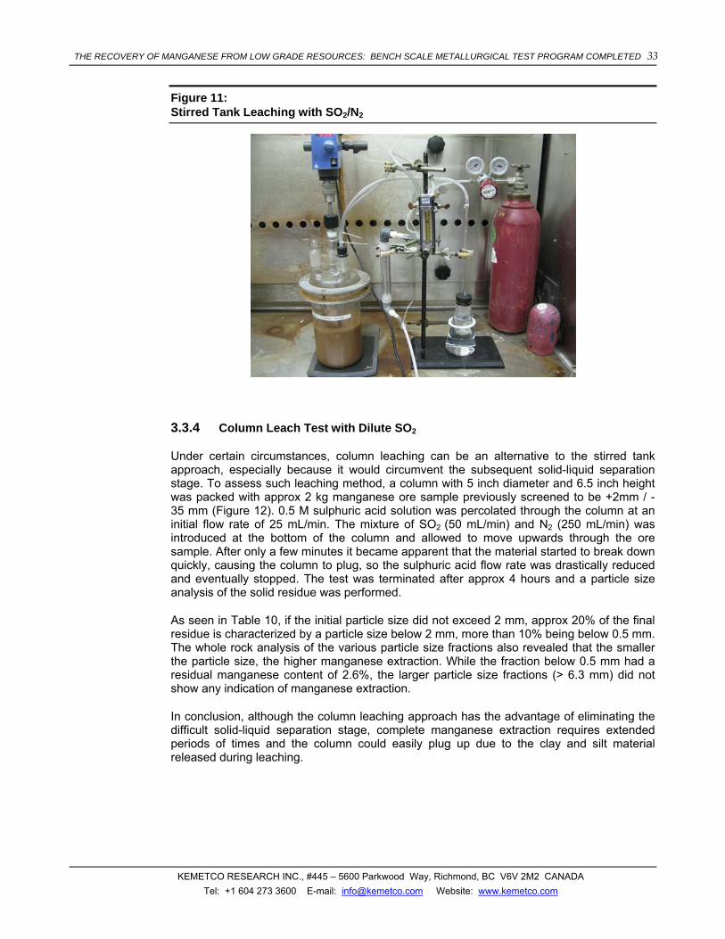
THE RECOVERY OF MANGANESE FROM LOW GRADE RESOURCES: BENCH SCALE METALLURGICAL TEST PROGRAM COMPLETED 33
KEMETCO RESEARCH INC., #445 – 5600 Parkwood Way, Richmond, BC V6V 2M2 CANADA Tel: +1 604 273 3600 E-mail: [email protected] Website: www.kemetco.com
Figure 11: Stirred Tank Leaching with SO2/N2
3.3.4 Column Leach Test with Dilute SO2
Under certain circumstances, column leaching can be an alternative to the stirred tank approach, especially because it would circumvent the subsequent solid-liquid separation stage. To assess such leaching method, a column with 5 inch diameter and 6.5 inch height was packed with approx 2 kg manganese ore sample previously screened to be +2mm / - 35 mm (Figure 12). 0.5 M sulphuric acid solution was percolated through the column at an initial flow rate of 25 mL/min. The mixture of SO2 (50 mL/min) and N2 (250 mL/min) was introduced at the bottom of the column and allowed to move upwards through the ore sample. After only a few minutes it became apparent that the material started to break down quickly, causing the column to plug, so the sulphuric acid flow rate was drastically reduced and eventually stopped. The test was terminated after approx 4 hours and a particle size analysis of the solid residue was performed.
As seen in Table 10, if the initial particle size did not exceed 2 mm, approx 20% of the final residue is characterized by a particle size below 2 mm, more than 10% being below 0.5 mm. The whole rock analysis of the various particle size fractions also revealed that the smaller the particle size, the higher manganese extraction. While the fraction below 0.5 mm had a residual manganese content of 2.6%, the larger particle size fractions (> 6.3 mm) did not show any indication of manganese extraction.
In conclusion, although the column leaching approach has the advantage of eliminating the difficult solid-liquid separation stage, complete manganese extraction requires extended periods of times and the column could easily plug up due to the clay and silt material released during leaching.

THE RECOVERY OF MANGANESE FROM LOW GRADE RESOURCES: BENCH SCALE METALLURGICAL TEST PROGRAM COMPLETED 34
KEMETCO RESEARCH INC., #445 – 5600 Parkwood Way, Richmond, BC V6V 2M2 CANADA Tel: +1 604 273 3600 E-mail: [email protected] Website: www.kemetco.com
Figure 12: Column Leach Set-up
Table 10: Ore Sample Characterization Before and After Column Leaching Test
Feed material Solid residue Mesh Diameter Wt Retained Mn Wt Retained Mn
mm g % % g % % x 9.5 500.23 24.99 9.9% 467.8 24.38 10.2% x 6.3 660.95 33.02 10.2% 456.63 23.80 10.6%
10 2 840.51 41.99 9.6% 540.41 28.17 8.7% 16 1 104.34 5.44 5.3% 32 0.5 104.77 5.46 4.2%
<32 <0.5 244.76 12.76 2.6% Total 2001.69 100.00 1918.71 100.00
3.4 SOLID LIQUID SEPARATION
As a part of flowsheet development for manganese recovery, a series of settling tests were conducted using fresh leach solutions under a range of possible operating conditions. The objective of this work was to evaluate the effects of common flocculants and to provide sufficient settling data to allow confidence in sizing of thickeners for solid-liquid separation.

THE RECOVERY OF MANGANESE FROM LOW GRADE RESOURCES: BENCH SCALE METALLURGICAL TEST PROGRAM COMPLETED 35
KEMETCO RESEARCH INC., #445 – 5600 Parkwood Way, Richmond, BC V6V 2M2 CANADA Tel: +1 604 273 3600 E-mail: [email protected] Website: www.kemetco.com
3.4.1 Flocculant Screening
On-going optimization of the process stages prior to settling has identified several possible operating conditions for feed particle size and pulp density. To ensure that there is sufficient settling data to cover the range of likely operating conditions, a test matrix was established to evaluate different types and levels of flocculant addition using both coarse and fine feed, and using low and high pulp density in the leach.
The test matrix is shown below:
Table 11: Settling test matrix
Pulp Density
10% solids 20% solids
Grind Size
No floc
Percol 351
Percol E24
No floc Percol 351
Percol E24
6# x 5 ppm 5 ppm x 10 ppm 10 ppm
6# 10 ppm 10 ppm 30 ppm 30 ppm
70# x 10 ppm 10 ppm x 30 ppm 30 ppm
In addition to the above 16 tests, one test was added with 70# feed leached at 30% solids. This test used Percol 351 at 10 ppm as a flocculant. A further test involved decanting the leach solution after one of the above tests (6# feed leached at 10% solids and settled with 5 ppm Percol 351) and re-pulping the settled solids with de-ionized water to conduct another settling test without further flocculant addition. This latter test was to simulate a counter current washing stage in the process circuit.
Each test consisted of production of test feed by carrying out a 1 litre leach using the specified pulp density and size of feed material, followed by transfer of the entire leach pulp to a 1 litre graduated cylinder for settling measurement. If required, flocculant in the specified dosage was added as a pre-mixed 1 g/L solution. The initial slurry level was marked and the covered cylinder was inverted several times to ensure complete mixing, and to give flocs an opportunity to form. The cylinder was the set down and a timer started. As soon as a solid-liquid interface was evident, the level was recorded at short time intervals until settling slowed to the compression phase. The level was then checked and recorded again intermittently over 2-4 hours, and a final level was recorded after 24 hours.
Tests allowed comparison of settling of un-flocculated slurry with different flocculants. While there are many types of flocculant available, keeping the test matrix to a reasonable size required narrowing the choice to a small number of likely options. For this testing one anionic (Percol E24) and one non-ionic (Percol 351) flocculant were chosen. Both are very commonly used in industry, and Percol 351 is known to be used by other manganese operations. The dosages used cover a typical range for low pulp-density slurries.
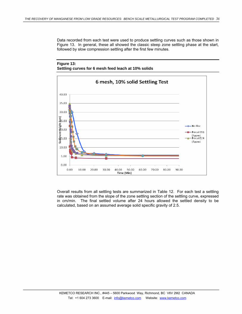
THE RECOVERY OF MANGANESE FROM LOW GRADE RESOURCES: BENCH SCALE METALLURGICAL TEST PROGRAM COMPLETED 36
KEMETCO RESEARCH INC., #445 – 5600 Parkwood Way, Richmond, BC V6V 2M2 CANADA Tel: +1 604 273 3600 E-mail: [email protected] Website: www.kemetco.com
Data recorded from each test were used to produce settling curves such as those shown in Figure 13. In general, these all showed the classic steep zone settling phase at the start, followed by slow compression settling after the first few minutes.
Figure 13: Settling curves for 6 mesh feed leach at 10% solids
Overall results from all settling tests are summarized in Table 12. For each test a settling rate was obtained from the slope of the zone settling section of the settling curve, expressed in cm/min. The final settled volume after 24 hours allowed the settled density to be calculated, based on an assumed average solid specific gravity of 2.5.

THE RECOVERY OF MANGANESE FROM LOW GRADE RESOURCES: BENCH SCALE METALLURGICAL TEST PROGRAM COMPLETED 37
KEMETCO RESEARCH INC., #445 – 5600 Parkwood Way, Richmond, BC V6V 2M2 CANADA Tel: +1 604 273 3600 E-mail: [email protected] Website: www.kemetco.com
Table 12: Compiled settling test results
Test # Feed Density Dose (ppm)
Floc Settling Rate
(cm/min)
Final Volume
(ml)
Settled Density
(% solids)
1 6# 10% None 3.05 140 50.0
4 70# 10% None 1.42 180 41.7
9 6# 20% None 1.37 290 48.8
12 70# 20% None 0.47 350 42.6
2-wash 6# wash 10% None 9.66 150 47.6
3 6# 10% 2 ppm Percol 351 15.17 155 46.5
2 6# 10% 5 ppm Percol 351 73.44 107 59.9
5 70# 10% 5 ppm Percol 351 6.65 190 40.0
10 6# 20% 5 ppm Percol 351 18.29 270 51.3
11 6# 20% 10 ppm Percol 351 6.44 280 50.0
13 70# 20% 10 ppm Percol 351 0.63 330 44.4
17 70# 30% 10 ppm Percol 351 2.40 365 55.0
7 6# 10% 2 ppm Percol E24 5.04 150 47.6
6 6# 10% 5 ppm Percol E24 20.64 150 47.6
8 70# 10% 5 ppm Percol E24 2.23 190 40.0
14 6# 20% 5 ppm Percol E24 9.57 240 55.6
15 6# 20% 10 ppm Percol E24 15.05 250 54.1
16 70# 20% 10 ppm Percol E24 0.68 325 44.9
For comparison purposes, settling rates and final densities were plotted for each flocculant tested, as shown in Figures 14 to 16. Both flocculants provided significant improvements over settling without flocculation in all cases, with the difference being especially dramatic at lower pulp densities.
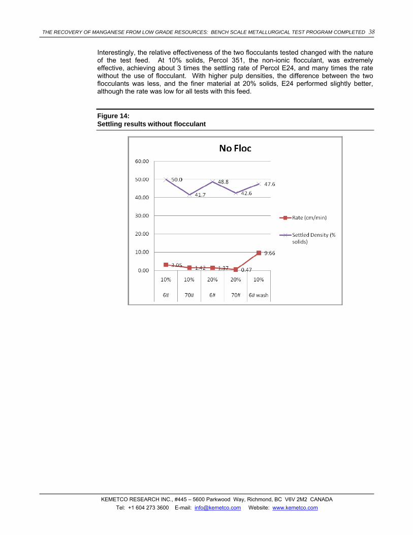
THE RECOVERY OF MANGANESE FROM LOW GRADE RESOURCES: BENCH SCALE METALLURGICAL TEST PROGRAM COMPLETED 38
KEMETCO RESEARCH INC., #445 – 5600 Parkwood Way, Richmond, BC V6V 2M2 CANADA Tel: +1 604 273 3600 E-mail: [email protected] Website: www.kemetco.com
Interestingly, the relative effectiveness of the two flocculants tested changed with the nature of the test feed. At 10% solids, Percol 351, the non-ionic flocculant, was extremely effective, achieving about 3 times the settling rate of Percol E24, and many times the rate without the use of flocculant. With higher pulp densities, the difference between the two flocculants was less, and the finer material at 20% solids, E24 performed slightly better, although the rate was low for all tests with this feed.
Figure 14: Settling results without flocculant

THE RECOVERY OF MANGANESE FROM LOW GRADE RESOURCES: BENCH SCALE METALLURGICAL TEST PROGRAM COMPLETED 39
KEMETCO RESEARCH INC., #445 – 5600 Parkwood Way, Richmond, BC V6V 2M2 CANADA Tel: +1 604 273 3600 E-mail: [email protected] Website: www.kemetco.com
Figure 15: Settling results with Percol 351

THE RECOVERY OF MANGANESE FROM LOW GRADE RESOURCES: BENCH SCALE METALLURGICAL TEST PROGRAM COMPLETED 40
KEMETCO RESEARCH INC., #445 – 5600 Parkwood Way, Richmond, BC V6V 2M2 CANADA Tel: +1 604 273 3600 E-mail: [email protected] Website: www.kemetco.com
Figure 16: Settling results with Percol E24
Percol E24 also gave higher final densities than E351 with the higher initial pulp density. Also, at the higher pulp density, E351 appeared to work best at a lower dose, losing effectiveness when the dosage was doubled. E24 however, showed significantly improved results at higher strength.
In conclusion, some very effecting flocculation/settling results were obtained when using low pulp densities. Higher densities, which are more likely to be required for effective process operation, also show significantly improved settling with proper flocculant addition, but this has probably not yet been optimized.
The quantity of fines present is also a very important parameter, and if processing will result in substantial fines generation, then further optimization of settling would also need to focus on fines. When the operating conditions for the leaching have been more defined, additional settling work can be focused on those conditions to minimize the solid-liquid separation equipment requirements.
The best result to date, 73 cm/min at 10% solids using a lower dose of Percol E351 non-ionic focculant. While additional work is required to improve settling rates at higher pulp densities, preliminary design work will focus around the best operating conditions, which consists of lower pulp density and the use of a non-ionic focculant.

THE RECOVERY OF MANGANESE FROM LOW GRADE RESOURCES: BENCH SCALE METALLURGICAL TEST PROGRAM COMPLETED 41
KEMETCO RESEARCH INC., #445 – 5600 Parkwood Way, Richmond, BC V6V 2M2 CANADA Tel: +1 604 273 3600 E-mail: [email protected] Website: www.kemetco.com
3.4.2 Preliminary Leached Ore Thickener and CCD Sizing
Counter current decantation (CCD) thickener circuits are used to recover soluble values in pregnant liquor from leached slurries. The basis of CCD operation is to concentrate suspended solids thereby minimizing liquor content in underflow slurry that flow in one direction. Then the underflow slurry liquor is diluted with wash liquor that flows in the opposite direction and the suspended solids are concentrated again.
The amount of liquor in the thickener underflow contributes to determining the number of CCD stages required to recover the desired amount of soluble metal.
Preliminary testwork was performed on leached ore in order to define approximate size of leached ore in CCD circuit thickeners.
The settling testwork included series of bench scale settling tests to identify correlation between flocculant dose applied and feed slurry dilution with free settling rate which then was used as a Conventional Thickener sizing criteria by Coe and Clevenger method. Another settling test was carried out to define correlation of underflow density with the compaction time (24 h).
Due to the shortage of fresh leached sample, samples of one month and older were re-pulped with liquor and then used for settling test work in order to identify flocculant dose and optimal dilution conditions. Once such conditions are identified and sufficient amount of fresh leached material accumulated confirmation tests should be carried out to ensure “sample ageing” factor is eliminated.
Solids density was defined as 2320 kg/m3, and liquor density used was 1075 kg/m3, which was obtained by dilution of 50 g/l of Mn, 1150 kg/m3 liquor with DI water 1:1. All settling tests were carried out at ambient temperature and pH of the slurry was adjusted to 1.
1L glass cylinders were used to measure solids settling rates after flocculant was applied to the slurry of various densities.
Curves representing settling rates at different flocculant doses and slurry dilutions are shown in Figure 17.

THE RECOVERY OF MANGANESE FROM LOW GRADE RESOURCES: BENCH SCALE METALLURGICAL TEST PROGRAM COMPLETED 42
KEMETCO RESEARCH INC., #445 – 5600 Parkwood Way, Richmond, BC V6V 2M2 CANADA Tel: +1 604 273 3600 E-mail: [email protected] Website: www.kemetco.com
Figure 17: Settling Rates for Different Flocculant Dose and Pulp Density
16% and 12% pulp density
0.5 0.6
2.22
7.92
2.0
5.88
9.96
0.0
2.0
4.0
6.0
8.0
10.0
12.0
0.0 50.0 100.0 150.0 200.0 250.0 300.0 350.0
Flocc dose, g/t
Setlt
ing
rate
, m/h
16% 12%
Settling rates of 24% slurry were also measured at various flocculant doses but they are not shown on the graph because they were very low (less then few mm per min) and far out of practical range.
Practically usable settling rates are found at a solids concentration of less than 16 % wt and flocculant application rate of 150-200 gram of E351 (Ciba) per tone of solids. Flocculant dose applied to the slurry seems to be high and flocculant screening series of settling test are needed to identify more efficient type.
Together with settling rates turbidity of supernatant solution was measured and results are given in Figure 18.

THE RECOVERY OF MANGANESE FROM LOW GRADE RESOURCES: BENCH SCALE METALLURGICAL TEST PROGRAM COMPLETED 43
KEMETCO RESEARCH INC., #445 – 5600 Parkwood Way, Richmond, BC V6V 2M2 CANADA Tel: +1 604 273 3600 E-mail: [email protected] Website: www.kemetco.com
Figure 18: Turbidity of Supernatant
Overflow turbidity vs Flocculant dose (E351)
0.0
10.0
20.0
30.0
40.0
50.0
60.0
70.0
0.0 100.0 200.0 300.0Flocc dose, g/t
Turb
idity
, NTU
16% 12%
Compaction test for 30% slurry (24 hrs) carried out in 2L cylinder (flocculation rate – 150 g/t) showed that solids density which can be reached within 24 hour settling is about 45% of solids without raking which can slightly increase density of compacted solids, however in the practice conventional thickeners’ residence time is normally no longer than 4 hours which corresponds to 38% of solids content in underflow in this particular case. Compaction curve is given on Figure 19.
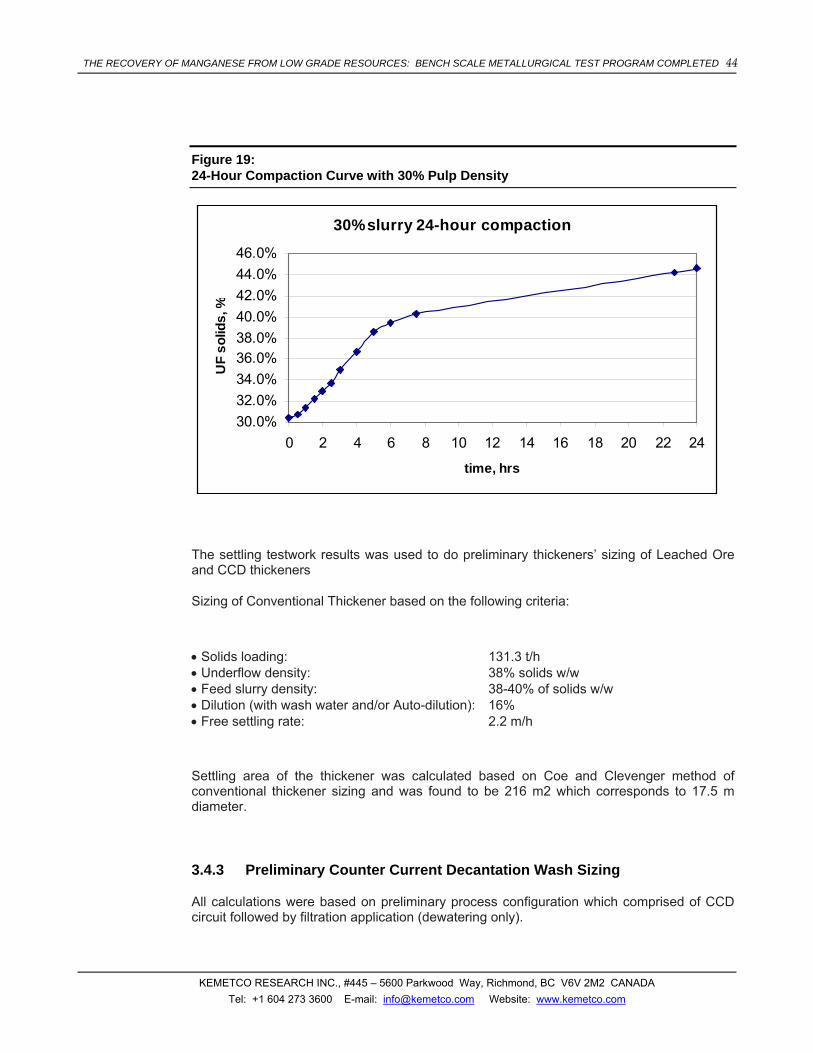
THE RECOVERY OF MANGANESE FROM LOW GRADE RESOURCES: BENCH SCALE METALLURGICAL TEST PROGRAM COMPLETED 44
KEMETCO RESEARCH INC., #445 – 5600 Parkwood Way, Richmond, BC V6V 2M2 CANADA Tel: +1 604 273 3600 E-mail: [email protected] Website: www.kemetco.com
Figure 19: 24-Hour Compaction Curve with 30% Pulp Density
30% slurry 24-hour compaction
30.0%32.0%34.0%36.0%38.0%40.0%42.0%44.0%46.0%
0 2 4 6 8 10 12 14 16 18 20 22 24
time, hrs
UF
solid
s, %
The settling testwork results was used to do preliminary thickeners’ sizing of Leached Ore and CCD thickeners
Sizing of Conventional Thickener based on the following criteria:
• Solids loading: 131.3 t/h • Underflow density: 38% solids w/w • Feed slurry density: 38-40% of solids w/w • Dilution (with wash water and/or Auto-dilution): 16% • Free settling rate: 2.2 m/h
Settling area of the thickener was calculated based on Coe and Clevenger method of conventional thickener sizing and was found to be 216 m2 which corresponds to 17.5 m diameter.
3.4.3 Preliminary Counter Current Decantation Wash Sizing
All calculations were based on preliminary process configuration which comprised of CCD circuit followed by filtration application (dewatering only).

THE RECOVERY OF MANGANESE FROM LOW GRADE RESOURCES: BENCH SCALE METALLURGICAL TEST PROGRAM COMPLETED 45
KEMETCO RESEARCH INC., #445 – 5600 Parkwood Way, Richmond, BC V6V 2M2 CANADA Tel: +1 604 273 3600 E-mail: [email protected] Website: www.kemetco.com
Preliminary evaluated mass balance showed that 5 stage CCD thickener circuit with 2.3 washing ratio (ratio of feed slurry entrained liquid volume to wash liquid volume) washing efficiency sufficient to reach targeted level of overall Mn extraction of 99.5% for 38% solids slurry with 50 g/l Mn content in entrained solution even without taking into account Mn contained in a filtrate recycled from filtration stage.
Figure 20: CCD Wash Efficiency
CCD Washing EfficiencyWash ratio - 2.3
0
99.12%97.08%92.41%
56.91%
81.65%
0%10%20%30%40%50%60%70%80%90%
100%
0 1 2 3 4 5 6
No of stages
Effic
ienc
y, %
2.3 wash ratio is the maximum feasible that can be reached in case of feed slurry dilution to 16% and corresponds to 0% of thickener overflow recycle (auto-dilution).
Further flowsheet optimization to be done after filtration testwork is carried out and filter cake humidity identified. Lower wash rate would be needed in order to reach the same level of Mn extraction and dilution of feed slurry would be a combination of wash liquid flow and thickener overflow recycling (auto-dilution). For example at filter cake humidity of 15% w/w only 1.6 wash ratio is required for 5-stage CCD circuit or 1.9 for 4-stage CCD.
Suggested process configuration and equipment sizing are not optimized yet and should be revised by equipment manufacturing company based on detailed testwork to be carried out.
As some other options it might be total replacement of CCD circuit by horizontal belt filter application with several washing stages or fewer number of stages CCD circuit followed by vacuum belt filter with one or two washing stages
Use of High Density or Paste thickeners is another option that can give higher solids content in underflow and resulting in less number of CCD stages and/or lower washing ratio, but feasibility of using this type of equipment and questions of handling higher underflow density should be evaluated by solid-liquid separation equipment supplier.

THE RECOVERY OF MANGANESE FROM LOW GRADE RESOURCES: BENCH SCALE METALLURGICAL TEST PROGRAM COMPLETED 46
KEMETCO RESEARCH INC., #445 – 5600 Parkwood Way, Richmond, BC V6V 2M2 CANADA Tel: +1 604 273 3600 E-mail: [email protected] Website: www.kemetco.com
3.4.4 Toxicity Characteristic Leaching Procedure on Tailings
The Toxicity Characteristic Leaching Procedure (TCLP) is EPA Test Method 1311, which is used to simulate leaching through a landfill. This test method is used to determine if a material is classified as a hazardous waste.
TCLP testing was conducted on two solid tailings produced from the testwork on the American Manganese resource. Sample #100608-1 consists of leach residue that was treated with lime to reach a neutral pH. Sample #100608-2 consists of leach residue that was only rinsed and dried before TCLP testing. The results of the TCLP tests are provided in Table 13. The results show that in both cases the American Manganese tailings passed the TCLP tests and are not considered hazardous waste as defined by The Code of Federal Regulations. Table 14 outlines the maximum concentration of contaminants required for non-hazardous classification15.
Table 13: TCLP Test Results on American Manganese Leach Residue
TCLP METALS (SOLID)Maxxam ID U65605 U65606Sampling DateCOC Number 537548 537548
Units 100608-1 100608-2 RDL QC BatchMetalsLEACHATE Antimony (Sb) mg/L <0.1 <0.1 0.1 4019505LEACHATE Arsenic (As) mg/L 0.4 <0.1 0.1 4019505LEACHATE Barium (Ba) mg/L 0.2 0.3 0.1 4019505LEACHATE Beryllium (Be) mg/L <0.1 <0.1 0.1 4019505LEACHATE Boron (B) mg/L <0.1 <0.1 0.1 4019505LEACHATE Cadmium (Cd) mg/L <0.1 <0.1 0.1 4019505LEACHATE Chromium (Cr) mg/L <0.1 <0.1 0.1 4019505LEACHATE Cobalt (Co) mg/L <0.1 <0.1 0.1 4019505LEACHATE Copper (Cu) mg/L 0.3 <0.1 0.1 4019505LEACHATE Iron (Fe) mg/L <0.5 <0.5 0.5 4019505LEACHATE Lead (Pb) mg/L <0.1 <0.1 0.1 4019505LEACHATE Mercury (Hg) mg/L <0.002 <0.002 0.002 4019505LEACHATE Molybdenum (Mo) mg/L 0.4 <0.1 0.1 4019505LEACHATE Nickel (Ni) mg/L <0.1 <0.1 0.1 4019505LEACHATE Selenium (Se) mg/L <0.1 <0.1 0.1 4019505LEACHATE Silver (Ag) mg/L <0.1 <0.1 0.1 4019505LEACHATE Thallium (Tl) mg/L 0.9 0.2 0.1 4019505LEACHATE Uranium (U) mg/L <0.1 <0.1 0.1 4019505LEACHATE Vanadium (V) mg/L <0.1 <0.1 0.1 4019505LEACHATE Zinc (Zn) mg/L 0.1 <0.1 0.1 4019505LEACHATE Zirconium (Zr) mg/L <0.1 <0.1 0.1 4019505
RDL = Reportable Detection Limit
15 Code of Federal Regulations, http://ecfr.gpoaccess.gov

THE RECOVERY OF MANGANESE FROM LOW GRADE RESOURCES: BENCH SCALE METALLURGICAL TEST PROGRAM COMPLETED 47
KEMETCO RESEARCH INC., #445 – 5600 Parkwood Way, Richmond, BC V6V 2M2 CANADA Tel: +1 604 273 3600 E-mail: [email protected] Website: www.kemetco.com
Table 14: Maximum Concentration of Contaminants for the Toxicity Characteristic
3.5 PREGNANT LEACHATE PURIFICATION
As manganese has a high negative value in the electromotive series, the levels of other metals with high reduction potential should be controlled very tightly. As an example, for manganese metal electrodeposition, the impurity content in the solution feed is limited to <0.5 ppm Co, <10 ppm Fe, <1 ppm Ni and <5 ppm Cu, <1000 ppm Al.
As discussed in the manganese extraction section, the main impurities present in the manganese pregnant solution are iron, aluminum, arsenic and silica. Small amounts of zinc, cobalt and copper are also present, their levels depending on the pulp density and the

THE RECOVERY OF MANGANESE FROM LOW GRADE RESOURCES: BENCH SCALE METALLURGICAL TEST PROGRAM COMPLETED 48
KEMETCO RESEARCH INC., #445 – 5600 Parkwood Way, Richmond, BC V6V 2M2 CANADA Tel: +1 604 273 3600 E-mail: [email protected] Website: www.kemetco.com
concentration of sulphuric acid used. Typical impurities levels in pregnant solutions obtained at various pulp densities and pH below 1 are given in Table 15.
Increasing the pH to above 5.5, reduced the levels of aluminum, arsenic, iron to below 1 ppm and significantly diminished the silica and copper levels. The pH adjustment had little impact on zinc and cobalt.
Table 15: Typical impurities in pregnant manganese solutions
PLS 1 PLS 2 PLS3
Pulp density during Mn extr 10% 27% 40%
H2SO4 conc 0.05M 0.05M 0.5M
Element ppm ppm ppm Al Aluminium 102 224 689 As Arsenic 42.0 47.3 166 Ca Calcium 1724 1082 558 Cd Cadmium 1.11 <0.1 <0.1 Co Cobalt 1.16 2.84 10.2 Cu Copper 5.55 12.0 21.1 Fe Iron 269 453 1307 K Potassium 249 345 1119 Mg Magnesium 99.7 261 520 Mn Manganese 11413 23443 58467 Mo Molybdenum <1. <1. <1. Na Sodium 587 1551 2805 Ni Nickel <0.5 <0.5 <0.5 Pb Lead <2. <2. <2. Si Silicon 90.2 212 106 Sn Tin <2. <2. <2. Zn Zinc 31.9 66.4 1511
Removal of copper, zinc and cobalt is usually done by selectively precipitating them as sulphides, as shown in the reaction below. (NH4)2S, NaHS, Na2S or even H2S can all be used as sources of sulphide; in our experiments NaHS was utilized.
Zn2+ + S2- ZnS (28)
An example of pregnant manganese solution composition before and after purification is given in Table 16. Sulphide precipitation of zinc and cobalt is best done at neutral pH. Excess S2- should be avoided, as residual sulphides could report to the electrolytic manganese metal during the electrolysis.

THE RECOVERY OF MANGANESE FROM LOW GRADE RESOURCES: BENCH SCALE METALLURGICAL TEST PROGRAM COMPLETED 49
KEMETCO RESEARCH INC., #445 – 5600 Parkwood Way, Richmond, BC V6V 2M2 CANADA Tel: +1 604 273 3600 E-mail: [email protected] Website: www.kemetco.com
Table 16: Manganese purification example
PLS pH ~ 1
PLS pH ~ 5.6
PLS after NaHS
treatment pH ~ 5.6
Al Aluminium 291 6.30 2.52 As Arsenic 35.63 <2. <2. Ca Calcium 893 831 880 Cd Cadmium <0.1 <0.1 <0.1 Co Cobalt 1.98 1.75 <0.5 Cu Copper 9.56 <1. <1. Fe Iron 354 1.19 <1. K Potassium 329 341 334 Mg Magnesium 264 1754 1739 Mn Manganese 17006 16690 16600 Mo Molybdenum <1. <1. <1. Na Sodium 1303 1321 1396 Ni Nickel <0.5 <0.5 <0.5 Pb Lead <2. <2. <2. Si Silicon 146 16.04 13.11 Sn Tin <2. <2. <2. Zn Zinc 53.19 23.05 <0.5
3.6 MANGANESE CARBONATE PRECIPITATION
Precipitation of the MnCO3 proceeds according to the following reactions:
MnSO4 + Na2CO3 → MnCO3 + Na2SO4 (29)
MnS2O6 + Na2CO3 → MnCO3 + Na2S2O6 (30)
Pregnant leach solution used for the MnCO3 precipitation test was prepared by leaching the Artillery Peak resource with SO2 in a stirred tank reactor, 40% pulp density by weight and 6 hours. The pregnant leach solution was treated to remove impurities by raising the pH to 6 with sodium hydroxide and air sparging to precipitate Al, As and Fe. After filtering the solids, the filtrate was then treated with a stoichiometric amount of NaHS to precipitate Zn, which was then removed by filtration. 20 litres of the pregnant leach solution of approximately 50 g/L was prepared in this manner.
Manganese precipitation was carried out by addition of 150 g/L Na2CO3 slurry, at a stoichiometric ratio of 0.8 carbonate to manganese, to the pregnant leach solution in a stirred tank reactor. Precipitation of MnCO3 occurred instantaneously after the addition of Na2CO3 to the pregnant leach solution (Figure 21). After complete precipitation (Figure 22), the MnCO3 precipitate was filtered from the solution by vacuum filtration in a Buchner funnel (Figure 23) to collect a wet cake. The wet cake was re-pulped and washed and filtered again to produce a clean wet cake of MnCO3 (Figure 24). The wet cake was dried in a low temperature oven at 30 oC to produce dry MnCO3 (Figure 25).
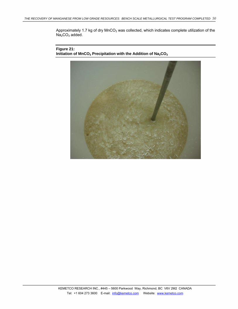
THE RECOVERY OF MANGANESE FROM LOW GRADE RESOURCES: BENCH SCALE METALLURGICAL TEST PROGRAM COMPLETED 50
KEMETCO RESEARCH INC., #445 – 5600 Parkwood Way, Richmond, BC V6V 2M2 CANADA Tel: +1 604 273 3600 E-mail: [email protected] Website: www.kemetco.com
Approximately 1.7 kg of dry MnCO3 was collected, which indicates complete utilization of the Na2CO3 added.
Figure 21: Initiation of MnCO3 Precipitation with the Addition of Na2CO3

THE RECOVERY OF MANGANESE FROM LOW GRADE RESOURCES: BENCH SCALE METALLURGICAL TEST PROGRAM COMPLETED 51
KEMETCO RESEARCH INC., #445 – 5600 Parkwood Way, Richmond, BC V6V 2M2 CANADA Tel: +1 604 273 3600 E-mail: [email protected] Website: www.kemetco.com
Figure 22: Complete Precipitation of MnCO3

THE RECOVERY OF MANGANESE FROM LOW GRADE RESOURCES: BENCH SCALE METALLURGICAL TEST PROGRAM COMPLETED 52
KEMETCO RESEARCH INC., #445 – 5600 Parkwood Way, Richmond, BC V6V 2M2 CANADA Tel: +1 604 273 3600 E-mail: [email protected] Website: www.kemetco.com
Figure 23: Filtration of the MnCO3 Precipitate
Figure 24: Wet Cake of MnCO3

THE RECOVERY OF MANGANESE FROM LOW GRADE RESOURCES: BENCH SCALE METALLURGICAL TEST PROGRAM COMPLETED 53
KEMETCO RESEARCH INC., #445 – 5600 Parkwood Way, Richmond, BC V6V 2M2 CANADA Tel: +1 604 273 3600 E-mail: [email protected] Website: www.kemetco.com
Figure 25: Dry Solids of MnCO3
3.7 WATER RECOVERY, ANHYDROUS SODIUM SULPHATE PRODUCTION AND DITHIONATE DESTRUCTION
Most of the water used in the overall process finds its way to the Na2SO4 and Na2S2O6 containing solution that is produced after precipitation of MnCO3. Water is recovered with very high energy efficiency by cooling this solution to crystallize Na2SO4⋅10H2O and Na2S2O6⋅2H2O. The mother liquor from the cooling crystallizer will have a significantly reduced concentration of Na2SO4 and Na2S2O6 and as such can be processed through a nanofiltration system to produce clean water, which can be recycled in the overall process, and a concentrate that can be returned to the crystallizer to remove Na2SO4 and Na2S2O6.
This process is a significantly more energy efficient method of separating water from the salt compared to evaporation, since it avoids the energy intensive latent heat of vaporization. Recovery of water in this manner is made possible because of the unusual solubility characteristics of Na2SO4. As shown in Figure 2616, the solubility of Na2SO4 decrease more than ten-fold when decreasing temperature from 32 to 0 oC, forming a decahydrate. By
16 W.F. Linke, A. Seidell, “Solubilities of Inorganic and Metal Organic Compounds”, 4th ed., Van Nostrand, 1965.

THE RECOVERY OF MANGANESE FROM LOW GRADE RESOURCES: BENCH SCALE METALLURGICAL TEST PROGRAM COMPLETED 54
KEMETCO RESEARCH INC., #445 – 5600 Parkwood Way, Richmond, BC V6V 2M2 CANADA Tel: +1 604 273 3600 E-mail: [email protected] Website: www.kemetco.com
fortuity, as shown in Figure 27, the solubility of Na2S2O6 decreases almost three-fold when decreasing temperature from 30 to 0 oC, forming a dihydrate17.
The majority of water is recovered from the hydrated crystals by heating the crystals to above 32 oC. At this temperature, Na2SO4⋅10H2O dehydrates to form anhydrous Na2SO4, H2O and Na2S2O6.2H2O. After solid-liquid separation, the H2O can be sent through the nanofiltration system to produce more clean water. In is important to note that aside from the presence of Na2S2O6, this is substantially the same method that is used extensively to process Na2SO4 in commercial practice.
Figure 26: Solubility of Sodium Sulphate versus Temperature
17 W.C. de Baat, “Sur L’Acid Dithionique et Ses Sels”, Recueil des Travaux Chimiques des Pays-Bas, vol 45, 1926,
pp 237.

THE RECOVERY OF MANGANESE FROM LOW GRADE RESOURCES: BENCH SCALE METALLURGICAL TEST PROGRAM COMPLETED 55
KEMETCO RESEARCH INC., #445 – 5600 Parkwood Way, Richmond, BC V6V 2M2 CANADA Tel: +1 604 273 3600 E-mail: [email protected] Website: www.kemetco.com
Figure 27: Solubility of Sodium Dithionate versus Temperature
Solubility of Sodium Dithionate vs Temperature
0
2
4
6
8
10
12
14
16
18
20
0 10 20 30 40 50 60 70 80 90 100
Temperature (deg C)
Gra
ms
Na2
S2O
6 pe
r 100
g W
ater
3.7.1 Preliminary Mass Balance
A complete preliminary mass balance was conducted on the process that relates to water recovery, anhydrous sodium sulphate generation and dithionate destruction. This mass balance is provided in Table 17.

THE RECOVERY OF MANGANESE FROM LOW GRADE RESOURCES: BENCH SCALE METALLURGICAL TEST PROGRAM COMPLETED 56
KEMETCO RESEARCH INC., #445 – 5600 Parkwood Way, Richmond, BC V6V 2M2 CANADA Tel: +1 604 273 3600 E-mail: [email protected] Website: www.kemetco.com
Table 17: Preliminary Mass Balance for Water Recovery, Anhydrous Na2SO4 Production and Destruction of Dithionates
Mn ProductionWeight of Ore Processed (Metric Tonnes per day) 3500Mn Grade (%) 4.50%Recovery (%) 90%Mn Production (Metric Tonnes per day) 141.75
LeachingMolar Excess SO2 Used in Leach (%) 10%Concentration of PLS (g Mn per kg solution) 50Weight of MnSO4 Produced (Metric Tonnes per day) 350.7Weight of MnS2O6 Produced (Metric Tonnes per day) 55.5Weight of Water in PLS (Metric Tonnes per day) 2428.9
Manganese Carbonate PrecipitationWeight of Na2CO3 Required (Metric Tonnes per day) 273.5Weight of MnCO3 Produced (Metric Tonnes per day) 296.6Weight of Na2SO4 in By-Product Solution (Metric Tonnes per day) 329.8Weight of Na2S2O6 in By-Product Solution (Metric Tonnes per day) 53.2Weight of Water in By-Product Solution (Metric Tonnes per day) 2428.9
Cooling CrystallizerSolubility of Na2SO4 at 0 deg C (g/kg water) 11Solubility of Na2S2O6 at 0 deg C (g/kg water) 60Weight of Water from Nanofiltration Recycle (Metric Tonnes per day) 1319.8Weight of Water from Carbonate Precipitation (Metric Tonnes per day) 2428.9Total Weight of Water Input to Cooler (Metric Tonnes per day) 3748.6Weight of Na2SO4 Input to Cooler (Metric Tonnes per day) 371.0Weight of Na2S2O6 Input to Cooler (Metric Tonnes per day) 277.5Weight of Na2SO4.10H20 Output Crystals (Metric Tonnes per day) 748.2Weight of Na2S2O6.2H2O Output Crystals (Metric Tonnes per day) 62.5Weight of Water in Mother Solution (Metric Tonnes per day) 3321.0Weight of Na2SO4 in Mother Solution (Metric Tonnes per day) 41.1Weight of Na2S2O6 in Mother Solution (Metric Tonnes per day) 224.4
DehydrationWater Recovery from Dehydration of Na2SO4.10H2O (Metric Tonnes per day) 418.3
NanofiltrationWeight of Water Input (Metric Tonnes per day) 3739.3Clean Water Output (Metric Tonnes per day) 2419.6Weight of Water in Concentrate Recycle (Metric Tonnes per day) 1319.8Concentration of Na2SO4 Input (g/kg water) 11.0Concentration of Na2S2O6 Input (g/kg water) 60.0Concentration of Na2SO4 in Concentrate (g/kg water) 31.2Concentration of Na2S2O6 in Concentrate (g/kg water) 170.0Nanofiltration Efficiency 64.7%
CalcinationNa2SO4 Input (Metric Tonnes per day) 329.8Na2S2O6.2H2O Input (Metric Tonnes per day) 62.5SO2 Output (Metric Tonnes per day) 16.5H2O Output (Metric Tonnes per day) 9.3Na2SO4 Output (Metric Tonnes per day) 366.5
Water Recovery% Water Recovery of Process 100.0%

THE RECOVERY OF MANGANESE FROM LOW GRADE RESOURCES: BENCH SCALE METALLURGICAL TEST PROGRAM COMPLETED 57
KEMETCO RESEARCH INC., #445 – 5600 Parkwood Way, Richmond, BC V6V 2M2 CANADA Tel: +1 604 273 3600 E-mail: [email protected] Website: www.kemetco.com
3.7.2 Calculated Preliminary Energy Balance
In order to conduct a preliminary energy balance for water recovery, anhydrous sodium sulphate production and destruction of dithionates to recover SO2, the data summarized in Table 18 is required.
Table 18: Thermodynamic Data Required for Energy Balance Calculations
THERMODYNAMIC DATA REFERENCE
Latent Heat of Vaporization (H2O) = 2260 KJ/kg 12
Cp (H2O liquid) = 4.186 (KJ/kg oC) 12
Cp (Na2SO4⋅10H2O) = 499.3 (J/mol oC) 12
Cp (Na2SO4) = 128.2 (J/mol oC) 12
Cp (Na2S2O6⋅2H2O) = Data Not Available, Estimate as Na2SO4⋅10H2O
∆H (Na2SO4⋅10H2O) = -4327.26 (KJ/mol) 12
∆H (Na2SO4) = -1387.1 (KJ/mol) 12
∆H (H2O liquid) = -285.83 (KJ/mol) 12
∆H (Na2S2O6⋅2H2O) = Data Not Available, Estimate as ∆H (MnS2O6⋅2H2O)
∆H (MnS2O6⋅2H2O) = -1991.2 (KJ/mol) 18
∆H (MnSO4) = -1065.3 (KJ/mol) 12
∆H (SO2) = -296.81 (KJ/mol) 12
∆H (H2O gas) = -241.86 (KJ/mol) 12
The energy requirements to operate reverse osmosis for desalination was estimated at 2 KWh per m3 of water processed19 (used to estimate energy consumption for nanofiltration).
According to Tammann20 et al Na2S2O6⋅2H2O decomposes at 267 oC, evolving SO2 gas.
18 Feng Guozhong Lei Yidong, “The Measurements of Thermodynamic Functions of Manganese Dithionate
Hydrates”, Journal of Guangxi University (Natural Science Edition), Vol. 2, 1992
19 P. Geisler, W. Krumm , and T.A. Peters, “Reduction of the energy demand for seawater RO with the pressure exchange system PES”, Desalination, Vol. 135, 2001, pp. 205-210.

THE RECOVERY OF MANGANESE FROM LOW GRADE RESOURCES: BENCH SCALE METALLURGICAL TEST PROGRAM COMPLETED 58
KEMETCO RESEARCH INC., #445 – 5600 Parkwood Way, Richmond, BC V6V 2M2 CANADA Tel: +1 604 273 3600 E-mail: [email protected] Website: www.kemetco.com
Using a design basis of 141.75 metric tonnes per day of Mn production and a pregnant leachate concentration of 50 g Mn per kg water, the following energy balance was calculated by Kemetco (Table 19).
Table 19: Calculated Preliminary Power Requirements to Recover Water, Process Anhydrous Sodium Sulphate and Decompose Dithionates
American Manganese Water Recovery and Dithionate Destruction Process MW
Power to Chill Na2SO4 + Na2S2O6 Solution from 25 oC to 0 oC and Crystallize Na2SO4⋅H2O and Na2S2O6⋅2H2O
7.77
Power to Heat Crystals from 0 oC to 40 oC 0.60
Power for Nanofiltration 0.25
Power to Calcine Na2SO4 and Na2S2O6⋅2H2O Crystals to 267 oC 1.55
Heat Recovery from Mother Liquid at 0 oC -4.34
Low Grade Heat Recovery from Sulphur Burner Exhaust for Calcine -0.81
Low Grade Heat Recovery from Sulphur Burner Exhaust for Heating Crystals -0.60
Total Power with American Manganese Process 4.42
3.7.3 Preliminary Energy Balance Using Data Provided by a Commercial Supplier of Sodium Sulphate Production Plants
Swenson Technology Inc is a commercial supplier of sodium sulphate crystallizer systems. Swenson was provided operating conditions for treatment of the Na2SO4 and Na2S2O6 solution stream in the American Manganese process. Based on this information, Swenson provided a preliminary flowsheet, shown in Figure 28, with preliminary process power requirements.
Using the data provided by Swenson’s flowsheet, process power requirements were calculated and summarized in Table 20.
20 Von G. Tammann, W. Boehme, “Zur Zersetzung der Dithionate”, Zeitschrift Für Anorganische und Allgemeine
Chemie, Vol. 204, 1932, pp 144.

THE RECOVERY OF MANGANESE FROM LOW GRADE RESOURCES: BENCH SCALE METALLURGICAL TEST PROGRAM COMPLETED 59
KEMETCO RESEARCH INC., #445 – 5600 Parkwood Way, Richmond, BC V6V 2M2 CANADA Tel: +1 604 273 3600 E-mail: [email protected] Website: www.kemetco.com
Table 20: Calculated Preliminary Energy Balance to Recover Water, Process Anhydrous Sodium Sulphate and Decompose Dithionates Using Data from Swenson
American Manganese Water Recovery and Dithionate Destruction Process
HP mmBTU/hr MW
Power to Chill Na2SO4 + Na2S2O6 Solution from 25 oC to 0 oC and Crystallize Na2SO4⋅H2O and Na2S2O6⋅2H2O
1500 1.10
Power to Heat Crystals from 0 oC to 40 oC 7.5 2.20
Power for Nanofiltration 1200 0.88
Power to Calcine Na2SO4 and Na2S2O6⋅2H2O Crystals to 267 oC (Not Provided by Swenson, used data in Table 19)
1.55
Low Grade Heat Recovery from Sulphur Burner Exhaust for Calcine (Not Provided by Swenson, used data in Table 19)
-0.81
Low Grade Heat Recovery from Sulphur Burner Exhaust for Heating Crystals (Not Provided by Swenson, used data in Table 19)
-1.30
Total Power with American Manganese Process 3.62

THE RECOVERY OF MANGANESE FROM LOW GRADE RESOURCES: BENCH SCALE METALLURGICAL TEST PROGRAM COMPLETED 60
KEMETCO RESEARCH INC., #445 – 5600 Parkwood Way, Richmond, BC V6V 2M2 CANADA Tel: +1 604 273 3600 E-mail: [email protected] Website: www.kemetco.com
Figure 28: Preliminary Flowsheet for Recovery of Water, Production of Anhydrous Sodium Sulphate, and Destruction of Dithionates (data from Swenson Technology Inc.)

THE RECOVERY OF MANGANESE FROM LOW GRADE RESOURCES: BENCH SCALE METALLURGICAL TEST PROGRAM COMPLETED 61
KEMETCO RESEARCH INC., #445 – 5600 Parkwood Way, Richmond, BC V6V 2M2 CANADA Tel: +1 604 273 3600 E-mail: [email protected] Website: www.kemetco.com
3.7.4 Comparing Energy Balance with Data from a Commercial Sodium Sulphate Plant
In order to compare the calculated energy balance to recover water, produce anhydrous sodium sulphate and decompose dithionates, detailed operating data for a commercial sodium sulphate production plant was obtained. The commercial sodium sulphate production plant is operated by Laguna del Rey, in Mexico and a flowsheet of the operation is provided in Figure 2921.
Figure 29: Flowsheet for the Laguna del Rey Sodium Sulphate Plant
Operating data for the Laguna del Rey sodium sulphate plant is summarized and compared to the calculated operating conditions of the American Manganese plant (see Table 21). Similarities between the calculated installed power per unit production of Na2SO4 supports the technical and economical viability of this approach for the American Manganese process.
21 Donald E. Garrett, “Sodium Sulfate, Handbook of Deposits, Processing, Properties, and Use”, Academic Press,
2001, pp 220 – 225.

THE RECOVERY OF MANGANESE FROM LOW GRADE RESOURCES: BENCH SCALE METALLURGICAL TEST PROGRAM COMPLETED 62
KEMETCO RESEARCH INC., #445 – 5600 Parkwood Way, Richmond, BC V6V 2M2 CANADA Tel: +1 604 273 3600 E-mail: [email protected] Website: www.kemetco.com
Table 21: Comparison of Operating Conditions between the Laguna del Rey Sodium Sulphate Plant and the Proposed American Manganese Plant.
Laguna del Rey, Mexico21
(Operating)
American Manganese Inc
(Proposed)
Anhydrous Na2SO4 Production Metric Tonnes Per Year 620,000 133,773
Concentration of Na2SO4 (g/L) 200 150
Volume Flow Rate (L/min) 6800 1687
Installed Power (MW) 14 3.62 - 4.42
Calculated Energy Consumption (KWh/Tonne Na2SO4) 198 237 - 290
3.7.5 Comparing Energy Balance with Simple Evaporation
In order to show the dramatic difference in process power required to recover water using the American Manganese process versus simple evaporation, an energy balance between both approaches are summarized in Table 22. The calculations are based on 141.75 metric tonnes per day Mn production and a pregnant leachate concentration of 50 g/L.

THE RECOVERY OF MANGANESE FROM LOW GRADE RESOURCES: BENCH SCALE METALLURGICAL TEST PROGRAM COMPLETED 63
KEMETCO RESEARCH INC., #445 – 5600 Parkwood Way, Richmond, BC V6V 2M2 CANADA Tel: +1 604 273 3600 E-mail: [email protected] Website: www.kemetco.com
Table 22: Comparison of Power Usage to Recover Water by Simple Evaporation versus the American Manganese Process.
Power Requirements for Simple Evaporation MW
Specific Heat to Raise Temperature From 25 oC to 100 oC 8.83
Latent Heat Requirements for Simple Evaporation 63.53
Low Grade Heat Recovery from Sulphur Burner Exhaust to 100 oC -1.79
Total Power with Simple Evaporation 70.57
American Manganese Water Recovery and Dithionate Destruction Process MW
Power to Chill Na2SO4 + Na2S2O6 Solution from 25 oC to 0 oC and Crystallize Na2SO4⋅10H2O and Na2S2O6⋅2H2O
7.77
Power to Heat Crystals from 0 oC to 40 oC 0.60
Power for Nanofiltration 0.25
Power to Calcine Na2SO4 and Na2S2O6⋅2H2O Crystals to 267 oC 1.55
Heat Recovery from Mother Liquid at 0 oC -4.34
Low Grade Heat Recovery from Sulphur Burner Exhaust for Calcine -0.81
Low Grade Heat Recovery from Sulphur Burner Exhaust for Heating Crystals -0.60
Total Power with American Manganese Process 4.42
Table 22 shows that the energy required to recover water from the process stream containing Na2SO4 and Na2S2O6 in the American Manganese conceptual process is approximately 6% of that required if done so by conventional evaporation techniques. The latent heat of vaporization accounts for the majority of the power requirement for evaporation. The use of mechanical vapour recompression (MVR) evaporation technology can recover some of the latent heat by recompressing the vapour phase so that heat can be recovered by heat exchange. MVR evaporation can also significantly reduce power consumption in evaporation since a significant amount of the latent loss can be recovered. Prior to considering MVR evaporation, extensive corrosion studies should be conducted, since MVR units are expensive equipment. Evolution of SO2 gas mixed with water would create a corrosive environment within the MVR components.
THE RECOVERY OF MANGANESE FROM LOW GRADE RESOURCES: BENCH SCALE METALLURGICAL TEST PROGRAM COMPLETED 64
KEMETCO RESEARCH INC., #445 – 5600 Parkwood Way, Richmond, BC V6V 2M2 CANADA Tel: +1 604 273 3600 E-mail: [email protected] Website: www.kemetco.com
3.7.6 Dithionate Thermal Decomposition Testwork
In order to better investigate the conditions required to effectively destroy dithionates using MnO2 and isolate other interferences, a scoping test using reagent grade chemicals was performed. For this test, a solution containing 20g/L sodium dithionate was contacted with excess MnO2 for 24 hours. The dithionate concentration remained constant when no sulphuric acid was added, but dropped to 18.7g/L and 17.2 g/L in the presence of 0.8M and 1.6M H2SO4, respectively. This suggests that dithionates can be decreased by excess MnO2 and acid, although the high requirement of sulphuric acid makes the approach less attractive from an economic point of view.
Thermal decomposition proved to be a successful strategy to eliminate the dithionates. The first thermal decomposition test was performed on a pregnant solution produced during a bottle test. In a first stage, the water was evaporated at around 105o, producing a salt containing about 5.6% dithionates. The resulting salt was then placed in an oven and the temperature was slowly increased and maintained at 400oC for 30 minutes. Salt samples were removed at 200oC and 400oC and the dithionates were analyzed by ion chromatography. The dithionates analysis revealed that more than 80% dithionates were removed at 200oC, while complete decomposition was achieved at 400oC.
The goal of the second test was to determine the lowest temperature required for complete dithionate decomposition. 50 mL pregnant solution from a bottle roll test containing approximately 48g/L dithionates was placed overnight in an oven, at 75oC, to evaporate the water. The resulting salt, containing 10.2% dithionates, was then slowly heated to 400oC in 50oC increments. Solid samples were removed at 150, 200, 250, 300 and 400oC and the dithionates were analyzed by IC. Surprisingly, complete destruction of dithionates was observed at 250oC, a much lower temperature than previously reported by Hazen Research (1977). In fact, the dithionate content was reduced by approx 80% by drying alone. The thermal decomposition approach has the advantage of allowing the recovery and recirculation of sulphur dioxide that otherwise would be lost.
3.7.7 Use of a Bioreactor to Reduce Dithionates
An alternative process scheme that uses a proprietary bioreactor to destroy dithionates, and recover SO2, energy and sodium bicarbonate (NaHCO3) was tested. While mass and energy balances have not been conducted during this preliminary work, testing of the bioreactor has shown that biological reduction of Na2S2O6 can be achieved at a significantly higher rate than biological reduction of Na2SO4.
As a proof of concept, a gas-fed continuous laboratory reactor was set-up (Figure 30) and operated. Sulphite reducing bacteria population was transferred from an existing bio-reactor developed by Kemetco and a 15g/L dithionate solution with trace micro-nutrients (KH2PO4, MgSO4, (NH4)2SO4, CaCl2, NaCl and FeSO4) was pumped through as a feed solution. Gaseous feed such as CO, CO2 and H2 were also added. The net reaction in the bioreactor is as follows:
Na2S2O6 + 2CO + 5H2 → 2H2S + 2NaHCO3 + 2H2O (31)
In concept, the H2S generated by the bioreactor can be burned to produce energy and recover SO2 to be recycled back to the leach. The NaHCO3 bioreactor product can be used to precipitate Mn for recovery from the pregnant leach solution.
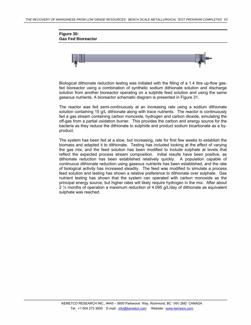
THE RECOVERY OF MANGANESE FROM LOW GRADE RESOURCES: BENCH SCALE METALLURGICAL TEST PROGRAM COMPLETED 65
KEMETCO RESEARCH INC., #445 – 5600 Parkwood Way, Richmond, BC V6V 2M2 CANADA Tel: +1 604 273 3600 E-mail: [email protected] Website: www.kemetco.com
Figure 30: Gas Fed Bioreactor
Biological dithionate reduction testing was initiated with the filling of a 1.4 litre up-flow gas-fed bioreactor using a combination of synthetic sodium dithionate solution and discharge solution from another bioreactor operating on a sulphite feed solution and using the same gaseous nutrients. A bioreactor schematic diagram is presented in Figure 31.
The reactor was fed semi-continuously at an increasing rate using a sodium dithionate solution containing 15 g/L dithionate along with trace nutrients. The reactor is continuously fed a gas stream containing carbon monoxide, hydrogen and carbon dioxide, simulating the off-gas from a partial oxidation burner. This provides the carbon and energy source for the bacteria as they reduce the dithionate to sulphide and product sodium bicarbonate as a by-product.
The system has been fed at a slow, but increasing, rate for first few weeks to establish the biomass and adapted it to dithionate. Testing has included looking at the effect of varying the gas mix, and the feed solution has been modified to include sulphate at levels that reflect the expected process stream composition. Initial results have been positive, as dithionate reduction has been established relatively quickly. A population capable of continuous dithionate reduction using gaseous nutrients has been established, and the rate of biological activity has increased steadily. The feed was modified to simulate a process feed solution and testing has shown a relative preference to dithionate over sulphate. Gas nutrient testing has shown that the system can operated with carbon monoxide as the principal energy source, but higher rates will likely require hydrogen in the mix. After about 2 ½ months of operation a maximum reduction of 4.095 g/L/day of dithionate as equivalent sulphate was reached.

THE RECOVERY OF MANGANESE FROM LOW GRADE RESOURCES: BENCH SCALE METALLURGICAL TEST PROGRAM COMPLETED 66
KEMETCO RESEARCH INC., #445 – 5600 Parkwood Way, Richmond, BC V6V 2M2 CANADA Tel: +1 604 273 3600 E-mail: [email protected] Website: www.kemetco.com
Figure 31: Bioreactor Set-up
The work so far has demonstrated that there is no biological barrier to using dithionate as the sulphur source for reducing bacteria. Population adaptation has proceeded smoothly. To evaluate the economic potential, however, the system will need to be operated at much higher levels to determine the unit reduction rates that are possible. This in turn will provide guidance in sizing bioreactors that would be required on a commercial scale.
3.7.8 Autoclave Testing
As part of the dithionate destruction testwork, a high pressure autoclave was purchased and set up for conducting high pressure and temperature oxidation tests on pregnant leach solution containing MnS2O6. A photograph of the autoclave setup is show in Figure 32.
500 mL pregnant solution containing approx 57g/L Mn, 40 g/L dithionate and other impurities such as Ca (200 ppm), Al (573 ppm), Fe (1179 ppm), Zn (153 ppm) was placed in the 1L reactor. The solution was heated to about 200oC, while the pressure reached 280 psi. Once the desired temperature and pressure were achieved, O2 was fed into the reactor to attain a total pressure around 390 psi (110 psi O2 over pressure). The oxygen feed was then cut off, in an effort to monitor the O2 consumption during the reaction. The O2 over

THE RECOVERY OF MANGANESE FROM LOW GRADE RESOURCES: BENCH SCALE METALLURGICAL TEST PROGRAM COMPLETED 67
KEMETCO RESEARCH INC., #445 – 5600 Parkwood Way, Richmond, BC V6V 2M2 CANADA Tel: +1 604 273 3600 E-mail: [email protected] Website: www.kemetco.com
pressure dropped from 110 psi to about 60 psi in the first 15 minutes, after which O2 was added to bring the total pressure back to 390 psi. No significant oxygen consumption was observed afterwards. Samples were collected at 30, 60 and 90 minutes. The sample collected at 90 minutes was cloudy and exhibited a strong greenish color that was later identified as being due to corrosion.
The analysis of the samples collected during the high pressure oxidation test revealed that dithionates were completely oxidized in the first 30 minutes. However, the manganese concentration dropped significantly, from 57g/L to about 20g/L after 1.5 hours. This suggests that Mn2+ was likely oxidized to Mn4+. Mn3+ and Mn4+ compounds are insoluble in sulphuric acid solution and precipitated at the bottom of the autoclave as shown in Figure 33. Another issue that became apparent during the test was the corrosion of the 316 stainless steel, due to the considerable amount of sulphuric acid produced during the pressure oxidation.
Figure 32: Autoclave set up for high temperature and pressure oxidation

THE RECOVERY OF MANGANESE FROM LOW GRADE RESOURCES: BENCH SCALE METALLURGICAL TEST PROGRAM COMPLETED 68
KEMETCO RESEARCH INC., #445 – 5600 Parkwood Way, Richmond, BC V6V 2M2 CANADA Tel: +1 604 273 3600 E-mail: [email protected] Website: www.kemetco.com
Figure 33: Precipitate obtained during the autoclave testing
Further autoclave testing was suspended in favour of thermal decomposition of sodium dithionate, which appears to be a simpler approach to dealing with dithionates.
3.8 ELECTROWINNING
3.8.1 Electrolytic Manganese Metal Production Testwork
A divided electrowinning cell (1L solution volume) was designed and constructed to test electrolytic manganese metal production. An isometric design drawing and photograph of the electrowinning cell are shown in Figures 34 and 35 respectively.

THE RECOVERY OF MANGANESE FROM LOW GRADE RESOURCES: BENCH SCALE METALLURGICAL TEST PROGRAM COMPLETED 69
KEMETCO RESEARCH INC., #445 – 5600 Parkwood Way, Richmond, BC V6V 2M2 CANADA Tel: +1 604 273 3600 E-mail: [email protected] Website: www.kemetco.com
Figure 34: Manganese electrowinning cell
Figure 35: Photo of Electrowinning cell for electrolytic manganese metal

THE RECOVERY OF MANGANESE FROM LOW GRADE RESOURCES: BENCH SCALE METALLURGICAL TEST PROGRAM COMPLETED 70
KEMETCO RESEARCH INC., #445 – 5600 Parkwood Way, Richmond, BC V6V 2M2 CANADA Tel: +1 604 273 3600 E-mail: [email protected] Website: www.kemetco.com
Manganese metal electrowinning tests were conducted in the divided cell. The cell was fitted with a stainless steel 316 cathode of 2 mm thickness and a lead-silver alloy (1% Ag) anode procured from Teck Resources of Trail, BC, Canada. As an initial test, feed manganese sulphate solution was prepared using ACS grades manganese sulphate from Alfa Aesar, ammonium sulphate from Sigma Aldrich and sodium sulphite from Anachemia. The addition of ammonium sulphate to the manganese electrolyte is meant to act as a buffer between pH 3 and 9, preventing the manganese hydroxide precipitation during electrodeposition. In addition, the ammonium sulphate improves the conductivity of the solution. Controlled levels of selenium or reduced sulphur compounds are usually added to increase the current efficiency and reduce the effect of impurities. Although selenium compounds are known to improve the current efficiency, they are a major waste management problem due to high toxicity. As an alternative to selenium, sulphur dioxide was added to the electrowinning cells to improve current efficiency.
The feed solution for the electrowinning tests contained approx 30g/L Mn (as MnSO4), 130 g/L (NH4)2SO4 and 1g/L Na2SO3. The feed solution was pumped into the cathode chamber at a flow rate of 2 ml/min. The depleted catholyte overflowed into the anode chamber and the anolyte was collected into a spent electrolyte tank. The pH of the feed solution was adjusted to around 6.2 by using either NH4OH or H2SO4. The pH of the catholyte stabilized at pH around 8, while the anolyte pH dropped below 1. A summary of the conditions used in the electrodeposition experiments and the results is given in Table 23.
Table 23: Electrowinning test conditions and results
Feed Mn 30 g/L (NH4)2SO4 130 g/L Na2SO3 1 g/L pH 6.2 Catholyte Mn 15-18 g/L pH 7.6-8 Flow rate 2 mL/min Cathode area 66 cm2 Current 2.4 Cathode Current density 360 A/m2 Temperature 35oC Electrodeposition time 18-24 h Current efficiency 54-55%
A series of manganese electrowinning tests have been carried out, using various operating conditions, in order to determine the parameters that influence the current efficiency. Some of the factors tested so far include Mn, (NH4)2SO4, Na2SO3 concentrations and the cathodic current density. All tests were performed in an electrolytic cell fitted with a 316 stainless steel cathode, lead or lead-silver (0.5 wt% Ag) alloy anode, using a feed flow rate of 2ml/min.

THE RECOVERY OF MANGANESE FROM LOW GRADE RESOURCES: BENCH SCALE METALLURGICAL TEST PROGRAM COMPLETED 71
KEMETCO RESEARCH INC., #445 – 5600 Parkwood Way, Richmond, BC V6V 2M2 CANADA Tel: +1 604 273 3600 E-mail: [email protected] Website: www.kemetco.com
Electrolyte for the electrowinning tests was prepared with a two stage leach of the resource material. Each stage of leach was conducted in a stirred tank with 40% pulp density, a solution containing 0.5M H2SO4 and sparging the slurry with 16% by volume SO2 mixed with N2.
More than 90% Mn extraction was achieved after about 7 hours. The concentration of the pregnant leach solution was approximately 50 g/L Mn. The solution also contained 1.3 g/L Fe, 0.7 g/L Al, 140 ppm As, 145 ppm Zn and about 66g/L dithionates. This pregnant solution was used in a subsequent manganese extraction test, to leach a fresh ore sample, with the ultimate goal of obtaining a pregnant solution containing approx 100g/L Mn. Solid-liquid separation was conducted with vacuum filtration.
The final leach solution was characterized by a pH below 1, specific gravity of 1.22 and Mn concentration of 103g/L. This leach solution was placed in an oven at 80 oC for 8 hours to evaporate the liquids and crystallize the Mn as MnSO4 crystals. The evaporation was considered completed when approx 60% of the total weight was removed. A small sample of the dry crystals were taken for a dithionate analysis, while the rest was calcined at 250oC for half hour. The calcined material was cooled, weighed and a small sample was collected for dithionate analysis. The dithionate analysis revealed that more than 85% of the dithionate were removed during the drying at 80oC, and complete decomposition was achieved after calcining at 250 oC for 30 minutes.
The calcined MnSO4 product was later dissolved in DI water, generating a solution with pH around 1. The solution was purified in two stages. In the first stage, (NH4)OH was added to the solution to bring the pH up to 7, while simultaneously sparging O2 into the solution. The purpose of the O2 sparging was to oxidize the ferrous iron to the ferric form. At neutral pH, the ferric iron along with aluminum and arsenic precipitate as hydroxides. The pH adjustment was followed by sulphide precipitation with NaHS. Analyses of the MnSO4 at different stages of production is shown in Table 24.

THE RECOVERY OF MANGANESE FROM LOW GRADE RESOURCES: BENCH SCALE METALLURGICAL TEST PROGRAM COMPLETED 72
KEMETCO RESEARCH INC., #445 – 5600 Parkwood Way, Richmond, BC V6V 2M2 CANADA Tel: +1 604 273 3600 E-mail: [email protected] Website: www.kemetco.com
Table 24: Solution and crystals analysis subsequent to various unit operations
Element Stage #1
Leach
Stage # 2 Leach
MnSO4 80C
MnSO4 250C
Mn soln pH >6
Mn Soln after S2-
ppt mg/L mg/L mg/kg mg/kg mg/L mg/L Ag Silver <0.5 <0.5 <2.5 <2.5 <0.5 <0.5 Al Aluminium 701 1152 6371 4491 <2. <2. As Arsenic 140 272 1595 981 <2. <2. B Boron 15.32 33.87 87.4 64.9 7.12 6.89 Ba Barium <0.1 <0.1 1.51 1.79 0.28 0.24 Be Beryllium <0.1 <0.1 <0.5 <0.5 <0.1 <0.1 Bi Bismuth <5. <5. <25. <25. <5. <5. Ca Calcium 587 294 983 1170 231 347 Cd Cadmium <0.1 <0.1 <0.5 <0.5 <0.1 <0.1 Co Cobalt 4.84 9.96 39.7 32.7 6.36 3.52 Cr Chromium <0.5 <0.5 13.81 <2.5 <0.5 <0.5 Cu Copper 19.70 42.88 174 128 <1. <1. Fe Iron 1392 2456 7428 7600 971 <2 K Potassium 1194 2052 9923 6533 1167 1761 Li Lithium 6.04 11.12 73.8 54.0 9.29 15.59 Mg Magnesium 485 891 4928 3699 669 944 Mn Manganese 49611 103188 253072 295978 99817 102464 Mo Molybdenum
<1. <1. <5. <5. <1. <1.
Na Sodium 2404 5185 12948 16096 3021 4867 Ni Nickel <0.5 <0.5 13.8 12.8 2.35 <0.5 Pb Lead <2. <2. 1214 969 <3. <2. S Sulfur 61771 95713 195828 209869 46079 71462 Sb Antimony <2. <2. <10. <10. <2. <2. Se Selenium 10.09 22.13 <25. <25. <2. <2 Si Silicon 79.33 61.45 48.67 32.83 <5. <5. Sn Tin <2. <2. <10. <10. <2. <2. Sr Strontium 7.13 3.59 18.4 17.6 3.29 4.89 Zn Zinc 145 280 1225 972 163 <0.5 Dithionates g/L or g/Kg
60 105 35 -
Table 24 shows the final Mn2+ solution (after sulphide precipitation) to be essentially free of heavy metal contamination.
The initial tests, shown in Table 25, revealed that slightly elevated manganese concentration is one of the key factors influencing the current efficiency. An increase of 10g/L (from 30 to 40g/L) increased the current efficiency to more than 60% (67% when using 150g/L (NH4)2SO4). Another parameter impacting the current efficiency is the current density. As expected, a higher current leads to additional H2 generation at the cathode, lowering the current efficiency. The effect of (NH4)2SO4 and Na2SO3 (or SO2) has not been entirely clarified and supplementary work should be conducted to better understand these influences.

THE RECOVERY OF MANGANESE FROM LOW GRADE RESOURCES: BENCH SCALE METALLURGICAL TEST PROGRAM COMPLETED 73
KEMETCO RESEARCH INC., #445 – 5600 Parkwood Way, Richmond, BC V6V 2M2 CANADA Tel: +1 604 273 3600 E-mail: [email protected] Website: www.kemetco.com
Table 25: Manganese electro deposition conditions and corresponding current efficiencies
Test Feed Mn conc
(NH4)2SO4 conc Na2SO3 conc Current density Flow rate Anode type Current efficiency
(g/L) (g/L) (g/L) A/m2 mL/min (%) #1 30 130 1 350 2 Pb 55.40% #2 30 130 1 600 2 Pb 49.80% #3 30 150 1 350 2 Ag-Pb 52.10% #4 30 150 2 350 2 Ag-Pb 64.80% #5 40 130 1 350 2 Ag-Pb 59.60% #6 40 150 1 350 2 Ag-Pb 67.60% #7 30 130 2 350 2 Ag-Pb 55.30%
A photograph of sheets of electrolytic manganese metal of > 99.5% purity, electrowon from purified solution is shown in Figure 36.
Figure 36: Photo of Electrolytic Manganese Metal Electrowon from Purified Leach Solution.

THE RECOVERY OF MANGANESE FROM LOW GRADE RESOURCES: BENCH SCALE METALLURGICAL TEST PROGRAM COMPLETED 74
KEMETCO RESEARCH INC., #445 – 5600 Parkwood Way, Richmond, BC V6V 2M2 CANADA Tel: +1 604 273 3600 E-mail: [email protected] Website: www.kemetco.com
3.8.2 Magnetized Electrodes
A brief study was conducted to examine the effects of magneto-hydrodynamics in reducing cell voltage of a Mn electrowinning cell. Magnetized electrodes were supplied by Prof. Robert O’Brien of MHD Technologies in Victoria, BC. A comparison of the cell voltage for manganese electrowinning was conducted with magnetized electrodes, versus non-magnetized electrodes.
From a brief test, an average voltage reduction of 1.66% was observed with the magnetized electrodes versus the non-magnetized electrodes. Unfortunately, it was determined that the electrodes were plain carbon steel instead of nickel as originally specified. As such, significant corrosion of the electrodes occurred during the electrowinning experiments and further tests were put on hold until new electrodes of the correct material could be procured. This remains to be tested in future work.
3.8.3 Electrolytic Manganese Dioxide Production Testwork
Although the main product is to produce electrolytic manganese metal (EMM), electrolytic manganese dioxide (EMD) is also considered either as an alternative product or as a by-product of the EMM generation.
Electrolytic cells for EMD production consist of open-top tanks fitted with titanium anodes and graphite or metallic cathodes. Unlike for EMM, EMD cells do not require separators.
The electrolysis of MnSO4 to produce MnO2 can be summarized as follows:
Anode: Mn2+ + 2H2O MnO2 + 4H+ + 2e- (32)
Cathode: 2H+ + 2e- H2 (33)
Overall: Mn2+ + 2H2O MnO2 + 2H+ + H2 (34)
High quality EMD is usually produced at low anode current densities (60-80 A/m2), but the addition of small EMD particles in the electrolyte allows the production of good quality EMD even at anode densities of 100-200 A/m2. Temperature, current density and sulphuric acid concentration have a particularly significant effect on the quality of the EMD deposit. Typical conditions used for the EMD productions are given in Table 26.
A scoping manganese dioxide electrodeposition test was performed using the purified leachate produced for earlier EMM electrowinning tests. The test was performed in a beaker fitted with a titanium anode and a graphite cathode, at a temperature of 95oC. Good mixing of the electrolyte was achieved with a magnetic stirrer. The feed solution contained about 150 g/L Mn and the current density was set at 75A/m2. Fresh feed solution was continuously added to the electrolyte to compensate for the evaporated liquid. After about 5 hours the EMD was harvested and weighed. Based on the deposit weight, a current efficiency of 93% was calculated. A photograph of the product is shown in Figure 37.

THE RECOVERY OF MANGANESE FROM LOW GRADE RESOURCES: BENCH SCALE METALLURGICAL TEST PROGRAM COMPLETED 75
KEMETCO RESEARCH INC., #445 – 5600 Parkwood Way, Richmond, BC V6V 2M2 CANADA Tel: +1 604 273 3600 E-mail: [email protected] Website: www.kemetco.com
Figure 37: Electrolytic Manganese Dioxide Produced by Electrowinning
Table 26: Typical conditions for EMD production
Parameter Typical conditions
MnSO4 feed solution (g/L) 130-160
Anode Ti
Cathode Graphite
Temperature (oC) 95- 98
Cell voltage (V) 2.7- 3
Current density (A/m2) 60-80
3.9 ENERGY SAVINGS BY AVOIDING ROASTING
In order to illustrate the potential savings of the American Manganese hydrometallurgical process over the conventional roasting process, a brief thermodynamic study was undertaken.
The first step was to determine the thermal conditions in which MnO2 is reduced to MnO. The Ellingham Diagram22 provided in Figure 38, is useful in determining the conditions (a combination of temperature and reducing conditions) in which metal oxides can be reduced.
22 Ellingham Diagrams, “An Introduction to Metallurgical Thermodynamics”, David R. Gaskell, McGraw Hill, New
York, 1981, p. 287.

THE RECOVERY OF MANGANESE FROM LOW GRADE RESOURCES: BENCH SCALE METALLURGICAL TEST PROGRAM COMPLETED 76
KEMETCO RESEARCH INC., #445 – 5600 Parkwood Way, Richmond, BC V6V 2M2 CANADA Tel: +1 604 273 3600 E-mail: [email protected] Website: www.kemetco.com
Roasting MnO2 would promote reduction to MnO according to the following reaction:
2MnO2 → 2MnO + O2 (35)
The Gibbs free energy of this reaction can be determined by the following equation:
∆Greaction = ∆Hreaction - T∆Sreaction (36)
Using the thermodynamic data summarized in Table 2712, the Gibbs free energy equation for reduction roasting MnO2 to form MnO is as follows:
∆Greaction = 269.8 – 0.219T (KJ/mol); T (oK) (37)
By plotting this Gibbs free energy equation on the Ellingham Diagram in Figure 38, the equilibrium line lies near the top of the diagram. As such a reducing atmosphere may not be necessary to reduce MnO2 to MnO as long as the temperature is high enough.
Burning a fossil fuel with 20% excess air will produce a furnace atmosphere containing a partial pressure of O2 in the range of 0.032 to 0.035 atm. By intersecting the partial pressure of O2 equilibrium line (at 0.035 atm O2) with the Gibbs free energy line for MnO2 reduction, the intersection point is at about 800 oC. As such, by roasting MnO2 at above 800 oC with a furnace atmosphere produced by the complete combustion of a fossil fuel will promote reduction of MnO2 to MnO. To improve the kinetics of the roasting reaction, a higher temperature would be used (e.g. 900 oC).
Using the assumptions listed in Table 28, a breakdown of calculated energy requirements for roasting MnO2 containing ore is provided in Table 29. Based on the assumptions outlined, over 2 MWh per tonne of Mn could be saved by avoiding roasting and utilizing hydrometallurgical processing instead. In addition to the energy savings achieved by avoiding high temperature reduction roasting, other benefits include the avoidance of pollution control and dust collection from the exhaust streams and avoidance of cooling time required to process roasted ores. Furthermore, it is possible that the milling requirements of crushing and grinding hard high grade MnO2 ores are much more extensive than for the lower grade, fine grained clayey American Manganese resource material.
Table 27: Thermodynamic Data12 for Reduction Roasting Calculations.
Compound ∆H (KJ/mol) S (J/mol K) Cp (J/mol K)
MnO2 -520.1 53.1 75.1
MnO -385.2 59.8 54.2
O2 0 205.152
SiO2 68.4

THE RECOVERY OF MANGANESE FROM LOW GRADE RESOURCES: BENCH SCALE METALLURGICAL TEST PROGRAM COMPLETED 77
KEMETCO RESEARCH INC., #445 – 5600 Parkwood Way, Richmond, BC V6V 2M2 CANADA Tel: +1 604 273 3600 E-mail: [email protected] Website: www.kemetco.com
Table 28: Assumptions for Calculating Energy for Reduction Roasting of Mn Ores
Weight of Mn Production Basis 1 Metric Tonne
Weight % Mn in Ore 35%
Roasting Temperature 900 oC
Mn Mineral MnO2
Balance SiO2
Table 29: Breakdown of Calculated Energy Requirements for Roasting Mn Ore
Enthalpy Requirements to Convert MnO2 to MnO 682 KWh/tonne Mn
Specific Heat Requirements to Heat MnO2 to 900 oC 445 KWh/tonne Mn
Specific Heat Requirements to Heat SiO2 to 900 oC 339 KWh/tonne Mn
Losses due to 80% Recovery of Mn 283 KWh/tonne Mn
Losses due to 80% Heat Utilization Efficiency 283 KWh/tonne Mn
Total Energy Usage for Roasting 2032 KWh/tonne Mn

THE RECOVERY OF MANGANESE FROM LOW GRADE RESOURCES: BENCH SCALE METALLURGICAL TEST PROGRAM COMPLETED 78
KEMETCO RESEARCH INC., #445 – 5600 Parkwood Way, Richmond, BC V6V 2M2 CANADA Tel: +1 604 273 3600 E-mail: [email protected] Website: www.kemetco.com
Figure 38: Ellingham Diagram

THE RECOVERY OF MANGANESE FROM LOW GRADE RESOURCES: BENCH SCALE METALLURGICAL TEST PROGRAM COMPLETED 79
KEMETCO RESEARCH INC., #445 – 5600 Parkwood Way, Richmond, BC V6V 2M2 CANADA Tel: +1 604 273 3600 E-mail: [email protected] Website: www.kemetco.com
4 CONCLUSIONS
Several conclusions can be drawn from these studies:
Sulphur Burning
1. SO2 gas is produced on-site by burning elemental sulphur with 20% excess air.
2. Heat exchanging the exhaust gases from the sulphur burner will produce 20 tonnes per hour of steam at 400 oC and 45 bar pressure.
3. In a condensing turbine, this steam can produce 5 MW of continuous electrical power.
Leaching
4. The Mn mineral in the resource sample provided by American Manganese is primarily pyrolusite and wad (MnO2), in which the Mn has a 4+ valence. The insoluble 4+ valence species of Mn can be readily reduced to soluble 2+ with SO2 reducing agent dissolved in water.
5. Leaching studies performed on American Manganese resources of large particle size (greater than 9.5 mm) with dilute SO2 in stirred tanks indicates that the material is readily leachable, with Mn extractions greater than 90% achieved.
6. The material is friable and large particles break down easily during stirred tank leaching. As such crushing and grinding to a fine particle size prior to leaching is not necessary.
Solid Liquid Separation
7. After leaching the material, the Mn reports as Mn in solution, which can be separated from the Mn depleted leach residue using a thickener.
8. The leached residue collected in the thickener underflow can be rinsed in a counter current decantation (CCD) circuit that is typically used in mineral processing operations.
9. The CCD circuit recovers soluble Mn which is returned to the leach.
10. Settling of the leached solids was best achieved with a lower pulp density (in the range of 12%) along with the use of a non-ionic flocculant.

THE RECOVERY OF MANGANESE FROM LOW GRADE RESOURCES: BENCH SCALE METALLURGICAL TEST PROGRAM COMPLETED 80
KEMETCO RESEARCH INC., #445 – 5600 Parkwood Way, Richmond, BC V6V 2M2 CANADA Tel: +1 604 273 3600 E-mail: [email protected] Website: www.kemetco.com
Pregnant Leachate Solution Purification
11. Solution purification is performed in two stages. In the first stage, the solution pH is adjusted to above 6 to precipitate aluminum (Al), arsenic (As) and most of the iron (Fe) and silica (SiO2). Air/oxygen sparging during the pH adjustment will improve the Fe removal, by oxidizing the ferrous iron to its ferric form. In the second stage, sulphide precipitation will remove the zinc (Zn), providing a solution of sufficient purity to process into a saleable product.
12. The resource material can be used in the purification stage, by providing sufficient alkalinity to achieve a pH around 6 and precipitate a substantial amount of impurities from solution.
Mn Recovery
13. Mn is separated from the pregnant leach solution (PLS) by precipitation quantitatively as manganese carbonate (MnCO3). This is achieved by mixing sodium carbonate (Na2CO3) with the PLS solution.
14. Na2SO4 and sodium dithionate (Na2S2O6) solution by-product is produced during the precipitation of MnCO3 which filters easily.
15. Dissolving the MnCO3 with recycled electrolyte produces a Mn containing solution that is conducive to producing high grade Mn metal.
16. A scoping electrowinning test using the American Manganese purified leachate yielded a Mn metal product of greater than 99.5% purity.
17. Using typical commercial electrowinning conditions, a sheet of manganese metal was plated over a 24 hour period at a current efficiency of up to 67%. This represents typical commercial performance.
18. The Mn metal was plated without the addition of toxic selenium (Se), which is known to improve current efficiency.
Watery Recovery, Anhydrous Sodium Sulfate Production and Dithionate Destruction
19. Most of the water used in the leaching process is found in the Na2SO4 and Na2S2O6 solution which is produced during the recovery of MnCO3 by precipitation.
20. Water recovery from this solution can be achieved with high energy efficiency because of the unique solubility characteristics of Na2SO4, which enable the majority of Na2SO4 to be crystallized as sodium sulphate decahydrate (Na2SO4⋅10H2O) simply by cooling the solution. This method is significantly more energy efficient than standard evaporation since it avoids latent heat requirements which accounts for about 85% of the energy required to evaporate water from a starting temperature of 25 oC.
21. Na2S2O6 will report with the Na2SO4⋅10H2O crystals and can be calcined with high energy efficiency since most of the water has been removed. Calcining Na2S2O6 will produce anhydrous Na2SO4 and recover SO2 which can be recycled back to the leach.
22. The energy used to recover water, produce anhydrous sodium sulphate and decompose Na2S2O6 to recover SO2 is essentially in balance with the energy provided by the production of sulphur dioxide in the sulphur burning process.

THE RECOVERY OF MANGANESE FROM LOW GRADE RESOURCES: BENCH SCALE METALLURGICAL TEST PROGRAM COMPLETED 81
KEMETCO RESEARCH INC., #445 – 5600 Parkwood Way, Richmond, BC V6V 2M2 CANADA Tel: +1 604 273 3600 E-mail: [email protected] Website: www.kemetco.com
23. Proof of concept was achieved by using a bioreactor technology owned by Kemetco to recover H2S from Na2S2O6. The H2S can be burned to generate energy and recover SO2 for leaching. Further development work is required to determine if the reaction rates are adequate for integration into the overall process. Implementation of this technology would further improve the efficiency of the overall process.
Tailings
24. Solid tailings with minimum water content are produced by filtration of the final CCD underflow material, minimizing water requirements for the overall process.
25. The solid tailings produced from test work were shown to be benign by the Toxicity Characteristic Leaching Procedure (TCLP).
Overall Flowsheet
26. A complete flowsheet was developed to extract Mn from lower grade resources by leaching with aqueous SO2, dealing effectively and efficiently with the dithionate content before producing high grade electrolytic manganese metal and effecting complete control of water and sulphur balances throughout the entire process.

THE RECOVERY OF MANGANESE FROM LOW GRADE RESOURCES: BENCH SCALE METALLURGICAL TEST PROGRAM COMPLETED 82
KEMETCO RESEARCH INC., #445 – 5600 Parkwood Way, Richmond, BC V6V 2M2 CANADA Tel: +1 604 273 3600 E-mail: [email protected] Website: www.kemetco.com
5 REFERENCES
1. Roskill Information Services, “Economics of Manganese”, Eleventh Edition, 2008, pp1-2.
2. Kirk-Othmer Encyclopedia of Chemical Technology, 5th Edition, John Wiley & Sons Inc., Volume 15, pp 538 – 565
3. John J. Henn, Ralph C. Kirby, Lindsay D. Norman Jr., “Review of Major Proposed Processes for Recovering Manganese from United States Resources”, U.S. Bureau of Mines, Information Circular 8368, 1968
4. John E. Pahlman, Sanaa E. Khalafalla, “Leaching of Domestic Manganese Ores with Dissolved SO2”, U.S. Bureau of Mines, RI 9150, 1988
5. A. E. Back, S.F. Ravitz, K.E. Tame, “Formation of Dithionate and Sulfate in the Oxide of SO2 by MnO2 and Air”, U.S. Bureau of Mines, RI 4931, 1952
6. Grady Tarbutton, J.C. Driskell, T.M. Jones, F.J Gray, C.M. Smith, “Recovery of Sulfur Dioxide from Flue Gases”, Industrial and Engineering Chemistry, Vol. 49, No. 3, 1957, pp 395
7. Karen Voogt, Kathryn C. Sole, and Lesley J. Bryson, “Pilot-Plant Study of Sulfuric Acid Extraction from a Nickel Electrolyte Using Alamine 308”, The South African Institute of Mining and Metallurgy, Base Metals Conference, 2009
8. M. Paleologou, R. Thompson, R.M. Berry, C. Brown, M. Sheedy and T. Gilliss, “The Generator Acid Purification (GAP) System Reduces Caustic Make-up Requirements at Kraft Mills”, Pulp and Paper Canada, Vol. 100:2, 1999, pp 34 – 39
9. Louis N. Allen, Jr., “Recovery of Manganese from Low-Grade Ores”, Chemical Engineering Progress, Vol 50, No. 1, 1954, pp 9 – 13
10. R. Gonzales-Santos, R. Roque-Malherbe, “Dielectric Differential Thermal Analysis; VIII. Dithionates”, Journal of Thermal Analysis, Vol. 37, 1991, pp 787-790.
11. Ralph W. M. Lai, Edwin. L. Owen, “Flotation and Sintering of Synthetic Manganese Carbonate”, U.S. Patent #4,274,866, Kennecott Copper Corporation, 1981
12. Perry’s Chemical Engineers Handbook, 8th Edition, Mcgraw-Hill, 2008, pp 1.237 – 1.298 & 2.156 – 2.163
13. Atlas of Electrochemical Equilibria in Aqueous Solutions, Marcel Pourbaix, Nace Publishing, 1974.
14. Christopher Ward, “Hydrometallurgical Processing of Manganese Containing Materials”, PCT Patent Application #WO 2004/033738 A1, HITECH ENERGY LIMITED, 2004.
THE RECOVERY OF MANGANESE FROM LOW GRADE RESOURCES: BENCH SCALE METALLURGICAL TEST PROGRAM COMPLETED 83
KEMETCO RESEARCH INC., #445 – 5600 Parkwood Way, Richmond, BC V6V 2M2 CANADA Tel: +1 604 273 3600 E-mail: [email protected] Website: www.kemetco.com
15. Code of Federal Regulations, http://ecfr.gpoaccess.gov
16. W.F. Linke, A. Seidell, “Solubilities of Inorganic and Metal Organic Compounds”, 4th ed., Van Nostrand, 1965.
17. W.C. de Baat, “Sur L’Acid Dithionique et Ses Sels”, Recueil des Travaux Chimiques des Pays-Bas, vol 45, 1926, pp 237.
18. Feng Guozhong Lei Yidong, “The Measurements of Thermodynamic Functions of Manganese Dithionate Hydrates”, Journal of Guangxi University (Natural Science Edition), Vol. 2, 1992
19. P. Geisler, W. Krumm , and T.A. Peters, “Reduction of the energy demand for seawater RO with the pressure exchange system PES”, Desalination, Vol. 135, 2001, pp. 205-210.
20. Von G. Tammann, W. Boehme, “Zur Zersetzung der Dithionate”, Zeitschrift Für Anorganische und Allgemeine Chemie, Vol. 204, 1932, pp 144.
21. Donald E. Garrett, “Sodium Sulfate, Handbook of Deposits, Processing, Properties, and Use”, Academic Press, 2001, pp 220 – 225.
22. Ellingham Diagrams, “An Introduction to Metallurgical Thermodynamics”, David R. Gaskell, McGraw Hill, New York, 1981, p. 287.

THE RECOVERY OF MANGANESE FROM LOW GRADE RESOURCES: BENCH SCALE METALLURGICAL TEST PROGRAM COMPLETED 84
KEMETCO RESEARCH INC., #445 – 5600 Parkwood Way, Richmond, BC V6V 2M2 CANADA Tel: +1 604 273 3600 E-mail: [email protected] Website: www.kemetco.com
6 BIOGRAPHIES
Kemetco Research Inc.
Kemetco Research is privately owned contract Research and Development Company specializing in extractive metallurgy, chemical processing and specialty chemical analysis. Kemetco was formed after the acquisition of the Industrial Process Division of BC Research. BC Research had been in operation for over 60 years as an R&D contractor in British Columbia, Canada.
Kemetco provides laboratory analysis and testing, field work, bench scale studies, pilot plant investigations, consulting services, applied research and development and intellectual property management.
Norman Chow, M.A.Sc., P.Eng.
Norman Chow earned a B.A.Sc. and an M.A.Sc. in Metals and Materials Engineering from the University of British Columbia. He is a Registered Professional Engineer (P. Eng.) in British Columbia. Mr. Chow has over 15 years of technology development and contract research experience. Mr. Chow co-invented a patented electrochemical metal cleaning process that has over fifty installations in twelve different countries with multi-national metal producers. He is the President of Kemetco Research Inc., which he formed after acquiring the Industrial Process Division of BC Research Inc.
Mr. Chow’s patented metal cleaning technology was the winner of the Financial Post Gold Award for being the Top Environmental Technology in Canada. In addition, Mr. Chow was the winner of the Business in Vancouver Top Forty under 40 Award, recognizing top business achievers under the age of 40.
Mr. Chow is responsible for developing the water recovery methodology and conducting the mass and energy balances described in this report. Mr. Chow along with Dr. Nacu, authored the majority of this report.
Dr. Anca Nacu, PhD,
Anca Nacu received her B.Sc. and M.Sc. in Chemistry from the University of Timisoara, Romania and subsequently earned a PhD in Chemical Engineering from Taiwan National University. Dr. Nacu is a Project Manager at Kemetco and manages the majority of Kemetco’s contract work and testing projects. Dr. Nacu was the project manager for the American Manganese project and was responsible for managing the completion of all test work related to this project. Dr. Nacu along with Mr. Chow authored the majority of this report.

THE RECOVERY OF MANGANESE FROM LOW GRADE RESOURCES: BENCH SCALE METALLURGICAL TEST PROGRAM COMPLETED 85
KEMETCO RESEARCH INC., #445 – 5600 Parkwood Way, Richmond, BC V6V 2M2 CANADA Tel: +1 604 273 3600 E-mail: [email protected] Website: www.kemetco.com
Doug Warkentin, P.Eng.,
Doug Warkentin received a B.A.Sc. in Mining and Mineral Process Engineering from the University of British Columbia and subsequently became a Registered Professional Engineer (P.Eng.) in British Columbia. Mr. Warkentin is a Qualified Person under NI 43-101 for the public reporting of results from metallurgical test programs. Mr. Warkentin manages Kemetco’s R&D projects. He has 17 years experience covering a wide range of projects in mineral and biological process engineering, resource recovery, extractive metallurgy and waste treatment. His experience includes plant design, construction, operation, and evaluation as well as process research, development piloting, and project management. Mr. Warkentin has conducted numerous research and testing programs requiring novel flowsheet development, including the development of patentable processes.
Mr. Warkentin was responsible for test program related to the biological reduction of dithionates described in this report.
Igor Aksenov
Igor Aksenov received a Bachelor of Applied Science in Chemical Engineering from Perm State Technical University, Russia. Mr. Aksenov is a process engineer and has been involved in detailed engineering, feasibility studies and plant commissioning of sulphuric acid plants and horizontal belt filters, thickeners and associated mineral processing equipment. Mr. Aksenov’s has extensive experience as a process engineer through his work with Aker Solutions, Delkor Global and Shell.
Mr. Aksenov was responsible for test program related to the solid – liquid separation described in this report
Hoe Teh, P.Eng.
Hoe Teh received a B.A.Sc. in Metallurgical Engineering from the University of British Columbia and is currently a Registered Professional Engineer (P.Eng.) in British Columbia. Mr. Teh has 36 years of extensive experience in mineral processing, hydrometallurgy, pyrometallurgy, and environmental operations. His experience covers 8 years in R&D, 17 years in operations, 11 years in engineering & consulting involving scoping to feasibility studies and detailed engineering. Mr. Teh has held senior technical positions with Barrick Gold, Hatch and Teck Resources (formerly Cominco Ltd). Mr. Teh was responsible for process design and engineering of the conceptual process flowsheet described in this report, in regards to practical operation.