The reconstruction of the Philips-pavilion volume 1 Arno ...arnopronk.com/bestanden/paper kuweit...
14
The reconstruction of the Philips-pavilion volume 1 Arno PRONK 1 , Rogier HOUTMAN 2 , Menno AFINK 3 1 Assistant Professor, Eindhoven University of Technology P.O. Box 513 5600 MB Eindhoven, Holland 2 Assistant Professor, Delft University of Technology/Director, Tentech, motorenweg 5S 2623 CR Delft, Holland 3 Student, Eindhoven University of Technology P.O. Box 513 5600 MB Eindhoven, Holland E-mail: [email protected] [email protected] [email protected] ABSTRACT In 1958 the Philips Pavilion was built according to a design of Xenakis, employee of Le Corbusier, for the world exhibition in Brussels. The Philips Pavilion was built to promote the synergy between modern technique and art. The pavilion was a symbiosis between architecture, music and visual art. The techniques investigated were: structural design of a shell structure in a very large space frame, the possibilities of electrical amplifiers and synthesizers, and the projection of light and pictures. In Eindhoven, Holland, an institute will be founded with the purpose of making a symbiosis of different arts driven by the new possibilities of the latest technique. Logically, the rebuilding of the Philips Pavilion is considered. However, the way the pavilion was built in 1958 is nowadays tremendously expensive. Therefore, a survey to cheaper alternatives was carried out. This paper firstly summarizes the survey to the alternative techniques. Secondly, an in-depth analysis of the most promising technique will be provided, which is followed by a description of the experiments done by the authors. Our last experiment, the building of a part of the Philips Pavilion scaled 1:3, will be described thoroughly. All techniques described have used a membrane as a mould on which concrete is sprayed or cast. Generally known are the methods where inflated moulds are used on which concrete is sprayed. [1] [7] In our case the anticlastic forms desired cannot be made with inflatable moulds. Therefore we used anticlastic pre-stressed membranes. In some experiments a mould of distance fabrics for casting concrete is used. Although the results of the distance fabric tests were promising, the conclusion of the survey is that spraying concrete on a membrane should be preferred. This paper concludes with an overview of the problems that should be considered by engineering an anticlastic membrane as a mould for a concrete shell structure. The research could be carried out thanks to a subsidy of the local authority and the participation of Stichting Alice, Bam-Betontechnieken, Tentech and Buitink Technology.
Transcript of The reconstruction of the Philips-pavilion volume 1 Arno ...arnopronk.com/bestanden/paper kuweit...
The reconstruction of the Philips-pavilion volume 1 Arno PRONK1, Rogier HOUTMAN2, Menno AFINK3
1Assistant Professor, Eindhoven University of Technology P.O. Box 513 5600 MB Eindhoven, Holland 2Assistant Professor, Delft University of Technology/Director, Tentech, motorenweg 5S 2623 CR Delft, Holland 3 Student, Eindhoven University of Technology P.O. Box 513 5600 MB Eindhoven, Holland E-mail: [email protected] [email protected] [email protected]
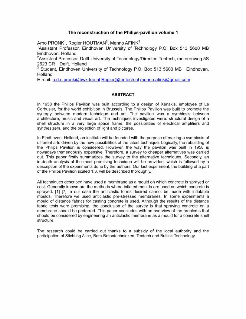
ABSTRACT In 1958 the Philips Pavilion was built according to a design of Xenakis, employee of Le Corbusier, for the world exhibition in Brussels. The Philips Pavilion was built to promote the synergy between modern technique and art. The pavilion was a symbiosis between architecture, music and visual art. The techniques investigated were: structural design of a shell structure in a very large space frame, the possibilities of electrical amplifiers and synthesizers, and the projection of light and pictures. In Eindhoven, Holland, an institute will be founded with the purpose of making a symbiosis of different arts driven by the new possibilities of the latest technique. Logically, the rebuilding of the Philips Pavilion is considered. However, the way the pavilion was built in 1958 is nowadays tremendously expensive. Therefore, a survey to cheaper alternatives was carried out. This paper firstly summarizes the survey to the alternative techniques. Secondly, an in-depth analysis of the most promising technique will be provided, which is followed by a description of the experiments done by the authors. Our last experiment, the building of a part of the Philips Pavilion scaled 1:3, will be described thoroughly.
All techniques described have used a membrane as a mould on which concrete is sprayed or cast. Generally known are the methods where inflated moulds are used on which concrete is sprayed. [1] [7] In our case the anticlastic forms desired cannot be made with inflatable moulds. Therefore we used anticlastic pre-stressed membranes. In some experiments a mould of distance fabrics for casting concrete is used. Although the results of the distance fabric tests were promising, the conclusion of the survey is that spraying concrete on a membrane should be preferred. This paper concludes with an overview of the problems that should be considered by engineering an anticlastic membrane as a mould for a concrete shell structure.
The research could be carried out thanks to a subsidy of the local authority and the participation of Stichting Alice, Bam-Betontechnieken, Tentech and Buitink Technology.
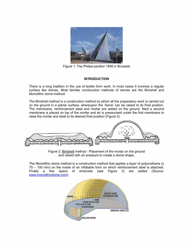
Figure 1: The Philips-pavilion 1958 in Brussels
INTRODUCTION There is a long tradition in the use of textile form work. In most cases it involves a regular surface like domes. Most familiar construction methods of domes are the Binishell and Monolithic dome method. The Binishell method is a construction method by which all the preparatory work is carried out on the ground in a planar surface, whereupon the ‘dome’ can be raised to its final position. The membrane, reinforcement steel and mortar are added on the ground. Next a second membrane is placed on top of the mortar and air is pressurised under the first membrane to raise the mortar and steel to its desired final position (Figure 2).
Figure 2: Binishell method - Placement of the mortar on the ground
and raised with air pressure to create a dome shape.
The Monolithic dome method is a construction method that applies a layer of polyurethane (± 70 – 100 mm) on the inside of an inflatable form on which reinforcement steel is attached. Finally a few layers of shotcrete (see Figure 3) are added (Source: www.monolithicdome.com).
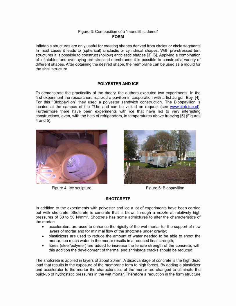
Figure 3: Composition of a “monolithic dome”
FORM Inflatable structures are only useful for creating shapes derived from circles or circle segments. In most cases it leads to (spherical) sinclastic or cylindrical shapes. With pre-stressed tent structures it is possible to construct (hollow) anticlastic shapes [3] [6]. Applying a combination of inflatables and overlaying pre-stressed membranes it is possible to construct a variety of different shapes. After obtaining the desired shape, the membrane can be used as a mould for the shell structure.
POLYESTER AND ICE
To demonstrate the practicality of the theory, the authors executed two experiments. In the first experiment the researchers realized a pavilion in cooperation with artist Jurgen Bey. [4]. For this “Blobpavilion” they used a polyester sandwich construction. The Blobpavilion is located at the campus of the TU/e and can be visited on request (see www.blob.tue.nl). Furthermore there have been experiments with ice that have led to very interesting constructions, even, with the help of refrigerators, in temperatures above freezing [5] (Figures 4 and 5).
Figure 4: Ice sculpture Figure 5: Blobpavilion
SHOTCRETE In addition to the experiments with polyester and ice a lot of experiments have been carried out with shotcrete. Shotcrete is concrete that is blown through a nozzle at relatively high pressures of 30 to 50 N/mm2. Shotcrete has some admixtures to alter the characteristics of the mortar:
• accelerators are used to enhance the rigidity of the wet mortar for the support of new layers of mortar and for minimal flow of the shotcrete under gravity;
• plasticizers are used to reduce the amount of water needed to be able to shoot the mortar; too much water in the mortar results in a reduced final strength;
• fibres (steel/polymer) are added to increase the tensile strength of the concrete; with this addition the development of thermal and shrinkage cracks should be reduced.
The shotcrete is applied in layers of about 20mm. A disadvantage of concrete is the high dead load that results in the exposure of the membrane form to high forces. By adding a plasticizer and accelerator to the mortar the characteristics of the mortar are changed to eliminate the build-up of hydrostatic pressures in the wet mortar. Therefore a reduction in the form structure
can be achieved compared to the liquid mortars.
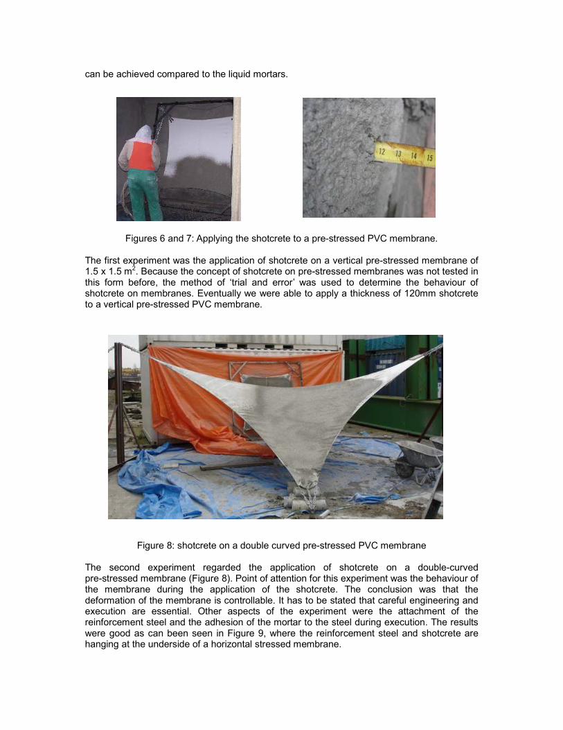
Figures 6 and 7: Applying the shotcrete to a pre-stressed PVC membrane.
The first experiment was the application of shotcrete on a vertical pre-stressed membrane of 1.5 x 1.5 m2. Because the concept of shotcrete on pre-stressed membranes was not tested in this form before, the method of ‘trial and error’ was used to determine the behaviour of shotcrete on membranes. Eventually we were able to apply a thickness of 120mm shotcrete to a vertical pre-stressed PVC membrane.
Figure 8: shotcrete on a double curved pre-stressed PVC membrane
The second experiment regarded the application of shotcrete on a double-curved pre-stressed membrane (Figure 8). Point of attention for this experiment was the behaviour of the membrane during the application of the shotcrete. The conclusion was that the deformation of the membrane is controllable. It has to be stated that careful engineering and execution are essential. Other aspects of the experiment were the attachment of the reinforcement steel and the adhesion of the mortar to the steel during execution. The results were good as can been seen in Figure 9, where the reinforcement steel and shotcrete are hanging at the underside of a horizontal stressed membrane.
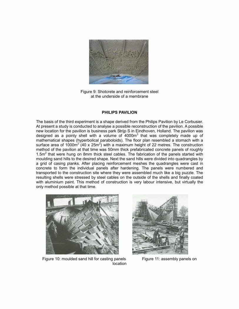
Figure 9: Shotcrete and reinforcement steel
at the underside of a membrane
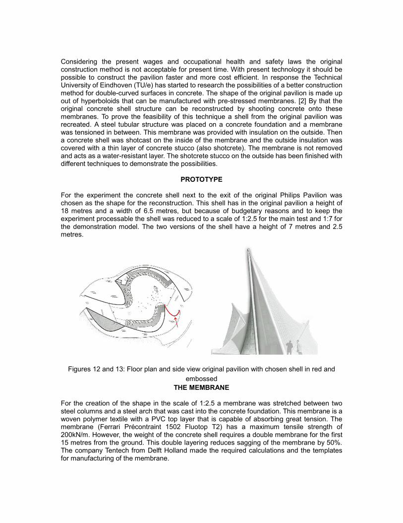
PHILIPS PAVILION The basis of the third experiment is a shape derived from the Philips Pavilion by Le Corbusier. At present a study is conducted to analyse a possible reconstruction of the pavilion. A possible new location for the pavilion is business park Strijp S in Eindhoven, Holland. The pavilion was designed as a pointy shell with a volume of 4000m3 that was completely made up of mathematical shapes (hyperbolical paraboloids). The floor plan resembled a stomach with a surface area of 1000m2 (40 x 25m2) with a maximum height of 22 metres. The construction method of the pavilion at that time was 50mm thick prefabricated concrete panels of roughly 1.5m2 that were hung on 8mm thick steel cables. The fabrication of the panels started with moulding sand hills to the desired shape. Next the sand hills were divided into quadrangles by a grid of casing planks. After placing reinforcement meshes the quadrangles were cast in concrete to form the individual panels after hardening. The panels were numbered and transported to the construction site where they were assembled much like a big puzzle. The resulting shells were stressed by steel cables on the outside of the shells and finally coated with aluminium paint. This method of construction is very labour intensive, but virtually the only method possible at that time.
Figure 10: moulded sand hill for casting panels Figure 11: assembly panels on location
Considering the present wages and occupational health and safety laws the original construction method is not acceptable for present time. With present technology it should be possible to construct the pavilion faster and more cost efficient. In response the Technical University of Eindhoven (TU/e) has started to research the possibilities of a better construction method for double-curved surfaces in concrete. The shape of the original pavilion is made up out of hyperboloids that can be manufactured with pre-stressed membranes. [2] By that the original concrete shell structure can be reconstructed by shooting concrete onto these membranes. To prove the feasibility of this technique a shell from the original pavilion was recreated. A steel tubular structure was placed on a concrete foundation and a membrane was tensioned in between. This membrane was provided with insulation on the outside. Then a concrete shell was shotcast on the inside of the membrane and the outside insulation was covered with a thin layer of concrete stucco (also shotcrete). The membrane is not removed and acts as a water-resistant layer. The shotcrete stucco on the outside has been finished with different techniques to demonstrate the possibilities.
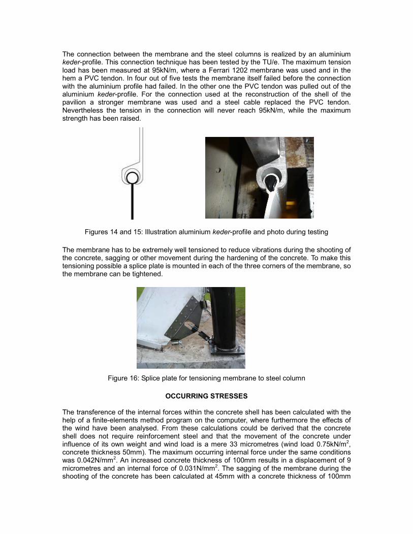
PROTOTYPE For the experiment the concrete shell next to the exit of the original Philips Pavilion was chosen as the shape for the reconstruction. This shell has in the original pavilion a height of 18 metres and a width of 6.5 metres, but because of budgetary reasons and to keep the experiment processable the shell was reduced to a scale of 1:2.5 for the main test and 1:7 for the demonstration model. The two versions of the shell have a height of 7 metres and 2.5 metres.
Figures 12 and 13: Floor plan and side view original pavilion with chosen shell in red and
embossed
THE MEMBRANE For the creation of the shape in the scale of 1:2.5 a membrane was stretched between two steel columns and a steel arch that was cast into the concrete foundation. This membrane is a woven polymer textile with a PVC top layer that is capable of absorbing great tension. The membrane (Ferrari Précontraint 1502 Fluotop T2) has a maximum tensile strength of 200kN/m. However, the weight of the concrete shell requires a double membrane for the first 15 metres from the ground. This double layering reduces sagging of the membrane by 50%. The company Tentech from Delft Holland made the required calculations and the templates for manufacturing of the membrane.
The connection between the membrane and the steel columns is realized by an aluminium keder-profile. This connection technique has been tested by the TU/e. The maximum tension load has been measured at 95kN/m, where a Ferrari 1202 membrane was used and in the hem a PVC tendon. In four out of five tests the membrane itself failed before the connection with the aluminium profile had failed. In the other one the PVC tendon was pulled out of the aluminium keder-profile. For the connection used at the reconstruction of the shell of the pavilion a stronger membrane was used and a steel cable replaced the PVC tendon. Nevertheless the tension in the connection will never reach 95kN/m, while the maximum strength has been raised.
Figures 14 and 15: Illustration aluminium keder-profile and photo during testing
The membrane has to be extremely well tensioned to reduce vibrations during the shooting of the concrete, sagging or other movement during the hardening of the concrete. To make this tensioning possible a splice plate is mounted in each of the three corners of the membrane, so the membrane can be tightened.
Figure 16: Splice plate for tensioning membrane to steel column
OCCURRING STRESSES The transference of the internal forces within the concrete shell has been calculated with the help of a finite-elements method program on the computer, where furthermore the effects of the wind have been analysed. From these calculations could be derived that the concrete shell does not require reinforcement steel and that the movement of the concrete under influence of its own weight and wind load is a mere 33 micrometres (wind load 0.75kN/m2, concrete thickness 50mm). The maximum occurring internal force under the same conditions was 0.042N/mm2. An increased concrete thickness of 100mm results in a displacement of 9 micrometres and an internal force of 0.031N/mm2. The sagging of the membrane during the shooting of the concrete has been calculated at 45mm with a concrete thickness of 100mm
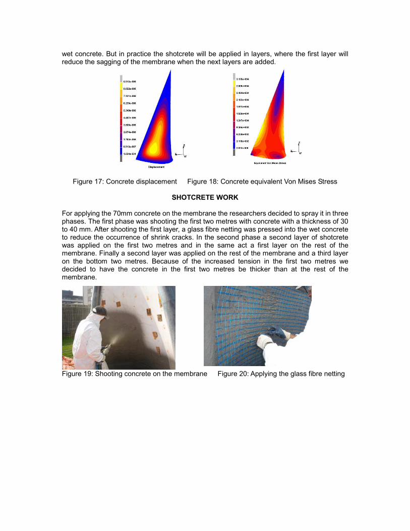
wet concrete. But in practice the shotcrete will be applied in layers, where the first layer will reduce the sagging of the membrane when the next layers are added.
Figure 17: Concrete displacement Figure 18: Concrete equivalent Von Mises Stress
SHOTCRETE WORK
For applying the 70mm concrete on the membrane the researchers decided to spray it in three phases. The first phase was shooting the first two metres with concrete with a thickness of 30 to 40 mm. After shooting the first layer, a glass fibre netting was pressed into the wet concrete to reduce the occurrence of shrink cracks. In the second phase a second layer of shotcrete was applied on the first two metres and in the same act a first layer on the rest of the membrane. Finally a second layer was applied on the rest of the membrane and a third layer on the bottom two metres. Because of the increased tension in the first two metres we decided to have the concrete in the first two metres be thicker than at the rest of the membrane.
Figure 19: Shooting concrete on the membrane Figure 20: Applying the glass fibre netting
The concrete was shot with the wet method. This means that the mortar is mixed with water and pushed through a hose by a worm screw. In the nozzle air is added to the concrete under high pressure in order to shoot the concrete out of the nozzle. With the dry method the mortar is blown through the hose by compressed air and the water is added in the nozzle. The advantage of the wet method is that the force of the shot is less than the dry method. Therefore a smaller percentage of gravel is being rebounded by the membrane and the creation of dust is reduced. The disadvantage of the wet method is that every interruption in the work means that the hose has to be emptied and cleaned. Because of the minimal surface area that had to be shot with concrete every phase a lot of concrete was wasted with cleaning the hose. This loss in relation to the area that is worked on is reduced with the increase of the area.
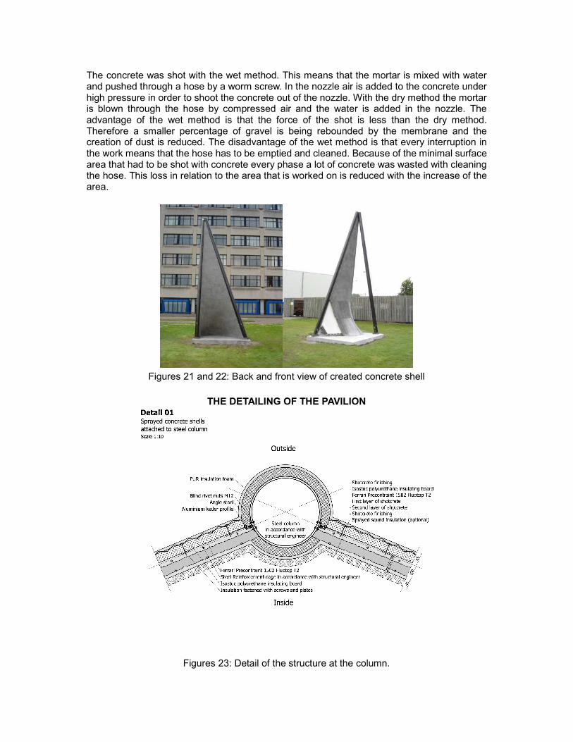
Figures 21 and 22: Back and front view of created concrete shell
THE DETAILING OF THE PAVILION
Figures 23: Detail of the structure at the column.
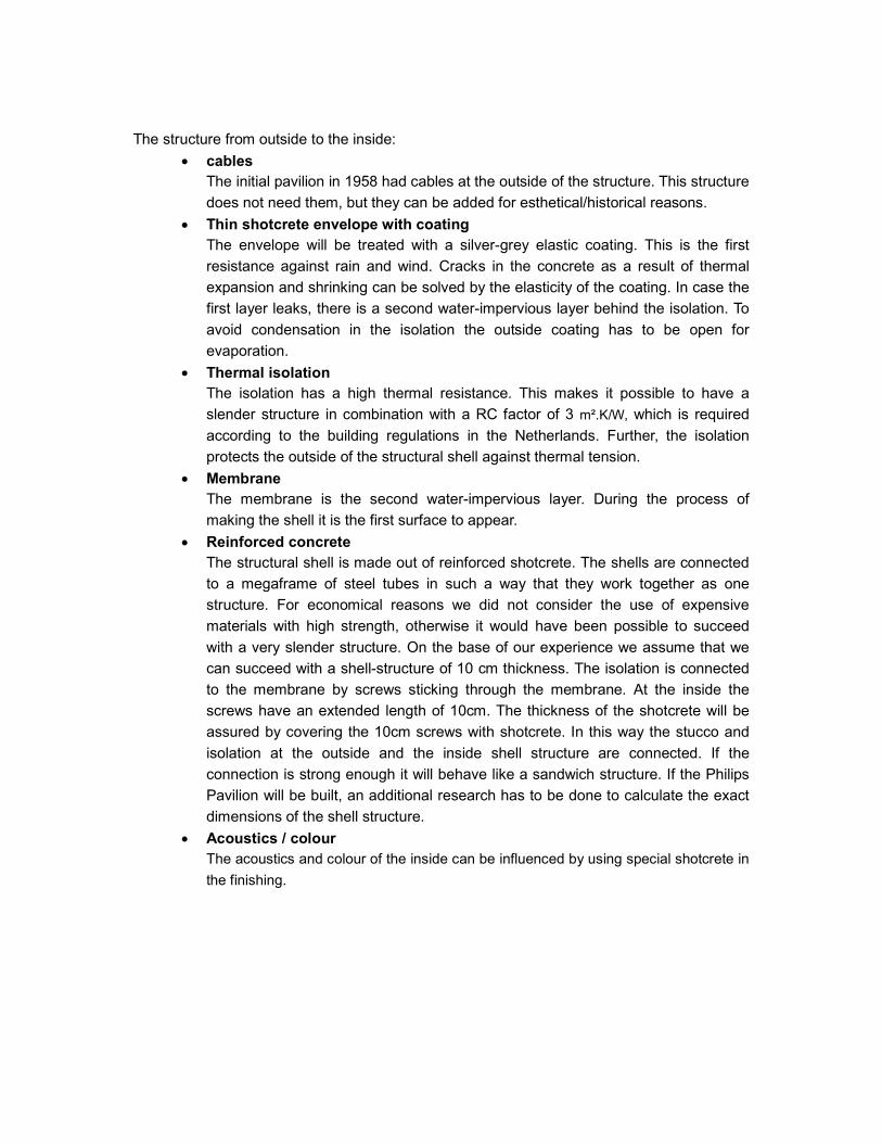
The structure from outside to the inside:
• cables
The initial pavilion in 1958 had cables at the outside of the structure. This structure
does not need them, but they can be added for esthetical/historical reasons.
• Thin shotcrete envelope with coating
The envelope will be treated with a silver-grey elastic coating. This is the first
resistance against rain and wind. Cracks in the concrete as a result of thermal
expansion and shrinking can be solved by the elasticity of the coating. In case the
first layer leaks, there is a second water-impervious layer behind the isolation. To
avoid condensation in the isolation the outside coating has to be open for
evaporation.
• Thermal isolation
The isolation has a high thermal resistance. This makes it possible to have a
slender structure in combination with a RC factor of 3 m².K/W, which is required
according to the building regulations in the Netherlands. Further, the isolation
protects the outside of the structural shell against thermal tension.
• Membrane
The membrane is the second water-impervious layer. During the process of
making the shell it is the first surface to appear.
• Reinforced concrete
The structural shell is made out of reinforced shotcrete. The shells are connected
to a megaframe of steel tubes in such a way that they work together as one
structure. For economical reasons we did not consider the use of expensive
materials with high strength, otherwise it would have been possible to succeed
with a very slender structure. On the base of our experience we assume that we
can succeed with a shell-structure of 10 cm thickness. The isolation is connected
to the membrane by screws sticking through the membrane. At the inside the
screws have an extended length of 10cm. The thickness of the shotcrete will be
assured by covering the 10cm screws with shotcrete. In this way the stucco and
isolation at the outside and the inside shell structure are connected. If the
connection is strong enough it will behave like a sandwich structure. If the Philips
Pavilion will be built, an additional research has to be done to calculate the exact
dimensions of the shell structure.
• Acoustics / colour
The acoustics and colour of the inside can be influenced by using special shotcrete in
the finishing.
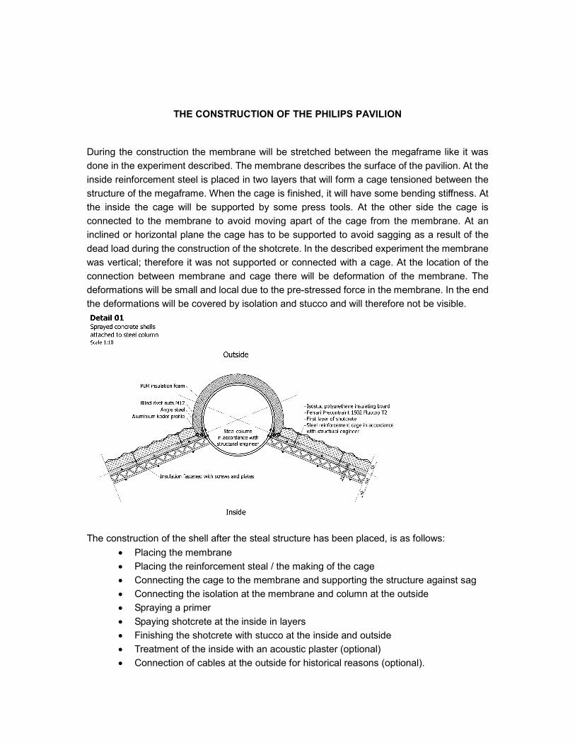
THE CONSTRUCTION OF THE PHILIPS PAVILION
During the construction the membrane will be stretched between the megaframe like it was
done in the experiment described. The membrane describes the surface of the pavilion. At the
inside reinforcement steel is placed in two layers that will form a cage tensioned between the
structure of the megaframe. When the cage is finished, it will have some bending stiffness. At
the inside the cage will be supported by some press tools. At the other side the cage is
connected to the membrane to avoid moving apart of the cage from the membrane. At an
inclined or horizontal plane the cage has to be supported to avoid sagging as a result of the
dead load during the construction of the shotcrete. In the described experiment the membrane
was vertical; therefore it was not supported or connected with a cage. At the location of the
connection between membrane and cage there will be deformation of the membrane. The
deformations will be small and local due to the pre-stressed force in the membrane. In the end
the deformations will be covered by isolation and stucco and will therefore not be visible.
The construction of the shell after the steal structure has been placed, is as follows:
• Placing the membrane
• Placing the reinforcement steal / the making of the cage
• Connecting the cage to the membrane and supporting the structure against sag
• Connecting the isolation at the membrane and column at the outside
• Spraying a primer
• Spaying shotcrete at the inside in layers
• Finishing the shotcrete with stucco at the inside and outside
• Treatment of the inside with an acoustic plaster (optional)
• Connection of cables at the outside for historical reasons (optional).
THE CONTROL OF THE FORM
The membrane will deform as a result of the dead load. As long as the shotcrete is wet, it is
the main cause of the sagging of the structure. The sag of the membrane can be
compensated by an initial “negative sag”. The connection of the bending-stiff cage with the
membrane will have a positive effect on the sag. If necessary the cage can be supported. The
described structure has to be calculated as a form-active structure (the membrane) in
combination with a vector-active structure (the cage). With computer programs such as Easy
it is possible to calculate the sag of the membrane in combination with bending-stiff elements.
The primer contributes to an excellent connection between membrane and concrete during
the construction and afterwards. After the first layer of shotcrete has rigidized it will support the
structure and will be able to bear the dead load of the next layer of shotcrete. Due to all the
measurements described, the deformation of the structure will be a few centimetres. The
tolerances in the surface of the shell are much more as we are used to. If a connection with
another building element has to be made, it is recommended to make the connection at the
edge of the shell because there the tolerances will be smaller. In other cases special
measurements have to be made for these connections.
THE REINFORCEMENT STEAL
The reinforcement steal has to be bended in the right form. The authors expect this to be a
minor problem because of the large curvature. The Philips Pavilion is made out of hyperbolic
shells which is a regularly deformed surface. If it is possible to follow the regularity of the shell
with steal bars, bending can even be avoided. An other way to avoid the problem of bending
reinforcement steal is the use of fibers that can be sprayed within the shotcrete. More
research needs to be done to use fibers in curved building structures.
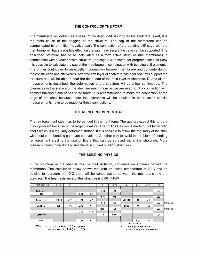
THE BUILDING PHYSICS
If the structure of the shell is built without isolation, condensation appears behind the
membrane. The calculation below shows that with an inside temperature of 20˚C and an
outside temperature of -10˚C there will be condensation between the membrane and the
concrete. The heat resistance of this structure is 0.06 m².K/W.
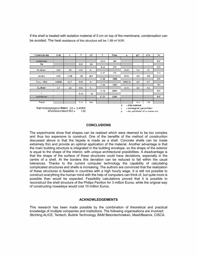
If the shell is treated with isolation material of 5 cm on top of the membrane, condensation can
be avoided. The heat resistance of this structure will be 1.99 m².K/W.
CONCLUSIONS The experiments show that shapes can be realized which were deemed to be too complex and thus too expensive to construct. One of the benefits of the method of construction discussed above is that the façade is made as a shell. Concrete shells can be made extremely thin and provide an optimal application of the material. Another advantage is that the main building structure is integrated in the building envelope, so the shape of the exterior is equal to the shape of the interior, with unique architectural possibilities. A disadvantage is that the shape of the surface of these structures could have deviations, especially in the centre of a shell. At the borders this deviation can be reduced to fall within the usual tolerances. Thanks to the current computer technology the capability of calculating complicated structures and shells is increasing. The authors are convinced that the realization of these structures is feasible in countries with a high hourly wage. It is still not possible to construct everything the human mind with the help of computers can think of, but quite more is possible than would be expected. Feasibility calculations proved that it is possible to reconstruct the shell structure of the Philips Pavilion for 3 million Euros, while the original way of constructing nowadays would cost 10 million Euros.
ACKNOWLEDGEMENTS This research has been made possible by the combination of theoretical and practical knowledge of multiple companies and institutions. The following organisations are involved: Stichting ALICE, Tentech, Buitink Technology, BAM Betontechnieken, Maxit/Beamix, CISCA.
REFERENCES [1] Chilton, J.; “Heinz Isler, The enigineer's contribution to contemporary Architecture” august 2000 ISBN 0 72772878 4. [2] Herzog T. Pneumatische Constructionen, Bauten aus Membranen und Luft 1976 ISBN 3 7757 0083 8 BK U II 243 [3] Houtman, R., Pronk, A.D.C.,”Blob Arcitecture or Structural Fabric”, proceedings of the International Workshop on Textile Architecture, Berlin 2002 [4] Onate E. and Kroplin B. “Textile Composites and Inflatable Structures” (2005) Pronk A.D.C. Houtman R. “Making Blobs with a textile Mould” (page 305) ISBN 13 978-14020-3317-9 [5] Pronk A.D.C., Osinga D.R.’’Making igloos in the summer’’, proceedings of the International Conference on Textile Composites and Inflatable Structures 2 Stuttgart (2005) (page 218) [6] Ruhle H. Raumliche Drachtragwerke, Konstruktion und Ausfuhrung Band 1 p. 158 p. 244 [7] Sobek W. Auf pneumatische gestutzten Schalungen herstelte Betonschalen (1987) Stuttgart p.1 t/m p.34 Isbn 3-9801085-1-1