
THE R 0 CONSTRUCTOR
68
THE R ADI 0 CONSTRUCTOR Vol. 24 Na. 8 MARCH 1971 %%/////%/////í///%/I/i////ltlllE'"IEIIIa\\\\\,\\`\ G ;. ° : __ MODIFYING THE 'TRIO' 9R -59DE Rx (PART ONELA DIRECT CONVERSION RECEIVERS TIMER WITHOUT ELECTROLYTICS Eight Constructional Projects Alan, other features 1 www.americanradiohistory.com
Transcript of THE R 0 CONSTRUCTOR
THE
R ADI 0 CONSTRUCTOR Vol. 24 Na. 8 MARCH 1971
%%/////%/////í///%/I/i////ltlllE'"IEIIIa\\\\\,\\`\
G ;. ° :
__
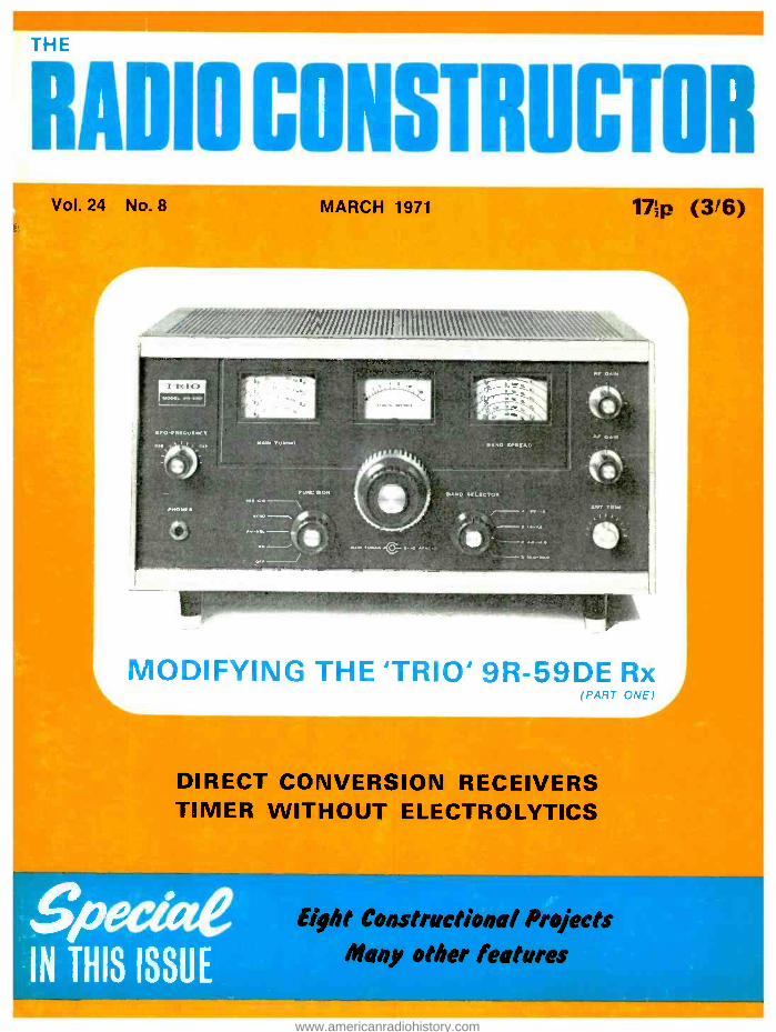
MODIFYING THE 'TRIO' 9R -59DE Rx (PART ONELA
DIRECT CONVERSION RECEIVERS TIMER WITHOUT ELECTROLYTICS
Eight Constructional Projects Alan, other features 1
www.americanradiohistory.com

ACI07 ACI26 ACI27 AC I28 AC I76 ACI87 ACI88 ACY I7 ACYI8 ACYI9 ACY20 ACY21 ACY22 ACY40 ACY4I ADI40 ADI49 AD161 AD162 AFI14 AF115 AFI16 AF117 AF118 AF124 AF126 AF139
AF186 AF239 A5Y26 ASY27 ASY28 ASY29 ASZ21 AUYIO BA115 BC 107 BC 108 BC109 BC M7 BC148 BCM9 BCI58 BCI69C BC 182 BC182L BC 183 BC183L BC184 BC184L BC186 BC212 BC212L BCY 30 BCY31 BCY32 BCY33 BCY34 BCY38 BCY70 BCY7I BCY72 BDI21 BDI23 BD124 BDY20 BEI IS 13E163
BF167 BF173 BF178 BF180 8E181 BF184 8E185 BF194 BF195 0E196 BF200 BFXI3 BFX29
BFX84 BFX85 BFX86 BFX87 BFX88 BFY50 BFXSI BFY52 BFY53 BFY90 BSXI9 BSX20 BSX21 BSY27
L/Np L/Np
37 BSY29 . . 25 25 00795A . 15
25 BY100 . . 30 20 130X10. . 15 25 BYZIO. . 40 30 BYZI2. . 30 30 8YZ13. . 20 29 BZY88 Series 20 3.3Vto30V 1S
20 19 DISTI . 45 19 MJE520 75 19 1.11480 . 97 1S MJ481 . 1.25 15 04}190 . 100 S5 MJ491 . 1.35 57 MPFI02 43 37 MPF103 37 37 MPF104 37 25 MPF105 40 25 25 NKT124 30 25 NKTI25 40 44 NKT126 37 25 NKT128 17 NKT135 37 NKT137 32
NKT210 25 40 NKT211 25 37 NKT2I2 20 25 NKT2I3 25 30 NKT214 23 22 NKT2I5 21
30 NKT216 46 37 NKT217 50
1.50 NKT218 25 8 NKT219 25
12 NKT223 27 12 NKT224 25
12 NKT225 21
15 NKT229 29 1S NKT237 31
15 NKT238 19 17 NKT239 23 19 NKT240 20 12 NKT241 21
10 NKT242 1S
9 NKT243 56 - 9
15 NKT244 17 15 NKT245 17
90 NKT26I 21
17 NKT262 19 12 NKT264 21 25 NKT27I 18 48 NKT272 17 SO NKT274 18 20 NKT275 23 25 NKT279A 12 30 NKT281 29 19 NKT302 87 37 NKT304 79 16 NKT351 75
1.10 NKT401 71 1.10 NKT402 77 103 NKT403 65 105 NKT404
25 NKT405 40 NKT406 62 25 NKT420 1.83 30 NKT45I 58 52 NKT452 54 37 N1(0453 50 37 NKT603F 30 25 NKT613F 30 25 NKT674F 30 17 NKT676F 30 15 15 NKT677F 28 35 NKT7I3 29 2S NKT717 44 31 NKT734 26
NKT736 32 26 NKT773 25 34 NRT781 29 25 NKT10339 25 30 NKT10419 19 25 NKT10439 27 23 NKTI0519 22 19 NKT20329/ 20 0013 31
16 N1(180111 67 67 NKT80112 83 16 NKT80113100 16 NKT80211 75 37 NKT80212 75 20 NKT80213 75
2s 26
60 79
L/Np L/Np
NKT80214 NKT80215 NKT80216
OAS OA10 0A47 0A70 0A73 OA79 OA81 OA85 0A90 DA91 0A95 0A200 OA202 OC19 OC20 0C22 OC23 OC24 0C25 OC26 OC28 0C29 0C35 OC36 0C41 OC42
0C44 0C45 007 0072 OC75 OC76 0077 OC81 OCBID OCeIZ 0082 .
OC82D OC83 .
OC84 .
0C139 .
0C140 .
OCI70. 0C171 .
0C200 .
0C201 .
OC202 .
0C203 .
0C204 .
OC205 .
0C206 .
0C207 .
OCP71 /M
ORPI2 ORP60 ORP61 P346A 5T140 ST141 TD716 TIP3IA TIP32A V405A
ZTX108 ZTX300 ZTX302 ZTX303 ZTX304 ZTX314 ZTX320 ZTX3l0 ZTX500 ZTX501 Z TX 502 ZTX503 ZTX504
1N34A IN60 1N64 I N82A IN87A 1N914 I N4001 1N4002 1N4003 I N4004 I N4005 1N4006 1N4007 1N4148
75 75 75
20 25
20302 .
20371 .
20374 .
2NI74 .
2N385A/ 2N388A 2N404 .
25696 .
244697 244698 25706 .
2N706A 25708 .
2N711 .
1 2N711A 1 2N911 .
37 2N914 .
97 2N918 .
47 2NI090 60 2N1091 60 2N1131 37 2N1132 33 2N1302 60 2N1303 75 2N1304 SO 2N1305 63 2N 1306 25 2N 1307
30 2N1308 2N1309
1S 2N1507 15 2N1613 15 2N1711 23 2N2147 23 2N2148 25 2N2160 40 2N2368 23 2N2369 20 5S 2N2369A 25 2N2646 15 2N2904 23 2N2904A 25 2N2905 25 2N2905A 35 2N2906 25 2N2906A 30 2N2926. al
37 colours 47 2N3053 63 2N3054 37 2N3055 40 2N3702 65 2N3703 75 2N3704 75 2N3705 47 2N3706
2N3707 SO 2N3708 60 2N3709 40 2N3710 19 2N3711 15 2N3819 20 2N3820 60 2N3826 62 74
46
11
13 18 18 27 11
30 18 16 16
20 17 40
20 20 20 47 23
254058 2444060 254061 254062 254284 254287 254289 2444871 34484 3N128 344140 3NI41 3N152 40250 40309 40310 40312 40320 40360 40361 40362
7 40406 7 40407 7 40408
10 40409 10 40468A 12 40600 15 40601 20 40602 7 40603
19 IS 25 80
75 23 15 17 30 10 12 16
37 37 SO
20 42 30 33 30 30 20 20 25 25 30 30 34 31 23 22 25 82 63 62 17 17
10
ss 63 75 11
10 11
10
11
7 9 9 9
35 60 30
17 20 20 20 15 15 15 40
1"30 69 76 73 86 55 33 45 48 36 43 48 58 56 39 51 54 35 58 SS
40 K
TERMS: Cash with order please. Postage & packing - 10Np Inland, 25Np Europe, 60Np elsewhere. All goods guaranteed. ALL ORDERS DESPATCHED WITHIN ONE WORKING DAY OF RECEIPT. 1971 Retail Catalogue now available: 5Np stamp for postage appreciated.
LSTCOMPONENITS LTD MAIL ORDER DEPT. (RC)
7 COPTFOLD ROAD
BRENTWOOD. ESSEX
VSlors welcome al our new retail shop - same address
Components RESISTORS Carbon Film j 6 i Watt 5'j,.
2 Np each Packs of 10 (of one value /wattage)
IS Np per pack.
PRESETS P.C. Type 03 Watt
Standard size 7 Np Sub -miniature 5 Np
(Available vertical or horizontal mounting Usual values 100 ohms to 5 Meg.
POTENTIOMETERS Log or Lin Less switch - 17 Np Log or Lin DP switch - 27 Np Log or Lin Stereo L/S - SO Np Values: 5k. 10k. 25k, 50k. ICOk, 250k, 500k, I Meg. 2 Meg.
CAPACITORS Mullard Miniature Electrolytic
Mfd. Volt.Wkg. - C426 Series 2.5 16 8Np 10 16 6Np 20 16 6Np 40 16 6Np 80 16 6Np 1.6 25 8Np 6.4 25 6Np 12.5 25 6Np 25 25 6Np 50 25 6Np 80 25 6Np
1 40 8Np 4 40 6Np 8 40 6Np
16 40 6Np 32 40 6Np 50 40 6Np
Mullard Metallised Polyester 250v Mfd. Mfd, .01 3Np 12 SNp .015 3Np 33 7Np .022 3 Np 47 8 Np .033 3Np .68 11 Np .547 4Np 1.0 14 Np 068 4Np I5 20Np i 4Np 2.2 24 Np .15 5Np
Mullard Electrolytic - C437 Series
MI d. ValsWkg. 250 16 9Np 400 16 12 Np 640 16 15 Np 1000 16 18 Np IW 25 9Np 250 25 12 Np 400 25 15 Np 640 25 18 Np 100 40 9Np 160 40 12Np 250 40 15 Np 400 10 18 Np
Mullard Sub -Miniature Ceramic Plate - C333 Series 63 volt working. Range 1.8pí to
Pacvks ofs6a(any values) values)
- 30 Np
NEW ! SN74N SERIES TTL LOGIC
NOW FRON LS.T. - FULL. SPECIFICATION TEXAS INDUSTRIAL
INTEGRATED CIRCUITS AT ECONOMY PRICES
SN7403N SN7401N 5N740[N SN740IN SN7404N SN7413N SN741sN SN7422N SN74lON SN7443N 5574415 SN74S3N
SN7453N 5N7463N
SN7473N SN7472N SN7473N SN747IN SN7473N SN7475N SN74B3N SN7493N SN749?N SN7493N SN7411N
I-49 50-99 100+
Quad 2 -input NAND gate Quad 2-input NAND gate open collector 1, 32 27 21
Quad 2 -input NOR gate
Quad 2 -input NOR gate open collector 35 30 25
Hex Inverter Triple 3 -input NAND gate Schmidt Trigger 45 40 35
Dual 4 -input NAND pate 8 -input NAND gate 32 27 12
Dual 4 -input NAND Buffer BCD to decimal decoder TTL output N.12 LIDO 83
Expandable Dual 2 -wide 2 -input AND -OR -INVERT gate 32 27 12
Expandable 4 -wide 3 -input AND -OR- INVERT gate Dual 4 -input expander
32 27 21
J-K Flip -flop 45 40 35 j-K Muter -Slave Flip -lop I
Dual I -K Master -Slave Flip-flop I
SO 4S 41 Dual D type Edge -Triggered Flip -flop I
Quadruple Bistabls Latch 65 60 SS
Dual ) -K Master -Slave Flip -flop with Preset 6 Clear S5 SO 47
Four -bit Binary Full.Adder 0.30 11.10 61.10
Decade Counter Divide -by -12 Counter tourbit Binary Counter BCD to decimal Decoder /Driver L1Á5 6120 11.15 (Replaces the obsolete SN7441 AN )
MIX PRICES: Devices may be mixed to qualify for quantity price Larger quantities - prices on sepli455i011
L1.12 LI 00 87
LINEAR AND DIGITAL I /C4
CA3804 LI.6U CA3005 L1.20 CA3011 75 CA1013 LIAS CA3O14 [1.25 CA3018 85 CA3020 L1.30 CA3028A 75 CA3015 L1.25 CA3043 L1.40 CA3044 41.20 CA3046 75 CA3047 41.40 CA3048 a.05 CA3049 LI.N CA3052 LI.65
BARGAIN OP-AMPS I I
LM709C - 617Np (DIL high got op-amp) LM741CN 95Np (equiv. SN71741P)
PC1006/I Multimeter Sensi-
.rKtï ckc°
áese.ii accessories n.55
FAIRCHILD
I -II 12 -24 25 + 0.900 40Np 35Np 31 Np vL914 40Np 35 Np 32Np ,L923 53 Np SO Np 47 Np
Devices may be mixed to qualify for quantity price.
G.E. (USA)
PASSO Pre -amp PA214 I Watt Amp PA237 2 Watt Amp PA246 S Watt Arte PA424 Zero Volt Switch
MISCELLANEOUS
TH9013P Toshiba 20 Wan Hybrid IC Amp ICI0 Sinclair -
SL40SA Plessey New Design - - -
MULLARD
TAA363 Linear Arne TAA293 General Purpose Amp TAA3I0 Record /Playback Amp TAA320 MOS LF Amp TAD100 IC Receiver TADI10 AM /FM Receiver
[1.10 L1.00 L167 [263 L165
H.47 13.75 [2.12
75 Ne L1.N [150
65 Np £1.97 11.97
NEONS Miniature neon bulbs: 0.6mA 65vac 90vdc. Pack of 5 for 30 Np Panel neon indicators, mains volt- age. Red lenses - round, square or arrow- shaped faces Each 20 Np
VEROOOARD 2.5" z I7 z .15" 57 Np 2.5" x 5" x .15" 23 Np 2.r x 3.75" x .15" 19 Np 3.75" x 17" x .15" 79 Np 3.75' x 5" x .15" 30 Np 3.75" x 3.75" x .15" 22 Np 23' x 5" x .I" 25 Np 25" x 3.75" x .I" 23 Np
e pfiacse : pctte rs f 50-for
38 Np Np
Bargain Pack, 36 square inches of various sixes. .15" 8J/or .1" SONp
HEATSINKS TO -5 (Clip-on) pack of 4 for 1S Np FINNED type for 2 o TO -3 ready drilled at 43 Np FINNED type undrilled for plastic power at 34 Np
BOOKS G.E. Transistor Manual L1Á7 R.CA. Transistor Manual L1Á0 Designers Guide to British Tran- sistors (data book) L1.25 R.C.A. Hobby Circuits Manual L1Á0 110 Semiconductor Projects
(Manton) L1.25 Zener Diode Handbook 84 Np Photocell & Solarcell
Handbook $4 Np Thyristor (S.C.R.) Handbook L100
ULTRASONIC TRANSDUCERS
Operate at 40kc /s. Can be used for remote control systems without sables or electronic links. ye 1404 transducers can smit and receive.
FREE: With each pair our complete transmitter and receiver circuit. PRICE £5.90 Pair
(sold only in pairs)
IOR DDI 19
DOOO DD175 OD176 DDI77 013180 00184 00190 EP50A
SIM 54M B2M
B1M CSI20
Heat sink compound - Silicone grease - - - Bargain pack of five I Watt Zener diodes - -
4 pieces 100 PRV Rectifiers 500mA - - 2 pieces 200 PRY Rectifiers SOOmA - 2 pieces 400 PRY Rectifiers 500mA - Bargain Transistor pack 2 AF + RF - - - Assortment of RI. audio 6 power transistor solar cell 6 diode Pack of 4 assorted solar cells - - - - Solar motor (operates front 54M) - - - Silicen Solar cell IO -16mA - Silicon Solar cell 25-400A Low cost Selenium solar cell
Selenium cell in protective case
Cadmium Sulphide photoconductive all -
Only part of the International Rectifier "Diamond Lite range are listed.
Send for free omogue or ask your 1 «041 component atocknt.
aNp 97 Np SpNp 30Np SO Np 57 Np 1167
50 Np L1.97
95 Np 1167
63 Np 75 Np 9E Np
TRIACS
2N5756 40486 40410 40412 40512
40176 SC146B SC146o ST2
2.5A (RMS) 400 PIV TO -5 Mod. - - 6 Amp (ß04S1 400 PIV TO -5 Mod. - - 6 Amp (ENS) 400 PIV TO-66 - - - - 6 Amp (RMS Q 75' Amb.) 400 Ply" - - 2.2 Amp (RMS (ry 25° Amb.) 400 PIV' -
- 'These types have integral triggering ISA (RMS) 400 PIV TO-66 - - 10 Amp 200 PIV Plastic Flu -pack - - 10 Amp 400 PIV Plastic flat -pack - - Bi- lateral avalanche trigger diode - - -
95 Np .1.0 LI61 LISP 11.45
0.70 015 L1.76
47 Np
ZENON DIODES
400rtW 10% GLASS CASE TEXAS Mfr.
152036 3.6 volt 152039 3.9 volt 152043 volt 152047 4.7 volt 152056 56 volt 112062 61 volt 152066 68,011 152075 7.5 volt Prices: 1 -24 ISNp 25.99
52002 81 volt 52100 10 volt 52110 11 volt 52120 12 volt 52140 16 volt 52180 II volt 52270 27 volt 52300 30 vok INp 100 + 9Np
TNYRIETORS
CRI /051C I Amp 50 PIV 7O -5 40Np CRI /401C I Amp 400 PIV TO -5 50 Np 253525 5 Amp 400 PIV TO-66 0.09 40739 10 Arne 400 Ply Stud Mtg. £1.45
ENCAPSULATED {RIDGES
Type No. Current Rw, Volts WOOS I Amp 50 5111Np
WN 1 Amp 600 6501p
www.americanradiohistory.com
Heath (Gloucester) Ltd. are manufacturers of Britain's most popular elec- tronic kits. Heathkit models are the beginner's as well as the experienced kit builder's first choice. Everything you need right down to the last nut and bolt is included in every kit. The Heathkit unique one -step -at -a -time con- struction manual is your guarantee to first -time success. Whatever your requirements, be it Hi -Fi, Radio, R/C models, we aim to please. Hundreds of models to choose from . . . your first step is to send for the Free Heath - kit catalogue and discover the unique satisfaction you get from building the oest.
HEATH (Gloucester) LTD. GLOUCESTER GL2 SEE'
Please send me a FREE Heathkit Catalogue A Schlumberger Company
(BLOCK CAPITALS PLEASE)
NAME
ADDRESS
POST CODE
53/3/71
f. f \12(1-1 1971 453
www.americanradiohistory.com

REVERBERATION UNIT KIT A new, all silicon version of our self- contained, 6 transistor, reverberation chamber to which microphones, instruments, tuners or tape recorders may be connected for added dimen- sional effect. The output is suitable for most amplifiers and the unit is especially suitable for use with electronic organs. A ready -built spring and transducer assembly is used (C2.95 (59/ -) if bought separately).
Complete easy -to -build kit, with constructional notes and circuits L7.50 (L7.10.0) Pre -drilled and printed case E1.70 (34/ -) All parts available separately. Send 5p (1 / -) for circuit and construction details.
WAH -WAH PEDAL KIT SELECTIVE AMPLIFIER MODULE. The basis of the Wah -Wah pedal. Kit contains all the components to build a 2- transistor circuit module, also the sockets, control, etc., required for the constructor to assemble his own design. L1.75 (35/ -). Assembled and tested module L2.12 (42/5).
FOOT VOLUME CONTROL PEDAL. Foot pedal unit in very strong fawn plastic. Fitted with output lead and plug for con- nection to guitar amplifier. May be used for volume control or converted to Wah -Wah by adding the module. Pedal unit now only L5.12 (£5.2.5). Complete kit for Wah -Wah pedal now only L6.50 (C6.10.0).
I.C. STEREO AMPLIFIER KIT A new kit from Wilsic to build a hi -fi integrated circuit stereo amplifier 3 watts per channel with full tone controls and attractive veneered cabinet, or may be built into plinth unit. Complete amp kit with stabilised power pack L21.45 (L21.9.0) with economy power pack £18.50 (C18.10.0). Cabinet kit: teak 731p (14/8) mahogany 66p (13/2). Full plans and detailed prices 10p (2/ -). New catalogue 1Sp (3/ -) with special discount order form.
WILSIC ELECTRONICS LIMITED 6 COPLEY ROAD, DONCASTER, YORKSHIRE
LASKYS EXCLUSIVE DIGITAL ' CLOCK
12 hour alarm Mains operation
Auto sleep switch Built -in alarm buzzer
Shock and vibration proof Hours, mins. and secs. read -off
Silent operation synchronous motor Forward and backward time adjustment
Made especially for Laskys by famous maker
HUNDREDS OF APPLICATIONS This unique DIGITAL CLOCK is now available EXCLU- SIVELY FROM LASKY'S in chassis form for you to mount in any housing that you choose. All settings are achieved by two dual concentric controls at the front, including: ON /OFF & AUTO ALARM, 'sleep' switch, 10- minute division 'click' set alarm (up to 12 hour delay), time adjustment. Ultra simple mechanism and high quality manufacture guarantee reliable operation and long life. The sleep switch will automatically turn off any appliance - radio, TV, light, etc., at any pre -set time up to 60 mins. and in conjunction with the AUTO setting will switch on the appliance again next morning. The clock measures 41(W)xl }(H)x3 }(D) (overall from front of drum to back of switch). SPEC. 210/240V AC, 50Hz operation; switch rating 250V, 3A, complete with instructions.
LASKYS PRICE £6.95 Post 18p
LASKY'S RADIO LTD (Dept RC) 3 -15 Cavell Street London E1 2BN 33 TOTTENHAM COURT ROAD, LONDON WIP 9RB 42 -45 TOTTENHAM COURT ROAD, LONDON W1P 9RD 109 FLEET STREET, LONDON EC4 152/3 FLEET STREET, LONDON EC4 207 EDGWARE ROAD, LONDON W.2
454
BI -PAK =LOW COST IC'S t
BI -PAK Semiconductors now offer you the largest and mos popular range of I.C's available at these EXCLUSIVE LOW PRICES. TTL Digital 74N Series fully coded, brand new. Dual In -line plastic 14 and 16 pin packages.
BI -PAK Price and qty. prices Order No. Description 1 -24 25-99 100 up BP00 7400N Quad 2 -Input NAND GATE .. 33p 27p 23p BP01 7401N Quad 2 -Input NAND GATE -OPEN
COLLECTOR .. .. .. .. 33p 27p 23p BP04 7404N HEX INVERTER .. 33p 27p 23p BP10 7410N Triple 3 -Input NAND GATE .. 33p 27p 23p BP20 7420N Dual 4 -Input NAND GATE . .. 33p 27p 23p BP30 7430N Single 8 -Input NAND GATE .. 33p 27p 23p BP40 7440N Dual 4 -Input BUFFER GATE 33p 27p 2313
BP41 7441N BCD to decimal decoder and N.I.T. Driver .. L1.13 £1 87p
BP42 7442N BCD to decimal decode (TTL OIP) £1.13 Lt 87p BP50 7450N Dual 2 -Input ANDIORINOT GATE
-expandable.. 33p 27p 23p BP53 7453N Single 8 -Input ANDIORINOT GATE
-expandable.. .. .. 33p 27p 23p BP60 7460N Dual 4- Input -expandable .. 33p 27p 23p BP70 7470N Single JK Flip -Flop -edge triggered 45p 40p 35p BP72 7472N Single Master Slave JK Flip -Flop .. 45p 40p 35p BP73 7473N Dual Master Slave JK Flip -Flop .. 50p 45p 43p BP74 7474N Dual D Flip -Flop . .. .. 50p 45p 43p BP75 7475N Quad Bistable Latch .. 55p 50p 47p BP76 7476N Dual Master Slave Flip -Flop with
preset and clear .. .. 55p 50p 47p 131.83 7483N Four Bit Binary Adder .. .. L1.30 £113 £1 BP90 7490N BCD Decade Counter .. £1.13 LI 87p SP92 7492N Divide by 12 4 Bit binary counter .. L1 -13 LI 87p BP93 7493N Divide by 16 4 Bit binary counter .. LI.13 LI 87p BP94 7494N Dual Entry 4 Bit Shift Register .. L113 LI 87p BP95 7495N 4 Bit Up -Down Shift Register .. £1.13 LI 87p BP96 7496N 5 Bit Shift Register . . . L1-20 £105 93p Data Is available for the above Serles of I.C's In booklet form, price 130 each.
LINEAR I.C's Price
Type No. Case Leads Description 1 -24 25-99 100
BP 201C - SL201C TO -5 8 G.P. Amp .. .. 63p 53p 45p BP 701C - SL701C TO -5 8 OP. Amp .. 63p 50p 45p BP 702C - SL702C TO -5 8 OP. Amp Direct OIP 63p 50p 45p
E BP 702 -72702 D.I.L. 14 G.P. OP. Amp (Wide Board) .. 53p 45p 40p
BP 709 -72709 D.I.L. 14 High OP. Amp 53p 45p 40p BP 709P - uA709C TO -5 8 High Gain OP. Amp.. 53p 45p 40p BP 741 -72741 D.I.L. 14 High Gain OP. Amp
(Protected) .. .. 75p 60p SOp
uA 703C - uA703C TO -5 6 R.F. IF Amp .. .. 43p 35p 27p TAA 263 TO -72 4 A.F. Amp .. .. 70p 609 55p TAA 293 TO -74 10 G.P. Amp .. .. 90p 75p 70p
TTL INTEGRATED CIRCUITS Manufacturers' 'Fall outs" -out of spec. devices Including functional units and part functional but classed as out of spec. from the manufacturers' very rigid specifications. Ideal for learning about I.C's and experimental work, on testing, some will be found perfect. PAK No. PAK No. UIC00 5 7450N .. .. 50p UIC73 5 7473N .. .. 50p UIC01 5 7401N .. .. 50p UIC74 5 7474N .. .. 50p UICO2 5 7402N .. .. 50p UIC75 5 7475N .. .. 50p UIC03 5 7403N .. .. 50p UIC76 5 7476N .. .. 50p UIC04 5 7404N .. .. 50p UIC80 5 7480N .. .. 50p UIC05 5 7405N .. .. 50p UIC82 5 7482N .. .. 50p UIC10 5 7410N .. .. 50p UIC83 5 7483N .. .. 50p UIC20 5 7420N .. .. 50p UIC86 5 7486N .. .. SOP
UIC40 5 7440N .. .. 50p UIC90 5 7490N .. .. 50p UIC41 5 7441AN .. 50p UIC92 5 7492N .. .. 50p UIC42 5 7442N .. .. 500 UIC93 5 UIC50 5 7450N .. .. 50p UIC94 5 7494N .. .. 50p UIC51 5 7451N .. .. 50p UIC95 5 7495N .. .. SOP UIC60 5 7460N .. .. 50p UIC96 5 7496N .. 50P UIC70 5 7470N .. .. 50P UICX1 20 ASST'D 74's £1SO UIC72 5 7472N .. .. 50p Packs cannot be split but 20 assorted pieces (our mix) Is available as PAK UICX1. Every PAK carries our BI -PAK Satisfaction or money back GUARANTEE.
DUAL -IN -LINE LOW PROFILE SOCKETS 14 and 18 lead sockets for use with Dual -In -Line Integrated Circuits.
Price each Order No. 1 -24 25-99 100 up TS014 -14 pin type .. .. .. .. .. .. 33p 27p 25p TSO18 -16 pin type .. .. .. .. .. .. 43p 37p SOP
RTL FAIRCHILD (U.S.A.) I.C's RTL Micrologic Circuits Qty. prices each Epoxy ease To -5 temp. range 15 °C to 55 °C 1 -11 12 -24 25-99 100 -ì )sL 900 Buffer .. .. .. .. 40P 35P 77p 270 µL 914 Dual two -Input GATE .. .. .. 40p 35p 33p 27p HL 923 J -K Flip-Flop .. .. 53p 50p 47p 45p Full data and circuits for I.C's in booklet form, price 7r, each.
DTL DIGITAL I.C's DTL dual In -line package. Price Type MC844P expandable dual 4 -input NAND Power Gate .. .. 50p each Type MC845P Clocked Flip -Flop . .. 75p each
FULL DATA SUPPLIED WITH UNITS PL
ALL PRICES QUOTED IN NEW PENCE Please send all orders direct to our warehouse and despatch department.
BI -PAK SEMICONDUCTORS P.O. BOX 6, WARE, HERTS.
Postage and packing add 5p. Overseas add extra for Airmail. Minimum order SOp. Cash with order please. Giro No. 388 -7006.
THE RADIO CONSTRUCTOR
www.americanradiohistory.com

VALUE ALL THE WAY NEW LOW PRICE TESTED S.C.R.'S.
16A 30A 1048 1048
53p £1.15 63p £1.40 75p £1.60 93p £175
E1.25 - £150 E4
PIV lA 3A 7A 10A 105 1066 1066
50 .. 23p 25p 47p 50p 100 .. 25p 33p 53p 58p 200 .. 35p 37p 57p 61p 400 .. 43p 47p 87p 75p 600 53p 57p 77p 97p 800 63p 70p 90p E1.20
SILICON RECTIFIERS - TESTED PIV 300mA750mA 1A 1.5A 3A 50 .. 4p 5p Sp 7p 14p 100 .. 4p 6p 5p 13p 16p 200 .. Sp 9p 6p 14p 20p 400 .. 6p 13p 7p 20p 27p 600 .. 7p 16p 10p 23p 34p 800 .. 10p 17p 13p 25p 37p 1000 .. 11p 25p 15p 300 46p 1200 33p 57p
SILICON HIGH VOL- TAGE RECTIFIERS
10 -Amp 3 -K.V. $3000 P.I.V.) Stud Type with Flying Leads, 80p each.
DIACS For Use with Triacs BR100 .. .. 37p each
2A POTTED BRIDGE RECTIFIERS. 200V. 50p
UNIJUNCTION UT48. Eqvt. 2N2646, Egvt. T1S43. BEN3000. 27p each, 25-99 25p, 100 UP 20p.
NPN SILICON PLANAR
BC107/819, 10p each; 50-99,9p; 100 up, 8p each; 1,000 oft, 7p each. Fully tested and coded TO -18 case.
FREE One S0p Pack of your own choice free with orders valued £4 or over.
AF239 PNP GERM, SIEMENS VHF TRAN- SISTORS. RF MIXER a OSC. UP TO 900 MHZ. USE AS RE- PLACEMENT FOR AF139 -AF188 & 100's OF OTHER USES IN VHF. OUR SPECIAL LOW PRICE: 1 -24 37p each, 25 -99 34p each, 100 + 30p each.
FET'S ON 3819 .. .. 35p 2N 3820 .. .. 93p MPF105 . . .. 40p
CADMIUM CELLS ORP12 43p
ORP60, ORP61 40p each
PHOTO TRANS. OCP71 Type 43p
EX- EQUIPMENT MULLARD
AF117 transistors. Large can 4 lead type. Leads cut short but still usable. Real value at 15 for 50p.
SIL. G.P. DIODES 300m W 30 50p 4OPIV(Min.) 100 £1.50 Sub -Min. 500 E5 Full Tested 1,000 £0 Ideal for Organ Builders.
01301 Silicon Unilateral switch 50p each.
A Silicon Planar, mono- lithic Integrated circuit having thyristor electrical characteristics, bit with an anode gate and a built - in "tener" diode be- tween gate and cathode. Full data and application circuits available on re- quest.
10A 30A 210 47p 23p 75p 24p £1 37p £1.25 45p £1.88 55p E2 83p E250 75p -
TRIACS VBOM 2A 6A 10A
(TO- (66)- (878)-
100 50p 63p E1 200 70p 90p £1 25 400 90p £1 f1.60 VBOM -I- Blocking volt- age in either direction.
AD161 AD162 NPN PNP
MATCHED COMPLE- MENTARY PAIRS OF GERM. POWER TRAN- SISTORS. For mains driven out- put stages of Amplifiers and Radio Receivers. OUR LOWEST PRICE OF 63p PER PAIR.
HIGH POWER SILI- CON PLANAR TRAN- SISTORS. TO -3. Ferranti ZT1487 NPN VCB60 in 6A fT. 1M /cs VCE 40 Plot. 75W VEB8 hFE 15 -45 Price 30p each.
2N3055 115W. SIL. POWER NPN OUR PRICE 63p each
FULL RANGE OF ZENER DIODES
VOLT. RANGE 2 -33V 400mW (DO -7 Case) 13p 1 -5W (Top -Hat) .. 17p 10W (SO- 10 Stud) .. 25p All fully tested 5% toi. and marked. State volt- age required.
KING OF THE PAKS Unequalled Value and Quality
SUPER PAKS NEW BI-PAK
SEMICONDUCTORS Satisfaction GUARANTEED in Every Pak, or money back.
Pak No. U1 120 Glass Sub -min. General Purpose Germanium Diodes .. 50p U2 60 Mixed Germanium Transistors AFIRF .. .. .. .. 50P U3 75 Germanium Gold Bonded Diodes slm. 0A5, 0A47.. 50p U4 40 Germanium Transistors like 0081, AC128 .. .. 50p U5 60 200mA Sub -min. SII. Diodes .. 50p U6 30 Silicon Planar Transistors NPN elm. BSY95A, 2N706 50p U7 16 Silicon Rectifiers Top -Hat 750mA up to 1,000V .. 50p U8 50 Sil. Planar Diodes 250mA OA/200/202 .. .. .. 50p U9 20 Mixed Volts 1 watt Zener Diodes .. .. .. 50p Uil 30 PNP Silicon Planar Transistors TO -5 elm. 2N1132 .. 50p U13 30 PNP -NPN SII. Transistors 0C200 a 25104 .. .. SOp U14 150 Mixed Silicon and Germanium Diodes.. .. .. SOp U15 25 NPN Silicon Planar Transistors TO -5 sine. 2N697 .. S0p U16 10 3-Amp Silicon Rectifiers Stud Type up to 1000 PIV 50p U17 30 Germanium PNP AF Transistors TO -5 like ACY 17 -22 50p U18 8 6 -Amp Silicon Rectifiers BYZ13 Type up to 600 PIV 50p U19 25 Silicon NPN Transistors like BC108 .. 50p U20 12 1.5 -amp Silicon Rectifiers Top -Hat up to 1,000 PIV .. .. Sop U21 30 A.F. Germanium alloy Transistors 2G300 Series a OC71 .. 50p U23 30 Madt's Ilke MAT Series PNP Transistors .. .. 50p U24 20 Germanium 1 -amp Rectifiers GJM up to 300 PIV .. 50p U25 25 300 Mcls NPN Silicon Translators 2N708, BSY27 50p U26 30 Fast Switching Silicon Diodes like IN914 Micro -min .. 50p U28 Experimenters' Assortment of Integrated Circuits, untested.
Gates, Flip- Flops, Registers, etc., 8 Assorted Pieces £1 U29 101 -amp SCR's TO -5 can up to 600 PIV CRS1/25 -600 .. £I U31 20 SII. Planar NPN trans. low noise Amp 2N3707 .. 50p U32 25 Zener diodes 400mW DO7 case mixed Volts, 3 -18 .. 50p U33 15 Plastic case 1 amp Silicon Rectifiers IN4000 series.. 50p 1134 30 Sil. PNP alloy trans. TO -5 BCY26, 2S30214 .. .. 50p U35 25 Sil. Planar trans. PNP TO -18 2N2906 50p U36 25 SII. Planar NPN trans. TO -5 BFY50151/52 .. .. .. 50p U37 30 SII. alloy trans. 50 -2 PNP, 0C200 2S322 50p 1138 20 Fast Switching Sil. trans. NPN 400Mc /s 2N3011 .. 50p 1139 30 RF Germ. PNP trans. 2N1303/5 TO -S .. .. .. .. 50p 1140 10 Dual trans. 6 lead TO -5 2N2060 .. .. .. .. .. 50p 1141 25 RF Germ. trans. TO -1 OC45 NKT72 .. .. .. .. 50p U42 10 VHF Germ. PNP trans. TO -1 NKT667 AF117 .. .. .. 50p
Code Nos. mentioned above are given as a guide to the type of device In the Pak. The devices themselves are normally unmarked.-
NEW QUALITY TESTED PACKS
Pak Description Price 01 20 Red spot Trans. P.N.P. 5Op Q2 16 White Spot R.F. Trans. P.N.P. 50p Q3 4 OC 77 Type Trans. SOp 04 6 Matched trans. OC44/45181/810 50p 05 4 OC 75 Transistors .. .. SOp Q6 4 OC 72 Transistors .. 50p Q7 4 AC 128 Trans. P.N.P. High Gain Sep Q8 4 AC 126 Trans. P.N.P. .. .. 50p Q9 7 OC 81 Type trans. .. .. Sep 010 7 OC 71 Type trans. .. 50p Q11 2 AC 127/128 Comp. pairs PNP/
Q12 3 AF 116 Type Trans. .. .. SOp Q13 3 AF 117 Type Trans. .. 50p Q14 3 OC 171 H.F. Type trans. .. SOp Q15 5 2N2926 SII. Epoxy Trans. Sop Q16 2 GET880 low noise Germ. trans. S0p Q17 3 NPN 1 ST141 6 2 ST140 50p Q18 4 Madl's 2 MAT 100 4. 2MAT 190 50p Q19 3 Madt'a 2 MAT 101 & 1MAT 121 Slip 020 4 OC 44 Germ. trans. A.F. .. SOp 021 3 AC 127 NPN Germ. trans. . 50p Q22 20 NKT trans. A.F. R.F. coded .. Sop 023 10 OA202 SII. diodes sub -min .. 50p 024 8 OA 81 diodes .. SOp 025 01N914 SII. diodes 75PIV 75ma .. Sep Q26 8 OA95 Germ. diodes sub -min
IN89 .. Sop 027 2 10A 600PIV Sil. Recta. IS45R .. SOp Q28 2 SI I. power Recta. BYZ 13 . 50p Q29 4 Sil. trans. 2 a 2N896, 1 x 284697,
1 x 2N698 .. Sop 030 7 Sil. switch trans. 2N706 NPN .. 50p 031 6 Sil. switch trans. 2N708 NPN .. 50p Q32 3 PNP SII. trans. 2 x 2N1131, 1 x
2N1132 .. .. .. 50p 033 3 SII. NPN trans. 2N1711 .. 50p Q34 7 Sil. NPN trans. 2N2369, 500MH2 50p 035 3 SII. PNP TO -5 2 x 2N2g04 a 1 x
Q36 7 2N38Ó8 TO -18 plastic 300MH2 5049
N.P.N. .. .. Sip Q37 3 2N3053 NPN SII. trans... SOp Q38 7 PNP trans. 4 o 2N3703, 3 x 2N3702 Sep 039 7 NPN trans. 4 x 2N3704, 3a 2N3705 50p 040 7 NPN amp 4 x 2N3707, 3 x 2N3708 Sop 041 3 plastic NPN TO-18 2N3904 .. SOp Q42 8 NPN trans. 2N5172 .. .. Sop Q43 7 BC 107 NPN trans. 50p Q44 7 NPN trans. 4 x BC108, 3 x BC109 50p 045 3 BC 113 NPN TO -18 trans. .. 50p Q46 3 BC 115 NPN TO -5 trans. SOp Q47 8 NPN high gain 3 x BC167, 3 x
50 048 4 BCY670 PNP trans. TO -18 50P 049 4 NPN trans. 2 x BFY51, 2 x BFY52 50p Q50 7 BSY 28 NPN switch TO -18 . 50p 051 7 BSY 95A NPN trans. 300MH2 .. 50p Q52 8 BY100 type SI I. rect. .. E1 053 25 SII. ó germ. trans. mixed all
marked new .. .. .. £150
GENERAL PURPOSE GERM.. PNP POWER TRANSISTORS
Coded GP100. BRAND NEW To -3 CASE. POSS. REPLACEMENTS FOR:- 0C25-28-29-30-35-36. NKT401 -403- 404 -405 -406 -450 -451- 452 -453. 713027.3028. 2N250A, 2N456A- 457A -458A, 2N511 -511 A a B. 2G220 -222. ETC. SPECIFICATION. VCBC 80V VCEO 50V IC 10A PT 30 WATTS HFE 30 -170 PRICE 1 -24 25-99 100 up
43p each 40p each 36p each
BRAND NEW TEXAS GERM TRANSISTORS Coded and Guaranteed Pak No. EQVT. T1 8 2G371A 0071 TO 8 2G374 OC75 T3 8 2G3744A ()MD T4 8 2G381A OC81 15 8 2G382T OC82 Te 8 2G344A OC44 T7 8 2G345A OC45 T8 8 2G378 0078 TO 8 2G399A 2N1302 T10 8 2G417 AF117
All 50p each pack
2N2060 NPN SIL. DUAL TRANS. CODE D1699 OUR PRICE 25p each.
120 VCB NIXIE DRIVER TRANSIS- TOR Sim. BSX21 a C407. 2N1893 FULLY TESTED AND CODED ND120. 1 -24 17p each. TO -5 NPN 25 up 15p each.
Sil, trans. suitable for P.E. Organ. Metal TO -18 Eqvt. ZTX300 5p each. Any Qty.
GENERAL PURPOSE SILICON NPN POWER TRANSISTORS
Coded GP300. BRAND NEW To -3 CASE. POSSIBLE REPLACEMENT FOR: 2N3055. BDY20. BDY11. SPECIFICATION. VCBO 100V. VCEO 60V. IC 15AMPS. PT. 115 WATTS. Hfe 20 -100. PTI MHZ. PRICE 1 -24 25-99 100 +
55p each 50p each 47p each
GENERAL PURPOSE NPN SILICON SWITCHING TRANS.
TO -18 Sim. to 2N706/O, BSY27128/95A. All usable devices, no open or short circuits. ALSO AVAILABLE in PNP Sim. to 2N2906, BCY70. When ordering please state preference NPN or PNP. 20 for .. .. .. .. 50p 500 for £750 50 for .. .. .. .. E7 1000 for £13 100 for .. .. .. £1.75
SURPLUS A.E.I. 40A GERM. JUNCTION RECTS. FOR POWER APPLICATIONS. Type GP6C20 400PIV .. ..
GPOC30 600PIV .. .. .. 409 each .. 500 each
PRINTED CIRCUITS `.f`LI EX- COMPUTER Packed with semiconductors and components, 10 boards give a guaranteed 30 trans and 30 diodes. Our price 10 boards 50p. Plus 10p P. a P. 100 boards E3. P. ó P. 30p.
TRANSISTOR EQUIVALENTS BOOK. A complete cross reference and equivalent book for European, American and Japanese Tran- sistors. Exclusive to BI -PAK. 75p each.
GERM Type OC20 0C22 OC23 OC25 OC26 OC28 OC29 OC35 OC36 AD140 AD142 AD749
POWER TRANS. Price each . SOp
30p .. 3349
. 2Sp 2Sp 40P
.. 409 33p
. 400
. 40p
.. 43p
OUR STOCKS of Individua' devices are now too numerous to mention in this Advertisement Send S.A.E. for our listing of over 1,000 SEMICONDUCTORS. All available EX -STOCK at very competitive prices.
ALL PRICES QUOTED
IN NEW/PENCE
GIRO No. 331-7004)
Please send all orders direct to our warehouse and despatch department.
BI -PAK SEMICONDUCTORS P.O. BOX 6, WARE, HERTS.
Postage and packing add 5p. Overseas add extra for Airmail. Minimum order 50p Cash with order please.
KING or THE PAKS BIPAK CUARANIEf SATISIACHON OR MONEY BACK MARCH 1971
455
www.americanradiohistory.com

Neuer Built a Nit Before? Why not prove how easy it is the HEATHKIT way. Build one of these beginner kits.
Automobile Tune -up
Meter
Exciting sound - budget price.
Kit: K /SRP -1 £32.50 Carr. 80p
Economy SW Receiver World -wide reception. 1 to 30 MHz plus 550 -1620 KHz.
Kit: K /GR -64 £25.00 Carr. 50p
For D.I.Y. car mechanics. Kit: K /ID -29 £15.80 Carr. 30p
Deluxe Car Radio
Heathkit value -powerful output.
Kit: K /CR -1 (less speakers) £13.80 Carr. 30p
Portable `VVM' For hobbyists - householders.
Kit: K /IM -17 £17.30 Carr. 30p
RF Signal Generator For service men.
Covers 100KHz to 200MHz.
Kit: K /RF -1 U £17.50 Carr. 30p
Versatile
Service
`VVM'
7AC, 7DC, 7ohm ranges.
Kit: K /IM -18U £17.50 Carr. 30p
Many more kits to choose from in the 1971 Catalogue
HEATH (GLOUCESTER) LTD GLOUCESTER GL2 6EE
Please send me FREE Catalogue
Name Address
Post Code Prices and specification may change without notice. 53/3A/71
456 THE RADIO CONSTRUCTOR
www.americanradiohistory.com

DENCO (CLACTON) LIMITED 355 -7 -9 OLD ROAD, CLACTON -ON -SEA, ESSEX
Our components are chosen by Technical Authors and Constructors throughout the World for their performance and reliability, every coil being inspected twice plus a final test and near spot -on alignment as a final check
Our General Catalogue showing full product range
DTB4 Transistor & Valve circuitry for D.P. Coils DTB9 Valve Type Coil Pack Application circuitry MD 1 Decoder Circuitry for Stereo Reception
15p
15p
15p
20p
Al! post paid. but please enclose S.A.E. with all other requests In the interests of retaining lowest possible prices to actual consumers
Give us six months, and we'll turn your hobby
into a career.. You have a hobby for a very
good reason It gives you a lot of pleasure.
So if you can find a job that involves your hobby, chances are you'll enjoy your work more, and you'll do better work.
Now CDI can help you find such a job. . job. A job where you'll be responsible for the maintenance of a computer installation. A job that pays well too. If you're inter- ested in mechanics or electronics (without recessarily being a
mathematical genius), have a
clear, logical mind and a will to ork, then we can train you to be
a Computer Engineer inside six months. So give us a call. CDL We're the Education Division of one of the world's largest computer manufacturers. And we have the experience to know if you can make it. A ten minute talk with us, and you could be on the way to spending the rest of your life with your hobby.
Ring
01-637 2171 between 9 a.m. and 9 p.m. and ask for Mr Raymond
MARCH 1971
It's quicker and casier to phone, but if you71
r refer, send this coupon to: Control Data In titute, Wells House, 77 Wells Street, London, W.I. Fleasc ;rire me further inJormnlioit.
Name
Address
Age Phone
CONTROL DATA INSTITUTE
6C1
CONTROL DATA
41MFTÉD
The Education Division of one of the world's largest Computer manufacturers. J L
457
www.americanradiohistory.com

LATEST BOUND VOLUME
No. 23 of
"The Radio Constructor" FOR YOUR LIBRARY
Comprising 772 pages plus index
AUGUST 1969 to JULY 1970
PRICE i1.88 Postage 28p
SPECIAL DISCOUNT OF 50p If you already have the copies comprising the volume, just cut the heading from each month's contents page, including title and month of issue, and send with your remit- tance, deducting special discount of 50p.
Thus, while having a splendid bound vol- ume containing issues in mint condition, old copies will be retained for workbench use.
PRICE £1.38 Postage 28p We regret that, owing to increased costs, the special discount will be discontinued after 30th June next.
Limited Number of Volume 22 Price £1.75 Postage 28p
(August 1968 to July 1969) still available We regret earlier volumes now completely
sold out.
Available only from
DATA PUBLICATIONS LTD., 57 MAIDA VALE, LONDON, W9 1SN
458
OW A FAST EASY
WAY TO LEARN BASIC
RADIO & ELECTRONICS Build as you learn with the exciting new TECHNATRON Outfit! No mathe- matics. No soldering you learn the practical way.
Learn basic Radio and Electronics at home - the fast, modern way. Give yourself essential technical 'know - how' - like reading circuits, assembling standard com- ponents, experimenting, building - quickly and without effort, and enjoy every moment. B.I.E.T.'s Simplified Study Method and the remarkable TECHNATRON Self - Build Outfit take the mystery out of the subject, making learning easy and interesting.
Even if you don't know the first thing about Radio now,
you'll build your own Radio set within a month or so!
and what's more, you will understand exactly what you are doing. The TECHNA- TRON Outfit contains every- thing you need, from tools to transistors even a versatile Multimeter which we teach you to use. All you need give is a little of your spare time and the surprisingly low fee, pay- able monthly if you wish. And the equipment remains yours, so you can use it again and again. You LEARN - but It's as fascinating as a hobby. Among many other interesting experiments, the Radio set you build - and it's a good one - is really a bonus. This is first and last a teaching course, but the training is as fascinating as any hobby and it could he the springboard for a career in Radio and Electronics.
FREE BRITISH INSTITUTE
OF ENGINEERING
TECHNOLOGY
A 14- year -old could understand and benefit from this Course - but it teaches the real thing. The easy to understand, practical projects - from a burglar -alarm to a sophisticated Radio set - help you master basic Radio and Electronics - even if you are a 'non- technical' type. And, if you want to make it a career, B.I.E.T. has a fine range of Courses up to City and Guilds standards. New Specialist Booklet If you wish to make a career in Electronics, send for your FREE copy of 'OPPORTUNITIES IN TELECOMMUNICATIONS ITV AND RADIO'. This brand new booklet - just out - tells you all about TECHNATRON and B.I.E.T.'s full range of courses.
"'ties unCBtions
N and Radio
Dept. 370B, ALDERMASTON COURT, READING RG7 4PF
POST THIS COUPON FOR FREE BOOK 1.- MM Please send books and full information - free and without obligation.
BIET)
NAME
ADDRESS
AGE.
OCCUPATION
To R.I.E.T. Dept 37011, Aldermaston Court, Reading RG7 4PF -e- M NM I N a JIM -- M - - - - - THE RADIO CONSTRUCTOR
www.americanradiohistory.com

BIPRE-PAK FULLY TESTED AND MARKED
ACI07 .15 0C140 .17 AC126 .13 OC170 .23 AC127 .17 0C171 .23 AC128 .13 0C200 .25 AC176 .25 0C201 .25 ACYI7 .15 2G301 .13 AF139 .13 2G303 .13 AF186 .37 2N711 .50 AF239 .37 2N1302-3 .20 BC154 .25 2N1304-5 .25 BC171 2N1306-7 .30
= BC107 .13 2N1308-9 .35 BC172 2N3819FE .45
= BC108 .13 Power 8F194 .15 Transistors BF274 .15 0C20 .50 BFY50 .20 0C23 .30 BSY25 .37 0C25 .25 BSY26 .13 0C26 .25 BSY27 .13 0C28 .30 85128 .13 0C35 .25 BSY29 .13 0C36 .37 BSY9SA .13 AD149 .30 0C4 .13 AUY10 1.25 0C44 .13 2N3055 .63 0C45 .13 25034 .25 0071 .13 Diodes 0072 .13 AAY42 .10 0073 .17 0A95 .09 008 .13 0A79 .09 OC8ID .13 0A81 .09 0C139 .13 IN914 .09
FREE! Packs of your own choice up to the value of .50 with orders over 14.
CLEARANCE LINES DON'T MISS THIS LAST CHANCE -
ONLY A FEW LEFT. UHF /VHF T.V. TUNER UNITS.
TU.2. Containing 2 AF186's & 2 AF178's Price .50 P & P .13 each unit
All the units have many other components e g Capacitors. Resistors, Coils and tuning con - densors, etc. Although these are manufacturers' rejects they are not beyond repair as has been proven by many of our customers.
ALL TUNER UNITS ARE SUPPLIED WITH CONNECTION DATA.
COLOUR T.V. LINE OUTPUT TRANSFORMERS Designed to give 25KV when used with PL509 & PY500 valves. As removed from colour receivers at the factory.
ONLY L1 each. Post and Packing .23
SPECIAL LINE 1 AMP Bridge Rectifiers }" Square.
100 PIV - .2S 400 PIV - .33 800 PIV - .40
PAK F.3 COMPLEMENTARY SET. 13 NPN /PNP GERM. TRANS. PAIR
BUMPER BUNDLES These parcels contain all types of surplus elec- tronic components, printed panels, switches. potentiometers, transistors and diodes, etc.
WEIGHT 2 LBS. COSTS £1 POST & PACKING .23
NEW TESTED & GUARANTEED PAKS B2 4 Photo
to.5V Cells,
to2 Sun
mA. 'Batteries. .50 ,.5
B77 2 AD161 -ADI62 NPN /PNP .50 Trans. Comp. output. Pair B81 10 Reed Switches. Mixed types .50 large and small. B89 2 SSP5 Light Sensitive Cells. 50 Light res. 4001. Dark I Ms-2.
B91 8 NKT163/164 PNP Germ. to -5. Equiv. to OC44, OC45. .50
B92 4 NPN Sil. Trans. A06 =BSX20, .50 2N2369, 500 MHz, 360 mW. B93 5 ACYI7 -21 PNP Germ.
GET113 Trans. equivalent to . 50 B98 10 XBI12 & XBIO2 equiv. to
ACI26, AC156, 0081/2, OC71/2, NKT271, etc.
.50
B99200Mixed Capacitors. P & P .13 Approx. qty., weight counted.
H4 Mixed Resistors. P & P .10 0 Approx. qty., weight counted. H7 40 Wirewound resistors. Mixed
values. Postage .07
118 4 BY127 Sil. Recs. 1000 PIV, I amp. Plastic.
. 50
. 50
. 50
. 50 H9 2 OCP71 Light sensitive photo. .50 transistors.
OUR VERY POPULAR 3p TRANSISTORS FULLY TESTED a G
TYPE "A" PNP Silicon alloy. metal TO -S can 0C200/203 range.
TYPE "B" PNP Silicon, plastic encapsulation, the 2N3702/3 and 2N4059/62 range.
TYPE "E" PNP Germanium AF or RF - please TYPE "F" NPN Silicon, plastic encapsulation,
9, 10, 11 range.
UARANTEED. . 2S300 type, direct replacement for the
low voltage but goo,' gain, these are of
state on order. Fully marked and tested. low noise amplifier, of the 2N3707/8,
ANNOUNCING THE OPENING OF OUR ENTIRELY NEW CASH & CARRY DEPARTMENT. ON -THE- SPOT SALES OF ALL CATA- LOGUED ITEMS, PLUS MANY OTHER LINES OF INTEREST.
Reductions for bulk buying.
Manufacturers welcomed. These are but a few
examples: 0C44, 0C45, 0081, 0C139, 1N4007 -
all at 8p 1N4001 at 4p, 1N4004 at 5p, 1N4006 at 6p.
Minimum quantity 500. SEMICONDUCTOR
SUPERMARKET OF THE
SOUTH EAST
NEW UNMARKED UNTESTED PAKS
B80 8 Dual Trans. Matched 0/P .50 pairs NPN. Sil. in TO -5 can.
200Trans. Makers rejects. NPN/ .50 PNP. Sil. & Germ.
1005ilicon Diodes DO -7 glass .50 equiv. to 0A200, OA202.
50 Sil. Diodes sub. min. IN914 .50 & IN916 types. 688 50 Sil. Trans. NPN, PNP. .50 equivalent to OC200 /1,
2N706A, BSY95A, etc. 160 10 7 Watt Zener Diodes. X50 Mixed voltages. H6 40 250mW. Zener Diodes .50 DO -7 min. Glass Type. H10 25 Mixed volts I } watt Zeners..50
Top Hat type. B66 150 High quality Germ. Diodes. .50 Min. glass type HIS 30 Top Hat Silicon Rectifiers. ,50 750mA. Mixed volts. H16 8 Experimenters' Pak of ante- .50 grated Circuits. Data suppd. H2O 20 BY126/7 type Silicon Recti. 50 fiers. 1A. plastic to 1.000v.
883
884
B86
Return of the unbeatable P.1 Pak.
Now greater value than ever. Full of short lead semiconductors and electronic components. approx. 170. We guarantee at least 30 really high quality factory marked Transistors PNP and NPN. and a host of diodes and rectifiers. Mounted on printed circuit panels. Identification chart supplied to give some information on the transistors.
P.1 PLEASE ASK FOR PAK P.I ONLY .50 .10 P & P on this Pak.
MAKE A REV. COUNTER for your Car. The 'TACHO BLOCK'. This encapsulated block will turn any 0.1mA meter Into a perfectly linear and accurate rev. counter for any car. £1 each
FREE CATALOGUE AND LISTS for: - ZENER DIODES
TRANSISTORS, RECTIFIERS FULL PRE -PAK LISTS
& SUBSTITUTION CHART
MINIMUM ORDER .50 CASH WITH ORDER PLEASE. Add .05 post and packing per order. OVERSEAS ADD EXTRA FOR POSTAGE.
P.O. RELAYS Various Contacts and Coil Resistances. No individual selection. Post and Packing .25
8 FOR
£1 FREE! A WRITTEN GUARANTEE WITH ALL OUR TESTED SEMICONDUCTORS
BI-PRE-MUC LTD LIFF ON SEA, ESSEX TELEPHONE: SOUTHEND (0702) 46344
MARCII 1971 459
www.americanradiohistory.com

HOME RADIO (Components) LTD., Dept. RC, 234 -240 London Road, Mitcham CR4 3HD. Telephone : 01 -648 8422
It costs nc ,haa
DEC1MAl BANK \-1M1TE13
paY HOME RADtO (CornP°^e*s 5314-111ree oenC
or
N LY post paid
for today's MOST USEFUL
COMPONENTS CATALOGUE
Just a phone call
away
Many radio and electronic enthusiasts say that our catalogue is "priceless" !
Be that as it may, we charge you only 63 pence. What is more, the catalogue contains 6 vouchers, each worth 5 pence when used as indicated. And for good measure, we throw in a useful Bookmark giving electronic abbrevia- tions and a 30 -page Price Supplement. Why are you waiting ?
By the way, if it suits you to call at our shop you save yourself another 20 pence - the post and packing costs.
Ordering components is easier and quicker with our
Credit account service Our aim in life at Home Radio (Components) Ltd. is to make your life less complicated ! To this end we introduced our Credit Account Service, one advantage of which is that you can order components by telephone any time, any day. If you phone out of shop hours a recording machine takes your message for us to deal with when we open shop next day. There are other advantages to the Service - if you want to order by post we provide Order Forms and Prepaid Envelopes. You settle your account just once per month. Of course for ordering your components you first need our Catalogue, and after you have been in the Service 12 months we regularly send you an up -to -date catalogue - FREE !
For full details of our Credit Account service just drop us a line or phone 01 -648 8422.
The price of 63p applies only to catalogues pur- chased by customers in the U.K. and to BFPO addresses.
460
POST THIS COUPON NOW
with your Cheque or P.O. for 63p
1
46416 Please write your Name and Address in block csp t 's '
I Name I IAddress I
I I
I I
I HOME RADIO (COMPONENTS) LTD., Dept. RC, I 234 -240 London Road, Mitcham, Surrey CR4 3HD. - - -mw. m - - -J
TIII R\ nln IY)NSTKU( TOR
www.americanradiohistory.com

ERadio Constructor Incorporating THE RADIO AMATEUR MARCH 1971
Vol. 24 No. 8
Published Monthly (1st of Month) First Published 1947
Editorial and Advertising Offices 57 MAIDA VALE LONDON W9 1SN
Telephone Telegrams 01 -286 6141 Databux, London
t) Data Publications Ltd., 1971. Contents may only be reproduced after obtaining prior permission from the Editor. Short abstracts or references are allowable provided acknowledgement of source is given.
Annual Subscription: £2.40 (U.S.A. and Canada $6) 'ncluding postage. Remit- tances should be made payable to Data Publications Ltd." Overseas readers please pay by cheque or International Money Order.
Queries. We regret that we are unable to answer queries other than those arising from articles appearing in this magazine nor can we advise on modifi- cations to equipment described. Queries must be submitted in writing and accompanied by a stamped addressed envelope for reply.
Corresoondence should be addressed to the Editor, Advertising Manager, Sub- scription Manager or the Publishers as appropriate.
Opinions expressed by contributors are not necessarily those of the Editor or proprietors.
Production.-Letterpress.
CONTENTS
TRANSISTOR TESTER 462
TIMER WITHOUT ELECTROLYTICS 465
VISUAL BELL INDICATOR (Suggested Circuit No. 244) 470
SEQUENTIAL LATCHING RELAY CIRCUIT 473
NEWS AND COMMENT 474
WRONG BAND 476
NOW HEAR THESE 476
QSX 477
NOTES ON SEMICONDUCTORS - 1 478
DIRECT CONVERSION RECEIVERS (Part 1) 479
CAN ANYONE HELP ? 482
CURRENT SCHEDULES 483
MODIFYING THE `TRIO' 9R -59DE (Part 1) 484
THE `CRUSADER' SIMPLE SUPERHET (Part 3) 488
RECENT PUBLICATIONS 490
UNDERSTANDING BASIC PRINCIPLES (Part 1) 491
AMATEUR RADIO SCIENTIFIC STUDIES 496
LOW -COST TV AERIAL 497
IN YOUR WORKSHOP 499
RADIO TOPICS 506
LATE NEWS 509
LAST LOOK ROUND 509
RADIO CONSTRUCTOR'S DATA SHEET No.48 (P.N.P. /N.P.N. Transistor Lead -Outs) iii
Published in Great Britain by the Proprietors and Publishers, Data Publications Ltd, 57 Maida Vale, London, W9 1SN. The Radio Constructor is printed by Kent Paper Company Ltc, London and Ashford, Kent.
APRIL ISSUE WILL BE PUBLISHED ON APRIL ist
www.americanradiohistory.com
TRANSISTOR TESTER
by
H. WILLIAMS
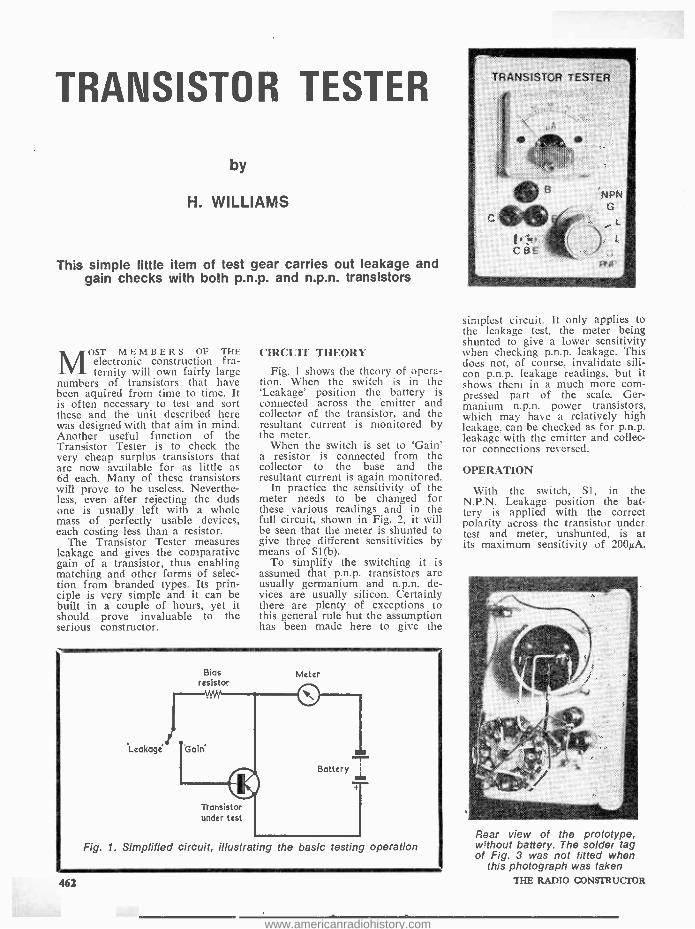
This simple little item of test gear carries out leakage and gain checks with both p.n.p. and n.p.n. transistors
MOST MEMBERS OF THE electronic construction fra- ternity will own fairly large
numbers of transistors that have been aquired from time to time. It is often necessary to test and sort these and the unit described here was designed with that aim in mind. Another useful function of the Transistor Tester is to check the very cheap surplus transistors that are now available for as little as 6d each. Many of these transistors will prove to be useless. Neverthe- less, even after rejecting the duds one is usually left with a whole mass of perfectly usable devices, each costing less than a resistor.
The Transistor Tester measures leakage and gives the comparative gain of a transistor, thus enabling matching and other forms of selec- tion from branded types. Its prin- ciple is very simple and it can be built in a couple of hours, yet it should prove invaluable to the serious constructor.
CIRCUIT THEORY
Fig. 1 shows the theory of opera- tion. When the switch is in the `Leakage' position the battery is connected across the emitter and collector of the transistor, and the resultant current is monitored by the meter.
When the switch is set to `Gain a resistor is connected from the collector to the base and the resultant current is again monitored.
In practice the sensitivity of the meter needs to be changed for these various readings and in the full circuit, shown in Fig. 2, it will be seen that the meter is shunted to give three different sensitivities by means of Sl(b).
To simplify the switching it is assumed that p.n.p. transistors are usually germanium and n.p.n. de- vices are usually silicon. Certainly there are plenty of exceptions to this general rule but the assumption has been made here to give the
Bias resistor
Meter
Transistor under test
Fig. 1. Simplified circuit, Illustrating the basic testing operation
462
simplest circuit. It only applies to the leakage test, the meter being shunted to give a lower sensitivity when checking p.n.p. leakage. This does not, of course, invalidate sili- con p.n.p. leakage readings, but it shows them in a much more com- pressed part of the scale. Ger- manium n.p.n. power transistors, which may have a relatively high leakage, can be checked as for p.n.p. leakage with the emitter and collec- tor connections reversed.
OPERATION
With the switch, Sl, in the N.P.N. Leakage position the bat- tery is applied with the correct polarity across the transistor under test and meter, unshunted, is at its maximum sensitivity of 200µA.
Rear view of the prototype, w7thout battery. The solder tag of Fig. 3 was not fitted when
this photograph was taken THE RADIO CONSTRUCTOR
www.americanradiohistory.com
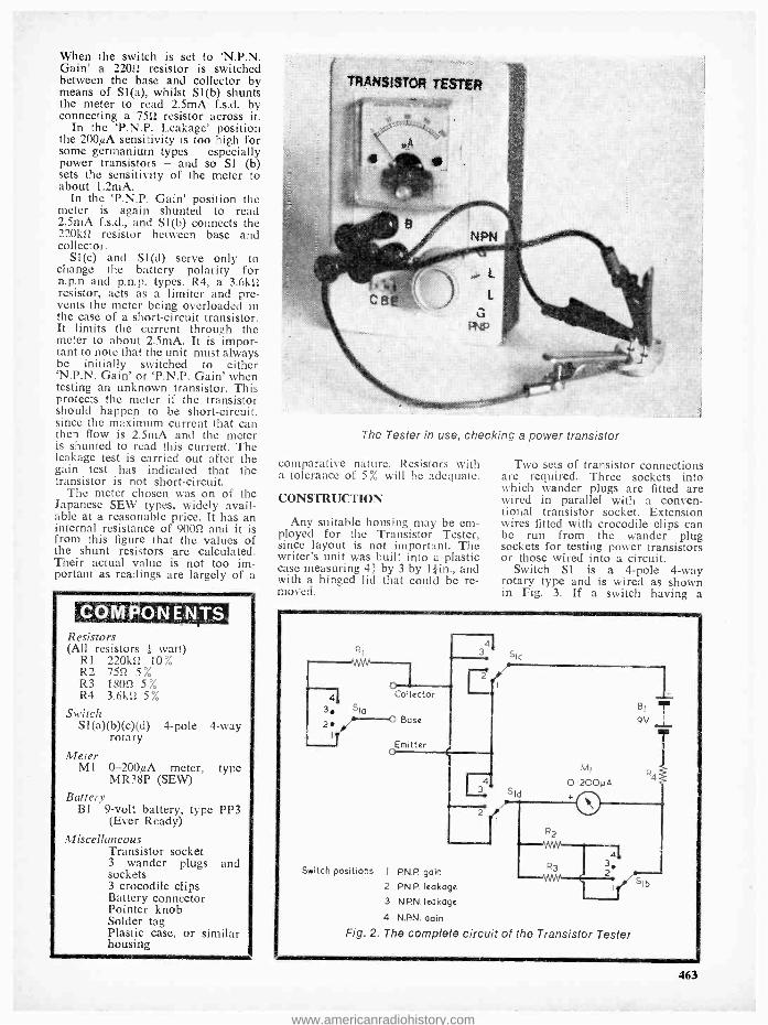
When the switch is set to `N.P.N. Gain' a 22052 resistor is switched between the base and collector by means of SI(a), whilst Sl(b) shunts the meter to read 2.5mA f.s.d. by connecting a 7552 resistor across it.
In the 'P.N.P. Leakage' position the 200µA sensitivity is too high for some germanium types - especially power transistors - and so Si (b) sets the sensitivity of the meter to about 1.2mA.
In the `P.N.P. Gain' position the meter is again shunted to read 2.5mA f.s.d., and Sl(b) connects the 220k12 resistor between base and collector.
SI(c) and S1(d) serve only to change the battery polarity for n.p.n and p.n.p. types. R4, a 3.6k52 resistor, acts as a limiter and pre- vents the meter being overloaded in the case of a short -circuit transistor. It limits the current through the meter to about 2.5mA. It is impor- tant to note that the unit must always be initially switched to either 'N.P.N. Gain' or `P.N.P. Gain' when testing an unknown transistor. This protects the meter if the transistor should happen to be short -circuit, since the maximum current that can then flow is 2.5mA and the meter is shunted to read this current. The leakage test is carried out after the gain test has indicated that the transistor is not short -circuit.
The meter chosen was on of the Japanese SEW types, widely avail- able at a reasonable price. It has an internal resistance of 90052 and it is from this figure that the values of the shunt resistors are calculated. Their actual value is not too im- portant as readings are largely of a
COM PON ENTS Resistors (All resistors ; watt)
RI 220102 10% R2 7552 5% R3 18051 5% R4 3.6k52 5%
Switch SI (a)(b)(c)(d) 4 -pole 4 -way
rotary Meter
MI 0 -200µA meter, type MR38P (SEW)
Battery 131 9 -volt battery, type PP3
(Ever Ready) Miscellaneous
Transistor socket 3 wander plugs and sockets 3 crocodile clips Battery connector Pointer knob Solder tag Plastic case, or similar housing
TRANSISTOR TESTER
The Tester in use, checking a power transistor
comparative nature. Resistors with a tolerance of 5% will be adequate.
CONSTRUCTION
Any suitable housing may be em- ployed for the Transistor Tester, since layout is not important. The writer's unit was built into a plastic case measuring 4+ by 3 by l;in., and with a hinged lid that could be re- moved.
Two sets of transistor connections are required. Three sockets into which wander plugs are fitted are wired in parallel with a conven- tional transistor socket. Extension wires fitted with crocodile clips can be run from the wander plug sockets for testing power transistors or those wired into a circuit.
Switch SI is a 4 -pole 4 -way rotary type and is wired as shown in Fig. 3. If a switch having a
4j 3 SIG
o Collector
2 Base
© miller
al 3 Sic
4
2? 51d
MI
0-200yA + O
BI 9V
R4
4
Switch positions I P.N.P. gain
2 P.N.P. leakage
3 N.P.N. leakage
4 N.N. Dain
Fig. 2. The complete circuit of the Transistor Tester
1111
51b
463
www.americanradiohistory.com

different construction is employed. wiring should follow the circuit diagram of Fig. 2. The switch must have break -before -make contacts.
OPERATION
When the Transistor Tester has been built, carefully check all wiring for errors. Set Sl to either position I or IV and quickly short -circuit the collector and emitter sockets. The meter should read near full -scale deflection.
Calibration, if required, is best carried out with transistors which are known to be good; one will quickly get to know what the cor- rect or acceptable readings are and a note can be made on a table affixed to the case of the unit. Short -circuit transistors will, as al- ready stated, show f.s.d., and open - circuit devices will show no reading at all.
An interesting exercise is to mea- sure some of the surplus `equivalent' transistors against the `real McCoy'. Frequently the differences will be- come apparent, but the author has come across several instances where differences failed to show up on the tester. Also, the transistors, when in circuit, offered identical perfor- mances.
Fig. 3. Construction and wiring diagram when a double bank single wafer switch is used. The contacts shown in broken line are below the wafer. Use a continuity tester to identify individual contacts if any doubt exists. The components should be mounted on a plastic case lid, as in the prototype, or on a front panel made
of Paxolin or similar insulating material
NEW LOGIC PROBE A versatile 5 -volt logic probe,
designed for testing DTL and TTL circuitry, has been introduced by EMI Electronics' Radar and Equip- ment Division, Hayes, Middlesex. Designated `LP500 /1', the new probe can identify seven different cate- gories of logic signal including the important open circuit condition. These capabilities allow rapid checking of logic circuits thereby minimising the need for expensive test equipment such as oscilloscopes.
The 18cm (7in.) long, 1.9 cm (0.75in.) diameter probe distingui- shes between logic 1, logic 0, open circuit, +ve going pulses, -ve going pulses, square waves below 1MHz (approx.) and pulse trains (including square waves) with a p.r.f. above 1MHz (approx.). It can be run from the power supply of the equipment under test, from a 4.5 Volt battery or a standard bench power supply. Connection to the supply is effected by a 120cm (4ft.) cable terminated in 4mm banana plugs which afford simple connection to many stan- dard bench supplies. Insulated plug - on crocodile clips provide easy alternative connection.
LOGIC PROBE - METHOD OF OPERATION
The probe operates in one of two modes selected by a thumb- opera- ted microswitch. With the switch
464
depressed, the a.c. mode is indi- cated by a steady light under open circuit conditions. When the switch is released, the d.c. mode is indi- cated by a flashing light in the open circuit condition.
In the d.c. mode, the probe sen- ses the input and gives an `off', `on' or flashing indication according to whether the input level is below, above or between two voltage thresholds; VI: 0.625V ±0.125V or V2: 2.4V ±0.4V. If any waveform
is present it is integrated over 100mS and the mean level sensed.
In the a.c. mode the probe re- sponds to positive going edges faster than 0.5 µs, each edge caus- ing the lamp to extinguish and then re-light after 100mS. Single pulses as narrow as 50nS and pulse trains having p.r.f.'s up to 1 MHz (approx.) are detected in this manner. Pulses at p.r.f.'s greater than 1 MHz (approx.) are indi- cated by an `off' condition.
THE RADIO CONSTRUCTOR
www.americanradiohistory.com
Timer Without Electrolytics by
J. PHILIPS
In order to obtain sufficiently long timing periods the current trend in electronic timers is to employ an electrolytic component as the timing capacitor. This article describes a timing circuit which, by taking advantage of a pulsed transistor, enables a paper or plastic foil capacitor to be used
instead
NUMBER OF CIRCUITS FOR ELECTRONIC TIMERS Ahave appeared in this and other journals over
recent years, all of the published designs taking advantage of a standard technique in which the volt- age across a charging or discharging capacitor triggers a switching circuit when It reaches a prede- termined level. To obtain reasonably long timing periods with this technique it is necessary to employ capacitors having large values, whereupon the inevit- able choice has consisted of electrolytic components. Unfortunately, timer designs of this nature can never be looked upon as providing the ultimate in accuracy. This is due to the well-known shortcomings of elec- trolytic capacitors, these consisting of variations in capacitance with age and applied voltage, and varia- tions in leakage resistance due to age, applied voltage and temperature.
This article describes a different and unusual approach to the design of the electronic timer, and the circuit to be discussed enables long timing periods to be achieved with a timing capacitor having a rela- tively low value. There is no necessity to use an electrolytic component, and the timing capacitor can be a standard paper or plastic foil type instead. In consequence, the resultant design is completely free from the inherant unreliability that is given when an electrolytic timing capacitor is employed.
DISCHARGING CIRCUIT
Before examining the overall circuit of the timer it will be of advantage to initially discuss the reason why it allows a low value timing capacitor to be employed.
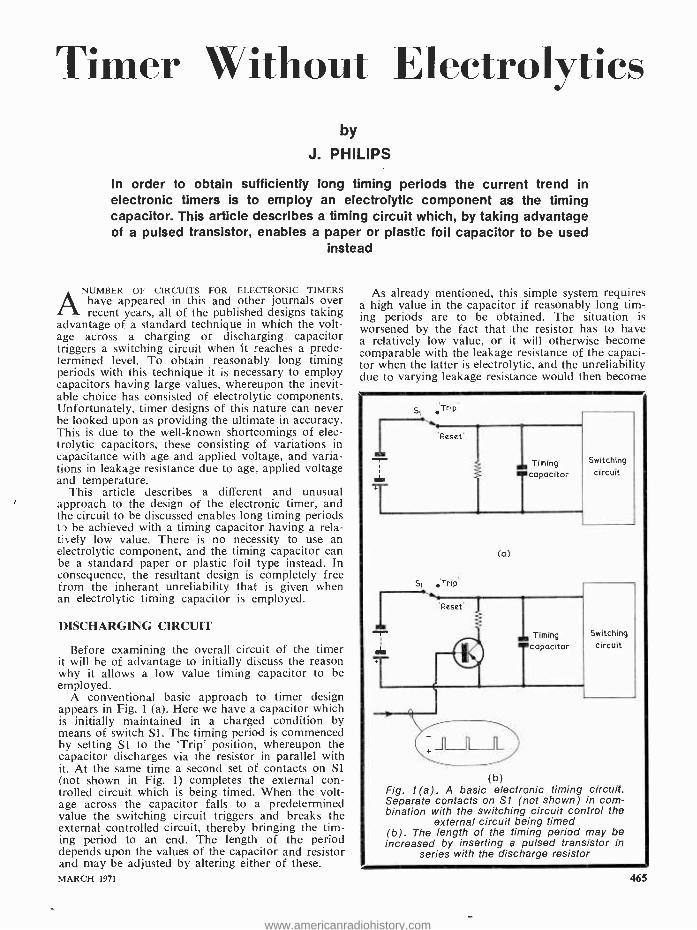
A conventional basic approach to timer design appears in Fig. 1 (a). Here we have a capacitor which is initially maintained in a charged condition by means of switch Sl. The timing period is commenced by setting SI to the `Trip' position, whereupon the capacitor discharges via the resistor in parallel with it. At the same time a second set of contacts on S1 (not shown in Fig. 1) completes the external con- trolled circuit which is being timed. When the volt- age across the capacitor falls to a predetermined value the switching circuit triggers and breaks the external controlled circuit, thereby bringing the tim- ing period to an end. The length of the period depends upon the values of the capacitor and resistor and may be adjusted by altering either of these. MARCH 1971
As already mentioned, this simple system requires a high value in the capacitor if reasonably long tim- ing periods are to be obtained. The situation is worsened by the fact that the resistor has to have a relatively low value, or it will otherwise become comparable with the leakage resistance of the capaci- tor when the latter is electrolytic, and the unreliability due to varying leakage resistance would then become
1 T
Si Trip
'Reset
Si ,Trip
Timing capacitor
(a)
Switching circuit
(b) Fig. 1(a). A basic electronic timing circuit. Separate contacts on S1 (not shown) in com- bination with the switching circuit control the
external circuit being timed (b). The length of the timing period may be increased by inserting a pulsed transistor in
series with the discharge resistor
465
www.americanradiohistory.com

more evident. A low value in the resistor necessitates, again, a correspondingly high value in the capacitor.
The solution proposed in the author's design is shown diagrammatically in Fig. 1 (b). This circuit is operated in the same manner as that of Fig. 1(a), but a transistor is now inserted in series at the lower end of the resistor. A series of pulses is fed to the base of the transistor, with the result that it only passes current during the presence of each pulse, and is cut -off between pulses. If the capacitor and resistor have the same values as they have in Fig. 1(a), the capacitor discharges more slowly because the discharge current now only flows during pulses. Should the pulses be of much shorter dura- tion than the intervals between pulses, the discharge period of the capacitor will be considerably extended. Alternatively, the value of the capacitor can be made very much smaller for the same discharge period.
If, for reasonably long discharge periods the value of the capacitor is sufficiently low to enable a non - electrolytic component to be economically employed, a further advantage accrues. A good quality non - electrolytic capacitor (i.e. a paper or plastic foil com- ponent) can have an extremely high leakage resist- ance, this being particularly true of the plastic types. A typical specification for polycarbonate capacitors, for instance, quotes insulation resistance in megohms multiplied by microfarads as being greater than 20,000. With insulation resistances as high as this it becomes possible to use larger values of discharge
resistor in the timing circuit, whereupon the value required in the capacitor becomes lower again.
Both these techniques - the use of a pulsed tran- sistor in series with the discharge resistor and a high value discharge resistor across a paper or plastic foil capacitor - are employed in the timing circuit now to be described.
THE CIRCUIT
The complete circuit of the electronic timer appears in Fig. 2. In this diagram, the timing capaci- tor is C3 and the pulsed transistor is TR3, this being a p.n.p. silicon junction transistor type 0C204. It is pulsed by inserting its base -emitter junction in series with the emitter of TR2 which, with TR1, is in a multivibrator circuit. When TR2 is turned on during the multivibrator cycle so also is TR3, which then draws current from C3 via R6 and R7. R7 provides a control of timing period which, with the author's circuit, ranges from 2 to 110 seconds.
In the multivibrator, the period during which TR2 is turned off is controlled by R3 and C2, whilst the period when TR1 is turned off is controlled by R2 and Cl. The product of the values of R3 and C2 is 50 times the product of the values of R2 and Cl, whereupon it would appear at first sight that the period of turn -off in TR2 during each cycle will be 50 times greater than the period of turn -off in TR 1. For the present application we are more interested
466
RLA1 R'
T ?eSla
IS Slb
To controlled
16 circuit S2o
11
S2b -9v On -Off
- c ACY 19
Lead -outs
dot
OC 204 Lead -outs
000 bce
BC 169C
Lead -outs
S 1
positions : R - reset .T'- trip
Fig. 2. The complete circuit of the electronic timer. The timing capacitor, C3, is paper plastic foil, and is not electrolytic
or
MS RADIO CONSTRUCTOR
www.americanradiohistory.com

in the length of time when TR2, and hence TR3, is turned on, and our first -sight appreciation would indicate that TR2 and TR3 are turned on for only one fifty -first fraction of each multivibrator cycle. In practice, unfortunately, it is rather difficult to obtain a high on -off time ratio from a simple 2- transistor multivibrator. In the present circuit, for example, TR2 commences to pass current for a short period before the transition which turns it fully on, this being due to the slow increase in potential at its base resulting from the large values in C2 and R3. Thus, TR2 is already passing a small but significant current by the time that the positive excursion at its collector becomes sufficiently swift to initiate the changeover by way of the relatively low value capaci- tor Cl. Because of this effect, the period during which the pulsed transistor. TR3, is at least partly conduc- tive becomes longer than one fifty -first of the multivi- brator cycle. Measurements taken with the author's unit showed an average current flow in R6, with R7 slider at the lower end of its track, which was about one -twentieth of the current which flowed if the collector of TR3 was short- circuited to its emitter. With R7 slider at the upper end of its track the fraction was approximately one -fifteenth, the variation being presumably due to the lower current which was then drawn through TR3. The result is that the pulsed transistor circuit enables the timing capacitor to have one -fifteenth to one -twentieth the value it would otherwise require. This is still a con- siderable advantage and well justifies the use of the multivibrator and pulsed transistor.
It is appreciated that a more complex multivibrator circuit would provide a cleaner rectangular wave for application to the pulsed transistor. However, the very simple circuit, as shown, gave excellent practical results and was quite reliable from the point of view of repeatability of timing periods. In consequence, there seemed to be little point in adding further components and devices to it when it was already functioning adequately.
Before leaving this section of the circuit, brief mention should be made of resistor R5. This com- ponent is included merely to ensure that leakage current in TR2 when it is turned off does not cause the base of TR3 to rise above its 0.6 volt turn -on potential. It was found that the average collector current in TR3 reduced slightly when R5 was added. The presence of R5 has negligible effect on the pulsing function, in which TR2 commences to draw current before it turns fully on. Indeed, the average current in TR3 collector circuit remained unaltered for experimental variations in R5 from 1 to 3.9kS2.
SWITCHING CIRCUIT
We have, up to now, concentrated solely on the multivibrator and pulsed transistor section of the timing circuit since this represents the novel variation on standard timer design which provides the main reason for this article. We can next examine the rest of the circuit, armed with the knowledge that C3 is the paper or plastic foil timing capacitor and that its rate of discharge, and hence the length of the timing period, is controlled by R7.
In the remainder of the circuit, switch Si is norm- ally kept in the `Reset' position, whereupon its con- tacts S1(b) connect the upper plate of C3 to the MARCH 1971
COMPONENTS Resistors
(All fixed values ; watt 10 %) R1 2.2kS2 R2 471x2 R3 100k[2 R4 2.2kS2 R5 2.2kg2 R6 10k12 R7 2MS2 potentiometer, linear R8 1052 R9 4.7k12
Capacitors Cl 0.01µF, paper or plastic foil C2 0.25µF, paper or plastic foil C3 8µF, paper or plastic foil
Semiconductors TRI ACY19 TR2 ACY19 TR3 0C204 TR4 BC169C TR5 ACY19 D1 DD000 D2 DD000 D3 DD000
Switches Si d.p.d.t., toggle S2 d.p.d.t., toggle or rotary
Relay RLA1 See text
negative 18 volt line via limiter resistor R8. Under these circumstances, C3 is charged to 18 volts. Since the upper plate of C3 is negative of the 9 volt supply line, silicon diode Dl is reverse -biased and no cur- rent can flow through it to the relay switching tran- sistors TR4 and TR5. Relay RLA /1 is, in con- sequence, de- energised. At the same time, the connec- tions to the controlled circuit are kept open by contacts S1(a) of switch Si.
-W
Short - circuit for test
Fig. 3. A simple test circuit for cHecking the multivibrator and pulsing circuits
467
www.americanradiohistory.com

To initiate a timing period, Si is set to the `Trip' position, whereupon its contacts S1(a) complete the external controlled circuit. Also, its contacts Sl(b) break the 18 volt supply to the upper plate of C3, which now begins to discharge via R7, R6 and pulsed transistor TR3. After a period, the potential on the upper plate of C3 falls below that on the 9 volt supply line, whereupon diode D1 conducts and allows current to flow via limiter resistor R9 to the base of TR4. TR4 and TR5 form a direct -coupled pair having extremely high current gain, and represent a combination which has been used recently in several of the `Suggested Circuit' articles by G. A. French. They function very well in the present circuit, their gain being such that a base current in TR4 of the order of 2µA is all that is required to cause the relay in the emitter circuit of TR5 to become ener- gised. When the relay energises, its break contacts RLA1 open and interrupt the external controlled circuit.
The timing period is now complete. A further period may be initiated by putting Si to `Reset', whereupon C3 becomes charged again and the relay releases, and then setting it once more to `Trip'.
Two components which have not so far been men- tioned are silicon diodes D2 and D3. The function of D2 is to ensure that leakage current in DI cannot cause the reverse emitter -base voltage in TR4 to exceed about 0.6 volts when the upper plate of C3 is negative of the 9 volt supply line. The maximum reverse base -emitter voltage quoted for the transistor specified for TR4 is 5 volts only. Silicon diode D3 is the usual component which is connected across transistor- driven relay coils, and it prevents the appearance of high back- e.m.f. voltages when the relay de- energises.
COMPONENTS
The transistors specified are all readily obtainable types. The BC169C in the TR4 position is available from Amatronix Ltd. Diodes Dl to D3 are not critical and any silicon diode can be employed instead of the Lucas DD000 type indicated in the Com- ponents List.
Sl is a d.p.d.t. toggle switch. A rotary type is not advised here. On the other hand, S2 can be any type of d.p.d.t. switch.
Relay RLA1 is any relay whose coil resistance is 40012 or greater, and which energises reliably at 9 volts. The writer employed a P.0.3000 relay with a 60052 coil in the protoype circuit. It requires a single break contact set only, and suitable relays are available from a number of suppliers. In addi- tion, P.0.3000 relays, made up to customers' require- ments can be obtained from L. Wilkinson (Croydon) Ltd., Longley House, Longley Road, West Cryodon, Surrey.
If the constructor wishes to employ a larger non - electrolytic capacitor in the C3 position this is, of course, perfectly in order. The values of R7 and R6 could then be scaled down accordingly. Thus, if C3 is made 16µF, R7 and R6 can be 1MS2 and 5k52 respectively. The larger capacitor will enable a possibly slightly more robust potentiometer to be used in the R7 position, but should otherwise offer no particular advantage. As stated earlier, the timing range obtained with the author's unit was 2 to 110 seconds, but there may be variations from these 468
figures with other units built up to the circuit. If necessary, a little extra at the longer end of the range can be obtained by slightly increasing the value of C3. Resistor R7 should be fitted with a pointer knob and a scale calibrated in the timing periods it pro- vides. Four or five measured calibration points will need to be taken when drawing up this scale, as it will be somewhat non -linear.
R10
Silicon rectifier
-18V
ADISI
9 -0 -9V secondary
On-Off
E A.C.
mains -9V
18v 250mW Zener diode
200 NF
12V
wkg.
Silicon rectifier
200 NF
25V wkg
Mains transformer
kll
9IV 250mW Zener diode
R10.11 - see text e
c
AD 161
Fig. 4. A suggested power supply circuit for the timer. The AD161 transistor need not be
mounted on a heat sink
Probably the only part of the circuit where the constructor could possibly encounter trouble is in the multivibrator incorporating TRI and TR2. High -gain transistors are essential here. The author checked a number of ACY19's in this part of the circuit and all worked correctly, but there is still a very slight risk that a pair of particularly low gain devices may not oscillate. Should this occur, the only solution is to reduce the value of R3 and /or C2 until oscilla- tion commences, thereby sacrificing a little of the pulse ratio advantage offered by the multivibrator. Indeed, a good constructional approach consists of getting the multivibrator and TR3 in working order before attending to the rest of the circuit. The operation of TR3 can be checked by connecting a 1 kI2 resistor between its collector and the 9 volt supply line with a current- reading meter in series, as in Fig. 3. The current should be about 9mA when the collector of TR3 is short- circuited to its emitter. If the current drops by a considerable amount but does not cease altogether when the short- circuit is taken off, then the multivibrator is working and the circuit is pulsing. After this test, the 1kS2 resistor may be removed, R6 and R7 connected to the collec- tor of TR3 and the remainder of the timer made up.
Whilst dealing with the components an interesting final point is that, at the end of the timing period, capacitor C3 also acts as an integrating device which enables the relay to energise. If, during tests, an attempt is made to energise the relay without C3 in circuit all that happens is that amplified pulses are
THE RADIO CONSTRUCTOR
www.americanradiohistory.com
applied to the relay coil. The relay does not then energise because the coil presents a high inductive reactance to these pulses!
POWER SUPPLY
The current taken from its power supply by the timer is low, and the author's unit drew 6mA from the 9 volt negative line with the relay de- energised and 23mA when the relay operated. The current drawn from the 18 volt line is negligibly low, con- sisting merely of that required to charge capacitor C3.
The writer employed bench stabilised supplies to provide the two voltages, and it is assumed that a constructor who intends to make up the unit will have sufficient technical knowledge to be able to design a simple power supply. A suggested supply circuit, which has not been checked by the author in practice, is given in Fig. 4. The operation of this supply is self -explanatory, and doubtless readers will be able to make up alternative supplies which offer the same performance and which employ components that are already to hand.
So far as voltage regulation is concerned it should be noted that the 9 volt supply need only be well - regulated for the circuit condition in which the relay is de- energised. It does not matter if the supply voltage falls slightly when the relay energises. The 18 volt supply will be adequately regulated by a simple zener diode circuit. If the circuit of Fig. 4 is made up, both R10 and R11 should have values which cause zener diode current, as measured by a meter temporarily inserted in series with each diode, to be of the order of 10mA. Also, S2 of Fig. 2
is not required since the timer can be switched on and off by the switch in Fig. 4.
TRUE R.M.S. VOLTMETER
The VX408A true r.m.s. voltmeter, which is now available from ITT Components Group Europe, can display accurately the average voltage or the true r.ms. voltage of circuits under test as required. This facility is particularly important when studying transitory signals.
Main features of the VX408A are the high input impedance, and low noise factor preamplifier with attenuator. A high gain amplifier allowing wide ex-
cursion of the output signal amplitude provides a large peak factor range when measuring r.m.s volt- ages.
Made by ITT Metrix, the VX408A has an input impedance of 10 megohm with voltage range up to 300mV and 300V. Band widths are 10Hz to 10MHz for average voltages and 50Hz to 10MHz for r.m.s. voltages.
For further information contact ITT Electronic Services, Edinburgh Way, Harlow, Essex - telephone: Harlow (02796) 26811, ext. 790; telex: 81146. MARCH 1971
RADIO CONSTRUCTOR
APRIL ISSUE
THE `TRI -BAND RANGER' TRANS- MITTER, PART 1
Covering the 40, 80 and 160 metre bands, this transmitter offers c.w. and phone at power outputs of 10 and 7 watts respectively. It has an integral power supply but provision is made for powering from an external supply. Further advantages are simplicity of operation, small size and the ability to match into a wide range of aerials.
D.C. AND AUDIO LCR BRIDGE A comprehensive design which provides a
wide range of measurements of inductance, capacitance and resistance.
MODIFYING THE `TRIO' 9R -59DE RECEIVER, PART 2
In this concluding article, the author des- cribes the inclusion of an EF183 high gain r.f. stage, an added double -tuned i.f. stage, curing frequency drift above 15MHz and provides r.f. alignment details.
PLUS A MANY OTHER CON-
STRUCTIONAL PROJECTS
DATA SHEET 49 (P.N.P. TRANSISTOR LEAD -CUTSI
® SUPPORTING FEATURES
ON SALE APRIL 1st
469
www.americanradiohistory.com

T HE VISUAL BELL INDICATOR circuit described in this month's article is the result of a re-
quest from a reader, who asked for a transistor circuit which would cause a bulb to light up whenever an electric bell was rung. A further requirement was that the bulb should remain illuminated for some four or five seconds after the bell ceased ringing.
Since there are quite a number of applications for a device of this nature, it was considered that the circuitry involved would make a worthwhile subject for the 'Suggest- ed Circuit' series. An obvious appli- cation that springs to mind is the installation of the bulb in the living - room, so that the family, whilst watching television, can be warned that the front door bell is ringing or has just been rung. Again, since the system can be adapted for more than one bell -push, it becomes possible to fit a number of bulbs on an in- dicator board, each bulb correspon- ding to an individual bell -push. The bulbs will then indicate which bell - push has been pressed, the associ- ated bulb remaining illuminated even after the bell has stopped ringing.
CIRCUIT OPERATION
The circuit which was evolved is shown in Fig. 1, this diagram apply- ing to the situation where there is one bell -push only. The system is powered by a standard bell trans- former having an eight volt second- ary. The primary of this transformer connects permanently to the mains supply, and the eight volts appear- ing on its secondary is rectified by D2, causing a d.c. voltage to be continually available across C3. 470
When the bell -push is pressed, it completes a circuit from the bell transformer secondary to the bell via resistor R1, whereupon a small alternating voltage is dropped across this resistor. The voltage is rectified by diode D1, with the result that capacitor Cl charges up to a voltage lying between 1 and 1.5 volts. Due to the voltage across Cl, base current flows in transistor TR1 which, with TR2, forms a Darling- ton pair. TR2 bottoms and pilot lamp PLl becomes illuminated, the current flowing through it being obtained from the rectified supply across C3.
As soon as the bell -push is re- leased no further current is drawn through R1, and the voltage across this resistor drops to zero. Capacitor Cl is still charged, and it now com- mences to discharge via R2 into R3 and into the base -emitter junctions of TR1 and TR2. No discharge current flows via D1, which is now reversed -biased. The base current in TR1 slowly decreases. However, the amplified current in the base - emitter junction of TR2 is still sufficient to maintain this transistor in the bottomed condition for ap- proximately three seconds. After this period, the collector current in
Bell 2 transformer
Bell -push
c
ACY 19
Fig. 1. Circuit of the visual bell indicator. The bulb continues to glow for a short period after the bell -push has been released
RI,01,D2 - see text
Bell
THE RADIO CONSTRUCTOR
www.americanradiohistory.com

TR2 commences to fall and the pilot lamp illumination drops until it becomes completely extinguished. The lamp will then light up again when the bell -push is pressed once more, and will similarly remain illuminated for a short period after the bell -push has been released.
FURTHER DETAILS
There are a number of points in the circuit which have not been covered by the explanation of cir- cuit operation just given. To begin with, both TR1 and TR2 need to be germanium types, as specified, because silicon transistors would exhibit a higher base -emitter for- ward voltage drop, with the conse- quence that it would be necessary to drop a much higher voltage across R1 to cause TR2 to bottom. The higher voltage dropped across this resistor might then adversely affect bell operation, this being particularly true if there are long wiring runs to the bell -push. Since TRI and TR2 are germanium de- vices, their use in the Darlington configuration causes a small, but significant, leakage current to appear in TR2 when the bell -push is not
pressed. This continual leakage current prohibits the use of a battery for powering the light cir- cuit, because the battery would be- come exhausted too rapidly. At the same time, the light circuit cannot be powered by unrectified a.c. (say, from a second bell transformer) because, although TR2 could pass sufficient current on alternate half - cycles to illuminate the lamp, the collector -base junction of TR1 would conduct on half -cycles when the collector was positive and cause a partial discharge in Cl. Cl would not, then, remain charged for a sufficiently long period after the bell -push had been released.
All these factors point to the use of a rectified voltage from the bell transformer which supplies the bell itself. In this case, precautions have to be taken to protect the transistors from the voltage `spikes' which can appear in an electric bell circuit. A small level of protection is given by C3 but the main protection is pro- vided by C2. In company with the resistance offered by PL1, this com- ponent provides a decoupling circuit for any `spikes' which may be pre- sent across C3. The base -emitter junctions of TRI and TR2 are auto-
r" push
o
DI
CI
RI
R2
TRI
PLI D2
TR2
IrC2 o 3-4
D3
C4 400m pF 4V wkg
SW?
5 22kn
TR3 ACY 19
R6
IOkn TR4
ACY 19
R4
PL2 6V 6OmA 0
C5
ow
j5V
SOpF
wkg
R4,D3 -see text
Fig. 2. The circuit can be employed to indicate which of a number of bell -pushes has been pressed, and this diagram shows a system having two bell- pushes and two indicator bulbs. The components
in the upper section have the same values as in Fig. 1
Bell
A.C.
mains
MARCH 1971
AUDIO
AMPLIFIERS
16 Transistor & Valve Designs for the Home Constructor
Amplifiers for Tuner Units, Record Players,
Tape Recorders, Public Address, etc., etc.
Includes contributions by such well -known authors as
A. S. Carpenter, A. Kinloch, E. Govier, G. A. French, F. G. Rayer, P. F. Bretherick, K. Jones, D. Aldous, R. Murray -Shelley, C. Swires, G. A. Stevens and V. E. Holley.
Edited by J. R. Davies
124 pages
PRICE 53p Postage 5?,p
MEN I MIEN I MIN
To. DATA PUBLICATIONS Ltd., 57 Maida Vale London W9
Please supply copy(ies) of "Audio Amplifiers ", Data Book No. 18. I enclose cheque/
crossed postal order for
Name
Address
RC BLOCK LETTERS PLEASE
471
www.americanradiohistory.com

matically protected by Cl and R2. Rectifier D1 can be any silicon
rectifier in the Lucas DD000 cate- gory. It would be advisable to use a high voltage rectifier for D2. The reverse voltages applied to this com- ponent during bell operation may, in some instances, be quite high and a suitable component would be a BYI00. In practice the reverse volt- ages will very probably be con- siderably lower than those at which this rectifier is rated but, since the BY100 is a low -cost component in any case, and since it functions as well, at low voltages, as a low volt- age rectifier, its choice would be justified.
The only remaining component which has not been mentioned is R3. The purpose of this resistor is to reduce leakage current in the Darlington pair of transistors when the bell -push is not pressed, and it has a value which causes the fila- ment of the pilot lamp to be just below glowing level.
If there are more than one bell - push, the circuit to the left of diode D2 can be duplicated. A system with two bell -pushes, intended for operation with a single bell trans- former and bell, is given in Fig. 2. The section which includes the second bell -push, D3, TR3, TR4, R4 to R6, C4, C5 and PL2 is iden- tical with that having the similar components in Fig. I. R4 has the same value as R1, and D3 is the same type as Dl.
When Bell -Push 2 is pressed, a voltage is dropped across R4, whereupon C4 becomes charged in the same way as did Cl of Fig. 1.
Transistors TR3 and TR4 then cause PL2 to light up, and remain
illuminated for a short period after Bell -Push 2 has been released, in a similar manner as did TRI and TR2.
If further bell- pushes are incor- porated in the system further sec- tions may be added, these running from the single bell transformer, and from the single rectified voltage provided by D2.
COMPONENTS
The components employed in the circuit are standard types, and the diodes have already been dealt with. Resistors R2 and R3 (and R5 and R6 in Fig. 2) are 10% 1 watt com- ponents. The 6 -volt 60mA bulb (or bulbs) is available from Home Radio under Cat. No. PL7. It is desirable that the transistors speci- fied be employed. Alternatives of similar gain can be used, but they must have equal, or higher, voltage and current ratings.
The bell transformer employed by the author was an inexpensive com- ponent retailed by Woolworth's stores, and it has a 5 -volt tap in its 8 -volt secondary winding. Bell transformers offering less than eight volts will not be satisfactory in the circuit. If the bell transformer offers more than eight volts, resis- tance should be inserted in series with D2 at the point marked with a cross in Figs. 1 and 2. The resis- tance should be of the order of 1651 for every volt in excess of eight volts. In Figs. 1 and 2, the terminal of the bell which does not connect to the bell -push is wired to the upper end of T1 secondary. It will not upset operation of the transistor circuitry if this terminal of the bell is connected to a tap in the second-
ary instead, since the bell current will still flow through R1 (or R4). It may be found that some low -cost 'bells function better at a lower supply voltage.
The value of R1 is found experi- mentally, and should be that which causes a rectified voltage of 1 to 1.5 volts to appear across Cl when the bell -push is pressed. The value will probably be of the order of 3 to 552. Take care not to fit too high a value of resistor initially, or the rectified voltage across Cl may exceed its working voltage rating. The resistor finally employed should be rated at one watt.
If a good quality bell is employed, the circuit should operate reliably as described, but some difficulty may be experienced with inexpen- sive electric bells which draw a
heavy operating current. In most instances it will be found helpful to run such bells from a low voltage tapping, as already described. Alter- natively, a small -value resistor may be inserted directly in series with the bell to reduce its current con- sumption. If the bell draws a heavy current, the indicating bulb will run at reduced brilliance when the bell -push is pressed, and will then brighten when the bell -push is re- leased.
The components in the circuit may be assembled in a small unit near the bell transformer. Capacitor C2 (and C5 in Fig. 2) should be mounted close to TR2 (or TR4 in Fig. 2). If it is found that the bulb continually glows at low level when the associated bell -push is not pressed, the value of R3 (or R6 in Fig. 2) should be reduced until the effect clears.
EXPANSION OF ITA UHF SERVICE The Independent Television Authority announces
the award to the Marconi Company of a contract worth more than £1- million. This contract is for the supply of television transmitters needed for the ex- pansion of the ITA network of UHF main stations.
The contract covers the supply of 15 sets of trans- mitters for installation in different regions of the United Kingdom from 1972 onwards. All these equipments, each rated at up to 12kW output, will be installed at main ITA stations to be built as part of the second phase of the UHF Network of trans- mitters being constructed to provide a duplicated UHF 625 -line combined colour and black- and -white service.
The award of this contract to the Marconi Com- pany follows detailed assessment of tenders from a number of British and overseas firms. It is the usual practice of the ITA to standardise whenever possible on a single manufacturer for a complete series of stations: 26 of the 27 main transmitting stations now in operation or being built in the first phase of this Network are from Pye of Cambridge. The ITA has paid tribute to the equipment supplied by Pye, and their success in meeting the stringent delivery dates
472
under the terms of a contract worth more than £2- million placed with the company in 1967.
Among the technical features of the second phase stations now being investigated by the Marconi Company is the use of five -cavity klystrons of the type pioneered in Europe by the ITA since 1969. All the transmitters will be operated at unattended stations by means of automatic or remote -control.
Each station will have three klystron amplifiers: in normal operation, the vision and sound outputs will be derived from separate amplifiers; the third klystron will form a reduced -power, standby unit, providing combined vision and sound output. Should a fault occur in the main units, the standby unit will be brought rapidly into operation, either automati- cally or by remote control from one of the 14 ITA regional colour control centres. This will enable the service to be maintained at a power of only 6dB below normal level.
The sites at which these transmitters are to be in- stalled will be announced later. They will extend the coverage in a number of regions in which one or more main transmitting stations have already been included in the first phase of the ITA UHF network building programme.
THE RADIO CONSTRUCTOR
www.americanradiohistory.com

Sequential Latching Relay
Circuit
by
R. A. BUTTERWORTH, G8BI
A simple combination of three relays enables circuits to be switched on, then off, by sequen-
tial closures of a push -button
AREADY MADE SEQUENTIAL LAT(:HING RELAY 1S
expensive and is limited in the number of free contacts available for the operation of external
circuits. For those who have never come across such a relay it is like an ordinary relay but energising power does not have to be applied continuously. When operated, circuits are made or broken as the case may be and the power is then removed; when power is again applied all circuits return to their original condition. The sequential operation is
achieved by an ingenious mechanism which latches the contacts on and off.
In a suitable circuit, ordinary relays can be made to latch equally as well and possibly more reliably. A minimum of three relays is required, but these can still be cheaper than the proper latching relay. The attraction with using ordinary relays is that more contacts are available. If a very large number of contacts are required a further relay can be added to the system.
OPERATION OF THE SYSTEM
The accompanying diagram gives the basic circuit. Only the contacts required for the operation of the latching system are shown. The two positive supply points are common and, in practice, connect together.
When push- button Si is pressed, relay RLA is
energised and contacts Al close. RLB cannot operate because it has the positive potential applied to its coil. Immediately S1 is released RLB does operate, since the positive potential at its coil causes a current to flow to earth (negative) through this coil, contacts Al and RLA coil. This current keeps RLA and RLB energised. Also, contacts B1 change over. Relay RLC does not energise, however, because SI is open. MARCH 1971
When Si is next pressed, RLC energises and con- tacts Cl short- circuit the coil of RLA. This releases and contacts Al open. When switch SI is released, relay RLC de- energises. Its contacts Cl open and RLB de- energises also. The circuit is then in its original condition, ready for the start of another cycle of operation.
+ Si
Relay coil
A1
B
Relay coil
RLC
l
Re ay coil
RLB
The sequential latching relay circuit. Both RLA and RLB energise when S1 is first actuated, then release when it is next actuated. External circuits may be controlled by additional
contact sets on either of these two relays
The author uses this arrangement to switch eight external circuits which bring a stand -by rig into operation if the main transmitter fails. Two micro- phone, two audio, three operational lines and an indicator lamp are involved, the function of the lamp being to show that the stand -by is in use. The large number of contacts required are provided by three spare contact sets on RLA, three spare contact sets on RLB and two contact sets on a fourth relay whose coil is inserted in series with that of RLA.
Coil resistances and operating voltage are not critical, and the constructor who has sufficient ex- perience with relays to contemplate the construction of a circuit of this nature will be able to employ suitable components that are already on hand or which may be purchased at low cost.
NEW CRT CATALOGUE
Characteristics of more than 80 current GEC cathode ray tubes are contained in a new catalogue `Professional Cathode Ray Tubes' published by The M -O Valve Co. Ltd.
Types for instrumentation, radar, alpha- numeric display and T.V. studio service are included together with a complete equivalents list, phosphor guide and translation of terms into French, German, Italian and Spanish.
473
www.americanradiohistory.com

NEWS AND SILICON P.N.P. R.F.
POWER TRANSISTORS
bob-
A further four devices have now been added to Motorola Semicon- ductors' aheady established range of silicon p.n.p. r.f. power tran- sistors.
These four transistors, types MM 4020 to MM 4023, have been de- signed primarily for operation from 12.5V d.c. supplies in v.h.f. large - signal amplifiers in military and industrial equipment operating at frequencies of up to 250 MHz. At a frequency of 175 MHz, the de- vices exhibit maximum output powers and minimum power gains of 3.5W and 11.5dB, respectively, to 40W and 4.5dB, respectively.
Each of the transistors is of balanced multi- emitter construction with thin -film michrome resistors in series with each emitter to dis- tribute power evenly throughout the chip.
An isothermal design of the de- vice and its case ensures the even generation and flow of heat in and from the chip, rendering each transistor highly stable in varying temperature conditions - the out- put power typically decreases by less than 10 % as the case tempera- ture increases from 25 to 100 °C.
All four devices are fitted with strip -line terminal leads which in- troduce very low series inductance. Combined with the inherently high input impedance of p.n.p. transis- tors, this low inductance simplifies inter -stage impedance matching and enables wide bandwidths to be ob- tained in the systems employing these devices.
The transistors are priced at, for quantities of 100 to 499 £3.33 to £20.36 each.
474
"CENTRALAB" WAFER SWITCHES Ultra Electronics (Components) Limited, who are marketing the estab-
lished range of 'Centralab' wafer switches, announce immediate delivery of popular switches in this series. Illustrated are four typical switches: the PA 2019, the PA 2011, the PA 2045 and the PS 109.
The PA range is a series of ceramic insulated switches offering a wide range of switching combinations, and featuring high -Q low loss design. They are particularly suited for complex switching circuits in modern tran- sistor and thermionic circuits for both commercial and industrial applica- tions. These switches are rated at 110mA/250V a.c. (5.5A/6V d.c.), with a breakdown voltage of 1500V a.c. between critical parts. The PA 2011 and the PA 2045 are four and two pole switches respectively, with 2 -6 positions. The PA 2019 is a six pole two position switch. Other switches in the PA 2000 range are available with 1 -18 poles and 2 -12 positions.
The PS 109 is a sub -miniature deluxe ceramic switch from the PS 100 series, designed for high density electronic equipment and aircraft systems where the size /weight ratio is at a premium. Applications are portable equip- ments, guided missiles and test instruments. These switches are rated at 75mA/240V a.c. (2A /6V d.c.) with breakdown voltages of 750V r.m.s. The PS 109 is three pole, three positions and other switches in the range are available from 1 -12 poles with 2 -11 positions.
All switches are single hole bush mounted. Delivery is ex -stock and there is a rapid prototype service.
Full details of the complete range of wafer switches and switchkits (for customer assembly of prototypes) are provided on the new 'Centralab' wall chart available from Ultra Electronic (Components) Ltd., Fassetts Road, Loudwater, Bucks.
'Centralab' is a registered trade mark of Globe Union Inc.; registered user Ultra Electronics (Components) Limited.
'Centralab' wafer switches, left to right, PA2045, PA2011 and PA2019 (general purpose miniature switches). Foreground,
PS109 (subminiature ceramic switch) THE RADIO CONSTRUCTOR
www.americanradiohistory.com

COMMENT BBC's SOUND FACTORY
If you pass through West London and have ex- ceptional hearing, you may distinguish above the traffic noise a variety of strange, weird and unreal sounds. If you do, they are most likely to be ema- nating from the BBC's Radiophonic Workshop. Here can be found a fascinating `sound' factory which was set up in 1958 to develop techniques for producing electronically, incidental music and special sound effects required for radio and television pro- grammes.
The first of its kind in Britain, the Radiophonic Workshop has built up an international reputation as a creative unit specialising in constructing imagi- native sound aids which now play such a vital part in both the visual and aural enjoyment and under- standing of programmes. The sound and music is produced by the electronic manipulation on tape of all sources of sound, including natural sounds and the sounds derived from electronic generators.
The Workshop's organiser, Desmond Briscoe, and his small team of highly- skilled assistants who pro- duce original sounds and music or interpret the work of other composers, work in the strange world of sine waves and square waves, of electronic filters, feedback, superimposition and artificial reverbera- tion. It is a world where raw elemental sounds are manipulated, intricately cut and shaped and syn- chronised to produce sounds musical, comical, fan- tastic, beautiful or fearful - but all of them new and unusual.
Organiser Desmond Briscoe and his senior assistant, Delia Derbyshire, at work n the
BBC Radiophonic Workshop
USELESS HOBBY ?
We trust that your wife or girl friend does not look upon your radio activities as a useless hobby. Although, as we mentioned some years ago, some enthusiasts seem to be like the owner of a lathe we once heard of - who just used the lathe to make tools for use with the lathe!
Tim Matthews, in a BBC Woman's Hour talk, claimed that a fantastic interest in useless hobbies is one of the ingredients of the British character. He gave his prize to a gentleman who collected and carefully analysed sink noises. His recording of a basin in a top floor bedroom of a leading Bristol hotel was described: "Starting off in fine control, the final climax and deep -throated gurgle is typical of fifth -floor plumbing, with long drop -down pipe ". MARCH 1971
RECORDED MUSIC IN CHURCHES
The history of recorded music played in churches and cathedrals goes back quite a long way, with Salisbury Cathedral before the war, St. Sepulchres, Holborn, London, continuing, we believe, an unbroken series extending back to the war years, and Southwark Cathedral starting about 1948.
Those early recitals no doubt sounded very poor in quality
judged by today's standards, but a high one has always been set at the recitals given at the Woodford Creen United Free CLurch, regu- larly announced in this magazine.
We congratulate the organiser, Don Steven, on the completion of 21 years of regular winter monthly recitals. Much pleasure has been given to many by the use of his outstanding equipment in a large and beautiful church.
475
www.americanradiohistory.com

WRONG BAND
I T WAS ALL VERY WELL TO HEAR OUR FIRST AMATEUR QSO; what we now needed was to get into the QSL card racket.
We had read all about these in the current radio press, although we could only afford to purchase one such weekly journal every now and again. At the time, we gazed longingly at the, to us, complex designs of Scott Taggart and wished we had the necessary resources with which to emulate the cir- cuits featured in the well -thumbed pages of the maga- zines. However, we set about printing our own QSL cards - at least this was one project we could afford !
With a supply of blank postcards and the printing set previously purchased for the then sole purpose of Sunday School evasion, we arrived at what we fondly imagined was a presentable design.
Within the established pecking order, I occupied the secretarial perch which was, needless to add, the lowest form of life in our particular coop. The 'Chief Operator' being the eldest and the next in line being the `Chief Engineer', it only left one other to fill the comparatively lowly post of `Scribe'.
Our QSL card was duly posted to the G6- we had logged when trying out what we thought was our 40 metre band coil. Each coil had to be soldered into circuit - band changing was quite a job ! Had the G6- known what was about to descend upon himself, no doubt he would have thought long and hard before mentioning his address to three budding listeners hopefully venturing to burst forth upon the short wave world !
By now our time spent in the shack was somewhat limited, being mainly during some weekday evenings and Saturdays. ,
It seemed that the utter lack of Sunday morning Church attendances and Sunday School appearances had been duly noted by one of our direst enemies, of which be it noted, we had several. This particular little sneak was still smarting over a defeat we had inflicted upon him in retaliation for a previous mis- demeanour directed against us. Performing the great- est of schoolboy crimes, he `told on us' to the Sunday School authorities who, in turn, informed our respec- tive parents. The ensuing punishments I leave to your imagination. After all, we had done quite well out of stamping the attendance books of other mis- creants !
Ruefully done out of our illicit Sunday afternoon sessions in the shack, we awaited the arrival of the QSL card from our victim. It duly arrived. With great excitement we gazed at our very first card, the sense of achievement has never since been forgotten. But what was this? A short note accompanied the card. In rather cryptic terms we were brusquely told that he, the G6 -, had been having that particular QSO on the 20 metre band and added "If you really did hear me, I suggest you re- calibrate your receiver ".
Slowly the inescapable truth dawned upon us; somehow or other we had got it all wrong - what we thought was the 40 metre band was in fact the 20 metre band. Oh well, we had to learn by our mistakes I suppose ! C.W.
476
NOW HEAR THESE Times = GMT Frequencies = kHz
EL SALVADOR YSS Radio Nacional del Salvador has been noted
with an English newscast of five minutes duration at around 0350 on 5980 (5kW) and on 9555 (5kW).
PAPUA & NEW GUINEA Radio Wewak (VL9CD) has been heard on 3335
(10kW) with songs and music at 2018, light music at 2022. Signals faded out by 2026. QRM from adjacent teletype transmitter. BADX (British Asso- ciation of Dx'ers) also report this station with chimes at 2015 then into Pidgin English, also reported with announcements in Pidgin, chimes and time check identification at 2030.
Radio Rabaul on 3385 (VL9BR), also 10kW, is reported by BADX being heard at 2040 with local music.
Port Moresby (VLK3) has been logged on 3925 (10kW) at 2037 with a talk in English interspersed with music till 2051 fade -out. Reported by BADX from 2025 to 2035 fade -out and at 1959 with music, 'pips', identification and news in English. The channel suffers QRM from JOZ Tokyo (50kW).
Port Moresby (VLK4) is reported by BADX on 4890 (10kW) at 1345 with light music and announce- ments in English.
SOLOMON ISLANDS The Solomon Islands Broadcasting Service on
7235 (VQO7) has been logged with news in English at 1100. Also reported by BADX in `Bandscan' - the broadcast bands survey feature of their journal `Bandspread' - being heard at 1045 with light music and news at 1100.
PAKISTAN Quetta may be heard on 3915 (10kW) with Asian -
type music at around 1600.
MALAWI Blantyre can be heard on 3380 (10 /100kW) at 1945
with a record request programme - complete with telephone conversations with local listeners making the requests.
JORDAN Radio Amman can be logged on 9560 (100kW) at
1615 with the English programme.
INDIA VUD Delhi may be heard on 3905 (20kW) with
local music and songs at 1530.
MOZAMBIQUE Radio Clube de Mozambique, Lourenco Marques,
has been logged on 3338 (10kW) at 2000 when closing with National Anthem.
TURKEY BADX reports reception of the Turkish Police
Radio on 6339 (ex -6442) from 1445 with local music, announcements and short talks in Turkish. Identifi- cation at 1600 sign -off as "Turkiye Polis Radyo".
Acknowledgements: - BADX, Our Listening Post, SCDX
THE RADIO CONSTRUCTOR
www.americanradiohistory.com

S
by
FRANK A. BALDWIN
(All Times GMT)
AMATEUR BANDS Activities on these bands have
been restricted and spasmodic as far as the writer is concerned, this state of affairs being occasioned by the lack of time and the fact that 14MHz has tended to fade -out dur- ing the late evenings - a favoured listening time. However, several forays on 'Top Band' during both evening and early morning periods, has produced some real Dx of note. The early morning sessions were held on Sundays during the recent Trans -Atlantic Test series.
On one notable occasion, 'twenty' did produce some results during a CW listening period and a recent late morning period on 21MHz showed that the Far East stations were getting through at good strengths.
Of all the amateur bands covered there is no doubt at all that 'Top Band' produced, at least for the writer, most of the 'goods'.
1.8MHz EUROPEAN CW: DL9KRA, EI9J, EI9ON, GM3YCB, GM3YOR, GW3VPL, GW3WRE, GW3XJC, GW3YLZ, HB9NL, OH3XZ, OK1ATP, OK1AUT, OK1DKR, OK1HAS, OK1JAX, OKIJMP, OK1KRS, OK1 MDX, OK2ADX, OK2BOB, OK2FPN, OK2PEW, OK2VX, OK3YCF, OL7AOF, OL8NL, PAOPN.
TRANS-ATLANTIC CW: K1PBW, K3MBF, K8RRH, KV4FZ, VE3DDR, VE7HZ (1802 at 0547), W1BB, W1HGT, W2FJ, W4QCW/4, W8AH, W8ANO, W8GDQ.
14MHz CW: FPOCA, JK1MIN, OX3AX, PY8RC, VP2AAP, ZE1 CU, ZS3AW. SSB: FYRNA, PZ5RK, VP9MI, ZE2KV, ZS6AI, ZS6AM, 5Z4DW.
FYfNA provided the information that the 0 series was being issued to non -residents in French Guiana.
21MHz CW: JAOCUV, JA1NLZ, JA1YFL, JA3BJA, JA3IBY, JA4HIX, ZS6SS.
BROADCAST BANDS The Asian Dx 'season' is now
declining, the results so far having MARCH 1971
been well down on last year. During most afternoon listening sessions on the low frequency bands, short skip conditions have prevailed with semi -local utility stations completely covering the wanted transmissions. During the 'season' however there have been a few occasions on which Dx sta- tions have been logged, although the signal strengths have been weaker than in recent years.
The Latin American 'season' will soon be upon us - perhaps we shall all have better luck with these exotic transmissions than we have had with those from Asia and the Far East.
ASIAN STATIONS 3335kHz 2018 Wewak, Papua /New
Guinea, songs and light music heard till fade -out at 2026. Tele- type QRM from station 2kHz lower.
3905kHz 1555 VUD Delhi with pro- gramme of Indian music.
3915kHz 1559 Quetta, Pakistan, Asian -style songs and music.
3945kHz 1540 Peshawar, Pakistan, talk in dialect. Peshawar is in West Pakistan on the railway to the Khyber Pass, commanding the route Afghanistan- India.
4723kHz 1414 XZK2 Rangoon, Burma, with Asian -type music and songs. Rangoon is the capital city of Burma and is situated on the eastern arm of the Irrawaddy delta.
4890kHz 1400 VLK Port Moresby, Papua, logged from 1318 with a programme of song and music records. VLK is managed by the Australian Broadcasting Com- mission. The power is 10kW. Schedule is as follows: 2000- 2200 ( Sundays from 2030), 2215 -0700 and 0715 -1401.
4927kHz 1600 Djambi, Indonesia, with closing announcements, identification and closing melody, 'Love Ambon'.
5084kHz 1443 Medan, Indonesia, programme of songs and music in the Asian -style. Medan is the capital of East Sumatra.
6045kHz 1500 YDF Djakarta, Indo- nesia, with local news in Indo- nesian, mentioning Bandung several times. At 1515 there was an orchestral item consisting of a slow melody on deep -toned chimes and gongs.
7235kHz 1100 VQO7 Solomon Islands, news in English. Weak signal, fading to barely audible at times.
7245kHz 1315 Saigon, Vietnam, radiating a talk in Vietnamese, followed by Asian -type music and songs at 1325.
7255kHz 1415 VOA (Voice of America) Okinawa, with a talk
in an Asian dialect and songs in local -style with announcements.
7270kHz 1356 RRI (Radio Republik Indonesia) YDB3 Djakarta, heard with songs in Arabic -like manner and announcements in Indo- nesian at 1358. The power is 50kW.
7310kHz 1455 Pathet Lao, talk in Asian dialect. Martial music at 1500 followed by announcements and a talk in French. Pathet Lao is the guerilla organisation in Laos; a number of clandestine transmitters are operated by them on several channels.
LATIN AMERICAN STATIONS
The Latin American 'season' is generally reckoned to commence in June, but the writer has found, in practice, that it often starts to- wards the end of March. There are, however, several South American stations that can be heard all year round, notably the Venezuelians. 4709kHz 0203 HCAV3 Radio Luz y
Vida, Ecuador, typical S. Ameri- can songs and music. Listed on 4712kHz.
4860kHz 0227 YVQE Maracaibo, Venezuela, with a sports com- mentary in Spanish.
4890kHz 0215 YVKB Caracas, Vene- zuela, Latin American -style music and station identification.
4905kHz 0230 ZYZ20 Rio de Janeiro, Brazil, songs and music in local -style and station identifi- cation.
4910kHz 0235 YVPN San Fernando de Apure, Venezuela, typical Latin American music programme.
4960kHz 0252 YVQA Cumana, Vene- zuela, songs, music, interspersed with many announcements.
5045kHz 0305 CP38 La Paz, Bolivia, talk in Spanish and identification, "La Voz del Altiplano ".
BEGINNERS CORNER
For those beginners who wish to 'have -a -go' at some South American stations, the following are listed. They are comparatively easy to receive in terms of LA reception, the main requirement being the ability to get out of that warm bed so early in the morning 4800kHz 0300 YVMO Barquisimeto,
Venezuela, the power is 10kW. This station puts a fairly reliable signal into this country through- out the year. YVMO closes down at 0400 with the National An- them; listen for the station identi- fication, "Radio Lara ".
4900kHz 0330 YVNK Barquisimeto, Venezuela, the power is 10kW. This one also closes at 0400. Listen for the identification,
"Radio Juventud".
471
www.americanradiohistory.com

NOTES ON SEMICONDUCTORS
by
P. WILLIAMS
"Begin at the beginning," the King said gravely, "and go on till you come to the end; then stop." (Alice In Wonderland.) This article does, indeed, begin at the beginning, and it is the first in a series of short notes, each of which deals with a specific feature
of transistor operation
T HE COMPLEXITY OF ELECTRONIC CIRCUITS AND systems seems to increase without limit. We may have reached the stage where newcomers to the
subject are overwhelmed by the quantity of informa- tion, and these notes aim to show what can be done with the fewest components. In each brief note some basic property of transistors will be described, and a practical circuit based on it will be given. Many of the circuits will have appeared before, but there will
TABLE
Component values for a range of popular transis- tors at various supply voltages.
o
The simplest and most familiar form of biasing. For p.n.p. transistors the supply voltage needs
to be reversed
to choose the correct values of resistors, but a brief explanation may not be out of place for beginners.
The voltage swing and current needed by the load or following stage must be known. Often the collector potential is about half the supply voltage - partly to obtain maximum undistorted voltage swing, but also to give the widest tolerance in component para- meters. The collector current should be greater than the required peak load current, and may be, say, twice as much. If IL is the peak load current then
Rc _. Vs/2 2TT
Vs 4iL
The base current is then found be dividing the col- lector current by the d.c. current gain in common emitter, h FE (where the capital letters in the sub- script indicate a d.c. parameter, the `F' means for- ward current gain and the `E' that the emitter is the electrode common to input and output).
Transistor Collector Current
(mA)
Typical 11,E
Vs (volts)
Vc (volts) Rb Rc
2N3707 0.1 250 6 3 15M52 331(12 BC108 2 250 12 8 1.5MS2 2.21(12 2N2926 2 80 6 4 220k0 1 kS2 2N706 10 40 10 4 391(52 56052 BFY50 150 50 9 4.5 3.3k12 3312
be many novelties, and it is hoped that some charac- teristics of transistors that are not as widely appre- ciated as they deserve will be revealed.
SIMPLE BIASING
Turning the clock back 20 years, let us look at the first transistors and the circuits in which they were used. We can then trace the evolution of present - day designs and, perhaps, gain some clues to the future. The accompanying diagram shows the simplest and most familiar form of biasing from those early days. To most experimenters it will be second- nature 478
Thus
Ib = lc /h FE and
Rb = Vs /Ib
= hFE Vs /Tc.
Comparing this with Rc =2Ic, obtained as above by assuming half the supply voltage across Rc, we have
Rb ", 2h FE Rc.
Old hands may by now be scoffing at the naivety of all this and muttering about leakage current, gain spreads, base -emitter drops and the like. Can I beg them to be patient till next time, when we may get a bit closer to reality? The Table gives a selection of suggested component values for some popular transis- tors at various currents. In all cases near preferred values have been chosen.
1HE RADIO CONSTRUCTOR
www.americanradiohistory.com

Direct Conversion Receivers Part 1
by
PAUL DEWHURST
The synchrodyne - sometimes described as "the superhet with an i.f. of zero kHz" - has long been a source of fascination to the amateur experimenter. In this first article of a 2 -part series our contributor discusses the principle of synchrodyne reception, and then introduces some very simple receivers which employ this principle. In next month's issue a complete 3 -valve design
for the 80 metre band is described
BOTH THE T.R.F. RECEIVER AND THE SUPERHETERO- dyne receiver depend for their selectivity upon highly selective tuned circuits at some radio fre-
quency before the required signal is turned into audio, or demodulated, and the difference between them lies essentially in the fact that in the superhet system the selectivity is achieved at a fixed frequency, to which frequency the required signal is converted, whereas in the t.r.f., or "straight" set, the selectivity is achieved entirely at the frequency of the required signal. In both systems pre- detector gain - i.f. gain in the case of the superhet, and r.f. gain (often obtained by means of reaction) in the t.r.f. - is used. This pre- detector gain, and the selectivity obtained at the same time, is necessary because of the detector used, which is nearly always of that type known as an "envelope" detector. Into this category fall the commonly used diode detectors and most of the other detectors that are encountered, such as grid detectors, anode bend detectors, infinite impedance detectors, and the various transistor detectors. All these detectors, or "demodulators ", work by a pro- cess of rectification, analogous to the ordinary mains rectifier which turns 50Hz a.c. into d.c. for radio sets and other appliances.
This type of detection depends on a non -linearity which tends to turn an alternating current into a pulsating direct one, and any alternating current applied to the device will be treated in this way. Thus, the envelope detector is not frequency con- scious; neither, unfortunately, is it very sensitive. For these reasons the pre- detector gain and selectivity mentioned before, and encountered in all normal receiving methods, is essential in a receiver which is to be of any practical use at all. Even the humble, but still very usable, crystal set must have pre - detector selectivity unless one can be certain that only one station is transmitting - and even then a tuned circuit will help as it gives some pre- detector gain. This pre- detector gain can lead to problems, such as instability and cross -modulation, and the pre - detector selectivity causes the complicated alignment procedures necessary with a modern highly selective superhet. Cross -modulation in particular can be a difficult problem to eliminate, for wherever there is MARCH 1971
more than one strong signal at the grid of an ampli- fying valve that valve can be driven into its non- linear region and cross -modulation will result, as many who have mistakenly hotted up their old S.640's and R.1155's with "little glass valves" have found out. One can get round this nowadays to some extent by lumping all or most of the selectivity after the first frequency changer in the form of a mechani- cal filter or multi- crystal filter, but this is relatively expensive and the complicated superhet principle is still involved, which the author has always somehow felt to be rather like cracking a nut with a sledge- hammer.
It is interesting to note that, although most Ama- teur transmission is nowadays either c.w. or s.s.b., the envelope detector cannot by itself produce in- telligible audio from these types of signal, and a beat frequency oscillator or carrier insertion oscillator has to be used to heterodyne, or "translate ", the received signal into the audio range.
THE SYNCHRODYNE
Shortly after Hitler's War a different system of reception was developed in England by D. G. Tucker, who in 1954 compiled a most interesting account of the development of the system'. His homodyne, or synchrodyne, was a method of recep- tion for amplitude modulated signals in the Broad- cast band. The principle is quite simple. The receiver has a local oscillator which is synchronised to the carrier of the required signal. This local oscillation is then allowed to modulate the incoming signal, so
Signal
Sychronisation path
Heterodyne
detector
Oscillator
Fig. 1. Basic synchrodyne system
Audio
479
www.americanradiohistory.com

that the wanted signal is obtained immediately as audio, whereas unwanted signals are heterodyned to the difference frequency between their original carrier and that of the required signal. There is thus no detection of unwanted signals (in other words, no audio is produced by them) unless their frequency differs from that of the wanted signal by a frequency within the audible range, and the supersonic hetero- dynes of the unwanted signals can be rejected by a low pass filter immediately after the heterodyning process. One can regard the system either as a super - het with an i.f. of zero kHz or as a straight receiver with a linear heterodyne detector (the old oscillating detector which is still sometimes used for c.w. and s.s.b. reception and the diode with b.f.o. are, of course, non -linear heterodyne detectors). It is in fact the simplest form of phase -locked receiver.
Fig. 1 shows the essential synchrodyne system. As can be seen, it is basically very simple. Nevertheless, it has never really caught on, most likely because synchronisation and phase -locking are not always easy to achieve without relatively complicated cir- cuitry, and almost certainly partly because by the time it was developed the design of a.m. broadcast valve receivers was well established as the 4 -I- 1
superheterodyne. It can be seen that the receiver needs no high selectivity before the detector, and r.f. amplification should not be necessary if the hetero- dyne mixer noise is not too high. The selectivity of the system is determined by the bandwidth of the audio amplifier, as will be explained later on, and this is certainly a simpler way of obtaining selectivity than by using chains of i.f. transformers, or crystal filters.
DIRECT CONVERSION
The idea of the synchrodyne had appealed to the author for some time, although no attempt was made to get one to work, even though circuits are available (see Ref. 1 for circuits and bibliography). But it occurred to him that if one looked at the type of receiver depicted in Fig. 1, and took away the syn- chronisation path, then one was left with what is now known as a product detector, which of course is nothing more than a heterodyne detector or common -or- garden frequency changer - or frequency translator, as s.s.b. men are now prone to say. The product detector is now commonly found in receivers intended for s.s.b. and c.w. reception, and gives similar results to the diode with b.f.o. over a much larger range of input signal voltage.
Although, as has been stated, the heterodyne detector is an inherently selective device, this selec- tivity in the case of the usual product detector comes too late in the amplification chain to be of any use, and in general it is true to say that adding a product detector to an older receiver is only of any real benefit from a selectivity point of view when the i.f. passband is greater than the audio passband; this is not a very commonly encountered set of con- ditions. If the i.f. passband is less than the audio passband, or about the same, then the only point in adding a product detector is to increase the dynamic
DIRECT CONVERSION RECEIVERS
A new approach to amateur band reception i
480
h12 *twisted wire
Medium wave broadcast receiver.1 with I.F. valve removed
A - to fixed vanes of oscillator tuning capacitor
B - to grid of first audio valve
C - to chassis, or earth sockct
Fig. 2. Simple direct conversion experimental receiver
range of the detector, which was formerly limited by weak b.f.o. injection; a diode with b.f.o. does not sound any different than a product detector.
One could regard the original synchrodyne idea as a phase -locked product detector, but reception of a.m. is possible with a product detector without phase -locking, either by removing the carrier and using one sideband (by means of a highly selective i.f. strip before the detector) which is in effect turn- ing the a.m. signal into an s.s.b. signal, or by using a highly stable local oscillator with a very low tuning rate, which makes it possible to retain the correct tuning position with ease (rather like tuning an oscillating detector to zero -beat, whereupon the modulation becomes audible). This second method, known sometimes as "exalted carrier" reception2, is not suitable for broadcast reception, because syn- chronism cannot be maintained accurately enough, and when it is lost distortion occurs. This distortion, however, is not enough to impair intelligibility of speech to any great extent, and the system is quite satisfactory for Amateur a.m. phone reception. It is odd that the R.S.G.B. Handbook (third edition, page 93; fourth edition, page 420) should say that it is unusable or unsuitable for reception; and of course the product detector is ideal for s.s.b. or c.w.
It further occurred to the author that since the product detector in the Amateur superhet was "trans- lating" an r.f. (i.f. actually, but r.f. in effect) signal into audio, then one might be able to do away with the i.f. strip before it and have a product detector working on the actual frequency to be received. After all, if a product detector will turn a 465kHz s.s.b. signal into audio, why should it not also turn a 3.8MHz s.s.b. signal into audio just as - well? It seemed theoretically possible, but it also seemed too easy. Again, there was the question which eternally confronts the amateur experimenter when it appears he has had an original idea: "Why, if it is so simple, has it not been done before ?" The crux of the matter in this case was whether the heterodyne detector followed by an audio amplifier could in fact provide the sort of selectivity required in today's Amateur bands.
THE RADIO CONSTRUCTOR
www.americanradiohistory.com

2C'ect
Y24 twisted wire
0A70
50 pF i A
0A70 05}F
r 220kn
1
S.640 RECEIVER
A - to fixed vanes of oscillator tuning capacitor
B - to input of A.F. amplifier
C - to chassis of 5.640 receiver and of amplifier
Fig. 3. Improved simple direct conversion experimental receiver
Some simple maths will show that this "direct conversion" system can in fact rival anything but the most selective superheterodyne at a fraction of the cost. Consider the following example, assuming an a.m. signal and a heterodyne detector: if the input carrier has a frequency of 1.0MHz and is
modulated with an audio signal of 5kHz, then the received signal consists of the carrier plus two
sidebands, one of 995,000Hz and the other of 1,005,000Hz. If then the local oscillator has a fre- quency of 1.0MHz, the same as the signal carrier, the two will combine in the heterodyne detector and give rise to the following frequencies: sum of local oscillator and carrier, 2.0MHz; difference of local oscillator and carrier, zero Hz; sum of local oscilla- tor and lower sideband, 1.995MHz; difference of local oscillator and lower sideband, 5kHz; sum of local oscillator and upper sideband, 2.005MHz; dif- ference of local oscillator and upper sideband, 5kHz. Thus, only the original modulation is heard and the other components are easily rejected by a low pass filter, being well out of the audio range. It is also quite obvious from this example that any signal differing in frequency from that of the required one by more than that of the assumed audio passband (5kHz) will not be heard, as it will be dealt with by the low pass filter. One could only achieve greater selectivity by restricting the audio response; the same thing, however, applies to the superhet as well, for if one restricts the i.f. response one also restricts the audio response. Thus the direct conversion receiver can rival the superhet from the selectivity angle.
Let us now consider the arrangement from the point of view of c.w. reception, and s.s.b. as well, for an s.s.b. signal is in reality nothing more than a lot of c.w. signals of different frequencies bobbing up and down. Suppose that the input signal is one of 1.0MHz and that the local oscillator is on a
frequency of 1.005MHz. These two will mix to pro- duce two beats, one of 2.005MHz, which will be dealt with by the low pass filter, and another one of 5kHz, which will be heard as an audio tone. The snag (there is nearly always one of these) is, of
MARCH 1971
with superhets using a low frequency i.f. and that is second channel interference, more correctly termed "audio image" in this case. In the example given the image signal will be 5kHz on the other side of the local oscillator, or 10kHz away from the wanted signal, at 1.01MHz. This is, admittedly, a defect in
the simple direct conversion receiver - but in practice one can usually manage to avoid the interfering signal by retuning slightly, so that the two signals then give different beat notes relative to one another. The required signal could then be selected by a
tunable selective audio filter, which is much easier and cheaper to build than an i.f. filter; or, at the very simplest level, one can tune the receiver so that the beat note corresponds to, say, the resonance in
the headphones. Again, one could use a device such as the "Selecto-
ject"3, which would give one completely variable selectivity and choice of beat -note frequency, and in practice this would eliminate a lot of the trouble due to the inherent lack of single signal response characteristic of the simple direct conversion receiver.
With s.s.b. the "second channel" signal will be on the wrong side of the oscillator to be intelligible, and will be heard as meaningless sound, through which it has been found in practice one can perfectly well hear and read the required signals. It takes a little practice, but anyone can do it with patience.
In any case, while this "audio image" is admitted to be a nuisance, the simple direct conversion receiver should still out -perform many of the super - hets of the older type which are still around. Sup- pose, for instance, that the audio response of the amplifier is cut off at 2.5kHz (a not unreasonable figure for Amateur communication - indeed a highly desirable one, since anyone radiating a signal with modulation on it of more than 2.5kHz is using more than his fair share of the band), then the total pass - band of the receiving system is 5kHz, which is not as bad as it may sound, since there are plenty of superhets still around with i.f. bandwidths greater than this. One could make a single signal direct con- version receiver by using the phasing technique, the exact reverse in fact of the phasing method of s.s.b. generation, and such a receiver ought to be able to out -perform the best superhet, given a selective audio system. As soon as the author gets hold of a pair of 7360 beam -deflection valves (and some time!) he intends to experiment along these lines, but mean- while the results of his experiments with direct con- version so far may be of interest.
RESULTS WITH SIMPLE RECEIVERS
Having decided that the principle was worth investigating, a very simple receiver was made up, which is shown in Fig. 2. This arrangement may cause some raised eyebrows and even some dis- belief, but the author can assure readers that it does work, and furthermore only takes ten minutes at the most to get going. An aerial of about 20 feet was used in the original as it was felt that anything longer might give rise to a greater amount of radia-
DIRECT CONVERSION RECEIVERS
A new approach to amateur band reception
401
www.americanradiohistory.com

tion from the local oscillator than would be toler- able. The aerial tuned circuit was first made to resonate between 1.5 and 2.0MHz, since the local oscillator of the usual medium wave superhet with an i.f. of 465kHz or thereabouts oscillates up to about 2.0MHz, thus covering the Amateur "top band" on 160 metres. The back -to -back diodes form the simplest product detector the author has come across, and can be used in superhets in the usual way with good results. The arrangement is not so proof against a.m. signals as a valve product de- tector, although it could probably be improved by matching the diodes; it is good enough, however, for the present purpose.
The local oscillator in Fig. 1 is the oscillator of the medium wave radio set used for the experiment, which should employ valves in the usual frequency- changer, i.f. amplifier, double- diode- triode and out- put pentode line -up. This receiver must be an a.c.- only type of set with an isolating mains transformer. The author used a crocodile clip to connect the 50pF capacitor to the fixed vanes of the oscillator section of the receiver tuning capacitor; it clipped quite easily onto the solder tag. The fin. length of twisted insulated wires forms a small capacitor which helps to reduce the oscillator amplitude to a reasonable level, and also helps to reduce "pulling" or inter- action between the input tuned circuit and that of the oscillator. If desired, a variable trimmer, prefer- ably of the concentric type, could be used here. Also, the 50pF capacitor may be left out if the distance between the two circuits is not greater than a few inches. The capacitance employed should be the smallest found to give reasonable results. Too little oscillator injection will give high noise level and weak signals, whereas too much injection will give a high noise level and spurious signals due to har- monics of the oscillator. The i.f. valve in the receiver is removed from its socket so that no signals will be heard by way of the normal signal path, and the audio side of the set is used to amplify the tiny audio signals from the product detector.
The arrangement was tried on 160 metres but pulling of the oscillator by the aerial input circuit was so great that the system was unusable. So the input circuit was made to tune to 80 metres (with the tuning capacitor very nearly open, for low C and greater sensitivity) in the hope that the second
harmonic of the local oscillator on 1.5- 2.0MHz (giving an injection signal of 3.0 -4.0MHz) would be strong enough to make the system work. Results were immediately obtained, several s.s.b. Amateur stations being heard quite clearly (though not very loudly, of course, since the only amplification in the system is a two stage audio amplifier triode and output pentode in the radio set used.
For those wishing to try out the arrangement the tuning procedure is as follows. First, tune the radio set to 200 metres, at which setting its oscillator will be operating round about 2.0MHz, giving a harmonic of 4.0MHz. Make sure that the wavechange switch is set to the medium wave position. Then tune the input circuit till the noise peaks. About twenty turns of wire on an average ferrite rod will tune to 4.0MHz with a 500pF tuning capacitor; if it does not, remove the ferrite rod slowly until it does or, if this fails, add more turns. Signals should now be heared and can be tuned in by means of the tuning knob of the radio . set, thus altering the oscillator frequency. There should be little pulling between the two circuits. The input tuning is fairly flat, and hardly needs altering from one end of the 80 metre band to the other (3.5- 3.8MHz). You will not be blown out of your seat by the loudness of reception, and the arrangement is not offered as a receiver for serious use, but those trying it out will almost cer- tainly be amazed by the selectivity of the system and the ease with which s.s.b. signals tune in. More will be heard, of course, if high resistance head- phones are used, one lead to chassis and the other via a 0.0111F capacitor to the anode of the output valve in the radio set.
If signals are too weak to be readable, try a longer aerial, connected via a small capacitor (about 15 -25pF) if it is very long. However, something should be heard with the short aerial, especially after dark or on Sunday mornings, when there are some quite hefty signals about. Using this extremely simple set -up the author has heard Amateur s.s.b. stations from Germany, the Netherlands, France, and of course plenty of British stations. C.W. recep- tion is also very good, and for the occasional foray onto a.m. just tune to zero beat and try to keep it there. The arrangement sounds and tunes just like a superhet with the b.f.o. on, and if anyone can think of a simpler way of receiving s.s.b. or c.w. with
CAN ANYONE HELP ?
Requests for information are inserted in this feature free of charge, subject to space being available. Users of this service undertake to acknowledge all letters, etc., received and to reimburse all reasonable expenses incurred by correspondents. Circuits, manuals, service sheets, etc., lent by readers must be
returned in good condition within a reasonable period of time.
Fi -Cord IA Portable Tape Recorder. - M. A. Am- stell, 37 Basing Hill, Wembley Park, Middx circuit diagram, manual, or any information.
Harverson F. M. Tuner Kit. - W. E. Wood, 13 Tillbridge Lane, Sturton -by -Stow, Lincoln. circuit of this unit, using ECC85 tuning head.
Grundig Radiogram /Tape Recorder. -F. A. Howes, 38 Manor Road, Banbury, Oxon service sheet or circuit of this equipment (No.8090 WFE /3D). 482
Dinsdale' Amplifier. - R. G. Haseler, 30 Acheson Road, Birmingham 28, B28 OTJ - circuit diagram or any other details.
Receiver Type 78. - D. L. Roberts, 7 Oundle Road. Moreton, Wirral, Cheshire circuit diagram and any other details of this ex -WD set.
AVO Universal Bridge. - G. M. Keenan, 15 Tudor Drive, Cregagh, Belfast, BT6 9LS circuit or service manual for AVO Universal Bridge No. 408 -151. Also for `Radar' CRT Tube Tester- Reactivator.
THE RADIO CONSTRUCTOR
www.americanradiohistory.com

good selectivity, the author would like to hear about it ! It is in fact a completely usable receiving system for 80 metres if one uses headphones and is prepared to listen mainly to fairly strong stations, since the sensitivity is naturally limited. The author used it for several weeks instead of his usual Eddystone S.640 receiver, and no particular lack of signals was noticed. Naturally, one would not use such a simple system to try and hear stations from the Antipodes.
ADDING BANDSPREAD
After several weeks' experience it was decided that tuning would be much easier if bandspread was provided, and that more audio amplification would be a good thing. Accordingly, the arrangement shown in Fig. 3 was devised. As can be seen, this is merely a more sophisticated version of the previous circuit. Now, the S.640 receiver is brought into use, its oscillator working on half- frequency to avoid pull- ing, with the result that bandspread is good and tuning much easier. The audio amplifier consisted of an ECC83 and an EL84, but no details are given of the circuit as almost any sensitive amplifier should do just as well. For really high gain a tape recorder amplifier would probably be ideal, and there is no reason why a transistor amplifier should not be used, as long as some attempt is made to match the high output impedance of the product detector to the low input impedance of the amplifier. The main requirement of the amplifier is that it should have high gain and a low noise figure, Which is why a tape recorder amplifier should be effective, since the requirements of such an amplifier are precisely the same.
The author found that the ECC83 -EL84 arrange- ment gave good results, and the gain was enough to make mains hum pick -up a problem at the maxi- mum gain setting. The setting of the tuning capacitor of the S.640 (or of any other set with bandspread which one cares to use) has to be worked out by taking away the i.f. frequency from the required signal frequency divided by 2. So, if one wants to receive signals on 7MHz, then one requires an oscilla- tor frequency of 3.5MHz, and when the oscillator is tuned to this frequency when using the S.640 or any other receiver with an i.f. of 1.6MHz then the dial pointer will show 3.5 minus 1.6MHz, i.e. 1.9 MHz.
The S.640 did not permit operation on 80 metres because it does not tune to a low enough frequency for the second harmonic of the oscillator to fall in the band, but with the arrangement shown in Fig. 3 good results were obtained on 40 metres and on 20 metres. A few s.s.b. signals even came through on 15 metres, although at the higher frequencies it was apparent that a lower -noise mixer was necessary. It was also found that better results were obtained by removing the EL84 and using high resistance head- phones, one lead connecting to the chassis of the amplifier and the other to the grid pin of the EL84 socket, thus using the ECC83 only as an amplifier.
(To be concluded) REFERENCES 1. D. G. Tucker, "The history of the homodyne and synchrodyne ",
Journal of the British Institution of Radio Engineers, 1954, April, p. 143.
2. M. G. Crosby, W2CSY, "Product detectors", 'Single Sideband for the Radio Amateur', p. 34 ARRL publication.
3. "The Selectojet ", 'The Radio Amateur's Handbook', 1965, p. 131. ARRL publication.
MARCH 1971
CURRENT SChEDULES Times = GMT Frequencies = kHz
* SPAIN RNE Madrid, broadcasts to North America and
Canada from 0100 to 0345 on 6140 and 11925. RNE broadcasts to Europe in German at 2000, French at 2100 and in English at 2200 on 11710.
* KUWAIT Programmes in English are now radiated from
0400 to 0900 and from 1600 to 2100 on 4967.5, from 1600 to 1800 to Asia on 9640 and to Europe on 11825, from 1830 to 2000 to Europe on 9640. * MALI
Radio Mali is on the air weekdays from 0600 to 0800 on 4783, 5995, and 7110. Also from 1800 to 2330 on the same frequencies. 7110 channel is also used from 1200 to 1430. On the air Sundays from 0800 to 1730 on 7110 and from 1830 to 2300 on 4783, 5995 and 7110.
* PAKISTAN The English Service to North America from 0015
to 0100 is on 9640 and 11672. Radio Pakistan can also be heard on 7095 and 9460, in parallel, around 2000.
* ECUADOR HCJB, Voice of the Andes, has replaced the
21460 channel with that of 11780 for the European evening transmissions to Europe. 17900 channel has been replaced by 17755 for the same transmission (1845 to 2000 in English).
* MALAYSIA Radio Malaysia may be heard with a programme
in English from around 1030, with newscast at 1100, on 7280 and on 9660 in parallel. * NEW ZEALAND
Radio New Zealand now broadcasts to Australia from 0900 to 1145 on 9520 and 11705, the latter channel replacing that of 11820. Radio New Zealand may also be heard at 1655 when signing on to the Pacific Islands on 11780.
* UNITED ARAB REPUBLIC The European Service from Cairo can be heard
from 1830 to 2300 on 9805, this replacing the pre- viously used 9675 channel. * USA
KGEI, The Voice of Friendship, San Francisco, can now be heard from 2330 to 0200 on 15280 and from 0200 to 0500 on 9695. The latter outlet is covered by RSA (Johannesburg) until 0320. KGEI has been heard from 2330 to 2400 on 15280 with programmes in both English and Spanish. * VENEZUELA
YVXJ Radio Barquisimeto may be heard from around 2100 to 2200 on 9510 (10kW). At 2200 the channel is used by BBC Atlantic Relay (Ascension Island). YVMQ Radio Barquisimeto may be heard on Sundays from 0245 to 0400 on 4990 (15kW). * CENTRAL AFRICAN REPUBLIC
Bangui may be heard from 2045 to 2130 sign -off on 5035 (30kW) with news in English at 2030.
Acknowledgements: - Our Listening Post, SCDX
483
www.americanradiohistory.com
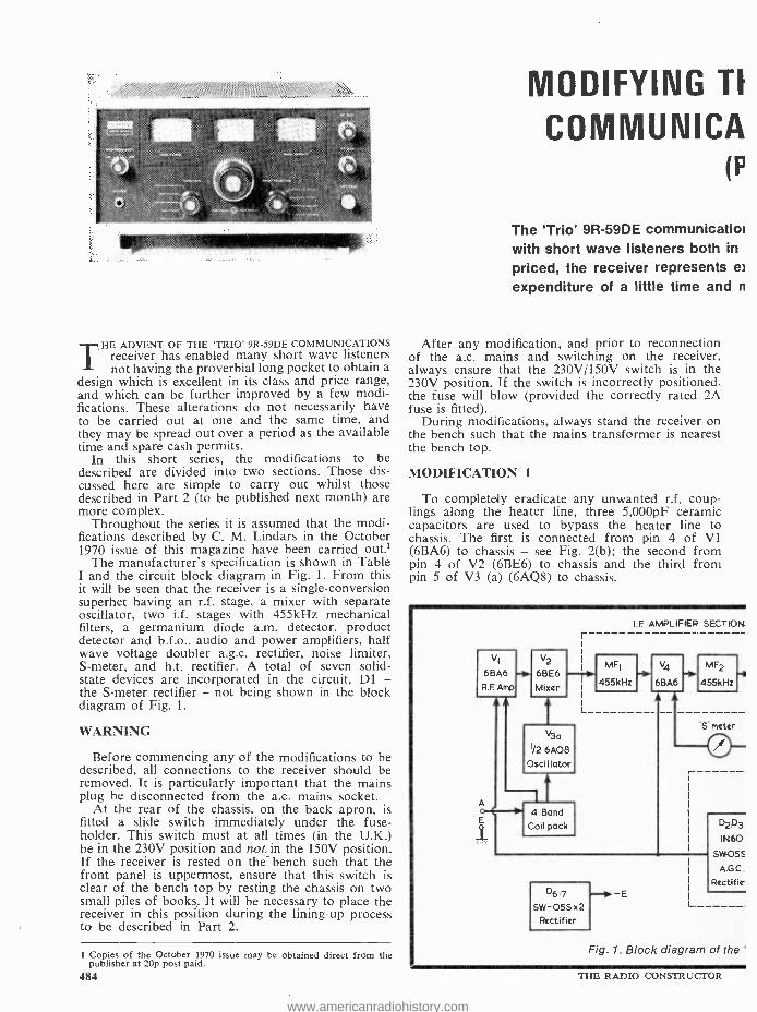
THE ADVENT OF THE 'TRIO' 9R -59DE COMMUNICATIONS receiver has enabled many short wave listeners not having the proverbial long pocket to obtain a
design which is excellent in its class and price range, and which can be further improved by a few modi- fications. These alterations do not necessarily have to be carried out at one and the same time, and they may be spread out over a period as the available time and spare cash permits.
In this short series, the modifications to be described are divided into two sections. Those dis- cussed here are simple to carry out whilst those described in Part 2 (to be published next month) are more complex.
Throughout the series it is assumed that the modi- fications described by C. M. Lindars in the October 1970 issue of this magazine have been carried out.'
The manufacturer's specification is shown in Table I and the circuit block diagram in Fig. 1. From this it will be seen that the receiver is a single- conversion superhet having an r.f. stage, a mixer with separate oscillator, two i.f. stages with 455kHz mechanical filters, a germanium diode a.m. detector, product detector and b.f.o., audio and power amplifiers, half wave voltage doubler a.g.c. rectifier, noise limiter, S- meter, and h.t. rectifier. A total of seven solid - state devices are incorporated in the circuit, D1 - the S -meter rectifier - not being shown in the block diagram of Fig. 1.
WARNING
Before commencing any of the modifications to be described, all connections to the receiver should be removed. It is particularly important that the mains plug he disconnected from the a.c. mains socket.
At the rear of the chassis, on the back apron, is fitted a slide switch immediately under the fuse - holder. This switch must at all times (in the U.K.) be in the 230V position and not, in the 150V position. If the receiver is rested on the-bench such that the front panel is uppermost, ensure that this switch is clear of the bench top by resting the chassis on two small piles of books. It will be necessary to place the receiver in this position during the lining -up process to be described in Part 2.
1 Copies of the October 1970 issue may be obtained direct from the publisher at 20p post paid.
484
MODIFYING TI
COMMUNICA (F
The `Trio' 9R -59DE communicatioi with short wave listeners both in
priced, the receiver represents e)
expenditure of a little time and n
After any modification, and prior to reconnection of the a.c. mains and switching on the receiver, always ensure that the 230V/150V switch is in the 230V position. If the switch is incorrectly positioned, the fuse will blow (provided the correctly rated 2A fuse is fitted).
During modifications, always stand the receiver on the bench such that the mains transformer is nearest the bench top.
MODIFICATION 1
To completely eradicate any unwanted r.f. coup- lings along the heater line, three 5,000pF ceramic capacitors are used to bypass the heater line to chassis. The first is connected from pin 4 of V1 (6BA6) to chassis - see Fig. 2(b); the second from pin 4 of V2 (6BE6) to chassis and the third from pin 5 of V3 (a) (6AQ8) to chassis.
VI
6BA6
RE Amp
- V2
6BE6
Mixer
I.F AMPLIFIER SECTION
V3a
I/2 6AQ8
Oscillator
--it 4 Band
Coil pack
MF1
455kHz
V4
6BA6
'S meter
D6.7 E
SW -055x2 Rectifier
L
D2D3 IN60
Sw055 A.G.C.
Rectif
1. Block diagram of the '
7HE RADIO CONSTRUCTOR
www.americanradiohistory.com
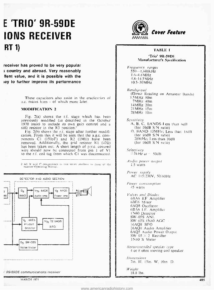
E 'TRIO' 9R -59DE
IONS RECEIVER RT 1)
receiver has proved to be very popular 3 country and abroad. Very reasonably llent value, and it is possible with the ley to further improve its performance
These capacitors also assist in the eradication of a.c. mains hum - of which more later.
MODIFICATION 2
Fig. 2(a) shows the r.f. stage which has been previously modified (as described in the October 1970 issue) to include its own gain control and a 6852 resistor in the R3 position
Fig. 2(b) shows the r.f. stage after further modifi- cation. From this it will be seen that the a.g.c. com- ponents Cl (150pF) and R2 (IMO) have been removed. Additionally, the grid resistor R1 (4752) has been taken out. A short length of p.v.c. covered wire should now be connected from pin 1 of VI to the r.f. coil tag from which Cl was disconnected.
2 All R and C designations in this series conform to those of the receiver Operating Manual.
ntCaver Feature
A6
r
I
DETECTOR AND AUDIO SECTION
D4
IN60
V7b 6AQ8 - Audio amp. t V6 6BE6
Product detector
(D5 SW -055
Noise limiter
-Po V8 6AQ5
Power amp
V7a 1/2 MOB
B.FO.
R9 -59DE communications receiver
MARCH 1971
TABI.1'. I
`Trio' 9R -59DE Manufacturer's Specification
Frequency ranges 550- 1,600kHz 1.6 -4.8 MHz 4.8 -14.5 MHz 10.5 -30MHz
Bands prend (Direct Reading on Amateur Bands) 3.5MHz 80m
7MHz 40m 14MHz 20m 21MHz 15m 28MHz 10m
Sensitivity A, B, C, BANDS -Less than 6dB
(for 10dB S/N ratio) D, BAND- 13MHz; Less than 18dB
(for 10dB S/N ratio) 28MHz; Less than 10dB (for 10dB S/N ratio)
Selectivity ±5kHz at - 50dB
Audio power output 1.5 watts
Power supply AC 115/230V, 50 /60Hz
Power consumption 45 watts
Valves and Diodes 6BA6 RF Amplifier 6BE6 Mixer 6AQ8 Oscillator 6BA6 I.F. Amplifier 1 N60 Detector SW -05S ANL SW-05S 1N60 AGC -6AQ8 BFO 16AQ8 Audio Amplifier 6AQ5 Audio Power Output SW -05 X 2 Rectifier 1N60 S Meter
Recommended speaker type 4 or 8 ohm moving -coil speaker
Dimensions lin. H, 15in. W, loin. D.
Weight 18.8 lbs.
485
www.americanradiohistory.com

The 10kí2 potentiometer in the cathode line should be replaced by a 5kû potentiometer.
In practice, it has been found that this modification causes the receiver to have enhanced sensitivity. Pro- vided the r.f. gain control is used intelligently, the circuit will not be subject to cross -modulation effects.
The foregoing modification represents the simplest that can be made to the existing r.f. stage, and it is capable of being carried out by comparative beginners. In Part 2, to be published next month, a more com- plex modification to this stage - the substitution of the higher gain type EF183 for the 6BA6 - will be described. With the high amplification then avail- able, the components which have just been removed from the grid circuit of the 6BA6 will require to be replaced; they should therefore be retained by those wishing to carry out this further modification.
most of it had been induced between the two adjacent transformers.
Unsolder all the output transformer wires, to both primary and secondary connections, then remove the transformer from the top of the chassis deck and re- locate it on the rear apron of the coil pack. When unsoldering the connections from the output trans- former, it is necessary to make notes of the wire colour codes and their correct connections. This precaution makes the re- wiring process an easy matter.
The output transformer can be secured to the coil - pack rear apron with the aid of a 6BA nut and bolt fitted with a shakeproof washer. This is fitted through an existing hole located between the r.f. coils for Bands B and C. The necessary second securing bolt is that which already holds the r.f. coil for Band A
C3
(b)
Fig. 2(a). Circuit of the ri. stage prior to modification. It is assumed that the modifications described in the October 1970 issue have been carried out
(b). Circuit of the r.f. stage after the modifications described here
MODIFICATION 3
The two basic shortcomings of the receiver are (a) excessive 50Hz a.c. mains hum - particularly noticeable when using 8Q headphones - and (b) oscillator instability above 15MHz.
The first of these will disappear once the follow- ing modification has been carried out. The second shortcoming will be dealt with next month.
The first cure for excessive hum tried out was to fit an additional smoothing circuit in the main h.t. line but this proved to be ineffective, only a small improvement being gained at the expense of a reduced supply voltage.
The a.c. mains 50Hz hum was found to be almost entirely due to the siting of the output transformer on the chassis deck right alongside the mains trans- former. Upon re- siting the output transformer under the chassis the hum virtually vanished, proving that 486
(this being the largest r.f. coil at the rear right -hand edge of the pack). Rewire the output transformer into circuit.
It will be found, after this modification, that hum has almost completely vanished, even when using headphones. The remaining very small amount of residual hum is that to be expected from most mains operated equipment.
MODIFICATION 4
This modification entails the fitting of a separate 6.3V supply for the Bandspread and Bandset dial lamps, thereby removing some of the load from the hard working mains transformer, and in addition providing a dial lamp for the S- Meter.
For this modification the following items must be obtained: a heater transformer having a rating of 6.3V at 1.5A (H. L. Smith & Co. Ltd., type LTI),
THE RADIO CONSTRUCTOR
www.americanradiohistory.com

an MES bracket (Home Radio Ltd., Cat. No. PLH2) and a round MES pilot lamp rated at 6.3V 0.3A.
The heater transformer is mounted on the chassis deck centrally between the Bandset and Bandspread tuning capacitors. The tags of the transformer should point towards the front panel. Secure the transformer to the chassis deck by means of two 4PK self- tapping screws. When drilling through the chassis deck, take great care to ensure that the drill does not cause dam- age to any of the coils, coil wiring or switch wafers.
To the input side of the transformer (clearly marked on the component) connect two lengths of p.v.c. covered wire - clear plastic- covered lighting flex is ideal - and feed the free ends down below the chassis through the Bandset dial chassis cut -out. Solder the end of one length to the tag of the on /off switch to which a yellow p.v.c. covered wire is al- ready attached, and solder the end of the remaining length to the fuseholder tag to which a brown a.c. mains input lead is connected. Ensure that the Band - set dial rotates freely and that the a.c. mains input wires to the heater transformer do not chafe against the circular drum drive.
Disconnect the existing heater leads from the mains transformer to the dial lights. These are blue and black p.v.c. leads connected to the mains trans- former tags nearest the capacitor C45 associated with the fuseholder. These lengths of wire can now be used when wiring up the S -Meter lamp.
Looking from the front panel, from the left -hand panel lamp assembly connect the blue and black leads to the heater transformer secondary (6.3V) tags. These are clearly marked on the component.
Obtain the MES bracket and secure this to the metal screening panel associated with the Bandspread capacitors. Use the existing bolt at the top of the screen nearest the front panel. Do not tighten this bolt as yet.
Screw home the new pilot lamp, carefully bend the two `legs' of the MES bracket through 45° and adjust it such that the lamp is near (but not touching) the S -Meter dial edge in a position between the S -Meter and the Bandspread dial assembly. Secure the bolt holding the MES bracket.
Connect two p.v.c. covered wires from the added dial lamp tags to the secondary 6.3V tags of the heater transformer.
NEXT MONTH In the following issue we shall be dealing with the
four steps necessary to achieve oscillator stability above 15MHz, a tape recording facility, the addition of a double -tuned i.f. stage and full frequency alignment.
NEW SPECIAL DUTY BATTERY A new 12 volt primary battery has been introduced
by Crompton Parkinson Ltd., a Hawker Siddeley Electric company, for use where good storage properties are required along with low quiescent current drains and only sporadic high current re- quirements.
The battery, type G1470, has two 4BA screwed brass terminals soldered to the inner cell assembly. The cell is protected by a plastic wrap to prevent any deterioration leading to a shortening of its life when operating in a damp environment. MARCH 1971
N EW HAND/PAN
PANEL SIGNS IDEAL FOR WORKSHOP USE
Easy to fix Permanent and durable Stapled in booklet form Designed to hang above workbench Pocket for loose cuttings Professional finish
* Set 3
* Set 4
* Set 5
* Set 6
Wording -WHITE
Wording -BLACK
DIALS -clear background
DIALS -black background
The Perfect Transfer for
the Home Constructor Each Set contains Six Sheets
25p per set (postage 22p)
MMMMMM To Data Publications Ltd.
57 Maida Vale, London, W.9
a IM NM IN
Please supply:
Set 3 Set 4 Set 5 Set 6
I enclose cheque /crossed postal order for
Name
Address
RC BLOCK LETTERS PLEASE
487
www.americanradiohistory.com

THE
'CRUSADER' SIMPLE SUPER H ET
(Part 3)
by
F. A. BALDWIN
In this concluding article, the author describes the testing and alignment of the receiver
ON COMPLETION OF THE WIRING A CAREFUL CHECK
should be made for dry joints and incorrect connections. If in doubt, always refer back to
the circuit diagram given in Fig. 1 published last month. Remove any blobs of solder which may have fallen into the chassis. Check for h.t. short- circuits by testing between the positive plate of C26 (the yellow tag of the dual electrolytic capacitor) and chassis. If an ohmmeter is used for this test, its
needle will give an `initial' kick' due to charging currents in the electrolytic capacitors.
Fit the valves and connect a loudspeaker, and an aerial and earth, to the appropriate sockets. Plug into the a.c. mains and switch on. Pilot lamp PL1 should light immediately and, after several moments, there should be a visible glow from the valve heaters. When the valves have warmed up a hiss will be evident from the speaker as R13 is turned towards maximum. Check reception over the four wavebands. The i.f. transformer cores will not be in their final aligned positions but it should still be possible to receive a number of signals on all four bands.
The accompanying Table lists test voltages ob- tained with the prototype receiver with no signal applied. These are intended as a guide only, and the usual tolerances apply.
The i.f. transformers may next be aligned. This process should not be carried out until the receiver has had at least ten minutes' warming -up time.
If a signal generator is available disconnect the aerial, select the medium wave band, apply the signal generator output between chassis and the fixed vanes
488
of Cl or C2, and set it to 465kHz. Adjust R13 to its maximum setting and attenuate the signal genera- tor until its output is just audible from the loud- speaker. If an interfering signal causes a heterodyne beat, readjust Cl, CIO until the interference clears. Then, using an insulated tool, slowly and carefully adjust the cores of IFT1 and IFT2 for maximum output from the loudspeaker, increasing signal gener- ator attenuation as required to keep the output just above audible level. None of the cores should require a great deal of adjustment, and it is preferable to align them in sequence, starting at IFT2 and working back to IFT1. The sequence should be repeated, after which the signal generator can be removed. No further i.f. alignment is then required.
Should a signal generator not be available, the i.f. transformer cores are adjusted on a received signal. The procedure is much the same, the main thing to bear in mind being that alignment should always be carried out on a weak signal. Switch to medium waves and tune in a fairly weak signal which shows no sign of fading. Attenuate the signal by using a very short aerial, such as a piece of wire several feet long laid on the bench, and carefully tune the receiver for maximum signal strength. After this, leave the receiver tuning undisturbed and adjust the i.f. trans- former cores in the same way as for the signal gener- ator. The signal input can be reduced as required by shortening the aerial or, even, by using no aerial at all. (Direct signal pick -up on the coilpack coils and wiring can occur when the receiver is not mounted in its metal case.)
Any adjustment made to the coilpack alignment should be carried out on the aerial circuits only and not in the oscillator section. The trimmers are adjust- ed at the high frequency end of each band, and the dust cores at the low frequency end. The positions of trimmers and cores are shown in Fig. 10. Each trirhmer should be adjusted with C3 set to mid - capacitance. If, however, it is found that a trimmer, even at minimum capacitance, only approaches the signal peak and cannot pass through it, reduce the capacitance inserted by C3 and leave the coilpack trimmer at minimum capacitance. It is possible that second -channel signals may be received at the high frequency end of the SW2 band, the effect being that the same signal appears at two fairly close settings of Cl, C10. Should this occur, set Cl, C10
THE RADIO CONSTRUCTOR
www.americanradiohistory.com

TABLE
Circuit Position Volts Pin 6 VI 150 Pin 8 VI 66 Pin 6 V2 88 Pin 5 V2 130 Pin 7 V3 68 Pin 7 V4 170 Pin 8 V4 180
to the setting where it has lower capacitance and trim to this. It may be necessary to `rock' C2, C11 back and forth through the signal when trimming at the high frequency end of the SW2 band, due to slight oscillator `pulling'.
After i.f. and r.f. tests have been completed, the coilpack should be switched to the `Gram' position. V3 and V4 should then amplify any a.f. signal applied to the a.f. input sockets.
When the best possible results have been obtained, the receiver may be finally installed inside its metal cabinet, whereupon it is ready for use. It is im- portant to note that the receiver must, on no account, be operated without a loudspeaker connected. If the secondary of output transformer T1 is not suitably loaded it is possible for high audio voltages to appear in its primary circuit, with consequent risk of damage.
The author's prototype performs extremely well over its entire frequency range and has provided many hours of pleasurable listening. The 'Crusader' design offers a very useful introduction to the con- struction and operation of a superhet receiver.
Transistor Power from
Valve Amplifiers by
C. P. FINN
Obtaining power for transistor circuits from
the cathode of an a.f. output valve
ANY READERS WILL KNOW THAT A POWER Msource for a transistor pre -amplifier can be 'borrowed' by tapping off voltage from the
cathode of a single -ended a.f. output valve. Usually an adjustment is made to the cathode bias resistor, and if the transistor unit is disconnected a dummy load is substituted.
An improvement is given by connecting a zener diode in the cathode circuit: this eliminates the need for a dummy load and guarantees the stability of the voltage.
Zener diode
-I i+ To transistor circuit
'-Fig: 1. -Obtaining a supply for a transistor pre- amplifier from an a.f. output valve when cathode bias voltage is greater than the
required supply voltage
I MARCH 1971\
CONNECTING THE DIODE The zener diode should be wired in place of the
cathode bias resistor. If the valve bias is greater than the required transistor supply voltage (and hence the zener voltage) then a smaller value additional bias resistor should be wired between the zener diode and the cathode, as in Fig. 1.
To find the value required for the additional re- sistor, first subtract the zener voltage from the cath- ode voltage to obtain the voltage that is to appear across it. Then divide this figure by the cathode current of the valve. Thus, if the zener voltage is
10, the cathode voltage 12 and the cathode current 50mA (= 0.05A), the value of the additional resistor is 2/0.05, or 4052. In practice a 3952 resistor would be used.
Potential divider
+
Fig. 2. An alternative circuit, which enables supply voltage to be greater than cathode bias
voltage
If the bias is less than the zener voltage the zener diode is still connected in the cathode circuit, and the grid resistor is connected, not to chassis, but to the tap in a potential divider across the zener diode. This arrangement is shown in Fig. 2. The total value of the two resistors forming the potential divider can be anywhere between 10kS2 and 100k12, and the ratio between their values should be such that the bias voltage appears across the upper. To give another example, say that zener voltage is 15 and grid bias voltage is 11. Suitable values for the upper and lower resistors in the potential divider would then be 11k1 and 4k12 respectively. The latter would, in practice, be 3.9k1ì.
439
www.americanradiohistory.com

RECENT PUBLICATIONS all SINGLE SIDEBAND FOR THE RADIO AMATEUR. Published by American Radio Relay League.
254 pages, 61 x 9 ¡in. Price £1.85 (37/ -) post paid.
The technique of SSB transmission and reception must be comprehended by all present -day and future radio amateurs. It is a complex subject, the understanding of which is greatly helped by suitable instructional literature. This book is eminently suitable for this purpose.
The Foreword to the new edition of this well -known manual states:- The pages of QST have carried the complete story of this transition from AM to SSB, covering the whole field of amateur SSB technique in the process. Building a book around the significant articles published in QST has been, and continues to be, a logical way to present the constantly changing SSB picture. This new edition continues the plan of selecting major articles describing principles, practice, and current circuit methods . . . "
"In this edition, special emphasis has been placed on those principles and methods that an amateur must observe in adjusting and using his transmitter in order to avoid causing unnecessary interference. In addition, there is a large selection of well -tried equipment designs which the experimentally inclined constructor can modify, combine and select from to his heart's content."
There is, indeed, a goodly selection of equipment designs. The chapter dealing with Exciters includes a Phasing -Type Sidebander, also a Filter -Type 100 Watt Output Sidebander. There is an excellent section on Trans- ceivers; a Solid -State SSB Transceiver, a 50 Watt PEP Output Transceiver for 75, a 7MHz Mobile SSB Transceiver, a Transistorised Transceiver (Almost), a Transceiving Converter for 160 and a 21 /28MHz Transverter for 3.5MHz. Transceivers are fully described with considerable constructional information and detail.
Linear Amplifiers and their construction are fully covered, as well as their adjustment and testing. The section on Receivers covers solid -state product detectors and gives a variety of designs for up -to -date SSB receiving equipment.
The book concludes with sections on SSB VHF Techniques, Accessories, Appendices on Valve Ratings, Regulations, etc. A most comprehensive book which can be recommended.
LOW COST PROPORTIONAL. -By W. P. Holland. Published by Radio Control Publishing Co. Ltd.
118 pages, 5; x Bin. Price £1.05 (21/-).
This excellent book is published by the proprietors of the monthly magazine Radio Modeller. In the foreword it is stated they receive many enquiries from owners of single channel radio control equipment who wish to pro- gress to a system of control giving smoother results. Upon being advised to "go multi -proportional ", these readers find that multi -proportional costs more than they can afford, with the price of a suitable transmitter and receiver being at the £100 mark.
This well -illustrated book explains how to go "multi" for much less than the figure quoted, provided one is
prepared to construct the equipment. The publication covers the subject fully, from the simplest pulsed rudder, through proportional rudder, plus sequential, selective and progressive elevator and engine control, to full dual proportional rudder and elevator, with progressive or sequential engine control. The subject matter is dealt with in a logical and concise manner. The earlier chapters cover the theory of the systems adequately and lucidly, the emphasis being on the practical applications of theory rather than theory itself.
In the constructional sections of the book, instructions are set out clearly and fully; in some cases almost as much detail is provided as can be found in a kit manual. It is of interest to note that full details are given for making up printed circuit boards - information which is taken for granted and not provided often enough in con- structional articles. There is also a description of a simple transistor tester and some hints on batteries.
A very useful book which can be recommended to radio control model enthusiasts, whether they be beginners or more experienced
490 THE RADIO CONSTRUCTOR
www.americanradiohistory.com
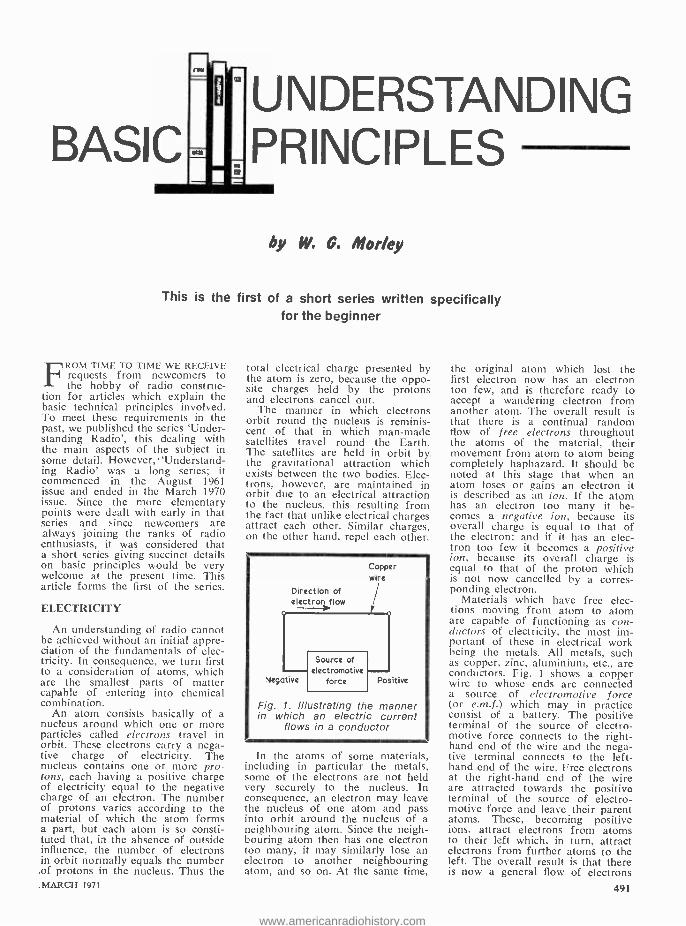
BASIC UNDERSTANDING PRINCIPLES
by W. C. Morley
This is the first of a short series written specifically for the beginner
FROM TIME TO TIME WE RECEIVE requests from newcomers to the hobby of radio construc-
tion for articles which explain the basic technical principles involved. To meet these requirements in the past, we published the series 'Under- standing Radio', this dealing with the main aspects of the subject in some detail. However, 'Understand- ing Radio' was a long series; it commenced in the August 1961 issue and ended in the March 1970 issue. Since the more elementary points were dealt with early in that series and since newcomers are always joining the ranks of radio enthusiasts, it was considered that a short series giving succinct details on basic principles would be very welcome at the present time. This article forms the first of the series.
ELECTRICITY
An understanding of radio cannot be achieved without an initial appre- ciation of the fundamentals of elec- tricity. In consequence, we turn first to a consideration of atoms, which are the smallest parts of matter capable of entering into chemical combination.
An atom consists basically of a nucleus around which one or more particles called electrons travel in orbit. These electrons carry a nega- tive charge of electricity. The nucleus contains one or more pro- tons, each having a positive charge of electricity equal to the negative charge of an electron. The number of protons varies according to the material of which the atom forms a part, but each atom is so consti- tuted that, in the absence of outside influence, the number of electrons in orbit normally equals the number of protons in the nucleus. Thus the
_MARCH 1971
total electrical charge presented by the atom is zero, because the oppo- site charges held by the protons and electrons cancel out.
The manner in which electrons orbit round the nucleus is reminis- cent of that in which man -made satellites travel round the Earth. The satellites are held in orbit by, the gravitational attraction which exists between the two bodies. Elec- trons, however, are maintained in orbit due to an electrical attraction to the nucleus, this resulting from the fact that unlike electrical charges attract each other. Similar charges, on the other hand, repel each other.
Copper wire
Direction of electron flow
Negative torce Positive
Fig. 1. Illustrating the manner in which an electric current
flows in a conductor
In the atoms of some materials, including in particular the metals, some of the electrons are not held very securely to the nucleus. In consequence, an electron may leave the nucleus of one atom and pass into orbit around the nucleus of a neighbouring atom. Since the neigh- bouring atom then has one electron too many, it may similarly lose an electron to another neighbouring atom, and so on. At the same time,
the original atom which lost the first electron now has an electron too few, and is therefore ready to accept a wandering electron from another atom. The overall result is that there is a continual random flow of free electrons throughout the atoms of the material, their movement from atom to atom being completely haphazard. It should be noted at this stage that when an atom loses or gains an electron it is described as an ion. If the atom has an electron too many it be- comes a negative ion, because its overall charge is equal to that of the electron; and if it has an elec- tron too few it becomes a positive ion, because its overall charge is equal to that of the proton which is not now cancelled by a corres- ponding electron.
Materials which have free elec- tions moving from atom to atom are capable of functioning as con- ductors of electricity, the most im- portant of these in electrical work being the metals. All metals, such as copper, zinc, aluminium, etc., are conductors. Fig. I shows a copper wire to whose ends are connected a source of electromotive force (or e.m.f.) which may in practice consist of a battery. The positive terminal of the source of electro- motive force connects to the right - hand end of the wire and the nega- tive terminal connects to the left - hand end of the wire. Free electrons at the right -hand end of the wire are attracted towards the positive terminal of the source of electro- motive force and leave their parent atoms. These, becoming positive ions, attract electrons from atoms to their left which, in turn, attract electrons from further atoms to the left. The overall result is that there is now a general flow of electrons
491
www.americanradiohistory.com
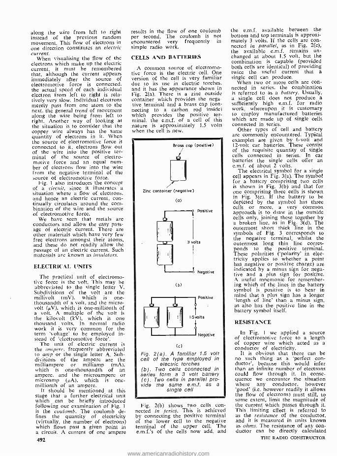
along the wire from left to right instead of the previous random movement. This flow of electrons in one direction constitutes an electric current.
When visualising the flow of the electrons which make up the electric current, it must be remembered that, although the current appears immediately after the source of electromotive force is connected, the actual speed of each individual electron from left to right is rela- tively very slow. Individual electrons merely pass from one atom to the next, the general trend of movement along the wire being from left to right. Another way of looking at the situation is to consider that the copper wire always has the same quantity of electrons in it. When the source of electromotive force is connected to it, electrons flow out of the wire into the positive ter- minal of the source of electro- motive force and an equal num- ber of electrons flow into the wire from the negative terminal of the source of electromotive force.
Fig. 1 also introduces the concept of a circuit, since it illustrates a situation where a flow of electrons. and hence an electric current, con- tinually circulates around the com- bination of the wire and the source of electromotive force.
We have seen that metals are conductors and allow the easy pass- age of electric current. There are other materials which have very few free electrons amongst their atoms, and these do not readily allow the passage of an electric current. Such materials are known as insulators.
ELECTRICAL UNITS
The practical unit of electromo- tive force is the volt. This may be abbreviated to the single letter V. Subdivisions of the volt are the millivolt (mV), which is one - thousandth of a volt, and the micro- volt (µV), which is one -millionth of a volt. A multiple of the volt is the kilovolt (kV), which is one thousand volts. In normal radio work it is very common for the term 'voltage' to be employed in- stead of 'electromotive force'.
The unit of electric current is the ampere, frequently abbreviated to amp or the single letter A. Sub- divisions of the ampere are the milliampere or milliamp (mA), which is one -thousandth of an ampere, and the microampere or microamp (pA), which is one- millionth of an ampere.
It should be mentioned at this stage that a further electrical unit which can be briefly introduced following our examination of Fig. 1
is the coulomb. The coulomb de- fines the quantity of electricity (virtually, the number of electrons) which flows past a given point in a circuit. A current of one ampere 492
results in the flow of one coulomb per second. The coulomb is not encountered very frequently in simple radio work.
CELLS AND BATTERIES
A common source of electromo- tive force is the electric cell. One version of the cell is very familiar due to its use in electric torches, and it has the appearance shown in Fig. 2(a). There is a zinc outside container which provides the nega- tive terminal and a brass cap (con- necting to a carbon rod inside) which provides the positive ter- minal. the e.m.f. of a cell of this nature is approximately 1.5 volts when the cell is new.
Brass cap (positive)
r
Zinc container (negative)
(a) --q Positive
t, 3 volts
` 5 hegaGve
lb)
(c)
Fig. 2(a). A familiar 1.5 volt cell of the type employed in
electric torches (b). Two cells connected in series form a 3 volt battery (c). Two cells in parallel pro- vide the same e.m.f. as a
single cell
Fig. 2(b) shows two cells con- nected in series. This is achieved by connecting the positive terminal of the lower cell to the negative terminal of the upper cell. The e.m.f.'s of the cells now add, and
the e.m.f. available between the bottom and top terminals is approxi- mately 3 volts. If the cells are con- nected in parallel, as in Fig. 2(c), the available e.m.f. remains un- changed at about 1.5 volt, but the combination is capable (provided both cells are identical) of providing twice the useful current that a single cell can produce.
When two or more cells are con- nected in series, the combination is referred to as a battery. Usually, a single cell does not produce a sufficiently high e.m.f. for radio work, whereupon it is customary to employ manufactured batteries which are made up of single cells connected in series.
Other types of cell and battery are commonly encountered. Typical examples are given by 6 -volt and 12 -volt car batteries. These consist of the requisite quantity of single cells connected in series. In car batteries the single cells offer an e.m.f. of about 2 volts.
The electrical symbol for a single cell appears in Fig. 3(a). The symbol for a battery comprising two cells is shown in Fig. 3(b) and that for one comprising three cells is shown in Fig. 3(c). If the battery to be depicted by the symbol has three cells or more, a very common approach is to draw in the outside cells only, joining these together by a broken line, as in Fig. 3(d). The outermost short thick line in the symbols of Fig. 3 corresponds to the negative terminal, whilst the outermost long thin line corres- ponds to the positive terminal. These polarities ('polarity' in elec- tricity applies to whether a point has negative or positive charge) are indicated by a minus sign for nega- tive and a plus sign for positive. A useful mnemonic for remember- ing which of the lines in the battery symbol is positive is to bear in mind that a plus sign has a longer 'length of line' than a minus sign, as also has the positive line in the battery symbol itself.
RESISTANCE
In Fig. 1 we applied a source of electromotive force to a length of copper wire which acted as a conductor of electricity.
It is obvious that there can be no such thing as a 'perfect con- ductor', because this would infer than an infinite number of electrons could flow through it. In conse- quence we encounter the situation where any conductor, however 'good' (i.e. however readily it allows the flow of electrons) must still, to some extent, limit the magnitude of the current which passes through it. This limiting effect is referred to as the resistance of the conductor, and it is measured in units known as ohms. The resistance of any con- ductor can be directly calculated
THE RADIO CONSTRUCTOR
www.americanradiohistory.com

T n,
(d)
Fig. 3. Circuit symbols for (a) a single cell, (b) a two -cell battery, (c) a three -cell battery, and (d) a battery having three
or more cells
from the voltage and current figures which appear in its circuit, the cal- culation being carried out with the aid of the equation:
R = E I
In this equation, R represents resistance in ohms, E represents electromotive force in volts and I represents current in amps. To take an example, let us assume that an electromotive force of 10 volts is applied across a conductor, where- upon a current of 2 amps flows in that conductor. Its resistance, from the equation, then becomes equal to 10 divided by 2. or 5 ohms.
By means of simple algebraic repositioning, the equation may be alternatively written in the forms:
Carbon composition rod
Brass end
cap
Enamel coating
Metallising
Lead -out wires
Fig. 4. A typical carbon com- position resistor, with part of the protective enamel coating removed to show the internal construction. The metallising at the end of the rod ensures good contact to the brass
end cap
MARCH 1971
I -
R and
E =IR.
These alternative versions of the equation are useful because, in practice, we often know the resist- ance of a conductor together with the voltage across it, or the current which flows through it. We can then determine the unknown 9uan- tity (current or voltage respectively) by use of the appropriate equation.
The term `ohm' is represented by the symbol 12. Multiples of the ohm are the kilohm (k12) which is equal to one thousand ohms. and the megohm (MS2) which is equal to one million ohms.
In radio work, special compon- ents are manufactured which offer fixed values of resistance. These are known as resistors and may have values as high as 20 megohms or even more. They are made in a number of different ways. Carbon composition resistors. having the general construction shown in Fig. 4, consist of a moulded rod which. before polymerisation (i.e. `setting' of its integral plastic) consisted of a mix of unpolymerised phenolic plastic (Bakelite), carbon particles, and fillers of an inert insulating material. Different resistance values are obtained in production by vary- ing the proportion between the carbon particles and the other in- gredients in the initial mix. Another version of the resistor employs a deposit of crystalline carbon or other metal deposited on the out- side of a rod of ceramic material. This type of resistor maintains its resistance value more accurately with age than does the carbon corn - position resistor, and is in conse- quence referred to as a high - stability resistor. A further type of resistor, the wirewound resistor. comprises a length of `resistance wire' (i.e. wire made from a special alloy which offers a relatively high resistance per unit length) wound on a ceramic tube, or `former' as in Fig. 5(a). The whole is then covered with a protective varnish or cement coating through which metal tags or wires. to which ex- ternal connections can be made. protrude. Some wirewound resistors have taps along part of their length, as shown in Fig. 5(b), these enabling different values of resistance to be selected. Wirewound resistors are not commonly made for values higher than about 100k12 because such values require a large number of turns of very thin resistance wire. and are difficult to manufac- ture economically.
The types of resistor we have just discussed are intended to pro- vide a fixed and unchanging resist- ance value when they are employed in a circuit. They are then described as fixed resistors when it is neces-
BUY THIS
BEST SELLER
T.V. FAULT FINDING
405/625 LINES
REVISED & ENLARGED
Edited by J. R. Davies
124 pages Only 50p
Over 100 illustrations, including 60 photographs of a television screen after the appropriate faults have been deliberately introduced.
Comprehensive Fault Finding Guide cross -referenced to methods of fault rectification described at greater length in the test.
Price 50p from your Bookseller
or post this Coupon together with remittance for 554p (to include postage) to
DATA PUBLICATIONS LTD.
57 Maida Vale, London. W.9
Please send me the 4th re- vised edition of TV Fault Find- ing, Data Book No. 5
I enclose cheque /crossed postal order
for
NAME
ADDRESS
R.C. Block Letters Please
493
www.americanradiohistory.com

Metal band
clamped over former and wire
Circular ceramic former
Resistance wire wound
on former
Togs I
(a)
iiíill*i
Protective insulating covering
Taps into resistor
(b)
Fig. 5(a). A wirewound resistor (b). Some wirewound resistors have taps to enable different values of resistance to be
selected
sary to differentiate them from an alternative type of resistor which is known as the variable resistor, or potentiometer. In the most corn - monly encountered form of the variable resistor, the material offer- ing resistance appears in the form of a circular track, along whose surface a slider or wiper can travel, as in Fig. 6(a), thereby enabling any desired resistance within the range of the component to appear between the slider tag and the two tags which connect to the ends of the track. The slider is coupled to a shaft on which is fitted a control knob. Variable resistors may have carbon composition tracks or, in the lower values, wirewound tracks. Some variable resistors are designed to be adjusted for a specific value of resistance, after which they are left alone. These are known as pre -set variable resistors or pre -set potentiometers, and normally have a screwdriver slot for adjustment of the slider instead of a shaft and control knob. An alternative con- struction for a pre -set variable resistor is illustrated in Fig. 6(b). Here, the track is provided in the form of a long flat bar along which the slider can be moved.
The terms 'variable resistor' and 'potentiometer' are often confused. To be precise, the component is a
494
variable resistor when connection is made to the slider and to one end of the track, since it then inserts a variable quantity of resistance into the circuit to which it is connected. The component is a potentiometer when a source of e.m.f. is connected across the two ends of the track, and an output, which represents a fraction of the e.m.f., is taken off between the slider and one end of the track.
The circuit symbol for a fixed resistor is shown in Fig. 7(a), and that for a variable resistor or potentiometer in Fig. 7(b), where the arrow represents the slider. An alternative symbol, employed when the component is used as a variable resistor only, is given in Fig. 7(c). The circuit symbol for a pre -set variable resistor or potentiometer appears in Fig. 7(d), with an alterna- tive version. for the pre -set variable resistor only, in Fig. 7(e). Note that the qualification 'variable' can be inferred by adding a sloping arrow, as in Fig. 7(c), and that the qualifi- cation 'pre -set' can be inferred by adding a sloping T- shaped sign, as in Fig. 7(e). These additions appear on the circuit symbols of other radio components if they are in the variable or pre -set category.
POWER
When an electric current flows in
a conductor it causes the tempera- ture of the conductor to increase. Work has in consequence been done, since electrical energy has been converted into heat. Power defines the rate of doing work and, for electricity, is measured in watts. The quantity of watts in a circuit can be calculated from the equation:
P = EI where P is power in watts, E is e.m.f. in volts and I is current in amps. Thus, if an e.m.f. of 10 volts is applied to a conductor and a current of 2 amps flows, the power dissipated in the conductor in the form of heat is 10 times 2, or 20 watts.
The term 'watt' may be abbrevi- ated to the single letter W. A thousandth of a watt is a milliwatt (mW), whilst a thousand watts con- stitute a kilowatt (kW).
Examples of electrical power dissipation in the form of heat are very common in everyday life. A familiar instance is the electric fire, which may employ, typically, one or two 1- kilowatt elements. If a I- kilowatt element is fed from 240 volts mains, the equation just given tells us that the current consump- tion in amps is 1,000 divided by 240, which is a little in excess of 4 amps. Electrical power may be converted into forms other than heat. In an electric motor, for in- stance, it is converted into rotary
Fixed contact makes continual connection to slider
Slider tag
Track
(a)
Track
Shaft
r
Threaded buse
Track end tags
(b) Fig. 6(a). Rear and side views of a variable resistor or potentiometer (b). An alternative construction, employed with some pre -set potentiometers. Connection to the slider is made by way of a
flexible wire
THE RADIO CONSTRUCTOR
www.americanradiohistory.com
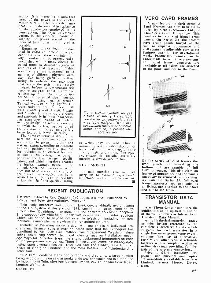
motion. It is interesting to note that some of the power in the electric motor will still be converted into heat due to the inevitable resistance of the conductors employed in its construction. The object of efficient design, in this case, will consist of keeping the power wasted in the form of heat to as low a level as possible.
Returning to the fixed resistors used in radio equipment, it is evi- dent that, since these are intention- ally manufactured to present resist- ance, they will in many circuits be called upon to dissipate significant amounts of heat. Because of this. resistors are manufactured in a number of different physical sizes, each size being given a wattage rating to indicate the maximum heat which the resistor may safely dissipate before its temperature rise becomes too great for it to continue reliable operation. As is to be ex- pected, the physical size increases as wattage rating becomes greater. Typical wattage rating figures for radio resistors are 1/10 watt, 1/8 watt, á watt, watt, 1 watt, 2 watts and 3 watts. In many radio circuits, and particularly in those incorporat- ing transistors instead of valves, wattage dissipation requirements are so small that a large proportion of the resistors employed may safely be as low as 1/10 watt in rating.
The home -constructor should note here that any one size of carbon resistor can be given more than one wattage rating according to different industry specifications. It is possible for resistors to be offered for sale to him at the rating that corres- ponds to the least stringent specifi- cation, and which therefore enables the highest wattage figure to be quoted. Since the home- constructor does not have access to the appro- priate technical specifications he is advised to employ carbon resistors at less than half the specified rating
(b)
(d)
(e)
Fig. 7. Circuit symbols for (a) a fixed resistor, (b) a variable resistor or potentiometer, (c) a variable resistor, (d) a pre- set variable resistor or potentio- meter, and (e) a pre -set vari-
able resistor
at which they are sold. Thus, a nominal watt resistor should not be called upon to dissipate more than ' -, watt, and so on. The prac- tice ensures that an adequate safety margin is always kept in hand.
NEXT MONTH
In next month's issue we shall carry on to examine capacitance. inductance and alternating current.
1111
RECENT PUBLICATION ITV 1971. Edited by Eric Croston. 240 pages, 9 x 71in. Published by Independent Television Authority. Price 75p.
This lively, attractive and colourful book covers virtually every aspect of the ITV system at the start of 1971, ranging from programme policy, through the "Dustbinmen" to questions and answers on colour reception. This exceptionally wide field is dealt with in a series of individual sections which will appeal to anyone interested in television, including the non- technical layman who merely views the transmitted pictures.
Included in the many subjects dealt with are details of individual pro- grammes, finance (and it may be noted here that the Exchequer has benefitted by well over £300 million from Independent Television since 1954), advertising control, technical notes on receiver installation, cover- age maps for individual transmitters, and background information on each of the programme companies. There is also a very extensive bibliography listing such diverse titles as "Television And The Child ", "One Hundred Years of Georgian London" and the Data Publications' "Understanding Television ".
"ITV 1971" contains many photographs and diagrams, a large number being in colour. It is on sale at bookstands and bookstalls and is distributed by Independent Television Publications Limited, 247 Tottenham Court Road, London, W1P OAU.
MARCH 1971
VERO CARD FRAMES A new feature on their Series 3
Card Frames has now been intro- duced by Vero Electronics Ltd., of Chandler's Ford, Hampshire. This involves two styles of hinged front panels. On Series 3A the frames have front panels hinged at the side to improve appearance and still retain the adjustable card width features essential for development work. Production frames can be tailor -made to exact requirements. Full card frame apertures are available as all fixings are attached to the panel and not to the frame.
.0
On the Series 3( card frames the front panels are hinged at the bottom and are capable of full 180" movement. This also gives an improved appearance and the panels can easily be removed for servicing. As with the Series 3A full card frame apertures are available as all fixings are attached to the panel and not to the frame.
TRANSISTOR DATA MANUAL
Aso (Thorn Croup) announce the publication of an up -to -date edition of the well -known Ay() International Transistor Data Manual.
An alphabetical /numerical index provides instant reference to the complete characteristic data which is given for each transistor in a single line entry across some twenty columns. The lists of alternatives for CV and other types is retained, together with a complete section of outline drawings providing full de- tails of the relevant connections.
Price is £4.40 (including UK postage and packing) and copies are immediately available from Avo Limited, Avocet House, Dover, Kent.
495
www.americanradiohistory.com

AMATEUR RADIO
SCIENTIFIC STUDIES VERY INTERESTING PAPER BY GEOFF STONE. U31 lL ..
Aappears in the current issue of Region I News, the journal of the International Amateur
Radio Union, Region I Division, which gives a very good idea of the amount of genuine scientific work which has been accomplished in recent years by radio amateurs working through the Radio Society of Great Britain Scientific Studies activities.
The present phase of RSGB Scientific Activity stems from the International Geophysical Year of 1957, since when scientific programmes started for IGY have been continued. G3FZL reminds his readers that these programmes owe much to Dr. R. L. Smith -Rose who is a Past President of the RSGB and who has spent much of his life as a pro- fessional radio engineer, latterly as Director of the Radio and Space Research Station.
During the IGY, emphasis was on radio propaga- tion phenomena associated with sunspot maximum, such as radio wave reflection and scattering from the aurora borealis. New information on VHF propaga- tion by this mode was obtained, which has progressed to closely related fields such as ionospheric sporadic E propagation in the 50 to 70MHz region.
Another subject investigated was that of tropos- pheric propagation, the original object being to find means of predicting unusual propagation conditions, suitable for use by the average radio amateur equipped only with the more usual, readily available. meteorological instruments. The fact that this project showed an unsuccessful correlation, does not detract from its value, as useful conclusions could be drawn from the results obtained. For instance, it was apparent that a barometer, coupled with a know- ledge of the mechanics of tropospheric wave propa- gation, and a study of current weather maps, would enable quite good predictions to be made.
The Society's interest in tropospheric propagation resulted in it being asked by the CCIR to partici- pate in obtaining data on VHF -UHF propagation across land -sea paths of domestic TV frequencies, in an effort to help the prevention of mutual inter-
Terence between TV stations. "Co this end, the Soci- ety set up a 432MHz beacon, GE3GEC, in London and invited PE1PL in the Hague to set up an auto- matic receiving station. As a result, data was ob- tained which helped in the revision of the CCIR VHF propagation curves used by broadcast engi- ners for planning purposes. As Geoff Stone com- ments:- "This is an excellent example of international cooperation and of the work of radio amateurs harnessed to professional requirements."
An interesting observation from the IGY was that amateur radio reports derived much of their value from the fact that there were many of them from widely dispersed locations. Moreover their value was greatly enchanced if they were quantitive rather than qualitative and disciplined rather than haphazard. This factor encouraged the Society to increase its beacon programme, a beacon having the virtue of giving a continuous signal source of known strength and thus encouraging a small group of observers to report regularly.
Geoff Stone concludes his most informative and interesting paper by outlining the Society's current scientific programme. Work on auroral and E layer propagation continues, particularly in relation to 70MHz, with the establishment of beacons in Gibral- tar, Rhodesia and Iceland. More intensive investiga- tions into microwave propagation are being planned, with the setting up of 1296MHz beacons in London and on the East Coast of England. The Society is also cooperating in the World Amateur Beacon Project on 28MHz. As the author states:- "Com- pletely new fields remain to be explained and much consolidation in known fields remain to be done. Amateur space communication opens a vast new field which will prove of great interest in the next decade. It can confidently be said that the radio amateur still has much to contribute in scientific projects and it is the responsibility of national soci- eties to stimulate and co- ordinate such activities ".
A.C.G.
CASSETTE TAPE HEAD CLEANING The Bib Division of Multicore Solders Limited,
Hemel Hempstead, Hertfordshire, announce the in- troduction of their new Cassette Tape Head Clean- ing Tape, suitable for all compact cassette type re- corders and car player units.
The unit comprises a cassette tape container in which high quality cleaning tape has been incor- porated to clean tape heads, capstan and pinch wheel. It is very simple to use, in the same manner as a tape cassette it is placed in the machine and operated in the playback position.
A plastic container is provided for the cleaning tape cassette. This handy new accessory retails at lOs 7d. / 53p including p.t.
496 THE RADIO CONSTRUCTOR
www.americanradiohistory.com

LOS -COST TV AEKIAL
by
T. WHITE
This simple indoor television aerial can be made up in half an hour. In many cases, it will give a better performance than is pro- vided by manufactured indoor aerials of the
`rabbit's ears' variety
ANY READERS MAY RECALL THAT FAMOUS TV
M ANY
in which the late Tony Hancock spent some five minutes or so vainly trying to find
the best position for his `rabbit's ears' indoor TV aerial. Those who have similarly tried to position aerials of this type will probably have encountered the same sort of situation. The average living -room, with its metal fittings, wiring and adjacent plumbing, is virtually saturated with reflected TV signals, these having an almost infinite variety of amplitude and phase differences. Moving an indoor aerial through a foot or so can sometimes make all the difference between a perfectly acceptable picture and one that will not even lock.
REMOVING GUESSWORK
The aerial to be described here does not overcome the positioning problem, but it takes much of the guesswork out of the process. Also, since the con- ductors used are much thicker than the telescopic rods of many 'rabbit's ears' aerials, signal pick -up is significantly greater. A further advantage is that the feeder to the receiver is well matched at the aerial end, whereupon standing waves on the feeder itself are much less evident. With 'rabbit's ears' aerials it sometimes happens that the positioning of the feeder is nearly as important as the positioning of the aerial itself.
Before carrying on to details of the assembly of the aerial it must be emphasised that, considering the unpredictable nature of the TV field strength pattern inside a house, success in all cases cannot be guaranteed. Also, the performance cannot, of course, be equal to that given by a proper outdoor aerial mounted up in the air above the roof. How- ever, the writer has used aerials of the type to be described on several occasions, with results superior to those given by 'rabbits ears' aerials. In one instance where the aerial was used, the local Band I
signal could be received at good strength and good quality where previously it could not be resolved at all. It should be pointed out that, in any event, the cost of the aerial is very small, since it consists merely of lengths of coaxial cable, plus insulating tape and string! MARCH 1971
The aerial is intended for use on Bands I and III only. U.H.F. signals can only be reliably picked up with the correct aerial made for the job and, pre- ferably, mounted outside.
ASSEMBLY
The assembly of the indoor aerial is illustrated by the accompanying diagram. It consists of a feeder of ordinary 7552 coaxial cable which couples to two vertical pieces of similar cable positioned as shown. These two pieces of cable form the upper and lower elements of a conventional half -wave dipole.
In making up the aerial, first select a suitable length of 75f2 coaxial cable for the feeder. About four yards should be adequate for the average in- stallation. Fit a coaxial plug at one end; this will eventually be plugged into the aerial input socket of the receiver. Cut back the outside insulation at the other end by about láin., then tease out the strands of the outer braiding so that they can be twisted up into a pigtail which leaves the cable just after the end of the outer insulation. Strip back the insulation from the inner conductor of the cable for about +in.
a
Upper element
Feeder to receiver
Coaxial plug
Twine
Lower element
Tape
Illustrating the method of assembly of the aerial. In practice, the connection between the centre conductor of the feeder and the upper element is taped up before the twine is fitted
Cut two further lengths of 7552 coaxial cable to the dimension 'X' (which will be discussed shortly). Strip back the outer insulation of one length by about tin. Without teasing out the strands, push back the outer braiding, leaving the inner conduc- tor and its insulation protruding. Cut the inner con- ductor and its insulation at a point +in. from the end of the outer insulation. Pull the braiding back out again, twisting its strands up into a pigtail. Note that no connection is made to the inner conductor of this cable; connection is made to the outer braiding only. Repeat the process with the second length of coaxial cable which was cut to length 'X'.
497
www.americanradiohistory.com

Solder the centre conductor of the feeder section to the pigtail of braiding from one of the two equal- length pieces of cable. This piece of cable now becomes the upper element of the dipole aerial. Solder the pigtail of braiding from the feeder section to the pigtail of braiding from the second equal - length piece of cable. This second piece of cable is now the lower element of the dipole. Using ordinary electrician's black insulating tape, completely cover the centre conductor from the feeder section and the pigtail of braiding from the upper element so that all metal is covered. Wrap a short length of the tape round the lower element of the dipole near the bottom to act as a marker. This is done because it is difficult to differentiate between the upper and lower elements after assembly has been completed.
Take a short length of thin twine and secure it to both the upper and lower elements in the manner shown in the diagram. The twine is passed around the lengths of cable about 1 to 1+in. away from the termination of the outer insulation. The purpose of the twine is to take the strain from the solder joints when the aerial is suspended by its upper end. Ex- Boy Scouts and Master Mariners will be able to make a neat job of whipping the twine to the cable, but a high degree of skill and neatness is not really required here. The tension on the twine will be low only.
Finally cover all the exposed conductor and the twine with insulating tape to form a neat T- junction. The indoor aerial is then complete.
ELEMENT LENGTH
The length, `X', of the two dipole elements depends upon the channel to be received. Calculated values for the channels in Bands I and III are given in the Table. In all the cases encountered by the writer, it has been found adequate to cut the elements for reception of the local Band I channel. Reception on the local Band III channel has then been good. This
may, of course, have been a matter of luck, and in some localities it may be found better to cut the elements for reception of the local Band III signal, after which it may be found that the resultant aerial copes adequately at Band I. It may even be neces- sary to use separate Band I and Band III aerials. As was stated at the beginning of this article, success cannot be completely guaranteed in a situation as unpredictable as that of indoor aerial TV reception. In the worse cases some experiment is inevitable.
TABLE Values of dimension `X' for television channels in
Bands I and III. Channel Channel `X'
1 5ft. 3in. 8 1 ft. lin. 2 4ft. lin. 9 lft. 22in. 3 4f t. 4in. 10 1 ft. 2in. 4 3ft. loin. 11 lft. 1iin. 5 3ft. lin. 12 1 ft. lin. 6 lft. 4in. 13 1 ft. Olin. 7 lft. 31in.
After the aerial has been completed, try to find the best position for it in the room. Ideally, both upper and lower sections should be vertical but, if this cannot be achieved, it is in order to have part of the lower section horizontal. If the constructor is fortun- ate, he may be able to conceal much of the aerial behind furniture. Also, the aerial can be made up using white, instead of brown, coaxial cable, if this matches in better with room decoration.
As a final point it is, in general, better to have the dipole elements some distance away from the TV receiver. This reduces interaction with the receiver r.f. and i.f. circuits and obviates the picture `noise' that some otherwise serviceable line output stages tend to radiate.
ELECTRONIC COMPONENTS
BOARD CONFERENCE
A wide- ranging conference on electronic compo- nents, to be held at the Royal Garden Hotel, Ken- sington, London from May 18th to 21st, will invite component manufacturers and users to argue on a no- holds- barred basis. One debate, for instance, covers the theme `The components industry - dead or alive ?'
The conference has been organised by the Elec- tronic Components Board and will be held in con- junction with the International London Electronic Component Show at Olympia, London.
Title of the conference is `Forward into the 70's.' It will be opened by Dr. I. Maddock, Controller, Industrial Technology at the Department of Trade and Industry.
The discussions will be far from the normal style at technical meetings. As well as the `Dead or alive ?' debate, which will be on the lines of the `Your Witness' TV feature, there will be a brains trust for a 498
frank discussion of customers requirements and problems.
The conference covers a lot of ground. One morn- ing is devoted to dealing with the B.S.9000 scheme, the series of British Standards effecting assessed quality components. The scheme is now in course of intro- duction and is of vital interest to manufacturers and users, and will have international impact.
Government and British Standards Institution ex- perts will explain the implications and scope of the scheme while manufacturers and users will comment on operating experience and customer reactions.
During part of the conference, discussions will be divided so that those interested either in passive or active components can both be fully served. Through- out there will be late afternoon sessions organised by specialist groups of the Electronic Components Board.
A number of technical `state of the art' papers will include probes into the future developments likely in the industry.
General interest in the conference is underlined by the fact that the 55 papers required were 'over- subscribed' by more than 250 per cent.
THE RADIO CONSTRUCTOR
www.americanradiohistory.com
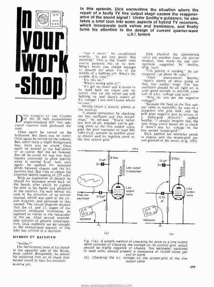
n n
work shop
D ICK LOOKED AT THE CHASSIS of the 20 inch monochrome single- standard 625 line tele-
vision receiver with profound dis- trust.
Once again he turned up the brilliance. But there was no raster. Once again he turned up the volume. But, apart from a slight background hiss, there was no sound. Once again he looked at the half -dozen or so valves that the set boasted. But all he could see was that their heaters continued to glow merrily away at normal level. And, once again, he applied his testmeter prods between chassis and the h.t. positive line. But only to obtain the expected supply reading of 225 volts.
With an expression of despair he placed his testmeter prods back on the bench, after which he cupped his chin in his hands and glowered at the receiver. He next turned his eyes in the direction of its service manual, which was open at the cir- cuit diagram, and glowered at this instead. The circuit diagram showed that the r.f. and i.f. stages of the receiver employed transistors, as opposed to valves in the remainder of the set. After several unprofit- able minutes of gloomy preoccupa- tion, Dick suddenly sat up straight in the unequivocal manner of one who has arrived at a decision.
HYBRID TV RECEIVER
"Smithy!" The Serviceman, busy at his bench
at the opposite side of the Work- shop, sighed. Resignedly, he placed his soldering iron on its stand then turned round to face his assistant. MARCH 1971
In this episode, Dick encounters the situation where the repair of a faulty TV line output stage causes the reappear- ance of the sound signal ! Under Smithy's guidance, he also takes a brief look into some aspects of hybrid TV receivers, which incorporate both valves and transistors, and finally turns his attention to the design of current quarter -wave
u.h.f. tuners
"Am I never," he complained wearily, "to get any peace this morning? This is the fourth time you've pestered me up to now. What's more, you always manage to disturb me when I'm in the middle of a fiddling job. What's the trouble this time ?"
"It's this set." "What's wrong with it ?" "It's got no raster and it seems to
be dead both on vision and on sound. And yet the valves are still lighting up and there's stacks of h.t. voltage. I just don't know where to start."
Smithy threw a cursory glance at the receiver
"I should commence by checking the line oscillator and line output stage," he advised. "You'd better see, first of all, whether you're get- ting drive to the line output valve grid. Set your testmeter to read 200 volts f.s.d., connect its positive prod to chassis and its negative prod to the line output grid."
HTi-
2 2 kn O INF
From line oscillator
OOINF
Testmeter
(a)
Dick checked the appropriate valve pin number from the service manual, then made the test con- nections suggested by Smithy. (Fig. 1(a)).
"I'm getting a reading," he an- nounced, "of about 90 volts."
"Then," pronounced Smithy, "there's plenty of drive going to that line output stage. The line oscillator should be all right or, at least good enough to provide some sort of e.h.t. voltage and scan."
"Why do you get the negative voltage ?"
"Because the feed to the line out- put valve is, basically, by way of a capacitor and grid leak, and the grid goes negative just as occurs in a leaky -grid detector," replied Smithy. I should imagine that the next thing you'd better do is check if there's any h.t. voltage on the line output screen -grid."
Dick applied his testmeter prods to chassis and the screen -grid pin and glanced at his meter. (Fig. 1(b)).
Line output transformer
Line output valve
O INF
Testmeter
(b)
Line output valve
Fig. 1(a). A simple method of checking for drive to a line output valve consists of checking the voltage on its control grid, which should be highly negative of chassis. The testmeter, switched to read volts, should present a resistance of 10,000 ohms per
volt or more (b). Checking the h.t. voltage on the screen -grid of the line
output valve
499
www.americanradiohistory.com

Your Local Supplier LONDON
Established 1910
H. L. SMITH & CO. LTD.
Comprehensive stocks of
components by
all leading makers.
287 -9 EDGWARE ROAD LONDON W.2
Tel: 01 -723 5891
THE
MODERN BOOK CO.
Largest selection of English &
American radio and technical books in the country.
19 -21 PRAED STREET, LONDON, W.2
Tel: PADdington 4185/2926
ST. HELEN'S RADIO Hi -Fi Equipment Tape Recorders Radio Receivers
Television
& ELECTRONIC TEXTBOOKS SPECIALISTS IN RADIO
ST. HELEN'S GARDENS LONDON W.I0 Tel: 01 -969 3657
BEDFORDSHIRE
When in LUTON, BEDS, you must visit the . . .
SELF -SERVICE RADIO COMPONENTS SHOP
Serve yourself from a selec- tion of 1,200 boxes of Manu- facturers' surplus stocks and
save money. 9 a.m. to 5.30 p.m. every day.
Closed all day Wednesday.
SURPLECTRONICS 216 LEAGRAVE ROAD
LUTON, BEDS
500
"Hello," he remarked. "We seem to have struck gold first go! There's no voltage on this screen -grid."
"No voltage at all ?" "Nary a sausage." Despite his irritation at having
been interrupted, Smithy looked pleased at the outcome of his suggestion. Forgetting his own work for the moment he wandered over, looked at the chassis on Dick's bench and then at his assistant's testmeter. Dick had been right: there was no voltage whatsoever on the screen -grid of the line output valve.
Smithy reached over and switched off the receiver.
"Check the resistance," he said, "between that screen -grid and chassis."
Dick busied himself with the setting up of his testmeter, then once more touched its prods to the screen -grid pin and chassis.
"There is," he remarked, "a dead short here."
"That will be your fault then," stated Smithy. "The short could be in the line output valve so you'd better remove it from its socket to make certain, but it will much more likely be in the 0.1µF bypass capa- citor which ties that screen -grid down to deck."
As Smithy watched, Dick quickly checked the valve, which proved to be blameless so far as internal short- circuits were concerned. He next examined the printed circuit around the line output valve to make cer- tain that no accidental bridging had occurred between the foil connecting to the screen -grid pin and that connecting to chassis. Finally, he cut one lead of the suspect screen -grid bypass capacitor. He next applied his testmeter, still switched to read resistance, across this component. (Fig. 2).
"That's it," he called triumphant- ly. "This capacitor's short- circuit."
Lead -out cut..
Testmeter (switched to ohms)
`we
Printed board
I
Fig. 2. In some instances the only decisive way of finally ascertaining that a capacitor is short- circuited consists of cut- ting one lead -out to isolate it from the circuit in which it con- nects. The lead should be cut such that the capacitor may be resoldered into circuit if it is
found to be serviceable
"Very good," commented Smithy. I'll just hang on here whilst you
replace it, to see what happens afterwards. I'm beginning to get interested in this set."
As Dick walked over to the spares cupboard to get a replace- ment capacitor, Smithy brought his stool over and settled himself corn- fortably. Dick returned and picked up his side -cutters.
"There are, of course," remarked Smithy chattily, as Dick worked on the repair, "quite a few other ways in which we could have determined that the line output stage wasn't working properly. For instance, al- though 625 line output transformers are a lot quieter, partly because they run at a higher frequency than the old 405 line output trannies used to be. you can still often hear them singing away when the line output stage is working properly. In our case we were fortunate in being able to find the fault as easily as we did."
"The new capacitor's in now," interrupted Dick. "Shall I switch the set on ?"
"By all means." Dick turned on the receiver. After
a short while the booster diode cathode rose to emitting tempera- ture, allowing h.t. current to flow to the line output valve anode. At once, a modulated raster showing the morning test pattern became visible on the screen. Much to Dick's surprise, the accompanying test music also appeared, this being reproduced by the loudspeaker with good volume and excellent clarity.
TRANSISTOR SUPPLY
"Hell's teeth," exclaimed Dick, "this set must be haunted! I've just fixed a line output stage fault and, lo and behold, the sound circuits come into operation as well!"
"There's an easy explanation for that," said Smithy. "And seeing that you've got the service manual for the set open on your bench I'm surprised you haven't spotted it yourself. Just look at this bit."
Smithy pointed to the circuitry around one of the windings on the line output transformer. (Fig. 3). Dick looked at the manual a little uncertainly.
"That winding," he ventured doubtfully, "goes to the line deflec- tor coils, doesn't it ?"
"Of course it does," returned Smithy irritably. "but if you look again, you'll see there's a tap in it which connects to a rectifier and then to a reservoir and smoothing circuit. The rectifier circuit provides about 18 volts positive of chassis, and supplies all the transistor cir- cuits of the receiver."
"Blimey," said Dick, taken aback at this unexpected evidence of the
THE RADIO CONSTRUCTOR
www.americanradiohistory.com

fiendish cunning of TV receiver designers," so it does. Do you know, Smithy, I've fixed quite a few sets of this type before, and I've never even noticed that the transistors get their supply from the line output stage."
"It's a fairly common practice," said Smithy. "There are plenty of advantages to the scheme, the first of these being its simplicity and low cost. It's only necessary to add a winding to the line output trans- former of the receiver, or to tap into a winding that's already there, whereupon a low voltage supply for the transistor stages becomes available with nothing other than a simple rectifier circuit. Secondly. the line output stage will very probably incorporate stabilised width control to take up variations in mains voltage, with the result that the transistor supply will be reason- ably well stabilised as well. A third feature is that the transistor stages don't come on until after the line output stage is running. This avoids one of the design problems that occur with gated a.g.c. circuits. If the r.f. and i.f. stages become opera- tive before the booster diode warms up after switching the set on from cold, you can, unless suitable pre- cautions against the effect are pro- vided, have the situation where there is no a.g.c. voltage because of the absence of gating pulses from the line output transformer. With the present system this particular problem doesn't even arise."
"I see," said Dick, examining the circuit of the receiver more closely. "Incidentally, I notice that in this set the stages using transistors are those in the vision and sound i.f. strip, the a.g.c. circuit and the tuner unit."
"That's right," confirmed Smithy. "And since this is a single -standard 625 line receiver, it only has a
Aerial tuned circuit Channel response centre
Aerial Aerial
tuned 11.- input circuit
Bondposs response
R.F.
amplifier
1,8OOpF
Supply to transistor stages IOn
18V
160 160
IOn
1' 1
YF
I IpF III
11
To line deflection
coils
Winding on line output transformer
Fig. 3. A typical transistor supply circuit, as employed in hybrid television receivers. The BA148 is a silicon rectifier, and has a p.i.v. of 350 volts and an average maximum forward
current of 0.3 amp
u.h.f. tuner. There's no tuner unit for Bands 1 and III at all. I must say. incidentally, that I fully ap- proved of these transistor u.h.f. tuners when they first appeared. The old valve u.h.f. tuners didn't give too much trouble, I know, but my experience has been that the present run of transistorised tuners knocks spots off them so far as freedom from electrical faults is concerned. I assume you've noticed, by the way, that the tuner in this set uses quarter -wave resonant lines."
Dick looked uncertainly at the tuner unit circuit diagram in the service manual. -
"Does it ?" he queried blankly. "As opposed," continued Smithy,
warming to his theme, "to half - wave resonant lines."
"Ah yes, now," said Dick. "The old half -wave resonant lines, there."
"It's always obvious from the
Vision carrier
Channel centre
ü
-}- Bandpass
tuned
circuits
Mixer-
oscillator
i
Sound carrier
Combined overall response fed to mixer
r--
Oscillator tuned circuit
I.F.
tuned
circuit
To I.F.
amplifier
Fig. 4. General television tuner design employs the stage layout shown here. The responses are idealised and are applicable in particular to v.h.f. tuners. U.H.F. tuners may not exhibit so marked
a bandpass response MARCH 1971
Your Local Supplier HAMPSHIRE
BOURNEMOUTH LARGEST HI -FI AND RADIO COMPONENT STORE IN THE SOUTH
FORRESTERS NATIONAL RADIO SUPPLIES LTD. 70-72 Holdenhurst Road
Bournemouth Telephone 25232
SUSSEX
E. JEFFRIES For your new television set .
tape recorder, transistor radio, and hi -fi equipment.
PHILIPS, ULTRA, INVICTA, DANSETTE, MASTERADIO, PERDIO.
MARCONI, PHILCO. FIDELITY
6A Albert Parade, Victoria Drive.
EASTBOURNE SUSSEX
YORKSHIRE
WILSIC ELECTRONICS LTD. Your local supplier for
EAGLE PRODUCTS CYBERNAT MOTORING AIDS
WILSIC HI -FI, MUSICAL EQUIPMENT, KITS AND
COMPONENTS Send 1Sp (3/ -) for our Catalogue
(Eagle Products Catalogue 20p (4/ -)
6 COPLEY ROAD DONCASTER
EIRE
PEATS for PARTS ELECTRONIC COMPONENTS
RADIO & TELEVISION For the convenience of IRISH
enthusiasts we supply. The Radio Constructor Data Books and Panel -Signs Transfers Also a postal service
Wm. B. PEAT & Co. Ltd 28 PARNELL STREET
DUBLIN 1
50I
www.americanradiohistory.com

circuit diagram when a u.h.f. tuner has quarter -wave lines."
"Now you put it that way," said Dick, "the obviousness is remark- able even."
"Quarter -wave lines have one end connected to chassis."
"True," said Dick, "very true." "Whereas half -wave lines are
floating and have tuning capacitance to chassis at both ends."
"At both ends," repeated Dick. Smithy turned a wary eye on his
assistant. "Have you," he asked suspicious-
ly, "any idea of what I'm talking about ?"
"I haven't," grinned Dick, "the faintest clue. I got lost immediately after the freedom from electrical faults bit !"
U.H.F. TUNERS
Smithy chuckled. "Oh well," he said, "I suppose I
can't blame you. It's a very long time since we last had a session on u.h.f. tuners and, seeing that we've got an actual tuner to look at as well as the circuit diagram in front of us, it won't do any harm to have a short discussion on them now. I'll have to sketch out a few diagrams, so perhaps you can lend me your note -pad."
"Certainly," said Dick magnani-
LI
Aerial input J
502
mously, as he reached over for the pad.
He picked this up, shaking off a random surface coating of odd nuts, bolts and small items of hard- ware, tapped its side smartly on the bench surface to dislodge the dust it had collected, then passed it over to Smithy. That worthy looked distastefully at the yellowing top sheet.
`When," he asked, "was the last time you used this pad ?"
"I can't remember," replied Dick airily. "In any case I don't bother to make notes these days. I keep things in my head instead."
"Well," retorted Smithy wither- ingly, "considering its great size and its vast emptiness there should be plenty of space for them."
Holding the paper disdainfully between thumb and finger tips, the Serviceman tore off the top sheet and consigned it to Dick's rubbish bin. The sheet underneath, yellowed at the edges only, appeared to be just worthy of Smithy's approval. He took out his pen and proceeded to scribble out his first sketch. (Fig. 4).
"U.H.F. tuners," he resumed, "have pretty well the same basic stage line -up as have almost all TV tuners, ever since the first v.h.f. turret types came into use. There is a tuned aerial input stage offering a
4 -gang tuning capacitor
Coupling line
Coupling line.
- -I 390n
L2
T I
I
Slot in screen
Ikn VON
L3
Coupling lines
/ pF
BF 181
L4
single peak at the centre of the channel being received, this being followed by an r.f. amplifier which feeds into a bandpass pair of tuned circuits. Ideally, the bandpass pair provides a double- humped curve which is also centred on the channel being received. The output of the bandpass pair is fed to the mixer or frequency- changer and the overall response, from aerial to mixer, is a combination of the aerial input tuned circuit peak and the double - humped response of the bandpass pair. This combination should be a relatively flat response with sound and vision carriers sitting on the edges of the flat part. In practice, it may be a little difficult to get a response as good as the one I've just drawn on all channels with a multi -channel tuner, but small dis- crepancies in amplitude between sound and vision carriers up to some 3dB overall are permissable and won't cause much trouble."
The Serviceman paused for a moment.
"Getting back to the tuner stages themselves," he went on, "we now have a signal which has passed through the aerial tuned circuit, r.f. amplifier and bandpass tuned cir- cuits, and which is then applied to the mixer. In u.h.f. tuners the mixer also acts as oscillator, the oscillator frequency being above signal fre-
27 kn
L__
I.F.
Il.Loutput III Coil
Supply +
270n
5 kn
IIV- I 1 F 200pF IP00
pF Test point
680n
1,000 pF
C
L1- L4 resonant lines
Fig. 5. Typical quarter -wave u.h.f. tuner circuit, shown in slightly simplified form. The component values are representative of
current practice
II To I.F
amplifier input tuned circuits
A.G.C.
THE RADIO CONSTRUCTOR
www.americanradiohistory.com

quency. The output of the u.h.f. mixer consists of i.f. vision carrier at 39.5 MHz and i.f. sound carrier at 33.5 MHz, and this band of frequencies is passed through an i.f. tuned coil in the tuner and then fed to the i.f. amplifier. Okay ?"
"Yes," said Dick contentedly. "This is all standard TV tuner stuff."
"Good," returned Smithy. "Well now, that's the stage line -up for most u.h.f. tuners. There are excep- tions, though, in so far that some u.h.f. tuners omit the aerial input tuned circuit and relay on the band - pass pair only for r.f. selectivity. The aerial input to the r.f. amplifier in these tuners is aperiodic. How- ever, you can forget about the aperiodic types for the time being and concentrate on tuners like the one in the receiver we have here. This is one of the types that does have an aerial tuned circuit."
Smithy indicated the circuit dia- gram of the tuner unit. (Fig. 5).
TUNED LINES
"The next thing you have to remember," he continued, "is that u.h.f. frequencies require tuned circuits in which the inductive part is much too small in value to be provided by the usual type of wound coil. Because of this the tuned cir- cuits employ 'lecher lines', which are usually referred to just as 'lines'. To understand how these lines work, it's necessary to take an ini- tial gander at elementary aerial theory."
Smithy drew a further sketch on Dick's note -pad. (Fig. 6(a)).
"Here," he said, "is an electrical conductor. If this were employed as a half -wave dipole aerial at the requisite frequency, what would be the voltage and current distribution along its length ?"
Smithy handed Dick his pen. After a little thought, Dick added two lines. (Fig. 6(b)).
"Would it be like this ?" "You've got it right," confirmed
Smithy, pleased. "An important point is that the voltage is of oppo- site polarity and is at maximum amplitude at the ends, so that the conductor, at the frequency at which it is a half wavelength long, acts in the same way as a parallel tuned circuit. In half -wave u.h.f. tuners the lecher lines consist of strips of metal somewhat less than half a wavelength long. This short- ening reduces the inductance pre- sented by the lines so that, on their own and acting as a dipole, they would resonate at too high a fre- quency. They are then brought down to the desired frequency by adding capacitance to earth at both ends, whereupon the lines plus the capacitance provide the tuned cir- cuits for the tuner. (Fig. 7(a)). The 'earth' in this case is the actual MARCH 1971
1/2 wavelength
(a)
(b)
Fig. 6(a). A conductor whose length is equal to a half wave- length at a specific frequency (b). The voltage and current distribution in the conductor if this is energised as a dipole
aerial
tuner chassis which can be assumed to possess very low inductance in itself. As you may imagine, if the capacitances at each end of a half - wave line are equal, then the centre of the line has zero r.f. voltage with respect to earth."
"What about the quarter -wave tuners ?"
"The quarter -wave tuners were a logical development from the half - wave types," replied Smithy. "It was realised that, since there could be zero r.f. voltage at the centre of a resonant half -wave line relative to earth, that centre could be con- nected directly to earth without up- setting the operation of the line and the associated circuit. The further reasoning was that, since the centre of the line could be connected directly to earth, there was no point in continuing the line after that earth connection!"
"Hey ?" "It's quite true," said Smithy.
"And that's where the term 'quarter - wave' comes in, since the line which terminates at earth is half of a half -wave line. In the quarter -wave tuner, the line terminates at a flat earth plate, which is actually one side of the tuner chassis. (Fig. 7(b)). The quarter -wave line then works in exactly the same manner as if it had another quarter -wave section, with an equal -value capacitor to earth, sticking out beyond the earth
NEW BOONS
101 Easy Ham Radio Projects by Robert M. Brown & Tom Kneitel (Feb)
ABC'S of Fete by Rufus P. Turner (Feb)
L1.50
Novel Experiments With Electricity by John Potter Shields (Feb) £1.25
Short Wave Listener's Guide by H. Charles Woodruff (Feb)
11.30
L1.40
Closed -Circuit T.V. Production Techniques by Larry Goodwin & Thomas Koehring (Mar) £2.00
Radio Receiver Servicing Guide by Robert G. Middleton (Mar)
L 1.90
ABC's of Infra -red
3 by Burton Bernard (Mar)
Collected Basic Circuits by D. I. P. Stretton & A. W. Hartley (Mar) [2.00 *
FOULSHAM -SAMS TECHNICAL BOOKS (W. FOULSHAM & CO. LTD.)
YEOVIL RO., SLOUGH, BUCKS, ENGLAND
The RADIO CONSTRUCTOR
ANNUAL
SUBSCRIPTIONS to this magazine may be obtained
through your newsagent
or direct from the publishers
ONLY £2.40 (48/-)
per year, post free
Please send remittance with name and address and commencing issue required to:
DATA PUBLICATIONS LTD 57 Maida Vale London W9 ISN
503
www.americanradiohistory.com

plate. (Fig. 7(c)). However, the extra quarter -wave bit is screened from the remainder of the circuit by the earth plate, and so it isn't really needed."
I seem to remember something similar with half -wave and quarter - wave aerials," said Dick, frowning. "But I can't quite put a finger on it."
"What you're probably thinking about," said Smithy, "is the quarter - wave aerial which is mounted per- pendicular to a flat earth plane. The assumption is made that the earth plane reflects an image of the upper quarter -wave section, so that the aerial behaves in a similar manner to a half -wave dipole. You could say that the earth plate in the u.h.f. tuner 'reflects' the upper quarter - wave line in the same way, so that the quarter -wave line works effec- tively as a half -wave line. The ana- logy isn't perfectly true, but it's near enough to rely on if you find it helpful in understanding how the tuner unit quarter -waves lines operate. The quarter -wave lines in a u.h.f. tuner are shorter than an actual quarter -wave, which means that they can be brought down in frequency by adding capacitance between the hot ends and earth. Obviously, this capacitance needs to be added at the non -earthy end of each line only, with the result that each line requires only one set of tuning capacitance instead of, as with the half -wave lines, two sets of capacitance. There is, thus, an economy in components in addi- tion to the economy in space re- sulting from the use of shorter lines. In a u.h.f. tuner the capaci- tance for each line is provided by a trimmer plus one gang of a 4 -gang variable capacitor which provides tuning through all the channels."
CIRCUIT OPERATION
"Ah yes," responded Dick, point- ing at the circuit of the complete tuner. "That 4 -gang capacitor will be the one shown here. The tuner is divided into sections by means of screens, and one gang of the tuning capacitor appears in each of the first four sections."
"You've got the idea," confirmed Smithy. "The total coverage pro- vided by the 4 -gang capacitor is from Channel 21 in Band IV to Channel 68 in Band V. In other words, from about 470MHz to 855MHz. The mechanical structure of the tuner closely resembles its circuit diagram, being divided into individual compartments, with a tuned line in each of the first four compartments. (Fig. 8). The reso- nant lines consist of silver -plated metal strips which are made with precise lengths and widths. They are each soldered to the chassis side at one end. The next point to
504
take up is that, if one line runs parallel to another line, there is an inductive coupling between them. An inductive coupling to a line can also be obtained by running a piece of wire alongside it."
"Fair enough," remarked Dick. "It seems as though you can have direct connections, too. For instance, the aerial input in the circuit of the complete tuner couples directly to line L1 at a point near its earthy end. This is, I suppose, equivalent to tap- ping into a point near the earthy end of a coil."
Smithy nodded in assent. "I see that line Ll," continued
Dick, encouraged, "then couples to the emitter of the first transistor by way of a coupling line which runs alongside Ll. Correct ?"
"Correct," confirmed Smithy. "The collector of TR1 has a mixture of inductive and capacitive coupling to L2, this being provided by a coupling line and a small -value capacitor. The positive feed for TR1 collector is obtained via an r.f. choke. This will normally be a small air -cored self- supporting choke having about a dozen turns or so."
"The base of TRI goes down to deck via a bypass capacitor," re- marked Dick. "That means that it's operating as a grounded base transistor, doesn't it ?"
"That's right," replied Smithy. "The grounded base configuration enables the transistor to amplify at much higher frequencies than it can do when it's in grounded emitter. In the present circuit, for- ward a.g.c. is applied to the base of TR1 via the 68052 resistor."
"Forward a.g.c. ?" "Forward a.g.c.," repeated Smithy
firmly. "There are two ways of ap- plying a.g.c. to the base of a transis-
(a)
tor so as to reduce its gain. One method consists of reducing the base current, and this is known as 'reverse a.g.c.'. Reverse a.g.c. is what is normally employed in tran- sistor portable radios. The other consists of reducing its gain by increasing its base current, and this is 'forward a.g.c.'. It works because the - increasing base current reduces the impedance in the base- emitter junction. If you assume that the base material presents a fixed resistance between its input terminal and its actual junction with the emitter, a reduced impedance in the junction itself means that less signal voltage appears across that junction."
"What's the advantage of forward a.g.c.?"
"It allows the transistor to pass a relatively high collector current when it is biased to give low gain," replied Smithy. "The result is that it cannot then be overloaded by a strong signal, as can occur if it were heavily biased back in a re- verse a.g.c. system. In consequence, a transistor in a forward a.g.c. sy- stem does not introduce cross -modu- lation when handling strong signals."
"Oh I see," said Dick brightly. "I wonder why forward a.g.c. isn't used in portable radios."
"Partly because of the increase of battery current consumption which would result when receiving strong signals," said Smithy, "but mainly because cross -modulation isn't too troublesome with such radios, any- way. With these, it's usually possible to tune out strong signals which are liable to cause cross -modulation."
"Can you use forward a.g.c. with any transistor ?"
"Only with types which are speci- ally designed for it," said Smithy.
---1H ' Earth plate
1 1 1
Earth plate
(b) (c)
'Reflected' section of line
Fig. 7(a). The frequency at which a line is resonant can be reduced below the half -wave frequency by adding capacitance
to earth at both ends (b). If both capacitances in (a) are equal the line has zero r.f. voltage to earth at its centre and may be terminated at that point
by an earth plate (c). It may prove helpful to assume that the upper section of the line and its capacitor re- appear below the earth plate as a
'reflected' image 1 HE RADIO CONSTRUCTOR
www.americanradiohistory.com

Capacitor spindle
Concentric trimmers
4 -gang capacitor
Concentric-- trimmers
Resonant lines
R.F. amplifier transistor
soldered to this surface
END VIEW
Screens
MUM! !.! i..MII M.. -
_
Ll Lz L3 L4
8 Tft,
Lines soldered to chassis side
SIDE VIEW
J.F. output coil
`Oscillator transistor
Fig. 8. Typical basic construction of a quarter -wave u.h.f. tuner. The resonant lines are numbered to agree with those in Fig. 5. In the end view, the tuning capacitor spindle projects towards
the reader
"A typical example being the BF180 silicon planar transistor which is employed here. Right, now! Having successfully got past that little diver- sion let's return to the circuit of that tuner. The resonant line L2 appears in the first section of the bandpass pair of the tuner, whilst L3 appears in the second section."
"L3," objected Dick, "is screened from L2."
"No, it isn't," retorted Smithy. In practice a means of coupling is
Aerial input_j
7pF
Ikn
RFC
Y
T To first bandpass line
L_
To bias or AGC circuits
Fig. 9. Typical r.f. amplifier stage, with representative com- ponent values, of a u.h.f. tuner
having aperiodic Input MARCH 1971
provided by way of a small rectan- gular slot cut in the screen between the two lines. L3 couples via a coupling line to the emitter of the second transistor. This is the mixer - oscillator and, with the oscillator line L4, is housed in the fourth compartment. The oscillator feed- back is provided by a short coup- ling line in the emitter circuit which runs parallel to L4. The i.f. output at the collector of TR2 passes through an r.f. choke and a 5pF feed- through capacitor, these com- ponents removing most of the u.h.f. and oscillator signal, and then passes on to a series i.f. output coil. This couples via coaxial cable to the first i.f. tuned circuits of the set, and enters into a pi filter resonant at around the middle of the i.f. band."
"Well, that's fair enough," corn - mented Dick. "And, of course, all the four lines are tuned by the sections of the 4 -gang capacitor, whilst each line has its own trimmer. I must say that these quarter -wave u.h.f. tuners are darned simple, Smithy!"
"They are," agreed Smithy. "In fact, when you look inside them there seems to be hardly any components at all - just hardware! The test point in that tuner, inci- dentally, provides a point for the injection of i:f. for the alignment of the tuner i.f. coil and the i.f. tuned circuits which immediately follow it."
APERIODIC INPUT
"Very neat," commented Dick appreciatively. "Didn't you say something earlier on about u.h.f.
tuners with aperiodic input cir- cuits'?"
"Yes, I did," confirmed Smithy, returning to Dick's note -pad. "With these the aerial input goes straight to the emitter of the r.f. amplifier. Like this."
Smithy sketched out the aperi- odic aerial input circuit. (Fig. 9).
"As you can see," continued Smithy, "the first transistor is in grounded base. Its collector couples to the quarter -wave line which appears in the first section of the bandpass pair. After that the tuner circuit is similar to the one we've just examined. When the tuner has an aperiodic input stage, all the selectivity has to be provided by the bandpass pair on their own."
"I certainly," remarked Dick, "know a darned sight more about u.h.f. tuners now than I did before. And about transistor supplies which are obtained from the line output stage. I won't be caught by that one again!"
"Good show," said Smithy. "Then I'll now be getting back to my own bench. Unless, of course, there's anything else that's troubling you."
But even Dick had to admit that there was nothing further on which he required assistance or which was needed to satisfy his curiosity. Gratefully, Smithy returned to his own work, whilst Dick tidied up and finished off the single- standard hybrid TV set.
And, thus, we leave the pair in peace: Dick to enter into fresh fields of confusion and bewilder- ment; Smithy to muse over victories past and conquests yet to come. And us? What better can we do now than to turn elsewhere, and sample, say, the heady pleasures of 'Under- standing Basic Principles' or even, surrender ourselves to the scintillat- ing seductions of G.A. French's latest "Suggested Circuit "?
EDITOR'S NOTE The transistor supply circuit
Shown in Fig. 3 is that employed in the G.E.C. model 2047 and allied receivers. The remaining diagrams apply to general television receiver principles and not to any specific receiver.
DECIMAL CURRENCY
Will readers sending remit- tances please ensure that cheques are written in deci- mal currency.
We would remind readers also that postage rates are now 21p second dass, 3p first class up to 4 ozs.
595
www.americanradiohistory.com

Radi ÏOpiCS
By Recorder
ABROWSE THROUGH THE PAGES of component suppliers cata- logues can sometimes produce
very useful constructional ideas. I've just been examining the latest catalogue of Home Radio (Com- ponents) Ltd., and I've encountered some particularly useful gadgets here which should help me out a great deal with future projects.
PRINTED CIRCUITS
The first items I bumped into are two ready -made printed circuit panels which are supplied complete with a `universal' printed circuit pattern. Both panels are 6in. long by 2in. wide, and the pattern on each termin- ates at one end in eight copper strips on an 0.15in. matrix. Either board can be plugged into an 8 -way edge connector (Home Radio Cat. No. BTS41) whose contacts mate with the eight strips I've just mentioned.
One panel (Cat. No. BTS36) is drilled to take two B9A valveholders, whilst the other (Cat. No. BTS37) can accommodate eight transistors. The valve board has three long strips along its length to take supply rails and other services, these strips being perforated at intervals for connec- tions. Also provided are a large num- ber of small isolated sections of cop- per, each being perforated to take 2, 3 or more connections each. Thus, the valve panel is capable of carry- ing a very wide range of different circuits. The transistor board is of a similar nature, and has base, collec- tor and emitter points marked.
The boards represent most care- fully thought -out design work, and should be just the job for those cir- cuits which have left the experi- mental stage and require to be assembled in neat and permanent fashion. 506
Another little find has been the Lektrokit Relay Mounting Plate No. 1, which appears under Cat. No. LK- 1011. The Relay Mounting Plate has holes which are designed for the mounting of three P.O. 3000 type relays, and it is primarily intended for mounting between two Lektro- kit chassis rails in the same way as are the more familiar Lektrokit per- forated chassis plates. To my mind, the Relay Mounting Plates provide a useful means of mounting P.O. 3000 relays on any chassis layout, whether this be Lektrokit -based or not, since they offer the considerable advantage of eliminating the drilling of those fiddling and close- spaced holes which P.O. 3000 relays nor- mally require.
UNSOLDERING MICROCIRCUITS
Unsoldering i.f. transformers and valveholders from printed circuit boards can be tiresome enough, but have you ever considered the prob- lems involved in the unsoldering of multi -terminal integrated circuits? Computer boards are not 100 per cent reliable after assembly, and the tracing of a fault on such a board may necessitate that serviceable in- tegrated circuits be removed and replaced quite a few times.
The Marconi Company Ltd. (of Marconi House, Chelmsford, Essex) has now produced what is stated to be the world's first portable unsolder- ing tool for facilitating the damage - free removal of integrated circuits and other multi -terminal devices. Developed by Marconi's Research Division, the unit consists of an electrically heated pot of molten solder with a metal piston floating in it. A vertical hole through the piston is fitted with one of a num- ber of `nozzles' shaped to accom- modate different packages, such as dual in -line packs, T05 cans, hy- brid solid logic devices, relays and even discrete component assemblies.
The component to be unsoldered from the board is held in a spring - loaded remover and set over the appropriate nozzle while the piston is depressed. Molten solder wells up through the hole and contacts the pins on the underside of the board before draining back into the pot. The spring -loaded remover comes into operation immediately the pins are freed, so that removal is practically instantaneous and there is no excessive transfer of heat to damage the component or the board. The oxide layer which invariably forms on molten solder is trapped on its passage up through the piston, so that only fresh clean solder actually touches the joints.
The accompanying photograph illustrates the unsoldering tool in action, a dual in -line i.c. having
just been removed from the board shown. The unsoldering tool has its own integral heating element, and power consumption is only 300 watts from a 240 -volt supply.
Already arousing considerable in- terest, the tool may well become as familiar in servicing departments as the ubitiquous soldering iron. One company, the Hexacon Electric Company of New Jersey, has con- cluded a royalty agreement with Marconi to market the tool on a non -exclusive licence through the world. Forming part of the Hexacon range of soldering equipment, the unsoldering tool will sell for under two hundred dollars (£80), complete with a sprung component remover and a range of fittings for different component packages.
MANUAL RESILIENCE
I feel that it is thought -provoking, to say the least, to reflect on the fact that quite a few of the mech- anical devices we handle these days might well not operate properly were it rot for the natural resilience of the flesh which appears between our finger and thumb bones and the controlling parts of such devices. I am prompted to make this observa- tion after having re- encountered one of those inexpensive petrol cigarette lighters which made their first appearance during World War II and which have been in continual production with slight modifications ever since. You will very probably know the design I am referring to when I tell you that the wick of this particular model projects from a large cylindrical barrel which is pulled bodily out of the lighter when it needs to be refilled. The flint
The new Marconi portable un- soldering tool in action. This is designed to facilitate the damage - free removal from a printed board of integrated circuits and similar
multi -terminal components 7HE RADIO CONSTRUCTOR
www.americanradiohistory.com
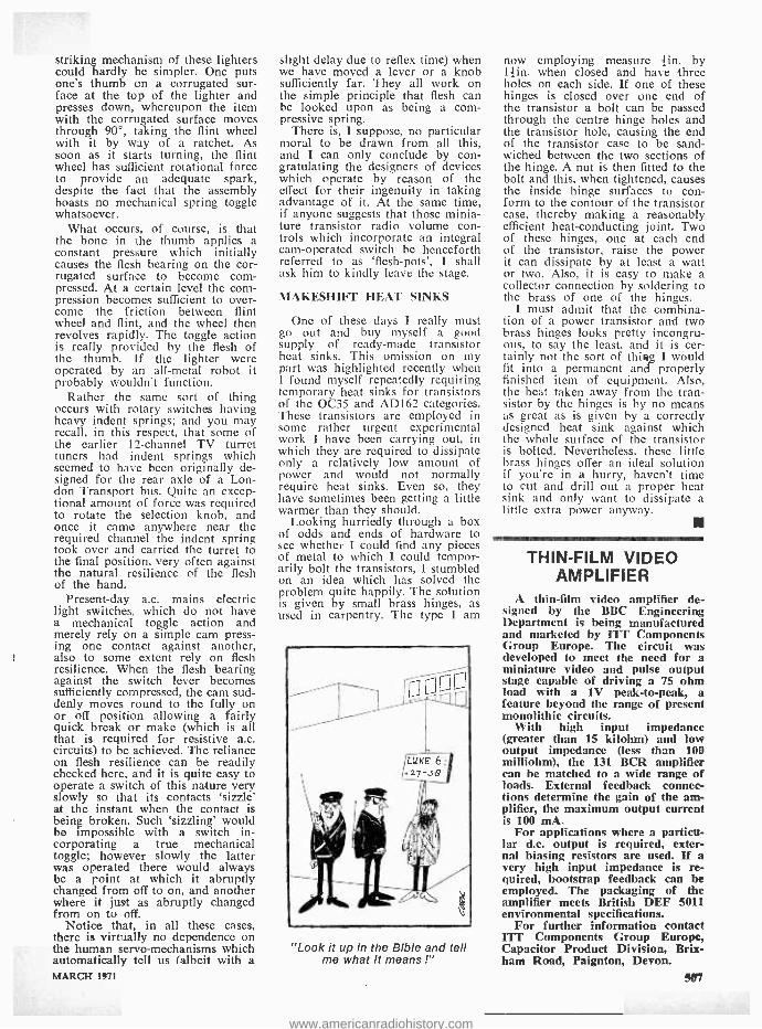
striking mechanism of these lighters could hardly be simpler. One puts one's thumb on a corrugated sur- face at the top of the lighter and presses down, whereupon the item with the corrugated surface moves through 90 °, taking the flint wheel with it by way of a ratchet. As soon as it starts turning, the flint wheel has sufficient rotational force to provide an adequate spark, despite the fact that the assembly boasts no mechanical spring toggle whatsoever.
What occurs, of course, is that the bone in the thumb applies a constant pressure which initially causes the flesh bearing on the cor- rugated surface to become corn - pressed. At a certain level the com- pression becomes sufficient to over- come the friction between flint wheel and flint, and the wheel then revolves rapidly. The toggle action is really provided by the flesh of the thumb. If the lighter were operated by an all -metal robot it probably wouldn't function.
Rather the same sort of thing occurs with rotary switches having heavy indent springs; and you may recall, in this respect, that some of the earlier 12- channel TV turret tuners had indent springs which seemed to have been originally de- signed for the rear axle of a Lon- don Transport bus. Quite an excep- tional amount of force was required to rotate the selection knob, and once it came anywhere near the required channel the indent spring took over and carried the turret to the final position, very often against the natural resilience of the flesh of the hand.
Present -day a.c. mains electric light switches, which do not have a mechanical toggle action and merely rely on a simple cam press- ing one contact against another, also to some extent rely on flesh resilience. When the flesh bearing against the switch lever becomes sufficiently compressed, the cam sud- denly moves round to the fully on or off position allowing a fairly quick break or make (which is all that is required for resistive a.c. circuits) to be achieved. The reliance on flesh resilience can be readily checked here, and it is quite easy to operate a switch of this nature very slowly so that its contacts 'sizzle' at the instant when the contact is being broken. Such 'sizzling' would be impossible with a switch in- corporating a true mechanical toggle; however slowly the latter was operated there would always be a point at which it abruptly changed from off to on, and another where it just as abruptly changed from on to off.
Notice that, in all these cases, there is virtually no dependence on the human servo -mechanisms which automatically tell us (albeit with a MARCH 1971
slight delay due to reflex time) when we have moved a lever or a knob sufficiently far. They all work on the simple principle that flesh can be looked upon as being a com- pressive spring.
There is, I suppose, no particular moral to be drawn from all this, and I can only conclude by con- gratulating the designers of devices which operate by reason of the effect for their ingenuity in taking advantage of it. At the same time, if anyone suggests that those minia- ture transistor radio volume con- trols which incorporate an integral cam -operated switch be henceforth referred to as 'flesh- pots', I shall ask him to kindly leave the stage.
MAKESHIFT HEAT SINKS
One of these days I really must go out and buy myself a good supply of ready -made transistor heat sinks. This omission on my part was highlighted recently when I found myself repeatedly requiring temporary heat sinks for transistors of the 0C35 and AD162 categories. These transistors are employed in some rather urgent experimental work I have been carrying out, in which they are required to dissipate only a relatively low amount of power and would not normally require heat sinks. Even so, they have sometimes been getting a little warmer than they should.
Looking hurriedly through a box of odds and ends of hardware to see whether I could find any pieces of metal to which I could tempor- arily bolt the transistors, I stumbled on an idea which has solved the problem quite happily. The solution is given by small brass hinges, as used in carpentry. The type I am
"Look it up in the Bible and tell me what it means !"
now employing measure tin. by 1 }in. when closed and have three holes on each side. If one of these hinges is closed over one end of the transistor a bolt can be passed through the centre hinge holes and the transistor hole, causing the end of the transistor case to be sand- wiched between the two sections of the hinge. A nut is then fitted to the bolt and this, when tightened, causes the inside hinge surfaces to con- form to the contour of the transistor case, thereby making a reasonably efficient heat -conducting joint. Two of these hinges, one at each end of the transistor, raise the power it can dissipate by at least a watt or two. Also, it is easy to make a collector connection by soldering to the brass of one of the hinges.
I must admit that the combina- tion of a power transistor and two brass hinges looks pretty incongru- ous, to say the least, and it is cer- tainly not the sort of thing I would fit into a permanent and properly finished item of equipment. Also, the heat taken away from the tran- sistor by the hinges is by no means as great as is given by a correctly designed heat sink against which the whole surface of the transistor is bolted. Nevertheless, these little brass hinges offer an ideal solution if you're in a hurry, haven't time to cut and drill out a proper heat sink and only want to dissipate a little extra power anyway.
THIN -FILM VIDEO AMPLIFIER
A thin -film video amplifier de- signed by the BBC Engineering Department is being manufactured and marketed by ITT Components Group Europe. The circuit was developed to meet the need for a miniature video and pulse output stage capable of driving a 75 ohm load with a 1V peak -to -peak, a feature beyond the range of present monolithic circuits.
With high input impedance (greater than 15 kilohm) and low output impedance (less than 100 milliohm), the 131 BCR amplifier can be matched to a wide range of loads. External feedback connec- tions determine the gain of the am- plifier, the maximum output current is 100 mA.
For applications where a particu- lar d.c. output is required, exter- nal biasing resistors are used. If a very high input impedance is re- quired, bootstrap feedback can be employed. The packaging of the amplifier meets British DEF 5011 environmental specifications.
For further information contact ITT Components Group Europe, Capacitor Product Division, Brix - ham Road, Paignton, Devon.
507
www.americanradiohistory.com

LATE NEWS
I finir, GMT Frequencies kHz
* AMATEUR BANDS
TOP BAND At the time of writing, Trans- Atlantic signals
continue to be heard on this band mainly on Sunday mornings from around 0430 to 0730. CW signals from across the `pond' heard in mid- January in- cluded W 1 BB (1804 at 0625), W 1 BHQ (1806 at 0658). W1HGT (1804 at 0515), W1PL (1802 at 0650) and W9UCW (1808 at 0200). - See Last Look Round.
IRAN EP2BQ has been heard on 3795 SSB at 1830 and
EP2DX using SSB at 1920 on the same frequency.
SENEGAL REPUBLIC 6W8DY has been heard using 3793 SSB at 0728.
3799 SSB at 2045 and using 7081 SSB at 2110. 6W8GE is reported QRV often on 21025 and 21040 from 1800 to 1900 and from 2000 to 2100.
LESOTHO 7P8AB heard on 21020 at 1935 using CW, on
21314 SSB at 1807 and also on 28600 SSB at 0959. 7P8AZ heard on 21212 SSB at 1601 and also on 21270 SSB at 1824.
FRENCH GUIANA FY7YR has been heard on 14110 SSB at 2030;
FY7AE on 14173 SSB at 0607 and on 28609 SSB at 1119 and 1355; FYOZO on 21315 SSB at 1203; and FYONA on 28545 SSB at 1406.
BRITISH HONDURAS VPIJF heard on 28620 SSB at 1330 and VPIST on
14225 SSB at 0010.
* BROADCAST BANDS BRAZIL
ZYZ43 Radio Em. Paranaense, Curitba, has moved to the new channel of 9660 (7.5kW) from 9545. Schedule is from 0800 to 2100.
PRK9 Radio Inconfidencia, Belo Horizonte, may be heard around 2015 on 15190 (5kW). Schedule is from 0900 to 0300.
PRA8 Radio Clube Pernambuco, can often be logged on 11865 (7.5kW). Schedule is from 0900 to 0300, listen around 2030.
On the 1.f. bands, listen for ZYZ20 Rio de Janeiro on 4905 (5kW). Announces as "Radio Relogio" and may often be heard at good signal strength from around 0100 onwards. Schedule is 24 hours. Listen also for ZYX2 Radio Brazil Central, Goiania, on 4995 (5kW) around 0100 or so. Schedule is from 0800 to 0400.
CHAD Fort Lamy may be heard on 4904 (30kW) around
2000 with programmes of colourful local music and songs. Languages used are French, Arabic and various local dialects. Station identification is in French.
EQUATORIAL GUINEA Santa Isabel, Fernando Po (also spelt Poo) may be
heard around 2015 or so on 6250 (10kW). Languages used are Spanish and various local dialects, the schedule being from 0500 to 2300. Often heard with songs and music in the Spanish style.
SENEGAL Dakar may often be logged on the 4890 (25kW)
channel around 2000. Programme languages are French, Portuguese and local dialects. Schedule is from 0600 to 1000 and from 1800 to 2400 on this frequency.
Acknowledgements: - Our Listening Post, SCDX, ISWL.
WORLD RADIO -TV HANDBOOK
The 1971 edition of this well - known handbook was published and released in January. With a for- mat of 6 by 9 inches and comprising some 372 pages, the 1971 edition (25th) represents better value than ever at the £2.10 selling price.
The Handbook updates all the information that is currently avail- able on Radio and TV stations throughout the world.
In addition to the frequency lists and station information, the Handbook also features many arti- cles containing much information of interest to all who operate over the short waves. Such items as Broadcasts in English, Dx Pro- grammes, News in English, World Time Charts, Time Tables and many useful maps of various areas of the world.
The 1971 WRTH may be ob- tained from Modern Book Co., 19 Praed Street, London W.2, at £2.19 post paid. 508
LAST LeNnK ROUND TOP BAND TOPICS
For several years now interest in Dx working on this band has grown apace. Apart from G -Dx and Eu -Dx which attracts many to the band, there are those stalwarts who continue to get - or attempt to get - their CW signals across the Atlantic; this applying mainly to amateurs in the UK, Eire, W. Germany, Czechoslovakia and the USA. In addition to these countries however, signals have been heard from Canada, Venezuala, US Virgin Islands and Bermuda.
During the last `season' for intercontinental working (the `season' is approximately from mid -October to late February) activity has been greater than ever although conditions did not approach those of the previous `season'. In the main, signals from across the Atlantic tended to be just above the noise level although on occasions some were coming in at good signal strengths - `regulars' such as W 1 BB, W 1 HGT and K1PBW, but more of all this in a later issue.
THE RADIO CONSTRUCTOR
www.americanradiohistory.com

Gr /íI9 irmA in April issue of PRACTICAL WIRELESS
8-PAGE GUIDE IO
TEST INSTRUMENTS This illustrated eight -page supplement is a survey of current test gear for servicing radio and audio equipment. Though complete in itself, it will also provide a useful introduction to an important new series on servicing by H. W. Hellyer and Gordon J. King,
which starts in the following month's issue.
WORKSHOP OSCILLOSCOPE This Practical Wireless design enables you to see what is going on inside a circuit, including the examination of waveforms, distortion and pulses. You can make this versatile test instrument -readily available c.r.t. and other components. Even the case
is a stock item. Read all about it in the April issue.
MARCH 1971
HIGH IMPEDANCE VOLTMETER Winner of the Practical Wireless Project Autumn Trophy. With ranges of 1-10-100-1000V and input impedance of at least 3M S2. The cost is small, a
501íA meter and three 2N2926 transistors forming the basis of operation of this ingenious project. Full constructional details in the April Practical Wireless.
Plus other constructional features
PRACTICAL WIRELESS Aprii issue on sale Friday 5 March-17+p
509
www.americanradiohistory.com
£2.10p
THE MODERN BOOK CO
1971 WORLD RADIO -TV HANDBOOK A Complete Directory of International
Radio and Television
20 Solid State Projects for the Car & Garage R. M. Marston. £1.20p Postage 5p
Using an Oscilloscope D. W. Easterling. 70p Postage 5p
Guide to Broadcasting Stations Wireless World. 50p Postage 4p
Simple Short -Wave Receivers F. A. Baldwin. 80p Postage 5p
Colour Television with Particular Reference to the PAL System G. N. Patchett. £2.50p
HI -Fi Year Book 1971 Colin Sproxton. £1.00
Radio Valve & Transistor Data A. M. Ball. 75p
Postage 5p
Postage 10p
Postage 9p
We have the Finest Selection of English
Postage 9p
Transistor Audio & Radio Circuits Mullard. £1.50p Postage 5p
Transistor Electronic Organs for the Amateur Alan Douglas /S. Astley. £1.00 Postage 5p
The A.R.R.L. Antenna Book A.R.R.L. £1.50p
Electronics & Radio M. Nelkon & H. I. Humphreys. £1.50p
Postage 12p
Postage 10p
Transistor Manual J. F. Cleary. £1.05p
T.V. Fault Finding, 405/625 Lines J. R. Davies. 50p
Radio Communication Handbook R.S.G.B. £3.15p
Postage 9p
Postage 5p
Postage 25p
and American Radio Books in the Country
19 -21 PRAED STREET (Dept RC) LONDON W2 Telephone PADdington 4185
SIMPLE SHORT -WAVE RECEIVERS by F. A. Baldwin
* FOUR DESIGNS - 1, 2 and 3 Valves
* INTRODUCTION TO SHORT WAVE LISTENING -
14 Comprehensive Sections
* WORKSHOP PRACTICE
* SOLDERING NOTES
* RECEIVER AND BENCH POWER SUPPLIES
etc. etc. 140 Pages $Op Postage 5 ¡p
If you are interested in the hobby of receiver construction and short wave listening this is the book for you. It covers the whole field of s.w.l'ing from construction to operating - both Broadcast and Amateur bands. It explains how the cir- cuits work, how to assemble the parts, how to wire -up the circuits with point -to -point wiring diagrams, step -by- step instructions & how to test and operate the completed projects.
=MI
TO DATA PUBLICATIONS LTD 57 Maida Vale London W9 1SN Please supply copy(ies) of 'Simple Short Wave Receivers', Data Book No. 19
I enclose cheque /crossed postal order for
NAME
ADDRESS
BLOCK LETTERS PLEASE
510 THE RADIO CONSTRUCTOR
www.americanradiohistory.com
SMALL ADVERTISEMENTS Rate: 4p (9d.) per word Minimum charge 60p (12/ -)
Box No. 10p (2/ -) extra.
Advertisements must be prepaid and all copy must be received by the 4th of the month for insertion in the following month's issue. The Publishers cannot be held liable in any way for printing errors or omissions, nor can they accept responsibility for the bona fides of advertisers. (Replies to Box Numbers should be addressed to: Box No. -, The Radio Constructor, 57 Maida Vale, London, W9 1SN.
SERVICE SHEETS (1925 -1970) for Radios, Televisions, Transistors, Tape Recorders, Record Players, etc., with fault finding guide. Over 8,000 models available. S.A.E. list/enquiries. Hamilton Radio, 54 London Road, Bexhill, Sussex.
CONSTRUCTORS USED COMPONENTS. Parcels at 50p each, including postage, 50 assorted resistors. 50 assorted capacitors. 10 electrolytic capacitors. 10 assorted knobs. 5 assorted potentiometers. 20 assorted valve bases. Please state which parcel required. Broad- cast type twin gang variable capacitors at 18p each Speakers at 50p each. 7 inch, 5 inch, 51 x 3# inch elliptical. P & P. 18p. Box No. G142.
NEW CATALOGUE NO. 18, containing credit vouchers value 50p, now available. Manufacturers new and surplus electronic and mechanical components, price 23p post free. Arthur Sallis Radio Control Ltd., 28 Gardner Street, Brighton, Sussex.
VALVES. All at 13p postage paid. EB91, 6AG5, EL91, EL92, DK91, EF40, 3ML, 1S5, 141TH, U142, UBC41, UY41, 171DDP, 10F9, N142, U404,VR91, HL41DD, TH41, PEN45, X65, U14, TDD4, 6B4G, 41MP, 801 -A, VT136, VP41, HP4106, VT62. Box No. G143.
BUILD IT in a DEWBOX robust quality plastic cabinet 2in. x 2 }in. x any length. S.A.E. for details. D.E.W. Ltd., 254 Ringwood Road, Ferndown, Dorset. Write now - right now.
MINI MAINS PACK KIT. Safe double -wound trans- former, Si.rects, 1000µF and instructions for 9V, 120mA eliminator. Can be built to size of PP6 battery. UK 95p, post paid. S.A.E. list. Amatronix Ltd., 396 Selsdon Road, South Croydon, Surrey, CR2 ODE.
FOR SALE: Txing type variable capacitor, 50- 110pF, +in. spacing £1. Ditto, 75 +75pF, -'sin. spacing, 50p Tannoy P.A. Mic, £1.50. 1.5 - 3MHz Command re- ceiver, £2. Motor generator, 12V 4A in, 400V .05A out, £1.50. Eddystone 6 pin plug -in coil formers, Cat. 538, 13p. Type 3 T/P ink rollers, 25p bottle. 200ft. Super -8 cine reels, 25p. Box No. G144.
CONFIDENTIAL PRINTING /DEVELOPING. Free printing. Developing from 40p S.A.E. details. Mr. Bobker, 29 Chadderton Drive, Unsworth, Bury, Lancs.
"MEDIUM WAVE NEWS" Monthly during Dx season -Details from: K. Brownless, 7 The Avenue, Clifton, York.
(Continued on page 513) MARCH 1971
BENTLEY ACOUSTIC CORPORATION LTD. 38 Chalcot Road, Chalk Farm. The Old Police Station LONDON, N.W.I. Gloucester Road
01 -722 9090 LITTLEHAMPTON, Sussex Please forward all mail orders to Littlehampton PHONE 6743
57.40 .95 ECC84 .30 PC88 .52 PY88 .34 ACI57 .25 BY127 .18 6AT6 .20 ECC86 .28 PC88 .52 PY500 1.08 AD140 .38 BYZIO .26 6!30L2 .68 ECC86 .40 PC95 .63 PY800 AD149 .60 BYZ11 .25 6BR7 .79 ECC88 .35 PC97 .40 PY801
.38
.34 AD161 .46 BYZ12 .26 6ßW6 .72 EC0189 .48 PC900 .38 QQVO3/ ÁD162 .46 BYZ13 .26 6BW7 .6.5 ECF80 .33 PCC84 .32 10 1.20 ÁF114 .25 0A70 .16 61`23 .72 ECF82 .33 PCC85 .33 R19 .33 ÁF116 .15 0A79 .09 61,28 .70 ECF86 .65 PCC88 .49 018/20 .75 AF119 .23 OAgl .09 6L6GT .39 ECH42 .64 PC089 .48 019 1.73 ÁF121 .30 0Á90 .13 9D7 .78 ECH81 .29 PCC189 .49 026 .65 AF126 .18 0A91 .09 1001 - 1.25 ECH83 .40 PCF80 .30 U26 .59 AF139 .65 OA96 .09 I0F18 .35 ECH84 .38 PCF82 .33 U191 .63 AFI80 .48 0A200 .09 I2A6 .63 ECL80 .36 PCF84 .40 U301 .63 AF188 .55 OA202 .10 30015 .65 ECL82 .33 PCF88 .50 0801 .95 AF239 .38 0023 .38 30017 .80 ECL83 .62 PCF200 .67 UABC80 .33 BA102 .45 0024 .38 30018 .64 ECL88 .40 PCF801 .35 UBC81 .40 BA115 .14 O025 .38 30E5 .50 EF22 .63 PCF802 .45 UBF80 .29 BA116 .20 0026 .25 30FL1 .64 EF41 .50 PCF806 .64 UBF89 .34 BA129 .13 0028 .60 30FL2 .76 EF80 .23 PCH200 .62 U092 .35 BA130 .10 0035 .32 30E1.14 . -3 EF85 .29 POL82 .37 UCC84 .40 BC107 .13 0C36 .43 30LI5 .64 EF86 .32 PCL83 .60 UCC85 .37 BC108 .13 0C38 .43 30L17 .78 EF89 .25 PCL84 .38 UCF80 .42 BC113 .25 OCAS .10 30P4/30 .60 EF91 .17 PCL805/ UCH2I .60 BC118 .23 0045 .13 30P4MR .98 EF183 .30 85 .45 UCH42 .63 BCY10 .45 0046 .16 30P12 .69 EF184 .30 PC1.86 .43 UCH81 .33 BCYI2 .50 0070 .13 30PL1 .69 E1190 .38 PEN46DD UCL82 .35 BCY33 .20 0071 .13 30PL13 .78 EL34 .53 .75 UCL83 .50 BCY34 .23 0072 .13 DY86 /7 .29 EL41 .55 PFIl200 .59 ÚF41 .50 BCY38 .23 0074 .23 DY802 .48 EL84 .24 PL36 .48 ÚF80 .35 BCY39 .25 0075 .13 E88CC: .60 EL96 .35 P1.81 .48 UF86 .34 BCZ11 .38 0078 .16 EABC80 .33 EM80 .38 PL82 .33 UF86 .63 1313119 .46 0078D .16 EAF42 .50 EM81 .42 PL83 .33 UF89 .34 BFY50 .23 O081 .18 E1334 .20 EM84 .34 PL84 .33 UL41 .59 BFY51 .19 OC81D .13 EBOI .12 EM87 .38 PL500 .68 01.84 .33 BFY52 .20 0082 .13 EBC41 .48 EY51 .37 PL604 .68 UM80 .33 8F159 .25 0083 .20 EBC81 .33 EY8617 .33 PL608 1.40 UY41 .38 11E163 .20 0084 .24 EBF80 .34 5240 .40 P0.609 1.44 DY86 .29 BF173 .38 00123 .23 EBF83 .40 EZOO .23 PX4 1.18 AAI19 .15 8E180 .30 0C139 .23 EBF89 .32 EZ81 .24 Px25 1.18 AC113 .26 BY100 .18 0C169 .23 EC92 .35 111,112 .63 PY32/33 .50 AC127 .20 BY101 .15 00172 .36 ECC81 .19 KTW62 .63 PY81 .27 ÁC1.28 .20 BY105 .18 00200 .22 ECC82 .23 KT66 .83 PY82 .27 AC164 .25 BY114 .68 00202 .43 ECCO3 .23 KT88 1.70 PY83 .29 AC156 .20 BY126 .16 00203 .30
All goods are unused and boxed, and subject to the standard 90-day gua antes. Terme of business: Cash or cheque with order only. No C.O.D. orders accepted. Poet /packing charge 3p per item, subject to a minimum of 9p. All orders despatched same day by Bret class mall. Complete catalogue with conditions of aale 7p post paid. Any parcel insured against damage in transit for only 7p extra per order. Business hours 9 a.m. 5.30 p.m. Sat,. 9 a.m.-1 p.m. Littlehampton closed Bata.
TECHNICAL TRAINING in Radio, Television and
EST. 1891 Electronic Engineering First class opportunities in Radio and Electronics await the ICS trained man, Let ICS train YOU for a well -paid post in this expanding field. ICS courses offer the keen, ambitious man the opportunity to acquire, quickly and easily, the specialized training so essential to success. Diploma Courses in Radio, TV Engineering and Servicing, Colour TV Servicing, Electronics, Com- puters, etc. Expert coaching for: * C. &G. TELECOMMUNICATION TECHNICIANS CERTS * C. &G. ELECTRONIC SERVICING * R.T.E.B. RADIO AND TV SERVICING CERTIFICATE * RADIO AMATEURS EXAMINATION * RADIO OPERATOR CERTIFICATES Examination Students Coached until Successful. NEW SELF -BUILT RADIO COURSES Build your own 5 -valve receiver, transistor port- able, signal generator, multi -test meter -all under expert guidance. POST THIS COUPON TODAY and find out how ICS can help YOU in your career. Full details of ICS courses in Radio, Television and Electronics will be sent to you by return mail. Member of Association of British Correspondence Colleges.
INTERNATIONAL CORRESPONDENCE SCHOOLS 1
I Dept. 248, Intertext House, Stewarts Road, London, S.W. 8.
Name. ...Age ..
IBLOCK CAPITALS PLEASE
Address.-._._.. ._...__.._............_.__..__ .__._...._..__._._.
3.71 usssfmNm- s sow -soaaI
I
I
511
www.americanradiohistory.com

RADIO OP E RATORS There will be a number of vacancies in
the Composite Signals Organisation for experienced Radio Operators in 1971 and subsequent years.
Specialist training courses lasting approxi- mately eight months are held at intervals. Applications are now invited for the course starting in September 1971.
Salary Scales During training with free accommodation
provided at the Training School:- Age 21 £848 per annum
22 £906 99
23 £943 24 £981 25 and over £1,023 41
On successful completion of course: - Age 21 £1,073 per annum
22 £1,140 19
23 £ 1,207 24 £1,274 19
25 (highest £1,351 age point)
then by six annual increments to a maximum of £1,835 per annum.
Excellent conditions and good prospects of promotion. Opportunities for service abroad.
Applicants must be United Kingdom residents, normally under 35 years of age at start of training course, and must have at least two years operating experience, or PMG qualifications. Preference given to those who also have GCE `O' level or similar qualifications. Exceptionally well qualified candidates aged from 36 -40 may also be considered.
Interviews will be arranged throughout 1971.
Application forms and further particulars from:-
Recruitment Government
Officer (TRO 63) Communications
Headquarters, Oakley, Priors Road, CHELTENHAM, Glos., GL52 5AJ. Tel: Cheltenham 21491. Ext. 2270.
512
If you're a telecommunications man and match up
to the qualifications below cut yourself into a slice of. Britain's future
I I Air Traffic Control
Oi1E-
Radio I
Technician 1
in the fast -growing world of
I
I
I
Become a
Please send me an application form and details of how I can join the fascinating world of Air Traffic Control Telecommunications
Address
RCT/E4
Not applicable to residents outside the United Kingdom
To: A J Edwards, C Eng, MIEE, The Adelphi, Room 705, John Adam Street, London WC2N 6B0, row king your envelope 'Recruitment' M OEM - Sending this coupon could beyour first step to a job that's growing in importance every year.
The National Air Traffic Control Service needs Radio Technicians to install and maintain the vital electronic aids that help control Britain's ever -increasing air traffic.
This is the kind of work that requires not only highly specialised technical skills but also a well developed sense of responsibility, and candidates must be prepared to undergo a rigorous selection process. Those who succeed are assured a steadily developing career of unusual interest and challenge. Starting salary varies from £1044 (at 19) to £1373 (at 25 or over): scale maximum £1590 (higher rates at Heathrow). There is a good annual leave allowance and a non -contributory pension for established staff.
You must be 19 or over, with at least one year's practical experience in telecommunications, ('ONC" or 'C and G' qualifications preferred).
NATCS National Air Traffic Control Service
THE RADIO CONSTRUCTOR
www.americanradiohistory.com
SMALL ADVERTISEMENTS (Continued from page 511)
TOP TRANSISTORS: ACY22, BC108, BC109, BC168, BFY51, BFY52, BSY27, 0C45, 0071, 0072, 0C200, 0C201, 0C202, ZTX300, 2N706, 2N2926, 2N3702, 2N3703, 2N3705, 2N3706, 2N3708. Brand new, un- marked, fully tested. Only 9p each or 16 for £1. Money back gurantee. P. & P. 5p. J. M. King, (M), 17 Buckridge, Portpool Lane, London E.C.1.
JOIN THE INTERNATIONAL S.W. LEAGUE. Free services to members including Q.S.L. Bureau, Ama- teur and Broadcast Translation, Technical and Identifi- cation Dept. -both Broadcast and Fixed Stations, DX Certificates, contests and activities for the SWL and transmitting members. Monthly magazine, Monitor, containing articles of general interest to Broadcast and Amateur SWLs, Transmitter Section had League affairs, etc. League supplies such as badges, headed notepaper and envelopes, QSL cards, etc., are available at reasonable cost. Send for League particulars. Mem- bership including monthly magazines, etc., £1.75 per annum. Secretary ISWL, 1 Grove Road, Lydney, Glos., GL15 5JE.
FOR SALE: Keilcraft model patrol boat, 40in., with Taplin Twin engine. Twin rudders with steering motor fitted. Throttle control for R/C also fitted. Superstructure requires completing ' and R/C gear installing. With Raven R/C four channel reed Tx and Rx. £60 o.n.o. Also P.A.C. kit for 57in. span Tiger Moth, £12. Box No. G146.
POSTAL ADVERTISING? This is the Holborn Service. Mailing lists, addressing, enclosing, wrappering, fac- simile letters, automatic typing, copy service, campaign planning, design and artwork, printing and stationery. Please ask for price list. -The Holborn Direct Mail Company, Capacity House, 2 -6 Rothsay Street, Tower Bridge Road, London, S.E.1. Telephone: 01- 407 -1495.
FOR SALE: Cossor 1045 double beam scope, Mk II. Surplus to requirements. In daily use. Complete with instruction service manual. £18. Box No. G147.
WANTED: Radio Constructor magazines. Any dates (not bound). Reasonable prices. All letters acknow- ledged. Box No. G148.
WORLD DX CLUB covers all aspects of SWLing on kmateur and Broadcast Bands through its monthI) bulletin "Contact ". Membership costs £ 1.38 a year Enquiries to Secretary, WDXC, 11 Wesley Grove. Portsmouth, Hants., P03 5ER.
FOR SALE: International Encyclopedia of Stamps, published by IPC Magazines Ltd. Vol. 1, parts 1 to 14. Vol. 2, parts 1 to 13. Cover price 23p each part. Will sell at £2 per volume. Box. No. G149.
TO CLEAR; Life World Library and Life Sunday Times World Library. All at 50p post paid. South - East Asia, Israel, Scandinavia, Tropical Africa, Greece, Mexico, Russia, Italy, Britain, Japan, Brazil. France, India & Germany. Box No. G150.
FREQUENCY LIST TRANSFERS. We have a limited supply of sheets of Dial Frequency Transfers in black. Short Wave frequencies 1.8Mc /s to 32Mc /s and 144Mc /s to 146Mc /s. Includes amateur band marker frequencies at 100kc /s points and other short wave frequencies from 2 to 32Mc /s at every 500kc /s points. Each frequency is repeated. Two sheets for 5p, five sheets for 10p, postage 2f p. Data Publications Ltd., 57 Maida Vale, London W9 1SN.
(Continued on page 515) MARCH 1971
RSGB BOOKS FOR YOU RADIO COMMUNICATION
HANDBOOK 832 pages of everything in the science of radio communication. The Handbook's U.K. origin en- sures easy availability of components. Complete coverage of the technical & constructional fields. A superb hard -bound volume. £3.50 post paid
AMATEUR RADIO TECHNIQUES By Pat Hawker, G3VA
Now in its third edition. A source of many useful circuits and aerials incorporating the latest ama- teur techniques. Contains 208 pages and nearly 500 diagrams. £1.13 post paid
A GUIDE TO AMATEUR RADIO By Pat Hawker, G3VA
Fourteenth edition. 100 pages. The new edition of this indispensable aid to all who want to know more about amateur radio. Designed to assist the newcomer to this unique hobby. Revised and expanded. 47p post paid
These are three of a complete range of technical publications, log books and maps, all obtainable from:
RADIO SOCIETY OF GREAT BRITAIN 35 DOUGHTY STREET, LONDON, WC1N 2AE
FREE TO AMBITIOUS ENGINEERS THE LATEST EDITION OF ENGINEERING OPPORTUNITIES
SEND FOR YOUR FREE COPY TO -DAY ENGINEERING OPPORTUNITIES is a highly informative 74 page guide to the best paid engineering posts. It tells you how you can quickly prepare at home for a recognised engineering qualification and outlines a wonderful range of modern Home Study Courses in all branches of Engineering. This unique book also gives full details of the Practical Radio & Electronics Courses administered by our Specialist Electronics Training Division - explains the benefits of our free Appointments and Advisory service and shows you how to qualify for five years promotion in one year.
'SATISFACTION OR REFUND OF FEE' TERMS We give a written agreement that if after completing one of our courses, you do not pass your examination or are dissatisfied in any other way, we will refund your complete fee.
PRACTICAL EQUIPMENT INCLUDING TOOLS The specialist Electronics Division of B.I.E.T. NOW offers you s real laboratory training at home with all the practical equipment you need. plus Basic Practice and Theoretical Courses for beginners in Radio, TV, Electronics, etc.
BRITISH INSTITUTE OF ENGINEERING TECHNOLOGY Dept. (480D) Aldermaston Court, Reading RG7 4PF -- SEND OFF THIS COUPON TO -DAY I - - -,
Tick subjects that interest you: AMSE (Elec) City & Guilds Certificate RTEB Certificate Radio Amateurs' Exam DMG Certificate Colour TV Electronic Engineering Computer Electronics Radio and TV Servicing Practical Electronics Practical TV & Radio Please send booklets & full information without cost or obligation.
NAME AGE ..................
ADDRESS
I To: BIET Dept. 4«OD, Aldermaston Court, Reading RG7 4PF
513
www.americanradiohistory.com
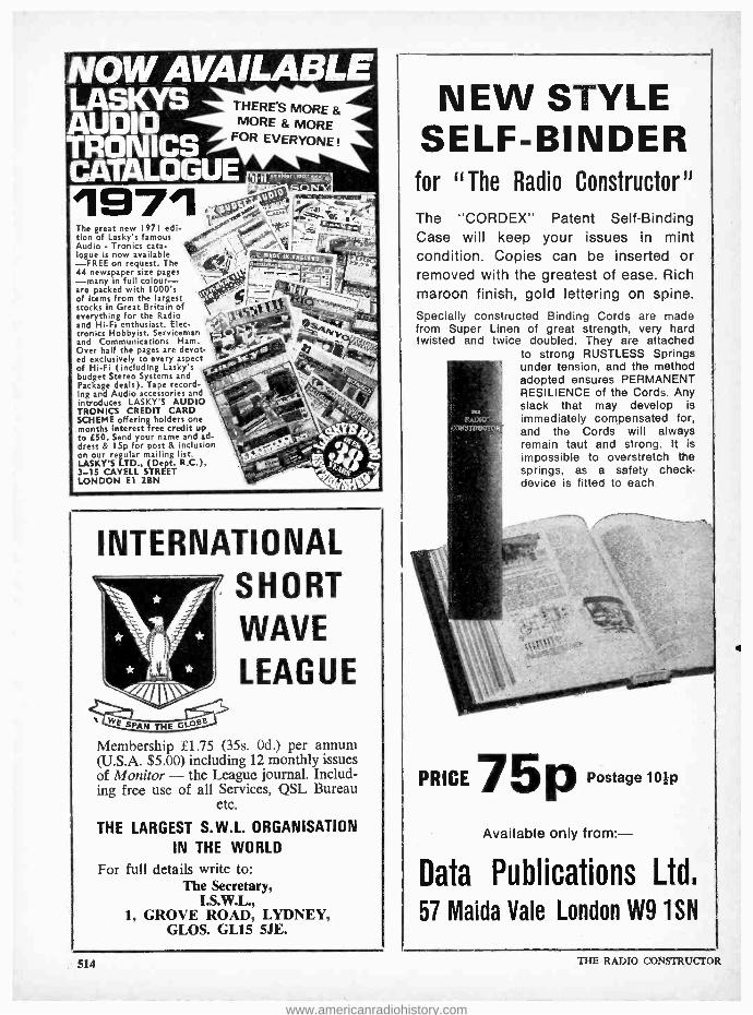
r
1971 The great new 1971 edi- tion of Lasky's famous Audio - Tronics cata- logue is now available -FREE on request. The 44 newspaper size pages -many in full colour - are packed with 1000's of items from the largest stocks in Great Britain of everything for the Radio and Hi -Fi enthusiast. Elec- tronics Hobbyist. Serviceman and Communications Ham. Over half the pages are devot- ed exclusively to every aspect of Hi -Fi (including Lasky's budget Stereo Systems and Package deals). Tape record- ing and Audio accessories and introduces LASKY'S AUDIO TRONICS CREDIT CARD SCHEME offering holders one months interest free credit up to LSO. Send your name and ad- dress & 15p for post & inclusion on our regular mailing list. LASKY'S LTD., DepPt. R.C.), 3 -15 CAVELL STREET LONDON El 2BN
INTERNATIONAL SHORT WAVE
LEAGUE
Membership £1.75 (35s. Od.) per annum (U.S.A. $5.00) including 12 monthly issues of Monitor - the League journal. Includ- ing free use of all Services, QSL Bureau
etc.
THE LARGEST S.W.L. ORGANISATION
IN THE WORLD
For full details write to: The Secretary,
LS.W.L., 1, GROVE ROAD, LYDNEY,
GLOS. GL15 53E.
514
NEW STYLE SELF- BINDER for "The Radio Constructor"
The "CORDEX" Patent Self- Binding Case will keep your issues in mint condition. Copies can be inserted or removed with the greatest of ease. Rich maroon finish, gold lettering on spine.
Specially constructed Binding Cords are made from Super Linen of great strength, very hard twisted and twice doubled. They are attached
to strong RUSTLESS Springs under tension, and the method adopted ensures PERMANENT RESILIENCE of the Cords. Any slack that may develop is immediately compensated for, and the Cords will always remain taut and strong. It is impossible to overstretch the springs, as a safety check - device is fitted to each.
PRICE 75I Postage 1Oip
Available only from:-
Data Publications Ltd,
57 Maida Vale London W9 1SN
THE RADIO CONSTRUCTOR
www.americanradiohistory.com

SMALL ADVERTISEMENTS (Continued from page 513)
FOR SALE: Specialist stamp collection. Space, Rai- way Centenary, ITU, IGY, etc. issues. Catalogue value approx. £150. Offers? S.A.E. for details. Another collection of early Space issues £25 o.n.o. Small general collection at £5. Box No. G151.
FREE GIFT when you request our quality stamps, supplied on approval. Generous discounts. Details from: Watson's Philatelic Service, 6 Beech Avenue Brentwood, Essex.
WANTED; Marine type sextant. Details & price to Box No. G152.
ARE YOU A MOTORING ENTHUSIAST? The Seven - Fifty Motor Club caters for all types of motor sport racing, rallies, hill climbs, etc. Monthly Bulletin free to members. For full details write to: The General Secretary, Colin Peck, "Dancer's End ", St. Winifred's Road, Biggin Hill, Kent.
FOR SALE: Pye Ranger 2M Tx. Needs converting. With valves and power supply. £6 plus carriage. Box No. G153.
IF YOU HAVE ENJOYED A HOLIDAY on the Nor- folk Broads, why not help to preserve these beautiful waterways. Join the Broads Society and play your part in determining Broadlands future. Further details from: -The Hon. Membership Secretary, The Broads Society, "Icknield ", Hilly Plantation, Thorpe St. Andrew, Norwich, NOR 85S,
HOLIDAY ACCOMMODATION. Burwood Lodge Hotel, Dawlish Road, Teignmouth, S. Devon. Espe- cially for parents with young children. Facing south, on the cliffs, direct access by private path to sea. Mothers' kitchen, automatic washing machines, baby listening service. Licensed lounge. Ample free parking.
CRYSTALS. Marine frequencies. 2381, 2089, 2306, 2182, in holders with tin. pin spacing £2 each. Box No. G154.
RECITALS OF RECORDED MUSIC. The second Saturday evening of each winter month. Next recital: Saturday, March 13th, 1971, 8 p.m. Woodford Green United Free Church, Woodford Green, Essex. Bus routes 20, 20A, 179 and 275 alight at "The Castle" stop.
RELAYS. Sigma type 72A0Z, octal base, £1.50; Carpen- ter, polarised, £1; D164816, £1.50. Box No. G155.
11111D, MUSICAL MIRACLES
WAA -WAA PEDAL. Complete kit of all parts. robust cabinet, mechanism & instructions. Huge sales, well proven design. ONLY L2.45 complete. Or built & tested L4.75 post free. RHYTHM BOX. Build your own from our pre -built electronic circuit modules, e.g box giving waltz, foxtrot, etc. costs under L17. ORGAN PERCUSSION units L14. Bass pedal and other fascinating effects, fuzz, tremolo, etc. Send s.a.e. for list. D.E.W. LTD. 254 Ringwood Road, FERNDOWN, Dorset
RADAR SPOTTER Prevention is best - YOU know it
makes sense! Use our unique non -radiating legal radar receiver. Gives early warning of Radar Speed Traps up to I} miles on motorways. Completely self contained (no wiring). Compact, clips on to sun visor. Weighs only 101 ozs.
BE SAFE, NOT SORRY - ORDER NOW. L13.7S C.O.D. 30p extra. BELDING á BENNETT LTD. (Box 38) 45 Green Lane, Purley, Surrey. For full oetails Tel: 01-688 3255 or 01-660 2896 or send 4p in stamps. Callers welcome by appointment.
MARCH 1971
PLAIN -BACKED NEW STYLE
SELF -BINDERS for your other magazines
(max. format 71" x 9} ")
The "CORDEX" Patent Self- Binding Case will keep your copies in mint condition. Issues can be inserted or removed with the greatest of ease. Specially constructed Binding cords are made from Super Linen of great strength, very hard twisted and twice doubled. They are attached to strong RUSTLESS Springs under tension, and the method adopted ensures PERMANENT RESILI- ENCE of the Cords. Any slack that may develop is immediately compensated for, and the Cords will always remain taut and strong. It is impossible to over- stretch the springs, as a safety check - device is fitted to each.
COLOURS: MAROON OR GREEN (If choice not stated, colour available will be sent)
PRICE 70 p Postage 102p
Available only from:-
Data Publications Ltd. 57 Maida Vale London W9 1 SN
515
www.americanradiohistory.com

CHASSIS and
CASES by
CASES HAMMERED FIN SHR Type Size Price Type Size Price N 8x6x2" [1.05 W 12x7x7" E2.00 N 6x6x3" £1.00 W 15x9x8" E2.70 N 4x4x2" 65p Y 8x6x6" £1.65 U 4x4x4" 65py Y 12x7x7" [2.60 U 5 }x4 }x4}" £1.00 Y 13x7x9" E2.90 U 8x6x6" E1.30 Y I5x9x7" E3.00 U 91x7]x3} £1.40 Z 17x10x9" L4.15 U 1 5x9x9" E2.80 Z I9x10x8I" E4.50 W 8x6x6" L1.30 *Height Type N has removable bottom, Type U re- movable bottom or back, Type W removable front, Type Y all screwed construction, Type Z removable back and front. Plus p. & p.
H. L.SMITH &CO. LTD. 287/9 Edgware Road
London W2 IBE TEL: 01 -723 5891
Type N
Type
-Type Y
Type Z
Type U
BLANK CHASSIS FOUR -SIDED 16 SWG ALUMINIUM
Size 6x4x2" 7x4x1I" 7x5x2" 8x4x2" 83x5 }x2" 9x7x2" 10x4x2 " 12x4x2 " I2x5x3"
Price
34p 33p 40p 38p 44p SOp 50p 55p 66p
Base Size 17p 10x8x2 }" 18p 12x7x2 }"
12x9x2 " 13x8x2I" 14x7x3 ' 14x10x2 15x10x2 17x10x3"
19p 19p 21p 26p 21p 22p 26p
Price 66p 66p 76p 76p 80p 88p 92p L1.10
Base 30p 33p 38p 38p 36p 47p 50p 55p
TO FIT OUR CASES
7x5 x1}" 38p 21p 12x6 ¡x2" 60p 33p 7x5 x2" 43p 21p 14x8 x2" 74p 44p Ilx6}xII" 55p 30p 153x9Ix2I "94p 52p Ilxó x2" 55p 30p 17 x9 x2 "L1.05 59p
Plus post & packing PANELS: Any size up to aft. at 36p sq. ft. 16 s.w.g.
(18 s.w.g. 32p). plus postage and packing
'YU K AN1. SO PROFESS /OVAL THE' SELF - Splat i YVAWN AEROSOL ¿AY-
Get theSe a// drying GREY HAMMER
OR BLACK WRINKLE NOW (CRACKLE) 7cirrishes Yukan Aerosol spraykit contains 453g. line quality, durable easy instant Other Cohan Air
spray. No stove baking required. Hammers available in grey and blue, OryingAeroso /s,
9op can. pd. Modern Eggshell Black Wrinkle (Crackle) producing a 3D 453g. at Pop
textured finish. 90p cart. pd., all at 85p per push -bunon self -spray can at PCt d.
Also durable. treat and water resistant Black Matt finish i c /ode:
(339g. sell ¡spray cans only) 75p cart. Pd. c C
SPECIAL OFFER: One ca lus optional transferable snap -on bigger e"lica Grr
handle (value 25) for 96 n p
pd p,ay p ute / /ics: Gray.
p p Para .Choice 0113 self -a lain cglours /ue.
Pips ent tae ch car crossed
also available. to.
Please snares cheque or croaeed P.O. for total amount direct to: '- ;:?: " DEPT :N /2 YUKAN, 307a EDGWARE ROAD, LONDON W21BN I l We supply many Government Departments, Municipal Authorities. Institutes and Leading Industrial Organisations -We can supply you too. Now Brkish -.tee Open all day Saturday. Closed Thursday a/te/neons. even better tame.
Fingers The more 'fiddly' the job, the more you depend on your finger -tips. Make sure minor burns and blisters don't rob them of their skill. Apply BURNEZE, pronto! This unique scientific aerosol cools the heat out of a burn in just 8 seconds, anaesthetizes pain, reduces swelling. BURNEZE - the clever tip for burnt finger -tips. From chemists.
Potter & Clarke Ltd Croydon CR9 3LP
DATA BOOK SERIES DB5 TV FAULT FINDING
124 pages. Price 50p, postage 51p.
DB16 RADIO CONTROL FOR MODELS 192 pages. Price 75p, postage 71p-
DB17 UNDERSTANDING TELEVISION 512 pages. Price £1.88, postage 20p.
DB18 AUDIO AMPLIFIERS 128 pages. Price 53p, postage 51p.
DB19 SIMPLE SHORT WAVE RECEIVERS 140 pages. Price 80p, postage 51p.
I enclose Postal Order /Cheque for
NAME ..
ADDRESS
in payment for
(Please use Block Capitals for both name -and address)
Postal Orders should be crossed and made payableto Data Publications Ltd. Overseas customers please pay by International Money Order.
All publications are obtainable from your local bookseller. Data Publications Ltd., 57 Maida Vale, London W9 ISN
Please mention THE RADIO CONSTRUCTOR when writing to advertisers THE RADIO CONSTRUCTOR
www.americanradiohistory.com

4 eEd
O a+ ,
.Q
C7 ' C G 'zzzzzz 0~q
cc;
C
Z M:
tTn.53CifE3&3_ en Nt O N O O\ O r- r ^ r- M Cl N un V'1 un 00 M M M M M M N N Cl Cl N N
v h V v U v v v V y y 1 v O 0o f` r- oo OA O^ N -r O-. N M N ,, r 00 0 un o0 00 0o OA O` Oh AD00000O0OÑ 3X^O,ÑÑMMMMMfN+1 wwwwwwwww...,zzzzzzzzz
W co W 070.1 co p70.1 W (..NNNNNNNNN
m
,
° A^
z ¡y
O 0 E5 U C7 gi" gi C7 C7 U h ol h N on Nt hAD r- cc on Nt vi O^^ r- 00 0h oc 00 00 00 00 O O o0 00 00 AO VD ^ v, en en el N N N N M M r- r` r- N Cl Nt Cr., Oh O`
z z z z z z z z z z z z z z z z rl N Cl CA N N N N Cl N N N el Cl N Cl
ÛC7C7Û JC7CC7C7C7C7ó^oôóCj-C7C7C7C7C7C7 Oo00o^rno ó0o dnAorrn0^ M t` r o0 00 en `..0,... cn n n Ó O Ñ Ñ M e+Ni
el on
LL.< w
4-d< ol w+ + z z Z z z z z z Q .<11" <L1-' .<4.d Q Cl N N N N N N N
Q -
E
011
cc
° z O
Zr-
01 on 01 01 0l In on on un on un on un Ul On On Cl) on
N M4-^ Cl M N--. N M^ N^ N M -. O O O O M O O O -^ O O O ̂ ^ M M MAD vi V1 Vl vi r- r- r` r- r- l` r` r` M 0 0l un Cl) on Cl) on Cl) o1 Cl) un un on un on rn un O N OA N Cl N el Cl N N Cl Cl Cl Cl CA N N N V
h - - O O O r` M . con On v VD v un ... M st) N O O O N -- -- N M V1, r- oo O, O Q
M 7 V O O O O pp el 4"'
z z zzzzzzzvol CCI) lOnCppCnnO(p^p(nnOOOOD, N rl N N rl N N N N N N N N Ñ N Ñ Ñ Ñ Ñ Ñ
vl vl
vlvlvltivlvlvlvlvlvlvlvlvlvlvld¢ o M v o^ M o0 M 00 0 o M v v n V1 0
CO 00 ^ M n O O ri N vi N N N N M V1 00 00 0 O O O^ en '4" C V V h r` r` r` r 00 N N Cl M M M M M M M M M M M M M M M M zzzzzzzzzzzzzzzzzzz. N N N N N N N N N N N cl N N N Cl Cl N N
v v1 h V1 d Cl) Q d v d un Cl) on ln n rn v N(,1 AO r- M M r- 00 Oh Oh O Cl N M R r- 00 Oh O er N N M on Nt V OA VO AO AO M M 00 00 M M M 'c}' ,,c
N N N N rI N N M M MNt NI. et st NI- h vi v1 vi cr
N N N. N N N N N N N N N N N N N N N N n Ñ Ñ z N Ñ Ñ Ñ N Ñ Ñ Ñ Ñ Ñ Ñ Ñ Ñ Ñ Ñ Ñ Z
N
www.americanradiohistory.com

HENRY'S RADIO LIMITED ENGLAND'S LEADING ELECTRONIC CENTRES HI -FI COMPONENTS TEST PA. DISCOTHEQUE ELECTRONIC ORGANS MAIL ORDER
TRANSISTOR AMPLIFIERS NEW RANGES NOW IN STOCK
(Leaflets Ref. Nos. 6 & 8) Post etc. 20p (4/:) 4 -300 4 TR 9 Volt 900 mW. £1.75 (35/ -) 104 4 TR 9 Volt 1 Watt £2.12 (42/5) 304 4 TR 9 Volt 3 Watt £2.47 (49/5) 555 6 TR 12 Volt 3 Watt £2.75 (55/ -) PA7 6 TR 16 Volt 7 Wat £3.62 (72/5) 608 6 TR 24 Volt 10 Wat £4.12 (82/5) 410 4 TR 28 Volt 10 Wat £4.97 (99/5) MPA12 /3 6 TR 18 Volt 12 Watt £4.50 (90 / -) MPA12/15 6 TR 36 Volt 12 Watt £5.25 (105/ -) Z30 9 TR 30 Volt 20 Wat £3.75 (75/ -) PA25 10 TR (Special) 25 Watt £7.50 (150/ -) 250 30 Voh 40 Watt £5.47 (109/5) PASO 12 TR (Special) 50 Watt £9.50 (190/ -) 100 100W. with Power SJpply C45.00 post 45p (9/ -)
OPTIONAL POWER SUPPLIES Post, etc. 20p (4/ -) P.500 Switchable (One or Two) for 104, 304 £2.62 (52/5) PS.20 Switchable One or Two) for PA7 £3.47 (69/5) MÚ24 /40 Switchable (Ore or Two) for
MPA12 /3 or MPA12/15 £4.50 (90/ -) PZ5 for Z30 £3.97 (79/5) or PZ6 for Z30 £6.97 (139/5) PZ8 for Z50 [5.97 (119/5) Transformer £2.25 (45/ -) P11 for 608 £2.87 (57/5) P15 for 410 £2.62 (52/5) MÚ442 for one or two PA25, or one only for PASO [6.50 (130/ -)
HI -FI TO SUIT
EVERY POCKET
TEST EQUIPMENT FOR HOME, SCHOOL & PROFESSIONAL USE
FROM IOU SYSTEMS and a complete range of indi- vidual units in stock - Demonstra- tions all day - visit our new Hi -Fi Store. LOW CASH or CREDIT /HP TERMS (Credit terms from £30 purchase - callers only). FREE - Stock list No. 16/17 on request.
BEST VALUE IN U.K.
S I N C LA I R PROJECT 60 PACKAGE DEALS 2x230 amplifier, stereo 60 pre -amp. PZ5 power supply. £19.00 Carr. 40p. Or with PZ6 power supply £21.00, Carr. 40p. 2xZ50 amplifier, stereo 60 pre -anp, PZ8 power supply £21.50, Cop r. 40p. Transformer for PZ8 £2.25 extra. Any of the above with Active Filter unit add £4.87 or with pair 016 speakers add £16.00.
Also NEW FM TUNER Price £23.00
BUILD THIS VHF FM TUNER 5 MULLARD TRANSISTORS 300 kc /s BANDWIDTH. PRINTED CIRCUIT, HIGH FIDELITY REPRODUCTION. MONO AND STEREO. A popular VHF 0M Tuner for quality and reception of -nono and stereo. There is no doubt about it - VHF FM gives the REAL sound. All parts sold separately, Free leaflet Nos. 3 & 7. TOTAL £6.97 (E6.19.6) p.p. 20p (4/ -) Cabinet £1.00. Decoder Kit £5.97. Tun-
ing Meter £1.75. Mains unit (optional) Model PS900 £2.47149/51. Mains unit for Tuner and Decoder PS1200 £2.62 (52/5).
BUILD YOURSELF A QUALITY RADIO Excellent printed circuit design with lull power output. Fully tuneable on both MW /LW bands. 7 Mullard transistors. Fitted 5in. speaker. Room- filling power. Easy to build with terrific results. TwT- colour leathercloth cabinet with silvered frort. All local and continental stations. Complete detailed instructions. Ask far Unite No. 1. Total cost £0.98 p.p. 35p
All parts sold separately.
HENRY'S LATEST CATALOGUE
Latest edition. Now 350 pages.
* Components, Test Gear * Equipment, Modules * Special Offers, etc. etc. Everything for the constructor. Complete with 50p value dis- count voucher for use with purchase. Price 50p Post Paid Why not send away today 7
FREE! FREE! FREE! FREE! 8-page Transistor, IC, Diode Lists No.36. 20-page Organs to Build brochure No. 9. Decks & Hi -Fi Stock Lists No. 16/17. PA, Disco & Lighting List No. 18. Quotations for all Elec- tronics - send S.A.E. for Lists.
AF105 50k /volt multimeter (illus.). £8.50 p.p. 20p. Leather case £1.42 200H 20k /volt. £3.87 p.p. 20p Case 62p 500 30k /volt multimeter £8.87 p.p. 20p Leather case £1.50 THL33 2k /voh £4.12 p.p. 15p Leather case £1.15 7E65 Valve voltmeter £17.50 p.p. 40p SE250B Pocket pencil signal injector
£1.75 post paid SE500 Pocket pencil signal tracer
£1.50 post paid TE2OD (illus.) RF generator C15.00 p.p. 40p TE22D Matching audio generator
£17.00 p.p. 40p 7E15 Grid dip meter £12.50 p.p. 20p TO3 Scope 3" tube £37.50 p.p. 50p TE22 Audio generator £17.00 p.p. 40p
¡GET A COPY OF OUR LATEST CATALOG, FULL SPECIFICATIONS AND FURTHER RA'. ,_S!
NEW MINATURE LOW -COST AMPLIFIER MODEL 4-300
9 volt operated or mains unit optional transformer (MT98 70p (14/ -) ). 1 -10mV adjustable sensitivity. P/P output for 3-8 ohms. Fitted volume control and leads. Size 5h" x 11 }" x I ". Thousands of uses - takes magnetic, dynamic and crystal inputs direct. Output 300 mW - very high gain - built -in rectifier circuit. Complete with FREE leaflet No. 8.
Price £1.75 (35/ -) p &p 15p (3/ -)
STC TIME DELAY MODULE
Ideal for experimenters. educational projects as well as for practical uses. Delay adjustable 3-15 secs. Oper- ates 9-12 volts. Heavy Duty Relay Contacts. Complete with suggested applications sheet. Price £1.75 post paid
GARRARD TAPE DECK
Price £9.97
109.19.81
P&p 33p (ar-I
300ft. 3 1" Tape & Spool 40p (8/ -) 9 volt operated 2 -speed tape deck fitted Record /Replay 8 track and Erase /Bias Osc. Head. Complete with Oscillator /Record head cir- cuit Unit size 9" x 61" x 1+" and 2 }" below motor board. Takes up to 4" spools. Supplied brand new.
HENELEC SELF -POWERED PRE -AMPLIFIERS
SLIM MODERN DESIGNS USING THE LATEST SILICON TRAN- SISTORS, FET's and IC's. DIN SOCKETS, etc. fitted. Self powered. PUSH -BUTTON SELECTION - 20dB BASS & TREBLE BOOST & CUT.
All inputs provided plus TAPE RECORD and REPLAY. Specifically designed for use with PA25 and PASO Amplifiers. GOLD & SI_VER FINISH,
Mains operated. Supplied with all plugs, etc. ADJUSTABLE OUTPUT UP TO 1 VOLT.
+ FET9 /4. Mono with tuilt -in mic. mixer. Accepts any ceramic or crystal cartridge. Plus tuner, tape, etc. Price £12.50 p.p. 20p
+ FET154 STEREO (illus.) Magnetic cart. input, tuner, tape, etc. Beautiful stereo sound.
Price £16.50 p.p. 25p
Also suitable for use with any power amplifier. Suggested types: PA25, PA50, MPAt2 /3, MPA12/15.
25 WATT á 50 WATT SILICON AMPLIFIERS LOOK AT THE SPECIFICATIONS!
At full power 0.3`/ distortion. At full power -1dB11c /s to40kc /s Response -1 db 11 c/s to 100 kc /s. Rise time 2A sec. Short circuit proof. FREE LEAFLET Plus limiting cct. No. 25 on request
PA 25 10 trans s or all silicon differential input 400 mV sensitivity. 25 watts Rms into 8 ohms. Supplied with edge connector harness size 5" x 3" x 2 ". PA 50 12 trans's or version 50 watts Rms into 3 to 4 ohms. Size 5" x 3" x 4 ". MU 442. Power supply for one or two PA 25 or one PA 50.
PA25 £7.50 PA50 £9.50 MÚ442 £6.00 p.p. 20p each SIMPUCITY TO MOUNT - EASY TO USE - DESIGNED FOR DUALITY, PERFORMANCE AND PRICE.
All units no soldering - just edge connectors and plugs. AS SPECIFIED FOR MANY "PRACTICAL WIRELESS" 1970 PROJECTS
Electronic Components & High Fidelity Sales & Test Gear Centre Dernonstr,rtions Centre 356 EDGWARE ROAD, 354 EDGWARE ROAD, LONDON, W.2. LONDON, W.2. Tel : 01 -402 4736 Tel : 01 -402 5854 OPEN 9 a m to 6p m MONDAY' TO SATURDAY' 9 3
Electronic Organs. P A. & Discotheque Centre 309 EDGWARE ROAD, LONDON, W.2. Tel: 01 -723 6963
at to 1 p m THURSDAYS -
Mail Order and Industrial Sales Dept 303 EDGWARE ROAD, LONDON, W.2. Tel: 01- 723 1008 .9
OPEN ALL DAY SATURDAY
www.americanradiohistory.com


![Comp151 Construction & Initializationjohnmave126.github.io/.../p/lectures/constructor-destructor.pdf · Constructor: Introduction [comp151] 3 default constructor blank CD MD to CD](https://static.fdocuments.us/doc/165x107/5edae51709ac2c67fa687b6b/comp151-construction-initi-constructor-introduction-comp151-3-default-constructor.jpg)