The Progressive Trends in Design, Reliability and ... · The Progressive Trends in Design,...
12
The Progressive Trends in Design, Reliability and Maintainability Aspects of Naval Defense Equipments Kumaran. P. T DGM-D&E-Fire control systems, Naval systems II, Bharat Electronics, Bangalore, India Abstract— This paper is formulated after many experiences of the author in design, document, assemble, test and evaluation of the most modern naval defense equipments which are integrated on board many ships of the country. The objective of this paper is to provide the reader the various technologies which are employed in making the Reliability and Maintainability aspects of the defense equipments an easy task of the project. The paper also describes various trends which were used in the past, current scenarios and also aiming the future perspectives in the area of Reliability and Maintainability. The reader would definitely enjoy the many experiences which are shared here and many of them will throw light for the current problems and future designs as well. It is worth to note that the entire application is in the arena of defense applications on naval platforms. Keywords— FEM, Qualification Testing, Environmental stress screening, Reliability, MTTR, MTBF, MTBCF, Maintainability, Quality, Fixture, Failure, Corrective action, vibration, Shock, EMI, EMC. I. INTRODUCTION The reliability and maintainability are the two important key elements in the defense electronics. ―Reliability‖ is the ability of a system or component to perform its required functions under stated conditions for a specified period of time. The need for R&M in the area of defense products is very crucial as it is considered to be prime importance for the life cycle of the product. The availability of working system on board ship is boon to the confidence of the fleet team. In this regard a comprehensive plan in providing quality design with highly reliable product is the duty of design team. The ―Maintainability‖ is the totality of all functions and features that represents ―ease‖ with which a product can be maintained in order to: o isolate defects or their cause, o correct defects or their cause, o repair or replace faulty or worn-out components without having to replace still-working parts, o prevent unexpected breakdowns, o maximize a product's useful life, o maximize efficiency, reliability, and safety, o meet new requirements, o make future maintenance easier, or o Cope with a changed environment. The Reliability is built in design phase and the product or the system undergoes many tests to evaluate the quality product sustains the E.S.S and Q.T methodologies as per defense guide lines and standards such as JSSS5555 (Indian MIL STD) and various MIL Standards. Through this paper, the experience gained in various naval projects has been shared highlighting salient points on the progressive trends in attaining the R&M of naval products and systems. II. DESCRIPTION OF EXISTING METHOD / TECHNIQUE RELATED TO WORK. A. Environmental Stress Screening: E.S.S are the tests carried out to bring out the process and workmanship defects which are present in the component / PCB / Module level subassemblies and assemblies before they are integrated in the assembly line for product / equipment manufacturing. These ESS tests are formulated by DQAN guidelines and are executed as a part of system while manufacturing. B. Environmental Tests E.T are the tests carried out to bring out the defects due to design and engineering which are present in the component / PCB / Module level subassemblies and assemblies after they are integrated in the assembly line as a product / equipment. These ET tests are formulated by JSS 55555 guidelines and are executed as a part of Qualification Tests after complete manufacturing and before offering to the customer and inducting on the naval platforms. C. EMI/EMC tests as per MIL STD 461 D/E EMI/EMC are the tests carried out to bring out the Electromagnetic Interferences and compatibility issue and defects due to components manufacturing, process and workmanship standards , design and engineering flaws which are present in the component / PCB / Module level subassemblies and assemblies after they are integrated in the assembly line as a product / equipment. These tests are formulated and governed by MIL STDs and DQAN guidelines and are executed as a part of Qualification Tests after complete manufacturing and before offering to the International Journal of Engineering Research & Technology (IJERT) ISSN: 2278-0181 www.ijert.org IJERTV3IS100781 (This work is licensed under a Creative Commons Attribution 4.0 International License.) Vol. 3 Issue 10, October- 2014 846
Transcript of The Progressive Trends in Design, Reliability and ... · The Progressive Trends in Design,...
The Progressive Trends in Design, Reliability and
Maintainability Aspects of Naval Defense
Equipments
Kumaran. P. T DGM-D&E-Fire control systems, Naval systems II,
Bharat Electronics,
Bangalore, India
Abstract— This paper is formulated after many experiences
of the author in design, document, assemble, test and
evaluation of the most modern naval defense equipments which
are integrated on board many ships of the country. The
objective of this paper is to provide the reader the various
technologies which are employed in making the Reliability and
Maintainability aspects of the defense equipments an easy task
of the project. The paper also describes various trends which
were used in the past, current scenarios and also aiming the
future perspectives in the area of Reliability and
Maintainability. The reader would definitely enjoy the many
experiences which are shared here and many of them will
throw light for the current problems and future designs as
well. It is worth to note that the entire application is in the
arena of defense applications on naval platforms.
Keywords— FEM, Qualification Testing, Environmental stress
screening, Reliability, MTTR, MTBF, MTBCF, Maintainability,
Quality, Fixture, Failure, Corrective action, vibration, Shock,
EMI, EMC.
I. INTRODUCTION
The reliability and maintainability are the two important
key elements in the defense electronics. ―Reliability‖ is the
ability of a system or component to perform its required
functions under stated conditions for a specified period of
time.
The need for R&M in the area of defense products is very
crucial as it is considered to be prime importance for the life
cycle of the product. The availability of working system on
board ship is boon to the confidence of the fleet team. In
this regard a comprehensive plan in providing quality
design with highly reliable product is the duty of design
team. The ―Maintainability‖ is the totality of all functions
and features that represents ―ease‖ with which a product can
be maintained in order to:
o isolate defects or their cause,
o correct defects or their cause,
o repair or replace faulty or worn-out components
without having to replace still-working parts,
o prevent unexpected breakdowns,
o maximize a product's useful life,
o maximize efficiency, reliability, and safety,
o meet new requirements,
o make future maintenance easier, or
o Cope with a changed environment.
The Reliability is built in design phase and the product or
the system undergoes many tests to evaluate the quality
product sustains the E.S.S and Q.T methodologies as per
defense guide lines and standards such as JSSS5555 (Indian
MIL STD) and various MIL Standards.
Through this paper, the experience gained in various naval
projects has been shared highlighting salient points on the
progressive trends in attaining the R&M of naval products
and systems.
II. DESCRIPTION OF EXISTING METHOD /
TECHNIQUE RELATED TO WORK.
A. Environmental Stress Screening: E.S.S are the tests carried out to bring out the process and
workmanship defects which are present in the component /
PCB / Module level subassemblies and assemblies before
they are integrated in the assembly line for product /
equipment manufacturing. These ESS tests are formulated
by DQAN guidelines and are executed as a part of system
while manufacturing.
B. Environmental Tests
E.T are the tests carried out to bring out the defects due to
design and engineering which are present in the component
/ PCB / Module level subassemblies and assemblies after
they are integrated in the assembly line as a product /
equipment. These ET tests are formulated by JSS 55555
guidelines and are executed as a part of Qualification Tests
after complete manufacturing and before offering to the
customer and inducting on the naval platforms.
C. EMI/EMC tests as per MIL STD 461 D/E
EMI/EMC are the tests carried out to bring out the
Electromagnetic Interferences and compatibility issue and
defects due to components manufacturing, process and
workmanship standards , design and engineering flaws
which are present in the component / PCB / Module level
subassemblies and assemblies after they are integrated in
the assembly line as a product / equipment. These tests are
formulated and governed by MIL STDs and DQAN
guidelines and are executed as a part of Qualification Tests
after complete manufacturing and before offering to the
International Journal of Engineering Research & Technology (IJERT)
IJERT
IJERT
ISSN: 2278-0181
www.ijert.orgIJERTV3IS100781
(This work is licensed under a Creative Commons Attribution 4.0 International License.)
Vol. 3 Issue 10, October- 2014
846

customer and inducting on the naval platforms. The
qualified units / products render interference-free platforms
and systems onboard ship.
D. Critical Failures In Various Projects
From various naval projects experience the types of
failures have been analyzed and solutions are described in
section 6 and 7
PARAMETER
S
TYPES OF FAILURES
Vibration and shock
• Loosening of screws, nuts
• Weld bead failures • Failure of joints
• Breakage of weak structures/Cross section
• Resonance of fixture
High
Temperature
• Component failure
• Soldering failure
Damp heat • Component failure
• Soldering failure
• PCB
Low
temperature
• Component failure
• Failure of Lubricants
• Soldering failure
Drip proof and
driving rain • Leakage through door
• Leakage through gaskets
• Leakage through fixing screws
Mold growth • Failure of samples
Corrosion • Failure of samples
EMI/EMC • Many types
III.PROPOSED TECHNIQUE
A.Vibration & Shock Test
1) Structural analysis: The structural
analysis for vibration and shock is a must in naval
equipments to carry out the simulation and to ascertain the
possible failures during vibration and shock. The fixture
design holds another important key in clearing these tests.
The fixture shall be ruggedized to take the vibration and
shock loads without yielding and amplifying the degree of
the test. The transmissibility in shock is very important
parameter in case of the units with rubber mounts, shock
mounts and wire mounts. The analysis is carried out using
the latest softwares such as ANSYS, Nastran 7,
HyperMesh 10 and 3D modeling using SolidWorks, Pro-E,
Ideas, Catia, Unigraphics etc.,
2) Modification to fixture: The
structural analysis for vibration and shock give important
details on probable failures on the fixtures which need to
be taken care in the fixture design. Such finer details help
in design and manufacturing to get the right fixture without
amplification of the vibration and shock excitations given
to the machine bed during the tests.
3) Modification to shock mount : The
structural analysis for vibration and shock give indirect
important details on the functioning of shock mount /
rubber mount / wire mount adopted in the unit design. The
transmissibility of vibration / shock can get amplified due
to improper selection of shock mounts. The mounts are
designed as spring elements with stiffness. Through FEM
analysis one can revise the shock mount selection when in
advance before the actual tests.
4) Fixing of components and screws :
The structural analysis for vibration and shock give
important details on probable failures on the fixtures which
needs to be taken care in the fixture design. Such finer
details help in design and manufacturing to get the right
fixture without amplification of the vibration and shoc
excitations given ti the machine bed during the test.
5) Proper fixing of components/parts :
The structural analysis for vibration and shock give
important details on probable failures on the fixing and
mounting methods which needs to be taken care in the
fixture design. Such finer details help in designer to modify
the fixing methods, changing the type of fasteners,
increasing welding area and bearing surfaces to withstand
shock and vibrations. The cross sections of the parts are
also modified in many cases to increase the stiffness and
provide more strength.
6) Soldering : The structural analysis
for vibration and shock give details on probable areas of
failures within the unit. In the electronic systems the
soldering of components needs to be given due attention so
that the transferred load on the PCB does not create failure
in the soldering joint. It is wiser to check there are no
soldering defects such as dry solder, improper and
inadequate joints in soldering areas.
7) Additional Support : The structural
analysis for vibration and shock reveals the need for
additional members to add strength and stiffness in the
weaker areas and cross section. In such cases the FEM as
to be repeated to revalidate that the required improvement
is obtained or not.
International Journal of Engineering Research & Technology (IJERT)
IJERT
IJERT
ISSN: 2278-0181
www.ijert.orgIJERTV3IS100781
(This work is licensed under a Creative Commons Attribution 4.0 International License.)
Vol. 3 Issue 10, October- 2014
847

Fig. 1 Snap Shots From Fem Analysis
8) Connectors, PCB’s, Cables : The
structural analysis for vibration and shock reveals the need
for change of connectors , additional members to add
strength and stiffness in the PCB‘s, weaker connector areas
, the need of proper anchoring of cables and wire.
9) Mounting of IC’s, PMC’s : The
structural analysis for vibration and shock reveals the need
for providing the proper support to IC‘s and PMC‘s.
Though these components are surface mounted and
soldered, the need for additional supports arises if the
weights of the components are slightly on the higher side.
B.High, Low Temperature & Damp Heat :
1) Thermal Analysis : The thermal analysis is a must
in naval equipments to carry out the thermal heat
dissipation simulation and heat flow to ascertain the
possible failures due to temperature during thermal test.
The boundary conditions, temperatures, conductivity of
medium, air flow and heat dissipation techniques are the
key factors in achieving the results which are more
accurate to close to reality. The analysis is carried out
using the latest softwares such as ANSYS, CFD, Solid
Works, Pro-E, Ideas, etc.,
Fig-2 Thermal analysis of typical electronic unit
2) Temperature Range : The temperature range is
crucial and this has to be considered correctly in thermal
analysis to ascertain the possible failures due to
temperature during thermal test.
3) Operating temperature : The operating
temperature range of components, special devices, PCB‘s,
COTs items are crucial and this has to be considered
correctly in thermal analysis to ascertain the possible
failures due to temperature during thermal test. The
selection of Industrial and COTs grade components while
designing needs to be verified before final design is firmed
up. The percentage failures of such devices in both low
temperature and high temperature are more in Thermal
tests.
4) Humidity Parameters : The humidity parameters
of components, special devices, PCB‘s, COTs items are
crucial and this has to be considered correctly in thermal
analysis / thermal test. The selection of Industrial and
COTs grade components while designing needs to be
verified before final design is firmed up. The percentage
failures of such devices in 95% RH specs are considerably
more.
5) Soldering : The Soldering quality is a main
concern in all electronic equipments. Refer III.A.6 for
further details.
6) Grounding : The grounding methodology to
dissipate the heat by conduction is also important in PCB‘s
and modules. The conduction shall be from components to
International Journal of Engineering Research & Technology (IJERT)
IJERT
IJERT
ISSN: 2278-0181
www.ijert.orgIJERTV3IS100781
(This work is licensed under a Creative Commons Attribution 4.0 International License.)
Vol. 3 Issue 10, October- 2014
848

PCB layers and continue with grounding / chasis. The
design shall be in such a way that these are addressed so as
to carry away a considerable amount of heat dissipation
through conduction and rest of the thermal aspects through
heat convection and radiations.
7) Fans and Blowers for forced convective cooling :
The cooling in electronic equipments is the most
complicated engineering aspect. The designer shall have all
the data regarding thermal requirements of components,
special devices, PCB‘s, COTs items in order to device the
most efficient method of cooling. Such data shall be
requested from OEM‘s during the design stages. The fan
type , air flow, delivery pressure fans in terms of CFM,
cross section of the air path, hindrances, position and
placement of fans/ blowers are the key factors which
decides the cooling methodology effective and efficient.
8) Dust filters : The dust filters used in the air flow
path generally gets clogged faster than expected period if
the environment is polluted. A periodic cleaning of the
filter is necessary and the same shall be addressed in the
maintenance manuals. The percentage blockage shall be
properly considered while designing as well as during
thermal analysis.
C.Drip Test :
1) Gasket : The Drip test is called in Environmental
Tests, in order to verify the system / unit functions in the
ship‘s environment. AC ducts and routings within ship will
be carrying either AC medium or chilled water lines and
prone to have condensation in their outer surface which
finally leads to dripping as water particles. The units shall
be designed with proper gaskets which take are off both
EMI/EMC and water tightness. Though the drip test is
conducted for 15 min, it is advisable to design the better
gaskets, gasket grooves with proper fasteners. The gaskets
of the chosen polymer shall have the required hardness for
adequate compression. The gasket material shall be
chosen for the correct medium, temperature, pressure and,
environment.
2) Gasket Groove depth : The gasket groove design
hand books may be referred for better design of gasket
cross section, groove depth, groove width etc. The gasket
groove finish and groove machining is critical to clear drip
test.
3) Surface Level of the gasket fixing : The gasket
groove is generally preferred on the cover for ease of
manufacturing. The surface level both on gasket groove
side and the housing side shall be in good planarity and
level so that the gasket compression after tightening will be
uniform and even.
4) Adhesive used to fix the gasket : The gasket
groove is generally preferred on the cover for ease of
manufacturing. The surface level both on gasket groove
side and the housing side shall be in good planarity and
level so that the gasket compression after tightening will be
uniform and even.
5) Fixing methodology : The pitch of the mounting
screws on the cover is important factor for good and even
gasket compression. The tapped hole for fixing the screws
on the housing side shall be blind and not a through hole.
The cover shall be made out of stiffer material and cross
section to avoid buckling effect which finally may lead to
leakage from the gap between cover and the housing.
6) Design of protection cover or hood : The
additional cover or hood helps in proving the drip test by
reducing the amount of drip falling on the covered area /
visible gasket joints. Such mechanism basically deflects
the drips by deflecting inggasket groove is generally
preferred on the cover for ease of manufacturing. The
surface level both on gasket groove side and the housing
side shall be in good planarity and level so that the gasket
compression after tightening will be uniform and even.
7) Leakage through screws : The gasket groove is
generally preferred on the cover for ease of manufacturing.
The surface level both on gasket groove side and the
housing side shall be in good planarity and level so that the
gasket compression after tightening will be uniform and
even.
D. Mold Growth And Corrosion :
1) Material properties : The material properties play
a vital role in clearing mold growth and corrosion tests.
Mold growth is carried out on painted parts and corrosion
test on components and raw materials. Usage of standard
proven materials is the simple solution to these tests.
2) Finish : The process qualities of finishing such as
primer, paint, varnish, electro-plating etc are verified in
this test. Qualified personnel with standard procedures for
finishing enhance the finish of the materials.
3) Test report for sub-contracted parts / modules :
The requirement of Test Reports shall be one of the
mandatory acceptance criteria clearing the various
processes. Thus the process verification as per standard
norms gets shifted to the vendor‘s premises.
Fig. 3 Test sample after corrosion test
International Journal of Engineering Research & Technology (IJERT)
IJERT
IJERT
ISSN: 2278-0181
www.ijert.orgIJERTV3IS100781
(This work is licensed under a Creative Commons Attribution 4.0 International License.)
Vol. 3 Issue 10, October- 2014
849

E. EMI/EMC
The EMI/EMC proving is another critical stage in naval
applications as the electromagnetic interferences can cause
severe damages on other units which are housed inside the
ship‘s compartment / above deck equipments. The
following key factors are to be addressed in proving the
reliability of the products is sustaining and clearing EMI /
EMC norms.
1) Cable assembly, Sleeving , heat shrink booting :
The cable assemblies are crucial from EMI point of view,
as the selection of contacts, wires, sleeving, heat shrinking
of boots, adhesives used for sealing, grounding of braids
on the connector shells, terminations of the wires, quality
of solders are the important factors where skills, processes
and workmanships plays importance.
2) Grounding : The grounding is another important
aspect. A proper grounding needs non ferrous contacts,
unpainted with electro-plating for perfect contacts. The
grounding shall start from grounding layer of the chosen
components to the PCB grounding layer. From PCB the
grounding shall extend to the card cage or chassis. All such
grounding shall get terminated to an earthing block. The
block shall be welded to the housing. The housing / cabinet
shall be connected to the floor / ground using proper braid
/grounding strip.
3) Honey comb filters, mesh lowers : The RF filters
and meshes used in air flow path of modules and units are
to be changed chosen properly while designing the units
for reliability. The frequency and band width required for
filtering depends on the components used inside the
module.
4) Blower : The operating frequency and the air flow
requirements are to be analyzed while selection of blower
during design stage. The noise level in db to be verified
before integrating with the system .The usage of
capacitances to bring down the spikes /EMI is a better
method to avoid or minimize noise levels.
5) Gasket type, material and adhesive : The gasket
(EMI) used shall be of the correct bandwidth and right
material of adequate silver particles as per standards for
EMI requirement. The gasket seating area shall be
conductive without any insulation layer. The adhesives
used for gasketing shall be conductive type. These
adhesive have limited shelf life and hence they are to be
used within specified time as per manufacturer‘s norms for
better functioning.
6) Mechanical gaps : In the entire engineering
aspect, the gaps existing between parts/ housing pose
EMI/EMC issues. If the area is large suitable mesh / cover
made out of EMI/EMC material can be designed and
integrated.
7) Earthing stud and strap : Earthing stud straps
generally made out non-ferrous metals such as brass which
are electroplated with tin/silver coating. The contact areas
shall be conductive without primer/painting/lacquer
coating. The usage ferrous materials lead to issues such as
hydrogen embrittlement, and galvanic corrosions. The
earthing braids chosen shall be made out of copper and
plated with tin/silver. The tightness of fasteners used is
also vital otherwise there is a possibility of arcing during
leakages.
8) Grounding of components and PCB’S : The
details are elaborated under Sec III.E.2.
9) Input power supply and filters : The input power
line shall have the desired level of filtering. The RFI filter
used shall be closed to the input line to avoid further
interferences from the wires in-between. The filters can be
integrated at PCB, Module and housing level.
10) Input power supply and filters :
The input power line shall have the desired level of
filtering. The RFI filter used shall be closed to the input
line to avoid further interferences from the wires in-
between. The filters can be integrated at PCB, Module and
housing level.
11) Requirement of inductors : The
usage of inductors for specific noise filtering is a general
practice to control / avoid EMI/EMC issues. These
inductors shall be secured and mounted properly and
junctions to be addressed properly through terminal boards.
12) Painting and masking : The
masking of primer and painting is very essential where
contacts are necessary for body grounding. The various
engineering documents shall clearly bring out the masking
areas of the part/Assembly levels. The covers, doors,
supports are provided with the EMI/EMC gaskets. The
gaskets needs conductive contact areas to suppress EMI
/EMC issues.
13) Fixing screws : Generally the
loose contacts and loose parts in electronic devices are
major concern and can cause noises at different
frequencies. Such of those assemblies shall be ensured for
proper tightening of screws. Refer section III.E.7 for more
details.
14) Grounding of PCB’s, card cage,
power supply and housing : The power supply modules
shall be analyzed properly for grounding methods specified
by OEM. The contact mechanism of power supply, its line
filters and gaskets are of importance. The power supply
shall be very tightly protected for EMI/EMC both inward
and outwards thro the lines. The cables shall be properly
shielded and booted for better functioning during ‗POWER
ON‘ conditions.
International Journal of Engineering Research & Technology (IJERT)
IJERT
IJERT
ISSN: 2278-0181
www.ijert.orgIJERTV3IS100781
(This work is licensed under a Creative Commons Attribution 4.0 International License.)
Vol. 3 Issue 10, October- 2014
850

15) Operating frequency of critical
components : The various components used in electronic
systems are of different frequency bandwidth , hence it is
wiser to list out the operating frequencies, noise level,
spikes etc and address these noise factors by incorporating
filters and RF gaskets at different levels.
16) Grounding TB’s : Usage of proper
grounding blocks is a good process in controlling
EMI/EMC issues. The state of the art TB‘s are available
with very good level of insulation and protection which
can be identified during design stage proactively to address
EMI/EMC issues.
17) Display and monitor specification
: Certain displays and monitors have specific noise levels
which cannot be filtered completely as the radiation in
some bandwidth is more than other frequencies. Usage of
special screens for filtering affects the quality of visibility
during manufacture of displays. The control can be only
through selection of displays and monitors and filtering at
input power lines.
Fig. 4 Test sample after corrosion test
IV. ANALYSIS – KEY RELIABILTY AND
MAINTAINABILTY FACTORS
The above chapters cover the design, reliability and
maintainability factors. The reliability is to be built into the
design by various methodologies. Progressive trends in day
to day life of electronic equipment manufacturer are
numerous in numbers. Some of the common trends are
illustrated below:
A. Access For Maintainability : Access for trouble
shooting, FDFL‘s, repairs and spare part management shall
be thought during the initial design itself. 3D visualization
through soft -wares provides greater advantages. The
maintainability mode can be graphically seen step by step
by advanced simulation packages eliminating issues of
maintainability.
B.Cable Routing : The cable routing and cable forming has
taken new edge making the cable forms outside on a board
and incorporating within the main housing. The cable
forms helps in maintaining process and workmanship in
standardized way than the conventional wiring. The signal
and power cable routing separation helps in EMI/EMC and
avoids noise being picked up video and signal cables.
C.CBD : The comprehensive configuration base line
diagram helps in understanding various issue levels of
different projects and different configurations used. CBD
table helps maintainer in locating FDFL‘s and replacement
of spares onboard.
D.Connectors – Shock Proof MIL Connectors : The above
deck connectors are facing the technology change from
aluminium material to brass, brass to steel and steel to
titanium. The shock proof MIL connectors are the demand
of these days where contact quality is very high. The
soldering and crimping quality with least-contact resistance
is the prime requirement in cabling of naval equipments.
E. Cooling & fans : Cooling of electronic equipment are
discussed with thermal analysis (REFER Sec III.B).
F. CSCI Identifications : Computer software controlled
modules are being identified with labels for ease of
maintenance during the life cycle of electronic units. These
identification provides easy removal of PCB‘s for software
updations as per SUM (Software user manuals).
G.Door Access : Various methods of door accessibility
have been invented so far. The most common door has
hinges on one side and locking on the other side with
suitable EMI/EMC gaskets. The rarely used ones are only
bolted or screwed type. The frequently operated doors are
being designed with latches for ease of removal.
H.EMI/EMC and filters : The selection of EMI/EMC
filters and their importance in illustrated in chapter III.E.
The recent trend is simulating the EMI/EMC through
software for the entire system and finding the optimal
solution for the same.
I.EMI/EMC on power and signal cables : The details have
been discussed under chapter III.E. The recent trend is that
laying of power and signal cables separately through
various branches and shielding the cables is now
technology driven.
J.Ergonomics : The Ergonomics (or human engineering) is
taken a front seat in design trend wherever human
involvement is more. The human engineering is described
to a greater extent in human engineering MIL STD hand
books. Ergonomics looks at minimum stress level and
fatigue to the operators by minimizing the limb
movements, providing stress free postures for spine, eye
movement, neck movements and limbs. The Ergonomics
can be simulated through various 3D animation,
visualization and simulation softwares.
International Journal of Engineering Research & Technology (IJERT)
IJERT
IJERT
ISSN: 2278-0181
www.ijert.orgIJERTV3IS100781
(This work is licensed under a Creative Commons Attribution 4.0 International License.)
Vol. 3 Issue 10, October- 2014
851

K.Fasteners : The quality, variety and method of fastening
are taken giant leap in engineering field. Now, we have
numerous methods fastening which provides temporary,
semi-permanent and permanent type of fastening. A proper
selection will enhance the maintainability of a system.
L.Finish : The various finishing process are existing at
present and trend is to know the fatigue limit of these
finishing processes and predict life of the protection. The
finish processes are ROHS compliant and environmental
friendly. We have many choices for a particular application
and are available as per latest technology and of high
standards.
M. Grounding and shielding concepts : The various trends
have been discussed in chapter in III.E.
N.Halogen free wires (fire resistant) : The operator‘s
safety is an important element. The naval products which
are finally housed in a ship need the halogen free wires as a
part the wiring and installation. The halogen free wire does
not ignite with fire and does not spread fire. Though they
are costlier, the trend is to have there in the ships cabling
and internal wiring as they are life saving materials.
O.Handling & lifting : The handling and lifting is an
important parameter for transportation and installation. The
trend of these days is that the unit is modular so that they
can transported in dis-assembled condition and can be
assembled together onboard ship. For the purpose of lifting
more than 40 Kgs, sufficient lifting hooks or mechanisms
shall be provided. Slide rails and guide rails, supports,
stowages, lifting tables etc., provide ease of maintenance
throughout the life cycle of the product.
P.IP rating : It is suggested that Ingress Protection rating
of modules (COTS and Industrial) grade shall be
understood while designing. Knowing the rating helps in
any modification required on the units to make ruggedized
before taking in to assembly line for integration. With
certain modifications we can get assurance of clearing
environmental/qualification tests.
Q.Labelling : Labels are used for indication, caution,
warnings, notice, testing and traceability. The trend is that
labeling is being carried out to maximum extent required
by the maintainer and operator. The quantity labels are
available which have greater life expectancy. These labels
also help the testing departments to troubleshoot the
functional issues.
R.Maintenance envelope : This is one of the critical
requirement from ships, that the maintenance envelope is
disseminated well before finalization of ship‘s routing and
construction. The volume of the units helps ship
builder/integrator to provide sufficient air flow,
maintenance space, cable routing, accessibility to reach
LRU‘s and accessibility of power supply connectors.
S.Modular construction/ hatch/ ship routing : Modular
construction helps in taking the module thro the hatch
while routing. It helps in transport and carrying of modules
in smaller sizes and integrating in the place where required.
Hatches are available generally with dimension 32 inch X
32 inch (approximate) cross section which means that the
largest cross sectional dimension of the modules shall be
limited to 780mm X 780mm.
T.Modules access : Accessibility of modules, LRU‘s,
PCB‘s, power supplies, monitors, card cages, doors, test
points are critical for maintainability point of view and
these shall be addressed during design stage.
U.Noise factors : The audible noise for operator shall not
exceed 55db and for the silence operation it is required to
be around 45db. Generally motors, fans, blowers, pumps
create noise to the environment. Suitable sound absorbers
may be incorporated to reduce the noise levels along with
careful selection of parts /components.
V.Power disrtibution & controls : Power distribution is
taken a greater importance in naval defense ships as the
requirement of individual control of all units discretely
with adequate circuit breakers is envisaged in most of the
equipments. The power distribution panel can have fuses,
indications, switches and CB‘s on indication panel. Safety
is the main focus in power distribution and console.
W.Power related design : The power requirement shall be
studied in detail and the units shall be designed for
economic power consumption. Reduction in power
consumption for the country‘s where energy saving
schemes are not doing well. The power consumption of all
units shall be within economic range so that the ship‘s
input power load can be reduced.
X.ROHS components : Usage of ROHS components shall
be the main focus in design. The hazardous substances can
create damage to the environment thro air, wind, water,
soil etc. The ROHS compliance still not picked up
momentum in Indian markets.
Y.Safety & warning : The personal safety is at most
importance onboard, hence usage of safety labels, circuit
boards, and warning labels shall indicate clearly the high
temperature, high current, high voltage and EMI-EMC
compliance, handling of materials, power on switches,
fuses, selection switches, high radiation, and critical
movements of equipments. These labels shall be
manufactured as per National and International Standards.
Z.Sea state : The study of sea state helps designer to make
the design ruggedized for severe marine conditions such as
pitch, roll and yaw. Sea state 4,5 and 6 indicates moderate
to high where as Sea state 7,8 and 9 indicates high to
phenomenal range.
AA.Slides for card cages/modules : The slides/telescopic
rails are adequately used in the withdrawal of card cages
and modules. The slides shall have the features such as end
International Journal of Engineering Research & Technology (IJERT)
IJERT
IJERT
ISSN: 2278-0181
www.ijert.orgIJERTV3IS100781
(This work is licensed under a Creative Commons Attribution 4.0 International License.)
Vol. 3 Issue 10, October- 2014
852

stop, extended withdrawals and locking in facility which
facilitates quick , safe and ease of maintenance.
AB. Standardisation : The standardization of units,
housings, handles, tools, switches, components etc are
required to maintain least varieties and least spare
management on board ship.
AC.Switches, test points : The switches and test points
shall be used adequately for proper indications. TP‘s helps
in trouble shooting and maintenance activities. Design
shall provide TP‘s for critical and accurate circuits and
connections. Also refer section IV.B for more details.
AD.Tools required : The recent trend is that usage of
minimum for maintaining operations. During design phase,
the fasteners, components, hardwares shall be chosen with
an idea of quick and easy removal using common tools. It
is evident that such common tools help operator to perform
his/her tasks with minimal time. Necessary tools which are
required frequently can be hooked/mounted on the
equipment itself.
AE.Visual requirements on console : The visual
requirements shall follow the guidelines as per the design
standards indicated in Annexure. Main focus is that the
operators comfort shall be enhanced by minimizing the
movements of neck, limbs and eye movements.
V HARDWARE/SOFTWARE DEVELOPMENT
Softwares used for modeling: SolidWorks 2012, ACAD
2010. Softwares used for FEM analysis: ANSYS, Nastran
7, HyperMesh 10.
VI APPLICATION
The application of the guidelines and methodologies
expressed in this paper may be to the core of products and
systems of Naval platforms which have stringent quality
and life cycle requirements. In achieving maintainability
and reliability the design phase holds the key.
VII RESULTS AND DISCUSSIONS
The recent trends are throwing a lot of challenges to
design, qualify and meet requirements of naval
equipments. The whole cycle has to be carried out with
QUALITY, TIME & COST in mind.
The designer needs to capture the ideas and conceptualize
well before creating preliminary design. The design shall
flow through the structured design process. To facilitate
the above the design shall take place taking the account of
latest technology, obsolescence, life of the product, spare
management and materials of class 1 properties. The key
factors in deciding the quality of design are detailing,
identification of functional blocks, design methodologies
adopted, and evaluation of produceabiltiy, testability and
reliability of the product/system in terms of design
parameters.
The component selection is the core activity and then
followed by module design. The module and LRU designs
must go through ESS and the entire system shall go
through the Q.T checks. The maintainability shall be built
in the design. The reliability factor is conglomeration of all
the above factors. Prototyping and simulation techniques
can help the designer to a greater extent.
VIII CONCLUSION
The Design phase is the first step towards building
everlasting quality in a product or a service throughout its
useful life. The quality of Design phase can be stated as
―Meeting the stated and Implied Customer requirements
aptly in terms of Functionality, Cost and Time during all
design activities of the product or service‖. The analysis
presented in this paper discusses the various stages of
Design phase and identifies the factors affecting/effecting
the design in all these stages and elaborates the key factors
deciding the design Quality, Maintainability and
Reliability.
ACKNOWLEDGEMENT
1) Shri.M.ELLAMATHY , AGM – FCS /NS2.
Bharat Electronics, Bangalore-560013, India
2)Shri.M.R.SRIVATHSA , AGM – D&E-FCS/NS2.
Bharat Electronics, Bangalore-560013, India
REFERENCES
[1] E.S.S – DQAN GUIDE LINES.
[2] JSS 55555.
[3] MIL STD 461-E. [4] MIL HDBK 338b – ELECTRONIC RELIABILITY DESIGN
HAND BOOK
[5] MIL 1472 F – HUMAN ENGINEERING [6] VIBRATION RESISTANCE – B-0
[7] SHOCK PROOF – B-0
[8] Professional Project Management Education: August 2010 [9] PROJECT DESIGN in the context of PROJECT CYCLE
MANAGEMENT SOURCEBOOK by Meg Gawler February
2005 [10] GROWTH BY DESIGN: HOW GOOD DESIGN DRIVES
COMPANY by Maneesh Mehta
[11] The Engineering Design Process. 2nd ed. New York, N.Y., John Wiley & Sons, Inc
[12] Engineering: Fundamentals and Problem Solving. New York City:
McGraw-Hill Companies Inc., 2002 [13] Design for six sigma by C.M Creveling.
DEFINITIONS AND ABBREVATIONS
Quality: The methodology of assuring
conformance to specification. The non-inferiority or
superiority of something.
Design: Design is the activity where creativity is
used for shaping of ideas and concepts and put into use in
practical and attractive propositions to the Customer to
meet his/her specific needs.
FEM techniques: In mathematics, the finite
element method (FEM) is a numerical technique for
finding approximate solutions to boundary value problems
for differential equations. It uses variational methods (the
calculus of variations) to minimize an error function and
International Journal of Engineering Research & Technology (IJERT)
IJERT
IJERT
ISSN: 2278-0181
www.ijert.orgIJERTV3IS100781
(This work is licensed under a Creative Commons Attribution 4.0 International License.)
Vol. 3 Issue 10, October- 2014
853

produce a stable solution. Analogous to the idea that
connecting many tiny straight lines can approximate a
larger circle, FEM encompasses all the methods for
connecting many simple element equations over many
small sub domains, named finite elements, to approximate
a more complex equation over a larger domain.
Qualification Testing: A formally defined series of
tests by which the functional, environmental, and
reliability performance of a component or system may be
evaluated in order to satisfy the engineer, contractor, or
owner as to its satisfactory design and construction prior to
final approval and acceptance
Environmental stress screening: Environmental
stress screening (ESS) is the process of exposing a newly
manufactured or repaired product or component (typically
electronic) to stresses such as thermal cycling and
vibration in order to force latent defects to manifest
themselves by permanent or catastrophic failure during the
screening process. The surviving population, upon
completion of screening, can be assumed to have a higher
reliability than a similar unscreened population.
MTTR: Mean time to repair (MTTR) is a basic
measure of the maintainability of repairable items. It
represents the average time required to repair a failed
component or device. Expressed mathematically, it is the
total corrective maintenance time divided by the total
number of corrective maintenance actions during a given
period of time. It generally does not include lead time for
parts not readily available or other Administrative or
Logistic Downtime (ALDT).
MTBF: Mean time between failures (MTBF) is the
predicted elapsed time between inherent failures of a
system during operation. MTBF can be calculated as the
arithmetic mean (average) time between failures of a
system. The MTBF is typically part of a model that
assumes the failed system is immediately repaired (mean
time to repair, or MTTR), as a part of a renewal process.
This is in contrast to the mean time to failure (MTTF),
which measures average time to failures with the modeling
assumption that the failed system is not repaired (infinite
repair time).
MTBCF: Usually, mean time between critical
failures (MTBCF) is a term used when redundancy exists
in a system. It is often used to differentiate system
reliability from series mean time between failures
(MTBF). Series MTBF, or simply MTBF typically
includes all failures without regard to any fault tolerance
that may exist, whereas, the ―C‖ in MTBCF indicates that
only ―critical‖ failures are counted, i.e., those that will
cause the system to not meet specification requirements.
That said, MTBF is sometimes used to really mean
MTBCF. This is often organization and/or industry
dependent.
Fixture: A fixture is a work-holding or support
device used in the manufacturing industry. Fixtures are
used to securely locate (position in a specific location or
orientation) and support the work, ensuring that all parts
produced using the fixture will maintain conformity and
interchangeability. Using a fixture improves the economy
of production by allowing smooth operation and quick
transition from part to part, reducing the requirement for
skilled labor by simplifying how work pieces are mounted,
and increasing conformity across a production run.
Vibration: Vibration is a mechanical phenomenon
whereby oscillations occur about an equilibrium point. The
oscillations may be periodic such as the motion of a
pendulum or random such as the movement of a tire on a
gravel road.
Shock: Shock (mechanics), a sudden acceleration
or deceleration.
EMI: Electromagnetic interference (or EMI, also
called radio-frequency interference or RFI when in radio
frequency) is disturbance that affects an electrical circuit
due to either electromagnetic induction or electromagnetic
radiation emitted from an external source. The disturbance
may interrupt, obstruct, or otherwise degrade or limit the
effective performance of the circuit. These effects can
range from a simple degradation of data to a total loss of
data. The source may be any object, artificial or natural,
that carries rapidly changing electrical currents, such as an
electrical circuit, the Sun or the Northern Lights.
EMC: Electromagnetic compatibility (EMC) is the
branch of electrical sciences which studies the
unintentional generation, propagation and reception of
electromagnetic energy with reference to the unwanted
effects (electromagnetic interference, or EMI) that such
energy may induce.
Salt Spray: The salt spray test is a standardized test
method used to check corrosion resistance of coated
samples. Coatings provide corrosion resistance to metallic
parts made of steel, zamak or brass. Since coatings can
provide a high corrosion resistance through the intended
life of the part in use, it is necessary to check corrosion
resistance by other means. Salt spray test is an accelerated
corrosion test that produces a corrosive attack to the coated
samples in order to predict its suitability in use as a
protective finish. The appearance of corrosion products
(oxides) is evaluated after a period of time. Test duration
depends on the corrosion resistance of the coating; the
more corrosion resistant the coating is, the longer the
period in testing without showing signs of corrosion.
Mold Growth: Mold assessment and mold
remediation are techniques used in occupational health:
mold assessment is the process of identifying the location
and extent of the mold hazard in a structure, and mold
remediation is the process of removal and/or cleanup of
mold from an indoor environment.
RoHS: The Restriction of Hazardous Substances
Directive 2002/95/EC, RoHS, short for Directive on the
restriction of the use of certain hazardous substances in
electrical and electronic equipment.
RoHS Compliance: The definition and aim of the
RoHS directive is quite simple. The RoHS directive aims
to restrict certain dangerous substances commonly used in
electronic and electronic equipment. Any RoHS compliant
component is tested for the presence of Lead (Pb),
Cadmium (Cd), Mercury (Hg), Hexavalent chromium
(Hex-Cr), Polybrominated biphenyls (PBB), and
Polybrominated diphenyl ethers (PBDE). For Cadmium
and Hexavalent chromium, there must be less than 0.01%
International Journal of Engineering Research & Technology (IJERT)
IJERT
IJERT
ISSN: 2278-0181
www.ijert.orgIJERTV3IS100781
(This work is licensed under a Creative Commons Attribution 4.0 International License.)
Vol. 3 Issue 10, October- 2014
854

of the substance by weight at raw homogeneous materials
level. For Lead, PBB, and PBDE, there must be no more
than 0.1% of the material, when calculated by weight at
raw homogeneous materials. Any RoHS compliant
component must have 100 ppm or less of mercury and the
mercury must not have been intentionally added to the
component. In the EU, some military and medical
equipment are exempt from RoHS compliance.
Sea state: In oceanography, a sea state is the
general condition of the free surface on a large body of
water—with respect to wind waves and swell—at a certain
location and moment. A sea state is characterized by
statistics, including the wave height, period, and power
spectrum. The sea state varies with time, as the wind
conditions or swells conditions change. The sea state can
either be assessed by an experienced observer, like a
trained mariner, or through instruments like weather
buoys, wave radar or remote sensing satellites.
IP: The IP Code, Ingress Protection Rating,
sometimes also interpreted as International Protection
Rating, classifies and rates the degree of protection
provided against the intrusion of solid objects (including
body parts such as hands and fingers), dust, accidental
contact, and water in mechanical casings and with
electrical enclosures. It is published by the International
Electro technical Commission (IEC).
SIXSIGMA: Six Sigma is a set of strategies,
techniques, and tools for process improvement. It was
developed by Motorola in 1981. Six Sigma became
famous when Jack Welch made it central to his successful
business strategy at General Electric in 1995, today; it is
used in many industrial sectors.
Drop Test: a test of the strength of an object, in
which it is dropped under standard conditions or a set
weight, is dropped on it from a given height.
Grounding: In electrical engineering, ground or
earth (symbol) can refer to the reference point in an
electrical circuit from which voltages are measured, a
common return path for electric current, or a direct
physical connection to the Earth.
Zero Halogen: Low smoke zero halogen or low
smoke free of halogen (LSZH or LSOH or LS0H or LSFH
or OHLS) is a material classification typically used for
cable jacketing in the wire and cable industry. LSZH cable
jacketing is composed of thermoplastic or thermo set
compounds that emit limited smoke and no halogen when
exposed to high sources of heat.
E.S.S: Environmental stress screening (ESS) is the
process of exposing a newly manufactured or repaired
product or component (typically electronic) to stresses
such as thermal cycling and vibration in order to force
latent defects to manifest themselves by permanent or
catastrophic failure during the screening process. The
surviving population, upon completion of screening, can
be assumed to have a higher reliability than a similar
unscreened population.
JSS 55555: These JSS - Joint Services
Specifications are made by and used by defense for
quality. JSS 55555 also known as JSS Penta Five is for
environmental specifications. You can also find many
different numbers like Penta Five which is for other
quality specifications.
MIL STD 461-E: MIL-STD-461 is a United States
Military Standard that describes how to test equipment for
electromagnetic compatibility. Various revisions of MIL-
STD-461 have been released. Many military contracts
require compliance to MIL-STD-461E. The latest revision
(as of 2013) is known as "MIL-STD-461F‖.
Naval Science & Technological Laboratory:
NSTL, Visakhapatnam was established on August 20,
1969 to undertake research and development of complete
major naval systems (Underwater Mines, Torpedoes, Fire
Control Systems, Weapon Launchers, Targets, Decoys,
etc) for the Indian Navy to make it self-reliant.
Failure analysis: it is the process of collecting and
analyzing data to determine the cause of a failure. It is an
important discipline in many branches of manufacturing
industry, such as the electronics industry, where it is a vital
tool used in the development of new products and for the
improvement of existing products. There are many
companies which provide services to find the cause of
failure in products, devices and in post disaster situations.
The failure analysis process relies on collecting failed
components for subsequent examination of the cause or
causes of failure using a wide array of methods, especially
microscopy and spectroscopy. The NDT or non-
destructive testing methods are valuable because the failed
products are unaffected by analysis, so inspection always
starts using these methods.
Corrective action and preventive action (CAPA):
CAPA are improvements to an organization's processes
taken to eliminate causes of non-conformities or other
undesirable situations. CAPA is a concept within good
manufacturing practice (GMP). It focuses on the
systematic investigation of the root causes of non-
conformities in an attempt to prevent their recurrence (for
corrective action) or to prevent occurrence (for preventive
action) corrective actions are implemented in response to
customer complaints, undesired levels of internal
nonconformity, nonconformities identified during an
internal audit or adverse or unstable trends in product and
process monitoring such as would be identified by SPC.
Preventive actions are implemented in response to the
identification of potential sources of non-conformity. To
ensure that corrective and preventive actions are effective,
the systematic investigation of the root causes of failure is
pivotal. CAPA is part of the overall quality management
system (QMS).
Product life cycle: is a business analysis that
attempts to identify a set of common stages in the life of
commercial products, in other words the 'Product Life
cycle' PLC is used to map the lifespan of the product, i.e.
the stages through which a product goes during its lifespan
for example, introduction, promotion, growth, maturity
and decline.
Bathtub Curve: The bathtub curve is widely used
in reliability engineering. It describes a particular form of
the hazard function which comprises three parts. The
first part is a decreasing failure rate, known as early
International Journal of Engineering Research & Technology (IJERT)
IJERT
IJERT
ISSN: 2278-0181
www.ijert.orgIJERTV3IS100781
(This work is licensed under a Creative Commons Attribution 4.0 International License.)
Vol. 3 Issue 10, October- 2014
855
failures:
1) The second part is a constant failure rate, known as
random failures.
2) The third part is an increasing failure rate, known as
wear-out failures.
The name is derived from the cross-sectional shape of a
bathtub.
Anthropometry: (Greek anthropos - "man‖ and
metron - "measure"; therefore "measurement of man")
refers to the measurement of the human individual. An
early tool of physical anthropology, it has been used for
identification, for the purposes of understanding human
physical variation, in paleoanthropologists and in various
attempts to correlate physical with racial and
psychological traits.
Ergonomics (or human factors): is the scientific
discipline concerned with the understanding of the
interactions among humans and other elements of a
system, and the profession that applies theoretical
principles, data and methods to design in order to optimize
human well being and overall system performance.
APPENDICES
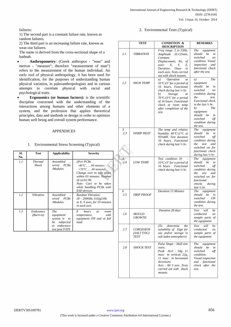
1. Environmental Stress Screening (Typical)
2. Environmental Tests (Typical)
TEST CONDITION &
DESCRIPTION
REMARKS
2.1
VIBRATION
Freq range: 5 to 33Hz,
Amplitude 0.125mm, Constant
Displacement, No. of
axes: X, Y, Z, Duration: 1hour in
each axis, Tests carried
out with shock mounts.
The equipment
should be in switched on
condition. Visual
inspection and functional check
after the test.
2.2
HIGH TEMP
a) Operation at
50C3 for a period of
16 hours. Functional
check during last ½ hr. b) Storage at
70C3C for a period
of 16 hours. Functional check at room temp
after completion of the
test.
a) The equipment
should be in
switched on condition during
the test.
Functional check in the last ½ hr.
b) The
equipment should be in
switched off
condition during the test.
3
2.3
DAMP HEAT
The temp and relative
humidity 40C2C at 95%RH. Test duration
16 hours. Functional
check during last ½ hr.
The equipment
should be in switched off
condition during
the test and switched on for
functional check
during last ½ hr.
4 2.4
LOW TEMP
Test condition H: -
10C3 for a period of
16 hours. Functional
check during last ½ hr.
The equipment should be in
switched off
condition during the test and
switched on. for
functional checks during
last ½ hr.
6
2.5
DRIP PROOF
Duration 15 Minutes The equipment
should be in switched ON
condition during the test.
2.6
MOULD
GROWTH
Duration 28 days Test will be
conducted on
sample parts of the equipment
2.7
COROSSION (SALT FOG)
TEST
(To determine the
suitability of Eqpt for use and/or storage in
salt laden atmosphere)
Test will be
conducted on sample parts of
the equipment
2.8
SHOCK TEST
Pulse Shape : Half sine
wave.
Peak Accl : 50g, 11 msec in vertical, 22g,
11 msec in horizontal
directions Axis : All 3 axis ,Tests
carried out with shock
mounts.
The equipment
should be in
switched off condition.
Visual inspection
and functional check after the
test.
Sl.
No.
Test Applicability Severity
1.1 Thermal
Shock
Assembled ,
wired PCBs /Modules
i)For PCBs
-40C……60 minutes
+70C…...60 minutes
Change over to take place
within 03 minutes. Number of cycles 06.
Note: Care to be taken
while handling PCBs with ESD devices.
1.2 Vibration Assembled ,
wired PCBs
/Modules
Random Vibration:
20 – 2000Hz, 0.02g2/Hz
in X, Y axes, for 10 minutes in each axis
1.3 Endurance (Burn-in)
The equipment/
system is to
be subjected
to endurance
test post FATS
8 hours at room temperature, with
equipment ON and at full
load.
International Journal of Engineering Research & Technology (IJERT)
IJERT
IJERT
ISSN: 2278-0181
www.ijert.orgIJERTV3IS100781
(This work is licensed under a Creative Commons Attribution 4.0 International License.)
Vol. 3 Issue 10, October- 2014
856

3. EMI/EMC TESTS AS PER MIL STD 461 D/E (Typical)
-END-
International Journal of Engineering Research & Technology (IJERT)
IJERT
IJERT
ISSN: 2278-0181
www.ijert.orgIJERTV3IS100781
(This work is licensed under a Creative Commons Attribution 4.0 International License.)
Vol. 3 Issue 10, October- 2014
857