
The product overview provides fast selection of...
76
20 The product overview provides fast selection of individual product groups within the product range. For example, the appropriate dimensions of an enclosure or the correct cooling output of a climate control component are easily located. R Courtesy of Steven Engineering, Inc.-230 Ryan Way, South San Francisco, CA 94080-6370-Main Office: (650) 588-9200-Outside Local Area: (800) 258-9200-www.stevenengineering.com
Transcript of The product overview provides fast selection of...

20
The product overview provides fast selection of individual product groups
within the product range.
For example, the appropriate dimensions of an enclosure or the correct
cooling output of a climate control component are easily located.
R
Courtesy of Steven Engineering, Inc.-230 Ryan Way, South San Francisco, CA 94080-6370-Main Office: (650) 588-9200-Outside Local Area: (800) 258-9200-www.stevenengineering.com
21Rittal Handbook 31
A
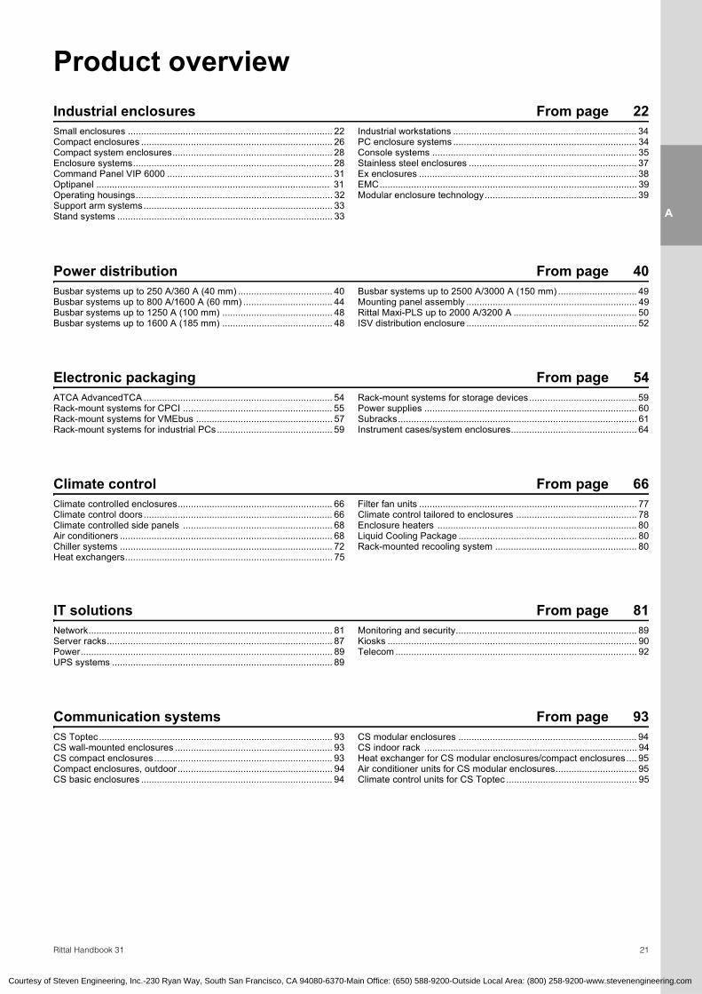
Product overviewIndustrial enclosures From page 22Small enclosures .............................................................................. 22Compact enclosures ......................................................................... 26Compact system enclosures............................................................. 28Enclosure systems............................................................................ 28Command Panel VIP 6000 ............................................................... 31Optipanel ......................................................................................... 31Operating housings........................................................................... 32Support arm systems........................................................................ 33Stand systems .................................................................................. 33
Industrial workstations ...................................................................... 34PC enclosure systems ...................................................................... 34Console systems .............................................................................. 35Stainless steel enclosures ................................................................ 37Ex enclosures ................................................................................... 38EMC.................................................................................................. 39Modular enclosure technology.......................................................... 39
Power distribution From page 40Busbar systems up to 250 A/360 A (40 mm) .................................... 40Busbar systems up to 800 A/1600 A (60 mm) .................................. 44Busbar systems up to 1250 A (100 mm) .......................................... 48Busbar systems up to 1600 A (185 mm) .......................................... 48
Busbar systems up to 2500 A/3000 A (150 mm) .............................. 49Mounting panel assembly ................................................................. 49Rittal Maxi-PLS up to 2000 A/3200 A ............................................... 50ISV distribution enclosure ................................................................. 52
Electronic packaging From page 54ATCA AdvancedTCA ........................................................................ 54Rack-mount systems for CPCI ......................................................... 55Rack-mount systems for VMEbus .................................................... 57Rack-mount systems for industrial PCs............................................ 59
Rack-mount systems for storage devices......................................... 59Power supplies ................................................................................. 60Subracks........................................................................................... 61Instrument cases/system enclosures................................................ 64
From page 66Climate controlled enclosures........................................................... 66Climate control doors........................................................................ 66Climate controlled side panels ......................................................... 68Air conditioners ................................................................................. 68Chiller systems ................................................................................. 72Heat exchangers............................................................................... 75
Filter fan units ................................................................................... 77Climate control tailored to enclosures .............................................. 78Enclosure heaters ............................................................................ 80Liquid Cooling Package .................................................................... 80Rack-mounted recooling system ...................................................... 80
IT solutions From page 81Network............................................................................................. 81Server racks...................................................................................... 87Power................................................................................................ 89UPS systems .................................................................................... 89
Monitoring and security..................................................................... 89Kiosks ............................................................................................... 90Telecom ............................................................................................ 92
Communication systems From page 93CS Toptec......................................................................................... 93CS wall-mounted enclosures ............................................................ 93CS compact enclosures.................................................................... 93Compact enclosures, outdoor........................................................... 94CS basic enclosures ......................................................................... 94
CS modular enclosures .................................................................... 94CS indoor rack ................................................................................. 94Heat exchanger for CS modular enclosures/compact enclosures.... 95Air conditioner units for CS modular enclosures............................... 95Climate control units for CS Toptec .................................................. 95
Climate control
Courtesy of Steven Engineering, Inc.-230 Ryan Way, South San Francisco, CA 94080-6370-Main Office: (650) 588-9200-Outside Local Area: (800) 258-9200-www.stevenengineering.com

Industrial Enclosures
22 Rittal Handbook 31/Enclosure Systems
A
1.
Indu
stria
l Enc
losu
res
Industrial enclosures –Experience the benefits of the comprehensive Rittal enclosure range: Perfect, cost-effective solutions for virtually any application. Rittal’s enclosures are available in a wide range of sizes and materials. In addition, our enclosures are compatible with all other Rittal products to suit specific application requirements. Rittal offers a wide range of system accessories such as climate control and power distribution to complete your enclosure package. All of your enclosure needs from a single source, that is the Rittal difference.
Complete solutions: ● Small enclosures● Compact enclosures● Compact system enclosures● Large enclosures● Industrial workstations● PC enclosure systems● Console systems
Detailed information can be found on HB 31 pages96 – 295 and on our website: www.rittal-corp.com.
Courtesy of Steven Engineering, Inc.-230 Ryan Way, South San Francisco, CA 94080-6370-Main Office: (650) 588-9200-Outside Local Area: (800) 258-9200-www.stevenengineering.com
1.1 Polycarbonate enclosures PKDimensions
mm (inches) Part No. PKPage
Height Width DepthCover
Solid Transp.
52 (2.0) 50 (2.0) 35 (1.4) 9530.0001) – 100
65 (2.6) 50 (2.0) 35 (1.4) 9531.0001) – 100
65 (2.6) 65 (2.6) 57 (2.2) 9500.000 – 100
65 (2.6) 65 (2.6) 81 (3.2) 9501.000 – 100
65 (2.6) 94 (3.7) 57 (2.2) 9502.000 – 100
65 (2.6) 94 (3.7) 81 (3.2) 9503.000 – 100
94 (3.7) 94 (3.7) 57 (2.2) 9504.000 9504.100 100
94 (3.7) 94 (3.7) 81 (3.2) 9505.000 – 100
94 (3.7) 130 (5.1) 57 (2.2) 9508.000 9508.100 100
94 (3.7) 130 (5.1) 81 (3.2) 9509.000 9509.100 100
110 (4.3) 110 (4.3) 66 (2.6) 9506.000 9506.100 100
110 (4.3) 110 (4.3) 90 (3.5) 9507.000 9507.100 100
130 (5.1) 130 (5.1) 75 (3.0) 9510.000 9510.100 100
130 (5.1) 130 (5.1) 99 (3.9) 9511.000 9511.100 100
94 (3.7) 180 (7.1) 57 (2.2) 9512.000 9512.100 100
94 (3.7) 180 (7.1) 81 (3.2) 9513.000 9513.100 100
110 (4.3) 180 (7.1) 90 (3.5) 9514.000 9514.100 101
110 (4.3) 180 (7.1) 111 (4.4) 9515.000 9515.100 101
110 (4.3) 180 (7.1) 165 (6.5) 9516.000 9516.100 101
180 (7.1) 182 (7.2) 90 (3.5) 9517.000 9517.100 101
180 (7.1) 182 (7.2) 111 (4.4) 9518.000 9518.100 101
180 (7.1) 182 (7.2) 165 (6.5) 9519.000 9519.100 101
180 (7.1) 254 (10.0) 90 (3.5) 92.00.000 9520.100 101
180 (7.1) 254 (10.0) 111 (4.4) 9521.000 9521.100 101
180 (7.1) 254 (10.0) 165 (6.5) 9522.000 9522.100 101
254 (10.0)360 (14.2) 111 (4.4) 9523.000 9523.100 101
254 (10.0)360 (14.2) 165 (6.5) 9524.000 9524.100 101
Dimensions mm (inches) Part No. PK
PageHeight Width Depth
Cover
Solid Transp.
1) With cable gland
Approvals: ● Bureau Veritas
1.1 Cast aluminum enclosures GADimensions
mm (inches) Part No. GA PageHeight Width Depth
45 (1.8) 50 (2.0) 30 (1.2) 9100.210 104
64 (2.5) 58 (2.3) 36 (1.4) 9101.210 104
64 (2.5) 98 (3.9) 36 (1.4) 9102.210 104
64 (2.5) 150 (5.9) 36 (1.4) 9103.210 104
80 (3.1) 75 (3.0) 57 (2.2) 9104.210 104
80 (3.1) 125 (4.9) 57 (2.2) 9105.210 104
80 (3.1) 175 (6.9) 57 (2.2) 9106.210 104
80 (3.1) 250 (9.8) 57 (2.2) 9107.210 104
120 (4.7) 122 (4.8) 80 (3.1) 9108.210 104
120 (4.7) 220 (8.7) 90 (3.5) 9110.210 104
122 (4.8) 360 (14.2) 80 (3.1) 9111.210 104
160 (6.3) 160 (6.3) 90 (3.5) 9112.210 104
160 (6.3) 260 (10.2) 90 (3.5) 9113.210 104
160 (6.3) 360 (14.2) 90 (3.5) 9114.210 104
230 (9.1) 200 (7.9) 110 (4.3) 9116.210 104
230 (9.1) 280 (11.0) 110 (4.3) 9117.210 104
230 (9.1) 330 (13.0) 110 (4.3) 9118.210 104
230 (9.1) 330 (13.0) 180 (7.1) 9119.210 104
Dimensions mm (inches) Part No. GA Page
Height Width Depth

Industrial Enclosures
23Rittal Handbook 31/Enclosure Systems
A
1.
Indu
stria
l Enc
losu
res
1.1 Terminal boxes KL
Approvals: ● UL● CSA● TÜV● Germanischer Lloyd● Norske Veritas● Russian Maritime Register of Shipping● Lloyds Register of Shipping● Bureau Veritas● VDE
Dimensions mm (inches) Part No. KL Part No. KL
Height Width DepthSheet steel Stainless steel
With gland plate Page Without
gland plate Page Without gland plate Page
150 (5.9) 150 (5.9) 80 (3.1) – 1514.510 107 1521.010 270
150 (5.9) 150 (5.9) 120 (4.7) – 1500.510 108 – 150 (5.9) 200 (7.9) 80 (3.1) – 1528.510 107 – 150 (5.9) 200 (7.9) 120 (4.7) – 1529.510 108 – 150 (5.9) 300 (11.8) 80 (3.1) – 1515.510 107 1522.010 270
150 (5.9) 300 (11.8) 120 (4.7) 1530.510 109 1501.510 108 – 150 (5.9) 400 (15.7) 120 (4.7) – 1589.510 108 – 200 (7.9) 200 (7.9) 80 (3.1) – 1516.510 107 1523.010 270
200 (7.9) 200 (7.9) 120 (4.7) – 1502.510 108 – 200 (7.9) 300 (11.8) 80 (3.1) – 1517.510 107 1524.010 270
200 (7.9) 300 (11.8) 120 (4.7) 1531.510 109 1503.510 108 – 200 (7.9) 400 (15.7) 80 (3.1) – 1518.510 107 – 200 (7.9) 400 (15.7) 120 (4.7) 1532.510 109 1504.510 108 1525.010 270
200 (7.9) 500 (19.7) 120 (4.7) 1533.510 109 1505.510 108 – 200 (7.9) 600 (23.6) 80 (3.1) – 1519.510 107 – 200 (7.9) 600 (23.6) 120 (4.7) 1534.510 109 1506.510 108 – 200 (7.9) 800 (31.5) 120 (4.7) 1542.510 109 1527.510 108 – 300 (11.8) 300 (11.8) 120 (4.7) 1535.510 109 1507.510 108 1526.010 270
300 (11.8) 400 (15.7) 120 (4.7) 1536.510 109 1508.510 108 – 300 (11.8) 500 (19.7) 120 (4.7) 1537.510 109 1509.510 108 – 300 (11.8) 600 (23.6) 120 (4.7) 1538.510 109 1510.510 108 – 400 (15.7) 400 (15.7) 120 (4.7) 1539.510 109 1511.510 108 – 400 (15.7) 600 (23.6) 120 (4.7) 1540.510 109 1512.510 108 – 400 (15.7) 800 (31.5) 120 (4.7) 1541.510 109 1513.510 108 –
Courtesy of Steven Engineering, Inc.-230 Ryan Way, South San Francisco, CA 94080-6370-Main Office: (650) 588-9200-Outside Local Area: (800) 258-9200-www.stevenengineering.com
1.1 E-Box EBDimensions
mm (inches) Part No. EB PageHeight Width Depth
150 (5.9) 150 (5.9) 80 (3.1) 1551.500 110
150 (5.9) 150 (5.9) 120 (4.7) 1553.500 110
200 (7.9) 200 (7.9) 80 (3.1) 1546.500 110
200 (7.9) 200 (7.9) 120 (4.7) 1549.500 110
300 (11.8) 150 (5.9) 80 (3.1) 1545.500 110
300 (11.8) 150 (5.9) 120 (4.7) 1548.500 110
300 (11.8) 200 (7.9) 80 (3.1) 1552.500 110
300 (11.8) 200 (7.9) 120 (4.7) 1554.500 110
300 (11.8) 300 (11.8) 120 (4.7) 1555.500 110
400 (15.7) 200 (7.9) 80 (3.1) 1547.500 110
400 (15.7) 200 (7.9) 120 (4.7) 1550.500 110
400 (15.7) 300 (11.8) 120 (4.7) 1556.500 110
Dimensions mm (inches) Part No. EB Page
Height Width Depth
400 (15.7) 300 (11.8) 155 (6.1) 1577.500 110
500 (19.7) 200 (7.9) 120 (4.7) 1557.500 110
600 (23.6) 300 (11.8) 155 (6.1) 1578.500 110
800 (31.5) 300 (11.8) 155 (6.1) 1579.500 110 Approvals: ● UL● CSA● TÜV● Germanischer Lloyd● Norske Veritas● Russian Maritime Register of Shipping● Lloyds Register of Shipping● Bureau Veritas● VDE
For additional sizes and part numbers, please refer to the back of the catalog.

Industrial Enclosures
24 Rittal Handbook 31/Enclosure Systems
A
1.
Indu
stria
l Enc
losu
res
1.1 Bus enclosures BG
Approvals: ● TÜV● Lloyds Register of Shipping● VDE● UL● C-UL
Dimensions in mm (inches)
PG K.O version. Metric K.O.version
Number of PG holes Part No.
BG PageNumber
of metric holes Part No. EB Page
Height Width Depth 9 11 13.5 16 21 M12 M20 M25
300 (11.8) 200 (7.9) 80 (3.1) 1 8 – 1 1 1583.510 111 9 – 2 1583.520 111
300 (11.8) 300 (11.8) 80 (3.1) 1 14 – 1 1 1584.510 111 15 – 2 1584.520 111
300 (11.8) 400 (15.7) 80 (3.1) 1 8 – 1 2 1585.510 111 19 – 3 1585.520 111
300 (11.8) 500 (19.7) 80 (3.1) 3 – 24 – – 1586.510 111 3 24 – 1586.520 111
300
B76 18
1
300
B
119
224
Approvals: ● TÜV● Lloyds Register of Shipping● VDE● UL● C-UL
Dimensions mm (inches)
PG K.O. version Metric K.O. version
Numberof PG holes Part No.
BG PageNumber
of metric holes Part No. BG Page
Height Width Depth 9 13.5 29 36 M12 M20 M32 M50
300 (11.8) 200 (7.9) 120 (4.7) 2 – 5 – 1605.510 112 2 – 5 – 1605.520 112
300 (11.8) 400 (15.7) 120 (4.7) – 2 9 1 1606.510 112 – 2 9 1 1606.520 112
300
B
135
Approvals: ● TÜV● Lloyds Register of Shipping● VDE● UL● C-UL
200
B
100
Dimensions mm (inches) Part No. BG Page
Height Width Depth
200 (7.9) 400 (15.7) 125 (4.9) 1558.510 112
200 (7.9) 600 (23.6) 125 (4.9) 1559.510 112
Courtesy of Steven Engineering, Inc.-230 Ryan Way, South San Francisco, CA 94080-6370-Main Office: (650) 588-9200-Outside Local Area: (800) 258-9200-www.stevenengineering.com

Industrial Enclosures
25Rittal Handbook 31/Enclosure Systems
A
1.
Indu
stria
l Enc
losu
res
1.1 Bus enclosures BG
Approvals: ● TÜV● Lloyds Register of Shipping● VDE● UL● C-UL
Dimensionsmm (inches) Part No. EB Page
Height Width Depth
300 (11.8) 400 (15.7) 155 (6.1) 1577.500 113
300 (11.8) 600 (23.6) 155 (6.1) 1578.500 113
300 (11.8) 800 (31.5) 155 (6.1) 1579.500 113
G1
F1
HB
H2
H1
Approvals: ● TÜV● Lloyds Register of Shipping● VDE● UL● C-UL
Dimensions mm (inches) Part No. BG Page
Height Width Depth
500 (19.7) 400 (15.7) 160 (6.3) 1611.510 113
500
B
440
100
200
Approvals: ● TÜV● Lloyds Register of Shipping● VDE● UL● C-UL
Dimensions mm (inches) Part No. BG Page
Height Width Depth
300 (11.8) 500 (19.7) 120 (4.7) 1609.510 114
300
B
115
Approvals: ● TÜV● Lloyds Register of Shipping● VDE● UL● C-UL
Dimensions mm (inches) Part No. BG Page
Height Width Depth
500 (19.7) 500 (19.7) 210 (8.3) 1050.900 114
500
500
132
232
440
Courtesy of Steven Engineering, Inc.-230 Ryan Way, South San Francisco, CA 94080-6370-Main Office: (650) 588-9200-Outside Local Area: (800) 258-9200-www.stevenengineering.com

Industrial Enclosures
26 Rittal Handbook 31/Enclosure Systems
A
1.
Indu
stria
l Enc
losu
res
Compact enclosures AE, protection category IP 69KDimensions
mm (inches) Part No. AE PageHeight Width Depth
Single-door330 (13.0) 230 (9.1) 155 (6.1) 1101.010 121
400 (15.7) 400 (15.7) 250 (9.8) 1101.020 121
650 (25.6) 400 (15.7) 250 (9.8) 1101.030 121
650 (25.6) 650 (25.6) 250 (9.8) 1101.040 121
Courtesy of Steven Engineering, Inc.-230 Ryan Way, South San Francisco, CA 94080-6370-Main Office: (650) 588-9200-Outside Local Area: (800) 258-9200-www.stevenengineering.com
1.2 Compact enclosures AEDimensions mm (inches) Part No. AE
PagePart No. AE
PageHeight Width Depth Sheet steel T 304 stainless steel T 316 stainless steel
Single-door300 (11.8) 200 (7.9) 120 (4.7) 1032.500 118 – –300 (11.8) 200 (7.9) 155 (6.1) 1035.500 118 1002.600 – 273
300 (11.8) 300 (11.8) 210 (8.3) 1033.500 118 – –300 (11.8) 380 (15.0) 155 (6.1) 1030.500 118 1004.600 – 273
300 (11.8) 380 (15.0) 210 (8.3) 1031.500 118 – –380 (15.0) 300 (11.8) 210 (8.3) – 1005.600 273
380 (15.0) 380 (15.0) 210 (8.3) 1380.500 118 1006.600 – 273
380 (15.0) 600 (23.6) 210 (8.3) 1039.500 118 1009.600 – 273
380 (15.0) 600 (23.6) 350 (13.8) 1339.500 118 – –400 (15.7) 300 (11.8) 210 (8.3) 1034.500 118 1097.000 1097.100 273
500 (19.7) 400 (15.7) 210 (8.3) 1045.500 119 – –500 (19.7) 500 (19.7) 210 (8.3) 1050.500 119 1007.600 1097.120 273
500 (19.7) 500 (19.7) 300 (11.8) 1350.500 119 1013.600 – 273
600 (23.6) 380 (15.0) 210 (8.3) 1038.500 119 1008.600 – 273
600 (23.6) 380 (15.0) 350 (13.8) 1338.500 119 – –
Approvals: ● UL● CSA● TÜV● Germanischer Lloyd
600 (23.6) 600 (23.6) 210 (8.3) 1060.500 119 1010.600 1097.160 273
600 (23.6) 600 (23.6) 350 (13.8) 1360.500 119 – –700 (27.6) 500 (19.7) 250 (9.8) 1057.500 119 1097.030 1097.130 273
760 (30.0) 600 (23.6) 210 (8.3) 1076.500 119 1012.600 1097.170 273
760 (30.0) 600 (23.6) 350 (13.8) 1376.500 119 – –760 (30.0) 760 (30.0) 210 (8.3) 1077.500 119 – –760 (30.0) 760 (30.0) 300 (11.8) 1073.500 119 1014.600 1097.180 273
800 (31.5) 600 (23.6) 250 (9.8) 1058.500 119 – –1000 (39.4) 600 (23.6) 250 (9.8) 1090.500 119 1097.010 1097.110 273
1000 (39.4) 800 (31.5) 300 (11.8) 1180.500 119 1016.600 – 273
1200 (47.2) 600 (23.6) 300 (11.8) 1260.500 120 – –1200 (47.2) 800 (31.5) 300 (11.8) 1280.500 120 1017.600 – 273
Double-door760 (30.0) 1000 (39.4) 210 (8.3) 1100.500 120 – –760 (30.0) 1000 (39.4) 300 (11.8) 1130.500 120 1097.050 – 273
1000 (39.4) 1000 (39.4) 300 (11.8) 1110.500 120 1018.600 1097.190 273
1200 (47.2) 1000 (39.4) 300 (11.8) 1213.500 120 1019.600 1097.150 273
1400 (55.1) 1000 (39.4) 300 (11.8) 1114.500 120 – –
● Norske Veritas● Russian Maritime Register of Shipping● Lloyds Register of Shipping● Bureau Veritas● VDE
For additional sizes and part numbers, please refer to the back of the catalog.

Industrial Enclosures
27Rittal Handbook 31/Enclosure Systems
A
1.
Indu
stria
l Enc
losu
res
Courtesy of Steven Engineering, Inc.-230 Ryan Way, South San Francisco, CA 94080-6370-Main Office: (650) 588-9200-Outside Local Area: (800) 258-9200-www.stevenengineering.com
Approvals: ● UL ● Russian Maritime Register of Shipping
1.2 Compact enclosures AKDimensions
mm (inches) Part No. AK Page
Height Width Depth
Single-door1200 (47.2) 600 (23.6) 400 (15.7) 1646.500 122
1200 (47.2) 800 (31.5) 400 (15.7) 1648.500 122
Double-door1200 (47.2) 1000 (39.4) 400 (15.7) 1650.500 122
1200 (47.2) 1200 (47.2) 400 (15.7) 1652.500 122
1400 (55.1) 1000 (39.4) 400 (15.7) 1647.500 122
Dimensions mm (inches) Part No.
AK PageHeight Width Depth
● CSA● TÜV● Germanischer Lloyd● Norske Veritas
● Lloyds Register of Shipping● Bureau Veritas● VDE
1.2 Fiberglass enclosures KSDimensions
mm (inches)Door(s)
Part No. KSPage
Height Width DepthViewing window
Without With
300 (11.8) 200 (7.9) 150 (5.9) 1 1423.600 – 123
350 (13.8) 250 (9.8) 150 (5.9) 1 1432.600 – 123
400 (15.7) 300 (11.8) 200 (7.9) 1 1434.600 – 123
400 (15.7) 400 (15.7) 200 (7.9) 1 1444.600 1448.600 123
500 (19.7) 500 (19.7) 300 (11.8) 1 1453.600 1454.600 123
600 (23.6) 400 (15.7) 200 (7.9) 1 1446.600 1449.600 123
Approvals:
600 (23.6) 600 (23.6) 200 (7.9) 1 1466.600 1467.600 123
800 (31.5) 600 (23.6) 300 (11.8) 1 1468.600 1469.600 124
1000 (39.4) 800 (31.5) 300 (11.8) 1 1480.600 1479.600 124
1000 (39.4) 1000 (39.4) 300 (11.8) 2 1400.600 – 124
● UL (without viewing window)● CSA (without viewing window) ● TÜV● Germanischer Lloyd● Norske Veritas
● Russian Maritime Register of Shipping● Lloyds Register of Shipping● Bureau Veritas● VDE

Industrial Enclosures
28 Rittal Handbook 31/Enclosure Systems
A
1.
Indu
stria
l Enc
losu
res
Courtesy of Steven Engineering, Inc.-230 Ryan Way, South San Francisco, CA 94080-6370-Main Office: (650) 588-9200-Outside Local Area: (800) 258-9200-www.stevenengineering.com
1.3 Compact system enclosures Rittal CMDimensions
mm (inches) Part No. CM Page
Height Width Depth
Single-door800 (31.5) 600 (23.6) 400 (15.7) 5110.500 128
1000 (39.4) 600 (23.6) 400 (15.7) 5111.500 128
1000 (39.4) 800 (31.5) 300 (11.8) 5114.500 128
1000 (39.4) 800 (31.5) 400 (15.7) 5115.500 128
1200 (47.2) 600 (23.6) 300 (11.8) 5112.500 128
Double-door1000 (39.4) 1000 (39.4) 300 (11.8) 5118.500 129
1200 (47.2) 1000 (39.4) 300 (11.8) 5119.500 129
1200 (47.2) 1000 (39.4) 400 (15.7) 5120.500 129
1200 (47.2) 1200 (47.2) 400 (15.7) 5123.500 129
1400 (55.1) 1000 (39.4) 300 (11.8) 5121.500 129
Dimensions mm (inches) Part No.
CM PageHeight Width Depth
1200 (47.2) 600 (23.6) 400 (15.7) 5113.500 128
1200 (47.2) 800 (31.5) 300 (11.8) 5116.500 128
1200 (47.2) 800 (31.5) 400 (15.7) 5117.500 129
1400 (55.1) 1000 (39.4) 400 (15.7) 5122.500 129
1.3 Compact system enclosures Rittal CLDimensions
mm (inches) Part No. CL Page
Height Width Depth
Single-door1600 (63.0) 600 (23.6) 500 (19.7) 5150.500 130
1600 (63.0) 800 (31.5) 500 (19.7) 5153.500 130
1800 (70.9) 600 (23.6) 400 (15.7) 5151.500 130
1800 (70.9) 800 (31.5) 400 (15.7) 5154.500 130
1800 (70.9) 1000 (39.4) 400 (15.7) 5156.500 130
2000 (78.7) 600 (23.6) 500 (19.7) 5152.500 130
Double-door1600 (63.0) 1200 (47.2) 500 (19.7) 5158.500 131
1800 (70.9) 1000 (39.4) 400 (15.7) 5157.500 131
1800 (70.9) 1200 (47.2) 400 (15.7) 5159.500 131
2000 (78.7) 1200 (47.2) 500 (19.7) 5160.500 131
Dimensions mm (inches) Part No.
CL PageHeight Width Depth
2000 (78.7) 800 (31.5) 500 (19.7) 5155.500 130
1.4 Freestanding enclosures ES 5000
Approvals: ● UL● CSA● TÜV● Germanischer Lloyd● Norske Veritas
● Russian Maritime Register of Shipping● Lloyds Register of Shipping● Bureau Veritas● VDE
Dimensions mm (inches) Part No. ES
PagePart No. ES
PageHeight Width Depth Sheet steel T 304 stainless steel
Single-door1600 (63.0) 600 (23.6) 400 (15.7) – 5450.600 285
1600 (63.0) 600 (23.6) 500 (19.7) 5665.500 136 – 1600 (63.0) 800 (31.5) 500 (19.7) 5865.500 136 – 1800 (70.9) 600 (23.6) 400 (15.7) 5684.500 136 – 1800 (70.9) 600 (23.6) 500 (19.7) – 5451.600 285
1800 (70.9) 800 (31.5) 400 (15.7) 5884.500 136 – 1800 (70.9) 800 (31.5) 500 (19.7) – 5452.600 285
1800 (70.9) 1000 (39.4) 400 (15.7) 5084.500 136 5454.600 285
2000 (78.7) 600 (23.6) 500 (19.7) 5605.500 136 – 2000 (78.7) 800 (31.5) 500 (19.7) 5805.500 136 – 2000 (78.7) 800 (31.5) 600 (23.6) – 5453.600 285
Double-door1600 (63.0) 1200 (47.2) 500 (19.7) 5265.500 137 – 1800 (70.9) 1000 (39.4) 400 (15.7) 5080.500 136 – 1800 (70.9) 1200 (47.2) 400 (15.7) 5284.500 137 – 1800 (70.9) 1600 (63.0) 400 (15.7) 5784.500 137 – 2000 (78.7) 1200 (47.2) 500 (19.7) 5205.500 137 5455.600 285
2000 (78.7) 1800 (70.9) 500 (19.7) 5905.500 137 –
For additional sizes and part numbers, please refer to the back of the catalog.

Industrial Enclosures
29Rittal Handbook 31/Enclosure Systems
A
1.
Indu
stria
l Enc
losu
res
1.4 TS8 modular enclosure systems
Approvals: ● UL● CSA● TÜV● Russian Maritime Register of Shipping● TÜV Mark● Lloyds Register of Shipping● Bureau Veritas● VDE● Germanischer Lloyd
Dimensions mm (inches) Part No. TS
PagePart No. TS
PageHeight Width Depth Sheet steel Stainless steel
Single-door1400 (55.1) 600 (23.6) 500 (19.7) 8645.500 138 –
1400 (55.1) 800 (31.5) 500 (19.7) 8845.500 138 –
1600 (63.0) 600 (23.6) 500 (19.7) 8665.500 139 –
1600 (63.0) 800 (31.5) 500 (19.7) 8865.500 139 –
1800 (70.9) 400 (15.7) 500 (19.7) 8485.5101) 141 –
1800 (70.9) 400 (15.7) 600 (23.6) 8486.5101) 142 –
1800 (70.9) 600 (23.6) 400 (15.7) 8684.500 140 –
1800 (70.9) 600 (23.6) 500 (19.7) 8685.500 141 8457.600 284
1800 (70.9) 600 (23.6) 600 (23.6) 8686.500 142 –
1800 (70.9) 800 (31.5) 400 (15.7) 8884.500 140 8454.600 284
1800 (70.9) 800 (31.5) 500 (19.7) 8885.500 141 8455.600 284
1800 (70.9) 800 (31.5) 600 (23.6) 8886.500 142 –
1800 (70.9) 1000 (39.4) 400 (15.7) 8084.500 140 –
2000 (78.7) 400 (15.7) 500 (19.7) 8405.5101) 144 –
2000 (78.7) 400 (15.7) 600 (23.6) 8406.5101) 145 –
2000 (78.7) 600 (23.6) 400 (15.7) 8604.500 143 –
2000 (78.7) 600 (23.6) 500 (19.7) 8605.500 144 –
2000 (78.7) 600 (23.6) 600 (23.6) 8606.500 145 8452.600 284
2000 (78.7) 600 (23.6) 800 (31.5) 8608.500 146 –
2000 (78.7) 800 (31.5) 400 (15.7) 8804.500 143 –
2000 (78.7) 800 (31.5) 500 (19.7) 8805.500 144 –
2000 (78.7) 800 (31.5) 600 (23.6) 8806.500 145 8450.600 284
2000 (78.7) 800 (31.5) 800 (31.5) 8808.500 146 –
2200 (86.6) 600 (23.6) 600 (23.6) 8626.500 147 –
2200 (86.6) 800 (31.5) 600 (23.6) 8826.500 147 –
2200 (86.6) 1200 (47.2) 600 (23.6) 8226.500 147 –
Double-door1400 (55.1) 1200 (47.2) 500 (19.7) 8245.500 138 –
1600 (63.0) 1200 (47.2) 500 (19.7) 8265.500 139 –
1800 (70.9) 800 (31.5) 500 (19.7) 8880.500 141 –
1800 (70.9) 800 (31.5) 600 (23.6) 8881.500 142 –
1800 (70.9) 1000 (39.4) 400 (15.7) 8080.500 140 –
1800 (70.9) 1200 (47.2) 400 (15.7) 8284.500 140 8456.600 284
1800 (70.9) 1200 (47.2) 500 (19.7) 8285.500 141 8453.600 284
1800 (70.9) 1200 (47.2) 600 (23.6) 8286.500 142 –
2000 (78.7) 1000 (39.4) 500 (19.7) 8005.500 144 –
2000 (78.7) 1000 (39.4) 600 (23.6) 8006.500 145 –
2000 (78.7) 1200 (47.2) 400 (15.7) 8204.500 143 –
2000 (78.7) 1200 (47.2) 500 (19.7) 8205.500 144 –
2000 (78.7) 1200 (47.2) 600 (23.6) 8206.500 145 8451.600 284
2000 (78.7) 1200 (47.2) 800 (31.5) 8208.500 146 –
2200 (86.6) 1200 (47.2) 600 (23.6) 8226.500 147 – 1) Without tubular door frame, mounting panel and gland plates.
For additional sizes and part numbers, please refer to the back of the catalog.
Courtesy of Steven Engineering, Inc.-230 Ryan Way, South San Francisco, CA 94080-6370-Main Office: (650) 588-9200-Outside Local Area: (800) 258-9200-www.stevenengineering.com

Industrial Enclosures
30 Rittal Handbook 31/Enclosure Systems
A
1.
Indu
stria
l Enc
losu
res
1.4 TS8 modular enclosure systemsElectronic enclosure
Approvals: ● UL● C-UL
Dimensions mm (inches) Part No. TS8 Page
Height Width Depth Enclosure
1600 (63.0) 600 (23.6) 600 (23.6) 8410.510 148
1600 (63.0) 600 (23.6) 800 (31.5) 8418.510 148
2000 (78.7) 600 (23.6) 600 (23.6) 8430.510 148
2000 (78.7) 600 (23.6) 800 (31.5) 8438.510 148
For modular front designDimensions
mm (inches) Part No. TS Page
Height Width Depth Enclosure
2000 (78.7) 600 (23.6) 600 (23.6) 8606.512 149
2000 (78.7) 800 (31.5) 600 (23.6) 8806.512 149
FMD enclosures
Approvals: ● UL● C-UL
Dimensions mm (inches) Part No. TS Page
Height Width Depth Enclosure
1800 (70.9) 800 (31.5) 400 (15.7) 8984.500 150
1800 (70.9) 800 (31.5) 500 (19.7) 8985.500 150
2000 (78.7) 800 (31.5) 500 (19.7) 8905.500 150
2000 (78.7) 800 (31.5) 600 (23.6) 8906.500 150
IP 65/NEMA 4X, NEMA 4
Approvals: ● UL● C-UL
Dimensions mm (inches) Part No. TS Page
Height Width Depth Enclosure
NEMA 4X, stainless steel1800 (70.9) 600 (23.6) 600 (23.6) 8458.640 151
1800 (70.9) 800 (31.5) 600 (23.6) 8459.640 151
2000 (78.7) 600 (23.6) 600 (23.6) 8452.640 151
2000 (78.7) 800 (31.5) 600 (23.6) 8450.640 151
NEMA 4, sheet steel1800 (70.9) 600 (23.6) 600 (23.6) 8686.540 151
1800 (70.9) 800 (31.5) 600 (23.6) 8886.540 151
2000 (78.7) 600 (23.6) 600 (23.6) 8606.540 151
2000 (78.7) 800 (31.5) 600 (23.6) 8806.540 151
For additional sizes and part numbers, please refer to the back of the catalog.
Courtesy of Steven Engineering, Inc.-230 Ryan Way, South San Francisco, CA 94080-6370-Main Office: (650) 588-9200-Outside Local Area: (800) 258-9200-www.stevenengineering.com

Industrial Enclosures
31Rittal Handbook 31/Enclosure Systems
A
1.
Indu
stria
l Enc
losu
res
1.4 TS8 modular enclosure systemsPrepared for EX pressurization
Dimensions mm (inches) Part No. TS
PagePart No. TS
PageHeight Width Depth Sheet steel Stainless steel
1400 (55.1) 600 (23.6) 500 (19.7) 8645.560 152 –
1400 (55.1) 800 (31.5) 500 (19.7) 8845.560 152 –
1600 (63.0) 600 (23.6) 500 (19.7) 8665.560 152 –
1600 (63.0) 800 (31.5) 500 (19.7) 8865.560 152 –
1800 (70.9) 600 (23.6) 400 (15.7) 8684.560 152 –
1800 (70.9) 600 (23.6) 500 (19.7) 8685.560 152 8457.660 152
1800 (70.9) 600 (23.6) 600 (23.6) 8686.560 152 8458.660 152
1800 (70.9) 800 (31.5) 400 (15.7) 8884.560 152 8454.660 152
1800 (70.9) 800 (31.5) 500 (19.7) 8885.560 152 8455.660 152
1800 (70.9) 800 (31.5) 600 (23.6) 8886.560 152 –
1800 (70.9) 1000 (39.4) 400 (15.7) 8084.560 152 8461.660 152
2000 (78.7) 600 (23.6) 400 (15.7) 8604.560 152 –
2000 (78.7) 600 (23.6) 500 (19.7) 8605.560 152 –
2000 (78.7) 600 (23.6) 600 (23.6) 8606.560 152 8452.660 152
2000 (78.7) 600 (23.6) 800 (31.5) 8608.560 152 –
2000 (78.7) 800 (31.5) 400 (15.7) 8804.560 152 –
2000 (78.7) 800 (31.5) 500 (19.7) 8805.560 152 –
2000 (78.7) 800 (31.5) 600 (23.6) 8806.560 152 8450.660 152
2000 (78.7) 800 (31.5) 800 (31.5) 8808.560 152 8460.660 152
2200 (86.6) 600 (23.6) 600 (23.6) 8626.560 152 –
2200 (86.6) 800 (31.5) 600 (23.6) 8826.560 152 –
1.5 VIP 6000Selection of operator/keyboard housings see pages 154 – 169.
Approvals: ● UL● CSA● TÜV● DNV● Lloyds Register of Shipping● BV● VDE
1.5 OptipanelSelection of operator/keyboard housings see pages 170 – 177.
Courtesy of Steven Engineering, Inc.-230 Ryan Way, South San Francisco, CA 94080-6370-Main Office: (650) 588-9200-Outside Local Area: (800) 258-9200-www.stevenengineering.com

Industrial Enclosures
32 Rittal Handbook 31/Enclosure Systems
A
1.
Indu
stria
l Enc
losu
res
1.5 OptipanelStandard sizes
To fit front panels
mm (inches)
To fit TFT monitor
Part No. SM
Dimensions mm (inches)
Part No. CP Page
Rear panel, hingedSupport arm con-nectionHeight Width Depth
Quick-release
fastener for screwdriver
Cam with double-bit
insert
270 x 234(10.6 x 9.2) – 278 (10.9) 314 (12.4) 60 (2.3) 6380.100 178 – � CP-S
VESA 75
483 x 310(19.0 x 12.2) – 354 (13.9) 527 (20.7) 110 (4.3) 6380.000 178 – � CP-L1)
430 x 343(16.9 x 13.5) 6450.010/.030 387 (15.2) 475 (18.7) 60 (2.3) 6380.010 178 � – CP-L1),
rear
430 x 343(16.9 x 13.5) 6450.010/.030 387 (15.2) 475 (18.7) 110 (4.3) 6380.020 178 – � CP-L1)
483 x 355(19.0 x 14.0) 6450.020/.040 399 (15.7) 527 (20.7) 60 (2.3) 6380.030 178 � – CP-L1),
rear
483 x 355(19.0 x 14.0) 6450.020/.040 399 (15.7) 527 (20.7) 110 (4.3) 6380.040 178 – � CP-L1)
1) 120 x 65 mm (4.7 x 2.6″)
1.5 Compact PanelDimensions
mm (inches) To fit Part No. CP
PageHeight Width Depth
Front panel width
mm (inches)
Front panel height
mm (inches)
Withsupport arm connection
CP-S
Withsupport arm connection
CP-L1)
Withoutsupport arm connection
238 (9.4) 241 (9.5) 87 (3.4) 178 (37.0) 200 (7.9) 6340.000 6340.010 6340.020 183
238 (9.4) 315 (12.4) 87 (3.4) 252 (9.9) 200 (7.9) 6340.300 6340.310 6340.320 183
388 (15.3) 241 (9.5) 87 (3.4) 178 (37.0) 350 (13.8) 6340.100 6340.110 6340.120 183
388 (15.3) 315 (12.4) 87 (3.4) 252 (9.9) 350 (13.8) 6340.400 6340.410 6340.420 183
521 (20.5) 241 (9.5) 87 (3.4) 178 (37.0)/4U 483 (19.0) 6340.200 6340.210 6340.220 183 1) 120 x 65 mm (4.7 x 2.6″)
1.5 Command panel enclosure with front doorBased on AE
Approvals: ● UL● C-UL
Dimensions mm (inches) Part No. CP
PagePart No. CP
PageHeight Width Depth Sheet steel Stainless steel
200 (7.9) 300 (11.8) 180 (7.1) 6534.000 184 –
300 (11.8) 300 (11.8) 150 (5.9) – 6535.010 276
300 (11.8) 300 (11.8) 180 (7.1) 6535.000 184 –
300 (11.8) 400 (15.7) 150 (5.9) – 6536.010 276
300 (11.8) 400 (15.7) 180 (7.1) 6536.000 184 –
400 (15.7) 300 (11.8) 180 (7.1) 6537.000 184 –
400 (15.7) 400 (15.7) 150 (5.9) – 6538.010 276
400 (15.7) 400 (15.7) 180 (7.1) 6538.000 184 –
400 (15.7) 600 (23.6) 150 (5.9) – 6539.010 276
500 (19.7) 500 (19.7) 180 (7.1) 6544.000 184 –
Courtesy of Steven Engineering, Inc.-230 Ryan Way, South San Francisco, CA 94080-6370-Main Office: (650) 588-9200-Outside Local Area: (800) 258-9200-www.stevenengineering.com

Industrial Enclosures
33Rittal Handbook 31/Enclosure Systems
A
1.
Indu
stria
l Enc
losu
res
1.5 Operator enclosure with rear doorBased on AE
Approvals: ● UL● C-UL
Dimensions mm (inches) Part No. CP Page
Height Width Depth
200 (7.9) 300 (11.8) 155 (6.1) 6540.200 185
300 (11.8) 380 (15.0) 210 (8.3) 6531.200 185
380 (15.0) 380 (15.0) 210 (8.3) 6530.200 185
380 (15.0) 600 (23.6) 210 (8.3) 6533.200 185
500 (19.7) 500 (19.7) 210 (8.3) 6532.200 185
1.5 Operator housingBased on AE with display panel front
Operator housing based on AE with wide VIP 6000 frame see page 187.
Approvals: ● UL● C-UL
Dimensions mm (inches) Part No. CP Page
Height Width Depth
380 (15.0) 380 (15.0) 249 (9.8) 6442.500 186
500 (19.7) 500 (19.7) 249 (9.8) 6552.500 186
600 (23.6) 380 (15.0) 249 (9.8) 6462.500 186
600 (23.6) 600 (23.6) 249 (9.8) 6662.500 186
1.5 Support arm systemsFast selection of CP-S see page 191.
Fast selection of CP-L see page 200.
Fast selection of CP-XL see page 218.
Support arm system CP-S, stainless steel see page 277.
1.5 Pedestal systemsSelection see from page 228.
Courtesy of Steven Engineering, Inc.-230 Ryan Way, South San Francisco, CA 94080-6370-Main Office: (650) 588-9200-Outside Local Area: (800) 258-9200-www.stevenengineering.com

Industrial Enclosures
34 Rittal Handbook 31/Enclosure Systems
A
1.
Indu
stria
l Enc
losu
res
1.5 Industrial workstationsFast selection see page 240.
Approvals, may be found on our website: www.rittal-corp.com
1.5 PC enclosure systems
Approvals: ● UL● CSA● TÜV● Germanischer Lloyd● Russian Maritime Register of Shipping● Lloyds Register of Shipping● VDE
Dimensions mm (inches)
Part No. PC Page Part No.
PC Page Part No. PC Page Part No.
PC Page Part No. PC Page
Height Width Depth
With keyboard drawer,
viewing door,top
With keyboard drawer,
viewing door, top, mounting compartment,
small
Withkeyboard drawer,
mountingcompartment,
large
With folding
keyboard, viewing door,
top
Withdesk section, viewing door,
top
Based on TS8 modular enclosure1600 (63.0) 600 (23.6) 636 (25.0) 8366.000 257 8366.300 257 8366.400 257 8366.100 258 8366.200 258
1600 (63.0) 600 (23.6) 836 (32.9) 8368.000 257 – – 8368.100 258 –
Based on ES1600 (63.0) 600 (23.6) 650 (25.6) 4603.703 259 4603.913 259 4603.603 259 4603.920 260 4603.704 260
1600 (63.0) 600 (23.6) 850 (33.5) 4609.703 259 – – 4609.920 260 –
Stainless steel1600 (63.0) 600 (23.6) 620 (24.4) 4650.000 283 – – – 4650.704 283
For additional sizes and part numbers, please refer to the back of the catalog.
Courtesy of Steven Engineering, Inc.-230 Ryan Way, South San Francisco, CA 94080-6370-Main Office: (650) 588-9200-Outside Local Area: (800) 258-9200-www.stevenengineering.com

Industrial Enclosures
35Rittal Handbook 31/Enclosure Systems
A
1.
Indu
stria
l Enc
losu
res
1.5 Console systems APCombination options of the modules,see page 262.
Approvals: ● UL● CSA● TÜV● Germanischer Lloyd● Russian Maritime Register of Shipping● Lloyds Register of Shipping● VDE
1.5 Top consolesDimensions
mm (inches) Part No. AP PageHeight Width Depth
Cover, front430 (16.9) 800 (31.5) 400 (15.7) 2612.500 264
430 (16.9) 1200 (47.2) 400 (15.7) 2642.500 264
430 (16.9) 1600 (63.0) 400 (15.7) 2652.500 264
Cover, front and rear430 (16.9) 800 (31.5) 500 (19.7) 2614.500 264
430 (16.9) 1200 (47.2) 500 (19.7) 2644.500 264
430 (16.9) 1600 (63.0) 500 (19.7) 2654.500 264
630 (24.8) 800 (31.5) 500 (19.7) 2647.500 264
630 (24.8) 1200 (47.2) 500 (19.7) 2648.500 264
630 (24.8) 1600 (63.0) 500 (19.7) 2649.500 264
1.5 Desk unitsDimensions
mm (inches) Part No. AP Page
Height Width Depth
For depth 400 mm (15.7″) (consoles) 200 (7.9) 800 (31.5) 850 (33.5) 2611.500 264
200 (7.9) 1200 (47.2) 850 (33.5) 2641.500 264
200 (7.9) 1600 (63.0) 850 (33.5) 2651.500 264
Dimensions mm (inches) Part No.
AP PageHeight Width Depth
For depth 500 mm (19.7″) (consoles) 200 (7.9) 800 (31.5) 950 (37.4) 2613.500 264
200 (7.9) 1200 (47.2) 950 (37.4) 2643.500 264
200 (7.9) 1600 (63.0) 950 (37.4) 2653.500 264
1.5 Bottom consolesDimensions
mm (inches) Part No. AP Page
Height Width Depth
Door(s) front670 (26.4) 800 (31.5) 400 (15.7) 2600.500 265
670 (26.4) 1200 (47.2) 400 (15.7) 2620.500 265
670 (26.4) 1600 (63.0) 400 (15.7) 2630.500 265
Dimensions mm (inches) Part No.
AP PageHeight Width Depth
Door(s) front and rear670 (26.4) 800 (31.5) 500 (19.7) 2610.500 265
670 (26.4) 1200 (47.2) 500 (19.7) 2640.500 265
670 (26.4) 1600 (63.0) 500 (19.7) 2650.500 265
1.5 Cover panelFor console, desk unit and pedestal
To fitPart No. AP PageWidth
mm (inches)Depth
mm (inches)
800 (31.5) 400 (15.7) 2615.500 265
800 (31.5) 500 (19.7) 2616.500 265
1200 (47.2) 400 (15.7) 2645.500 265
1200 (47.2) 500 (19.7) 2646.500 265
1600 (63.0) 400 (15.7) 2655.500 265
1600 (63.0) 500 (19.7) 2656.500 265
Courtesy of Steven Engineering, Inc.-230 Ryan Way, South San Francisco, CA 94080-6370-Main Office: (650) 588-9200-Outside Local Area: (800) 258-9200-www.stevenengineering.com

Industrial Enclosures
36 Rittal Handbook 31/Enclosure Systems
A
1.
Indu
stria
l Enc
losu
res
1.5 One-piece consoles AP
Approvals: ● UL● CSA● TÜV● Germanischer Lloyd● Russian Maritime Register of Shipping● Lloyds Register of Shipping● VDE
Dimensions mm (inches) Part No. AP
PagePart No. AP
PageHeight Width Depth Sheet steel Stainless steel
Single-door960 (37.8) 600 (23.6) 400 (15.7)/480 (18.9) 2666.500 266 2683.600 282
960 (37.8) 800 (31.5) 400 (15.7)/480 (18.9) 2668.500 266 2684.600 282
Double-door960 (37.8) 1000 (39.4) 400 (15.7)/480 (18.9) 2670.500 266 2685.600 282
960 (37.8) 1200 (47.2) 400 (15.7)/480 (18.9) 2672.500 266 2686.600 282
1.5 Universal consoles AP
Approvals: ● UL● CSA● TÜV● Germanischer Lloyd● Russian Maritime Register of Shipping● Lloyds Register of Shipping● VDE
Dimensions mm (inches) Part No. AP Page
Height Width Depth
With short front door1300 (51.2) 600 (23.6) 500 (19.7) 2694.500 267
With tall front door1300 (51.2) 600 (23.6) 500 (19.7) 2695.500 267
Courtesy of Steven Engineering, Inc.-230 Ryan Way, South San Francisco, CA 94080-6370-Main Office: (650) 588-9200-Outside Local Area: (800) 258-9200-www.stevenengineering.com

Industrial Enclosures
37Rittal Handbook 31/Enclosure Systems
A
1.
Indu
stria
l Enc
losu
res
1.6 Stainless steelTerminal boxes KL see page 23
Compact enclosures AE see page 26
Command panel housing with door see page 32
Support arm system CP-S see page 277
Pedestal systems see page 281
One-piece consoles AP see page 36
PC enclosure systems see page 34
TS8 modular enclosure systems see page 29
Freestanding enclosures ES 5000 see page 28
1.6 Premium Line KL, protection category IP 69K, stainless steelDimensions
mm (inches) Part No. KL PageHeight Width Depth
150 (5.9) 150 (5.9) 80 (3.1) 1024.010 271
150 (5.9) 150 (5.9) 120 (4.7) 1024.020 271
200 (7.9) 300 (11.8) 120 (4.7) 1024.030 271
300 (11.8) 400 (15.7) 120 (4.7) 1024.040 271
1.6 Bus enclosures BG, stainless steelDimensions
mm (inches) Part No. BG PageHeight Width Depth
200 (7.9) 400 (15.7) 123 (4.8) 1558.010 272
200 (7.9) 600 (23.6) 123 (4.8) 1559.010 272
300 (11.8) 200 (7.9) 80 (3.1) 1583.010 272
300 (11.8) 300 (11.8) 80 (3.1) 1584.010 272
300 (11.8) 400 (15.7) 80 (3.1) 1585.010 272
Approvals: ● TÜV● Lloyds Register of Shipping● VDE
● UL● C-UL
1.6 Premium Panel, protection category IP 69K, stainless steelDimensions mm (inches or U)
Support arm
connection
Part No. CP Page
Height Width Depth For installation panel H x W Installation depth:
Operator housing
Key-board
housing
Operator housing
Operator housing
Keyboard housing
Operator housing
Keyboard housing
With keyboard housing
460 (18.1) 200 (7.9) 530 (20.8) 120 (4.7)
483 (19) x355(8U)
483 (19) x177 (4U)
115 (4.5) front 58 (2.3)rear 63 (2.5) top 6680.000 274
460 (18.1) 200 (7.9) 530 (20.8) 120 (4.7) 115 (4.5) front 58 (2.3)rear 63 (2.5) bottom 6680.010 274
460 (18.1) 200 (7.9) 530 (20.8) 220 (8.7) 215 (8.5) front 58 (2.3)rear 63 (2.5) top 6680.100 274
460 (18.1) 200 (7.9) 530 (20.8) 220 (8.7) 215 (8.5) front 58 (2.3)rear 63 (2.5) bottom 6680.110 274
Without keyboard housing
360 (14.2) – 530 (20.8) 120 (4.7) 483 (19) x310 (7U)
–115 (4.5) – top, or
bottom by rotating the enclosure
6681.000 274
360 (14.2) – 530 (20.8) 220 (8.7) 215 (8.5) – 6681.100 274
Courtesy of Steven Engineering, Inc.-230 Ryan Way, South San Francisco, CA 94080-6370-Main Office: (650) 588-9200-Outside Local Area: (800) 258-9200-www.stevenengineering.com

Industrial Enclosures
38 Rittal Handbook 31/Enclosure Systems
A
1.
Indu
stria
l Enc
losu
res
1.6 Operator housings, stainless steel
Approvals: ● CSA● UL● C-UL
Dimensions mm (inches) Part No. CP Page
Height Width Depth
240 (9.4) 320 (12.6) 160 (6.3) 6670.000 275
320 (12.6) 400 (15.7) 160 (6.3) 6672.000 275
1.7 Ex enclosures, stainless steelWith screw fastened lid
With hinged door
Approvals: ● PTB
Dimensions mm (inches) Part No. KEL Page
Height Width Depth
150 (5.9) 150 (5.9) 80 (3.2) 9301.000 287
150 (5.9) 300 (11.8) 80 (3.2) 9302.000 287
200 (7.9) 200 (7.9) 80 (3.2) 9303.000 287
200 (7.9) 300 (11.8) 80 (3.2) 9304.000 287
200 (7.9) 400 (15.7) 120 (4.7) 9305.000 287
300 (11.8) 300 (11.8) 120 (4.7) 9306.000 287
Dimensions mm (inches) Number of
fasteners Part No. KEL PageHeight Width Depth
300 (11.8) 200 (7.9) 155 (6.1) 1 9401.600 287
300 (11.8) 380 (15.0) 155 (6.1) 1 9402.600 287
380 (15.0) 300 (11.8) 210 (8.3) 1 9409.600 287
380 (15.0) 380 (15.0) 210 (8.3) 1 9403.600 287
600 (23.6) 380 (15.0) 210 (8.3) 2 9404.600 287
600 (23.6) 600 (23.6) 210 (8.3) 2 9405.600 287
760 (30.0) 600 (23.6) 210 (8.3) 2 9406.600 287
760 (30.0) 760 (30.0) 300 (11.8) 2 9407.600 287
1000 (39.4) 800 (31.5) 300 (11.8) 2 9408.600 287
1.7 Ex enclosures, fiberglass
Approvals: ● PTB
Dimensions mm (inches) Part No. KEL Page
Height Width Depth
300 (11.8) 200 (7.9) 150 (5.9) 9201.600 288
350 (13.8) 250 (9.8) 150 (5.9) 9202.600 288
400 (15.7) 300 (11.8) 200 (7.9) 9203.600 288
400 (15.7) 400 (15.7) 200 (7.9) 9204.600 288
600 (23.6) 400 (15.7) 200 (7.9) 9205.600 288
500 (19.7) 500 (19.7) 300 (11.8) 9207.600 288
600 (23.6) 600 (23.6) 200 (7.9) 9206.600 288
800 (31.5) 600 (23.6) 300 (11.8) 9208.600 288
1000 (39.4) 800 (31.5) 300 (11.8) 9209.600 288
Courtesy of Steven Engineering, Inc.-230 Ryan Way, South San Francisco, CA 94080-6370-Main Office: (650) 588-9200-Outside Local Area: (800) 258-9200-www.stevenengineering.com

Industrial Enclosures
39Rittal Handbook 31/Enclosure Systems
A
1.
Indu
stria
l Enc
losu
res
1.8 EMC enclosuresEMC TS8 modular enclosure systems see page 291
EMC E-Box EB see page 290
EMC freestanding enclosures ES 5000 see page 291
1.8 EMC terminal boxes KLDimensions
mm (inches) Part No. KL PageHeight Width Depth
300 (11.8) 300 (11.8) 120 (4.7) 1507.710 290
Approvals: ● UL● CSA● TÜV
● Norske Veritas● Lloyds Register of Shipping● VDE
1.8 EMC compact enclosures AE
Approvals: ● UL● CSA● TÜV● Norske Veritas● Lloyds Register of Shipping● VDE
Dimensions mm (inches) Part No. AE Page
Height Width Depth
380 (15.0) 380 (15.0) 210 (8.3) 1380.700 290
380 (15.0) 600 (23.6) 210 (8.3) 1039.700 290
600 (23.6) 600 (23.6) 210 (8.3) 1060.700 290
1000 (39.4) 800 (31.5) 300 (11.8) 1180.700 290
1.9 Modular enclosure technologyCompact enclosures AE (mounting panel with modular system holes) see page 295
Approvals: ● UL● CSA● TÜV● Germanischer Lloyd● Norske Veritas
● Russian Maritime Register of Shipping● Lloyds Register of Shipping● Bureau Veritas● VDE
1.9 Modular enclosure technologyTS8 modular enclosure systems (mounting panel with modular system holes)see page 295
Approvals: ● UL● CSA● TÜV● Russian Maritime Register of Shipping● TÜV Mark
● Lloyds Register of Shipping● Bureau Veritas● VDE● Germanischer Lloyd
Courtesy of Steven Engineering, Inc.-230 Ryan Way, South San Francisco, CA 94080-6370-Main Office: (650) 588-9200-Outside Local Area: (800) 258-9200-www.stevenengineering.com

Power Distribution
40 Rittal Handbook 31/Power Distribution Systems
A
2.
Pow
er D
istr
ibut
ion
Power distribution Modern power distribution systems are becoming more powerful. Therefore, users demand the security of internationally recognized and approved power distribution components. Rittal provides switchgear designers with innovative systems that conform to the relevant regulations. Type testing to short-circuit resistance, which is performed in accredited laboratories, provides proof that Rittal busbar systems exceed industry expectations.
Successful solutions forindustrial power distribution: ● SV busbar systems● SV connection systems● SV bus-mounting fuse bases● NH bus-mounting on load isolators● NH fused isolators● SV component adaptors● SV-TS8 and Maxi-PLS● ISV distribution enclosures
Detailed information can be found on Handbook 31 pages 298 – 421 or refer to our website: www.rittal-corp.com.The current status of approvals can be found on our website: www.rittal-corp.com.
2.1 Busbar systems up to 250 A (40 mm)Rittal Mini-PLS
Description Length mm PU Part No. SV Page
Mini-PLS busbar supports up to 250 A, 690 V~, 3-pole, 40 mm bar center distance – 4 9600.000 302
Mini-PLS end cover – 2 9610.000 302
Mini-PLS special busbarsE-Cu 250 A, 120 mm2
500 3 9601.000 302
700 3 9602.000 302
1100 3 9603.000 302
1500 3 9624.000 302
Mini-PLS busbar connectors – 3 9611.000 302
Mini-PLS base tray sections
250 1 9604.000 302
500 1 9605.000 302
700 1 9606.000 302
1100 1 9607.000 302
Mini-PLS cover sections250 1 9608.000 302
500 1 9609.000 302
Mini-PLS busbar connection adaptorVersion PU Part No. SV Page
63 A, 690 V~, connection top/bottom for round conductors AWG 16 – 2 and for laminated copper bars,clamping area 10 x 8 mm
1 9613.000 303
250 A, 690 V~, connection top/bottom for round conductors AWG/mcm 8 – 250 and for laminated copper bars,clamping area 17 x 15 mm
1 9612.000 303
Courtesy of Steven Engineering, Inc.-230 Ryan Way, South San Francisco, CA 94080-6370-Main Office: (650) 588-9200-Outside Local Area: (800) 258-9200-www.stevenengineering.com

Power Distribution
41Rittal Handbook 31/Power Distribution Systems
A
2.
Pow
er D
istr
ibut
ion
2.1 Busbar systems up to 250 A (40 mm)Mini-PLS component adaptorCable outlet at the top
Note:For allocation of power circuit-breakers/starter combinations,see pages 1128/1129.
Construction width mm
Rated current up to Voltage Connection
cables1)
Support railsPU Part No.
SV PageHeight mm Number
45 12 A 690 V~ AWG 14 7.5 1 1 9614.110 304
45 25 A 690 V~ AWG 12 7.5 1 1 9614.100 304
45 25 A 690 V~ AWG 12 15 1 1 9615.100 304
54 25 A 690 V~ AWG 12 7.5 1 1 9614.000 304
54 25 A 690 V~ AWG 12 15 1 1 9615.000 304
72 25 A 690 V~ AWG 12 7.5 1 1 9625.000 304
72 25 A 690 V~ AWG 12 15 1 1 9626.000 304
90 25 A 690 V~ AWG 12 7.5 1 1 9629.010 304
99 25 A 690 V~ AWG 12 15 1 1 9629.020 304
108 25 A 690 V~ AWG 12 7.5 1 1 9629.030 304
54 40 A 690 V~ AWG 10 7.5 1 1 9616.000 306
54 40 A 690 V~ AWG 10 15 1 1 9617.000 306
72 40 A 690 V~ AWG 10 7.5 1 1 9627.000 306
72 40 A 690 V~ AWG 10 15 1 1 9628.000 306
90 100 A 690 V~ AWG 2 Mounting panel 1 9629.000 306 1) AWG = American Wire Gauges
AWG 14 = 2.08 mm2 2.5 mm2
AWG 12 = 3.31 mm2 4 mm2
AWG 10 = 5.26 mm2 6 mm2
Mini-PLS quick-fit component adaptor
Note:For allocation of power circuit-breakers/starter combinations,see page 1128.
Construction width mm
Rated currentup to1) Voltage For power circuit-breakers PU Part No.
SV Page
54 25 A (32 A) 690 V~ AEG, General Electric, Schiele 1 9618.000 305
54 25 A (32 A) 690 V~ Moeller Electric 1 9619.000 305
54 25 A (32 A) 690 V~ Allen Bradley, Moeller 1 9620.000 305
54 25 A (32 A) 690 V~ Telemecanique 1 9621.000 305
54 25 A (32 A) 690 V~ ABB, Siemens, Telemecanique 1 9622.000 305 1) Rated current 25 A at 35°C (95°F) and 32 A at 25°C (77°F) ambient temperature
Mini-PLS bus-mounting fuse base
NH on-load isolators
Version PU Part No. SV Page
D 02-E 18, 63 A, 400 V~, terminal for round conductors AWG 16 – 6 1 9630.000 307
Version PU Part No. SV Page
Size 000, 100 A, 690 V~, cable outlet top/bottom,terminal up to AWG 1 1 3431.000 307
Mini-PLS busbar adaptorfor SV 3431.000 1 9629.100 307
Courtesy of Steven Engineering, Inc.-230 Ryan Way, South San Francisco, CA 94080-6370-Main Office: (650) 588-9200-Outside Local Area: (800) 258-9200-www.stevenengineering.com

Power Distribution
42 Rittal Handbook 31/Power Distribution Systems
A
2.
Pow
er D
istr
ibut
ion
2.1 Busbar systems up to 360 A (40 mm)System components
Description Dimensions mm
Length mm PU Part No. SV Page
Busbar support up to 360 A, 690 V~, 3-pole, 40 mm bar center distance,for E-Cu busbars 12 x 5 mm to 15 x 10 mm
– – 4 9350.000 308
End cover – – 2 9610.000 308
BusbarsE-Cu
12 x 5 2400 6 3580.000 308
12 x 10 2400 6 3580.100 308
15 x 5 2400 6 3581.000 308
15 x 10 2400 6 3581.100 308
Base tray sections
– 250 1 9604.000 309
– 500 1 9605.000 309
– 700 1 9606.000 309
– 1100 1 9607.000 309
Cover sections– 250 1 9608.000 309
– 500 1 9609.000 309
Busbar cover sectionsfor busbars
12/15 x 5 mm – 1000 4 9350.010 309
12/15 x 10 mm – 1000 4 9350.060 309
Busbar connectors – – 3 9350.070 309
Busbar connection adaptor
Version For busbars mm PU Part No. SV Page
360 A, 690 V AC, for round conductors AWG/mcm 8 – 250 (max. 250 A) and laminated copper bars (max. 360 A), clamping area17 x 15 mm
12 x 5/10 1 9350.020 310
15 x 5/10 1 9350.030 310
Bus-mounting fuse base
NH on-load isolators
Version For busbars mm PU Part No. SV Page
D 02-E 18, 63 A, 400 V~, terminal for round conductors AWG 16 – 6
12 x 5/10 1 9350.050 311
15 x 5/10 1 9350.500 311
Version For busbars mm PU Part No. SV Page
Size 000, 100 A, 690 V~,cable outlet top/bottom,terminal up to AWG 1
– 1 3431.000 311
Busbar adaptorfor SV 3431.000
12 x 5/10 1 9350.400 311
15 x 5/10 1 9350.410 311
Courtesy of Steven Engineering, Inc.-230 Ryan Way, South San Francisco, CA 94080-6370-Main Office: (650) 588-9200-Outside Local Area: (800) 258-9200-www.stevenengineering.com

Power Distribution
43Rittal Handbook 31/Power Distribution Systems
A
2.
Pow
er D
istr
ibut
ion
2.1 Busbar systems up to 360 A (40 mm)Multi-functional component adaptor
Note:For allocation of power circuit-breakers/starter combinations,see pages 1129/1130.
Con-struc-tion
width mm
Ratedcurrent up to
Voltage Connection cables1)
Connection of round
conductors up to
Cableoutlet
Support rails Forbar
thickness mm
PU Part No. SV PageHeight
mm Number
45 12 A 690 V~ AWG 14 – top 10 1 5 1 9350.080 312
45 12 A 690 V~ AWG 14 – top 10 1 10 1 9350.090 312
45 25 A 690 V~ AWG 12 – top 10 1 5 1 9350.100 312
45 25 A 690 V~ AWG 12 – top 10 1 10 1 9350.110 312
45 25 A 690 V~ AWG 12 – top 10 2 5 1 9350.120 312
45 25 A 690 V~ AWG 12 – top 10 2 10 1 9350.130 312
45 25 A 690 V~ AWG 12 – top 10 2 5 1 9350.260 312
45 25 A 690 V~ AWG 12 – top 10 2 10 1 9350.270 312
45 25 A 690 V~ AWG 12 – top 10 2 (1 var.) 5 1 9350.140 312
45 25 A 690 V~ AWG 12 – top 10 2 (1 var.) 10 1 9350.150 312
90 25 A 690 V~ AWG 12 – top 10 1 5 1 9350.280 313
90 25 A 690 V~ AWG 12 – top 10 1 10 1 9350.290 313
99 25 A 690 V~ AWG 12 – top 10 2 5 1 9350.300 313
99 25 A 690 V~ AWG 12 – top 10 2 10 1 9350.310 313
108 25 A 690 V~ AWG 12 – top 10 2 5 1 9350.320 313
108 25 A 690 V~ AWG 12 – top 10 2 10 1 9350.330 313
45 25 A 690 V~ – AWG 6 top 10 2 (1 var.) 5 1 9350.160 314
45 25 A 690 V~ – AWG 6 top 10 2 (1 var.) 10 1 9350.170 314
45 25 A 690 V~ – AWG 6 top/bottom 10 2 5 1 9350.180 314
45 25 A 690 V~ – AWG 6 top/bottom 10 2 10 1 9350.190 314
54 40 A 690 V~ – AWG 6 top 10 2 5 1 9350.220 314
54 40 A 690 V~ – AWG 6 top 10 2 10 1 9350.230 314
54 40 A 690 V~ – AWG 6 top/bottom 10 2 5 1 9350.240 314
54 40 A 690 V~ – AWG 6 top/bottom 10 2 10 1 9350.250 314
54 40 A 690 V~ AWG 10 – top 10 2 5 1 9350.200 315
54 40 A 690 V~ AWG 10 – top 10 2 10 1 9350.210 315
54 40 A 690 V~ AWG 10 – top 15 1 5 1 9350.340 315
54 40 A 690 V~ AWG 10 – top 15 1 10 1 9350.350 315 1) AWG = American Wire Gauges
AWG 14 = 2.08 mm2 2.5 mm2
AWG 12 = 3.31 mm2 4 mm2
AWG 10 = 5.26 mm2 6 mm2
Component adaptor
Note:For allocation of power circuit-breakers/starter combinations,see page 1130.
Version For busbars mm PU Part No. SV Page
100 A, 690 V~, construction width 90 mm, connection cables AWG 2, cable outlet at the top
12 x 5/10 1 9350.420 315
15 x 5/10 1 9350.430 315
Courtesy of Steven Engineering, Inc.-230 Ryan Way, South San Francisco, CA 94080-6370-Main Office: (650) 588-9200-Outside Local Area: (800) 258-9200-www.stevenengineering.com
Power Distribution
44 Rittal Handbook 31/Power Distribution Systems
A
2.
Pow
er D
istr
ibut
ion
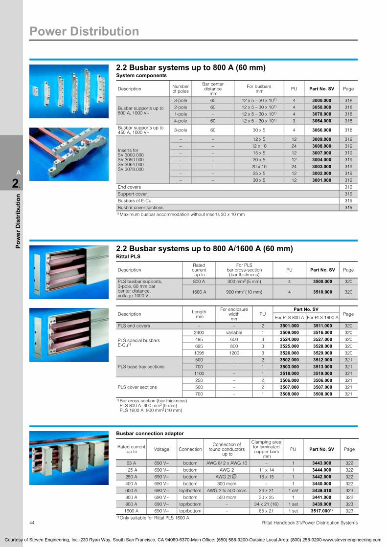
2.2 Busbar systems up to 800 A (60 mm)System components
Description Numberof poles
Bar center distance
mm
For busbars mm PU Part No. SV Page
Busbar supports up to 800 A, 1000 V~
3-pole 60 12 x 5 – 30 x 101) 4 3000.000 318
2-pole 60 12 x 5 – 30 x 101) 4 3050.000 318
1-pole – 12 x 5 – 30 x 101) 4 3078.000 318
4-pole 60 12 x 5 – 30 x 101) 3 3064.000 318
Busbar supports up to 450 A, 1000 V~ 3-pole 60 30 x 5 4 3066.000 318
Inserts forSV 3000.000SV 3050.000SV 3064.000SV 3078.000
– – 12 x 5 12 3009.000 319
– – 12 x 10 24 3008.000 319
– – 15 x 5 12 3007.000 319
– – 20 x 5 12 3004.000 319
– – 20 x 10 24 3003.000 319
– – 25 x 5 12 3002.000 319
– – 30 x 5 12 3001.000 319
End covers 319
Support cover 319
Busbars of E-Cu 319
Busbar cover sections 319 1) Maximum busbar accommodation without inserts 30 x 10 mm
2.2 Busbar systems up to 800 A/1600 A (60 mm)Rittal PLS
DescriptionRatedcurrent up to
For PLSbar cross-section(bar thickness)
PU Part No. SV Page
PLS busbar supports,3-pole, 60 mm barcenter distance, voltage 1000 V~
800 A 300 mm2 (5 mm) 4 3500.000 320
1600 A 900 mm2 (10 mm) 4 3510.000 320
Description Length mm
For enclosure width mm
PUPart No. SV
PageFor PLS 800 A For PLS 1600 A
PLS end covers – – 2 3501.000 3511.000 320
PLS special busbarsE-Cu1)
2400 variable 1 3509.000 3516.000 320
495 600 3 3524.000 3527.000 320
695 800 3 3525.000 3528.000 320
1095 1200 3 3526.000 3529.000 320
PLS base tray sections
500 – 2 3502.000 3512.000 321
700 – 1 3503.000 3513.000 321
1100 – 1 3518.000 3519.000 321
PLS cover sections
250 – 2 3506.000 3506.000 321
500 – 2 3507.000 3507.000 321
700 – 1 3508.000 3508.000 321 1) Bar cross-section (bar thickness)
PLS 800 A: 300 mm2 (5 mm) PLS 1600 A: 900 mm2 (10 mm)
Busbar connection adaptor
Rated current up to Voltage Connection
Connection ofround conductors
up to
Clamping areafor laminated copper bars
mm
PU Part No. SV Page
63 A 690 V~ bottom AWG 8/ 2 x AWG 10 – 1 3443.000 322
125 A 690 V~ bottom AWG 2 11 x 14 1 3444.000 322
250 A 690 V~ bottom AWG 2/ 16 x 15 1 3442.000 322
400 A 690 V~ bottom 300 mcm – 1 3440.000 322
600 A 690 V~ top/bottom AWG 2 to 500 mcm 24 x 21 1 set 3439.010 323
800 A 690 V~ bottom 500 mcm 30 x 25 1 3441.000 322
800 A 690 V~ top/bottom – 34 x 21 (16) 1 set 3439.000 323
1600 A 690 V~ top/bottom – 65 x 21 1 set 3517.0001) 323 1) Only suitable for Rittal PLS 1600 A
∅
Courtesy of Steven Engineering, Inc.-230 Ryan Way, South San Francisco, CA 94080-6370-Main Office: (650) 588-9200-Outside Local Area: (800) 258-9200-www.stevenengineering.com

Power Distribution
45Rittal Handbook 31/Power Distribution Systems
A
2.
Pow
er D
istr
ibut
ion
2.2 Busbar systems up to 800 A/1600 A (60 mm)Connection clamps/system coversDescription Page
Conductor connection clamps 324
Plate clamp 324
System covers 324
Multi-functional component adaptor
Note:For allocation of power circuit-breakers/starter combinations,see pages 1130/1131.
Con-struc-tion
width mm
Ratedcurrent up to
Voltage Connection cables1)
Connection of
roundconductors
up to
Cableoutlet
Support rails For bar
thickness mm
PU Part No. SV PageHeight
mm Number
45 12 A 690 V~ AWG 14 – top 10 1 5 1 9320.160 325
45 12 A 690 V~ AWG 14 – top 10 1 10 1 9320.170 325
45 25 A 690 V~ AWG 12 – top 10 1 5 1 9320.180 325
45 25 A 690 V~ AWG 12 – top 10 1 10 1 9320.190 325
45 25 A 690 V~ AWG 12 – top 10 2 5 1 9320.200 325
45 25 A 690 V~ AWG 12 – top 10 2 10 1 9320.210 325
45 25 A 690 V~ AWG 12 – top 10 2 5 1 9320.440 325
45 25 A 690 V~ AWG 12 – top 10 2 10 1 9320.450 325
45 25 A 690 V~ AWG 12 – top 10 2 (1 var.) 5 1 9320.220 325
45 25 A 690 V~ AWG 12 – top 10 2 (1 var.) 10 1 9320.230 325
45 25 A 690 V~ AWG 12 – bottom 10 2 5 1 9320.240 325
45 25 A 690 V~ AWG 12 – bottom 10 2 10 1 9320.250 325
90 25 A 690 V~ AWG 12 – top 10 2 5 1 9320.380 326
90 25 A 690 V~ AWG 12 – top 10 2 10 1 9320.390 326
99 25 A 690 V~ AWG 12 – top 10 2 5 1 9320.400 326
99 25 A 690 V~ AWG 12 – top 10 2 10 1 9320.410 326
108 25 A 690 V~ AWG 12 – top 10 2 5 1 9320.420 326
108 25 A 690 V~ AWG 12 – top 10 2 10 1 9320.430 326
45 25 A 690 V~ – AWG 6 top 10 2 (1 var.) 5 1 9320.260 326
45 25 A 690 V~ – AWG 6 top 10 2 (1 var.) 10 1 9320.270 326
45 25 A 690 V~ – AWG 6 top/bottom 10 2 5 1 9320.280 326
45 25 A 690 V~ – AWG 6 top/bottom 10 2 10 1 9320.290 326
54 40 A 690 V~ AWG 10 – top 10 2 5 1 9320.300 327
54 40 A 690 V~ AWG 10 – top 10 2 10 1 9320.310 327
54 40 A 690 V~ AWG 10 – top 15 1 5 1 9320.460 327
54 40 A 690 V~ AWG 10 – top 15 1 10 1 9320.470 327
54 40 A 690 V~ AWG 10 – bottom 10 2 5 1 9320.320 327
54 40 A 690 V~ AWG 10 – bottom 10 2 10 1 9320.330 327
54 40 A 690 V~ – AWG 6 top 10 2 5 1 9320.340 327
54 40 A 690 V~ – AWG 6 top 10 2 10 1 9320.350 327
54 40 A 690 V~ – AWG 6 top/bottom 10 2 5 1 9320.360 327
54 40 A 690 V~ – AWG 6 top/bottom 10 2 10 1 9320.370 327 1) AWG = American Wire Gauges
AWG 14 = 2.08 mm2 2.5 mm2
AWG 12 = 3.31 mm2 4 mm2
AWG 10 = 5.26 mm2 6 mm2
Courtesy of Steven Engineering, Inc.-230 Ryan Way, South San Francisco, CA 94080-6370-Main Office: (650) 588-9200-Outside Local Area: (800) 258-9200-www.stevenengineering.com

Power Distribution
46 Rittal Handbook 31/Power Distribution Systems
A
2.
Pow
er D
istr
ibut
ion
2.2 Busbar systems up to 800 A/1600 A (60 mm)Component adaptorCable outlet at the top
Note:For allocation of power circuit-breakers/starter combinations,see page 1131.
Construction
width mm
Ratedcurrent up to
Voltage Connectioncables1)
Connection ofround
conductors
Support rails Forbar
thickness mm
PU Part No. SV PageHeight
mm Number
54 50 A 690 V~ AWG 10 (32 A) AWG 16 – 8 7.5 1 5 1 3540.000 328
54 50 A 690 V~ AWG 10 (32 A) AWG 16 – 8 7.5 1 10 1 3541.000 328
54 50 A 690 V~ AWG 10 (32 A) AWG 16 – 8 7.5 2 5 1 3040.000 328
54 50 A 690 V~ AWG 10 (32 A) AWG 16 – 8 7.5 2 10 1 3041.000 328
72 50 A 690 V~ AWG 10 (32 A) AWG 16 – 8 7.5 1 5 1 3544.000 328
72 50 A 690 V~ AWG 10 (32 A) AWG 16 – 8 7.5 1 10 1 3545.000 328
108 50 A 690 V~ AWG 10 (32 A) AWG 16 – 8 7.5 2 5 1 3042.000 329
108 50 A 690 V~ AWG 10 (32 A) AWG 16 – 8 7.5 2 10 1 3043.000 329
126 50 A 690 V~ AWG 10 (32 A) AWG 16 – 8 7.5 2 5 1 3069.000 329
126 50 A 690 V~ AWG 10 (32 A) AWG 16 – 8 7.5 2 10 1 3070.000 329
144 50 A 690 V~ AWG 10 (32 A) AWG 16 – 8 15 2 5 1 3044.000 329
144 50 A 690 V~ AWG 10 (32 A) AWG 16 – 8 15 2 10 1 3045.000 329
54 63 A 690 V~ AWG 8 AWG 16 – 8 7.5 1 5 1 3036.000 330
54 63 A 690 V~ AWG 8 AWG 16 – 8 7.5 1 10 1 3037.000 330
72 63 A 690 V~ AWG 8 AWG 16 – 8 7.5 2 5 1 3038.000 330
72 63 A 690 V~ AWG 8 AWG 16 – 8 7.5 2 10 1 3039.000 330
72 63 A 690 V~ AWG 8 AWG 16 – 8 15 1 5 1 3067.000 330
72 63 A 690 V~ AWG 8 AWG 16 – 8 15 1 10 1 3068.000 330
72 63 A 690 V~ AWG 8 AWG 16 – 8 15 2 5 1 3046.000 330
72 63 A 690 V~ AWG 8 AWG 16 – 8 15 2 10 1 3047.000 330
144 63 A 690 V~ AWG 8 AWG 16 – 8 15 2 5 1 3048.000 330
144 63 A 690 V~ AWG 8 AWG 16 – 8 15 2 10 1 3049.000 330
54 63 A 690 V~ AWG 10 AWG 16 – 8 7.5 1 5 – 10 1 3445.000 331
54 63 A 400 V~ – AWG 16 – 6 7.5 1 5 – 10 1 3446.0002) 331
90 100 A 690 V~ AWG 2 – Mounting panel 5 1 9320.000 332
90 100 A 690 V~ AWG 2 – Mounting panel 10 1 9320.010 332
110 160 A 690 V~ – AWG 10 – 2/ Mounting panel 5 – 10 1 3438.000 332
110 160 A 690 V~ – AWG 10 – 2/ Mounting panel 5 – 10 1 3539.000 332
110 250 A 690 V~ – AWG 1 – 4/ – 5 – 10 1 3437.000 333
110 250 A 690 V~ – AWG 1 – 4/ – 5 – 10 1 3437.010 333 1) AWG = American Wire Gauges
AWG 10 = 5.26 mm2 6 mm2
AWG 8 = 8.37 mm2 10 mm2
2) With pre-fuse unit D 02-E 18
∅∅∅∅
Component support (without contact system)
Construction width mm
Support rails For bar thickness
mmPU Part No. SV PageHeight
mm Number
54 7.5 1 5 1 3542.000 333
54 7.5 1 10 1 3543.000 333
72 7.5 1 5 1 3546.000 333
72 7.5 1 10 1 3547.000 333
Courtesy of Steven Engineering, Inc.-230 Ryan Way, South San Francisco, CA 94080-6370-Main Office: (650) 588-9200-Outside Local Area: (800) 258-9200-www.stevenengineering.com

Power Distribution
47Rittal Handbook 31/Power Distribution Systems
A
2.
Pow
er D
istr
ibut
ion
2.2 Busbar systems up to 800 A/1600 A (60 mm)Bus-mounting fuse bases
Type Rated current Voltage
Forbar
thickness mm
PU
Part No. SV
PageBus-mountingfuse base
Contacthazard
protectioncover
Endcaps
Sidecover
For clamping screw attachmentD 02-E 181) 63 A 400 V~ 5 – 10 10 3418.000 3419.000 3420.000 3093.000 334
D II-E 272) 25 A 500 V~ 5 – 10 10 3427.000 3428.000 3429.000 3093.000 334
D III-E 332) 63 A 690 V~ 5 – 10 10 3433.000 3434.000 3435.000 3093.000 334
For snap-on mountingD 02-E 181) 63 A 400 V~ 5 10 3422.000 3424.000 3425.000 3093.000 335
D 02-E 181) 63 A 400 V~ 10 10 3423.000 3424.000 3425.000 3093.000 335
D II-E 273) 25 A 500 V~ 5 10 3520.000 3522.000 3429.000 3093.000 335
D II-E 273) 25 A 500 V~ 10 10 3521.000 3522.000 3429.000 3093.000 335
D III-E 333) 63 A 690 V~ 5 10 3530.000 3532.000 3435.000 3093.000 335
D III-E 333) 63 A 690 V~ 10 10 3531.000 3532.000 3435.000 3093.000 335 1) Adaptor sleeve 2) Adaptor screw 3) Gauge ring
NH fused isolators/NH on-load isolators
Description Cableoutlet
Type of connection
Forbar thickness
mmPU Part No.
SV Page
NH fused isolators size 00160 A, 690 V~
top Screw M8 5 – 10 1 3591.020 336
bottom Screw M8 5 – 10 1 3591.030 336
NH on-load isolators size 000100 A, 690 V~ top/bottom Terminal
up to AWG 1 – 1 3431.000 337
Busbar adaptorfor SV 3431.000
– – 5 1 9320.040 337
– – 10 1 9320.050 337
NH bus-mounting on-load isolator
Version Cableoutlet Type of connection PU Part No.
SV
With fuse monitoringPagePart No.
SV1) Part No.
SV2) Size 00, 160 A, 690 V~ top Screw M8 up to AWG 3/ 1 3400.000 3490.000 3490.210 338
Size 00, 160 A, 690 V~ bottom Screw M8 up to AWG 3/ 1 3401.000 3491.000 3491.210 338
Size 00, 160 A, 690 V~ top Clamp-type terminal connection up to AWG 2/ 1 3402.000 3492.000 3492.210 338
Size 00, 160 A, 690 V~ bottom Clamp-type terminal connection up to AWG 2/ 1 3403.000 3493.000 3493.210 338
Size 1, 250 A, 690 V~ top Screw M10 up to 250 mcm 1 3411.000 3495.000 3495.210 339
Size 1, 250 A, 690 V~ bottom Screw M10 up to 250 mcm 1 3410.000 3494.000 3494.210 339
Size 2, 400 A, 690 V~ top Screw M10 up to 500 mcm 1 3415.020 3415.120 3415.210 340
Size 2, 400 A, 690 V~ bottom Screw M10 up to 500 mcm 1 3415.030 3415.130 3415.230 340
Size 3, 630 A, 690 V~ top Screw M10 up to 500 mcm 1 3095.020 3095.120 3095.210 341
Size 3, 630 A, 690 V~ bottom Screw M10 up to 500 mcm 1 3095.030 3095.130 3095.230 341 1) Electromechanical fuse monitoring 2) Electronic fuse monitoring and LED display
∅∅
∅
∅
Courtesy of Steven Engineering, Inc.-230 Ryan Way, South San Francisco, CA 94080-6370-Main Office: (650) 588-9200-Outside Local Area: (800) 258-9200-www.stevenengineering.com

Power Distribution
48 Rittal Handbook 31/Power Distribution Systems
A
2.
Pow
er D
istr
ibut
ion
2.3 Busbar systems up to 1250 A (100 mm)System components
Description For busbars mm PU Part No.
SV Page
Busbar supports up to 1250 A, 1000 V~,3-pole, 100 mm bar center distance – 4 3073.000 343
Insertsfor SV 3073.000
30 x 10 24 3074.000 343
40 x 10 24 3075.000 343
50 x 10 24 3076.000 343
BusbarsE-Cu 343
End cover – 10 3083.000 343
Busbar cover sections 343
Connection clamps/system coversDescription Page
Plate clamps 344
Conductor connection clamps 344
System covers 344
NH bus-mounting on-load isolator
Version Cable outlet Type of connection PU Part No.
SV
With fuse monitoringPagePart No.
SV1) Part No.
SV2) Size 00, 160 A, 690 V~ top Screw M8 up to AWG 3/ 1 3400.000 3490.000 3490.210 345
Size 00, 160 A, 690 V~ bottom Screw M8 up to AWG 3/ 1 3401.000 3491.000 3491.210 345
Size 00, 160 A, 690 V~ top Clamp-type terminal connection up to AWG 2/ 1 3402.000 3492.000 3492.210 345
Size 00, 160 A, 690 V~ bottom Clamp-type terminalconnection up to AWG 2/ 1 3403.000 3493.000 3493.210 345
Size 1, 250 A, 690 V~ top Screw M10 up to 250 mcm 1 3411.000 3495.000 3495.210 346
Size 1, 250 A, 690 V~ bottom Screw M10 up to 250 mcm 1 3410.000 3494.000 3494.210 346
Size 2, 400 A, 690 V~ top/bottom Screw M10 up to 500 mcm 1 3415.010 3415.110 3415.310 347
Size 3, 630 A, 690 V~ top/bottom Screw M10 up to 500 mcm 1 3095.010 3095.110 3095.310 348
Busbar adaptorfor NH isolators
Size 00, Size 1 1 3412.000 345
Size 2 1 3499.020 347
Size 3 1 3499.030 348 1) Electromechanical fuse monitoring 2) Electronic fuse monitoring and LED display
∅∅
∅
∅
NH fused isolator
Version Cable outlet Type of connection PU Part No. SV Page
Size 00, 160 A, 690 V~ top/bottom Screw M8 1 3591.010 349
2.4 Busbar systems up to 1600 A (185 mm)System components
Description For busbars mm PU Part No.
SV Page
Busbar supports up to 1600 A, 1000 V~,3-pole, 185 mm bar center distance 50 – 80 x 101) 2 3052.000 351
Insertsfor SV 3052.000
50 x 10 24 3074.000 351
60 x 10 24 3075.000 351
BusbarsE-Cu 351
Busbar cover sections 351 1) Maximum busbar accommodation without inserts 80 x 10 mm.
The base component of the busbar support may also be used as a single-pole support.
Courtesy of Steven Engineering, Inc.-230 Ryan Way, South San Francisco, CA 94080-6370-Main Office: (650) 588-9200-Outside Local Area: (800) 258-9200-www.stevenengineering.com

Power Distribution
49Rittal Handbook 31/Power Distribution Systems
A
2.
Pow
er D
istr
ibut
ion
2.4 Busbar systems up to 1600 A (185 mm)Connection clampsDescription Page
Plate clamps 352
Conductor connection clamps 352
NH fused isolatorsVersion Cable outlet Type of connection PU Part No. SV Page
Size 00, 160 A, 690 V~ top/bottom Screw M81 3591.0401) 353
2 3591.0502) 353
Size 1, 250 A, 690 V~ top/bottom Screw M12 1 3485.000 353
Size 2, 400 A, 690 V~ top/bottom Screw M12 1 3486.000 353
Size 3, 630 A, 690 V~ top/bottom Screw M12 1 3487.000 353 1) Including busbar adaptor 2) Including busbar adaptor (double adaptor)
2.5 Busbar systems up to 2500 A/3000 A (150 mm)System components
Description Rated current up to
Max. bar accommodation without spacing pieces PU Part No.
SV Page
Busbar support, 3-pole,150 mm bar center distance, voltage 1000 V~
2500 A 2 x 80 x 10 mm 2 3055.000 355
3000 A 2 x 100 x 10 mm 2 3057.000 355
Spacing pieces 12 3056.000 355
Busbars E-Cu 355
Connection plates 356
Bar insulation 356
2.6 Mounting panel assemblyNH on-load isolators
Version Cable outlet Type ofconnection PU Part No.
SVWith fuse monitoring
PagePart No. SV1) Part No. SV2)
Size 000,100 A, 690 V~ top/bottom Terminal
up to AWG 1 1 3431.000 – – 358
Size 00,160 A, 690 V~ top/bottom Screw M8
up to AWG 3/ 1 3488.000 – – 358
Size 00,160 A, 690 V~ bottom Screw M8
up to AWG 3/ 1 – – 3488.310 358
Size 00,160 A, 690 V~ top/bottom Clamp-type terminal
up to AWG 2/ 1 3489.000 – – 358
Size 00,160 A, 690 V~ bottom Clamp-type terminal
up to AWG 2/ 1 – – 3489.310 358
Size 1,250 A, 690 V~ top/bottom Screw M10
up to 250 mcm 1 3409.000 – – 358
Size 1,250 A, 690 V~ bottom Screw M10
up to 250 mcm 1 – – 3409.310 358
Size 2,400 A, 690 V~ top/bottom Screw M10
up to 500 mcm 1 3415.010 – – 359
Size 2,400 A, 690 V~ top/bottom Screw M10
up to 500 mcm 1 – 3415.110 – 359
Size 2,400 A, 690 V~ bottom Screw M10
up to 500 mcm 1 – – 3415.310 359
Size 3,630 A, 690 V~ top/bottom Screw M10
up to 500 mcm 1 3095.010 – – 359
Size 3,630 A, 690 V~ top/bottom Screw M10
up to 500 mcm 1 – 3095.110 – 359
Size 3,630 A, 690 V~ bottom Screw M10
up to 500 mcm 1 – – 3095.310 359
1) Electromechanical fuse monitoring 2) Electronic fuse monitoring and LED display
∅
∅
∅
∅
Courtesy of Steven Engineering, Inc.-230 Ryan Way, South San Francisco, CA 94080-6370-Main Office: (650) 588-9200-Outside Local Area: (800) 258-9200-www.stevenengineering.com

Power Distribution
50 Rittal Handbook 31/Power Distribution Systems
A
2.
Pow
er D
istr
ibut
ion
2.8 Rittal Maxi-PLS up to 2000 A/3200 ADescription Up to 2000 A
pageUp to 3200 A
page
Connection kits (3-pole) 368 – 369 378 – 381
Connection kits for coupling sets (3-pole) 370 – 371 382 – 383
Connection kits for rear section (3-pole) 372 – 373 384 – 387
Connection kits for coupling sets – rear section (3-pole) 374 – 375 388 – 389
System componentsBusbar support 376 390
Busbar support, suitable for top mounting 376 390
End supports 376 390
System attachment 376 390
Maxi-PLS busbars, E-Cu 57 376 390
Cover section 376 390
Connector sets E-Cu 376 390
End cover 376 390
Stabilizer – 390
Connection componentsConnection bracket E-Cu 377 391
Isolator chassis 377 391
U contact maker E-Cu 377 391
Connection clamp 377 391
Connection plates 377 391
Terminal studs 377 391
Sliding blocks 377 391
Sliding nuts 377 391
Threaded bolts 377 391
2.8 Rittal Maxi-PLS SV-TS8 enclosuresFor incoming/outgoing
Dimensionsmm (inches) Part No. SV Part No. TS
PageHeight Width Depth
ForMaxi-PLS
Enclosure Sidewalls PU 2
Base/plinthPU 1 set
Componentsfront and rearmm (inches)
Trim panelssides
mm (inches)
100 (3.9) 200 (7.9) 100 (3.9) 200 (7.9)
3-pole2000 (78.7) 600 (23.6) 600 (23.6) 2000 A 9660.6651) 8106.235 8601.600 8602.600 8601.060 8602.060 392
2000 (78.7) 600 (23.6) 600 (23.6) 2000 A 9660.6752) 8106.512 8601.600 8602.600 8601.060 8602.060 392
2000 (78.7) 800 (31.5) 600 (23.6) 3200 A 9660.8651) 8106.235 8601.800 8602.800 8601.060 8602.060 392
2000 (78.7) 800 (31.5) 600 (23.6) 3200 A 9660.8752) 8106.512 8601.800 8602.800 8601.060 8602.060 392
4-pole2000 (78.7) 800 (31.5) 600 (23.6) 2000 A 9649.6251) 8106.235 8601.800 8602.800 8601.060 8602.060 393
2000 (78.7) 800 (31.5) 600 (23.6) 2000 A 9649.6352) 8106.512 8601.800 8602.800 8601.060 8602.060 393
2000 (78.7) 800 (31.5) 800 (31.5) 3200 A 9659.6251) 8108.235 8601.800 8602.800 8601.080 8602.080 393
2000 (78.7) 800 (31.5) 800 (31.5) 3200 A 9659.6352) 8108.512 8601.800 8602.800 8601.080 8602.080 393 1) 1-door 2) 3-door
Courtesy of Steven Engineering, Inc.-230 Ryan Way, South San Francisco, CA 94080-6370-Main Office: (650) 588-9200-Outside Local Area: (800) 258-9200-www.stevenengineering.com

Power Distribution
51Rittal Handbook 31/Power Distribution Systems
A
2.
Pow
er D
istr
ibut
ion
2.8 Rittal Maxi-PLS SV-TS8 enclosuresFor Rittal NH fused isolators
Dimensions mm (inches) Part No. TS
PageHeight Width Depth Enclosure1) Sidewalls
PU 2
Base/plinthPU 1 set
Componentsfront and rearmm (inches)
Trim panelssides
mm (inches)
100 (3.9) 200 (7.9) 100 (3.9) 200 (7.9)
3-pole/4-pole (2000 A/3200 A) 2000 (78.7) 600 (23.6) 500 (19.7) 9660.5052) 8105.235 8601.600 8602.600 8601.050 8602.050 394
2000 (78.7) 600 (23.6) 600 (23.6) 9660.6052) 8106.235 8601.600 8602.600 8601.060 8602.060 394
2000 (78.7) 600 (23.6) 800 (31.5) 9660.8052) 8108.235 8601.600 8602.600 8601.080 8602.080 394
2000 (78.7) 800 (31.5) 500 (19.7) 9660.5352) 8105.235 8601.800 8602.800 8601.050 8602.050 394
2000 (78.7) 800 (31.5) 600 (23.6) 9660.6352) 8106.235 8601.800 8602.800 8601.060 8602.060 394
2000 (78.7) 800 (31.5) 800 (31.5) 9660.8352) 8108.235 8601.800 8602.800 8601.080 8602.080 394
2000 (78.7) 1000 (39.4) 500 (19.7) 9660.5953) 8105.235 8601.000 8602.000 8601.050 8602.050 395
2000 (78.7) 1000 (39.4) 600 (23.6) 9660.6953) 8106.235 8601.000 8602.000 8601.060 8602.060 395
2000 (78.7) 1200 (47.2) 500 (19.7) 9660.5553) 8105.235 8601.200 8602.200 8601.050 8602.050 395
2000 (78.7) 1200 (47.2) 600 (23.6) 9660.6553) 8106.235 8601.200 8602.200 8601.060 8602.060 395
2000 (78.7) 1200 (47.2) 800 (31.5) 9660.8553) 8108.235 8601.200 8602.200 8601.080 8602.080 395 1) Without mounting panel 2) Single door 3) Double door
For NH fused isolatorsDimensions
mm (inches)Part No.
SV Part No. TS
PageHeight Width Depth Enclosure
1-doorSidewalls
PU 2
Base/plinthPU 1 set
Componentsfront and rearmm (inches)
Trim panelssides
mm (inches)
100 (3.9) 200 (7.9) 100 (3.9) 200 (7.9)
3-pole (2000 A/3200 A) 2000 (78.7) 1000 (39.4) 600 (23.6) 9660.5151) 8106.512 8601.000 8602.000 8601.060 8602.060 396
2000 (78.7) 1200 (47.2) 600 (23.6) 9660.5451) 8106.512 8601.200 8602.200 8601.060 8602.060 396
2000 (78.7) 1000 (39.4) 600 (23.6) 9660.4152) 8106.512 8601.000 8602.000 8601.060 8602.060 396
2000 (78.7) 1200 (47.2) 600 (23.6) 9660.4452) 8106.512 8601.200 8602.200 8601.060 8602.060 396
4-pole (2000 A)2000 (78.7) 1000 (39.4) 600 (23.6) 9649.6651) 8106.512 8601.000 8602.000 8601.060 8602.060 397
2000 (78.7) 1200 (47.2) 600 (23.6) 9649.6751) 8106.512 8601.200 8602.200 8601.060 8602.060 397
2000 (78.7) 1000 (39.4) 600 (23.6) 9649.6452) 8106.512 8601.000 8602.000 8601.060 8602.060 397
2000 (78.7) 1200 (47.2) 600 (23.6) 9649.6552) 8106.512 8601.200 8602.200 8601.060 8602.060 397
4-pole (3200 A)2000 (78.7) 1000 (39.4) 800 (31.5) 9659.6651) 8108.512 8601.000 8602.000 8601.080 8602.080 397
2000 (78.7) 1200 (47.2) 800 (31.5) 9659.6751) 8108.512 8601.200 8602.200 8601.080 8602.080 397
2000 (78.7) 1000 (39.4) 800 (31.5) 9659.6452) 8108.512 8601.000 8602.000 8601.080 8602.080 397
2000 (78.7) 1200 (47.2) 800 (31.5) 9659.6552) 8108.512 8601.200 8602.200 8601.080 8602.080 397 1) For NH fused isolators, brand ABB SlimLine 2) For NH fused isolators, brand Jean Müller SASIL
System components for NH fused isolator panelsFor NH fused isolator brands ABB SlimLine/Jean Müller SASIL Description Page
T-bar support 800 A/1600 A 398
T-busbars E-Cu 800 A/1600 A 398
T-connector kits 800 A/1600 A 398
Courtesy of Steven Engineering, Inc.-230 Ryan Way, South San Francisco, CA 94080-6370-Main Office: (650) 588-9200-Outside Local Area: (800) 258-9200-www.stevenengineering.com

Power Distribution
52 Rittal Handbook 31/Power Distribution Systems
A
2.
Pow
er D
istr
ibut
ion
2.8 Rittal Maxi-PLS SV-TS8 enclosuresFor coupling sets
Dimensionsmm (inches) Part No. SV Part No. TS
PageHeight Width Depth
ForMaxi-PLS
Enclosure Sidewalls PU 2
Base/plinthPU 1 set
Componentsfront and rearmm (inches)
Trim panelssides
mm (inches)
100 (3.9) 200 (7.9) 100 (3.9) 200 (7.9)
3-pole2000 (78.7) 800 (31.5) 600 (23.6) 2000 A 9660.305 8106.512 8601.800 8602.800 8601.060 8602.060 399
2000 (78.7) 1000 (39.4) 600 (23.6) 3200 A 9660.355 8106.512 8601.000 8602.000 8601.060 8602.060 399
4-pole2000 (78.7) 1000 (39.4) 600 (23.6) 2000 A 9649.685 8106.512 8601.000 8602.000 8601.060 8602.060 399
2000 (78.7) 1000 (39.4) 800 (31.5) 3200 A 9659.695 8108.512 8601.000 8602.000 8601.080 8602.080 399
System components for coupling setsDescription Page
Coupling sets, vertical 400
System attachment for vertical coupling set 400
2.9 ISV distribution enclosuresISV-TS8 enclosures for distribution enclosures up to 630 A
Dimensionsmm (inches)
Part No. SV Part No. TS
PageHeight Width Depth Enclosure Sidewalls
PU 2
Base/plinthPU 1 set
Componentsfront and rearmm (inches)
Trim panelssides
mm (inches)
100 (3.9) 200 (7.9) 100 (3.9) 200 (7.9)
2000 (78.7) 600 (23.6) 400 (15.7) 9665.9451) 8104.235 8601.600 8602.600 8601.040 8602.040 409
2000 (78.7) 600 (23.6) 600 (23.6) 9665.9051) 8106.235 8601.600 8602.600 8601.060 8602.060 409
2000 (78.7) 850 (33.5) 400 (15.7) 9665.9551) 8104.235 8601.850 8602.850 8601.040 8602.040 409
2000 (78.7) 850 (33.5) 600 (23.6) 9665.9151) 8106.235 8601.850 8602.850 8601.060 8602.060 409
2000 (78.7) 1100 (43.3) 400 (15.7) 9665.9652) 8104.235 8601.300 8602.100 8601.040 8602.040 409
2000 (78.7) 1100 (43.3) 600 (23.6) 9665.9252) 8106.235 8601.300 8602.100 8601.060 8602.060 409 1) Single door 2) Double door
ISV-TS8 enclosures for distribution enclosures up to 1600 ADimensionsmm (inches)
Part No. SV Part No. TS
PageHeight Width Depth Enclosure Sidewalls
PU 2
Base/plinthPU 1 set
Componentsfront and rearmm (inches)
Trim panelssides
mm (inches)
100 (3.9) 200 (7.9) 100 (3.9) 200 (7.9)
2000 (78.7) 600 (23.6) 600 (23.6) 9665.9751) 8106.235 8601.600 8602.600 8601.060 8602.060 410
2000 (78.7) 850 (33.5) 600 (23.6) 9665.9851) 8106.235 8601.850 8602.850 8601.060 8602.060 410 1) Single door
Courtesy of Steven Engineering, Inc.-230 Ryan Way, South San Francisco, CA 94080-6370-Main Office: (650) 588-9200-Outside Local Area: (800) 258-9200-www.stevenengineering.com
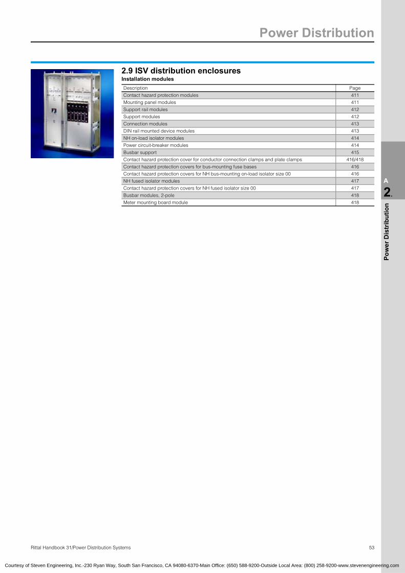
Power Distribution
53Rittal Handbook 31/Power Distribution Systems
A
2.
Pow
er D
istr
ibut
ion
2.9 ISV distribution enclosuresInstallation modules Description Page
Contact hazard protection modules 411
Mounting panel modules 411
Support rail modules 412
Support modules 412
Connection modules 413
DIN rail mounted device modules 413
NH on-load isolator modules 414
Power circuit-breaker modules 414
Busbar support 415
Contact hazard protection cover for conductor connection clamps and plate clamps 416/418
Contact hazard protection covers for bus-mounting fuse bases 416
Contact hazard protection covers for NH bus-mounting on-load isolator size 00 416
NH fused isolator modules 417
Contact hazard protection covers for NH fused isolator size 00 417
Busbar modules, 2-pole 418
Meter mounting board module 418
Courtesy of Steven Engineering, Inc.-230 Ryan Way, South San Francisco, CA 94080-6370-Main Office: (650) 588-9200-Outside Local Area: (800) 258-9200-www.stevenengineering.com

Electronic Packaging
54 Rittal Handbook 31/Electronic Systems
A
3.
Elec
tron
ic P
acka
ging
Fully assembled, pre-wired and tested. Rittal Electronic Systems offer complete know-how in the field of electronic packaging, from variable subrack systems, to a variety of enclosure solutions, operation and monitoring solutions, backplanes, power supplies, and climate control components, to complete microcomputer systems for VMEbus, CompactPCI, ATCA or ATX.
The complete range forelectronic packaging ● Microcomputer systems● Industrial PC systems● 19″ keyboard rack ● Power supplies● Backplanes● Subrack systems● System enclosures/instrument cases
A full range of accessories and detailed information can be found on Handbook 31 pages 422 – 577 or refer to our website: www.rittal-corp.com.
3.1 AdvancedTCAAdvancedTCA Shelf VA-1 (Rittal ShMC connectable from rear)
U Slots Backplane IPMI Rittal ShMC1)
Switchslots PC PEM PEM-Amp RiCool-2 Part No.
RP Page
13 14 Dual Star bussed 2 x kernels center 2 x 2 x 90 A each 4 x 48 V-IPMI 3688.306 426
13 14 Dual Star bussed 2 x kernels center 2 x 4 x 50 A each 4 x 48 V-IPMI On request 426
13 14 Full Mesh bussed 2 x kernels 1 + 2 2 x 2 x 90 A each 4 x 48 V-IPMI 3688.305 426
13 14 Full Mesh bussed 2 x kernels 1 + 2 2 x 4 x 50 A each 4 x 48 V-IPMI 3688.463 426 1) ShMC not included with the supply.
AdvancedTCA Shelf VB-1 (Intel ShMC connectable from front)
U Slots Backplane IPMI Intel ShMC1)
Switchslots PC PEM 2) PEM-Amp RiCool-2 Part No.
RP Page
13 14 Dual Star radial 2 x CMM center 2 x 2 x 90 A each 4 x 48 V-IPMI 3688.303 427
13 14 Dual Star radial 2 x CMM center 2 x 4 x 50 A each 4 x 48 V-IPMI On request 427
13 14 Full Mesh radial 2 x CMM 1 + 2 2 x 2 x 90 A each 4 x 48 V-IPMI 3688.301 427
13 14 Full Mesh radial 2 x CMM 1 + 2 2 x 4 x 50 A each 4 x 48 V-IPMI 3688.466 427 1) ShMC not included with the supply. 2) PEM-IPMI included with the supply.
AdvancedTCA Shelf version VB-2 (Pigeon Point ShMC connectable from front)
U Slots Backplane IPMI Pigeon Point ShMC1)
Switchslots PC PEM 2) PEM-Amp RiCool-2 Part No.
RP Page
13 14 Dual Star bussed 2 x CMM center 2 x 2 x 90 A each 4 x 48 V-IPMI 3688.304 427
13 14 Dual Star bussed 2 x CMM center 2 x 4 x 50 A each 4 x 48 V-IPMI 3688.469 427
13 14 Full Mesh bussed 2 x CMM 1 + 2 2 x 2 x 90 A each 4 x 48 V-IPMI 3688.302 427
13 14 Full Mesh bussed 2 x CMM 1 + 2 2 x 4 x 50 A each 4 x 48 V-IPMI 3688.470 427 1) ShMC not included with the supply. 2) PEM-IPMI included with the supply.
Courtesy of Steven Engineering, Inc.-230 Ryan Way, South San Francisco, CA 94080-6370-Main Office: (650) 588-9200-Outside Local Area: (800) 258-9200-www.stevenengineering.com

Electronic Packaging
55Rittal Handbook 31/Electronic Systems
A
3.
Elec
tron
ic P
acka
ging
3.2 CPCIRack-mount systems, Slim-Box
UDepth mm
(inches)
Installation space for Part No. RP
PageBoards mm
(inches)
Rear I/Oboards
mm (inches)
WithCPCI backplane
andpower supply
WithCPCI backplane
withoutpower supply
Withoutbackplane
with power supply
1 300 (11.8) 160 (6.3) 80 (3.1) 9907.475 3689.177 9907.479 433
1 300 (11.8) 160 (6.3) – 9907.471 – – 433
2 300 (11.8) 160 (6.3) 80 (3.1) 9907.476 3689.178 9907.480 433
2 300 (11.8) 160 (6.3) – 9907.472 – – 433
3 300 (11.8) 160 (6.3) 80 (3.1) 9907.477 3689.179 9907.481 433
3 300 (11.8) 160 (6.3) – 9907.473 – – 433
4 300 (11.8) 160 (6.3) 80 (3.1) 9907.478 3689.180 9907.482 433
4 300 (11.8) 160 (6.3) – 9907.474 – – 433
Rack-mount systems, Ripac
Slots(version) U Depth
mm (inches)
Wiring space depth
mm (inches)
For PCBU x mm (inches)
Part No. RPPage
MPS system
5 horizontal 3 405 (15.9) 210 (8.3) 6 U x 160 (6.3) 3687.717 434
7 horizontal 4 405 (15.9) 210 (8.3) 6 U x 160 (6.3) 3687.718 434
8 4 (3 + 1) 405 (15.9) 210 (8.3) 3 U/6 U x 160 (6.3) 3687.719 435
8 7 (6 + 1) 405 (15.9) 210 (8.3) 3 U/6 U x 160 (6.3) 3687.720 435
8 7 (6 + 2 x 1/2) 405 (15.9) 210 (8.3) 6 x U 160 (6.3) 3687.721 436
8 (with radial fan) 9 (6 + 2 x 11/2) 290.5(11.4) 85.5 (3.7) 6 U x 160 (6.3) 3687.723 437
3.2 CPCIBackplanes 3.5U
Slots VersionPart No. RP
Page 32-bit 64-bit
2 SBE – 3687.864 440
3 SBE 3687.865 3686.578 440
4 SBE 3687.863 3686.576 440
5 SBE 3687.862 3686.575 440
6 SBME 3687.861 3686.548 440
7 SBE 3687.860 3686.547 440
8 S 3687.859 3686.546 440
S = Stand aloneB = Beginning segment M = Middle segment E = Ending segment
Courtesy of Steven Engineering, Inc.-230 Ryan Way, South San Francisco, CA 94080-6370-Main Office: (650) 588-9200-Outside Local Area: (800) 258-9200-www.stevenengineering.com

Electronic Packaging
56 Rittal Handbook 31/Electronic Systems
A
3.
Elec
tron
ic P
acka
ging
3.2 CPCIBackplanes 6.5U
Slots VersionPart No. RP Page
32-bit 64-bit
Backplanes1) 2 SBE – 3686.581 440
3 SBE 3687.871 3686.580 440
4 SBE 3687.870 3686.579 440
5 SBE 3687.869 3686.552 440
6 SBME 3687.868 3686.551 440
7 SBE 3687.867 3686.550 440
8 S 3687.866 3686.549 440
Backplanes for low profile bridge2) 3 SBE – 3689.209 440
4 SBE – 3689.208 440
5 SBE – 3689.207 440
6 SBME – 3689.206 440
7 SBE – 3689.205 440 1) Cannot be used when rear connection of 80 mm (3.1″) boards is required. 2) May be used when rear connection of 80 mm (3.1″) boards is required.S = Stand alone B = Beginning segment M = Middle segment E = Ending segment
Backplanes 7U with H.110
Slots VersionPart No. RP Page
H.110 connected to system slot
H.110 not connected tosystem slot
3 S 3688.5081) – 441
4 SE 3688.5072) – 441
5 SB 3687.8752) 3688.5062) 441
6 SBME 3687.8742) 3688.5052) 441
7 SBE 3687.8732) 3688.5042) 441
8 S 3687.877 9805.494 441 1) Extendible with low profile bridges 2) Extendible with bridges RP 3686.571S = Stand alone B = Beginning segment M = Middle segment E = Ending segment
Backplanes 7U, Switch Fabric to PICMG 2.16 Width Number of slots Description of slots Part No. RP Page
32 HP 81 fabric slot6 node slots with CPCI and H.1101 host slot
3689.188 442
32 HP 8 see RP 3689.188, but without H.110 3686.414 442
84 HP 16
1 fabric slot6 node slots with CPCI and H.1101 host slot1 fabric slot6 node slots with CPCI and H.1101 host slot3 slots for power supplies
3686.396 442
84 HP 16 see RP 3686.396, but without H.110 3689.186 442
84 HP 21
7 node slots with CPCI and H.1101 host slot1 node slot with H.110, without CPCI1 fabric slot7 node slots with CPCI and H.1101 host slot1 node slot with H.110, without CPCI1 fabric slot1 alarm slot
3686.397 442
84 HP 21 see RP 3686.397, but without H.110 3689.190 442
84 HP 21 see RP 3686.397, but without CPCI 3689.191 442
Courtesy of Steven Engineering, Inc.-230 Ryan Way, South San Francisco, CA 94080-6370-Main Office: (650) 588-9200-Outside Local Area: (800) 258-9200-www.stevenengineering.com

Electronic Packaging
57Rittal Handbook 31/Electronic Systems
A
3.
Elec
tron
ic P
acka
ging
3.2 CPCIModular CPCI bridgeDescription Part No. RP Page
64-bit CPCI bridge 3686.571 443
Modular low profile bridgeVersion Bits Part No. RP Page
left-right 32 3689.210 443
right-left 32 3689.211 443
left-right 64 9810.637 443
right-left 64 9812.625 443
Only suitable for use in conjunction with low profile backplanes.
Power supply board Description Part No. RP Page
3.5U, 16 HPBoard for pluggable power supplywith Positronic connector, 47 pin 3688.603 444
ATX (12″) cable harness 9810.337 444
ATX (16″) cable harness 3686.570 444
ATX (20″) cable harness 9810.338 444
6.5U, 8 HP1) Board for pluggable power supplywith Positronic connector, 47 pin 3688.607 445
ATX (12″) cable harness 9810.337 445
ATX (16″) cable harness 3686.570 445
ATX (20″) cable harness 9810.338 445
6.5U, 16 HP1) Board for 2 x pluggable power supplies with Positronic connector, 47 pin 3688.608 446
ATX (12″) cable harness 9810.337 446
ATX (16″) cable harness 3686.570 446
ATX (20″) cable harness 9810.338 446 1) Extended delivery times.
3.2 VMERack-mount systems, Slim-Box
U Depth mm (inches)
Installation space for Part No. RP
PageBoards mm (inches)
Rear I/O boards mm (inches)
WithVME backplane
andpower supply
Withoutbackplane
with power supply
1 300 (11.8) 160 (6.3) 80 (3.1) – 9907.479 447
1 360 (14.2) 160 (6.3) 160 (6.3) 9907.467 – 447
1 300 (11.8) 160 (6.3) – 9907.463 – 447
2 300 (11.8) 160 (6.3) 80 (3.1) – 9907.480 447
2 360 (14.2) 160 (6.3) 160 (6.3) 9907.468 – 447
2 300 (11.8) 160 (6.3) – 9907.464 – 447
3 300 (11.8) 160 (6.3) 80 (3.1) – 9907.481 447
3 360 (14.2) 160 (6.3) 160 (6.3) 9907.469 – 447
3 300 (11.8) 160 (6.3) – 9907.465 – 447
4 300 (11.8) 160 (6.3) 80 (3.1) – 9907.482 447
4 360 (14.2) 160 (6.3) 160 (6.3) 9907.470 – 447
4 300 (11.8) 160 (6.3) – 9907.466 – 447
Courtesy of Steven Engineering, Inc.-230 Ryan Way, South San Francisco, CA 94080-6370-Main Office: (650) 588-9200-Outside Local Area: (800) 258-9200-www.stevenengineering.com

Electronic Packaging
58 Rittal Handbook 31/Electronic Systems
A
3.
Elec
tron
ic P
acka
ging
3.2 VME/VME64xRack-mount systems, Ripac
Slots(version) U For Depth
mm (inches)
Wiring space depth mm (inches)
ForPCB
U x mm (inches)
Part No. RPPage
MPS system
5 horizontal 3 VME 405 (15.9) 210 (8.3) 6U x 160 (6.3) 3687.698 448
5 horizontal 3 VME64x 405 (15.9) 210 (8.3) 6U x 160 (6.3) 3687.699 448
7 horizontal 4 VME 405 (15.9) 210 (8.3) 6U x 160 (6.3) 3687.700 448
7 horizontal 4 VME64x 405 (15.9) 210 (8.3) 6U x 160 (6.3) 3687.696 448
12 4 (3 + 1) VME 405 (15.9) 210 (8.3) 3U x 160 (6.3) 3687.702 449
12 7 (6 + 1) VME 405 (15.9) 210 (8.3) 3/6U x 160 (6.3) 3687.703 449
12 7 (6 + 1) VME64x 405 (15.9) 210 (8.3) 3/6U x 160 (6.3) 3687.704 449
12 7 (6 + 2 x 1/2) VME 405 (15.9) 210 (8.3) 6U x 160 (6.3) 3687.705 450
12 7 (6 + 2 x 1/2) VME64x 405 (15.9) 210 (8.3) 6U x 160 (6.3) 3687.706 450
12 (with radial fan) 9 (6 + 2 x 11/2) VME64x 290.5 (11.4) 85.5 (3.4) 6U x 160 (6.3) 3687.708 451
Courtesy of Steven Engineering, Inc.-230 Ryan Way, South San Francisco, CA 94080-6370-Main Office: (650) 588-9200-Outside Local Area: (800) 258-9200-www.stevenengineering.com
3.2 VMEBackplanes VME64x
Slots
Dimensions in mm (inches) Part No. RP
PageHeight Width Without P0
connectorWith P0
connector
6U5
261.6(10.3)
100 (3.9) 3687.608 3687.609 454
7 161.5 (6.4) 3687.610 3687.611 454
9 181.5 (7.1) 9904.930 9904.932 454
10 202 (8.0) 9904.931 9904.933 454
12 242.5 (9.5) 3686.634 3686.473 454
21 242.5 (9.5) 3686.635 3686.474 454
6.5U5
283.7(11.2)
100 (3.9) 9910.012 9910.007 454
7 161.5 (6.4) 9910.013 9910.008 454
9 181.5 (7.1) 9910.014 9910.009 454
10 202 (8.0) 9904.928 9904.929 454
12 242.5 (9.5) 9910.015 9910.010 454
21 425.5 (16.8) 9910.016 9910.011 454
Slots
Dimensions in mm (inches) Part No. RP
PageHeight Width Without P0
connectorWith P0
connector
Backplanes VME J1/J2 Monolithic
SlotsDimensions in mm (inches) Part No. RP
PageHeight Width Passive Active
2
261.7 (10.3)
39.5 (1.6) 3686.475 3686.495 455
3 59.5 (2.3) 3686.476 3686.496 455
4 80 (3.1) 3686.477 3686.497 455
5 100 (3.9) 3686.478 3686.498 455
6 120.5 (4.7) 3686.479 3686.499 455
7 141 (5.6) 3686.480 3686.500 455
8 161.5 (6.4) 3686.481 3686.501 455
9 181.5 (7.1) 3686.482 3686.502 455
10 202 (8.0) 3686.483 3686.503 455
11 222.5 (8.8) 3686.484 3686.504 455
12
261.7 (10.3)
242.5 (9.5) 3686.485 3686.505 455
13 263 (10.4) 3686.486 3686.506 455
14 283 (11.1) 3686.487 3686.507 455
15 303.5 (11.9) 3686.488 3686.508 455
16 324 (12.8) 3686.489 3686.509 455
17 344 (13.5) 3686.490 3686.510 455
18 364.5 (14.4) 3686.491 3686.511 455
19 385 (15.2) 3686.492 3686.512 455
20 405 (15.9) 3686.493 3686.513 455
21 425.5 (16.8) 3686.494 3686.514 455
SlotsDimensions in mm (inches) Part No. RP
PageHeight Width Passive Active
Backplanes VME J1 system bus
SlotsDimensions in mm (inches) Part No. RP Page
Height Width
3
128.4(5.1)
59.5 (2.4) 3686.555 456
4 80 (3.1) 3686.556 456
5 100 (3.9) 3686.557 456
6 120.5 (4.7) 3686.558 456
7 141 (5.6) 3686.559 456
8 161.5 (6.4) 3686.560 456
9 181.5 (7.1) 3686.561 456
10 202 (8.0) 3686.562 456
12
128.4(5.1)
242.5 (9.5) 3686.563 456
13 263 (10.4) 3686.564 456
14 283 (11.4) 3686.565 456
15 303.5 (11.9) 3686.566 456
18 364.5 (14.4) 3686.567 456
20 405 (16.0) 3686.568 456
21 425.5 (16.8) 3686.569 456
SlotsDimensions in mm (inches) Part No. RP Page
Height Width

Electronic Packaging
59Rittal Handbook 31/Electronic Systems
A
3.
Elec
tron
ic P
acka
ging
3.3 Rack-mount systems for industrial PCs
U
Dimensions in mm (inches)
PU Part No. RP PageHeightFlanges/Sidewalls
Width Depth
ATX Ripac 4U, aluminium4 177 (7.0) 19″ 440 (17.3) 1 3659.000 462
ATX 1, 2 and 4U, sheet steel1 44 (1U) 19″ 532.5/530 (21/20.9) 1 3659.500 463
2 88 (3.5) 19″ 532.5/530 (21/20.9) 1 3659.600 464
4 177/174 (7.0/6.9) 19″ 442.5/440 (17.5/17.3) 1 3659.900 465
ATX Economy with front door 4U, sheet steel4 177/174 (7.0/6.9) 19″ 430/415 (16.9/16.3) 1 3659.100 466
Modular system AT/ATX Vario Economy with front door, 4U, sheet steelExpansion for AT/ATX power pack (PS/2) or redundant power pack (PS/2), ATX/AT 8 + 4 slots/AT 14 slots. Basic enclosure individually upgradable for AT or ATX applications.
4 177/174 (7.0/6.9) 19″ 430 (16.9) 1 3659.400 467
ATX with front connections for 482.6 mm (19″) installation, 4U4 177/174 (7.0/6.9) 19″ 442.5/440 (17.5/17.3) 1 3659.700 468
ATX with front connections for wall-mounting330 (13.0) 380 (15″) 292.5/290 (11.5/11.4) 1 3659.710 469
ATX for PICMG backplane, 4U, sheet steel4 177/174 (7.0/6.9) 19″ 442.5/440 (17.5/17.3) 1 3659.650 470
ATX with alternative accommodation, 2U, sheet steel2 88 (2U) 19″ 532.5/530 (21/20.9) 1 3659.640 471
3.3 Rack-mount systems for storage devices
Version
Dimensions in mm (inches)
PU Part No. RP PageHeight
Flanges/Sidewalls
Width Depth
19″ RAID subrack 177 (7.0) 4U 19″ 455/440 (18/17.3) 1 3659.300 472
19″ ATX RAID subrack, 6-drive 177/174 (7.0/6.9) 4U 19″ 455/440 (18/17.3)) 1 3659.420 473
19″ ATX RAID subrack, 9-drive 177 (7.0) 4U 19″ 692.5/690 (27.3/27.2) 1 3659.430 474
Courtesy of Steven Engineering, Inc.-230 Ryan Way, South San Francisco, CA 94080-6370-Main Office: (650) 588-9200-Outside Local Area: (800) 258-9200-www.stevenengineering.com
3.2 VMEBackplanes VME J2 expansion bus Slots
Dimensions in mm (inches) Part No. RP Page
Height Width
3
128.4(5.1)
59.5 (2.4) 3686.585 456
4 80 (3.1) 3686.586 456
5 100 (3.9) 3686.587 456
6 120.5 (4.7) 3686.588 456
7 161.5 (6.4) 3686.589 456
12
128.4(5.1)
242.5 (9.5) 3686.593 456
13 263 (10.4) 3686.594 456
14 283 (11.4) 3686.595 456
15 303.5 (11.9) 3686.596 456
18 364.5 (14.4) 3686.597 456
SlotsDimensions in mm (inches) Part No. RP Page
Height Width
8 161.5 (6.4) 3686.590 456
9 181.5 (7.1) 3686.591 456
10 202 (8.0) 3686.592 456
20 405 (16.0) 3686.598 456
21 425.5 (16.8) 3686.599 456

Electronic Packaging
60 Rittal Handbook 31/Electronic Systems
A
3.
Elec
tron
ic P
acka
ging
3.4 Power suppliesRipac power supplies – open frame
WattsOutput voltage/output current Part No. RP
PageOutput 1 Output 2 Output 3 35 A 60 A 85 A 110 A
250 5 V/35 A +12 V/8 A –12 V/8 A 3686.622 – – – 479
400 5 V/60 A, 85 A +12 V/8 A –12 V/8 A – 3686.623 3686.629 – 479
600 5 V/85 A +12 V/8 A –12 V/8 A – – 3686.624 – 479
1000 5 V/110 A +12 V/16 A –12 V/8 A – – – 3686.625 479
Ripac power supplies, plug-in
Watts Height(U)
Width(HP)
Output voltage/output current Part No. RPPage
Output 1 Output 2 Output 3 Power supply Front panel
130 3 10 5 V/14 A +12 V/5 A –12 V/2 A 3686.469 3685.304 480
160 3 12 5 V/20 A +12 V/5 A –12 V/2 A 3686.470 3685.305 480
160 6 8 5 V/20 A +12 V/5 A –12 V/2 A 3686.471 3686.472 480
270 6 12 5 V/35 A +12 V/6 A –12 V/2 A 3685.306 3685.307 480
Ripac power supplies for CPCI, plug-in
Watts Height(U)
Width(HP)
Output voltage/output current Output currentOutput1 + 2
Part No. RP
PageOutput1
Output2
Output3
Output4
Powersupply
AC
Powersupply
DC
175 3 8 5 V/25 A 3.3 V/20 A 12 V/5 A –12 V/0.5 A 30 A max. 3688.534 3688.537 481
200 3 8 5 V/30 A 3.3 V/25 A 12 V/5 A –12 V/0.5 A 38 A max. 3688.694 3688.655 481
250 3 8 5 V/33 A 3.3 V/33 A 12 V/6 A –12 V/1.5 A 38 A max. 3688.695 3688.696 481
350 6 8 5 V/40 A 3.3 V/40 A 12 V/9 A –12 V/1 A 80 A max. 3688.528 3688.530 481
CPCI open frame power supply
WattsDimensions in mm (inches)
Part No. RP PageHeight Width Depth
400 126 (5.0) 63 (2.5) 279 (11.0) 3687.695 482
CPCI power supply, plug-in
Watts Height(U)
Width(HP)
Part No. RPPage
Power supply Front panel forpower supply
180 3 12 3686.682 3685.330 482
Courtesy of Steven Engineering, Inc.-230 Ryan Way, South San Francisco, CA 94080-6370-Main Office: (650) 588-9200-Outside Local Area: (800) 258-9200-www.stevenengineering.com

Electronic Packaging
61Rittal Handbook 31/Electronic Systems
A
3.
Elec
tron
ic P
acka
ging
3.4 Power suppliesAT/ATX power supplyVersion Watts PFC PU Part No. RP Page
ATX power supply for external switchATX 300 passive 1 3687.793 483
AT/ATX power supply
AT 300 passive 1 3688.118 483
AT for RAID 300 passive 1 3688.119 483
ATX 300 passive 1 3688.121 483
ATX 250 active 1 3688.127 483
ATX 300 active 1 3688.129 483
ATX 400 active 1 3688.128 483
ATX power supply unit 1U
ATX 200 active 1 3688.130 484
Front panel for ATX power supply
U HPPart No. RP
PageEMC Non-EMC
3 42 3685.331 3685.328 483
6 21 3685.332 3685.329 483
Redundant power supplyVersion Watts PFC PU Part No. RP Page
for RAIDRAID version 2 x 300 active 1 3688.125 484
Power pack module (spare) 1 3688.126 484
for ATXATX version (1 connector) 2 x 300 active 1 3688.123 484
Power pack module (spare) 1 3688.124 484
ATX version (2 connector) 2 x 300 active 1 3688.120 485
Power pack module (spare) 1 3688.122 485
Uninterruptible power supplyPower Input/output voltage Input frequency Output frequency Part No. RP Page
300 VA/180 W 220, 230, 240 V AC ±15 % 50 Hz ±5 % 50 Hz ±1 % 3659.080 482
3.5 SubrackRipac ECO 3U, 6U, sheet steel
Sidewall depth mm (inches)
Maximum board depth mm (inches)
Part No. RPPage
3U 6U
175 (6.9) 160 (6.3) 3688.114 3688.116 488
235 (9.3) 220 (8.7) 3688.115 3688.117 488
Courtesy of Steven Engineering, Inc.-230 Ryan Way, South San Francisco, CA 94080-6370-Main Office: (650) 588-9200-Outside Local Area: (800) 258-9200-www.stevenengineering.com

Electronic Packaging
62
A
3.
Elec
tron
ic P
acka
ging
3.5 SubrackRipac Vario3U, 6U, 9U
Side-wall
depth mm (inches)
Max.card depth
mm(inches)
Part No. RP
Page3U 6U 9U
Forbackplane
Forconnector
IEC 60 603-2
Forbackplane
Forconnector
IEC 60 603-2
Forbackplane
Forconnector
IEC 60 603-2
185 (7.3) 160 (6.3) 3684.020 3684.034 3684.043 3684.056 – – 489
225 (8.9) 160 (6.3) 3684.021 3684.035 3684.044 3684.057 – – 489
245 (9.6) 220 (8.7) 3684.022 3684.036 3684.045 3684.058 – – 489
285 (11.2) 220 (8.7) 3684.023 3685.281 3684.046 – – – 489
305 (12.0) 280 (11.0) 3685.231 3685.233 3685.238 3685.240 – – 489
345 (13.6) 280 (11.0) 3684.024 – 3684.047 – 3684.051 3684.059 489
365 (14.4) 340 (13.4) 3685.232 3685.234 3685.239 – – – 489
405 (15.9) 340 (13.4) 3684.025 – 3684.048 – 3684.052 3684.060 489
465 (18.3) 400 (15.7) 3684.026 – 3684.049 – 3684.053 3684.061 489
525 (20.7) 400 (15.7) 3684.027 – 3684.050 – 3684.054 – 489
585 (23.0) 400 (15.7) – – – – 3684.055 – 489
4U, 7U
Side-wall
depth mm (inches)
Max.card depth
mm (inches)
Part No. RP
Page
4U (3 + 1)
4U (3 + 2 x 1/2)
7U (6 + 1)
7U (6 + 2 x 1/2)
Forbackplane
Forconnector
IEC 60 603-2
Forbackplane
Forconnector
IEC 60 603-2
Forbackplane
Forbackplane
245 (9.6) 220 (8.7) 3685.235 – – – – – 490
285 (11.2) 220 (8.7) 3684.028 3684.037 3684.031 3684.040 – – 490
305 (12.0) 280 (11.0) 3685.236 – – – – – 490
345 (13.6) 280 (11.0) 3684.029 3684.038 3684.032 3684.041 – – 490
365 (14.4) 340 (13.4) 3685.237 – – – – – 490
405 (15.9) 340 (13.4) 3684.030 3684.039 3684.033 3684.042 3684.064 3684.062 490
465 (18.3) 400 (15.7) – – – – 3684.065 3684.063 490
Courtesy of Steven Engineering, Inc.-230 Ryan Way, South San Francisco, CA 94080-6370-Main Office: (650) 588-9200-Outside Local Area: (800) 258-9200-www.stevenengineering.com
Ripac Vario EMC 3U, 6U, 9U
Side-wall
depth mm (inches)
Max.card depth
mm(inches)
Part No. RP
Page3U 6U 9U
Forbackplane
Forbackplane1)
Forbackplane
Forbackplane1)
Forbackplane
Forbackplane1)
245 (9.6) 160 (6.3) 3684.128 3684.142 3684.156 3684.169 – – 491
285 (11.2) 220 (8.7) 3684.129 3684.143 3684.157 3684.170 – – 491
305 (12.0) 220 (8.7) 3685.241 3685.243 3685.242 3685.244 – – 491
345 (13.6) 280 (11.0) 3684.130 3684.144 3684.158 3684.171 3684.162 3684.175 491
405 (15.9) 340 (13.4) 3684.131 3684.145 3684.159 3684.172 3684.163 3684.176 491
465 (18.3) 400 (15.7) 3684.132 3684.146 3684.160 3684.173 3684.164 3684.177 491
525 (20.7) 400 (15.7) 3684.133 3684.147 3684.161 3684.174 3684.165 3684.178 491
585 (23.0) 400 (15.7) – – – – 3684.166 3684.179 491
4U Side-wall
depth mm (inches)
Max.card depth
mm(inches)
Part No. RPPage4U (3 + 1) 4U (3 + 2 x 1/2)
For backplane For backplane1) For backplane For backplane1)
285 (11.2) 220 (8.7) 3684.134 3684.148 3684.137 3684.151 492
345 (13.6) 280 (11.0) 3684.135 3684.149 3684.138 3684.152 492
Rittal Handbook 31/Electronic Systems
405 (15.9) 340 (13.4) 3684.136 3684.150 3684.139 3684.153 492
7U Side-wall
depth mm (inches)
Max.card depth
mm(inches)
Part No. RPPage7U (6 + 1) 7U (6 + 2 x 1/2)
For backplane For backplane1) For backplane For backplane1)
285 (11.2) 220 (8.7) 3684.187 3684.192 – – 492
345 (13.6) 280 (11.0) 3684.188 3684.193 3684.189 3684.196 492
405 (15.9) 340 (13.4) 3684.180 3684.194 3684.190 3684.197 492
465 (18.3) 400 (15.7) 3684.181 3684.195 3684.191 3684.198 492 1) Front horizontal rails with 10 mm (0.4″) extension for injector/extractor handles.

Electronic Packaging
63Rittal Handbook 31/Electronic Systems
A
3.
Elec
tron
ic P
acka
ging
3.5 SubrackRipac Compact 3U, 6U
Side-wall
depth mm (inches)
Max.PCB depth
mm(inches)
Part No. RP
Page3U 6U
21 HP 42 HP 42 HP
Top hat rail Mounting panel Top hat rail Mounting panel Mounting panel
For backplane225 (8.9) 160 (6.3) 3687.667 3687.669 3687.671 3687.673 3687.680 493
285 (11.2) 220 (8.7) 3687.668 3687.670 3687.672 3687.674 3687.681 493
For backplane – EMC version225 (8.9) 160 (6.3) 3687.682 3687.684 3687.686 3687.688 3687.690 493
285 (11.2) 220 (8.7) 3687.683 3687.685 3687.687 3687.689 3687.691 493
Ripac Vario Mobil 3U, 6U, for mobile use
Side-wall
depth mm
(inches)
Max.card depth
mm(inches)
Part No. RP
Page
3U 6U
Forbackplane
Forconnector
IEC 60 603-2
Forbackplane
– EMCVersion
Forbackplane
Forconnector
IEC 60 603-2
Forbackplane
– EMCVersion
245 (9.6) 220 (8.7) 3687.782 3687.780 3687.784 3687.783 3687.781 3687.785 494
Accessories for subracksPage
Subracks, individual componentsSidewalls and flanges 495 – 497
Horizontal rails 498 – 505
Subrack, climate control 519 – 524
Subrack, accessoriesComponents for EMC installation 506 – 507
Internal mounting kits 508 – 509
Guide rails 509 – 513
Keying/card ejectors 514
Top and bottom covers 515 – 518
Front panels, handles 525 – 540
Ripac box-type plug-in units – Type I 541
Ripac box type plug-in units – individual components 542 – 543
Ripac box-type plug-in units for drives 544
Ripac box-type plug-in units, covers and guides 545
Connectors 546 – 551
Assembly parts 576 – 577
Courtesy of Steven Engineering, Inc.-230 Ryan Way, South San Francisco, CA 94080-6370-Main Office: (650) 588-9200-Outside Local Area: (800) 258-9200-www.stevenengineering.com

Electronic Packaging
64 Rittal Handbook 31/Electronic Systems
A
3.
Elec
tron
ic P
acka
ging
3.6 Instrument cases/system enclosuresRiBox system enclosures 1U
Dimensions in inches Dimensions in mm (inches)Part No. RP Page
Width Depth
Rack-mounted19″ 150 (5.9) 3687.814 554
19″ 200 (7.9) 3687.815 554
19″ 250 (9.8) 3687.816 554
19″ 300 (11.8) 3687.817 554
19″ 350 (13.8) 3687.818 554
Rack mount including assembly kit for double Euroboards19″ 250 (9.8) 3684.072 554
19″ 350 (13.8) 3684.073 554
Instrument cases Dimensions in mm (inches)
447 (17.6) 150 (5.9) 3687.819 554
447 (17.6) 200 (7.9) 3687.820 554
447 (17.6) 250 (9.8) 3687.821 554
447 (17.6) 300 (11.8) 3687.822 554
447 (17.6) 350 (13.8) 3687.823 554
Ripac Vario-Module, system enclosures
UInstallation
width(HP)
Depth mm (inches) PU
Part No. VM
Basic enclosure Page EMC basic enclosure Page
3 42 250.4 (9.9) 1 3982.040 555 3983.040 556
3 42 310.4 (12.2) 1 3982.070 555 3983.070 556
3 63 250.4 (9.9) 1 3982.050 555 3983.050 556
3 63 310.4 (12.2) 1 3982.080 555 3983.080 556
3 84 250.4 (9.9) 1 3982.060 555 3983.060 556
3 84 310.4 (12.2) 1 3982.090 555 3983.090 556
3 84 370.4 (14.6) 1 3982.100 555 3983.100 556
4 (3 + 1) 84 250.4 (9.9) 1 3982.110 555 3983.110 556
4 (3 + 1) 84 310.4 (12.2) 1 3982.120 555 3983.120 556
4 (3 + 1) 84 370.4 (14.6) 1 3982.130 555 3983.130 556
6 84 310.4 (12.2) 1 3982.140 557 3983.140 558
6 84 370.4 (14.6) 1 3982.150 557 3983.150 558
6 84 430.4 (16.9) 1 3982.160 557 3983.160 558
7 (6 + 1) 84 310.4 (12.2) 1 3982.170 557 3983.170 558
7 (6 + 1) 84 430.4 (16.9) 1 3982.190 557 3983.190 558
Courtesy of Steven Engineering, Inc.-230 Ryan Way, South San Francisco, CA 94080-6370-Main Office: (650) 588-9200-Outside Local Area: (800) 258-9200-www.stevenengineering.com

Electronic Packaging
65Rittal Handbook 31/Electronic Systems
A
3.
Elec
tron
ic P
acka
ging
3.6 Instrument cases/system enclosuresRittal RiCase, instrument case
UDepth mm (inches) Part No. RC
PageVented Unvented Vented
RAL 50181) Unvented
RAL 50181) Vented
RAL 50121) Unvented
RAL 50121) Vented
RAL 7030UnventedRAL 7030
Rittal RiCase 269.2 mm (1/2 19″)1 420 (16.5) 300 (11.8) 3750.110 3750.100 3750.112 3750.102 3750.114 3750.104 562
2 540 (21.3) 300 (11.8) 3750.220 3750.200 3750.222 3750.202 3750.224 3750.204 562
3 420 (16.5) 300 (11.8) 3750.350 3750.210 3750.352 3750.212 3750.354 3750.214 562
3 540 (21.3) 420 (16.5) 3750.360 3750.300 3750.362 3750.302 3750.364 3750.304 562
4 540 (21.3) 420 (16.5) 3750.450 3750.400 3750.452 3750.402 3750.454 3750.404 562
Rittal RiCase 482.6 mm (19″)3 300 (11.8) 300 (11.8) 3750.330 3750.310 3750.332 3750.312 3750.334 3750.314 563
3 420 (16.5) 420 (16.5) 3750.340 3750.320 3750.342 3750.322 3750.344 3750.324 563
4 300 (11.8) 300 (11.8) 3750.430 3750.410 3750.432 3750.412 3750.434 3750.414 563
4 420 (16.5) 420 (16.5) 3750.440 3750.420 3750.442 3750.422 3750.444 3750.424 563
6 300 (11.8) 300 (11.8) 3750.630 3750.600 3750.632 3750.602 3750.634 3750.604 563
6 420 (16.5) 420 (16.5) 3750.640 3750.610 3750.642 3750.612 3750.644 3750.614 563
6 540 (21.3) 540 (21.3) 3750.650 3750.620 3750.652 3750.622 3750.654 3750.624 563
7 420 (16.5) 420 (16.5) 3750.720 3750.700 3750.722 3750.702 3750.724 3750.704 563
7 540 (21.3) 540 (21.3) 3750.730 3750.710 3750.732 3750.712 3750.734 3750.714 563
9 420 (16.5) 420 (16.5) 3750.920 3750.900 3750.922 3750.902 3750.924 3750.904 563
9 540 (21.3) 540 (21.3) 3750.930 3750.910 3750.932 3750.912 3750.934 3750.914 563
12 540 (21.3) 540 (21.3) 3750.030 3750.000 3750.032 3750.002 3750.034 3750.004 563 1) Extended delivery times. PU 1
Rittal Vario-Case IS, instrument case
U Depthmm (inches) PU
Part No. VCPage
Without vent slots With vent slots
Rittal Vario-Case IS, 269.2 mm (1/2 19″)1 300 (11.8) 1 3710.000 – 569
2 300 (11.8) 1 3720.000 – 569
3 300 (11.8) 1 3730.000 – 569
3 400 (15.7) 1 3731.000 – 569
4 300 (11.8) 1 3740.000 – 569
4 400 (15.7) 1 3741.000 – 569
Rittal Vario-Case IS, 482.6 mm (19″)1 300 (11.8) 1 3713.0001) 3713.2001) 570
1 400 (15.7) 1 3714.000 3714.200 570
4 300 (11.8) 1 3743.0002) 3743.200 570
4 400 (15.7) 1 3744.000 3744.200 570
4 500 (19.7) 1 3745.0001) 3745.2001) 570
7 400 (15.7) 1 3774.0002) 3774.200 570
7 500 (19.7) 1 3775.000 3775.200 570
3 300 (11.8) 1 3733.0002) 3733.200 571
3 400 (15.7) 1 3734.0002) 3734.200 571
3 500 (19.7) 1 3735.000 3735.200 571
6 300 (11.8) 1 3763.000 3763.200 571
6 400 (15.7) 1 3764.0002) 3764.200 571
6 500 (19.7) 1 3765.0002) 3765.200 571
9 400 (15.7) 1 3794.000 3794.200 571
9 500 (19.7) 1 3795.0002) 3795.200 571 1) Extended delivery times. 2) To order EMC version, please add extension.700 to the Part No.
Courtesy of Steven Engineering, Inc.-230 Ryan Way, South San Francisco, CA 94080-6370-Main Office: (650) 588-9200-Outside Local Area: (800) 258-9200-www.stevenengineering.com

Climate Control Overview
66 Rittal Handbook 31/Climate Control Systems
A
4.
Clim
ate
Con
trol
Ove
rvie
w
Rittal’s climate control creates the desired ambient conditions for virtually any application, including sensitive electronics. A wide range of air conditioners, chillers, heat exchangers, filter fans and enclosure heaters protect against adverse physical and thermal conditions. Rittal also offers a wide range of system accessories.
Enhanced operational reliability and a longer service life for electronics ● Climate controlled enclosure systems● Air conditioners● Chillers● Heat exchangers● Filter fan units● Roof-mounted fans● Rack-mounted climate control● Enclosure heaters● Cooling
Detailed information can be found on pages 578 – 675 or on our website: www.rittal-corp.com.The current status of certificationsmay be found on our website: www.rittal-corp.com.
4.1 Climate controlled enclosuresUseful cooling
capacityW (BTU)
DimensionsH x W x D
mm (inches)
VoltageV, Hz
Part No. SK
Certifications
PageUL CUL DIN GS
1250(4260)
1800 x 600 x 600 (70.9 x 23.6 x 23.6)230, 50/60
8687.100 � � � 582
2000 x 600 x 600 (78.7 x 23.6 x 23.6) 8607.100 � � � 582
1800 x 600 x 600 (70.9 x 23.6 x 23.6) 400, 2~, 50/60
8687.840 � � � 582
2000 x 600 x 600 (78.7 x 23.6 x 23.6) 8607.840 � � � 582
1510 (5150)
1800 x 800 x 600 (70.9 x 31.5 x 23.6) 230, 50/60
8887.150 � � � � 582
2000 x 800 x 600 (78.7 x 31.5 x 23.6) 8807.100 � � � � 582
1800 x 800 x 600 (70.9 x 31.5 x 23.6) 400, 2~,50/60
8887.140 � � � � 582
2000 x 800 x 600 (78.7 x 31.5 x 23.6) 8807.140 � � � � 582
2010 (6860)
1800 x 1200 x 600 (70.9 x 47.2 x 23.6)230, 50/60
8287.170 � � 583
8807.180 � � 583
2000 x 1200 x 600 (78.7 x 47.2 x 23.6)8207.170 � � 583
8207.180 � � 583
2550(8700)
1800 x 1200 x 600 (70.9 x 47.2 x 23.6) 400, 3~,50/60
8807.260 583
2000 x 1200 x 600 (78.7 x 47.2 x 23.6) 8807.250 583
Delivery times available on request.
4.1 Climate control doorsFor single-door TS8 modular enclosures with thermostat
Useful cooling
capacityW (BTU)
For modular enclosuredimensions
H x W mm (inches)
VoltageV, Hz
Part No. SK
Certifications
PageUL CUL DIN GS
1250(4260)
1800 x 600 (70.9 x 23.6) 230, 50/60
3306.8801) � � � 584
2000 x 600 (78.7 x 23.6) 3306.8001) � � � 584
1800 x 600 (70.9 x 23.6) 400, 2~, 50/60
3306.8841) � � � 584
2000 x 600 (78.7 x 23.6) 3306.8401) � � � 584
1680(5740)
1800 x 600 (70.9 x 23.6) 230, 50/60
3307.8801) 584
2000 x 600 (78.7 x 23.6) 3307.8001) 584
1800 x 600 (70.9 x 23.6) 400, 2~, 50/60
3307.8901) 584
2000 x 600 (78.7 x 23.6) 3307.840 584
1510(5150)
1800 x 800 (70.9 x 31.5) 230, 50/60
3308.8801) � � � � 585
2000 x 800 (78.7 x 31.5) 3308.8001) � � � � 585
1800 x 800 (70.9 x 31.5) 400, 2~, 50/60
3308.8841) � � � � 585
2000 x 800 (78.7 x 31.5) 3308.8401) � � � � 585
2010(6860)
1800 x 600 (70.9 x 23.6) 230,50/60
3309.8801) � � 586
2000 x 600 (78.7 x 23.6) 3309.800 � � 586
1800 x 600 (70.9 x 23.6) 400, 2~, 50/60
3309.8841) � � 586
2000 x 600 (78.7 x 23.6) 3309.8401) � � 586
2550(8700)
1800 x 600 (70.9 x 23.6) 400, 3~, 50/60
3310.8801) 586
2000 x 600 (78.7 x 23.6) 3310.800 586 1) Delivery times available on request.
Courtesy of Steven Engineering, Inc.-230 Ryan Way, South San Francisco, CA 94080-6370-Main Office: (650) 588-9200-Outside Local Area: (800) 258-9200-www.stevenengineering.com

Climate Control Overview
67Rittal Handbook 31/Climate Control Systems
A
4.
Clim
ate
Con
trol
Ove
rvie
w
4.1 Climate control doorsFor single-door TS8 modular enclosures with microcontroller
Useful cooling
capacityW (BTU)
For modular enclosuredimensions
H x W mm (inches)
VoltageV, Hz
Part No. SK
Certifications
PageUL CUL DIN GS
1250 (4260)
1800 x 600 (70.9 x 23.6) 230, 50/60
3306.5801) � � 584
2000 x 600 (78.7 x 23.6) 3306.5001) � � 584
1800 x 600 (70.9 x 23.6) 400, 2~, 50/60
3306.5901) � � 584
2000 x 600 (78.7 x 23.6) 3306.5401) � � 584
1680(5740)
1800 x 600 (70.9 x 23.6) 230, 50/60
3307.5801) 584
2000 x 600 (78.7 x 23.6) 3307.5001) 584
1800 x 600 (70.9 x 23.6) 400, 2~, 50/60
3307.5901) 584
2000 x 600 (78.7 x 23.6) 3307.5401) 584
1510(5150)
1800 x 800 (70.9 x 31.5) 230, 50/60
3308.5801) � � 585
2000 x 800 (78.7 x 31.5) 3308.500 � � 585
1800 x 800 (70.9 x 31.5) 400, 2~, 50/60
3308.5901) � � 585
2000 x 800 (78.7 x 31.5) 3308.540 � � 585
2010(6860)
1800 x 600 (70.9 x 23.6) 230, 50/60
3309.5801) � � 586
2000 x 600 (78.7 x 23.6) 3309.500 � � 586
1800 x 600 (70.9 x 23.6) 400, 2~, 50/60
3309.5901) 586
2000 x 600 (78.7 x 23.6) 3309.540 586
2550(8700)
1800 x 600 (70.9 x 23.6) 400, 3~, 50/60
3310.5801) 586
2000 x 600 (78.7 x 23.6) 3310.5001) 586 1) Delivery times available on request.
For two-door TS8 modular enclosures
Useful cooling capacityW (BTU)
For modularenclosure
dimensionsH x W
mm (inches)
VoltageV, Hz
Device position
Part No. SK Certifications
PageWiththermostat
Withmicro-
controllerUL CUL DIN GS
1250(4260)
1800 x 1200(70.9 x 47.2)
230, 50/60
right
3306.250 3306.550 � � 587
400, 2~, 50/60 3306.450 3306.650 � � 587
2000 x 1200(78.7 x 47.2)
230, 50/60 3306.210 3306.510 � � 587
400, 2~, 50/60 3306.410 3306.610 � � 587
1800 x 1200(70.9 x 47.2)
230, 50/60
left
3306.270 3306.570 � � 587
400, 2~, 50/60 3306.470 3306.670 � � 587
2000 x 1200(78.7 x 47.2)
230, 50/60 3306.230 3306.530 � � 587
400, 2~, 50/60 3306.430 3306.630 � � 587
1680(5740)
1800 x 1200(70.9 x 47.2)
230, 50/60
right
3307.250 3307.550 587
400, 2~, 50/60 3307.450 3307.650 587
2000 x 1200(78.7 x 47.2)
230, 50/60 3307.210 3307.510 587
400, 2~, 50/60 3307.410 3307.610 587
1800 x 1200(70.9 x 47.2)
230, 50/60
left
3307.270 3307.570 587
400, 2~, 50/60 3307.470 3307.670 587
2000 x 1200(78.7 x 47.2)
230, 50/60 3307.230 3307.530 587
400, 2~, 50/60 3307.430 3307.630 587
2010(6860)
1800 x 1200(70.9 x 47.2)
230, 50/60
right
3309.170 3309.570 � � 588
400, 2~, 50/60 3309.470 3309.670 588
2000 x 1200(78.7 x 47.2)
230, 50/60 3309.120 3309.520 � � 588
400, 2~, 50/60 3309.420 3309.620 588
1800 x 1200(70.9 x 47.2)
230, 50/60
left
3309.210 3309.510 � � 588
400, 2~, 50/60 3309.410 3309.610 588
2000 x 1200(78.7 x 47.2)
230, 50/60 3309.140 3309.530 � � 588
400, 2~, 50/60 3309.440 3309.640 588
2550(8700)
1800 x 1200(70.9 x 47.2) 400, 3~,
50/60 right3310.250 3310.650 588
2000 x 1200(78.7 x 47.2) 3310.230 3310.630 588
1800 x 1200(70.9 x 47.2) 400, 3~,
50/60 left3310.150 3310.550 588
2000 x 1200(78.7 x 47.2) 3310.130 3310.530 588
Delivery times available on request.
Courtesy of Steven Engineering, Inc.-230 Ryan Way, South San Francisco, CA 94080-6370-Main Office: (650) 588-9200-Outside Local Area: (800) 258-9200-www.stevenengineering.com

Climate Control Overview
68 Rittal Handbook 31/Climate Control Systems
A
4.
Clim
ate
Con
trol
Ove
rvie
w
4.1 Climate control sidewallsFor TS8 modular enclosures
Useful cooling capacityW (BTU)
For modular enclosuredimensions
H x W mm (inches)
VoltageV, Hz Part No. SK Page
1200(4100)
1800 x 600 (70.9 x 23.6) 230,
50/60
3331.116 589
2000 x 600 (78.7 x 23.6) 3331.316 589
1800 x 600 (70.9 x 23.6) 400, 2~,
50/60
3331.1401) 589
2000 x 600 (78.7 x 23.6) 3331.3401) 589
1450 (4950)
1800 x 600 (70.9 x 23.6) 230,
50/60
3331.2161) 589
2000 x 600 (78.7 x 23.6) 3331.416 589
1800 x 600 (70.9 x 23.6) 400, 2~,
50/60
3331.2401) 589
2000 x 600 (78.7 x 23.6) 3331.4401) 589
1) Delivery times available on request.
4.1 TopTherm roof-mounted air conditionersUseful cooling
capacityW (BTU)
DimensionsH x W x D
mm (inches)
VoltageV, Hz
Part No. SK CertificationsPageWith basic
controllerWith comfort
controller UL CUL DIN GS
510(1740)
415 x 597 x 375(16.3 x 23.5 x 14.8)
230, 50/60 3382.100 3382.500 � � 590
115, 50/60 3382.110 3382.510 � � 590
810(2765)
415 x 597 x 375(16.3 x 23.5 x 14.8)
230, 50/60 3359.100 3359.500 � � 590
115, 50/60 3359.110 3359.510 � � 590
400, 2~, 50/60 3359.140 3359.540 � � 590
1080(3690)
415 x 597 x 475(16.3 x 23.5 x 18.7)
230, 50/60 3383.100 3383.500 � � 591
115, 50/60 3383.110 3383.510 � � 591
400, 2~, 50/60 3383.140 3383.540 � � 591
1520(5190)
415 x 597 x 475(16.3 x 23.5 x 18.7)
230, 50/60 3384.100 3384.500 � � 593
115, 50/60 3384.110 3384.510 � � 593
400, 2~, 50/60 3384.140 3384.540 � � 593
2130 (7270)
415 x 597 x 475(16.3 x 23.5 x 18.7)
230, 50/60 3385.100 3385.500 � � 593
115, 50/60 3385.110 3385.510 � � 593
400, 2~, 50/60 3385.140 3385.540 � � 593
3300(11,270)
470 x 796 x 580(18.5 x 31.3 x 22.8)
400, 3~, 50 460, 3~, 60 3386.140 3386.540 � � 594
4200(14,344)
470 x 796 x 580(18.5 x 31.3 x 22.8)
400, 3~, 50 460, 3~, 60 3387.140 3387.540 � � 594
Roof-mounted air conditioners in stainless steel version, see page 69. To order cooling units with integral condensate evaporation please add extension .XX1. Delivery times available on request.
4.1 TopTherm roof-mounted air conditionersFor the office sector
Useful cooling capacityW (BTU)
DimensionsH x W x D
mm (inches)
VoltageV, Hz Part No. SK Page
1200 (4100)
415 x 597 x 510(16.3 x 23.5 x 20.1)
115, 50/60 3273.5151) 592
230, 50/60 3273.500 592 1) Delivery times available on request.
Courtesy of Steven Engineering, Inc.-230 Ryan Way, South San Francisco, CA 94080-6370-Main Office: (650) 588-9200-Outside Local Area: (800) 258-9200-www.stevenengineering.com

Climate Control Overview
69Rittal Handbook 31/Climate Control Systems
A
4.
Clim
ate
Con
trol
Ove
rvie
w
4.1 TopTherm roof-mounted air conditionersStainless steel
Useful cooling capacityW (BTU)
DimensionsH x W x D
mm (inches)
VoltageV, Hz
Part No. SK Certifications
PageWith basic controller
With comfort controller UL CUL DIN GS
510(1740)
415 x 597 x 375(16.3 x 23.5 x 14.8)
230, 50/60 3382.200 3382.600 � � 590
115, 50/60 3382.210 3382.610 � � 590
810(2770)
415 x 597 x 375(16.3 x 23.5 x 14.8)
230, 50/60 3359.200 3359.600 590
115, 50/60 3359.210 3359.610 590
400, 2~, 50/60 3359.240 3359.640 590
1080(3690)
415 x 597 x 475(16.3 x 23.5 x 18.7)
230, 50/60 3383.200 3383.600 � � 591
115, 50/60 3383.210 3383.610 � � 591
400, 2~, 50/60 3383.240 3383.640 � � 591
1520(5190)
415 x 597 x 475(16.3 x 23.5 x 18.7)
230, 50/60 3384.200 3384.600 � � 593
115, 50/60 3384.210 3384.610 � � 593
400, 2~, 50/60 3384.240 3384.640 � � 593
2130(7274)
415 x 597 x 475(16.3 x 23.5 x 18.7)
230, 50/60 3385.200 3385.600 � � 593
115, 50/60 3385.210 3385.610 � � 593
400, 2~, 50/60 3385.240 3385.640 � � 593
3300(11,270)
470 x 796 x 580(18.5 x 31.3 x 22.8)
400, 3~, 50 460, 3~, 60 3386.240 3386.640 � � 594
4200(14,344)
470 x 796 x 580(18.5 x 31.3 x 22.8)
400, 3~, 50 460, 3~, 60 3387.240 3387.640 � � 594
Delivery times available on request. To order air conditioners with integrated condensate evaporators, add .XX1 to the part number, ie. XXXX.XX1.
4.1 Wall-mounted air conditionersVIP small air conditioners
Useful cooling
capacityW (BTU)
DimensionsH x W x D
mm (inches)
VoltageV, Hz
Condenser design
Part No. SK
Certifications
PageUL CUL DIN GS
270(920)
353.5 x 526 x 105(13.9 x 20.7 x 4.1) 230, 50/60
left 3201.100 � � 595
right 3202.100 � � 595
4.1 TopTherm wall-mounted air conditionersMini air conditioner, in horizontal format
Useful coolingcapacityW (BTU)
DimensionsH x W x D
mm (inches)
VoltageV, Hz Part No. SK
CertificationsPage
UL CUL DIN GS
320(1090)
340 x 525 x 153(13.4 x 20.7 x 6.0)
230, 50/60 3302.300 � 596
115, 60 3302.310 � 596
Courtesy of Steven Engineering, Inc.-230 Ryan Way, South San Francisco, CA 94080-6370-Main Office: (650) 588-9200-Outside Local Area: (800) 258-9200-www.stevenengineering.com

Climate Control Overview
70 Rittal Handbook 31/Climate Control Systems
A
4.
Clim
ate
Con
trol
Ove
rvie
w
4.1 TopTherm wall-mounted air conditionersUseful cooling capacityW (BTU)
DimensionsH x W x D
mm (inches)
VoltageV, Hz
Part No. SK Certifications
PageWith basic controller
With comfort controller UL CUL DIN GS
320(1090)
550 x 280 x 140(21.7 x 11.0 x 5.5)
230, 50/60 3302.100 – � � 597
115, 60 3302.110 – � � 597
610(2080)
550 x 280 x 200(21.7 x 11.0 x 7.9)
230, 50/60 3303.100 3303.500 � � 597
115, 60 3303.110 3303.510 � � 597
780(2665)
550 x 280 x 280(21.7 x 11.0 x 11.0)
230, 50/60 3361.100 3361.500 598
115, 60 3361.110 3361.510 598
400, 2~, 50/60 3361.140 3361.540 598
1060(3600)
950 x 400 x 260(37.4 x 15.7 x 10.2)
230, 50/60 3304.100 3304.500 � � 599
115, 50/60 3304.110 3304.510 � � 599
400, 3~, 50 460, 3~, 60 3304.140 3304.540 � � 599
1510(5150)
950 x 400 x 260(37.4 x 15.7 x 10.2)
230, 50/60 3305.100 3305.500 � � 599
115, 50/60 3305.110 3305.510 � � 599
400, 3~, 50 460, 3~, 60 3305.140 3305.540 � � 599
2350(8000)
1580 x 400 x 290(62.2 x 15.7 x 11.4)
230, 50/60 3328.100 3328.500 � � 600
115, 50/60 3328.110 3328.510 � � 600
400, 3~, 50 460, 3~, 60 3328.140 3328.540 � � 600
2750(9390)
1580 x 400 x 290(62.2 x 15.7 x 11.4)
230, 50/60 3329.100 3329.500 � � 600
115, 50/60 3329.110 3329.510 � � 600
400, 3~, 50 460, 3~, 60 3329.140 3329.540 � � 600
4400 (15,000)
1580 x 500 x 340(62.2 x 19.7 x 13.4)
400, 3~, 50 460, 3~, 60 3332.140 3332.540 � � 601
To order cooling units with integral condensate evaporation please add extension .XX1 to the Model No. from series SK 3304.XXX.
Stainless steelUseful cooling capacityW (BTU)
DimensionsH x W x D
mm (inches)
VoltageV, Hz
Part No. SK Certifications
PageWith basic controller
With comfort controller UL CUL DIN GS
320(1090)
550 x 280 x 140(21.7 x 11.0 x 5.5)
230, 50/60 3302.200 – � � 597
115, 60 3302.210 – � � 597
610(2080)
550 x 280 x 200(21.7 x 11.0 x 7.9)
230, 50/60 3303.200 3303.600 � � 597
115, 60 3303.210 3303.610 � � 597
780(2665)
550 x 280 x 280(21.7 x 11.0 x 11.0)
230, 50/60 3361.200 3361.600 598
115, 60 3361.210 3361.610 598
400, 2~, 50/60 3361.240 3361.640 598
1060(3600)
950 x 400 x 260(37.4 x 15.7 x 10.2)
230, 50/60 3304.200 3304.600 � � 599
115, 50/60 3304.210 3304.610 � � 599
400, 3~, 50 460, 3~, 60 3304.240 3304.640 � � 599
1510(5150)
950 x 400 x 260(37.4 x 15.7 x 10.2)
230, 50/60 3305.200 3305.600 � � 599
115, 50/60 3305.210 3305.610 � � 599
400, 3~, 50 460, 3~, 60 3305.240 3305.640 � � 599
2350(8000)
1580 x 400 x 290(62.2 x 15.7 x 11.4)
230, 50/60 3328.200 3328.600 � � 600
115, 50/60 3328.210 3328.610 � � 600
400, 3~, 50 460, 3~, 60 3328.240 3328.640 � � 600
2750(9390)
1580 x 400 x 290(62.2 x 15.7 x 11.4)
230, 50/60 3329.200 3329.600 � � 600
115, 50/60 3329.210 3329.610 � � 600
400, 3~, 50 460, 3~, 60 3329.240 3329.640 � � 600
4400 (15,000)
1580 x 500 x 340(62.2 x 19.7 x 13.4)
400, 3~, 50 460, 3~, 60 3332.240 3332.640 � � 601
Delivery times available on request. To order cooling units with integral condensate evaporation please add extension .XX1 to the Model No. from series SK 3304.XXX.
Courtesy of Steven Engineering, Inc.-230 Ryan Way, South San Francisco, CA 94080-6370-Main Office: (650) 588-9200-Outside Local Area: (800) 258-9200-www.stevenengineering.com

Climate Control Overview
71Rittal Handbook 31/Climate Control Systems
A
4.
Clim
ate
Con
trol
Ove
rvie
w
4.1 TopTherm wall-mounted air conditionersSlimline
Useful cooling capacityW (BTU)
DimensionsH x W x D
mm (inches)
VoltageV, Hz
Part No. SKPageWith basic
controllerWith comfort
controller
1500(5123)
1580 x 450 x 165(62.2 x 17.7 x 6.5)
230, 50/60 3377.1001) 3377.5001) 602
115, 50/60 3377.1101) 3377.5101) 602
400/460, 3~, 50/60 3377.1401) 3377.5401) 602
1500(5123)
1580 x 450 x 195(62.2 x 17.7 x 7.7)
230, 50/60 3366.100 3366.500 602
115, 50/60 3366.110 3366.510 602
400/460, 3~, 50/60 3366.140 3366.540 602 1) Delivery times available on request.
Slimline, Stainless steelUseful cooling capacityW (BTU)
DimensionsH x W x D
mm (inches)
VoltageV, Hz
Part No. SKPageWith basic
controllerWith comfort
controller
1500(5123)
1580 x 450 x 165(62.2 x 17.7 x 6.5)
230, 50/60 3377.200 3377.600 602
115, 50/60 3377.210 3377.610 602
400/460, 3~, 50/60 3377.240 3377.640 602
1500(5123)
1580 x 450 x 195(62.2 x 17.7 x 7.7)
230, 50/60 3366.200 3366.600 602
115, 50/60 3366.210 3366.610 602
400/460, 3~, 50/60 3366.240 3366.640 602
Delivery times available on request.
4.1 TopTherm wall-mounted air conditionersNEMA 4X version
Useful cooling capacityW (BTU)
DimensionsH x W x D
mm (inches)
VoltageV, Hz
Part No. SK Certifications
PageWith basiccontroller
With comfortcontroller UL CUL DIN GS
610(2080)
620 x 285 x 298(24.4 x 11.2 x 11.7)
230, 50/60 3303.104 3303.504 � � 603
115, 50/60 3303.114 3303.514 � � 603
1060(3620)
1020 x 405 x 358(40.2 x 15.9 x 14.1)
230, 50/60 3304.104 3304.504 � � 603
115, 50/60 3304.114 3304.514 � � 603
400, 3~, 50 460, 3~, 60 3304.144 3304.544 � � 603
1510(5150)
1020 x 405 x 358(40.2 x 15.9 x 14.1)
230, 50/60 3305.104 3305.504 � � 603
115, 50/60 3305.114 3305.514 � � 603
400, 3~, 50 460, 3~, 60 3305.144 3305.544 � � 603
2350(8000)
1650 x 405 x 368(65.0 x 15.9 x 14.5)
230, 50/60 3328.104 3328.504 � � 604
115, 50/60 3328.114 3328.514 � � 604
400, 3~, 50 460, 3~, 60 3328.144 3328.544 � � 604
2750(9390)
1650 x 405 x 368(65.0 x 15.9 x 14.5)
230, 50/60 3329.104 3329.504 � � 604
115, 50/60 3329.114 3329.514 � � 604
400, 3~, 50 460, 3~, 60 3329.144 3329.544 � � 604
Delivery times available on request.
Courtesy of Steven Engineering, Inc.-230 Ryan Way, South San Francisco, CA 94080-6370-Main Office: (650) 588-9200-Outside Local Area: (800) 258-9200-www.stevenengineering.com

Climate Control Overview
72 Rittal Handbook 31/Climate Control Systems
A
4.
Clim
ate
Con
trol
Ove
rvie
w
4.2 ChillersMini
Usefulcooling
capacityW (BTU)
DimensionsH x W x D
mm (inches)
VoltageV, Hz
Part No. SKPage
Roof-mount Wall-mount
1120(3825)
950 x 400 x 310(37.4 x 15.7 x 12.2)
400, 3~, 50/60/ 460, 3~, 60 – 3360.100 610
2800(9560)
1580 x 400 x 290(62.2 x 15.7 x 11.4)
400, 3~, 50/60/ 460, 3~, 60 – 3360.250 610
4500(15,370)
1580 x 500 x 340(62.2 x 19.7 x 13.4)
400, 3~, 50/60/ 460, 3~, 60 – 3360.400 610
1070(3650)
400 x 600 x 430(15.7 x 23.6 x 16.9) 230, 50/60
3318.600 – 608
3318.610 – 608
1660(5670)
400 x 600 x 430(15.7 x 23.6 x 16.9) 230, 50/60
3319.600 – 608
3319.610 – 608
3400(11,610)
676 x 602 x 635(26.6 x 23.7 x 25.0)
400, 3~, 50/60/ 460, 3~, 60 3320.600 – 609
5400(18,440)
676 x 602 x 635(26.6 x 23.7 x 25.0)
400, 3~, 50/60/ 460, 3~, 60 3334.600 – 609
Freestanding enclosureUseful
cooling capacityW (BTU)
DimensionsH x W x D
mm (inches)
VoltageV, Hz Part No. SK Page
2100(7172)
725 x 470 x 540(28.5 x 18.5 x 21.3) 400, 3~, 50 3336.100 611
2580(8811)
965 x 485 x 650(38.0 x 19.1 x 25.6) 400, 3~, 50 3336.200 611
3360(11,475)
965 x 485 x 650(38.0 x 19.1 x 25.6) 400, 3~, 50 3336.300 611
5040(17,213)
1180 x 595 x 800(46.5 x 23.4 x 31.5) 400, 3~, 50 3336.500 611
6160(21,038)
1180 x 595 x 800(46.5 x 23.4 x 31.5) 400, 3~, 50 3336.600 611
7700(26,297)
1180 x 595 x 800(46.5 x 23.4 x 31.5) 400, 3~, 50 3336.650 611
12600(43,030)
1178 x 615 x 1160(46.4 x 24.2 x 45.7)
400, 3~, 50 460, 3~, 60 3336.700 612
18700(63,865)
1178 x 615 x 1160(46.4 x 24.2 x 45.7)
400, 3~, 50 460, 3~, 60 3336.710 612
20100(68,645)
1178 x 615 x 1160(46.4 x 24.2 x 45.7)
400, 3~, 50 460, 3~, 60 3336.720 612
23350(76,330)
1178 x 715 x 1360(46.4 x 28.1 x 53.5)
400, 3~, 50 460, 3~, 60 3336.730 612
25400(86,745)
1178 x 715 x 1360(46.4 x 28.1 x 53.5)
400, 3~, 50 460, 3~, 60 3336.740 612
32250(110,140)
1178 x 715 x 1360(46.4 x 28.1 x 53.5)
400, 3~, 50 460, 3~, 60 3336.750 612
Delivery times available on request.
Courtesy of Steven Engineering, Inc.-230 Ryan Way, South San Francisco, CA 94080-6370-Main Office: (650) 588-9200-Outside Local Area: (800) 258-9200-www.stevenengineering.com

Climate Control Overview
73Rittal Handbook 31/Climate Control Systems
A
4.
Clim
ate
Con
trol
Ove
rvie
w
4.2 ChillersFreestanding enclosure for oil
Useful cooling capacity
W (BTU)
DimensionsH x W x D
mm (inches)
VoltageV, Hz Part No. SK Page
2550(8709)
965 x 485 x 650(38.0 x 19.1 x 25.6) 400, 3~, 50 3337.200 613
3400(11,612)
965 x 485 x 650(38.0 x 19.1 x 25.6) 400, 3~, 50 3337.300 613
5150(17,588)
1180 x 595 x 800(46.5 x 23.4 x 31.5) 400, 3~, 50 3337.500 613
6700(22,882)
1180 x 595 x 800(46.5 x 23.4 x 31.5) 400, 3~, 50 3337.600 613
7900(26,980)
1180 x 595 x 800(46.5 x 23.4 x 31.5) 400, 3~, 50 3337.650 613
10600(36,201)
1178 x 615 x 1160(46.4 x 24.2 x 45.7)
400, 3~, 50 460, 3~, 60 3337.700 614
15150(51,740)
1178 x 615 x 1160(46.4 x 24.2 x 45.7)
400, 3~, 50 460, 3~, 60 3337.710 614
17200(58,741)
1178 x 615 x 1160(46.4 x 24.2 x 45.7)
400, 3~, 50 460, 3~, 60 3337.720 614
19250(65,742)
1178 x 715 x 1360(46.4 x 28.1 x 53.5)
400, 3~, 50 460, 3~, 60 3337.730 614
21600(73,768)
1178 x 715 x 1360(46.4 x 28.1 x 53.5)
400, 3~, 50 460, 3~, 60 3337.740 614
26100(89,136)
1178 x 715 x 1360(46.4 x 28.1 x 53.5)
400, 3~, 50 460, 3~, 60 3337.750 614
Delivery times available on request.
In the TS8 modular enclosure systemUseful
cooling capacityW (BTU)
DimensionsH x W x D
mm (inches)
VoltageV, Hz Part No. SK Page
6000(20,249)
2000 x 600 x 600(78.7 x 23.6 x 23.6) 400, 3~, 50 3335.060 615
7500(25,614)
2000 x 600 x 600(78.7 x 23.6 x 23.6) 400, 3~, 50 3335.075 615
10000(34,152)
2000 x 800 x 600(78.7 x 31.5 x 23.6) 400, 3~, 50 3335.100 616
12000(40,982)
2000 x 800 x 600(78.7 x 31.5 x 23.6) 400, 3~, 50 3335.120 616
15000(51,228)
2000 x 800 x 600(78.7 x 31.5 x 23.6) 400, 3~, 50 3335.150 616
20000(68,304)
2000 x 1200 x 600(78.7 x 47.2 x 23.6) 400, 3~, 50 3335.200 616
25000(83,379)
2000 x 1200 x 600(78.7 x 47.2 x 23.6) 400, 3~, 50 3335.250 616
Delivery times available on request.
Courtesy of Steven Engineering, Inc.-230 Ryan Way, South San Francisco, CA 94080-6370-Main Office: (650) 588-9200-Outside Local Area: (800) 258-9200-www.stevenengineering.com

Climate Control Overview
74 Rittal Handbook 31/Climate Control Systems
A
4.
Clim
ate
Con
trol
Ove
rvie
w
4.2 ChillersIn an industrial enclosure
Useful cooling capacity
W (BTU)
DimensionsH x W x D
mm (inches)
VoltageV, Hz Part No. SK Page
38430(131,245)
1400 x 815 x 1560(55.1 x 32.1 x 61.4)
400, 3~, 50 460, 3~, 60 3339.100 617
43480(148,492)
1400 x 815 x 1560(55.1 x 32.1 x 61.4)
400, 3~, 50 460, 3~, 60 3339.200 617
20600(70,349)
1000 x 1800 x 2000(39.3 x 70.9 x 78.7) 400, 3~, 50 3339.250 617
36800(125,672)
1000 x 1800 x 2000(39.3 x 70.9 x 78.7) 400, 3~, 50 3339.280 617
66700(227,792)
2000 x 1550 x 2500(78.7 x 61.0 x 98.4) 400, 3~, 50 3339.300 617
75900(259,212)
2000 x 1550 x 2500(78.7 x 61.0 x 98.4) 400, 3~, 50 3339.400 617
50000(170,750)
1550 x 2000 x 3400(61.1 x 78.7 x 133.9) 400, 3~, 50 3339.450 617
172200(588,094)
2200 x 1630 x 3400(86.57 x 64.2 x 133.9) 400, 3~, 50 3339.500 617
Delivery times available on request.
4.2 Immersible chillersFor oil
Useful cooling capacity
W (BTU)
DimensionsH x W x D
mm (inches)
VoltageV, Hz
Part No. SK Page
2700 (9120) 1650 x 785 x 785(65.0 x 30.9 x 30.9)
400, 3~, 50 460, 3~, 60 3338.020 618
3600 (12,295) 1650 x 785 x 785(65.0 x 30.9 x 30.9)
400, 3~, 50 460, 3~, 60 3338.040 618
5200 (17,760) 1650 x 785 x 785(65.0 x 30.9 x 30.9)
400, 3~, 50 460, 3~, 60 3338.060 618
6300 (21,515) 1650 x 785 x 785(65.0 x 30.9 x 30.9)
400, 3~, 50 460, 3~, 60 3338.080 618
9500 (32,445) 1650 x 785 x 785(65.0 x 30.9 x 30.9)
400, 3~, 50 460, 3~, 60 3338.100 619
11800 (40,300) 1650 x 785 x 785(65.0 x 30.9 x 30.9)
400, 3~, 50 460, 3~, 60 3338.120 619
13400 (45,760) 1650 x 785 x 785(65.0 x 30.9 x 30.9)
400, 3~, 50 460, 3~, 60 3338.140 619
15200 (51,910) 1650 x 785 x 785(65.0 x 30.9 x 30.9)
400, 3~, 50 460, 3~, 60 3338.160 619
17100 (58,400) 1650 x 785 x 785(65.0 x 30.9 x 30.9)
400, 3~, 50 460, 3~, 60 3338.180 619
19400 (66,255) 1650 x 785 x 785(65.0 x 30.9 x 30.9)
400, 3~, 50 460, 3~, 60 3338.200 619
23200 (79,230) 1650 x 785 x 1830(65.0 x 30.9 x 72.04)
400, 3~, 50 460, 3~, 60 3338.220 620
34500 (117,825) 1650 x 785 x 1830(65.0 x 30.9 x 72.04)
400, 3~, 50 460, 3~, 60 3338.240 620
39100 (133,415) 1650 x 785 x 1830(65.0 x 30.9 x 72.0)
400, 3~, 50 460, 3~, 60 3338.260 620
49800 (170,075) 1650 x 1830 x 1830(65.0 x 72.0 x 72.0)
400, 3~, 50 460, 3~, 60 3338.280 620
54400 (185,785) 1650 x 1830 x 1830(65.0 x 72.0 x 72.0)
400, 3~, 50 460, 3~, 60 3338.300 620
67900 (231,890) 1650 x 1830 x 1830(65.0 x 72.0 x 72.0)
400, 3~, 50 460, 3~, 60 3338.320 620
81300 (277,655) 1650 x 1830 x 1830(65.0 x 72.0 x 72.0)
400, 3~, 50 460, 3~, 60 3338.340 620
87200 (297,805) 1650 x 1830 x 1830(65.0 x 72.0 x 72.0)
400, 3~, 50 460, 3~, 60 3338.360 620
Delivery times available on request.
Courtesy of Steven Engineering, Inc.-230 Ryan Way, South San Francisco, CA 94080-6370-Main Office: (650) 588-9200-Outside Local Area: (800) 258-9200-www.stevenengineering.com

Climate Control Overview
75Rittal Handbook 31/Climate Control Systems
A
4.
Clim
ate
Con
trol
Ove
rvie
w
4.2 Immersible chillersFor emulsion
Useful cooling capacity
W (BTU)
DimensionsH x W x D
mm (inches)
VoltageV, Hz
Part No. SK Page
2700 (9220) 1650 x 785 x 785(65.0 x 30.9 x 30.9)
400, 3~, 50 460, 3~, 60 3338.500 621
3600 (12,295) 1650 x 785 x 785(65.0 x 30.9 x 30.9)
400, 3~, 50 460, 3~, 60 3338.520 621
5200 (17,760) 1650 x 785 x 785(65.0 x 30.9 x 30.9)
400, 3~, 50 460, 3~, 60 3338.540 621
6300 (21,515) 1650 x 785 x 785(65.0 x 30.9 x 30.9)
400, 3~, 50 460, 3~, 60 3338.560 621
9500 (32,445) 1650 x 785 x 785(65.0 x 30.9 x 30.9)
400, 3~, 50 460, 3~, 60 3338.580 622
11800 (40,300) 1650 x 785 x 785(65.0 x 30.9 x 30.9)
400, 3~, 50 460, 3~, 60 3338.600 622
13400 (45,765) 1650 x 785 x 785(65.0 x 30.9 x 30.9)
400, 3~, 50 460, 3~, 60 3338.620 622
15200 (51,910) 1650 x 785 x 785(65.0 x 30.9 x 30.9)
400, 3~, 50 460, 3~, 60 3338.640 622
17100 (58,400) 1650 x 785 x 785(65.0 x 30.9 x 30.9)
400, 3~, 50 460, 3~, 60 3338.660 622
19400 (66,255) 1650 x 785 x 785(65.0 x 30.9 x 30.9)
400, 3~, 50 460, 3~, 60 3338.680 622
23200 (79,230) 1650 x 785 x 1830(65.0 x 30.9 x 72.0)
400, 3~, 50 460, 3~, 60 3338.700 623
34500 (117,825) 1650 x 785 x 1830(65.0 x 30.9 x 72.0)
400, 3~, 50 460, 3~, 60 3338.720 623
39100 (133,535) 1650 x 785 x 1830(65.0 x 30.9 x 72.0)
400, 3~, 50 460, 3~, 60 3338.740 623
49800 (170,075) 1650 x 1830 x 1830(65.0 x 72.0 x 72.0)
400, 3~, 50 460, 3~, 60 3338.760 623
54400 (185,785) 1650 x 1830 x 1830(65.0 x 72.0 x 72.0)
400, 3~, 50 460, 3~, 60 3338.780 623
67900 (231,890) 1650 x 1830 x 1830(65.0 x 72.0 x 72.0)
400, 3~, 50 460, 3~, 60 3338.800 623
81300 (277,655) 1650 x 1830 x 1830(65.0 x 72.0 x 72.0)
400, 3~, 50 460, 3~, 60 3338.820 623
87200 (297,805) 1650 x 1830 x 1830(65.0 x 72.0 x 72.0)
400, 3~, 50 460, 3~, 60 3338.840 623
Delivery times available on request.
4.3 Air/Water heat exchangersMicro, for wall-mounting
Useful cooling capacityW (BTU)
DimensionsH x W x D
mm (inches)
VoltageV, Hz Part No. SK Page
300(1025)
300 x 150 x 85(11.8 x 5.9 x 3.3)
230, 50/60 3212.230 626
115, 50/60 3212.1151) 626
24 V (DC) 3212.024 626 1) Delivery times available on request.
Courtesy of Steven Engineering, Inc.-230 Ryan Way, South San Francisco, CA 94080-6370-Main Office: (650) 588-9200-Outside Local Area: (800) 258-9200-www.stevenengineering.com
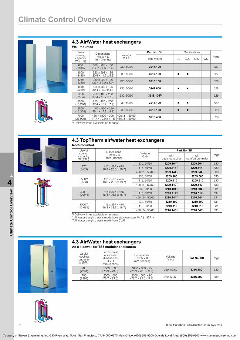
Climate Control Overview
76 Rittal Handbook 31/Climate Control Systems
A
4.
Clim
ate
Con
trol
Ove
rvie
w
4.3 Air/Water heat exchangersWall-mounted
Useful cooling
capacityW (BTU)
DimensionsH x W x D
mm (inches)
VoltageV, Hz
Part No. SK Certifications
PageWall mount UL CUL DIN GS
600(2049)
500 x 200 x 100(19.7 x 7.9 x 3.9) 230, 50/60 3214.100 627
1000(3415)
520 x 298 x 135(20.5 x 11.7 x 5.3) 230, 50/60 3217.100 � � 627
1250(4269)
950 x 200 x 100(37.4 x 7.9 x 3.9) 230, 50/60 3215.100 628
1540(5259)
825 x 380 x 105(32.4 x 15.0 x 4.1) 230, 50/60 3247.000 � � 628
2250(7384)
950 x 400 x 200(37.4 x 15.7 x 7.9) 230, 50/60 3218.1041) 629
3000(10,246)
950 x 400 x 200(37.4 x 15.7 x 7.9) 230, 50/60 3218.100 � � 629
4500(15,368)
1400 x 450 x 250(55.1 x 17.7 x 9.8) 230, 50/60 3216.100 � � 629
7000(23,905)
450 x 1800 x 300(17.7 x 70.9 x 11.8)
400, 3~, 50/60480, 3~, 50/60 3216.480 629
1) Delivery times available on request.
4.3 TopTherm air/water heat exchangersRoof-mounted
Useful cooling capacityW (BTU)
DimensionsH x W x D
mm (inches)
VoltageV, Hz
Part No. SKPageWith
basic controllerWith
comfort controller
1875*(6403)
415 x 597 x 475(16.3 x 23.5 x 18.7)
230, 50/60 3209.1041) 3209.5041) 630
115, 50/60 3209.1141) 3209.5141) 630
400, 2~, 50/60 3209.1441) 3209.5441) 630
2500**(8538)
415 x 597 x 475(16.3 x 23.5 x 18.7)
230, 50/60 3209.100 3209.500 630
115, 50/60 3209.110 3209.510 630
400, 2~, 50/60 3209.1401) 3209.5401) 630
3000*(10,246)
415 x 597 x 475(16.3 x 23.5 x 18.7)
230, 50/60 3210.1041) 3210.5041) 631
115, 50/60 3210.1141) 3210.5141) 631
400, 2~, 50/60 3210.1441) 3210.5441) 631
4000**(13,661)
415 x 597 x 475(16.3 x 23.5 x 18.7)
230, 50/60 3210.100 3210.500 631
115, 50/60 3210.110 3210.510 631
400, 2~, 50/60 3210.1401) 3210.5401) 631 1) Delivery times available on request.* All water-carrying parts made from stainless steel V4A (1.4571)**All water-carrying parts made from CuAl
4.3 Air/Water heat exchangersAs a sidewall for TS8 modular enclosures
Useful cooling capacityW (BTU)
For modularenclosure
dimensionsH x D
mm (inches)
DimensionsH x W x D
mm (inches)
VoltageV, Hz Part No. SK Page
700(2391)
1800 x 600 (70.9 x 23.6)
1800 x 600 x 95(70.9 x 23.6 x 3.7) 230, 50/60 3316.180 632
700(2391)
2000 x 600 (78.7 x 23.6)
2000 x 600 x 95(78.7 x 23.6 x 3.7) 230, 50/60 3316.200 632
Courtesy of Steven Engineering, Inc.-230 Ryan Way, South San Francisco, CA 94080-6370-Main Office: (650) 588-9200-Outside Local Area: (800) 258-9200-www.stevenengineering.com

Climate Control Overview
77Rittal Handbook 31/Climate Control Systems
A
4.
Clim
ate
Con
trol
Ove
rvie
w
4.3 TopTherm air/air heat exchangersWall-mounting
Specific thermal capacity
DimensionsH x W x D
mm (inches)
VoltageV, Hz Part No. SK
CertificationsPage
UL CUL DIN GS
12.0 W/C200 x 400 x 146(7.8 x 15.7 x 4.8)
230, 50/60 3125.800 –
17.5 W/C550 x 280 x 150
(21.7 x 11.0 x 5.9)230, 50/60 3126.100 � � 633115, 50/60 3126.115 � � 633
30.0 W/C950 x 400 x 205
(37.4 x 15.7 x 8.1)230, 50/60 3127.100 � � 633
115, 50/60 3127.115 � � 633
45.0 W/C950 x 400 x 225
(37.4 x 15.7 x 8.9)230, 50/60 3128.100 � � 633
115, 50/60 3128.115 � � 633
60.0 W/C950 x 400 x 225
(37.4 x 15.7 x 8.9)230, 50/60 3129.100 � � 633
115, 50/60 3129.115 � � 633
62.0 W/C400 x 1360 x 110(15.7 x 53.5 x 4.3)
230, 50/60 3129.800 –
90.0 W/C1580 x 400 x 215(62.2 x 15.7 x 8.5)
230, 50/60 3130.100 � � 634
115, 50/60 3130.115 � � 634
4.4 Filter fan unitAir displacement,
unimpeded air flowVoltageV, Hz Part No. SK
CertificationsPage
UL CUL DIN GS CSA
20/25 m3/h(12/15 cfm)
230, 50/60 3321.107 � � 636
115, 50/60 3321.117 � � 636
20 m3/h(12 cfm)
24 (DC) 3321.027 � � 636
48 (DC) 3321.0471) � � 636
55/66 m3/h(32/39 cfm)
230, 50/60 3322.107 � � � 636
115, 50/60 3322.117 � � � 636
55 m3/h(32 cfm)
24 (DC) 3322.027 � � 636
48 (DC) 3322.0471) � � 636
105/120 m3/h(62/71 cfm)
230, 50/60 3323.107 � � � 637
115, 50/60 3323.117 � � � 637
105 m3/h(62 cfm)
24 (DC) 3323.027 � � � 637
48 (DC) 3323.0471) � � 637
160/180 m3/h(94/106 cfm)
230, 50/60 3324.107 � � � 637
115, 50/60 3324.117 � � � 637
180 m3/h(106 cfm)
24 (DC) 3324.027 � � � 637
48 (DC) 3324.0471) � � 637
230/265 m3/h(135/156 cfm)
230, 50/60 3325.107 � � � 638
115, 50/60 3325.117 � � � 638
230 m3/h(135 cfm)
24 (DC) 3325.027 � � � 638
48 (DC) 3325.0471) � � 638
550/600 m3/h(324/353 cfm)
230, 50/60 3326.107 � � � 639
115, 50/60 3326.117 � � � 639
700/720 m3/h(412/424 cfm)
230, 50/60 3327.107 � � 639
115, 50/60 3327.117 � � 639
400/460, 3~, 50/60 3327.147 � � 639
1160 m3/h(680 cfm)
230, 50/60 9964.986115, 50/60 9964.980
1) Delivery times available on request.
Courtesy of Steven Engineering, Inc.-230 Ryan Way, South San Francisco, CA 94080-6370-Main Office: (650) 588-9200-Outside Local Area: (800) 258-9200-www.stevenengineering.com

Climate Control Overview
78 Rittal Handbook 31/Climate Control Systems
A
4.
Clim
ate
Con
trol
Ove
rvie
w
4.4 Filter fan unit – EMCAir displacement,
unimpeded air flowVoltageV, Hz Part No. SK
CertificationsPage
UL CUL DIN GS CSA
20/25 m3/h(12/15 cfm)
230, 50/60 3321.607 � � 640
115, 50/60 3321.6171) � � 640
55/66 m3/h(32/39 cfm)
230, 50/60 3322.607 � � 640
115, 50/60 3322.6171) � � 640
105/120 m3/h(62/71 cfm)
230, 50/60 3323.607 � � 640
115, 50/60 3323.6171) � � 640
160/180 m3/h(94/106 cfm)
230, 50/60 3324.607 � � 641
115, 50/60 3324.6171) � � 641
230/265 m3/h(135/156 cfm)
230, 50/60 3325.607 � � 641
115, 50/60 3325.617 � � 641
550/600 m3/h(324/353 cfm)
230, 50/60 3326.607 � � 641
115, 50/60 3326.6171) � � 641
700/720 m3/h(412/424 cfm)
230, 50/60 3327.607 � � 641
115, 50/60 3327.6171) � � 641 1) Delivery times available on request.
4.5 Rack-mounted air conditionersUseful cooling
capacityW (BTU)
DimensionsH x W x D
mm (inches)
VoltageV, Hz Part No. SK Page
1000(3415)
266 x 445 x 542(10.5 x 17.5 x 21.3)
115, 50/60 3278.1341) 644
230, 50/60 3292.134 644 1) Delivery times available on request.
4.5 Rack-mounted fanAir
displacement, unimpeded
air flow
No. offans
Distance between
axes mm (inches)
VoltageV, Hz
Part No. SK
Certifications
PageUL CUL DIN GS VDE
250 m3/h(147 cfm) 3 85 (3.3) 36 (DC) – 72 (DC) 9769.0021) 645
320 m3/h(188 cfm)
2 85 (3.3) 24 (DC) 3340.0241) � � � 645
2 85 (3.3) 115 (AC), 50/60 3340.1151) � � � 645
2 85 (3.3) 230 (AC), 50/60 3340.230 � � � 645
480 m3/h(283 cfm)
3 85 (3.3) 24 (DC) 3341.0241) � � � 645
3 105 (4.1) 24 (DC) 3342.024 � � � 645
3 85 (3.3) 115 (AC), 50/60 3341.115 � � � 645
3 105 (4.1) 115 (AC), 50/60 3342.1151) � � � 645
3 85 (3.3) 230 (AC), 50/60 3341.230 � � � 645
3 105 (4.1) 230 (AC), 50/60 3342.230 � � � 645
3 105 (4.1) 24 (DC)115 – 230 (AC), 50/60 3342.500 � � � 645
1) Delivery times available on request.
Courtesy of Steven Engineering, Inc.-230 Ryan Way, South San Francisco, CA 94080-6370-Main Office: (650) 588-9200-Outside Local Area: (800) 258-9200-www.stevenengineering.com

Climate Control Overview
79Rittal Handbook 31/Climate Control Systems
A
4.
Clim
ate
Con
trol
Ove
rvie
w
4.5 Vario rack-mounted fanAir
displacement, unimpeded
air flow
No. offans
Distance between axes mm (inches)
VoltageV, Hz
Part No. SK
Certifications
PageUL CUL DIN GS VDE
320 m3/h(188 cfm)
2 85 (3.3) 24 (DC) 3350.0241) � � � 645
2 85 (3.3) 115 (AC), 50/60 3350.1151) � � � 645
2 85 (3.3) 230 (AC), 50/60 3350.230 � � � 645
480 m3/h(283 cfm)
3 85 (3.3) 24 (DC) 3351.0241) � � � 645
3 105 (4.1) 24 (DC) 3352.0241) � � � 645
3 85 (3.3) 115 (AC), 50/60 3351.1151) � � � 645
3 105 (4.1) 115 (AC), 50/60 3352.1151) � � � 645
3 85 (3.3) 230 (AC), 50/60 3351.230 � � � 645
3 105 (4.1) 230 (AC), 50/60 3352.230 � � � 645
3 105 (4.1)24 (DC)
115 – 230 (AC), 50/60
3352.5001) � � � 645
1) Delivery times available on request.
4.5 Centrifugal fanAir
displacement, unimpeded
air flow
DimensionsH x W x D
mm (inches)
VoltageV, Hz Part No. SK Page
320 m3/h(188 cfm)
87 x 482 x 158(3.4 x 19.0 x 6.2)
115, 50/60 3145.000 646
230, 50/60 3144.000 646
4.5 Roof-Mounted fan and vent attachmentFor TS8 modular enclosures
Air displacement, unimpeded air flow
VoltageV, Hz
Required mounting cutoutW x D
mm (inches)Part No. SK Page
400 m3/h(235 cfm)
115, 50/60 475 x 260 (18.7 x 10.2) 3149.410 647
230, 50/60 475 x 260 (18.7 x 10.2) 3149.420 647
400, 3~, 50/60 460, 3~, 60 475 x 260 (18.7 x 10.2) 3149.440 647
800 m3/h(471 cfm)
115, 50/60 475 x 260 (18.7 x 10.2) 3149.810 647
230, 50/60 475 x 260 (18.7 x 10.2) 3149.820 647
400, 3~, 50/60 460, 3~, 60 475 x 260 (18.7 x 10.2) 3149.840 647
Without motor 490 x 390 (19.3 x 15.4) 8801.380 647
4.5 Roof-Mounted fansAir displacement,
unimpeded air flowVoltageV, Hz
Required mounting cutoutW x D mm (inches) Part No. SK Page
360 m3/h (212 cfm)230, 50/60
345 x 265 (13.6 x 10.4)3149.007 647
115, 50/60 3169.007 647
Without fan motor 345 x 265 (13.6 x 10.4) 3148.007 647
625 m3/h (360 cfm) 230, 50/60 345 x 265 (13.6 x 10.4) 9966.815 + 9967.776625 m3/h (360 cfm) 115, 50/60 345 x 265 (13.6 x 10.4) 9966.814 + 9967.775 EMC
Courtesy of Steven Engineering, Inc.-230 Ryan Way, South San Francisco, CA 94080-6370-Main Office: (650) 588-9200-Outside Local Area: (800) 258-9200-www.stevenengineering.com

Climate Control Overview
80 Rittal Handbook 31/Climate Control Systems
A
4.
Clim
ate
Con
trol
Ove
rvie
w
4.5 Roof-Mounted fansFor TS/FR(i) for the office sector
Air displacement, unimpeded
air flow
VoltageV, Hz
VersionDimensionsH x W x D
mm (inches)
Part No. SK
Certifications
PageWithroof plate
Withoutroof plate
UL CUL DIN GS CSA
1,500 m3/h(883 cfm)
115, 50/60 � 240 x 800 x 800(9.4 x 31.5 x 31.5)
3164.610 648
230, 50/60 � 3164.620 648
1,500 m3/h(883 cfm)
115, 50/60 � 240 x 800 x 900(9.4 x 31.5 x 35.4)
3164.810 648
230, 50/60 � 3164.820 648
1,500 m3/h(883 cfm)
115, 50/60 � 227 x 511 x 511(8.9 x 20.1 x 20.1)
3164.115 648
230, 50/60 � 3164.230 648
4.6 Enclosure heatersContinuous
thermal outputfor
Tu = 20°C (68°F)W
VoltageV, Hz Part No. SK
Certifications
PageUL CUL DIN GS VDE
10 110 – 240 (AC/DC) 3105.000 � � � 655
20 110 – 240 (AC/DC) 3106.000 � � � 655
30 110 – 240 (AC/DC) 3115.000 � � � 655
50 110 – 240 (AC/DC) 3116.000 � � � 655
130 110 – 240 (AC/DC) 3107.000 + 3108.000 � � � 655
300 230, 50/60 3102.000 (incl. fan) � � � 655
300 115, 50/60 3102.110 � � � 655
4.6 Enclosure heatersFor CS outdoor enclosures
Continuous thermal output
Tu = 20°C (68°F) W
VoltageV, Hz
Installation DimensionsH x W x D
mm (inches)
Part No. CS
CertificationsPageIn the
enclosure19″ rails UL CUL DIN GS VDE
1000 230, 50/60 � – 82 x 325 x 220(3.2 x 12.8 x 8.7) 9769.015 � � 656
600 230, 50/60 – � 87.2 x 482.6 x 236(3.4 x 19.0 x 9.3) 9769.023 656
4.8 Liquid cooling packageCooling capacity
W (BTU)
DimensionsH x W x D
mm (inches)
VoltageV, Hz
Part No. SK Page
Enclosure + 3 modules4000 (13,661) 2000 x 300 x 1000 (78.7 x 11.8 x 39.4) 230, 50/60 3301.230 672
4000 (13,661) 2000 x 300 x 1000 (78.7 x 11.8 x 39.4) 115, 50/60 3301.210 672
Cooling module, single4000 (13,661) 250 x 550 x 950 (9.8 x 21.7 x 37.4) 230, 50/60 3301.250 672
4.8 Rack-mounted chillerSpecific
thermal capacityW (BTU)
DimensionsH x W x D
mm (inches)
VoltageV, Hz Part No. SK Page
1000 (3415) 442 x 175 x 751(17.4 x 6.9 x 29.6) 230, 50/60 3301.260 673
Delivery times available on request.
Courtesy of Steven Engineering, Inc.-230 Ryan Way, South San Francisco, CA 94080-6370-Main Office: (650) 588-9200-Outside Local Area: (800) 258-9200-www.stevenengineering.com

IT Solutions
81Rittal Handbook 31/Networking Solutions
A
5.
IT S
olut
ions
IT solutions – perfect and customized. With emerging technologies, network applications place ever increasing demands on the infrastructure at the information hub, and therefore on competent system suppliers. Whether you need a small floor termination enclosure for a fiber-optic network or a combined distribution and component enclosure, the Rittal range has the optimum practical system solution to solve any problem, whatever the application.
● Networking● Server racks● Monitoring● Terminals● Telecom
Detailed information may be found in Handbook 31 on pages 676 – 811 or on our website: www.rittal-corp.com.The latest status of approvals may be found on the Internet at: log onto www.rittal-corp.com.
5.1 NetworkingNetwork enclosures based on TE 7000
Dimensions in mm (inches)
U
Part No. TE, RAL 7035 (light gray)
PageHeight Width Depth
19″ distance between levels as delivered
Depth
Side panels
With Without
600 (23.6) 600 (23.6) 600 (23.6) 495 (19.5) 11 7000.390 – 682
600 (23.6) 600 (23.6) 800 (31.5) 495 (19.5) 11 7000.410 – 682
1200 (47.2) 600 (23.6) 600 (23.6) 495 (19.5) 24 7000.430 – 682
1200 (47.2) 600 (23.6) 800 (31.5) 495 (19.5) 24 7000.440 – 682
1200 (47.2) 800 (31.5) 600 (23.6) 495 (19.5) 24 7000.450 – 685
1200 (47.2) 800 (31.5) 800 (31.5) 495 (19.5) 24 7000.4601) – 685
2000 (78.7) 600 (23.6) 600 (23.6) 495 (19.5) 42 7000.5002) 7000.502 682
2000 (78.7) 600 (23.6) 800 (31.5) 495 (19.5) 42 7000.5103) – 682
2000 (78.7) 800 (31.5) 600 (23.6) 495 (19.5) 42 7000.5204) – 685
2000 (78.7) 800 (31.5) 800 (31.5) 495 (19.5) 42 7000.5301) 5) 7000.5321) 685
2200 (86.6) 600 (23.6) 600 (23.6) 495 (19.5) 47 7000.560 7000.562 682
2200 (86.6) 600 (23.6) 800 (31.5) 495 (19.5) 47 7000.570 – 682
2200 (86.6) 800 (31.5) 600 (23.6) 495 (19.5) 47 7000.580 – 685
2200 (86.6) 800 (31.5) 800 (31.5) 495 (19.5) 47 7000.590 7000.592 685 1) Part No. TE pre-configured with base/plinth, grounding and accessory kit: Height 1200 mm (47.2″): 7000.840,
Height 2000 mm (78.7″): with sidewall 7000.850, without sidewall 7000.8522) Part No. TE in RAL 9005 (jet black): 7000.505 3) Part No. TE in RAL 9005 (jet black): 7000.5154) Part No. TE in RAL 9005 (jet black): 7000.525 5) Part No. TE in RAL 9005 (jet black): 7000.535
Network enclosures based on Rittal TS 8 modular enclosure, pre-configuredDimensions
mm (inches)U
Part No. DKPage
Height Width DepthSide panels
With Without
Enclosure type V1
1200 (47.2) + 100 (3.9) 600 (23.6) 600 (23.6) 24 7830.100 – 687
Enclosure type V2
1800 (70.9) + 100 (3.9) 800 (31.5) 800 (31.5) 38 7830.800 7830.850 687
2000 (78.7) + 100 (3.9) 800 (31.5) 800 (31.5) 42 7830.200 7830.250 687
2200 (86.6) + 100 (3.9) 800 (31.5) 800 (31.5) 47 7830.220 7830.270 687
Enclosure type V3
1200 (47.2) + 100 (3.9) 800 (31.5) 900 (35.4) 24 7830.120 – 689
2000 (78.7) + 100 (3.9) 800 (31.5) 900 (35.4) 42 7830.300 7830.350 689
2000 (78.7) + 100 (3.9) 800 (31.5) 1000 (39.4) 42 7830.330 7830.335 689
2200 (86.6) + 100 (3.9) 800 (31.5) 900 (35.4) 47 7830.320 7830.370 689
2200 (86.6) + 100 (3.9) 800 (31.5) 1000 (39.4) 47 7830.340 7830.380 689
Enclosure type V4
2000 (78.7) + 100 (3.9) 800 (31.5) 800 (31.5) 42 7830.400 – 691
Enclosure type V5
2000 (78.7) + 100 (3.9) + 25 (1.0) 800 (31.5) 800 (31.5) 42 7830.500 7830.550 691
Enclosure type V6
2000 (78.7) + 100 (3.9) + 25 (1.0) 800 (31.5) 800 (31.5) 40 7830.660 7830.670 691
Courtesy of Steven Engineering, Inc.-230 Ryan Way, South San Francisco, CA 94080-6370-Main Office: (650) 588-9200-Outside Local Area: (800) 258-9200-www.stevenengineering.com

IT Solutions
82 Rittal Handbook 31/Networking Solutions
A
5.
IT S
olut
ions
5.1 NetworkingNetwork enclosures, based on Rittal TS 8 modular enclosure, types 1 and 2
Approvals: ● UL● C-UL
Dimensions mm (inches) U
Part No. DKPage
Height Width Depth Type 1 Type 2
800 (31.5) 600 (23.6) 600 (23.6) 15 7820.100 7821.100 693
1000 (39.4) 600 (23.6) 600 (23.6) 20 7820.200 7821.200 693
1000 (39.4) 800 (31.5) 600 (23.6) 20 7820.240 7821.240 693
1200 (47.2) 600 (23.6) 600 (23.6) 24 7820.300 7821.300 693
1200 (47.2) 800 (31.5) 600 (23.6) 24 7820.340 7821.340 693
1200 (47.2) 800 (31.5) 800 (31.5) 24 7820.350 – 693
1200 (47.2) 800 (31.5) 900 (35.4) 24 7820.355 7821.355 693
1200 (47.2) 800 (31.5) 1000 (39.4) 24 7820.360 – 693
1400 (55.1) 600 (23.6) 600 (23.6) 29 7820.400 7821.400 693
1400 (55.1) 600 (23.6) 800 (31.5) 29 7820.410 7821.410 693
1400 (55.1) 800 (31.5) 600 (23.6) 29 7820.440 7821.440 693
1600 (63.0) 600 (23.6) 600 (23.6) 33 7820.500 7821.500 693
1600 (63.0) 600 (23.6) 800 (31.5) 33 7820.510 7821.510 693
1600 (63.0) 800 (31.5) 600 (23.6) 33 7820.540 7821.540 693
1800 (70.9) 600 (23.6) 600 (23.6) 38 7820.600 7821.600 693
1800 (70.9) 600 (23.6) 800 (31.5) 38 7820.610 7821.610 693
1800 (70.9) 600 (23.6) 900 (35.4) 38 7820.620 7821.620 694
1800 (70.9) 800 (31.5) 600 (23.6) 38 7820.640 7821.640 694
1800 (70.9) 800 (31.5) 800 (31.5) 38 7820.650 7821.650 694
1800 (70.9) 800 (31.5) 1000 (39.4) 38 7820.670 7821.670 694
2000 (78.7) 600 (23.6) 600 (23.6) 42 7820.700 7821.700 694
2000 (78.7) 600 (23.6) 800 (31.5) 42 7820.710 7821.710 694
2000 (78.7) 800 (31.5) 600 (23.6) 42 7820.740 7821.740 694
2000 (78.7) 800 (31.5) 800 (31.5) 42 7820.750 7821.750 694
2000 (78.7) 800 (31.5) 900 (35.4) 42 7820.760 7821.760 694
2000 (78.7) 800 (31.5) 1000 (39.4) 42 7820.770 7821.770 694
2200 (86.6) 600 (23.6) 600 (23.6) 47 7820.800 7821.800 694
2200 (86.6) 600 (23.6) 800 (31.5) 47 7820.810 7821.810 694
2200 (86.6) 800 (31.5) 600 (23.6) 47 7820.840 7821.840 694
2200 (86.6) 800 (31.5) 800 (31.5) 47 7820.850 7821.850 694
2200 (86.6) 800 (31.5) 900 (35.4) 47 7820.860 7821.860 694
2200 (86.6) 800 (31.5) 1000 (39.4) 47 7820.870 7821.870 694
* For US versions consult the IT Connections catalog.
Network enclosures based on Rittal FlexRack(i), pre-configuredDimensionsmm (inches)
U
Part No. FR(i)Page
Height Width Depth1) Side panels
With Without
600 (23.6) + 100 (3.9) 600 (23.6) 805 (31.7) 11 7855.480 – 703
600 (23.6) + 100 (3.9) 600 (23.6) 1005 (39.6) 11 7855.500 – 703
1200 (47.2) + 100 (3.9) 600 (23.6) 1005 (39.6) 25 7855.510 – 703
2000 (78.7) + 100 (3.9) 800 (31.5) 805 (31.7) 42 7855.550 7855.540 703
2000 (78.7) + 100 (3.9) 800 (31.5) 1005 (39.6) 42 7855.570 7855.560 703 1) Nominal size excluding lock systems.
Courtesy of Steven Engineering, Inc.-230 Ryan Way, South San Francisco, CA 94080-6370-Main Office: (650) 588-9200-Outside Local Area: (800) 258-9200-www.stevenengineering.com

IT Solutions
83Rittal Handbook 31/Networking Solutions
A
5.
IT S
olut
ions
5.1 NetworkingNetwork enclosures based on Rittal FlexRack(i)
Dimensions mm (inches) U Part No. FR(i) Page
Height Width Depth 1)
600 (23.6) 600 (23.6) 605 (23.8) 11 7855.610 705
600 (23.6) 600 (23.6) 1005 (39.6) 11 7855.620 705
1200 (47.2) 600 (23.6) 605 (23.8) 24 7855.630 705
1200 (47.2) 800 (31.5) 805 (31.7) 24 7855.690 705
1200 (47.2) 600 (23.6) 1005 (39.6) 24 7855.640 705
1800 (70.9) 600 (23.6) 605 (23.8) 38 7855.650 705
1800 (70.9) 800 (31.5) 805 (31.7) 38 7855.700 705
2000 (78.7) 600 (23.6) 605 (23.8) 42 7855.660 705
2000 (78.7) 600 (23.6) 1005 (39.6) 42 7855.670 705
2000 (78.7) 800 (31.5) 805 (31.7) 42 7855.710 705
2000 (78.7) 800 (31.5) 1005 (39.6) 42 7855.720 705
2200 (86.6) 600 (23.6) 1005 (39.6) 47 7855.680 705
2200 (86.6) 800 (31.5) 805 (31.7) 47 7855.730 705
2200 (86.6) 800 (31.5) 1005 (39.6) 47 7855.740 705 1) Nominal size excluding lock systems.
Termination racks based on Rittal Data RackDimensions
mm (inches) U Part No. DK PageHeight Width Depth
1499.5 (59.0) 550 (21.7) 750 (29.5) 31 7391.000 708
1721.8 (67.8) 550 (21.7) 750 (29.5) 36 7396.000 708
1899.5 (74.8) 550 (21.7) 750 (29.5) 40 7400.000 708
2121.8 (83.5) 550 (21.7) 750 (29.5) 45 7445.000 708
Mobile workstation, Rittal RiLab
Approvals: ● TÜV tested safety
Dimensions mm (inches) Part No. DK Page
Height Width Depth
Type 1
820 (32.3) 714 (28.1) 625 (24.6) 7600.100 711
Type 2
1108 (43.6) 714 (28.1) 625 (24.6) 7600.200 711
Type 3
1428 (56.22) 714 (28.1) 625 (24.6) 7600.300 711
Courtesy of Steven Engineering, Inc.-230 Ryan Way, South San Francisco, CA 94080-6370-Main Office: (650) 588-9200-Outside Local Area: (800) 258-9200-www.stevenengineering.com

IT Solutions
84 Rittal Handbook 31/Networking Solutions
A
5.
IT S
olut
ions
5.2 NetworkingRNC enclosure
Dimensions mm (inches) U Mounting
positionPart No. DK
PageHeight Width Depth Single Bulk pack
255 (10.0) 342 (13.5) 280 (11.0) 4 horizontal 7870.100 7870.500 716
390 (15.4) 342 (13.5) 280 (11.0) 8 horizontal 7870.200 7870.510 716
490 (19.3) 342 (13.5) 400 (15.7) 6 vertical 7870.300 7870.520 716
RNC universal enclosureDimensions
mm (inches) U 1/2 19″
U 19″
Part No. DKPage
Height Width Depth Single Bulk pack
500 (19.7) 350 (13.8) 350 (13.8) 10 5 7870.350 7870.530 717
Wall-mounted enclosure, based on Rittal QuickBox, 6 – 21UDimensions
mm (inches)U/SU
Part No. DKPage
Height Width Depth With viewing door
With sheet steel door
362 (14.3) 600 (23.6) 300 (11.8) 6/10 7502.013 – 718
362 (14.3) 600 (23.6) 400 (15.7) 6/10 7502.014 7502.114 718
362 (14.3) 600 (23.6) 600 (23.6) 6/10 7502.016 – 718
495 (19.5) 600 (23.6) 300 (11.8) 9/15 7502.023 7502.123 718
495 (19.5) 600 (23.6) 400 (15.7) 9/15 7502.024 7502.124 718
495 (19.5) 600 (23.6) 600 (23.6) 9/15 7502.026 7502.126 718
628 (24.7) 600 (23.6) 400 (15.7) 12/20 7502.034 7502.134 718
628 (24.7) 600 (23.6) 500 (19.7) 12/20 7502.035 – 718
628 (24.7) 600 (23.6) 600 (23.6) 12/20 7502.036 7502.126 718
762 (30.0) 600 (23.6) 400 (15.7) 15/26 7502.044 7502.144 719
762 (30.0) 600 (23.6) 500 (19.7) 15/26 7502.045 – 719
762 (30.0) 600 (23.6) 600 (23.6) 15/26 7502.046 7502.146 719
895 (35.2) 600 (23.6) 400 (15.7) 18/31 7502.054 – 719
895 (35.2) 600 (23.6) 500 (19.7) 18/31 7502.055 – 719
895 (35.2) 600 (23.6) 600 (23.6) 18/31 7502.056 – 719
1028 (40.5) 600 (23.6) 400 (15.7) 21/36 7502.064 – 719
1028 (40.5) 600 (23.6) 600 (23.6) 21/36 7502.066 7502.166 719
Courtesy of Steven Engineering, Inc.-230 Ryan Way, South San Francisco, CA 94080-6370-Main Office: (650) 588-9200-Outside Local Area: (800) 258-9200-www.stevenengineering.com

IT Solutions
85Rittal Handbook 31/Networking Solutions
A
5.
IT S
olut
ions
5.2 NetworkingWall-mounted enclosure, based on Rittal QuickBox with vertical 19″angles
Dimensions mm (inches) U
vertical Part No. DK PageHeight Width Depth
631 (24.8) 600 (23.6) 210 (8.3) 3 7502.630 720
631 (24.8) 600 (23.6) 360 (14.2) 6 7502.660 720
Wall-mounted enclosure, based on Rittal AE, with pull-out frameDimensions
mm (inches)U
sides,vertical
U front Part No. DK Page
Height Width Depth
600 (23.6) 600 (23.6) 350 (13.8) 4 10 7644.000 721
Wall-mounted enclosure, based on Rittal AE
Approvals: ● UL● CSA● Lloyds Register of Shipping
Dimensions mm (inches) U Part No. DK Page
Height Width Depth
380 (15.0) 600 (23.6) 350 (13.8) 8 7641.000 722
600 (23.6) 600 (23.6) 350 (13.8) 13 7643.000 722
760 (29.9) 600 (23.6) 350 (13.8) 16 7645.000 722
Office termination, 2 U and 4 U, for fiber-optic and copper cablesDimensions
mm (inches) U Part No. DK PageHeight Width Depth
504 (19.8) 400 (15.7) 106 (4.2) 2 7245.000 723
504 (19.8) 400 (15.7) 195 (7.7) 4 7245.400 723
Small fiber-optic terminationsDimensions
mm (inches) Number of fibers Part No. DK PageHeight Width Depth
500 (19.7) 500 (19.7) 120 (4.7) 1 – 48 7452.035 724
900 (35.4) 500 (19.7) 120 (4.7) 1 – 96 7453.035 724
Courtesy of Steven Engineering, Inc.-230 Ryan Way, South San Francisco, CA 94080-6370-Main Office: (650) 588-9200-Outside Local Area: (800) 258-9200-www.stevenengineering.com

IT Solutions
86 Rittal Handbook 31/Networking Solutions
A
5.
IT S
olut
ions
5.2 NetworkingSmall fiber-optic termination, based on Rittal AE
Dimensions mm (inches) Number of fibers Part No. DK Page
Height Width Depth
500 (19.7) 400 (15.7) 155 (6.1) 1 – 48 7454.000 725
Fiber-optic marshalling enclosureDimensions
mm (inches) Number of fibers Part No. DK PageHeight Width Depth
250 (9.8) 400 (15.7) 120 (4.7) 1 – 24 7247.000 726
Small fiber-optic termination, polycarbonateDimensions
mm (inches) Number of fibers Part No. DK PageHeight Width Depth
254 (10.0) 180 (7.1) 90 (3.5) 1 – 24 7451.000 727
Wall-mounted enclosure, based on Rittal EL, 3-part, pre-configured, depth 573 (22.5″)
Approvals (for viewing doors only) ● UL● C-UL
Dimensions mm (inches) U
Part No. DKPage
Height Width Depth With viewing door With slotted metal door 1)
478 (18.8) 600 (23.6) 572.5 (22.5) 9 7709.735 7709.835 728
746 (29.4) 600 (23.6) 572.5 (22.5) 15 7715.735 7715.835 728
1012 (39.8) 600 (23.6) 572.5 (22.5) 21 7721.735 7721.835 728 1) Extended delivery times.Additional features of the pre-configured wall-mounted enclosure: Earth rail with star grounding, one outlet filter on both the left and right, 4 wall mounting brackets.
Wall-mounted enclosure, based on Rittal EL, 3-part, with punched rails, depth 473 (18.6″)
Approvals: ● UL● C-UL
Dimensions mm (inches) U Part No. DK Page
Height Width Depth
345 (13.6) 600 (23.6) 472.5 (18.6) 6 7706.135 729
478 (18.8) 600 (23.6) 472.5 (18.6) 9 7709.135 729
612 (24.1) 600 (23.6) 472.5 (18.6) 12 7712.135 729
746 (29.4) 600 (23.6) 472.5 (18.6) 15 7715.135 729
878 (34.6) 600 (23.6) 472.5 (18.6) 18 7718.135 729
1012 (39.8) 600 (23.6) 472.5 (18.6) 21 7721.135 729
Courtesy of Steven Engineering, Inc.-230 Ryan Way, South San Francisco, CA 94080-6370-Main Office: (650) 588-9200-Outside Local Area: (800) 258-9200-www.stevenengineering.com

IT Solutions
87Rittal Handbook 31/Networking Solutions
A
5.
IT S
olut
ions
5.2 NetworkingWall-mounted enclosure, based on Rittal EL, 3-part, depth 373 and 473 mm (14.7 and 18.6″),with mounting panel,
Approvals: ● UL● C-UL
Dimensions mm (inches)
UPart No. DK
PagePart No. DK
PageHeight Width mm (inches)
Depth 373 (14.7)mm (inches)
Depth 473 (18.6)
212 (8.3) 600 (23.6) 3 2243.605 730 2253.605 731
345 (13.6) 600 (23.6) 6 2246.605 730 2256.605 731
478 (18.8) 600 (23.6) 9 2249.605 730 2259.605 731
612 (24.1) 600 (23.6) 12 2252.605 730 2262.605 731
746 (29.3) 600 (23.6) 15 2255.605 730 2265.605 731
878 (34.5) 600 (23.6) 18 2258.605 730 2268.605 731
1012 (39.8) 600 (23.6) 21 2261.605 730 2271.605 731
Wall-mounted enclosure, based on Rittal EL, 2-part, depth 369 mm (14.5″)
Approvals: ● TÜV● Russian Maritime Register of Shipping● Lloyds Register of Shipping● VDE
Dimensions mm (inches) U Part No. EL Page
Height Width Depth
380 (15.0) 600 (23.6) 369 (14.5) 6 1919.500 732
600 (23.6) 600 (23.6) 369 (14.5) 11 1920.500 732
760 (29.9) 600 (23.6) 369 (14.5) 14 1926.500 732
5.3 Server racksBased on Rittal TS 8 modular enclosure, pre-configured
Dimensions mm (inches) U
Part No. DKPage
Height Width Depth RAL 70351) RAL 90052)
1200 (47.2) 600 (23.6) 900 (35.4) 24 7831.431 7831.432 737
1200 (47.2) 600 (23.6) 1000 (39.4) 24 7831.433 7831.434 737
2000 (78.7) 600 (23.6) 900 (35.4) 42 7831.436 7831.437 737
2000 (78.7) 600 (23.6) 1000 (39.4) 42 7831.438 7831.439 737
2200 (86.6) 600 (23.6) 900 (35.4) 47 7831.440 7831.441 737
2200 (86.6) 600 (23.6) 1000 (39.4) 47 7831.442 7831.443 737
2000 (78.7) 800 (31.5) 1000 (39.4) 42 7831.446 – 737 1) Light gray2) Jet Black* For US versions consult the IT Connections catalog.
Co-location/ISP based on Rittal TS 8 modular enclosure, pre-configured, multi-doorDimensions
mm (inches) U SUNumber of
front and rear doors
Part No. DKPage
Height Width Depth RAL 70351) RAL 90052)
2200 (86.6) 600 (23.6) 900 (35.4) 2 x 21 2 x 37 2 7831.450 7831.451 737
2200 (86.6) 600 (23.6) 900 (35.4) 2 x 21 2 x 372
(verticallydivided)
7831.457 7831.458 737
2200 (86.6) 600 (23.6) 900 (35.4) 4 x 10 4 x 17 4 7831.460 7831.461 737 1) Light gray2) Jet Black
Courtesy of Steven Engineering, Inc.-230 Ryan Way, South San Francisco, CA 94080-6370-Main Office: (650) 588-9200-Outside Local Area: (800) 258-9200-www.stevenengineering.com

IT Solutions
88 Rittal Handbook 31/Networking Solutions
A
5.
IT S
olut
ions
5.3 Server racksBased on Rittal flexRack(i), pre-configured
Dimensions mm (inches) U Part No. FR(i) Page
Height Width Depth1)
1200 (47.2) 600 (23.6) 1000 (39.4) 24 7855.310 738
1200 (47.2) 600 (23.6) 1200 (47.2) 24 7855.312 738
2000 (78.7) 600 (23.6) 1000 (39.4) 42 7855.330 738
2000 (78.7) 600 (23.6) 1200 (47.2) 42 7855.332 738 1) Nominal size excluding lock systems.
5.3 Server racksBased on Rittal TE 7000
Dimensions mm (inches) U
Part No. TEPage
Height Width Depth RAL 7035 RAL 9005
2000 (78.7) 600 (23.6) 1000 (39.4) 42 7000.882 – 736
2000 (78.7) 600 (23.6) 1000 (39.4) 42 – 7000.885 736
2000 (78.7) 800 (31.5) 1000 (39.4) 42 7000.892 – 736
2000 (78.7) 800 (31.5) 1000 (39.4) 42 – 7000.895 736
Monitor/keyboard unit, 1U15″ 17″
PageRAL 70353)/RAL 90065)
RAL 90054)/RAL 90065)
RAL 70353)/RAL 90065)
RAL 90054)/RAL 90065)
Touchpad
German 9050.100 9050.200 9050.300 9050.4001) 739
English 9050.102 9050.202 9050.3021) 9050.4021) 739
French 9050.1031) 9050.2031) 9050.3031) 9050.4031) 739
TrackballGerman 9050.150 9050.250 9050.350 9050.450 739
International 9050.1512) 9050.2512) 9050.3512) 9050.4512) 739 1) Extended delivery times. 2) International version only available with trackball, without number pad.3) Light gray 4) Jet Black 5) White aluminium
* For US versions consult the IT Connections catalog.
Rittal SSC view 8/SSC view 32 Catfor monitor/keyboard unit, 1U
DimensionsU or mm (inches) No. of
channelsConnections
Video
Video resolution,maximum
(depending on distance)
Bandwidth Part No. DK PageHeight Width Depth
1U 19″ 140 (5.5) 8 VGA/HD15 1280 x 1024 @ 85 Hz 200 MHz 7552.000 740
1U 19″ 140 (5.5) 32 Cat 5 1920 x 1440 @ 75 Hz 250 MHz 7552.100 740
Rittal SSCmini/SSCmulti
Rittal Server Switch Control SSC
No. of computers in stand-alone
mode
Numberof localoperatorconsoles
Video resolution, maximum(depending on distance)
at 85 HzBandwidth Part No. DK Page
SSCmini 4 4 1 1600 x 1200 250 MHz 7551.000 741
SSCmulti 4 4 1 1600 x 1200 250 MHz 7551.010 741
SSCmulti 8 8 1 1600 x 1200 250 MHz 7551.020 741
SSCmuti 16 16 1 1600 x 1200 250 MHz 7551.030 741
Courtesy of Steven Engineering, Inc.-230 Ryan Way, South San Francisco, CA 94080-6370-Main Office: (650) 588-9200-Outside Local Area: (800) 258-9200-www.stevenengineering.com

IT Solutions
89Rittal Handbook 31/Networking Solutions
A
5.
IT S
olut
ions
5.4 PowerPage
Power Distribution Rack PDR 743
Power Distribution Module PDM 743
Power System Module PSM 744
Connection cable 745
Voltage supply 746
5.4 UPS systemsUPS, single-phase U Power
kVA Part No. DK/110 VAC Page
UPS for 19″ racks with integrated battery 2 1 7857.401/.411 753
UPS for 19″ racks with integrated battery 2 1.5 7857.402/.412 753
UPS control unit for 19″ racks (matching battery pack 2/3 kVA is always needed)
2 2 2 7857.403/.413
7857.408/.418 753
UPS control unit for 19″ racks (matching battery pack 2/3 kVA is always needed)
2 2 3 7857.404/.414
7857.408/.418 753
UPS floor standing enclosure with integrated battery – 6 7857.405/.415 753
5.6 MonitoringComputer Multi Control Top Concept CMC-TC CMC-TC main products PU Part No. DK Page
CMC-TC monitoring system master 1 7320.000 769
CMC-TC monitoring system processing unit 1 7320.100 766
CMC-TC sensor unit I/O unit 1 7320.210 764
CMC-TC sensor unit access unit 1 7320.220 765
CMC-TC sensor unit climate unit 1 7320.230 765
CMC-TC display unit 1 7320.490 767
CMC-TC GSM unit 1 7320.820 767
CMC-TC ISDN unit 1 7320.830 768
CMC extension unit 3 x voltage 100 – 230 V AC 1 7200.520 776
Fan Control System FCS 1 7320.810 786
Fan Alarm System FAS 1 7320.811 787
Sensor unit I/O unit
Access unit
Climateunit PU Part No. DK Page
Sensors/actuators:Temperature sensor � � 1 7320.500 773
Smoke alarm � � 1 7320.560 773
Humidity sensor � 1 7320.510 773
Airflow monitor � � 1 7320.550 774
Voltage monitor � � 1 7320.600 774
Voltage monitor with switch output � 1 7320.610 774
Voltage monitor 48 V DC � � 1 7320.620 775
Vibration sensor � 1 7320.540 777
Access sensor(max. 5 sensors in series supported) � � � 2 7320.530 777
CMC-TC motion detector � � 1 7320.570 778
Water sensor � 1 7320.630 778
Analog sensor input module “4 – 20 mA” � 1 7320.520 779
Digital sensor input module � � � 1 7320.580 779
Digital relay output module � 1 7320.590 779
Lock/reader:Electro-magnetic TS 8 handle with master key function � 1 7320.721 781
Electro-magnetic Ergoform-S FR/PS/TC and TE � 1 7320.700 781
Electro-magnetic Ergoform-S QR � 1 7320.710 781
Smart card reader � 1 7320.750 782
Magnetic card reader � 1 7320.760 782
Coded lock � 1 7320.770 782
Universal lock � 1 7320.730 783
Relay output module for room door � 1 7320.740 780
Courtesy of Steven Engineering, Inc.-230 Ryan Way, South San Francisco, CA 94080-6370-Main Office: (650) 588-9200-Outside Local Area: (800) 258-9200-www.stevenengineering.com

IT Solutions
90 Rittal Handbook 31/Networking Solutions
A
5.
IT S
olut
ions
5.7 KiosksITS Arc-Line II
TFT display, 17″
Dimensionsof kiosk enclosures
approximately mm (inches)
Contact sensor(touchscreen)
including controller
Keyboard recessfor use
ofITS keyboards
Part No. ITS Page
Height Width Depth
Basic (sheet steel)
Rear door
1180 (46.5) 550 (21.7) 700 (27.6) � – 9012.100 792
1180 (46.5) 550 (21.7) 700 (27.6) – � 9012.110 792
Front door
1180 (46.5) 550 (21.7) 700 (27.6) � – 9012.200 792
1180 (46.5) 550 (21.7) 700 (27.6) – � 9012.210 792
Classic (stainless steel)
Rear door
1180 (46.5) 550 (21.7) 700 (27.6) � – 9012.300 792
1180 (46.5) 550 (21.7) 700 (27.6) – � 9012.310 792
Front door
1180 (46.5) 550 (21.7) 700 (27.6) � – 9012.400 792
1180 (46.5) 550 (21.7) 700 (27.6) – � 9012.410 792
Accessories see page 800.
ITS Opti-Line IIDimensions
of kiosk enclosuresapproximately mm (inches)
Contact sensor (touchscreen)
including controller
Keyboard supportfor use of
ITS keyboards
Part No. ITS Page
TFT display Height Width Depth
15″ 1500 (59.1) 560 (22.0) 510 (20.0) � – 9006.505 793
15″ 1500 (59.1) 560 (22.0) 580 (22.8) – � 9006.605 793
17″ 1500 (59.1) 560 (22.0) 510 (20.0) � – 9006.705 793
17″ 1500 (59.1) 560 (22.0) 580 (22.8) – � 9006.805 793
Accessories see page 800.
ITS Opti-Desk
TFTdisplay
Dimensions approximately mm (inches) Part No. ITS
Page With worktop Base enclosure only
with front doorDoorand
worktop curved inwards
Doorand
worktopcurved
outwardsHeight Width Depth Height Width Depth
15″ 1500 (59.1) 1000 (39.4) 800 (31.5) 1000 (39.4) 435 (17.1) 530 (20.9) 9021.250 9021.255 794
17″ 1500 (59.1) 1000 (39.4) 800 (31.5) 1000 (39.4) 435 (17.1) 530 (20.9) 9021.270 9021.275 794
Accessories see page 800.
ITS Opti-Wall
TFTdisplay
Enclosure dimensionsapproximately mm (inches)
Contact sensor(touchscreen)
including controller
Keyboard support
for use ofITS keyboards
Part No. ITS PageWidth Height Depth
Part No. 15″ 560 (22.0) 1000 (39.4) 200 (7.9) � – 9020.150 795
15″ 560 (22.0) 1000 (39.4) 400 (15.7) – � 9020.250 795
17″ 560 (22.0) 1000 (39.4) 200 (7.9) � – 9020.170 795
17″ 560 (22.0) 1000 (39.4) 400 (15.7) – � 9020.270 795
Accessories see page 800.
Courtesy of Steven Engineering, Inc.-230 Ryan Way, South San Francisco, CA 94080-6370-Main Office: (650) 588-9200-Outside Local Area: (800) 258-9200-www.stevenengineering.com

IT Solutions
91Rittal Handbook 31/Networking Solutions
A
5.
IT S
olut
ions
5.7 KiosksITS Alpha-Line
Dimensionsincluding base plate and viewing guard
approximately mm (inches)TFT display
15″ Part No. ITS Page
Height Width Depth
Touchscreen 1300 (51.8) 580 (22.8) 540 (21.3) � 9007.105 796
Prepared for keyboard 1300 (51.8) 580 (22.8) 640 (25.2) � 9007.205 796
Accessories see page 800.
ITS Out-Line Wall Enclosure dimensions approximately mm (inches) TFT display
(high brightnessfor outdoor
applications)
Part No. ITS1) Page Body Including all
projecting parts
Height Width Depth Height 2 Width Depth
Touch-screen
1100 (43.3) 480 (18.9) 305 (12.0) 1360 (53.5) 600 (23.6) 305 (12.0) 15″ 9023.150 797
1100 (43.3) 480 (18.9) 305 (12.0) 1360 (53.5) 600 (23.6) 305 (12.0) 17″ 9023.170 797
Prepared for keyboard
1100 (43.3) 480 (18.9) 365 (14.4) 1360 (53.5) 600 (23.6) 365 (14.4) 15″ 9023.250 797
1100 (43.3) 480 (18.9) 365 (14.4) 1360 (53.5) 600 (23.6) 365 (14.4) 17″ 9023.270 797
Accessories see page 800. 1) Climate control needed.
ITS Out-Line Pro TFT display (suitable for
outdooruse with
increasedluminosity)
Dimensions approximately mm (inches)Contact sensor(touchscreen)
includingcontroller
Keyboardsupport for use of ITS keyboards
Part No. ITS 1) Page
Kiosk enclosures Kiosk including roof
Height Width Depth Height Width Depth
15″
2000 (78.7)
650(25.6)
400 (15.7)
2400(94.5)
1000 (39.4)
1000 (39.4)
� – 9022.150 798
15″ – � 9022.250 798
17″ � – 9022.170 798
17″ – � 9022.270 798
Accessories see page 800. 1) Climate control needed.
ITS PC systems, see page 799.
Keyboards, see pages 800/801. * For US versions consult the IT Connections catalog.
Courtesy of Steven Engineering, Inc.-230 Ryan Way, South San Francisco, CA 94080-6370-Main Office: (650) 588-9200-Outside Local Area: (800) 258-9200-www.stevenengineering.com

IT Solutions
92 Rittal Handbook 31/Networking Solutions
A
5.
IT S
olut
ions
5.8 TelecomRack system, based on Rittal TC-Rack
Dimensions mm (inches) U SU Part No. DK Page
Height Width Depth
2200 (86.6) 600 (23.6) 300 (11.8) 46 82 7723.035 803
2200 (86.6) 600 (23.6) 600 (23.6) 46 82 7726.035 803
Small FM terminationsDimensions
mm (inches) FM systems Paired wires Part No. DK PageHeight Width Depth
500 (19.7) 300 (11.8) 120 (4.7) – 100 7052.035 806
500 (19.7) 500 (19.7) 120 (4.7) – 200 7053.035 806
700 (27.6) 500 (19.7) 120 (4.7) – 400 7054.035 806
700 (27.6) 900 (35.4) 120 (4.7) – 800 7055.035 806
Modular FM wall-mounted termination
Approvals: ● UL● CSA● TÜV● Lloyds Register of Shipping● VDE
Dimensions mm (inches) FM systems Paired wires
maximum Part No. DK PageHeight Width Depth
600 (23.6) 600 (23.6) 350 (13.8) 2 sets 340 7011.535 807
760 (29.9) 760 (29.9) 300 (11.8) 2 sets 500 7012.535 807
1000 (39.4) 800 (31.5) 300 (11.8) 3 sets 990 7013.535 807
1200 (47.2) 800 (31.5) 300 (11.8) 3 sets 1170 7014.535 807
Modular FM termination racks
Approvals: ● UL● CSA● TÜV● Lloyds Register of Shipping● VDE
Dimensions mm (inches) FM systems Paired wires
maximum Part No. DK PageHeight Width Depth
2000 (78.7) 600 (23.6) 400 (15.7) 2 1300 7834.060 808
2000 (78.7) 800 (31.5) 400 (15.7) 3 1950 7834.080 808
2000 (78.7) 1200 (47.2) 400 (15.7) 5 3250 7834.120 808
Courtesy of Steven Engineering, Inc.-230 Ryan Way, South San Francisco, CA 94080-6370-Main Office: (650) 588-9200-Outside Local Area: (800) 258-9200-www.stevenengineering.com

Communication Systems
93Rittal Handbook 31/Communications Systems
A
6.
Com
mun
icat
ion
Syst
ems
Communication Systems – Perfect protection in any climateRittal’s expertise in the fields of enclosure technology, climate control, security management and system integration is combined in standard solutions and customized outdoor systems. The specific requirements of mobile communications,IT technology, environmental technology and power distribution are accommodated on a project-specific basis.High-quality materials such as aluminum and zinc-plated sheet steel combine corrosion resistance and protection from vandalism with UV stability and a high level of RF attenuation.
Individual complete solutions using mass-produced modules: ● CS Toptec (twin-walled) ● CS wall-mounted enclosure (enclosure within
an enclosure) ● CS compact enclosure (single-walled) ● CS basic enclosure (single-walled) ● CS modular enclosure (twin-walled) ● CS Indoor Racks● CS Outdoor climate control
Detailed information may be found onHandbook 31 pages 812 – 831 or refer to our website: log onto www.rittal-corp.com.
6.1 CS ToptecDimensions
mm (inches) Part No. CS PageHeight Width Depth
Without climate control module
1200 (47.2) 650 (25.6) 650 (25.6) 9774.100 817
1200 (47.2) 800 (31.5) 650 (25.6) 9774.200 817
1600 (63.0) 650 (25.6) 650 (25.6) 9774.300 817
1600 (63.0) 800 (31.5) 650 (25.6) 9774.400 817
With heat exchanger 85 W/K 105 W/K
1200 (47.2) 800 (31.5) 650 (25.6) 9774.210 9774.2301) 817
1600 (63.0) 800 (31.5) 650 (25.6) 9774.410 9774.4301) 817
With air conditioner 1000 W 1600 W
1200 (47.2) 800 (31.5) 650 (25.6) 9774.250 9774.2701) 817
1600 (63.0) 800 (31.5) 650 (25.6) 9774.450 9774.4701) 817 1) Delivery times available on request.
6.1 CS wall-mounted enclosuresDimensions external/internal
mm (inches) Part No. CS PageHeight Width Depth
522.5/400 (20.6/15.7) 370/300 (14.6/11.8) 210/170 (8.3/6.7) 9791.015 818
560.5/440 (22.1/17.3) 420/350 (16.5/13.8) 210/170 (8.3/6.7) 9791.025 818
700/565 (27.6/22.2) 530/460 (20.9/18.1) 265/220 (10.4/8.7) 9791.035 818
780/580 (30.7/22.8) 630/580 (24.8/22.8) 380/333 (15.0/13.1) 9791.045 818
With rotating frame, 5U, instead of mounting panel
780/580 (30.7/22.8) 630/580 (24.8/22.8) 380/333 (15.0/13.1) 9791.145 818
6.1 CS compact enclosuresDimensions
mm (inches) Enclosure Part No. CS PageHeight Width Depth
Aluminum AlMg3
1100 (43.3) 800 (31.5) 320 (12.6) single-door 9771.115 819
1100 (43.3) 1100 (43.3) 320 (12.6) double-door 9772.115 819
Sheet steel, zinc-plated, passivated
1100 (43.3) 800 (31.5) 320 (12.6) single-door 9771.111 819
1100 (43.3) 1100 (43.3) 320 (12.6) double-door 9772.111 819
Courtesy of Steven Engineering, Inc.-230 Ryan Way, South San Francisco, CA 94080-6370-Main Office: (650) 588-9200-Outside Local Area: (800) 258-9200-www.stevenengineering.com

Communication Systems
94 Rittal Handbook 31/Communications Systems
A
6.
Com
mun
icat
ion
Syst
ems
6.1 Compact enclosures, OutdoorDimensions
mm (inches) Part No. Page
Height Width Depth Sheet steel Stainless steel
1200 (47.2) 800 (31.5) 350 (13.8) 1620.000 1620.100 820
800 (31.5) 1200 (47.2) 350 (13.8) 1621.000 1621.100 820
1200 (47.2) 1200 (47.2) 350 (13.8) 1622.000 1622.100 820
6.1 CS basic enclosuresDimensions
mm (inches) Part No. CSPage
Height Width Depth Without center bar With center bar
Single-door
800 (31.5) 600 (23.6) 400 (15.7) 9783.040 – 821
800 (31.5) 800 (31.5) 400 (15.7) 9783.010 – 821
1200 (47.2) 600 (23.6) 400 (15.7) 9783.050 – 821
1200 (47.2) 600 (23.6) 500 (19.7) 9783.030 – 821
1200 (47.2) 800 (31.5) 400 (15.7) 9783.020 – 821
1200 (47.2) 800 (31.5) 500 (19.7) 9783.110 – 821
1400 (55.1) 600 (23.6) 400 (15.7) 9783.060 – 821
1400 (55.1) 800 (31.5) 400 (15.7) 9783.120 – 821
Double-door
800 (31.5) 1200 (47.2) 400 (15.7) 9784.110 9784.010 822
1200 (47.2) 1200 (47.2) 400 (15.7) 9784.120 9784.020 822
1200 (47.2) 1200 (47.2) 500 (19.7) 9784.140 9784.040 822
1400 (55.1) 1200 (47.2) 400 (15.7) 9784.130 9784.030 822
6.1 CS modular enclosuresDimensions
mm (inches) Part No. CS PageHeight Width Depth
1200 (47.2) 600 (23.6) 600 (23.6) 9751.125 823
1200 (47.2) 800 (31.5) 500 (19.7) 9751.145 823
1200 (47.2) 1200 (47.2) 600 (23.6) 9752.125 823
1600 (63.0) 800 (31.5) 600 (23.6) 9751.165 823
Other modules and size variants may be found on page 824.
6.1 CS Indoor RacksDimensionsmm (inches) Mounting
rails Part No. CS PageHeight Width Depth
2200 (86.6) 600 (23.6) 300 (11.8) 19″ 9790.042 825
2200 (86.6) 600 (23.6) 300 (11.8) Metric 9790.043 825
Courtesy of Steven Engineering, Inc.-230 Ryan Way, South San Francisco, CA 94080-6370-Main Office: (650) 588-9200-Outside Local Area: (800) 258-9200-www.stevenengineering.com

Communication Systems
95Rittal Handbook 31/Communications Systems
A
6.
Com
mun
icat
ion
Syst
ems
6.2 Heat exchanger for CS modular enclosures/compact enclosures
Note:Enclosure heaters for CS outdoor enclosures,see page 80, 656.
Dimensions mm (inches) Mounting
position
Specific thermal output
Heater2) Rated
operatingvoltage
Part No. CS Page
Height Width Depth
95 (3.7) 855 (33.7) 240 (9.4) Roof1) 15 W/K without 48 V DC 9767.012 828
158 (6.2) 470 (18.5) 380 (15.0) Roof 30 W/K without 48 V DC 9764.040 827
390 (15.4) 535 (21.1) 400 (15.7) Roof 60 W/K 400 W 48 V DC 9764.012 827
1005 (39.6) 480 (18.9) 110 (4.3) Door 40 W/K 400 W 48 V DC 9768.032 828
1005 (39.6) 510 (20.1) 150 (5.9) Door 60 W/K 400 W 48 V DC 9768.012 828
1050 (41.3) 445 (17.5) 150 (5.9) Door 85 W/K without 48 V DC 9768.042 828
1050 (41.3) 575 (22.6) 195 (7.7) Door 120 W/K without 48 V DC 9768.062 828
1170 (46.1) 515 (20.3) 151.5 (6.0) Wall 60 W/K 400 W 48 V DC 9763.012 827 1) For compact enclosures 2) Rated operating voltage 230 V AC, 50/60 Hz
6.2 Air conditioners for CS modular enclosures
Approvals CS 9761.032: ● UL● C-UL
Dimensions mm (inches) Mounting
position
Useful cooling capacityEN 814 Voltage Part No.
CS Page
Height Width Depth L35 L35 L35 L50
390 (15.4) 535 (21.1) 400 (15.7) Roof 900 W 750 W 230 V AC, 50/60 Hz 9762.012 829
1170 (46.1) 430 (16.9) 210 (8.7) Door 900 W 650 W 230 V AC, 50/60 Hz 9768.100 829
1070 (42.1) 515 (20.3) 151.5 (6.0) Wall 900 W 750 W 230 V AC, 50/60 Hz 9761.012 829
1132 (44.6) 695 (27.6) 151.5 (6.0) Wall 1400 W 1050 W 230 V AC, 50/60 Hz 9761.032 829
1100 (43.3) 776 (30.6) 250 (9.8) Wall 2500 W 2000 W 230 V AC, 50/60 Hz 9761.042 829
1050 (41.3) 400 (15.7) 310 (12.2) Universalbuilt-in 1500 W 1250 W 230 V AC, 50/60 Hz 9768.150 829
6.2 Climate control units for CS ToptecDimensions
mm (inches) Mountingposition
Useful cooling outputEN 814
Specificthermalcapacity
Voltage Part No. CS Page
Height Width Depth L35 L35 L35 L50
Heat exchanger
1000 (39.4) 500 (19.7) 150 (5.9) Universal built-in – – 85 W/K 48 V DC 9776.100 830
1000 (39.4) 500 (19.7) 260 (10.2) Universal built-in – – 105 W/K 48 V DC 9776.150 830
Air conditioner
1000 (39.4) 500 (19.7) 150 (5.9) Universal built-in 1000 W 650 W – 230 V AC,
50/60 Hz 9776.500 830
1000 (39.4) 500 (19.7) 260 (10.2) Universal built-in 1600 W 1200 W – 230 V AC,
50/60 Hz 9776.550 830
Courtesy of Steven Engineering, Inc.-230 Ryan Way, South San Francisco, CA 94080-6370-Main Office: (650) 588-9200-Outside Local Area: (800) 258-9200-www.stevenengineering.com