
THE PREPARATORY SURVEY ON APPLICATION OF …open_jicareport.jica.go.jp/pdf/12080131_01.pdf · 1.d...
293
THE PREPARATORY SURVEY ON APPLICATION OF WASTEWATER RECLAIMING IN SOUTHERN BALI WATER SUPPLY SYSTEM IN THE REPUBLIC OF INDONESIA FINAL REPORT VOLUME III SUPPORTING REPORT (APPENDICES) JUNE 2012 JAPAN INTERNATIONAL COOPERATION AGENCY (JICA) TOYOTA TSUSHO CORPORATION NIHON SUIDO CONSULTANTS CO., LTD. METAWATER CO., LTD NATIONAL DEVELOPMENT PLANNING AGENCY (BAPPENAS) MINISTRY OF PUBLIC WORKS (PU) BALI PROVINCIAL GOVERNMENT OPS CR (5) 12-029
Transcript of THE PREPARATORY SURVEY ON APPLICATION OF …open_jicareport.jica.go.jp/pdf/12080131_01.pdf · 1.d...

THE PREPARATORY SURVEY ON APPLICATION
OF WASTEWATER RECLAIMING IN SOUTHERN BALI
WATER SUPPLY SYSTEM IN
THE REPUBLIC OF INDONESIA
FINAL REPORT VOLUME III
SUPPORTING REPORT (APPENDICES)
JUNE 2012
JAPAN INTERNATIONAL COOPERATION AGENCY
(JICA)
TOYOTA TSUSHO CORPORATION NIHON SUIDO CONSULTANTS CO., LTD.
METAWATER CO., LTD
NATIONAL DEVELOPMENT PLANNING AGENCY (BAPPENAS) MINISTRY OF PUBLIC WORKS (PU) BALI PROVINCIAL GOVERNMENT
OPS
CR (5)
12-029

Currency Exchange Rate (Effective as of August 2011)
1 IDR = 0.00909 JPY

i
THE PREPARATORY SURVEY ON APPLICATION OF WASTEWATER RECLAIMING
IN SOUTHERN BALI WATER SUPPLY SYSTEM IN THE REPUBLIC OF INDONESIA
REPORT CONTENTS Volume I Summary Volume II Main Report Volume III Supporting Report (Appendix)
TABLE OF CONTENTS APPENDIX 1 INTERVIEW SURVEY ON THE RECLAIMED WATER USE 1.a Introduction ...................................................................................................................Appendix 1-1 1.b Interview Survey Method .............................................................................................Appendix 1-1 1.c Questionnaire for the Survey.........................................................................................Appendix 1-2 1.d Survey Target ................................................................................................................Appendix 1-3 1.e Result of Interview Survey............................................................................................Appendix 1-4 1.f Result of Water Demand Survey ...................................................................................Appendix 1-11 APPENDIX 2 WATER QUALITY SURVEY 2.a Terms of Reference .......................................................................................................Appendix 2-1 2.b Survey Photo.................................................................................................................Appendix 2-3 2.c Survey Result ................................................................................................................Appendix 2-4 APPENDIX 3 TOPOGRAPHIC SURVEY 3.a Terms of Reference .......................................................................................................Appendix 3-1 3.b Survey Photo.................................................................................................................Appendix 3-3 3.c Survey Result ................................................................................................................Appendix 3-3 APPENDIX 4 GEOTECHNICAL SURVEY 4.a Terms of Reference .......................................................................................................Appendix 4-1 4.b Survey Photo.................................................................................................................Appendix 4-4 4.c Survey Result ................................................................................................................Appendix 4-10 APPENDIX 5 CONCEPT DESIGN OF RECLAIMED WATER TREATMENT FACILITY 5.a Calculation Sheets Water Reclaimed Water for Bali .....................................................Appendix 5-1 5.b Design Drawing ............................................................................................................Appendix 5-7 APPENDIX 6 CONCEPT DESIGN OF TRANSMISSION FACILITY 6.a Design Criteria ..............................................................................................................Appendix 6-1 6.b Equipment Design.........................................................................................................Appendix 6-4 6.c Design Drawing ............................................................................................................Appendix 6-16 APPENDIX 7 INVESTIGATION DATA OF WATER DISTRIBUTION AND SUPPLY
FACILITIES 7.a Examination and Repair Strategy of Existing Distribution Pipe...................................Appendix 7-1 7.b Study of Conversion for Water Service System in Hotels ............................................Appendix 7-3 APPENDIX 8 DATA OF PROJECT COST ESTIMATE 8.a Component of Project Cost ...........................................................................................Appendix 8-1

ii
8.b Construction Cost..........................................................................................................Appendix 8-1 8.c Engineering Service ......................................................................................................Appendix 8-21 8.d Tax Charges...................................................................................................................Appendix 8-22 8.e Operation and Maintenance Cost ..................................................................................Appendix 8-24 APPENDIX 9 DETAILED PROJECT ACTIVITY PLAN 9.a Background of the Project.............................................................................................Appendix 9-1 9.b Objectives and Benefits of the Project ..........................................................................Appendix 9-1 9.c Scope of the Project and Alternative Project Components............................................Appendix 9-2 9.d Maps and Social and Environmental Descriptions of the Project Sites ........................Appendix 9-2 9.e Project Activities from Pre-Construction Stage to Post-Operation Stage .....................Appendix 9-2 APPENDIX 10 ENVIRONMENTAL EFFECT STUDY REPORT 10.a Environmental Screening ............................................................................................Appendix 10-1 10.b Alternative Analysis for Environmental and Social Considerations ...........................Appendix 10-3 10.c Environmental Scoping...............................................................................................Appendix 10-8 10.d Evaluation of Moderately Significant Negative Impacts and Mitigation Measures ...Appendix 10-18 10.e Environmental Monitoring..........................................................................................Appendix 10-24 10.f Public Consultations ....................................................................................................Appendix 10-26 APPENDIX 11 A DRAFT TOR FOR THE EIA 11.a Introduction .................................................................................................................Appendix 11-1 11.b Scope of the Project and the EIA ................................................................................Appendix 11-1 11.c Methodology of the EIA..............................................................................................Appendix 11-3 11.d Implementation Structure of the EIA and Other Information .....................................Appendix 11-4

APPENDIX 1
INTERVIEW SURVEY ON THE
RECLAIMED WATER USE

Appendix 1 - 1
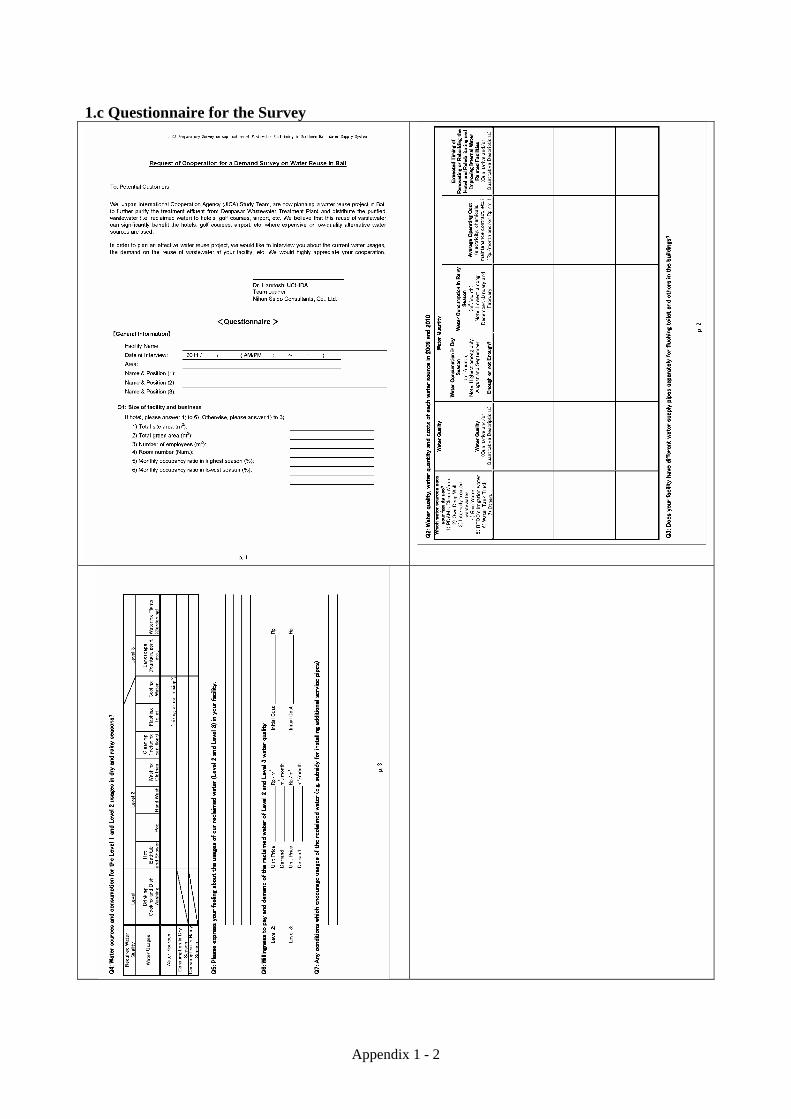
APPENDIX 1 INTERVIEW SURVEY ON THE RECLAIMED WATER USE 1.a Introduction Interview survey was executed to understand the usage and demand of reclaimed water in the southern Bali area by visiting the person in charge of the water supply and drainage facility management in a power plant, a harbor facility, large-scale hotels, golf courses, and shopping malls, etc., using the questionnaire prepared beforehand. 1.b Interview Survey Method The reclaimed water demand changes depending on the water quality and the charge. Therefore, three levels of reclaimed water quality shown below are set to understand the demand of each water quality level in the interview survey. Level 1 reclaimed water was set to ask the interviewee his image on the reclaimed water. Level 1 reclaimed water: Reclaimed water that can be used as potable water and cooking water
directly and indirectly. Level 2 reclaimed water: This is not water quality (level 1) that can be used as potable water and
cooking water. Reclaimed water that can be used without problem on water quality for other usages (shower, pool, hand wash, toilet flush, sprinkling water for landscaping pond and garden, and others.)
Level 3 reclaimed water: Reclaimed water that can be used for landscaping such as ponds and
sprinkling water for garden. There is a problem on the water quality for other usages.
The charge of reclaimed water changes greatly depending on the kind and scale of the treatment process, the scale (diameter, length and others) of the transmission facility and the scale of the pump facility. The interview survey started at the beginning of the survey, when the construction cost and O&M cost could not be calculated yet. The reclaimed water charge was not shown at the interview. Therefore, willingness to pay (unit charge) for the reclaimed water of each level was questioned. Moreover, necessity of receiving tank that is necessary when using the reclaimed water, indoor dual water supply piping (independent pipe for clear water and reclaimed water), and others were questioned. And the maximum installation cost can be borne is also questioned. In the interview survey, water source, demand by each usage, scale of water service facility, drain facility, waste water treatment plant, installation cost and O&M cost were confirmed to understand the background of the reclaimed water demand in each facility.
Appendix 1 - 2
1.c Questionnaire for the Survey
Appendix 1 - 3
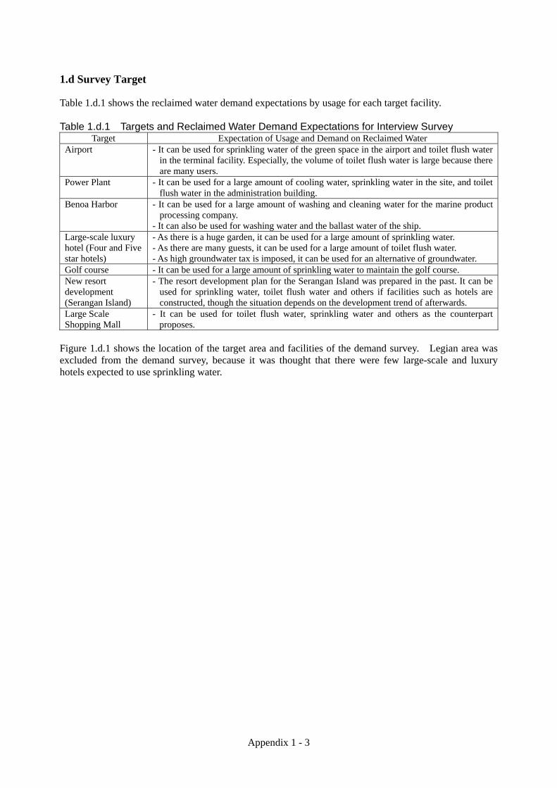
1.d Survey Target Table 1.d.1 shows the reclaimed water demand expectations by usage for each target facility. Table 1.d.1 Targets and Reclaimed Water Demand Expectations for Interview Survey
Target Expectation of Usage and Demand on Reclaimed Water Airport - It can be used for sprinkling water of the green space in the airport and toilet flush water
in the terminal facility. Especially, the volume of toilet flush water is large because there are many users.
Power Plant - It can be used for a large amount of cooling water, sprinkling water in the site, and toilet flush water in the administration building.
Benoa Harbor - It can be used for a large amount of washing and cleaning water for the marine product processing company.
- It can also be used for washing water and the ballast water of the ship. Large-scale luxury hotel (Four and Five star hotels)
- As there is a huge garden, it can be used for a large amount of sprinkling water. - As there are many guests, it can be used for a large amount of toilet flush water. - As high groundwater tax is imposed, it can be used for an alternative of groundwater.
Golf course - It can be used for a large amount of sprinkling water to maintain the golf course. New resort development (Serangan Island)
- The resort development plan for the Serangan Island was prepared in the past. It can be used for sprinkling water, toilet flush water and others if facilities such as hotels are constructed, though the situation depends on the development trend of afterwards.
Large Scale Shopping Mall
- It can be used for toilet flush water, sprinkling water and others as the counterpart proposes.
Figure 1.d.1 shows the location of the target area and facilities of the demand survey. Legian area was excluded from the demand survey, because it was thought that there were few large-scale and luxury hotels expected to use sprinkling water.

Appendix 1 - 4
Figure 1.d.1 Location of the Target Area and Facilities of the Demand Survey 1.e Result of Interview Survey As a result of the interview survey, the demand for level 1 reclaimed water was little by the sensuous reason: They do not want to use the wastewater for drinking and cooking even though it is reclaimed. Therefore, the report of the survey by the facility and area will be focused on the demand for level 2 and 3.
Power Plant
Sanur Area
Nusa Dua Area
Large Scale Shopping Mall
Ngurah Rai International Airport
Benoa Area
Benoa Harbor Serangan Island
Jimbaran Area
11 Hotels 1 Golf course
5 Hotels
BTDC Area
12 Hotels 1Golf Course
Outside of BTDC Area 2 Hotels
2 Hotels
Legian Area
Kuta Area
Denpasar WWTP
Horbor Authority 2 marine product processing companies
Note: Additionally, the reclaimed water demand for the green belt along the trunk road and park by Dinas DKP under Badung Regency was also surveyed.
5 Hotels
N

Appendix 1 - 5
(1) Power Plant (Indonesia Power) This power plant was expected as a recipient of the reclaimed water because it was located near the Denpasar WWTP where the construction of reclamation facility is examined. However, it turned out that its power generating system does not need a huge amount of the cooling water. Moreover, the treated water from the internal wastewater treatment plant is used for sprinkling water, therefore it is considered that the demand of a level 3 reclaimed water is a little. On the other hand, the interviewee answered that there is a possibility to buy the level 2 treated water if the charge is under Rp.228/m3, the groundwater tax of the power plant. However, level 2 reclaimed water demand cannot be expected under the current situation because the unit cost of current underground water is set considerably low. (2) Ngurah Rai International Airport This airport is using a small amount of PDAM water, relies on the groundwater from the internal deep well. It has a plan to expand the terminal. The plan which the groundwater is scheduled to be used as the main water source in the future is advanced now. It is at the tender stage at present, and scheduled the facility to be completed in 2013. On the other hand, there is a plan to improve the treatment facility to use the treated water as sprinkling water, toilet flushing water, and cooling water and others, though currently, the generated sewage has been discharged into the sea directly from the wastewater treatment plant after treatment. Moreover, the interviewee answered that the supply of the treated water is enough compared with the demand for the reclaimed water after the terminal is expanded. Therefore, the demand for level 2 and 3 reclaimed water is limited under the current situation. However, it is thought that there is potential as a recipient for the reclaimed water if the groundwater that is the pillar of the water supply plan becomes difficult by legal regulation, groundwater quality problem, profitability, maintenance and others in the future. It seems possible to expect as future potential recipient for the reclaimed water. (3) Benoa Harbour In the reclaimed water business prepared by Bali province government independently, Benoa Harbour is a user of the reclaimed water. But a concrete usage of the reclaimed water is not mentioned. It was expected that a large amount of reclaimed water could be used for ship cleaning, ballast water, washing water for marine product processing company and others. The demand for ship cleaning and ballast water was not made clear by the interview survey. The groundwater tax is set cheap as Rp.1,216/m3 from January 2011 though currently groundwater is used in the marine product processing company. Therefore, it is thought to be difficult to expect the level 2 and 3 reclaimed water demand under the current situation. But if the water demand for ship cleaning and ballast water is expected and/or the groundwater is difficult to use due to a regulation, the harbour would become a good recipient. (4) Golf Course There are two golf courses in the survey area. One is the Grand Bali Beach Golf Course in the Sanur area (9 holes). The other is Bali Golf and Country Club in the Nusa Dua area that is in the Bali Tourism Development Cooperation (BTDC) area where the national tourism project has been developed. Toilet flush water, shower water at clubhouse (level 2 reclaimed water) and sprinkling water (level 3 reclaimed water) in the course can be considered as the demand for reclaimed water but the level 2 reclaimed water demand cannot be expected in those golf courses because dual water supply piping system is required as well as a large amount of reclaimed water cannot be expected. Therefore, the result of the survey on

Appendix 1 - 6
level 3 is described below. In the Grand Bali Beach Golf Course in Sanur area, the treated water which is collected at the adjoining Inna Grand Bali Beach Hotel and treated at the WWTP is used for the sprinkling of the golf course. Moreover, in the worst case, if the emergency that cannot use the treated water occurs, it is possible to use the nearby river water temporarily. Therefore, the demand for level 3 reclaimed water is limited. Public sewers are developed in the Sanur area under the Sewerage Project, the sewers connections are forced by a regulation and the in-house wastewater treatment facilities are to be abandoned, then the level 3 reclaimed water demand would become high. In the Bali Golf and Country Club of Nusa Dua area, the generated sewage is treated in the WTTP of BTDC, then the treated water is purchased as reclaimed water (hereinafter referred to as BTDC irrigation water) and used for sprinkling, etc. Usually, the sprinkling water of about 500m3/d is required during the dry season. Among them, about 100m3/d is supplied from the rainwater reservoir in the golf course, about 400m3/d is supplied from the BTDC irrigation water as much as possible, and the shortfall is supplied from groundwater. According to the record of BTDC irrigation water supply amount to the golf course in the BTDC area in 2009 (Table 1.e.1), the amount of maximum reclaimed water supplied from the WWTP of BTDC to the golf course was 10,200m3/month (October, 2009), 329m3/d (converted into daily amount). From these records, level 3 reclaimed water demand becomes about 70, subtracted 100m3/d (rain water) and 329m3/d (reclaimed water of BTDC) from 500m3/d (demand for sprinkling during the dry season). The quality of BTDC irrigation water is so bad that it is used for sprinkling after mixed the BTDC irrigation water with groundwater from the deep well in another pond of the golf course. After 2009, the demand decreased to only 70m3/d because the groundwater tax rose though there is demand for the reclaimed water as an alternative water source of groundwater. Moreover, the interviewee answered that there was a possibility of purchasing more level 3 reclaimed water if it was possible to supply it by lower charge than Rp.6,812/m3, BTDC irrigation water charge. Considering the circumstances mentioned above, it was clarified that the demand of level 3 reclaimed water in the golf course is limited now, but it can be expected depending on the development of sewer connections to the public sewerage system and BTDC irrigation water supply service. (5) Large Scale Hotel 1) Sanur Area In the Sanur area, there seems to be approximately ten large-scale hotels (four or five star hotel) with many guest rooms, also large garden, and high reclaimed water demand. In this survey, the interview was done for the Bali Hyatt Hotel (five star hotel) and the Sanur Paradise Plaza Hotel (four star hotel), etc. Bali Hyatt Hotel has a waste water treatment plant, and the treated water is used as sprinkling water for the garden and landscape water for the pond. There is a plan to improve the sewage treatment enough to be used as cooling water in the future. Therefore, the demand for level 3 reclaimed water is considered as a little. Moreover, the interviewee answered that use of the level 2 reclaimed water is not assumed because a large scale construction is required to have dual water supply piping system in the building to use level 2 reclaimed water for toilet flush, etc. Therefore, the demand for the level 2 reclaimed water is depending on the establishing the dual water supply piping system. At Sanur Paradise Plaza Hotel, the level 3 demand is limited because the garden is small and the demand is only about 5m3/d even at the dry season. The demand for the level 2 reclaimed water would be limited when it is used for the toilet flush installation of new separate pipes are required but the installation work is difficult, for pool water the total water consumption is small due to circulation use

Appendix 1 - 7
and a bad image even if the reclaimed water quality is good. 2) Nusa Dua Area In the Nusa Dua area, there is BTDC service area developed as a national tourism project (hereinafter referred to as BTDC area), and there are approximately ten large-scale hotels (four or five stars). The generated sewage from these hotels is treated at the WWTP of BTDC. A part of treated water is purchased as BTDC irrigation water, and used as sprinkling water for the garden and others. At present, the influent is only around 5,000m3/d- average, and 6,000m3/d-maximum, though the design capacity of the WWTP of BTDC is 10,000m3/d. About 2,400m3/d, 40% of this treated volume at present is further treated (design capacity of the facility: 3,000m3/d) and sold as BTDC irrigation water. BTDC is now advancing the improvement program of sewage treatment facility and the reclaimed water treatment facility by BOT project, and the progress should be taken care of in the future. There are about four large-scale hotels (four or five star hotel) outside the BTDC area. Generated sewage in the hotel is treated in the internal WWTP, and the BTDC irrigation water is not used. Based on the above-mentioned situation, the result of the reclaimed water demand survey in large-scale hotels in Nusa Dua area is reported. < Large-scale hotels in BTDC area > Among large scale hotels in the BTDC area, the interview survey was done for Club Med located near the WWTP of BTDC, Ayodya Resort and Novotel Nusa Dua located far away from the WWTP, Melia Bali Villas Resort located between them, etc. It was thought that there were hotels which have the dual pipe system because the BTDC irrigation water was supplied in the BTDC area. But it was clarified that such a hotel doesn't exist through the interview with BTDC and hotels. First of all, Novotel Nusa Dua and Club Med answered that they would not break the wall and install the pipe only for the reclaimed water to supply the level 2 reclaimed water Water is leaking frequently in Ayodya Resort Hotel because 20 years has already passed since the pipe was installed in the hotel. It is necessary to examine remedial measures including the dual water supply piping in the future. There was an answer that they might examine the use of the reclaimed water depending on the level 2 reclaimed water charge. Ayodya Resort Hotel uses the groundwater of the deep well about 200m3/d at the maximum, and it is thought that it influences largely if the reclaimed water charge is cheaper than the groundwater tax when the use of the reclaimed water is examined. It is scheduled that three hotels (250 rooms at Marriott Hotel, 50 rooms at the Royal Kamuela Hotel, and 50 rooms at Laguna Villa) will be constructed by the end of 2011, and 350 rooms will increase in total in the BTDC area. In addition, the construction of three facilities (20 rooms at Villa NW-2, 200 rooms at N-5, and 5000 seats in the convention hall) is also scheduled. As the water demand will increase further in these facilities, but the present water supply capacity is not easily increase as stated in the previous section. Therefore, a promotion of the level 2 reclaimed water use by introduction of the dual water piping system in these facilities may effective use the limited water supply. As the demand for the level 3 reclaimed water, three hotels other than Ayodya Resort Hotel answered that they have enough amount of irrigation water from BTDC. As shown in Table 4.3.2, large amount of BTDC irrigation water is supplied to St. Regis Bali Resort which is located farthest away from WWTP of BTDC. New demand for the level 3 reclaimed water can hardly be expected under the present situation that there is no complain about the BTDC irrigation water supply volume and they are satisfied with

Appendix 1 - 8
BTDC irrigation water service. Ayodya Resort Hotel answered that they were using the rain water saved in the pond of the hotel about 100m3/the day for the garden during the dry season because the amount of the reclaimed water supplied from the WWTP of BTDC was not enough. It is difficult to say that the volume of the BTDC irrigation water only for Ayodya Resort Hotel is insufficient because the rain water saved in the pond in the hotel is free, and Novotel Nusa Dua Hotel receives the enough reclaimed water from BTDC. Therefore, there is high possibility of attempting the use of free rain water compared with the charged BTDC irrigation water. Considering the circumstances mentioned above, it is thought that the BTDC irrigation water supply satisfies the demand for the sprinkling water in BTDC.
Table 1.e.1 Amount of BTDC Irrigation Water Supplied to Each Facility (2009)
As mentioned above, in the BTDC area, the number of accommodation facility will increase by 350 rooms by the end of 2011, then 220 rooms afterwards, and construction of the convention hall with 5000 seats is also scheduled. These facilities will be built in BTDC where the land is originally green space. Consequently the green area will decrease and the demand of the level 3 reclaimed water in BTDC can be thought to be in the direction of decrease in the future. < Large-scale hotel outside BTDC area > The interview was done for Nikko Bali Resort and Spa where the number of guest room is the largest outside the BTDC area. This hotel uses the groundwater of the deep well. The wastewater generated in the hotel is treated at the internal wastewater treatment facility. The treated wastewater is used as sprinkling water of the garden, cooling water, and landscaping water to ponds etc. The water for these usages will be sufficient in the future, and the demand for the level 3 reclaimed water is hardly expected. In case of the level 2 reclaimed water, if all the cost for the indoor dual water supply piping work is subsidized, interviewee answered that he may purchase the level 2 reclaimed water of 20-25m3/d as pool water, 70-80m3/d as clothes washing water, and toilet flush water by around Rp.10,000/m3.
Appendix 1 - 9
The construction of three hotels (Mulia, Ritz Calton, Kedung New Wall Hotel) and one villa is scheduled outside the BTDC in Nusa Dua area in the future. It is likely that the demand for the water supply increases, but the water supply volume cannot be increased accordingly as explained in the previous section. It is thought that the need of level 2 reclaimed water use becomes high. From the above-mentioned viewpoint, the demand for the level 3 reclaimed water cannot be expected because the treated wastewater by their own wastewater treatment facility is already used for irrigation purposes, but the demand for the level 2 reclaimed water can be expected because the water demand itself will be increased but the supply volume is difficult to increase under the current waterworks supply capacity. It is thought that the level 2 reclaimed water should be used effectively to cover the gap between the water demand and supply. 3) Benoa Area The interview survey was done in the Benoa area for three large-scale hotels (Melia Benoa, Bali Tropic Resort and Spa, Conrad Bali Resort and others) located near the WWTP of BTDC. The demand for the level 2 reclaimed water may depend on the introduction of dual water supply pipe work, the same as in the case of Nusa Dua area. On the other hand, the demand for the level 3 reclaimed water is limited because of following reasons. The WWTP of BTDC accepts and treats the sewage generated at three hotels (Melia Benoa, Bali Tropic Resort and Spa, and Conrad Bali Resort) located near the WWTP but outside of BTDC area because those hotels is close to the WWTP, and provides the BTDC irrigation water to these three hotels. In the large scale hotels in Benoa area other than these three hotels, internal wastewater treatment facilities have been constructed and the treated wastewater is used for gardening. 4) Jimbaran Area There were three large-scale hotels in the Jimbaran area, and the interview survey was done for Bali Intercontinental and Four Seasons Resort. The demand for level 3 reclaimed water is limited because the irrigation water is already supplied from their own wastewater treatment facilities. But the demand for level 2 reclaimed water may be expected by installation of dual water supply system to the hotels. 5) Kuta Area In Kuta area, interview survey was done for Bali Dynasty resort, Hard Rock Hotel Bali, etc. As in the case of the large-scale hotels in other area, the demand for level 3 reclaimed water is limited because the irrigation water is already supplied from their own wastewater treatment facilities. But the demand for level 2 reclaimed water may be expected by installation of dual water supply system to the hotels. (6) Serangan Island The development of the Serangan island started in 1994. The island is expanded from 100ha to 400ha by reclamation. But the development has been interrupted with the collapse of Suharto administration in 1998. This development was advanced without building consensus with the resident. Therefore, the problem of the interest with the resident is not solved. Moreover, Bali provincial government cannot understand the trend of the Serangan island development, because the reclamation part on this island (almost vacant lot at present) was sold to the company in Singapore. In addition, there was a bridge construction project to connect Serangan island and Benoa peninsula. But there is information that the construction plan has not approved by the opposition of Benoa harbor and airport. From such a situation on the Serangan island, it is thought that it is not easy to think that the resort development will begin in the near future, and it is not in the situation that the demand for the reclaimed water can not be expected.

Appendix 1 - 10
(7) Large Scale Shopping Mall There are five large-scale shopping centers in Denpasar City and Badung Regency that was the survey area of the study. The interview survey was done for Mal Bali Galleria that was the biggest shopping mall among those shopping centers. Approximately 30m3/d as toilet flush water and 30m3/d as gardening water was expected as a target usage for the treated water in this facility. However, the willingness to pay for the level 2 reclaimed water as toilet flush water was quite low about Rp.1,000-2,000/m3. Moreover, the water source of the gardening is free river water at present. Therefore, the demand for the level 2 and 3 reclaimed water can hardly be expected because of the low water demand and the low willingness to pay. (8) Green Belt along Main Road and Park The interview survey was done for the demand of the reclaimed water as sprinkling water for the green belt along the trunk road and the park by Dinas DKP under the Badung Regency administration. Dinas DKP uses the river water for free for watering. The water from the Mati River is used as gardening water for Nusa Dua area and Kuta area. But the water is not suitable for the watering because it contains high salinity concentration. During the dry season, the volume of the water drops, and earth and sand enters. Therefore, if the reclaimed water is purchased cheaper than the groundwater tax in the Badung Regency (After the price cut), the answer they could purchase about 60m3/d (Each five round trips a day by two tank tracks (6m3)) was obtained. However, it is expected that the groundwater tax for the government agency after price cut is suppressed to low about Rp.1,000/m3. Therefore, the demand for level 3 reclaimed water may be limited due to its charge. 1

Appendix 1 - 11
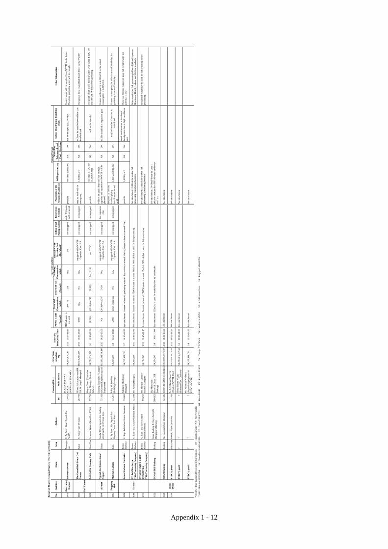
1.f Result of Water Demand Survey
Res
ult
of W
ater
Dem
and
Sur
vey
(Hot
els)
Inte
rnal
WW
TP
Op
erat
ing
Cos
t(R
p./m
3)(m
3/d
)(R
p./m
3)(m
3/d
)(R
p./m
3)P
ool
Gar
den
ing
1A
ston
Leg
end
Vil
las
Vil
la10
Jl. C
emar
a 33
San
ur27
0567
Put
u B
udia
rta
(C
hief
Eng
)N
T,D
P30
-Mar
14.0
5 –
14.4
0N
A50
0 m
3/m
onth
NA
NA
Sep
tic ta
nkno
t ins
tall
edno
sch
edul
eca
n be
con
side
red
2000
-300
0Rp/
m3
NG
OK
2B
ali H
yatt
5 st
ar38
0Jl
. Dan
au T
ambl
inga
n N
o89
San
ur P
oBox
392
2812
34M
ikae
l Yan
ei(A
sst.
Dir
ecto
r of
Eng
inee
ring
)S
K,S
M,Y
K,D
P24
-Feb
14:0
0-15
:20
8,91
6A
boli
shed
in 1
996
Abo
lishe
d in
199
6A
ve30
0,M
ax70
0eq
uipp
ed w
ith W
WT
P(6
00m
3/d)
/Cos
t: N
Ano
t ins
tall
edW
ill b
e re
nova
ted
in20
12no
t req
uire
dle
ss th
an 4
,500
Rp.
/m3
NG
OK
3G
azeb
o B
each
2 st
ar76
Jl. D
anau
Tam
blin
gan
No3
5 S
anur
2882
12Id
a B
agus
Wir
aA
dnya
na(O
pera
tion
Mgr
)N
T,D
P30
-Mar
15.5
0-16
.10
9,80
0C
apac
ity:
NA
NA
40S
epti
c ta
nkno
t ins
tall
edno
sch
edul
eca
n be
con
side
red
2000
-300
0Rp/
m3
NG
OK
4In
na
Gra
nd
Bal
i Bea
ch H
otel
5 st
ar52
3Jl
. Han
g T
uah
San
ur P
oBox
3275
2885
11N
yom
an S
ukas
ada(
Chi
efE
ng)
NT
,DP
21-M
ar13
.05-
14.1
511
,506
1800
9165
700
equi
pped
with
WW
TP
(70
0m
3/da
y) in
vest
men
t 300
mill
ionR
pno
t ins
tall
edpr
opos
al to
impr
ove
cost
est
imat
ed 3
billi
on R
p
no id
ea, b
ecau
se o
f ne
wpr
opos
al f
or W
WT
Pno
idea
NG
OK
5L
a T
avel
na
Bal
i2
star
39Jl
. Dan
au T
ambl
inga
n N
o29
San
ur28
8497
Ida
Ayu
Arm
ini(
HR
D)
Pito
no (
Ass
Chi
ef E
ng)
NT
,DP
30-M
ar16
.20-
16.4
5N
AN
AN
A9
Sep
tic
tank
not i
nsta
lled
no s
ched
ule
can
be c
onsi
dere
d20
00R
p/m
3N
GO
K
6M
ercu
re R
esor
t S
anu
r4
star
s18
9Jl
. Mer
tasa
ri S
anur
2888
33I
B S
upre
sna(
Chi
ef E
ng)
NT
,DP
30-M
ar10
.30-
11.0
56,
539
only
bac
k up
NA
70eq
uipp
ed w
ith
WW
TP
(300
m3)
not i
nsta
lled
just
bui
ld n
ew S
TP
cost
1.3
bill
ion
can
be c
onsi
dere
d20
00-3
000R
p/m
3O
KO
K
7P
uri
San
tria
n H
otel
4 st
ars
182
Jl. C
emar
a 35
San
ur P
oBox
3055
2880
09I
Way
an S
ukar
sa(C
hief
Eng
)N
T,D
P30
-Mar
11.3
5-12
.15
stan
d by
cond
itio
n33
4N
AN
AS
epti
c ta
nkno
t ins
tall
edno
sch
edul
eca
n be
con
side
red
3000
-400
0Rp/
m3
NG
OK
8S
anu
r B
each
Hot
el
5 st
ars
428
Jl. D
anau
Tam
blin
gan
San
ur P
oBox
3279
2880
11E
rwin
Lew
y R
ensu
s(C
hief
Eng
)N
T,D
P21
-Mar
14.2
5-15
.35
use
only
for
kitc
hen
1100
NA
600
equi
ppd
wit
h W
WT
P(6
00 m
3/da
y)no
t ins
tall
edne
w W
WT
Ppr
opos
al a
lrea
dydi
scus
sed
can
be c
onsi
dere
d30
00-3
500R
p/m
3O
KO
K
9S
anu
r P
arad
ise
Pla
za H
otel
4
star
s32
9Jl
. Han
g T
uah
46 S
anur
802
2828
1781
I M
ade
Sud
arsa
na(C
hief
Eng
inee
ring
)H
U,S
K,S
M,D
P18
-Feb
14:0
0-15
:50
7,95
0C
apac
ity:
NA
4,10
45
(Dry
sea
son)
not e
quip
ped
not i
nsta
lled
unde
r re
nova
tion
can
be c
onsi
dere
d3,
000R
p./m
3N
GO
K
10S
egar
a V
illa
ge4
star
s12
0Jl
. Seg
ara
Ayu
San
ur P
oBox
3091
2884
07K
adek
Ari
ana(
Chi
ef E
ng)
NT
,DP
30-M
ar13
.05-
13.4
0fo
r ba
ck u
p33
4N
AN
AS
epti
c ta
nkno
t ins
tall
edno
sch
edul
eca
n be
con
side
red
4000
-500
0Rp/
m3
NG
OK
11W
aka
May
a R
esor
tB
utiq
ueR
esor
t25
Jl. T
anju
ng P
ingg
ir P
anta
i No4
1 S
anur
2899
12K
oman
g A
gus
Suja
rwad
i (F
inan
ce-A
dm M
gr)
NT
,DP
30-M
ar15
.10-
15.4
0N
Ano
dee
p w
ell
no d
eep
wel
lN
AS
epti
c ta
nkno
t ins
tall
edno
sch
edul
eca
n be
con
side
red
4000
Rp/
m3
NG
OK
1A
man
usa
Res
ort
*)5
star
s35
Nus
a D
ua P
oBox
33
Nus
a D
ua 8
0363
7723
33I
G N
Uda
yana
(C
hief
Eng
)N
T,D
P1-
Apr
11.5
5-12
.45
use
wat
er f
rom
Bal
i Gol
fno
dee
p w
ell
no d
eep
wel
lN
Aus
e B
TD
Cno
t ins
tall
edno
sch
edul
eca
n be
con
side
red
500
0-60
00R
p/m
3O
KO
K
2A
yod
ya R
esor
t *)
5Bst
ars
451
Jala
n P
anta
i Meg
iat P
oBox
46
Nus
a D
ua 8
0363
7711
02K
etut
Wija
ya(D
irec
tor
of E
ngin
eeri
ng)
SK
,SM
,YK
,DP
1-M
ar10
:15-
11:0
012
,700
Max
200
NA
Max
100
use
BT
DC
not i
nsta
lled
no p
lan
need
s co
st c
ompa
riso
nw
ith
the
plan
ned
inte
rnal
WW
TP
NG
OK
3B
ali T
rop
ic R
esor
t4
star
s15
0Jl
. Pra
tam
a 34
A N
usa
Dua
7721
30G
usti
Lan
ang
Sw
astik
a(C
hief
Eng
)N
T,D
P18
-Mar
15.1
0-15
.55
11,3
65no
dee
p w
ell
no d
eep
wel
l75
eqqu
iped
wit
h W
WT
Pno
t ins
tall
edno
sch
edul
eca
n b
e co
side
red
no id
eaO
KO
K
4C
lub
Med
*)
4 st
ars
400
PoB
ox7
Lot
No6
Nus
a D
ua77
1521
Mic
hel N
aulo
t(T
echn
ical
Ser
vice
sM
anag
er)
SK
,SM
,TY
,YK
,DP
28-F
eb10
:00-
11:0
012
,491
no d
eep
wel
l-
Ave
60us
e B
TD
Cno
t ins
tall
edno
hot
el e
xpan
sion
plan
may
be
used
less
than
BT
DC
IW
tari
ff(6
,156
Rp.
/m3)
NG
OK
5G
ran
d H
yatt
Bal
i *)
5Bst
ars
750
PoB
ox53
Nud
a D
ua77
1234
Edw
ard
Teh
(Dir
ecto
r of
Eng
inee
ring
)S
K,N
T,S
M,D
P8-
Mar
14:0
0-15
:30
NA
no d
eep
wel
l-
NA
use
BT
DC
not i
nsta
lled
no p
lan
less
than
40c
ent
NG
NG
6In
na
Pu
tri B
ali *
)5
star
s39
2L
ot 3
-3 N
usa
Dua
PoB
ox1
Nus
a D
ua77
1020
Mad
e S
udia
rta(
Chi
ef E
ng)
NT
,DP
18-M
ar16
.10-
17.0
512
,520
no d
eep
wel
lno
dee
p w
ell
NA
use
BT
DC
not i
nsta
lled
no p
lan
can
be c
onsi
dere
d70
00R
p/m
3O
KO
K
7M
elia
Bal
i Vil
las
Res
ort
*)5B
star
s50
0L
ot N
-1 N
usa
Dua
PoB
ox88
7715
10B
inbi
n G
in W
ibow
o(C
hief
Eng
inee
ring
)H
U,S
K,S
M,Y
K,D
P25
-Feb
16:4
5-17
:00
NA
Max
240
NA
NA
use
BT
DC
not i
nsta
lled
NA
NA
NA
NA
NA
8N
ikk
o B
ali R
esor
t5B
star
s39
5Jl
. Ray
a N
usa
Dua
Sel
atan
PoB
ox18
7733
77I
WA
YA
N S
UD
IAR
SA(C
hief
Eng
inee
r)S
K,S
M,D
P23
-Feb
16:0
0-17
:00
12,5
00(2
010.
Aug
)25
2(20
10.J
ul)
6,85
6(20
10.J
ul)
NA
equi
pped
with
WW
TP
(550
m3/
d)/C
ost:
NA
not i
nsta
lled
no p
lan
may
be
used
for
fla
shin
gto
ilet,
was
hing
clo
thes
,po
olle
ss th
an 1
0,00
0Rp.
/m3
OK
OK
9N
ovot
el N
usa
Du
a B
ali *
)5
star
s26
8B
TD
C C
ompl
ex P
oBox
116
Nus
a D
ua 8
0363
8480
555
Tri
Adh
i Wir
ya A
stam
a(C
hief
Eng
inee
r)S
K,S
M,Y
K,D
P,S
S1-
Mar
14:0
0-15
:00
6,51
4-15
,122
no d
eep
wel
l-
Max
25us
e B
TD
Cno
t ins
tall
edN
AN
AN
GO
K
10N
usa
Du
a B
each
Hot
el *
)5
star
s38
1L
ot N
-4 N
usa
Dua
PoB
ox21
777
1210
Dw
i Sut
oyo(
Ass
.Chi
efE
ng)
NT
,DP
23-M
ar09
.55-
10.5
0cu
rren
t pri
ce12
0cu
rren
t pri
ceN
Aus
e B
TD
Cno
t ins
tall
edno
pla
nca
n be
con
side
red
5000
Rp/
m3
OK
OK
11N
usa
Du
a G
olf
Res
ort
*)5
star
s22
5L
ot S
W 2
BT
DC
8480
555
1-M
ar11
.45-
12.4
510
,300
1920
,000
1,00
0us
e B
TD
CN
Aca
n be
con
side
red
less
than
BT
DC
NA
OK
13S
wis
s G
ran
d B
ali *
)4
star
s63
Jl. N
usa
Dua
Sel
atan
No8
Nus
a D
ua77
6688
I W
ayan
S S
aput
ra(C
hief
Eng
)N
T,D
P1-
Apr
14.0
5-14
.55
13,7
9712
511
,380
NA
use
BT
DC
no
t ins
tall
edno
pla
nca
n be
con
side
rd40
00R
p/m
3N
GO
K
15T
he
St.
Reg
is B
ali R
esor
t *)
5 st
ars
123
Kaw
asan
Nus
a D
ua L
ot S
684
7811
1W
y W
iran
taja
(C
hief
Eng
)N
T,D
P23
-Mar
11.5
5-12
.50
12,4
9913
713
,768
NA
use
BT
DC
not i
nsta
lled
no p
lan
can
be c
onsi
red
2500
-300
0Rp/
m3
OK
OK
16T
he
Wes
tin
Res
ort
Nu
sa D
ua
*)5
star
s33
4K
awas
an B
TD
C L
ot2
Nus
a D
ua77
1906
I G
de S
omon
itaN
T,D
P23
-Mar
11.0
5-11
.45
12,5
01no
dee
p w
ell
no d
eep
wel
lN
Aus
e B
TD
Cno
t ins
tall
edno
pla
nca
n be
con
side
red
2500
Rp/
m3
OK
OK
1B
ali R
eef
Res
ort
Vil
la28
Jala
n P
rata
ma
Tan
jung
Ben
oa P
oBox
5000
7762
91M
r. D
edi S
uwec
a(E
ngin
eer)
SK
,SM
,DP
28-F
eb12
:00-
12:3
014
,908
no d
eep
wel
l-
NA
/PD
AM
wat
eris
not
use
dS
epti
c T
ank
not i
nsta
lled
NA
need
s co
nfir
mat
ion
toho
tel o
wne
rN
AN
A
2C
onra
d B
ali R
esor
t 4
star
s31
3Jl
. Pra
tam
a N
o.16
8Tj B
enoa
Nus
a D
ua77
8788
Mr.
Rai
Pus
laka
(Chi
ef E
ngin
eer)
SK
,NT
,SM
,DP
7-M
ar10
:00-
11:3
013
,740
no d
eep
wel
l-
NA
equi
pped
wit
h W
WT
P,
use
BT
DC
not i
nsta
lled
no p
lan
may
be
used
if th
e w
ater
wua
lity
is b
ette
r th
anB
TD
C-I
W.
sam
e as
BT
DC
-IW
NG
OK
3M
elia
Ben
oa B
ali
5 st
ars
128
Jl. P
rata
ma
Tan
jung
Ben
oa N
usa
Dua
7717
14W
ayan
Mar
dias
a(C
hief
Eng
)N
T,D
P23
-Mar
14.1
0-15
.45
actu
al p
rice
no d
eep
wel
lno
dee
p w
ell
NA
use
BT
DC
not i
nsta
lled
no p
lan
can
be c
onsi
dere
d35
00R
p/m
3N
GO
K
4N
ovot
el R
seso
rt B
ali B
enoa
5 st
ars
186
Jl. P
rata
ma
Tan
jung
Ben
oa P
oBox
3977
2239
Agu
s S
ubag
io(C
hief
Eng
inee
r)S
K,S
M,T
Y,Y
K,D
P28
-Feb
11:2
0-11
:45
13,0
00no
dee
p w
ell
-N
Aeq
uipp
ed w
ith W
WT
P /
Cap
acity
, Cos
t: N
Ano
t ins
tall
edN
AN
AN
AN
GO
K
5T
he
Roy
al S
antr
ian
Vil
la22
Jl. P
rata
ma
Tan
jung
Ben
oa 8
0362
7781
81M
r. W
ayan
Sub
awa
(Chi
ef E
ngin
eeri
ng)
SK
,SM
,DP
28-F
eb14
:15-
14:4
5N
AM
ax10
NA
NA
Sept
icT
ank
+ U
nder
grou
ndP
enet
ratio
nno
t ins
tall
edN
Ane
eds
conf
irm
atio
n to
hote
l ow
ner
1B
ali I
nte
rcon
tin
enta
l5B
star
s42
5Jl
. Ulu
wat
u 45
Jim
bara
n70
1888
I M
ade
Suw
inte
n(A
ssis
tant
Chi
ef E
ngin
eer)
SK
,NT
,DP
11-M
ar10
:00-
11:0
010
,113
no d
eep
wel
l-
NA
equi
pped
with
WW
TP
(600
m3/
d)/C
ost:
NA
not i
nsta
lled
no p
lan
may
be
used
for
poo
l8,
000R
p./m
3O
KO
K
2F
our
Sea
son
s R
esor
t Ji
mb
aran
5 st
ars
147
JL B
ukit
Per
mai
Jim
bara
n B
adun
g70
1010
Ida
Bag
us S
upar
dana
(Dir
of E
ng)
DP
24-M
ar14
.05-
14.5
010
,343
no d
eep
wel
lno
dee
p w
ell
7000
-80
00m
3/m
onth
equi
ped
wit
h S
TP
not i
nsta
lled
no p
lan
can
be c
onsi
dere
d30
00-4
000R
p/m
3O
KO
K
1B
ali B
inta
ng
5 st
ars
401
Jl K
arti
ka P
laza
PO
Box
106
8 K
uta
7532
88A
nang
E{P
(C
hief
Eng
)N
T,D
P29
-Mar
16.0
5-16
.30
for
back
up
only
917
7,32
3N
Aeq
uped
wit
h S
TP
not i
nsta
lled
no p
lan
can
be c
onsi
dere
d20
00-3
000R
p/m
3N
AO
K
2B
ali D
ynas
ty R
esor
t4
star
s31
2Jl
Kar
tika
Pla
za P
o B
ox 2
047
Kut
a75
2403
Dew
a Y
udia
rta(
Chi
efE
ng)
NT
,DP
29-M
ar11
.30-
12.3
5no
PD
AM
wat
er65
6ac
tual
pri
ceN
Aeq
uped
wit
h S
TP
not i
nsta
lled
no p
lan
can
be c
onsi
dere
d30
00-4
000R
p/m
3O
KO
K
3D
isco
very
Kar
tik
a P
laza
Hot
el5
star
s31
8Jl
Kar
tika
Pla
za P
O B
ox 1
012
7510
67N
ur C
ham
id(C
hief
Eng
)N
T,D
P29
-Mar
15.2
0-16
.00
only
use
for
kitc
hen
470
7,15
5N
Aeq
uipe
d w
ith
ST
Pno
t ins
tall
edno
pla
nca
n be
con
side
rd50
00-6
000/
m3
OK
OK
4H
ard
Roc
k H
otel
Bal
i4
star
s41
8Jl
Pan
tai K
uta,
Br
pand
e M
as K
uta
7618
69A
bdul
lah(
Ass
Chi
ef E
ng)
NT
,DP
1-A
pr10
.35-
11.0
5ac
tual
pri
ce30
0ac
tual
pri
ceN
Aeq
uipe
d w
ith
ST
Pno
t ins
tall
edno
pla
nca
n be
con
side
red
5000
Rp/
m3
NA
OK
5K
uta
Par
adis
o H
otel
5 st
ars
243
Jl K
arti
ka P
laza
PO
Box
113
3 K
uta
7614
14A
nang
Sur
yana
(Chi
efE
ng)
NT
,DP
29-M
ar14
.00-
15.1
0ac
tual
pri
ce50
actu
al p
rice
NA
equi
ped
wit
h S
TP
not i
nsta
lled
no p
lan
can
be c
onsi
derd
3000
Rp/
m3
OK
OK
*) B
TD
C :
Bal
i Tou
rism
Dev
elop
men
t Cor
pora
tion
IW
: Ir
riga
tion
wat
er N
A :
Not
Ava
ilab
le
**)
HU
: H
arut
oshi
UC
HID
A
S
K :
Shi
nich
iro
KA
WA
MU
RA
NT
: N
aoto
TA
KA
TO
I
S
M :
Sho
zo M
OR
I
K
F :
Kiy
oshi
FU
KU
I
T
Y :
Tok
uya
YA
ZA
WA
YK
: Y
oshi
ro K
AN
TO
DP
: K
.G.D
harm
a P
utra
SS
: S
unjo
yo S
AD
IAR
TO
Mai
n P
erso
nR
oom
sA
dd
ress
Ind
oor
Du
alP
ipin
g S
yste
m
Cu
rren
t C
ond
itio
nJI
CA
Tea
mA
tten
dan
t**
)
Inte
rvie
wD
ate(
2011
)/T
ime
Dee
p W
ell
Con
sum
pti
onG
ard
enin
gC
onsu
mp
tion
Ren
ovat
ion
Sch
edu
lete
l.
Ku
ta
No.
Ben
oaA
rea
Hot
el
San
ur
Nu
sa D
ua
Are
a
Jim
bar
an
Rat
ing
Dee
p W
ell T
axP
DA
MT
arif
f
Dem
and
Su
rvey
Wil
lin
gnes
s to
pay
Pos
sib
ilit
y of
th
ere
clai
med
wat
er u
se
Wat
er U
seT
oler
ance
Lev
el
Con
tact
s(03
61-)
Poo
lG
arde
ning
can
be c
onsi
dere
d20
00-3
000R
p/m
3N
GO
Kca
n no
t, ne
ed n
ewin
vest
men
tw
ill c
onne
ct D
SDP
not r
equi
red
less
than
4,5
00R
p./m
3N
GO
Kca
n no
t be
inst
alle
d be
caus
ela
rge
scal
e w
ork
is r
equi
red
has
som
e in
tere
st b
ut n
ot n
eces
sary
bec
ause
they
are
alre
ady
inve
stin
g in
WW
TP
can
be c
onsi
dere
d20
00-3
000R
p/m
3N
GO
Kca
n no
t, ne
ed n
ewin
vest
men
tw
ill c
onne
ct D
SDP
no id
ea, b
ecau
se o
f ne
wpr
opos
al f
or W
WT
Pno
idea
NG
OK
can
not,
need
new
inve
stm
ent
wai
ting
to c
onne
ct D
SDP
, but
the
pric
e to
hig
h
can
be c
onsi
dere
d20
00R
p/m
3N
GO
Kca
n no
t, ne
ed n
ewin
vest
men
tw
ill c
onne
ct D
SDP
can
be c
onsi
dere
d20
00-3
000R
p/m
3O
KO
Kca
n no
t, ne
ed n
ewin
vest
men
tw
ill u
se th
e w
ater
50
m3/
day
can
be c
onsi
dere
d30
00-4
000R
p/m
3N
GO
Kca
n no
t, ne
ed n
ewin
vest
men
tw
ill u
se r
ecla
imed
wat
er 5
0 m
3/da
y
can
be c
onsi
dere
d30
00-3
500R
p/m
3O
KO
Kca
n no
t be
inst
alle
d be
caus
ela
rge
scal
e w
ork
is r
equi
red
can
be c
onsi
dere
d3,
000R
p./m
3N
GO
Kw
ill n
ot b
e in
stal
led
cust
omer
aw
aren
ess
is m
ore
impo
rtan
t tha
n ho
tel
inte
ntio
n
can
be c
onsi
dere
d40
00-5
000R
p/m
3N
GO
Kca
n no
t, ne
ed n
ewin
vest
men
tw
ill u
se r
ecla
imed
wat
er 1
00 m
3/da
y
can
be c
onsi
dere
d40
00R
p/m
3N
GO
Kca
n no
tt,ne
ed n
ewin
vest
men
tw
ill u
se r
ecla
imed
wat
er 1
00 m
3/da
y
can
be c
onsi
dere
d 5
000-
6000
Rp/
m3
OK
OK
can
not,
need
new
inve
stm
ent
will
use
rec
laim
ed w
ater
50-
80m
3/da
y
need
s co
st c
ompa
riso
nw
ith
the
plan
ned
inte
rnal
WW
TP
NG
OK
depe
nds
on th
e co
stIn
stal
latio
n of
sel
f W
WT
P an
d de
salin
atio
n fa
cili
tyw
ill b
e pl
anne
d so
on.
can
be
cosi
dere
dno
idea
OK
OK
can
not,
need
new
inve
stm
ent
they
pla
n to
impr
ove
the
WW
TP
faci
lity
to g
et a
dri
nkw
ater
qua
lity
may
be
used
less
than
BT
DC
IW
tari
ff(6
,156
Rp.
/m3)
NG
OK
will
not
be
inst
alle
d un
less
new
bui
ldin
g is
con
stru
cted
BT
DC
irri
gatio
n w
ater
is n
ot u
sed
in r
ainy
sea
son
less
than
40c
ent
NG
NG
will
be
inst
alle
d if
the
cost
issu
bsid
ized
Rec
laim
ed w
ater
can
not b
e us
ed f
or g
arde
ning
beca
use
peop
le m
ay to
uch
it.
can
be c
onsi
dere
d70
00R
p/m
3O
KO
Kca
n no
t, ne
ed n
ewin
vest
men
tw
ill u
se r
ecla
imed
wat
er 3
0% o
f P
DA
M w
ater
use
s
NA
NA
NA
NA
will
not
be
inst
alle
din
terv
iew
tim
e w
as n
ot e
noug
h
may
be
used
for
fla
shin
gto
ilet,
was
hing
clo
thes
,po
olle
ss th
an 1
0,00
0Rp.
/m3
OK
OK
will
be
inst
alle
d if
the
cost
issu
bsid
ized
PDA
M w
ater
and
dee
p w
ell w
ater
are
mix
ed in
the
2,00
0m3
rece
ivin
g ta
nk
NA
NG
OK
will
not
be
inst
alle
d if
the
wal
l is
dam
aged
bette
r to
sel
l the
rec
laim
ed w
ater
via
BT
DC
can
be c
onsi
dere
d50
00R
p/m
3O
KO
Kne
ed in
vest
men
tw
ill u
se 1
00m
3/da
y
can
be c
onsi
dere
dle
ss th
an B
TD
CN
AO
Kca
n be
con
side
red
can
be c
onsi
derd
4000
Rp/
m3
NG
OK
need
inve
stm
ent
will
use
100
0m3/
mon
th
can
be c
onsi
red
2500
-300
0Rp/
m3
OK
OK
need
inve
stm
ent
if T
DS
less
than
250
0 pp
m
can
be c
onsi
dere
d25
00R
p/m
3O
KO
Kne
ed in
vest
men
tw
ill u
se 3
00 m
3/da
y
need
s co
nfir
mat
ion
toho
tel o
wne
rN
AN
Aw
ill n
ot c
onne
ct to
BT
DC
WW
TP
(E
xpen
sive
and
far
)
may
be
used
if th
e w
ater
wua
lity
is b
ette
r th
anB
TD
C-I
W.
sam
e as
BT
DC
-IW
NG
OK
may
be
inst
alle
d at
ren
ewal
peri
od a
fter
10
year
sra
inw
ater
is c
olle
cted
to u
se (
cons
umpt
ion
is N
A)
can
be c
onsi
dere
d35
00R
p/m
3N
GO
Kne
ed in
vest
men
tw
ill u
se 1
00 m
3/da
y
NA
NA
NG
OK
NA
will
not
con
nect
to B
TD
C W
WT
P (
self
WW
TP
has
nopr
oble
m)
need
s co
nfir
mat
ion
toho
tel o
wne
rw
ill n
ot c
onne
ct to
BT
DC
WW
TP
(se
lf W
WT
P is
chea
per)
may
be
used
for
poo
l8,
000R
p./m
3O
KO
Kw
ill n
ot b
e in
stal
led
low
pri
ce, c
ontin
ous
supp
ly a
nd w
ater
qua
lity
test
isre
quir
ed f
or u
se
can
be c
onsi
dere
d30
00-4
000R
p/m
3O
KO
Kne
ed in
vest
men
t
can
be c
onsi
dere
d20
00-3
000R
p/m
3N
AO
Kne
ed in
vest
men
tw
ill u
se 1
00 m
3/da
y
can
be c
onsi
dere
d30
00-4
000R
p/m
3O
KO
Kne
ed in
vest
men
tw
ill u
se 2
50 m
3/da
y
can
be c
onsi
derd
5000
-600
0/m
3O
KO
Kne
ed in
vest
men
tw
ill u
se 1
00-1
50 m
3/da
y
can
be c
onsi
dere
d50
00R
p/m
3N
AO
Kne
ed in
vest
men
tw
ill u
se 3
00 m
3/da
y
can
be c
onsi
derd
3000
Rp/
m3
OK
OK
need
inve
stm
ent
will
use
250
m3/
day
Oth
er I
nfo
rmat
ion
Ind
oor
Du
al P
ipin
gIn
stal
ltio
n W
ork
Dem
and
Su
rvey
Will
ingn
ess
to p
ayP
ossi
bili
ty o
f th
ere
clai
med
wat
er u
se
Wat
er U
seT
oler
ance
Lev
el
Appendix 1 - 12
Res
ult
of
Wat
er D
eman
d S
urv
ey (
Exc
ept
for
Hot
els)
Inte
rnal
WW
TP
Op
erat
ing
Cos
t
(Rp
./m3)
(m3/
d)
(Rp
./m3)
(m3/
d)
(Rp
./Mon
th)
Poo
lG
ard
enin
g
101
Gen
erat
ing
Sta
tion
Ind
ones
ia P
ower
Pes
angg
ara
nJl
. By
Pas
s I
Gus
ti N
gura
h R
aiN
o535
7204
21IR
.IG
AN
SU
BA
WA
PU
RT
A(M
AN
AG
ER
TE
KN
IK)
SK
,SM
,KF
,DP
2/21
15:3
0-16
:30
PD
AM
wat
er is
not u
sed
Ave
132
228
NA
NA
not e
quip
ped
unde
r F
S (
wat
erw
ill n
ot u
sed)
poss
ible
less
than
228
Rp.
/m3
NA
OK
can
inve
st u
pto
250,
000K
Rp.
102
Th
e G
ran
d B
ali B
each
Gol
fC
ours
eS
anur
Jl. H
ang
Tua
h 58
San
ur28
7733
I K
etut
Rak
a A
dnya
na (
HR
.G
A. &
Lea
gal M
anag
er)
HU
,SK
,SM
,DP
2/18
16:0
0-18
:20
8,00
0N
AN
AN
Aeq
uipp
ed w
ith W
WT
PC
apac
ity,
Cos
t: N
Ano
t equ
ippe
dno
t equ
ippe
dm
ay b
e us
ed o
nly
inem
erge
ncy
1,00
0Rp.
/m3
NA
OK
will
not
be
inst
alle
d ev
en if
the
cost
is s
ubsi
dize
d
103
Bal
i Gol
f &
Cou
ntr
y C
ulb
Nus
a D
uaK
awas
an W
isat
a N
usa
Dua
803
6377
1791
Way
an N
awa
(Exe
cutiv
eA
sst.
Man
ager
Gen
eral
Aff
airs
)S
K,S
M,Y
K,D
P3/
116
:00-
18:2
010
,300
(201
0)A
ve23
320
,000
Max
1,10
0us
e B
TD
Cno
t equ
ippe
dno
t equ
ippe
dpo
ssib
lele
ss th
an B
TD
C-I
W(5
,200
Rp.
/m3)
NG
OK
wil
l not
be
inst
alle
d
104
Air
por
tN
gura
h R
ai I
nte
rnat
ion
arl
Air
por
tT
uban
Ban
dar
Uda
ra N
gura
h R
ai G
edun
gW
isti
Sab
ha L
t.3 T
uban
Kut
a75
1011
Gun
ung
Ban
endr
o (M
anag
erof
Gen
eral
Eng
inee
ring
and
Equ
ipm
ent)
HU
,SK
,SM
,YK
,DP
2/25
14:2
0-15
:00
NA
(201
0)A
ve2,
247
7,43
4N
Aeq
uipp
ed w
ith W
WT
PC
apac
ity,
Cos
t: N
Ano
t equ
ippe
dha
s ex
pans
ion
plan
NA
OK
will
be
inst
alle
d at
exp
ansi
on p
art
105
Sh
opp
ing
Mal
lM
al B
ali G
alle
ria
Kut
aJl
. By
Pas
s I
Gst
. Ngu
rah
Rai
Sim
pang
Dew
a R
uci K
uta
7552
77Je
ffry
M. L
omba
n(B
uild
ing
Man
ger)
SK
,SM
,DP
3/9
15:5
0-16
:15
5,00
0no
t in
oper
atio
nN
AN
Aeq
uipp
ed w
ith W
WT
PC
apac
ity,
Cos
t: N
Ano
t equ
ippe
dno
t equ
ippe
d
Dep
ends
on
the
cost
for
dual
pip
ing
inst
allt
ion
wor
k an
dta
riff
1,00
0-2,
000R
p./m
3N
AO
Km
ay b
e in
stal
led
if th
e co
st is
subs
idiz
ed
109
Ben
oa H
arb
our
Au
thor
ity
Ben
oaH
arbo
urJl
. Ray
a P
elab
uhan
Ben
oa D
enpa
sar
7205
60Ju
diha
rto
(Tec
hnic
alM
anag
er)
SK
,NT
,SM
,DP
3/7
14:0
0-16
:20
poss
ible
3,00
0Rp.
/m3
NA
OK
need
s co
nfir
mat
ion
to S
urab
aya
head
quar
ter
due
to h
igh
inst
alla
tion
cost
110
PT
. In
ti M
as S
ury
a(F
ish
Pro
cess
ing
Com
pan
y)B
enoa
Har
bour
Jl. I
kan
Tun
a B
arat
Pel
abuh
an B
enoa
7242
46M
r. A
min
(Man
ager
)S
K,S
M,D
P3/
1010
:00-
10:3
0
111
PT
.SA
RI
SE
GE
R L
AU
TIN
DO
NE
SIA
(Fis
h P
roce
ssin
g C
omp
any)
Ben
oaH
arbo
urJl
. Ika
n T
una
Ray
a T
imur
1P
elab
uhan
Ben
oa77
0233
Mr.
Mar
uko
(Dir
ecto
rF
acto
ry M
anag
er)
SK
,SM
,DP
3/10
10:4
5-11
:15
112
DIN
AS
DK
P B
adu
ng
Bad
ung
Pus
en B
adun
g Jl
. Ray
a S
empi
diM
angu
pura
Bad
ung
9004
263
Eka
Mer
taw
an(H
ead
of D
inas
DK
PB
adun
g)S
K,S
M,D
P3/
810
:0-1
1:00
113
PD
AM
Bad
un
gB
adun
gJl
n. B
edah
ulu
No3
Den
pasa
r42
1845
KO
MA
RU
DIN
,ST
(DIR
TE
K)
HU
,SK
,SM
,KF
,TY
,DP
2/22
14:0
0-15
:30
See
att
achm
ent
114
BT
DC
*) p
art1
Nus
a D
uaP
oBox
3 N
usa
Dua
8036
377
1010
A. A
. I. R
atna
Dew
i, S
t (
Hea
d of
WW
TP
Uni
t)H
U,S
K,S
M,K
F,T
Y,D
P2/
2209
:15-
11:2
0S
ee a
ttac
hmen
t
BT
DC
*) p
art2
↑↑
↑I
Put
u T
risn
a W
ijay
a(B
usin
ess
Dev
. Div
isio
n)SK
,SM
,YK
,DP
,SS
3/2
09:0
0-11
:00
See
att
achm
ent
BT
DC
*) p
art3
↑↑
↑
Mr.
Nyo
man
Wed
astr
a(S
uper
visi
ng O
pera
tor
ofB
TD
C’s
WW
TP
)S
K,N
T,S
M,D
P3/
815
:30-
14:3
0S
ee a
ttac
hmen
t
*) B
TD
C :
Bal
i Tou
rism
Dev
elop
men
t Cor
pora
tion
IW
: Ir
riga
tion
wat
er N
A :
Not
Ava
ilab
le
**)
HU
: H
arut
oshi
UC
HID
A
S
K :
Shi
nich
iro
KA
WA
MU
RA
NT
: N
aoto
TA
KA
TO
I
S
M :
Sho
zo M
OR
I
K
F :
Kiy
oshi
FU
KU
I
T
Y :
Tok
uya
YA
ZA
WA
YK
: Y
oshi
ro K
AN
TO
DP
: K
.G.D
harm
a P
utra
SS
: S
unjo
yo S
AD
IAR
TO
Cu
rren
t C
ond
itio
n
Pos
sib
ility
of
the
recl
aim
ed w
ater
use
Wil
lin
gnes
s to
pay
Wat
er U
seT
oler
ance
Lev
elD
eep
Wel
lC
onsu
mp
tion
PD
AM
Tar
iff
Ren
ovat
ion
Sch
edu
leD
eep
Wel
l Tax
Gar
den
ing
Con
sum
pti
onIn
doo
r D
ual
Pip
ing
Sys
tem
Ind
oor
Du
al P
ipin
g I
nst
allt
ion
Wor
k
Dem
and
Su
rvey
See
att
achm
ent
See
att
achm
ent:
135
m3/
d is
use
d fo
r ro
adsi
de p
lant
by
tank
truc
ks.
See
att
achm
ent
See
att
achm
ent
See
att
achm
ent
See
att
achm
ent:
Cur
rent
vol
ume
of P
DA
M w
ater
is a
roun
d 39
m3/
d. 9
0% o
f th
at is
use
d fo
r fi
sh p
roce
ssin
g.S
ee a
ttac
hmen
t: D
iffi
cult
to u
se f
or f
ish
proc
essi
ng c
onsi
deri
ng b
ecte
ria
No.
Har
bou
r
Pub
lic
Off
ice
Fac
ilit
ies
Gol
f C
ours
e
Ad
dre
ssIn
terv
iew
Dat
e(20
11)/
Tim
eN
ame
Are
aC
onta
cts(
0361
-)
tel.
Mai
n P
erso
n
JIC
A T
eam
Att
end
ant
**)
See
att
achm
ent:
54-
60m
3/d
may
be
used
ifpr
ice
is c
heap
er th
an P
DA
M w
ater
and
dee
pw
ell t
ax
wil
l not
be
used
(de
ep w
ell h
as e
noug
hca
paci
ty a
nd e
xpan
sion
of
WW
TP
wil
l be
plan
ned)
See
att
achm
ent:
Dif
ficu
lt to
use
for
fis
hpr
oces
sing
con
side
ring
bec
teri
a
See
att
achm
ent:
Cur
rent
vol
ume
of g
arde
ning
wat
er in
dry
sea
son
is a
roun
d 20
m3 /d
, fut
ure
volu
me
is a
roun
d 75
m3 .
See
att
achm
ent:
Cur
rent
vol
ume
of P
DA
M w
ater
is a
roun
d 66
m3/
d. 9
0% o
f th
at is
use
d fo
r fi
sh p
roce
ssin
g.
Poo
lG
ard
enin
g
poss
ible
less
than
228
Rp.
/m3
NA
OK
can
inve
st u
pto
250,
000K
Rp.
Tre
ated
wat
er w
ill b
e su
pplie
d fr
om W
WT
P in
the
futu
re.
The
refo
re g
arde
ning
wat
er w
ill b
e en
ough
.
may
be
used
onl
y in
emer
genc
y1,
000R
p./m
3N
AO
Kw
ill n
ot b
e in
stal
led
even
if th
e co
stis
sub
sidi
zed
Our
gro
up, I
nna
Gra
nd B
ali B
each
Hot
el o
wns
WW
TP
.
poss
ible
less
than
BT
DC
-IW
(5,2
00R
p./m
3)N
GO
Kw
ill n
ot b
e in
stal
led
The
pon
d w
hich
sto
res
the
rain
wat
er, w
ell w
ater
, BT
DC
-IW
and
PD
AM
-IW
is u
sed
for
gard
enin
g.
NA
OK
wil
l be
inst
alle
d at
exp
ansi
on p
art
Cur
rent
wel
l cap
acit
y is
4,2
00m
3/d,
whi
le a
ctua
lco
nsum
ptio
n is
2,2
47m
3/d.
Dep
ends
on
the
cost
for
dual
pip
ing
inst
allt
ion
wor
k an
dta
riff
1,00
0-2,
000R
p./m
3N
AO
Km
ay b
e in
stal
led
if th
e co
st is
subs
idiz
edC
urre
nt c
onsu
mpt
ion
for
toil
et is
aro
und
30m
3/da
y, f
orga
rden
ing
is a
roun
d 30
m3/
day.
poss
ible
3,00
0Rp.
/m3
NA
OK
need
s co
nfir
mat
ion
to S
urab
aya
head
quar
ter
due
to h
igh
inst
alla
tion
cost
The
re is
a h
arbo
ur e
xpan
sion
pla
n, b
ut r
ecla
im w
ater
use
pote
ntia
l is
low
.
Wat
er q
ualit
y fo
r fi
sh p
roce
ssin
g fo
llow
s IS
O a
nd J
apan
ese
Min
iste
r of
Hea
lth,
Lab
our
and
Wel
fare
sta
ndar
ds
Rec
laim
ed w
ater
may
be
used
for
fis
h w
ashi
ng b
efor
epr
oces
sing
See
atta
chm
ent
See
atta
chm
ent
See
atta
chm
ent
See
atta
chm
ent
Pos
sib
ilit
y of
th
ere
clai
med
wat
er u
seW
illi
ngn
ess
to p
ayW
ater
Use
Tol
eran
ce L
evel
Ind
oor
Du
al P
ipin
g I
nst
allt
ion
Wor
kO
ther
In
form
atio
n
Dem
and
Su
rvey
See
att
achm
ent:
Dif
ficu
lt to
use
for
fis
hpr
oces
sing
con
side
ring
bec
teri
a
See
att
achm
ent:
54-6
0m3/
d m
ay b
e us
ed if
pric
e is
che
aper
than
PD
AM
wat
er a
nd d
eep
wel
l tax
will
not
be
used
(de
ep w
ell h
as e
noug
hca
paci
ty a
nd e
xpan
sion
of
WW
TP
will
be
plan
ned)
See
att
achm
ent:
Dif
ficu
lt to
use
for
fis
hpr
oces
sing
con
side
ring
bec
teri
a

APPENDIX 2
WATER QUALITY SURVEY

Appendix 2 - 1
APPENDIX 2 WATER QUALITY SURVEY 2.a Terms of Reference Water quality survey was carried out to prepare the material to understand the characteristics of the effluent of Denpasar WWTP which is the raw water, and to determine the treatment process which is required for the reclaimed water treatment facility. The contents of the survey are shown below.
Outline of the Water Quality Survey Item Contents
1. Sampling Location Influent and Effluent of Denpasar WWTP
2. Sample Number 1 sample x 4 events x 2 locations = 8
3. Parameters
Influent: 7 parameters
pH, Water Temp, COD, BOD5, SS, Total Nitrogen (T-N), Total Phosphorus (T-P)
Effluent: 16 parameters
pH, Water Temp, COD, BOD5, SS, UV254, Turbidity, Color, Cl-, CO3
2-, KMO4, Total Nitrogen (T-N), NH4+-N, NO2-N, NO3-N,
Total Phosphorus (T-P)

Appendix 2 - 2
Terms of Reference

Appendix 2 - 3
2.b Survey Photo 2nd sampling on 18th May
3rd sampling on 26th May
4th sampling on 1st June

Appendix 2 - 4
2.c Survey Result

Appendix 2 - 5

Appendix 2 - 6

APPENDIX 3
TOPOGRAPHIC SURVEY

Appendix 3 - 1
APPENDIX 3 TOPOGRAPHIC SURVEY 3.a Terms of Reference Transmission pipe route was selected and the line survey with the following specifications was carried out.
Total Length: about 16km with the width of about 25m Scale of Plan: 1/500 Scale of Longitudinal Section: H=1/500, V=1/100 Scale of Cross Section: 1/100

Appendix 3 - 2
Terms of Reference
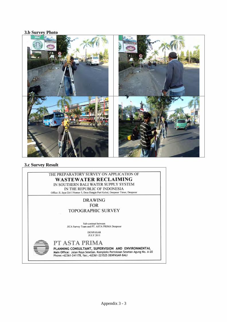
Appendix 3 - 3
3.b Survey Photo
3.c Survey Result

Appendix 3 - 4

Appendix 3 - 5

Appendix 3 - 6

Appendix 3 - 7
Appendix 3 - 8

Appendix 3 - 9

Appendix 3 - 10

Appendix 3 - 11

Appendix 3 - 12

Appendix 3 - 13

Appendix 3 - 14

Appendix 3 - 15

Appendix 3 - 16

Appendix 3 - 17

Appendix 3 - 18

Appendix 3 - 19

Appendix 3 - 20

Appendix 3 - 21

APPENDIX 4
GEOTECHNICAL SURVEY

Appendix 4 - 1
APPENDIX 4 GEOTECHNICAL SURVEY 4.a Terms of Reference Geotechnical survey for the construction site of the reclaimed water treatment plant (located at the Denpasar WWTP expansion site) was carried out with the following specifications.
Specifications of Geotechnical Survey
Item Specification Number of boring 3 Maximum depth 40m Total depth 120m
Test item and sampling number is shown below
Test Item and Sampling Number
Item Specification 1. Standard penetration test Every 1.0m interval 2. Sampling Every 10 meters interval and the bottom 3. Laboratory Test 1) Specific gravity 2) Water content 3) Particle size distribution 4) Unconfined compressive strength

Appendix 4 - 2
Terms of Reference

Appendix 4 - 3

Appendix 4 - 4
4.b Survey Photo

Appendix 4 - 5

Appendix 4 - 6

Appendix 4 - 7

Appendix 4 - 8

Appendix 4 - 9

Appendix 4 - 10
4.c Survey Result

Appendix 4 - 11
BOREHOLE LOGS

Appendix 4 - 12

Appendix 4 - 13
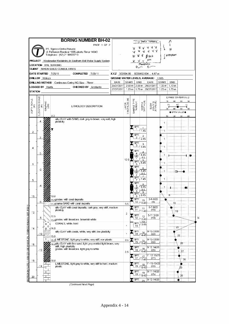
Appendix 4 - 14

Appendix 4 - 15

Appendix 4 - 16

Appendix 4 - 17

Appendix 4 - 18

Appendix 4 - 19

Appendix 4 - 20
LAB TEST RESULTS
Specific Gravity Test Moisture Content Test Density Test Sieve Analysis Hydrometer Analysis Unconfined Compression Test Atterberg Limits

Appendix 4 - 21
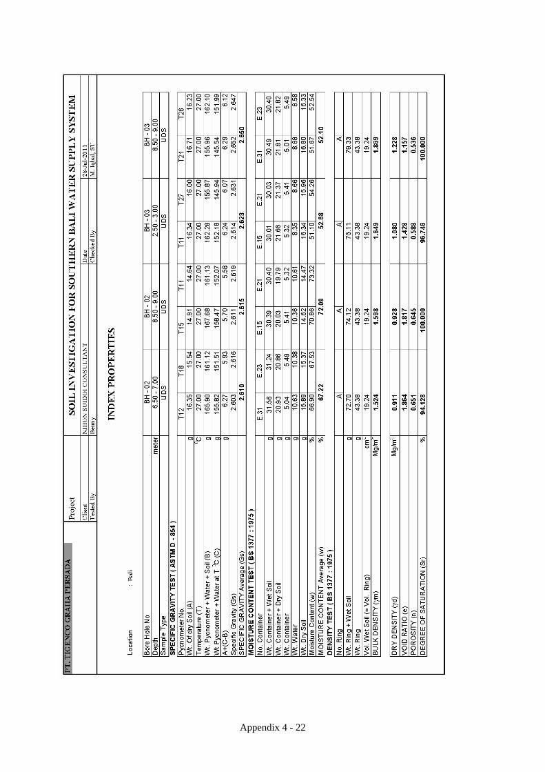
Appendix 4 - 22

Appendix 4 - 23

Appendix 4 - 24

Appendix 4 - 25

Appendix 4 - 26

Appendix 4 - 27

Appendix 4 - 28

Appendix 4 - 29

Appendix 4 - 30

Appendix 4 - 31

Appendix 4 - 32

Appendix 4 - 33

Appendix 4 - 34

Appendix 4 - 35

Appendix 4 - 36

Appendix 4 - 37

Appendix 4 - 38

Appendix 4 - 39

Appendix 4 - 40

Appendix 4 - 41

Appendix 4 - 42

Appendix 4 - 43

Appendix 4 - 44

Appendix 4 - 45

Appendix 4 - 46

Appendix 4 - 47

Appendix 4 - 48

Appendix 4 - 49

Appendix 4 - 50

Appendix 4 - 51

Appendix 4 - 52

Appendix 4 - 53

Appendix 4 - 54

Appendix 4 - 55

Appendix 4 - 56

Appendix 4 - 57

Appendix 4 - 58

Appendix 4 - 59

Appendix 4 - 60

Appendix 4 - 61

Appendix 4 - 62

Appendix 4 - 63

Appendix 4 - 64

Appendix 4 - 65

Appendix 4 - 66

Appendix 4 - 67

Appendix 4 - 68

Appendix 4 - 69
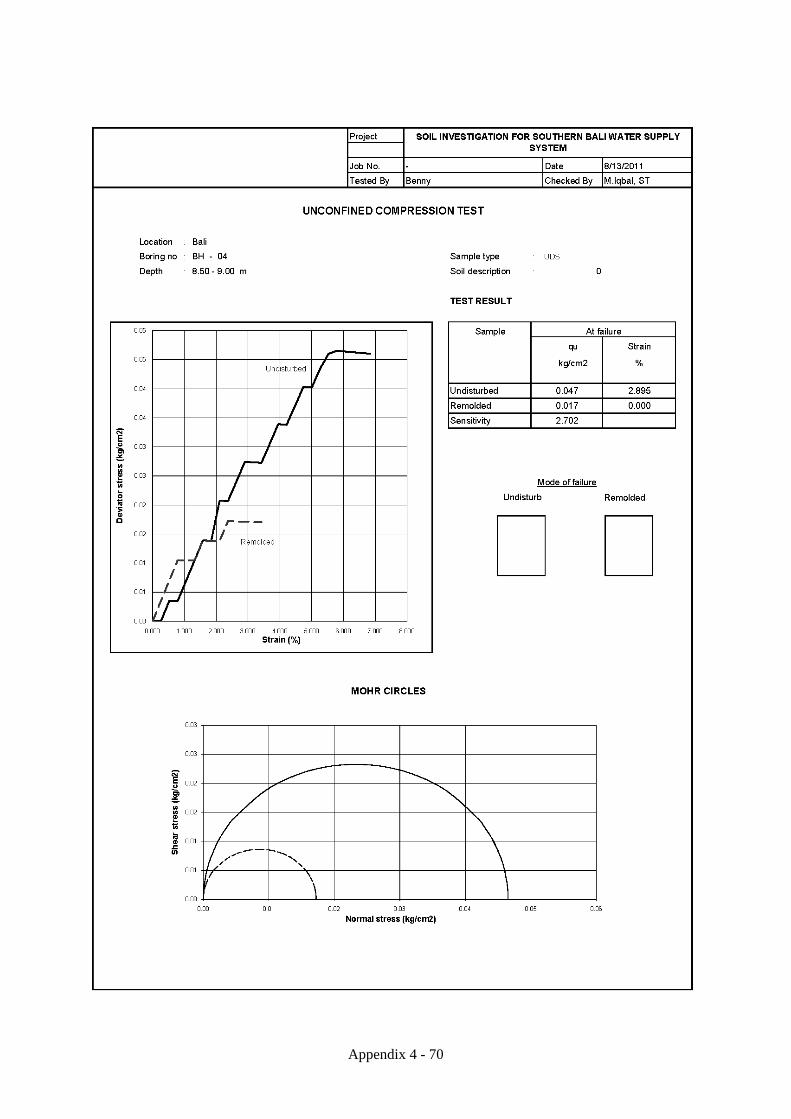
Appendix 4 - 70

Appendix 4 - 71

Appendix 4 - 72
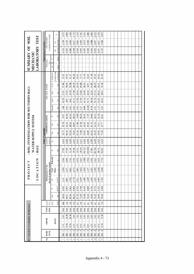
Appendix 4 - 73

Appendix 4 - 74

Appendix 4 - 75

Appendix 4 - 76

Appendix 4 - 77

Appendix 4 - 78

Appendix 4 - 79

Appendix 4 - 80

Appendix 4 - 81

Appendix 4 - 82

Appendix 4 - 83

Appendix 4 - 84

Appendix 4 - 85

Appendix 4 - 86
BEARING CAPACITY

Appendix 4 - 87

Appendix 4 - 88

Appendix 4 - 89

Appendix 4 - 90

Appendix 4 - 91

Appendix 4 - 92

Appendix 4 - 93
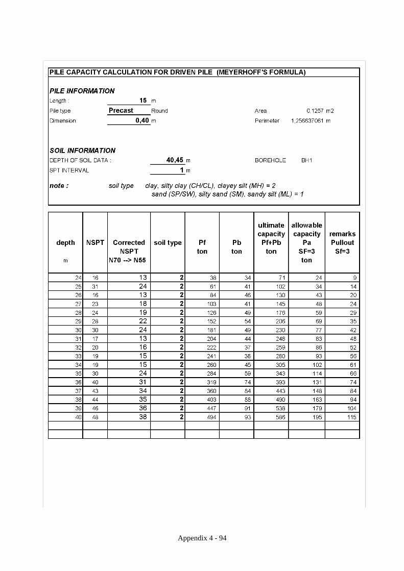
Appendix 4 - 94

Appendix 4 - 95

Appendix 4 - 96

Appendix 4 - 97

Appendix 4 - 98

Appendix 4 - 99

Appendix 4 - 100

Appendix 4 - 101

Appendix 4 - 102

Appendix 4 - 103

Appendix 4 - 104

Appendix 4 - 105

Appendix 4 - 106

Appendix 4 - 107
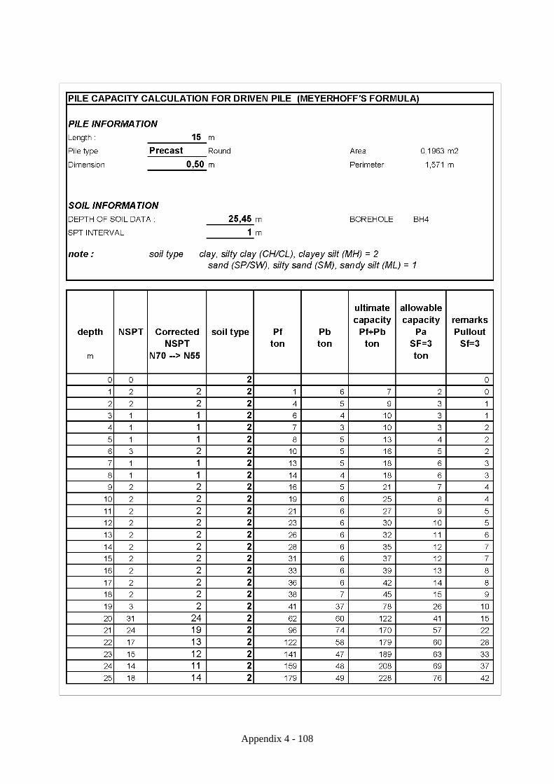
Appendix 4 - 108

Appendix 4 - 109
SHALLOW BEARING

Appendix 4 - 110
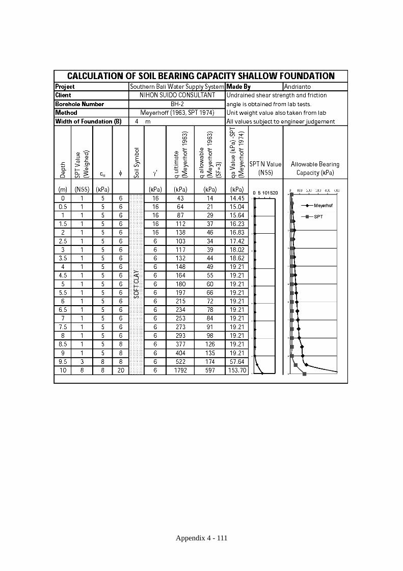
Appendix 4 - 111

Appendix 4 - 112

Appendix 4 - 113

APPENDIX 5
CONCEPT DESIGN OF RECLAIMED
WATER TREATMENT FACILITY

APPENDIX 5 CONCEPT DESIGN OF RECLAIMED WATER TREATMENT FACILITY
5.a Calculation Sheets Water Reclaimed Water for BALIItem Case 1 Case 2
1.Design Parameter1-1 Outline of Reclaimed Water System(1) Area of Plant(2) Grand Level of Plant(3) Type of Reclaimed Water System(4) Water Treatment Process
1-2 Design Flowrate Water Reuse Maximum Daily Flowrate 4500m3/d 9000m3/dReclaimed Water System FlowrateRaw Water Flowrate 5900m3/d 11800m3/dBiological Filtration Flowrate 5900m3/d 11800m3/dOzone Cotactor Flowrate 4800m3/d 9600m3/dCeramic Membrane Filtration Flowrate 4800m3/d 9600m3/dReclaimed Water Flowrate 4800m3/d 9600m3/d
1-3 Number of Series 1 Series 2 Series
2.Raw Water2-1 Raw Water Tank Raw Water Flowrate = 5900m3/d = 11800m3/d
Retention Time = 5.0 minutes = 5.0 minutes
Req. Volume = 5900m3/d / 1440min/d = 11800m3/d / 1440min/d x 5min ≒20.5m3 x 5min ≒41m3
Number of Series = 1 Series = 2 Series
Number of Basin = 1 Basin = 1 Basin
One Basin Volume = 20.5 / 1 = 20.5m 3 = 41 / 2 / 1 = 20.5m 3
Length = 3.3 m = 3.3 m
Width = 2.5 m = 2.5 m
Water Depth = 2.5 m = 2.5 m
Total Volume = 3.3 x 2.5 x 2.5 = 3.3 x 2.5 x 2.5
= 20.625 m3/Series = 20.625 m3/Series
Total Number of Basins = 2 Basins = 2 Basins
Raw Water Feed Pump Total Pump Capacity = 5900m3/d / 1440min/d = 11800m3/d / 1440min/d
≒ 4.1m3/min ≒ 8.2m3/min
Number of Series = 1 Series = 2 Series
Pump Capacity = 4.1 / 12 = 4.1m 3/min = 8.2 / 2 = 4.1m 3/min
Total Number of Pumps = 2 Pumps = 3 Pumps (Including Backup Pump) (Including Backup Pump)
Appendix 5 - 1

Item Case 1 Case 23.Biological Filtration 3-1 Biological Filtration Tank Design Flowrate Biological Filtration Flowrate = 5900m3/d = 11800m3/d
Biological Filtration Speed = 40m/d = 40m/d
Req. Area = 5900m3/d / 40m/d = 11800m3/d / 40m/d = 148m2 = 295m2
Number of Series = 1 Series = 2 Series
Number of Basin = 4 Basins = 4 Basins
One Reactor Req. Area = 148 / 1 / 4 = 37m 2 = 295 / 2 / 4 = 36.9m 2
Length = 6.1 m = 6.1 m
Width = 6.1 m = 6.1 m
Biological Filtration Area = 6.1 x 6.1 = 37.21m 2 = 6.1 x 6.1 = 37.21m 2
Total Number of Basins = 4 Basins = 8 Basins
Biological Filtration Backwash Pump Biological Filtration Area = 37.21m2 = 37.21m2
Backwash Speed = 0.45m3/m2・min = 0.45m3/m2
・min
Pump Capacity = 37.21 X 0.45 = 37.21 X 0.45
≒ 16.8m3/min ≒ 16.8m3/min
Number of Series = 1 Series = 2 Series
Req. Number of Pump / One Series = 1 Pump = 1 Pump
Total Number of Pumps = 2 Pumps = 3 Pumps (Including Backup Pump) (Including Backup Pump)
Appendix 5 - 2

Item Case 1 Case 23-2 Biological Filter Treated Water Tank Biological Filtration Flowrate = 5900m3/d = 11800m3/d
Ozone Cotactor Flowrate = 4800m3/d = 9600m3/d
Biological Filtration Backwash Water = 5900m3 - 4800m3 = 11800m3 - 9600m3
= 1100m3 = 2200m3
Number of Series = 1 Series = 2 Series
Number of Basin = 4 Basins = 4 Basins
One Cotactor Req. Backwash Water = 1100 / 1 / 4 = 2200 / 2 / 4
= 275m3 = 275m3
Retention Time of Biological Filter Backwash = 30.0 minutes = 30.0 minutes
Outflow of Biological Filter Treated Water Tank = 3.4m3/min = 3.4m3/min
Inflow of Biological Filter Treated Water Tank = 4.1m3/min = 4.1m3/min
One Cotactor Req. Volume = 275 + 3.4 x 30 = 275 + 3.4 x 30 - 4.1 x 30 = 254m 3 - 4.1 x 30 = 254m 3
Length = 15.0 m = 15.0 m
Width = 6.3 m = 6.3 m
Water Depth = 3.3 m = 3.3 m
Total Volume = 15.0 x 6.3 x 3.3 = 15.0 x 6.3 x 3.3
≒ 311.8m3 ≒ 311.8m3
Total Number of Basin = 1 Basin = 1 Basin
Biological Filter Treated Water Feed Pump Ozone Cotactor Flowrate = 4800m3/d = 9600m3/d
Total Pump Capacity = 4800m3/d / 1440min/d = 9600m3/d / 1440min/d ≒ 3.4m3/min ≒ 6.8m3/min
Number of Series = 1 Series = 2 Series
Pump Capacity = 3.4 / 1 = 3.4m 3/min = 6.8 / 2 = 3.4m 3/min
Total Number of Pumps = 2pumps = 3pumps (Including Backup Pump) (Including Backup Pump)
Appendix 5 - 3

Item Case 1 Case 24.Ozone Cotactor4-1 Ozone Cotactor Tank Ozone Cotactor Flowrate = 4800m3/d = 9600m3/d
Retention Time = 5.0 minutes = 5.0 minutes
Req. Volume = 4800m3/d / 1440min/d = 9600m3/d / 1440min/d x 5min ≒16.7m3 x 5min ≒33.4m3
Number of Series = 1 Series = 2 Series
Number of Basin (2 Basins in Series) = 1 Basin = 1 Basin
One Reactor Volume = 16.7 / 1 / 1 = 16.7m 3 = 33.4 / 2 / 1 = 16.7m 3
Length = 2.9 m = 2.9 m
Width = 1.3 m = 1.3 m
Water Depth = 5.0 m = 5.0 m
Total Volume = 2.9 x 1.3 x 5.0 = 2.9 x 1.3 x 5.0
= 18.8m3/Basin = 18.8m3/Basin
Total Number of Basins = 1 Basin = 2 Basins
Appendix 5 - 4

Item Case 1 Case 24-2 Coagulation / Flocculation Tank Coagulation Tank Ozone Cotactor Flowrate = 4800m3/d = 9600m3/d
Retention Time of Congulation Tank = 1.0 minutes = 1.0 minutes
Req. Volume of Congulation Tank = 4800m3/d / 1440min/d = 9600m3/d / 1440min/d x 1min ≒ 3.4m3 x 1min ≒ 6.8m3
Number of Series = 1 Series = 2 Series
Number of Basin = 1 Basin = 1 Basin
One Reactor Volume = 3.4 / 1 / 1 = 3.4m 3 = 6.8 / 2 / 1 = 3.4m 3
Length = 1.5 m = 1.5 m
Width = 2.0 m = 2.0 m
Water Depth = 1.7 m = 1.7 m
Total Volume = 1.5 x 2.0 x 1.7 = 5.1m 3 = 1.5 x 2.0 x 1.7 = 5.1m 3
Flocculation Tank Retention Time of Flocculation Tank = 2.0 minutes = 2.0 minutes
Req. Volume of Congulation Tank = 4800m3/d / 1440min/d = 9600m3/d / 1440min/d x 2min ≒ 6.7m3 x 2min ≒ 13.4m3
Number of Series = 1 Series = 2 Series
Number of Basin (2 Basins in Series) = 1 Basin = 1 Basin
One Reactor Volume = 6.7 / 1 / 1 = 6.7m 3 = 13.4 / 2 / 1 = 6.7m 3
Length = 2.0 m = 2.0 m
Width = 2.0 m = 2.0 m
Water Depth = 1.7 m = 1.7 m
Total Volume = 2.0 x 2.0 x 1.7 = 6.8m 3 = 2.0 x 2.0 x 1.7 = 6.8m 3
Total Number of Basins = 1 Basin = 2 Basins (Coagulation / Flocculation Tank)
Coagulated / Flocculated Water Feed Pump Total Pump Capacity = 4800m3/d ≒ 6.8m3/min = 9600m3/d ≒ 6.8m3/min
Number of Series = 1 Series = 2 Series
Pump Capacity = 3.4 / 1 = 3.4m 3/min = 6.8 / 2 = 3.4m 3/min
Pump Numbers = 2pumps = 3pumps (Including Backup Pump) (Including Backup Pump)
Appendix 5 - 5

Item Case 1 Case 25.Ceramic Membrane Filtration Unit Ceramic Membrane Filtration Flowrate = 4800m3/d = 9600m3/d
Design One Ceramic Membrane Filter Area = 25m2 = 25m2
Design Velocity = 4.0m3/m2/d = 4.0m3/m2/d
Efficiency = 0.9 = 0.9
Req. Number of Ceramic Membrane Filters = 4800m3/d / 25m2 = 9600m3/d / 25m2
/ 4.0m3/m2/d / 0.9≒53.4 / 4.0m3/m2/d / 0.9≒106.7
Design Module of Ceramic Membrane Filters = 10 Filters = 10 Filters
Design Series of Modules = 6 Modules = 6 Modules
Number of Series = 1 Series = 2 Series
Design Number of Ceramic Membrane Filters = 10 x 6 x 1 = 60 Filters = 10 x 6 x 2 = 120 Filters
6.Reclaimed Water Tank Reclaimed Water Flowrate = 4800m3/d = 9600m3/d
Retention Time of Congulation Tank = 5.0 minutes = 5.0 minutes
Req. Volume = 4800m3/d / 1440min/d = 9600m3/d / 1440min/d x 5min ≒ 16.7m3 x 5min ≒ 33.3m3
Number of Basin = 1 Basin = 1 Basin
One Basin Volume = 16.7 / 1 = 16.7m 3 = 33.3 / 1 = 33.3m 3
Length = 8.1 m = 8.1 m
Width = 3.8 m = 3.8 m
Water Depth = 2.0 m = 2.0 m
Total Volume = 8.1 x 3.8 x 2.0 = 8.1 x 3.8 x 2.0
= 61.5 m3/System = 61.5 m3/System
Total Number of Basin = 1 Basin = 1 Basin
Appendix 5 - 6

Appendix5 - 7
5.b Design Drawing G
ener
al
La
yo
ut

Appendix5 - 8

Appendix5 - 9

Appendix5 - 10

Appendix5 - 11

Appendix5 - 12

Appendix5 - 13

Appendix5 - 14

Appendix5 - 15

Appendix5 - 16
APPENDIX 6
CONCEPT DESIGN OF
TRANSMISSION FACILITY

Appendix 6 -1
APPENDIX 6 CONCEPT DESIGN OF TRANSMISSION FACILITY 6.a Design Criteria The following descriptions are shown for the case of Case2. 6.a.1 Transmission pump facility Design Transmission Flow: Maximum daily flow shall be considered for the transmission pump.
Design maximum daily flow 9,000 m3/day (= 6.250 m3/min = 104.2 L/s) Transmission pump specification: Shall be determined considering the elevation difference between
Denpasar WWTP and UPA reservoir, head loss of transmission pipe, head loss around the pipe, water hammer analysis and others.
Power receiving facility: Shall have the capacity enough for duty operation of the transmission pumps.
Generator equipment: Shall have the capacity enough for emergency operation of the transmission pumps.
Electrical and instrumentation equipment, and monitoring equipment: Shall consider automatic operation 6.a.2 Transmission Pipe
Laying roulte: The laying route of transmission pipe is shown in Figure 6.a.1. The length is approximately 16km.
Figure 6.a.1 Transmission Pipe Route

Appendix 6 -2
Design Transmission Flow: Maximum daily flow shall be considered for the transmission pipe. Design maximum daily flow 9,000 m3/day (= 6.250 m3/min = 104.2 L/s)
Pipe type, diameter: HDPE, φ400 (based on the result of water hammer analysis) Construction method: -General open cut method part: Standard section shown in Figure 6.a.2 shall be applied. -Other special construction method part: Construction method shown in Figure 6.a.3 shall be
applied as a result of field survey.
Figure 6.a.2 Standard Section of Pipe Earthwork for the General Open Cut Method Part

Appendix 6 -3
Figure 6.a.3 Location of Transmission Pipe for Special Construction Method Part
【Water Pipe Bridge】
【Water Pipe Bridge】
【Water Pipe Bridge】
Crossing part
Crossing part
Crossing part
【Pipe-Thrusting Method】
East Side of the Airport

Appendix 6 - 4
6.b Equipment Design 6.b.1 Reclaimed Water Transmission Equipment (1) Design Criteria
Design Flow Daily average transmission Flow: 6.250[m3/min]
Water Level Pump well LWL 1.6 [m] UPA reservoir HWL 29.335 [m]
(2) Pump Specification Discharge: 3.125 [m3/min] Motor output: 75 [kW] Quantity: 3(1) [Nos]
(3) Water Hammer Analysis The result of simplified calculation to judge whether a water hammer will occur has showed that there is no point where the minimum pressure gradient curve goes below the pipeline longitudinal section, and negative pressure is not generated. Therefore it is confirmed that a water column separation will not be caused. 6.b.2 Power Receiving Equipment and Substation It is assumed that the maximum demand power of this facility amounts to approximately 780 kW. After power receiving at 20kV from the electric power company, 20kV is transformed into 400V by the transformer at site, and then 400V is supplied to each load. Power distribution diagram is shown in Figure 6.#. In addition, indoor space with not less than 3m x 7 m is required for the space of switchboard installation of the electric power company. Based on the electric power supply regulation, it is necessary to pay the electric power company for a connection fee. 6.b.3 Generator Equipment This equipment is to supply the power for producing reclaimed water at the time of a power failure, and supply the treated water to UPA reservoir. (1) Reason to install This facility needs to produce and supply the reclaimed water always and stably, even at a time of power failure, based on the PPP contract. According to the hearing to the electric power company, the frequency of power failure of 20kV power line is about ten times a year, and its duration is about two hours at maximum. Therefore, installation of emergency power generating facility to secure the power supply at least two hours needs to be considered. All the facilities related to this project have emergency generators as the measure against power failure. The details of the generators are summarized as follows. Power failures are occurring frequently and they are operating frequently.
Figure 6.b.1 Power Distribution Diagram

Appendix 6 - 5
- Suwung WWTP (The facility to provide the reclaimed WTP with raw water)
Engine Type: Diesel Quantity: 1 [set] Capacity: 500 [kVA] Fuel Type: Diesel Oil Capacity of Fuel Tank: 4 [m3]
- Teluk Benoa Reservoir (The facility to transmit the clean water to UPA reservoir)
Engine Type: Diesel Quantity: 1 [set] Capacity: 750 [kVA] Fuel Type: Diesel Oil Capacity of Fuel Tank: 1 [m3]
- UPA reservoir (The facility to supply the clean water to Nusa Dua area)
Engine Type: Diesel Quantity: 1 [set] Capacity: 106 [kVA] Fuel Type: Diesel Oil Capacity of Fuel Tank: 1.3 [m3]
(2) Required load in case of emergency Required load in case of emergency shall be the capacity enough to operate one train of reclaimed water treatment (4,500m3/d), because if all the trains are considered for emergency power, required capacity will become excessive and the amount of investment will increase. If one train operation is considered at power failure, the reclaimed water would be supplied to the customer for at least four hours without interruption under the condition that there is certain amount of reclaimed water in UPA reservoir. Moreover, the load necessary for maintenance such as building power, building lighting shall be minimized in consideration of demand factor. (3) Engine Type Diesel engine or gas turbine engine is used for generator, and diesel engine is selected in consideration of maintenance, since the diesel engine is used in the related facilities. Reclaimed water shall also be used as the cooling water for the generator. (4) Specification The outline of generator equipment to be installed in this facility is as follows. Capacity calculation is attached.
Engine Type: Diesel Quantity: 1 [set] Capacity: 750 [kVA] Fuel Type: Diesel Oil Capacity of Fuel Tank: 2.5 [m3]
6.b.4 Reclaimed water transmission pump instrumentation and control equipment This equipment is to operate and control the transmission pump which transmits the reclaimed water to UPA reservoir. Normally, two transmission pumps shall be operated in duty. Operation of the pump shall be automatic according to water level of UPA reservoir. Level meters shall be installed at transmission pump well and UPA reservoir for automatic operation. Moreover, transmission flow meter shall be installed in order to understand the amount of reclaimed water supplied.

Appendix 6 - 6
6.b.5 Supervision equipment Supervisor equipment is the equipment to monitor and control the plant equipment dispersed broadly in a central monitoring room by the operator, and to perform the plant operation safely, efficiently, and stably. It is installed for the purpose of operation and maintenance cost reduction, laborsaving, labor environment improvement, and workability improvement. The basic function of supervisor equipment is as follows.
・ Monitoring function (Status display, failure display, measured value display) ・ Operation / setting function ・ Recording function
Schematic diagram is shown in Figure 6.b.2.
Figure 6.b.2 Schematic Diagram of Supervision System

Appendix 6 - 7
【Calculations of Equipment for Concept Design】
1. Calculation of Reclaimed Water Transmission Pump 2. Water Hammer Analysis 3. Calculation of Transformer 4. Calculation of Emergency Generator 5. Calculation of Fuel Tank

Appendix 6 - 8
1. Calculation of Reclaimed Water Transmission Pump i) Head Loss in Transmission Pipe a) Head loss around the pump Hf1 Estimated as 10 [m] b) Head loss in transmission pipe b-1) Hazen–Williams Equation
Hl = 10.666×C-1.85×D-4.87×Q1.85×L C Coefficient HDPE D Diameter of Pipe [m] Q Flow Rate [m3/s] L Length of Pipeline [m]
= 10.666×140-1.85×0.4-4.87×0.1041.85×15,230 = 22.90 [m]
b-2) Head loss around the corner Estimated as 10% of head loss in transmission pipe
= 2.29 [m] ii) Driving power of a pump
P = 0.163×γ×Q×H
η ×(1+a)
γ Density of Liquid Q Amount of Discharge [m3/min] H Total Head [m] η Pump Efficiency a Allowance Rate
= 0.163×1×6.24×(10+22.90+2.29+27.735)
0.6 ×(1+0.1)
= 117 [kW] → 75[kW]×3(1)

Appendix 6 - 9
2. Water Hammer Analysis
1. Pump Details
単位 記号
Unit SymbolMotor Output [kW]Frequency [Hz]Static Head [m] HaLoss of Head [m] HfTotal Head [m] HtPump Shaft Power [kW] PwEfficiency [%] ηp
Discharge Flow [m3/min] Q0
Revolution Speed [min-1
] N
Fly-wheel Effect [kg-m2] GD
2
Number of Pump n 2
Ha+Hf0.163γQH/ηp
6P
備考
Remarks
6353.460
3.12
1,000
16.50
数値
Value7550
27.73535.19
2. Pipeline Details
単位 記号
Unit SymbolPipeline Length [m] LDiameter [mm] DThickness [mm] tMaterialk/E - k/EPump Suction WL [m]Pipeline Profile
数値
Value15,230
備考
40023.7
2.07
Remarks
1.6
HDPE
Figure 4.b.2 3. Calculation
単位 記号 数値
Unit Symbol Result
Hf 35.19
Ht 63
L 15,230
a 237.7
1,000
9,550*53.4*2
=
=
237.7*0.828
9.8*63g*Ht
1+2.07・400/23.7
=
=
=
=
=
=
=
計算式
Formula
38.2*1019.9
3.12
サージ係数Surge Coefficient
- S
管内流速Average Flow Velocity
[m/s] V
管路定数Pipeline Constant
運転時トルクPump Torque
[N・m] M
慣性係数Inertial Coefficient
-
- 2ρ
N
a*V
38.2*ΣM
Σ(GD2n*Nn)
k
55.9
1.181
*100
16.5*2*1000
1425
0.828
=
=
=
=
=
1019.9Σ(9,550*Pw)
[%] R
圧力伝播速度Pressure Propagation Velocity
[m/s] a
損失百分率Pipeline loss of head [percentage]
Q0
151.339
1+K/E・D/t
*100
0.32
237.7
60*π/4*D2
2*k*
1425
60*π/4*0.4^2 /2
2*1.181*
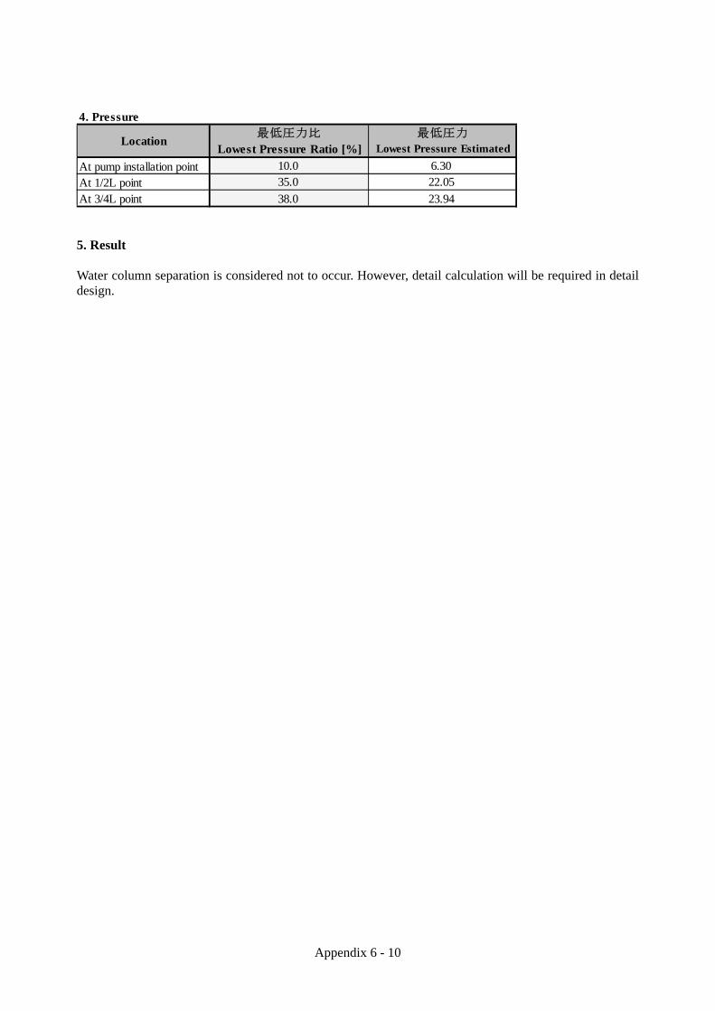
Appendix 6 - 10
4. Pressure
At pump installation pointAt 1/2L pointAt 3/4L point
最低圧力
Lowest Pressure Estimated
6.3022.05
最低圧力比
Lowest Pressure Ratio [%]
10.035.0
Location
38.0 23.94 5. Result Water column separation is considered not to occur. However, detail calculation will be required in detail design.

Appendix 6 - 11
Figure 6.b.3 Pipeline Profile

Appendix 6 - 12
3. Calculation of Transformer Load List
kW Nos Total [kW]
From raw water pump to reclamation process equipment
706.94 1 lot 706.94
Reclaimed Water Transmission Pump 75 3(1) 150
Building Service 60 1 lot 60
Others 10 1 lot 10
3-phase Total [kW] 926.94
Building Service 50 1 lot 50
Laboratory 30 1 lot 30
Others 10 1 lot 10
1-phase Total [kW] 90
1) Formula
Required Capacity P[kVA] = Total Load [kW] × β×α η×φ
Here, φ: Total Power Factor 0.85 η: Total Efficiency 0.85 β: Demand Factor 0.8 α: Allowance Rate 1.1
2) Calculation
1016.94×0.8×1.1
0.85×0.85 = 1,239 [kVA]
3) Result 1,250[kVA] shall be selected since the required capacity amounts to 1,239 [kVA].

Appendix 6 - 13
4. Calculation of Emergency Generator Load List for Emergency Generator
kW Nos Total [kW]
From raw water pump to reclamation process equipment
455.755 1 lot 455.755
Reclaimed Water Transmission Pump 75 1 75
Building Service 18 1 lot 18
Others 10 1 lot 10
3-phase Total [kW] 558.755
Building Service 15 1 lot 15
Laboratory 9 1 lot 9
Others 3 1 lot 3
1-phase Total [kW] 27
(1) Formula Capacity of generator shall exceed the largest among the required capacity calculated using the following formulas. a. PG1: Required capacity for steady operation of all the loads
PG1=ΣP0
ηL×φL ×α×Sf [kVA]
Sf=1+0.6×ΔPΣP0
Here, ΣP0: Total Load for Emergency Generator [kW] Calculation of ΣP0
a) Equipment that the rating is displayed as output kW (such as general induction motor) Pi= Rated Output [kW]
b) Equipment that the rating is displayed as output kVA (such as CVCF) Pi= Rated Output [kVA] × Power Factor (0.9)
c) Rectification equipment Pi= Rated DC Voltage [V] × DC side Rated Current [A]
d) Fluorescent Light and Incandescence Light Pi= Rated Power Consumption or Lamp Power [kW] Referred to as Pi= Rated Output [kVA] x0.8 when [kVA] is used as the unit for fluorescent light output.
ηL: Total Load Efficiency 0.85 φL: Total Load Power Factor 0.8 α: Demand Factor 0.8 ΔP: Total of unbalance part of single phase load
Starting kVA decided by starting method Starting Method β×C
DOL 7.2×1.0 Star Delta 7.2×2/3
Reactor Starting
50% 7.2×0.5 65% 7.2×0.65 80% 7.2×0.8
Kondorfer Starting
50% 7.2×0.25 65% 7.2×0.42 80% 7.2×0.64
Squirrel-Cage Type
VFD Starting 1.2 Wound-Rotor Type 1.2
(Note) In case of closed transition Star Delta starter, β×C shall be 7.2×1/3.

Appendix 6 - 14
b. PG2: Required capacity for allowable voltage drop
PG2=Pm×β×C×Xd'×1-ΔEΔE [kVA]
Here,
Pm: The Maximum Motor Output [kW] β: Starting kVA of the maximum capacity motor per kW [kVA] C: The coefficient decided by starting method Xd': Generator Constant 0.25 ΔE: Allowable Voltage Drop Rate 0.25
c. PG3: Required capacity for starting of the motor with maximum capacity at the end
PG3=fv1
γG {(ΣP0-Pm)×
αηL×φL
+Pm×β×C} [kVA]
Here,
ΣP0: Total Load for Emergency Generator (excludes standby load) [kW]
ηL: Total Load Efficiency 0.85
α: Demand Factor 0.8
Pm: The Maximum Motor Output [kW]
φL: Total Load Power Factor 0.8
β: Starting kVA of the maximum capacity motor per kW [kVA] C: The coefficient decided by starting method
γG: Instant overload capacity of generator 1.5
fv1: Loading Abatement Factor 1.0
(2) Calculation a. PG1: Required capacity for steady operation of all the loads ΣP0=558.755+0×0.9+33.75×0.8=585.8
Sf=1+0.6×27
585.8 =1.028
PG1 =585.8
0.85×0.8 ×0.8×1.028 ≒ 708.4
b. PG2: Required capacity for allowable voltage drop
PG2 = 75×7.2×0.8×0.25×1-0.250.25
≒ 324 c. PG3: Required capacity for starting of the motor with maximum capacity at the end
PG3 = 1.01.5 {(585.8-75)×
0.80.85×0.8 +75×7.2×0.8}
≒ 688.6

Appendix 6 - 15
(3) Result 750[kVA] shall be selected since the required capacity is calculated as 708.4[kVA].
5. Calculation of Fuel Tank 1) Formula
Required capacity of fuel tank Q[m3]=P×be×H×α
d
Here, P: Engine Output [kW] be: Fuel consumption rate [kg/kW・h] H: Operating time [h] α: Allowance Rate 1.1
d: Fuel Density
2) Calculation
Engine Output P[kW] =PG×φG
ηG =
750×0.8 0.923 =650.1
Here, PG: Generator Output
φG: Generator Power Factor ηG: Generator Efficiency
Q=P×be×H×α
d =650.1×0.231×12×1.1
830 = 2.38[m3]
3) Result 2.5[m3] of fuel tank shall be selected as required capacity is 2.38[m3].

Appendix 6 - 16
6.c Design Drawing Transmission pipe plan, transmission pipe cross section, transmission pipe vertical section,
water pipe bridge schematic drawing, and pipe-thrusting method outline drawing are shown in
the attached drawings. Drawing list is shown in the following table.
Table 6.c.1 Drawing List of Transmission Pipe Concept Design
NO. Title Scale Remarks
1-1 Key Plan None
2-1 Transmission Pipe Plan (1) 1/2000
2-2 Transmission Pipe Plan (2) 1/2000
2-3 Transmission Pipe Plan (3) 1/2000
2-4 Transmission Pipe Plan (4) 1/2000
2-5 Transmission Pipe Plan (5) 1/2000
2-6 Transmission Pipe Plan (6) 1/2000
2-7 Transmission Pipe Plan (7) 1/2000
2-8 Transmission Pipe Plan (8) 1/2000
2-9 Transmission Pipe Plan (9) 1/2000
2-10 Transmission Pipe Plan (10) 1/2000
2-11 Transmission Pipe Plan (11) 1/2000
2-12 Transmission Pipe Plan (12) 1/2000
2-13 Transmission Pipe Plan (13) 1/2000
2-14 Transmission Pipe Plan (14) 1/2000
2-15 Transmission Pipe Plan (15) 1/2000
2-16 Transmission Pipe Plan (16) 1/2000
2-17 Transmission Pipe Plan (17) 1/2000
2-18 Transmission Pipe Plan (18) 1/2000
2-19 Transmission Pipe Plan (19) 1/2000
2-20 Transmission Pipe Plan (20) 1/2000
2-21 Transmission Pipe Plan (21) 1/2000

Appendix 6 - 17
NO. Title Scale Remarks
3-1 Transmission Pipe Cross Section (1) 1/100
3-2 Transmission Pipe Cross Section (2) 1/100
3-3 Transmission Pipe Cross Section (3) 1/100
3-4 Transmission Pipe Cross Section (4) 1/100
3-5 Transmission Pipe Cross Section (5) 1/100
3-6 Transmission Pipe Cross Section (6) 1/100
3-7 Transmission Pipe Cross Section (7) 1/100
3-8 Transmission Pipe Cross Section (8) 1/100
3-9 Transmission Pipe Cross Section (9) 1/100
3-10 Transmission Pipe Cross Section (10) 1/100
3-11 Transmission Pipe Cross Section (11) 1/100
3-12 Transmission Pipe Cross Section (12) 1/100
3-13 Transmission Pipe Cross Section (13) 1/100
3-14 Transmission Pipe Cross Section (14) 1/100
3-15 Transmission Pipe Cross Section (15) 1/100
3-16 Transmission Pipe Cross Section (16) 1/100
3-17 Transmission Pipe Cross Section (17) 1/100
3-18 Transmission Pipe Cross Section (18) 1/100
3-19 Transmission Pipe Cross Section (19) 1/100
3-20 Transmission Pipe Cross Section (20) 1/100
3-21 Transmission Pipe Cross Section (21) 1/100
3-22 Transmission Pipe Cross Section (22) 1/100
3-23 Transmission Pipe Cross Section (23) 1/100
3-24 Transmission Pipe Cross Section (24) 1/100
3-25 Transmission Pipe Cross Section (25) 1/100
3-26 Transmission Pipe Cross Section (26) 1/100
3-27 Transmission Pipe Cross Section (27) 1/100
3-28 Transmission Pipe Cross Section (28) 1/100
3-29 Transmission Pipe Cross Section (29) 1/100
3-30 Transmission Pipe Cross Section (30) 1/100
3-31 Transmission Pipe Cross Section (31) 1/100
3-32 Transmission Pipe Cross Section (32) 1/100
3-33 Transmission Pipe Cross Section (33) 1/100
3-34 Transmission Pipe Cross Section (34) 1/100
3-35 Transmission Pipe Cross Section (35) 1/100
3-36 Transmission Pipe Cross Section (36) 1/100
3-37 Transmission Pipe Cross Section (37) 1/100

Appendix 6 - 18
NO. Title Scale Remarks
4-1 Transmission Pipe Vertical Section (1) H=1/2000,V=1/200
4-2 Transmission Pipe Vertical Section (2) H=1/2000,V=1/200
4-3 Transmission Pipe Vertical Section (3) H=1/2000,V=1/200
4-4 Transmission Pipe Vertical Section (4) H=1/2000,V=1/200
4-5 Transmission Pipe Vertical Section (5) H=1/2000,V=1/200
4-6 Transmission Pipe Vertical Section (6) H=1/2000,V=1/200
4-7 Transmission Pipe Vertical Section (7) H=1/2000,V=1/200
4-8 Transmission Pipe Vertical Section (8) H=1/2000,V=1/200
4-9 Transmission Pipe Vertical Section (9) H=1/2000,V=1/200
4-10 Transmission Pipe Vertical Section (10) H=1/2000,V=1/200
4-11 Transmission Pipe Vertical Section (11) H=1/2000,V=1/200
4-12 Transmission Pipe Vertical Section (12) H=1/2000,V=1/200
4-13 Transmission Pipe Vertical Section (13) H=1/2000,V=1/200
4-14 Transmission Pipe Vertical Section (14) H=1/2000,V=1/200
4-15 Transmission Pipe Vertical Section (15) H=1/2000,V=1/200
4-16 Transmission Pipe Vertical Section (16) H=1/2000,V=1/200
4-17 Transmission Pipe Vertical Section (17) H=1/2000,V=1/200
4-18 Transmission Pipe Vertical Section (18) H=1/2000,V=1/200
4-19 Transmission Pipe Vertical Section (19) H=1/2000,V=1/200
4-20 Transmission Pipe Vertical Section (20) H=1/2000,V=1/200
4-21 Transmission Pipe Vertical Section (21) H=1/2000,V=1/200
4-22 Transmission Pipe Vertical Section (22) H=1/2000,V=1/200
4-23 Transmission Pipe Vertical Section (23) H=1/2000,V=1/200
4-24 Transmission Pipe Vertical Section (24) H=1/2000,V=1/200
4-25 Transmission Pipe Vertical Section (25) H=1/2000,V=1/200
5-1 Water Pipe Bridge Layout Plan (1) 1/200
5-2 Water Pipe Bridge Layout Plan (2) 1/200

Appendix 6 - 19

Appendix 6 - 20

Appendix 6 - 21

Appendix 6 - 22
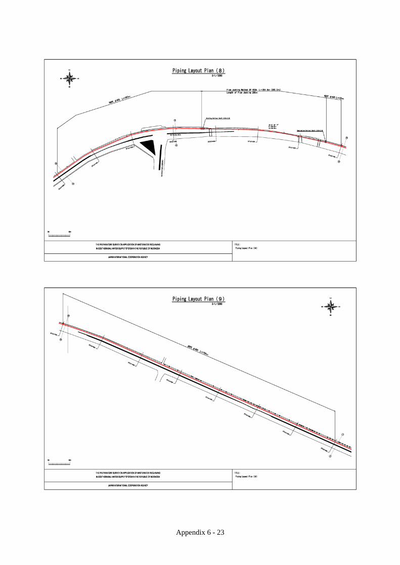
Appendix 6 - 23

Appendix 6 - 24

Appendix 6 - 25

Appendix 6 - 26

Appendix 6 - 27

Appendix 6 - 28

Appendix 6 - 29

Appendix 6 - 30

Appendix 6 - 31

Appendix 6 - 32

Appendix 6 - 33

Appendix 6 - 34

Appendix 6 - 35

Appendix 6 - 36

Appendix 6 - 37

Appendix 6 - 38

Appendix 6 - 39

Appendix 6 - 40

Appendix 6 - 41

Appendix 6 - 42

Appendix 6 - 43

Appendix 6 - 44

Appendix 6 - 45

Appendix 6 - 46

Appendix 6 - 47

Appendix 6 - 48

Appendix 6 - 49

Appendix 6 - 50

Appendix 6 - 51

Appendix 6 - 52

Appendix 6 - 53

Appendix 6 - 54

Appendix 6 - 55

Appendix 6 - 56

Appendix 6 - 57

Appendix 6 - 58

Appendix 6 - 59

Appendix 6 - 60

Appendix 6 - 61

APPENDIX 7
INVESTIGATION DATA OF WATER
DISTRIBUTION AND SUPPLY
FACILITIES

Appendix 7 - 1
APPENDIX 7 INVESTIGATION DATA OF WATER DISTRIBUTION AND SUPPLY FACILITIES
7.a Examination and Repair Strategy of Existing Distribution Pipe The route of existing main distribution pipe is shown as Table 7.a.1. The material of existing distribution pipes is DCIP, the length of each pipe diameter is shown as follows. φ150mm :1,630m φ200mm :1,880m φ300mm : 800m φ400mm :2,170m Total :6,480m The existing distribution pipe could not be confirmed by appearance inspection or etc because it is underground pipe. In detailed design stage, further investigations as follows are necessary for reconstruction. ・Water Leakage Investigation and Intratubular Washing of Existing Pipe ・Replacement of Water Shutoff Valve ・Reconstruction for water leakage part The pipe reconstruction cost was calculated from reconstruction pipe length as 10% of total pipe length because confirmation of water leakage point of existing pipe is difficult.

Appendix 7 - 2
Figure 7.a.1 Route of Existing Distribution Pipe
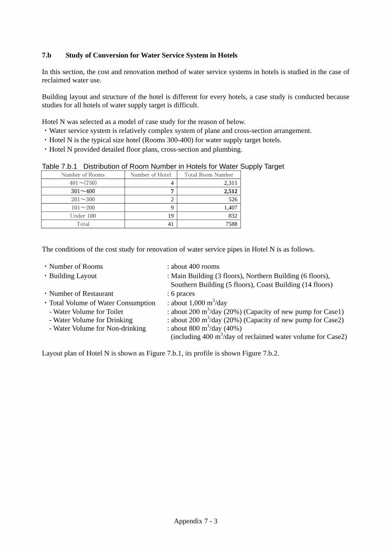
Appendix 7 - 3
7.b Study of Conversion for Water Service System in Hotels In this section, the cost and renovation method of water service systems in hotels is studied in the case of reclaimed water use. Building layout and structure of the hotel is different for every hotels, a case study is conducted because studies for all hotels of water supply target is difficult. Hotel N was selected as a model of case study for the reason of below. ・Water service system is relatively complex system of plane and cross-section arrangement. ・Hotel N is the typical size hotel (Rooms 300-400) for water supply target hotels. ・Hotel N provided detailed floor plans, cross-section and plumbing. Table 7.b.1 Distribution of Room Number in Hotels for Water Supply Target
Number of Rooms Number of Hotel Total Room Number
401~(750) 4 2,311
301~400 7 2,512201~300 2 526
101~200 9 1,407
Under 100 19 832
Total 41 7588
The conditions of the cost study for renovation of water service pipes in Hotel N is as follows. ・Number of Rooms : about 400 rooms ・Building Layout : Main Building (3 floors), Northern Building (6 floors), Southern Building (5 floors), Coast Building (14 floors) ・Number of Restaurant : 6 praces ・Total Volume of Water Consumption : about 1,000 m3/day
- Water Volume for Toilet : about 200 m3/day (20%) (Capacity of new pump for Case1) - Water Volume for Drinking : about 200 m3/day (20%) (Capacity of new pump for Case2) - Water Volume for Non-drinking : about 800 m3/day (40%) (including 400 m3/day of reclaimed water volume for Case2)
Layout plan of Hotel N is shown as Figure 7.b.1, its profile is shown Figure 7.b.2.

Appendix 7 - 4
Figure 7.b.1 Layout Plan of Hotel N (sources: G2011 Google-Map Data)
Figure 7.b.2 Profile of Hotel N (source: http://www.nikkobali.com/jp/) 2 case of renovation design as follows are studied Case 1: Typical Reclaimed Water Service System Case 2: New Clean Water Service System

Appendix 7 - 5
(1) Case 1 Renovation Design According to Case 1, the renovation design model is shown as Figure 7.b.3.
Room Restaurant
Room Room
Room Room
Room Room
Room Room
Room Room
PDAM Water Water Pump Room Room
Water MeterWater Receiving
TankRoom Room
Water Heater& Pump
Room Restaurant
Pipe Duct
Room Restaurant
Room Room
Room Room
Reclaimed Water Room Room
Water MeterWater Receiving
TankWater Pump Room Room
Room Room
PDAM Water Water Pump Room Room
Water MeterWater Receiving
TankRoom Room
Water Heater& Pump
Room Restaurant
Pipe Duct
Figure 7.b.3 Model for Renovation of Water Service Pipes (Case 1) Therefore the renovation work as following items is necessary. ・Installation work of reclaimed water service pipes
(Water Meter – Receiving Tank – Water Pump – Rooms) ・Construction work of water receiving tank for reclaimed water ・Installation work of water meter for reclaimed water ・Installation work of water pump for reclaimed water The image for route of new water service pipe is shown as Figure 7.b.4.
Existing
After Renovation

Appendix 7 - 6
Figure 7.b.4 Image for Route of New Water Service Pipe (Case 1) The existing water meter is located with green mark and the route of new water service is located with blue line on Figure 7.b.4. The conversion cost based on above route is calculated as Table 7.b.2. Table 7.b.2 Conversion Cost in Hotel for Typical Water Service System (Case1)
Item Quantity Unit Unit Price (IDR) Cost (IDR)
Installation work of reclaimed water service pipes
2,420 m 370,000 895,400,000
Construction work of water receiving tank for reclaimed water
1 Set 488,870,000 488,870,000
Installation work of water meter for reclaimed water
1Set
8,000,000 8,000,000
Installation work of water meter for reclaimed water
1Set
100,000,000 100,000,000
Total Cost 1,492,270,000

Appendix 7 - 7
(2) Case 2 Renovation Design According to Case 2, the renovation design model is shown as Figure 7.b.5.
Room Restaurant
Room Room
Room Room
Room Room
Room Room
Room Room
PDAM Water Water Pump Room Room
Water MeterWater Receiving
TankRoom Room
Water Heater& Pump
Room Restaurant
Pipe Duct
Room Restaurant
Room Room
Water ReceivingTank
Water Pump Room Room
Reclaimed Water Room Room
Water Meter Room Room
Room Room
PDAM Water Water Pump Room Room
Water MeterWater Receiving
TankRoom Room
Water Heater& Pump
Room Restaurant
Pipe Duct
H
H
Figure 7.b.5 Model for Renovation of Water Service Pipes (Case 2) Therefore the renovation work as following items is necessary. ・Installation work of reclaimed water service pipes
(For reclaimed water: Water Meter – Receiving Tank) (For PDAM water: Water Meter – Receiving Tank – Water Pump – Restaurants)
・Construction work of water receiving tank for reclaimed water ・Installation work of water meter for reclaimed water ・Installation work of water pump for reclaimed water ・Installation work of water heater for reclaimed water The image for route of new water service pipe is shown as Figure 7.b.6.
Existing
After Renovation

Appendix 7 - 8
Figure 7.b.6 Image for Route of New Water Service Pipe (Case 2) The existing water meter is located with green mark, restaurants are located with red marks and the route of new water service is located with blue line on Figure 7.b.6. The conversion cost based on above route is calculated as Table 7.b.3. Table 7.b.3 Conversion Cost in Hotel for Typical Water Service System (Case2)
Item Quantity Unit Unit Price (IDR) Cost (IDR)
Installation work of reclaimed water service pipes
920 m 363,000 333,960,000
Construction work of water receiving tank for reclaimed water
1 Set 488,870,000 488,870,000
Installation work of water meter for reclaimed water
1Set
20,000,000 20,000,000
Installation work of water meter for reclaimed water
1Set
100,000,000 100,000,000
Installation work of water heater for reclaimed water
6 Set 8,000,000 48,000,000
Total Cost 990,830,000

APPENDIX 8
DATA OF PROJECT COST ESTIMATE

Appendix 8 - 1
APPENDIX 8 DATA OF PROJECT COST ESTIMATE 8.a Component of Project Cost The four main cost components of the reclaimed water supply project cost are construction, engineering services, taxes, operation and maintenance (O&M). These are further categorized as shown in the following table. Table 8.a.1 Components of the Project Cost
Main Item Detail Item (A) Site Preparation (B) Reclamation Plant Construction (C) Transmission Pipe Installation (D) Distribution Reservoir Reconstruction (E) Distribution Pipe Rehabilitation and Installation
【1】Construction
(F) Renovating the Service Pipe Facilities in Each Hotel (A) Detailed Design, Construction Supervision, Other Surveys, etc. (B) Capacity Building
【2】Engineering Services
(C) Publication and Education-related (A) Value-added Tax (VAT) (B) Import Tax
【3】Tax Charges
(C) Surface Water Use Tax (A) Personnel (B) Electricity (C) Chemical (D) Fuel (E) Water Quality Testing (F) Repair and Replacement of parts and equipment (G) Office expenditures
【4】Operation and Maintenance (O&M)
(H) Treated Water Use Rate 8.b Construction Cost Construction costs are calculated for all the facilities required for the project, from the reclamation plant to the renovation of service pipe facilities in each hotel. As explained in Chapter 7, the responsibility for constructing and renovating these facilities is divided between SPC, PDAM Badung and the hotels; and the associated costs are calculated separately for these parties. Construction costs under SPC’s responsibility consist of site preparation, reclamation plant construction and transmission pipeline construction. Construction costs under PDAM’s responsibility consist of distribution reservoir reconstruction, rehabilitation of the existing distribution network and installation of new distribution pipes. The construction costs under the responsibility of each hotel consist of renovation of their service pipe facilities. The detail of each construction cost item is explained in the following. Table 8.b.1 Responsible Organization of the Each Component Items SPC PDAM Hotels (A) Site Preparation ○ (B) Reclamation Plant Construction ○ (C) Transmission Pipe Installation ○ (D) Distribution Reservoir Reconstruction ○ (E) Distribution Pipe Installation ○ (F) Renovating the Service Pipe Facilities in Each Hotel ○

Appendix 8 - 2
(1) Site Preparation Site preparation consists of the following: ・Improvement of the access road to the reclamation plant site ・Cutting down of mangrove trees, digging up of soft soil and removal of concrete debris ・Land reclamation and leveling using purchased soil The land for the reclaimed water supply plant will be provided by the Bali Provincial Government as a precondition of this PPP project (the Bali Provincial Government needs to apply to to the Ministry of Forestry for the license to use the land. (2) Reclamation Plant Construction This cost category covers the construction of the pump facility to convey the secondary effluent from Denpasar WWTP, biological filtration facility, ozonation facility, membrane filtration facility and transmission pump facility. The breakdown by facility type is shown as follows. 1) Main plant construction (civil engineering and architectural works) ・Raw water pumping station ・Biological filtration process building ・Ozonation process building ・Membrane filtration process building ・Site work ・Vehicle purchase ・Connection charge for electrical service 2) Mechanical and Electrical Facility ・Mechanical equipment (including installation) ・Electrical equipment (including installation) (3) Transmission Pipe Installation The transmission pipe from Denpasar WWTP to the existing UPA distribution reservoir would be constructed in four sections, using different pipe installation methods, according to the level of traffic congestion and the ease of pipe installation at the location. The total cost for the transmission pipe installation the sum of the pipe installation costs for each section. The length of each road section is shown below. ・Open cut method (daytime work : about 7.5 km) ・Open cut method (nighttime work : about 7 km from Badung River to Sama River) ・Water pipe bridge method (crossing of river and drainage canal) ・Pipe jacking method (around the airport about 400 m) (4) Distribution Reservoir Reconstruction The existing reservoir does not have a roof and has many cracks and evidence of water leakage. The cost

Appendix 8 - 3
for reconstruction would cover the following: ・Crack repair ・Waterproofing ・Roof construction (5) Distribution Pipe Installation The distribution pipe installation cost would cover the following: ・Rehabilitation of the existing distribution pipes in Nusa Dua ・Installation of new distribution pipes in Benoa ・Installation of new distribution pipe in Sawangan (6) Renovation of Service Pipe Facilities in the Hotels The renovation cost is required to use reclaimed water in the hotels. The unit cost of renovation is calculated in Chapter 6. <Summary of Case 1> The renovation cost would establish a system to supply the reclaimed water to the toilet in each room or floor. <Summary of Case 2> The renovation cost would establish a system to supply the reclaimed water which is mixed with PDAM water and a separate system to supply drinking and cooking water to the restaurants inside the hotels. (7) Total Construction Cost The total construction costs calculated on the conditions by each facility and responsible agency explained above is shown in Table 8.b.2 (Case 1) or Table 8.b.3 (Case 2). The breakdown for each item of construction cost is shown as Table 8.b.4 (Case 1) and Table 8.b.5 (Case 2), the unit price is shown as Table 8.b.6.

Appendix 8 - 4
Table 8.b.2 Construction Cost of Case 1 (1) Construction Cost by Each Facility
JPY (×1,000)LC FC Total Total
【A Site Preparation】
Site Preparation 5,968,887 0 5,968,887 54,257
【B Reclamation Plant Facility】
Structure ConstructionRaw Water Pump Building 976,400 0 976,400 8,875Biological Treatment Building 5,455,191 0 5,455,191 49,588Ozonation Building 7,942,297 0 7,942,297 72,195Membrane Filtration Building 12,454,956 0 12,454,956 113,216Site Work 3,598,539 0 3,598,539 32,711Vehicles 2,070,000 0 2,070,000 18,816Connection Charge for Electricity 631,250 0 631,250 5,738Sub Total (1) 33,128,632 0 33,128,632 301,139
Mechanical and Electrical Facility Mechanical Equipment 28,027,620 24,004,951 52,032,571 472,976Electrical Equipment 35,613,810 0 35,613,810 323,730Sub Total (2) 63,641,430 24,004,951 87,646,381 796,706
Total 96,770,062 24,004,951 120,775,013 1,097,845
【C Water Transmission Pipe】
Water Transmission Pipe 44,144,600 0 44,144,600 401,274
【D Distribution Reservoir】Distribution Reservoir 3,449,933 0 3,449,933 31,360
【E Distribution Pipe】
Distribution Pipe for Nusa Dua 3,342,380 0 3,342,380 30,382Distribution Pipe for Benoa 10,285,000 0 10,285,000 93,491Distribution Pipe for Sawangan 8,465,200 0 8,465,200 76,949Total 22,092,580 0 22,092,580 200,822
【F Renovation of Service Pipe Facilities in the Hotel 】Renovation Cost 29,230,000 0 29,230,000 265,701Total 29,230,000 0 29,230,000 265,701
ItemIDR (×1,000)
(2) Construction Cost by Responsible Agency
JPY (×1,000)LC FC Total Total
SPC Total Construction Cost 146,883,549 24,004,951 170,888,500 1,553,376
PDAM Total Construction Cost 25,542,513 0 25,542,513 232,181
Hotel Total Renovation Cost 29,230,000 0 29,230,000 265,701
Grand Total Construction Cost 201,656,062 24,004,951 225,661,013 2,051,259
ItemIDR (×1,000)

Appendix 8 - 5
Table 8.b.3 Construction Cost of Case 2 (1) Construction Cost by Each Facility
JPY (×1,000)LC FC Total Total
【A Site Preparation】
Site Preparation 6,507,139 0 6,507,139 59,150
【B Reclamation Plant Facility】
Structure ConstructionRaw Water Pump Building 1,224,468 0 1,224,468 11,130Biological Treatment Building 9,387,773 0 9,387,773 85,335Ozonation Building 8,823,814 0 8,823,814 80,208Membrane Filtration Building 14,261,371 0 14,261,371 129,636Site Work 4,357,294 0 4,357,294 39,608Vehicles 2,070,000 0 2,070,000 18,816Connection Charge for Electricity 631,250 0 631,250 5,738Sub Total (1) 40,755,971 0 40,755,971 370,472
Mechanical and Electrical Facility Mechanical Equipment 33,402,949 34,308,417 67,711,366 615,496Electrical Equipment 35,613,810 0 35,613,810 323,730Sub Total (2) 69,016,759 34,308,417 103,325,176 939,226
Total 109,772,730 34,308,417 144,081,147 1,309,698
【C Water Transmission Pipe】
Water Transmission Pipe 56,218,200 0 56,218,200 511,023
【D Distribution Reservoir】Distribution Reservoir 3,449,933 0 3,449,933 31,360
【E Distribution Pipe】
Distribution Pipe for Nusa Dua 3,342,380 0 3,342,380 30,382Distribution Pipe for Benoa 13,326,700 0 13,326,700 121,140Distribution Pipe for Sawangan 10,757,200 0 10,757,200 97,783Total 27,426,280 0 27,426,280 249,305
【F Renovation of Service Pipe Facilities in the Hotel 】Renovation Cost 19,750,000 0 19,750,000 179,528Total 19,750,000 0 19,750,000 179,528
ItemIDR (×1,000)
(2) Construction Cost by Responsible Agency
JPY (×1,000)LC FC Total Total
SPC Total Construction Cost 172,498,069 34,308,417 206,806,486 1,879,871
PDAM Total Construction Cost 30,876,213 0 30,876,213 280,665
Hotel Total Renovation Cost 19,750,000 0 19,750,000 179,528
Grand Total Construction Cost 223,124,281 34,308,417 257,432,698 2,340,063
ItemIDR (×1,000)

Appendix 8 - 6
Table 8.b.4 Breakdown for Each Item of Case 1 Construction Cost
A1
Sit
e P
repa
rati
on f
or T
reat
men
t P
lant
LC
FC
LC
FC
Tot
al
m3
7,59
010
2,00
00
774,
180
077
4,18
0
m3
7,59
056
,600
042
9,59
40
429,
594
(Com
pact
ed u
se b
uy s
oil)
m3
19,8
0014
4,80
00
2,86
7,04
00
2,86
7,04
0
m2
301,
980,
000
059
,400
059
,400
Adm
inis
trat
ive
Roa
d P
avem
ent W
ork
m2
2,91
026
0,30
00
757,
473
075
7,47
3
Adm
inis
trat
ive
Roa
d S
ub-b
ase
(agg
rega
te A
)m
360
033
0,00
00
198,
000
019
8,00
0
Adm
inis
trat
ive
Roa
d S
ub-b
ase
(agg
rega
te B
)m
390
033
0,00
00
297,
000
029
7,00
0
Wid
th=
5m, L
engt
h=3m
m2
155,
720,
000
085
,800
085
,800
Wid
th=
5m, L
engt
h=14
mm
270
5,72
0,00
00
400,
400
040
0,40
0
set
110
0,00
0,00
00
100,
000
010
0,00
0
5,96
8,88
70
5,96
8,88
7
Lan
dfill
Qua
ntit
yU
nit
Spe
cifi
cati
onIt
ems
Ref
eren
ce
New
Bri
dge
Con
stru
ctio
n
New
Bri
dge
Con
stru
ctio
n
Exc
avat
ion
(Roo
t of
Man
grov
e, E
xist
ing
Stru
ctur
e )
Was
te D
ispo
sal (
Roo
t of
Man
grov
e, E
xist
ing
Stru
c
Exi
stin
g B
ridg
e R
emov
al
Uni
t Cos
t (ID
R)
Tot
al C
ost (
1,00
0ID
R)
Gat
e an
d G
uard
Pos
t
Tot
al
B1
Raw
Wat
er P
um
p T
ank
LC
FC
LC
FC
Tot
al
San
d, C
ray
m3
756
46,0
000
34,7
760
34,7
76
BH
m3
580
43,3
000
25,1
140
25,1
14
m3
176
56,6
000
9,96
20
9,96
2
L=
20m
pcs
2312
,940
,000
029
7,62
00
297,
620
m3
720
2,30
00
1,41
60
1,41
6
m3
41,
294,
000
05,
176
05,
176
m3
136
2,53
4,00
00
344,
624
034
4,62
4
t13
.616
,120
,000
021
9,23
20
219,
232
m2
371,
040,
000
038
,480
038
,480
976,
400
097
6,40
0T
otal
Roo
fing
Rei
nfor
ced
Con
cret
e
Rei
nfor
cem
ent
Ref
eren
ce
Fou
ndat
ion
Pile
San
d L
ayer
Exc
avat
ion
Bac
k F
illi
ng
Sur
plus
Soi
l Dis
posa
l
Uni
t Cos
t (ID
R)
Tot
al C
ost (
1,00
0ID
R)
Lev
elin
g C
oncr
ete
Qua
ntit
yU
nit
Spe
cifi
cati
onIt
ems

Appendix 8 - 7
B
2B
iolo
gica
l Tre
atm
ent
Bui
ldin
g
LC
FC
LC
FC
Tot
al
San
d, C
ray
m3
185
46,0
000
8,51
00
8,51
0
BH
m3
743
,300
030
30
303
m3
178
56,6
000
10,0
750
10,0
75
L=
20m
pcs
150
12,9
40,0
000
1,94
1,00
00
1,94
1,00
0
m3
8920
2,30
00
18,0
050
18,0
05
m3
451,
294,
000
058
,230
058
,230
m3
749
2,53
4,00
00
1,89
7,96
60
1,89
7,96
6
t74
.916
,120
,000
01,
207,
388
01,
207,
388
m2
224
1,04
0,00
00
232,
960
023
2,96
0
m2
1,25
264
,500
080
,754
080
,754
5,45
5,19
10
5,45
5,19
1
Rei
nfor
ced
Con
cret
e
Rei
nfor
cem
ent
Sur
plus
Soi
l Dis
posa
l
Fou
ndat
ion
Pile
San
d L
ayer
Lev
elin
g C
oncr
ete
Ref
eren
ce
Exc
avat
ion
Bac
k F
illi
ng
Uni
t Cos
t (ID
R)
Tot
al C
ost (
1,00
0ID
R)
Qua
ntit
yU
nit
Spe
cifi
cati
onIt
ems
Roo
fing
Wat
erpr
oofi
ng
Tot
al
B3
Ozo
nati
on B
uil
din
g
LC
FC
LC
FC
Tot
al
San
d, C
ray
m3
373
46,0
000
17,1
580
17,1
58
BH
m3
1043
,300
043
30
433
m3
363
56,6
000
20,5
460
20,5
46
L=
20m
pcs
172
12,9
40,0
000
2,22
5,68
00
2,22
5,68
0
m3
182
202,
300
036
,819
036
,819
m3
911,
294,
000
011
7,75
40
117,
754
m3
1,10
62,
534,
000
02,
802,
604
02,
802,
604
t11
0.6
16,1
20,0
000
1,78
2,87
20
1,78
2,87
2
m2
765
1,04
0,00
00
795,
600
079
5,60
0
m2
447
64,5
000
28,8
320
28,8
32
m2
114
1,00
0,00
00
114,
000
011
4,00
0
7,94
2,29
70
7,94
2,29
7T
otal
Roo
fing
Wat
erpr
oofi
ng
Cor
rosi
on P
rote
ctio
n C
oatin
g
Ref
eren
ce
Exc
avat
ion
Bac
k F
illi
ng
Uni
t Cos
t (ID
R)
Tot
al C
ost (
1,00
0ID
R)
Qua
ntit
yU
nit
Spe
cifi
cati
onIt
ems
Rei
nfor
ced
Con
cret
e
Rei
nfor
cem
ent
Sur
plus
Soi
l Dis
posa
l
Fou
ndat
ion
Pile
San
d L
ayer
Lev
elin
g C
oncr
ete

Appendix 8 - 8
B
4M
emb
ran
e F
iltr
atio
n B
uil
din
g
LC
FC
LC
FC
Tot
al
San
d, C
ray
m3
1,92
446
,000
088
,504
088
,504
BH
m3
649
43,3
000
28,1
020
28,1
02
m3
1,27
556
,600
072
,165
072
,165
L=
20m
pcs
245
12,9
40,0
000
3,17
0,30
00
3,17
0,30
0
m3
210
202,
300
042
,483
042
,483
m3
105
1,29
4,00
00
135,
870
013
5,87
0
m3
1,58
02,
534,
000
04,
003,
720
04,
003,
720
t15
8.0
16,1
20,0
000
2,54
6,96
00
2,54
6,96
0
m2
1,27
81,
040,
000
01,
329,
120
01,
329,
120
m2
585
64,5
000
37,7
330
37,7
33
set
11,
000,
000,
000
01,
000,
000
01,
000,
000
12,4
54,9
560
12,4
54,9
56
Rei
nfor
ced
Con
cret
e
Rei
nfor
cem
ent
Sur
plus
Soi
l Dis
posa
l
Fou
ndat
ion
Pile
San
d L
ayer
Lev
elin
g C
oncr
ete
Ref
eren
ce
Exc
avat
ion
Bac
k F
illi
ng
Uni
t Cos
t (ID
R)
Tot
al C
ost (
1,00
0ID
R)
Qua
ntit
yU
nit
Spe
cifi
cati
onIt
ems
Roo
fing
Wat
erpr
oofi
ng
Lab
orat
ory
Equ
ipm
ent
Tot
al
B5
Sit
e W
ork
LC
FC
LC
FC
Tot
al
m35
050
0,00
00
175,
000
017
5,00
0
Pav
emen
t Wor
km
22,
900
260,
300
075
4,87
00
754,
870
Sub
-bas
e (a
ggre
gate
A)
m3
580
330,
000
019
1,40
00
191,
400
Sub
-bas
e (a
ggre
gate
B)
m3
870
330,
000
028
7,10
00
287,
100
m2
2,29
050
,800
011
6,33
20
116,
332
m33
21,
431,
000
047
5,09
20
475,
092
set
103,
000,
000
030
,000
030
,000
set
110
0,00
0,00
00
100,
000
010
0,00
0
For
Tra
nsm
issi
on p
ipe
(300
mm
m56
01,
631,
000
091
3,36
00
913,
360
For
Raw
wat
er p
ipe
(300
mm
)m
100
1,63
1,00
00
163,
100
016
3,10
0
For
Dis
char
ge p
ipe
(200
mm
)m
335
1,17
1,00
00
392,
285
039
2,28
5
3,59
8,53
90
3,59
8,53
9T
otal
Pip
e L
ayin
g W
ork
Ref
eren
ce
Law
n G
rass
Dra
inag
e
Fen
ce
Roa
d
Uni
t Cos
t (ID
R)
Tot
al C
ost (
1,00
0ID
R)
Gat
e an
d G
uard
Pos
t
Qua
ntit
yU
nit
Spe
cifi
cati
onIt
ems
Pip
e L
ayin
g W
ork
Roa
d
Ele
ctri
c L
amp
Roa
d
Pip
e L
ayin
g W
ork

Appendix 8 - 9
B
6M
ain
tena
nce
Equ
ipm
ent
LC
FC
LC
FC
Tot
al
Sed
an T
ype
unit
s1
270,
000,
000
270,
000
027
0,00
0
4tun
its
290
0,00
0,00
01,
800,
000
01,
800,
000
2,07
0,00
00
2,07
0,00
0T
otal
Ref
eren
ce
Pat
rol C
ar
Uni
t Cos
t (ID
R)
Tot
al C
ost (
1,00
0ID
R)
Qua
ntit
yU
nit
Spe
cifi
cati
onIt
ems
Tan
ker
Tru
ck
B7
Mac
hin
ery
Con
stru
ctio
n(1
IDR
=0.
0090
9)
LC
FC
LC
FC
Tot
al
unit
s1
6,07
7,33
1,00
017
,569
,307
,000
6,07
7,33
117
,569
,307
23,6
46,6
3815
9,70
5,00
0
unit
s2
225,
000,
000
045
0,00
00
450,
000
unit
s1
216,
000,
000
021
6,00
00
216,
000
unit
s1
21,2
84,2
89,0
006,
435,
644,
000
21,2
84,2
896,
435,
644
27,7
19,9
3358
,500
,000
28,0
27,6
2024
,004
,951
52,0
32,5
71
Item
sR
efer
ence
(JP
Y)
Mac
hine
ry E
quip
men
t
Equ
ipm
ent a
nd P
ipe
Inst
rati
on
Uni
t Cos
t (ID
R)
Tot
al C
ost (
1,00
0ID
R)
Qua
ntit
yU
nit
Spe
cifi
cati
on
Tra
nsm
issi
on P
ump
Tot
al
Cra
ne
B8
Ele
ctri
city
Con
stru
ctio
n(1
IDR
=0.
0090
9)
LC
FC
LC
FC
Tot
al
unit
s1
10,2
90,2
67,0
000
10,2
90,2
670
10,2
90,2
67
unit
s1
2,45
7,00
0,00
00
2,45
7,00
00
2,45
7,00
0
20kV
unit
s1
1,60
2,00
0,00
00
1,60
2,00
00
1,60
2,00
0
unit
s1
7,60
5,00
0,00
00
7,60
5,00
00
7,60
5,00
0
unit
s1
522,
000,
000
052
2,00
00
522,
000
unit
s1
90,0
00,0
000
90,0
000
90,0
00
unit
s1
99,0
00,0
000
99,0
000
99,0
00
unit
s1
7,73
0,54
1,00
00
7,73
0,54
10
7,73
0,54
1
unit
s1
5,21
8,00
2,00
00
5,21
8,00
20
5,21
8,00
2
35,6
13,8
100
35,6
13,8
10T
otal
Ref
eren
ce(J
PY
)
Ele
ctri
city
Equ
ipm
ent f
or M
ain
Fac
ilit
ies
Uni
t Cos
t (ID
R)
Tot
al C
ost (
1,00
0ID
R)
Qua
ntit
yU
nit
Equ
ipm
ent a
nd C
able
Ins
talla
tion
for
Mai
n
Equ
ipm
ent a
nd C
able
Ins
talla
tion
for
Oth
ers
Spe
cifi
cati
onIt
ems
Mon
itor
ing
Dev
ice
Rec
eivi
ng E
lect
rici
ty E
quip
men
t
Ele
ctri
c G
ener
ator
Ele
ctri
city
Equ
ipm
ent f
or T
rans
mis
sion
Pum
p
Mon
itor
ing
Dev
ice
for
UP
A R
eser
voir
Inst
rum
enta
tion
Equ
ipm
ent f
or U
PA
Res
ervo
ir
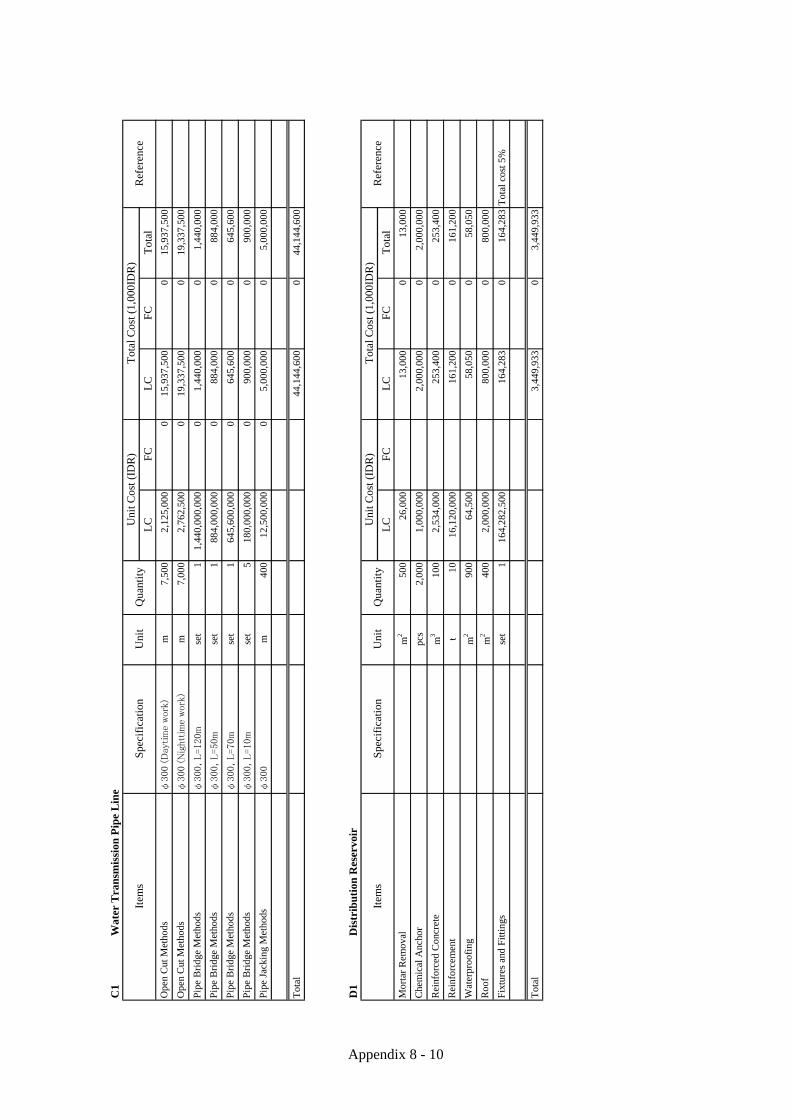
Appendix 8 - 10
C
1W
ater
Tra
nsm
issi
on P
ipe
Lin
e
LC
FC
LC
FC
Tot
al
φ300 (D
aytim
e work
)m
7,50
02,
125,
000
015
,937
,500
015
,937
,500
φ300 (N
ightt
ime
work
)m
7,00
02,
762,
500
019
,337
,500
019
,337
,500
φ300, L=120m
set
11,
440,
000,
000
01,
440,
000
01,
440,
000
φ300, L=50m
set
188
4,00
0,00
00
884,
000
088
4,00
0
φ300, L=70m
set
164
5,60
0,00
00
645,
600
064
5,60
0
φ300, L=10m
set
518
0,00
0,00
00
900,
000
090
0,00
0
φ300
m40
012
,500
,000
05,
000,
000
05,
000,
000
44,1
44,6
000
44,1
44,6
00
Pip
e B
ridg
e M
etho
ds
Pip
e B
ridg
e M
etho
ds
Ref
eren
ceU
nit C
ost (
IDR
)T
otal
Cos
t (1,
000I
DR
)Q
uant
ity
Ope
n C
ut M
etho
ds
Uni
t
Pip
e Ja
ckin
g M
etho
ds
Ope
n C
ut M
etho
ds
Pip
e B
ridg
e M
etho
ds
Spe
cifi
cati
onIt
ems
Tot
al
Pip
e B
ridg
e M
etho
ds
D1
Dis
trib
uti
on R
eser
voir
LC
FC
LC
FC
Tot
al
m2
500
26,0
0013
,000
013
,000
pcs
2,00
01,
000,
000
2,00
0,00
00
2,00
0,00
0
m3
100
2,53
4,00
025
3,40
00
253,
400
t10
16,1
20,0
0016
1,20
00
161,
200
m2
900
64,5
0058
,050
058
,050
m2
400
2,00
0,00
080
0,00
00
800,
000
set
116
4,28
2,50
016
4,28
30
164,
283
Tot
al c
ost 5
%
3,44
9,93
30
3,44
9,93
3T
otal
Ref
eren
ce
Mor
tar
Rem
oval
Che
mic
al A
ncho
r
Uni
t Cos
t (ID
R)
Tot
al C
ost (
1,00
0ID
R)
Qua
ntit
yU
nit
Spe
cifi
cati
onIt
ems
Roo
f
Fix
ture
s an
d F
itti
ngs
Rei
nfor
ced
Con
cret
e
Rei
nfor
cem
ent
Wat
erpr
oofi
ng

Appendix 8 - 11
E
1D
istr
ibu
tion
Pip
e L
ine
for
Nu
sa D
ua
LC
FC
LC
FC
Tot
al
set
125
0,00
0,00
025
0,00
00
250,
000
φ400
m22
05,
442,
000
1,19
7,24
00
1,19
7,24
0
φ300
m80
3,65
2,00
029
2,16
00
292,
160
φ200
m19
02,
302,
000
437,
380
043
7,38
0
φ150
m16
01,
905,
000
304,
800
030
4,80
0
φ400
set
272
,000
,000
144,
000
014
4,00
0
φ200
set
1636
,800
,000
588,
800
058
8,80
0
φ150
set
432
,000
,000
128,
000
012
8,00
0
3,34
2,38
00
3,34
2,38
0
Wat
er S
top
Val
ve R
epla
cem
ent
Wat
er S
top
Val
ve R
epla
cem
ent
Pip
e R
epla
cem
ent D
CIP
Pip
e R
epla
cem
ent D
CIP
Pip
e R
epla
cem
ent D
CIP
Wat
er S
top
Val
ve R
epla
cem
ent
Pip
e R
epla
cem
ent D
CIP
Ref
eren
ce
Wat
er L
eaka
ge I
nves
tigat
ion
Uni
t Cos
t (ID
R)
Tot
al C
ost (
1,00
0ID
R)
Qua
ntit
yU
nit
Spe
cifi
cati
onIt
ems
Tot
al
E2
Dis
trib
uti
on P
ipe
Lin
e fo
r B
enoa
LC
FC
LC
FC
Tot
al
φ200
m5,
800
1,60
6,00
09,
314,
800
09,
314,
800
φ100
m70
01,
386,
000
970,
200
097
0,20
0
10,2
85,0
000
10,2
85,0
00T
otal
Ref
eren
ce
Pip
e L
ayin
g
Pip
e L
ayin
g
Uni
t Cos
t (ID
R)
Tot
al C
ost (
1,00
0ID
R)
Qua
ntit
yU
nit
Spe
cifi
cati
onIt
ems

Appendix 8 - 12
F1
Hot
el C
onve
rsio
n
LC
FCL
CFC
Tot
al
Roo
m7,
900
3,70
0,00
029
,230
,000
029
,230
,000
29,2
30,0
000
29,2
30,0
00T
otal
Ref
eren
ce
Hot
el C
onve
rtin
g C
ost
Uni
t Cos
t (ID
R)
Tot
al C
ost (
1,00
0ID
R)
Qua
ntit
yU
nit
Spe
cifi
cati
onIt
ems
E3
Dis
trib
utio
n P
ipe
Lin
e fo
r Sa
wan
gan
LC
FCL
CFC
Tot
al
φ200
m4,
000
1,60
6,00
06,
424,
000
06,
424,
000
φ100
m1,
200
1,38
6,00
01,
663,
200
01,
663,
200
0.8
m3/m
in 1
8.5
kWse
t2
77,0
00,0
0015
4,00
00
154,
000
Soft S
tart
erse
t1
224,
000,
000
224,
000
022
4,00
0
8,46
5,20
00
8,46
5,20
0
Boo
ster
Pum
p
Ele
ctri
c P
anel
Ref
eren
ce
Pip
e L
ayin
g
Pip
e L
ayin
g
Uni
t Cos
t (ID
R)
Tot
al C
ost (
1,00
0ID
R)
Qua
ntit
yU
nit
Spe
cifi
cati
onIt
ems
Tot
al

Appendix 8 - 13
Table 8.b.5 Breakdown for Each Item of Case 2 Construction Cost
A1
Site
Pre
para
tion
for
Tre
atm
ent
Pla
nt
LC
FCL
CFC
Tot
al
m3
8,61
010
2,00
00
878,
220
087
8,22
0
m3
8,61
056
,600
048
7,32
60
487,
326
(Com
pact
ed u
se b
uy s
oil)
m3
22,4
0014
4,80
00
3,24
3,52
00
3,24
3,52
0
m2
301,
980,
000
059
,400
059
,400
Adm
inis
trat
ive
Roa
d P
avem
ent W
ork
m2
2,91
026
0,30
00
757,
473
075
7,47
3
Adm
inis
trat
ive
Roa
d S
ub-b
ase
(agg
rega
te A
)m
360
033
0,00
00
198,
000
019
8,00
0
Adm
inis
trat
ive
Roa
d S
ub-b
ase
(agg
rega
te B
)m
390
033
0,00
00
297,
000
029
7,00
0
Wid
th=
5m, L
engt
h=3m
m2
155,
720,
000
085
,800
085
,800
Wid
th=
5m, L
engt
h=14
mm
270
5,72
0,00
00
400,
400
040
0,40
0
set
110
0,00
0,00
00
100,
000
010
0,00
0
6,50
7,13
90
6,50
7,13
9T
otal
Ref
eren
ce
New
Bri
dge
Con
stru
ctio
n
New
Bri
dge
Con
stru
ctio
n
Exc
avat
ion
(Roo
t of
Man
grov
e, E
xist
ing
Stru
ctur
e )
Was
te D
ispo
sal (
Roo
t of
Man
grov
e, E
xist
ing
Stru
c
Exi
stin
g B
ridg
e R
emov
al
Uni
t Cos
t (ID
R)
Tot
al C
ost (
1,00
0ID
R)
Gat
e an
d G
uard
Pos
t
Lan
dfill
Qua
ntit
yU
nit
Spe
cifi
cati
onIt
ems
B1
Raw
Wat
er P
um
p T
ank
LC
FCL
CFC
Tot
al
Sand
, Cra
ym
383
746
,000
038
,502
038
,502
BH
m3
616
43,3
000
26,6
730
26,6
73
m3
221
56,6
000
12,5
090
12,5
09
L=
20m
pcs
2912
,940
,000
037
5,26
00
375,
260
m3
1020
2,30
00
2,02
30
2,02
3
m3
51,
294,
000
06,
470
06,
470
m3
172
2,53
4,00
00
435,
848
043
5,84
8
t17
.216
,120
,000
027
7,26
40
277,
264
m2
481,
040,
000
049
,920
049
,920
1,22
4,46
80
1,22
4,46
8
Lev
elin
g C
oncr
ete
Qua
ntit
yU
nit
Spe
cifi
cati
onIt
ems
Ref
eren
ce
Foun
datio
n P
ile
Sand
Lay
er
Exc
avat
ion
Bac
k Fi
lling
Surp
lus
Soil
Dis
posa
l
Uni
t Cos
t (ID
R)
Tot
al C
ost (
1,00
0ID
R)
Rei
nfor
ced
Con
cret
e
Rei
nfor
cem
ent
Roo
fing
Tot
al

Appendix 8 - 14
B
2B
iolo
gica
l Tre
atm
ent
Bui
ldin
g
LC
FCL
CFC
Tot
al
Sand
, Cra
ym
330
346
,000
013
,938
013
,938
BH
m3
843
,300
034
60
346
m3
295
56,6
000
16,6
970
16,6
97
L=
20m
pcs
266
12,9
40,0
000
3,44
2,04
00
3,44
2,04
0
m3
147
202,
300
029
,738
029
,738
m3
741,
294,
000
095
,756
095
,756
m3
1,27
72,
534,
000
03,
235,
918
03,
235,
918
t12
7.7
16,1
20,0
000
2,05
8,52
40
2,05
8,52
4
m2
327
1,04
0,00
00
340,
080
034
0,08
0
m2
2,39
964
,500
015
4,73
60
154,
736
9,38
7,77
30
9,38
7,77
3T
otal
Roo
fing
Wat
erpr
oofi
ng
Ref
eren
ce
Exc
avat
ion
Bac
k Fi
lling
Uni
t Cos
t (ID
R)
Tot
al C
ost (
1,00
0ID
R)
Qua
ntit
yU
nit
Spe
cifi
cati
onIt
ems
Rei
nfor
ced
Con
cret
e
Rei
nfor
cem
ent
Surp
lus
Soil
Dis
posa
l
Foun
datio
n P
ile
Sand
Lay
er
Lev
elin
g C
oncr
ete
B3
Ozo
nati
on B
uil
din
g
LC
FCL
CFC
Tot
al
Sand
, Cra
ym
337
346
,000
017
,158
017
,158
BH
m3
1043
,300
043
30
433
m3
363
56,6
000
20,5
460
20,5
46
L=
20m
pcs
197
12,9
40,0
000
2,54
9,18
00
2,54
9,18
0
m3
182
202,
300
036
,819
036
,819
m3
911,
294,
000
011
7,75
40
117,
754
m3
1,23
42,
534,
000
03,
126,
956
03,
126,
956
t12
3.4
16,1
20,0
000
1,98
9,20
80
1,98
9,20
8
m2
683
1,04
0,00
00
710,
320
071
0,32
0
m2
658
64,5
000
42,4
410
42,4
41
m2
213
1,00
0,00
00
213,
000
021
3,00
0
8,82
3,81
40
8,82
3,81
4
Rei
nfor
ced
Con
cret
e
Rei
nfor
cem
ent
Surp
lus
Soil
Dis
posa
l
Foun
datio
n P
ile
Sand
Lay
er
Lev
elin
g C
oncr
ete
Ref
eren
ce
Exc
avat
ion
Bac
k Fi
lling
Uni
t Cos
t (ID
R)
Tot
al C
ost (
1,00
0ID
R)
Qua
ntit
yU
nit
Spe
cifi
cati
onIt
ems
Roo
fing
Wat
erpr
oofi
ng
Cor
rosi
on P
rote
ctio
n C
oatin
g
Tot
al

Appendix 8 - 15
B
4M
emb
ran
e F
iltr
atio
n B
uil
din
g
LC
FCL
CFC
Tot
al
Sand
, Cra
ym
32,
422
46,0
000
111,
412
011
1,41
2
BH
m3
706
43,3
000
30,5
700
30,5
70
m3
1,71
656
,600
097
,126
097
,126
L=
20m
pcs
291
12,9
40,0
000
3,76
5,54
00
3,76
5,54
0
m3
256
202,
300
051
,789
051
,789
m3
128
1,29
4,00
00
165,
632
016
5,63
2
m3
1,84
82,
534,
000
04,
682,
832
04,
682,
832
t18
4.8
16,1
20,0
000
2,97
8,97
60
2,97
8,97
6
m2
1,27
81,
040,
000
01,
329,
120
01,
329,
120
m2
750
64,5
000
48,3
750
48,3
75
set
11,
000,
000,
000
01,
000,
000
01,
000,
000
14,2
61,3
710
14,2
61,3
71T
otal
Roo
fing
Wat
erpr
oofi
ng
Lab
orat
ory
Equ
ipm
ent
Ref
eren
ce
Exc
avat
ion
Bac
k Fi
lling
Uni
t Cos
t (ID
R)
Tot
al C
ost (
1,00
0ID
R)
Qua
ntit
yU
nit
Spe
cifi
cati
onIt
ems
Rei
nfor
ced
Con
cret
e
Rei
nfor
cem
ent
Surp
lus
Soil
Dis
posa
l
Foun
datio
n P
ile
Sand
Lay
er
Lev
elin
g C
oncr
ete
B5
Site
Wor
k
LC
FCL
CFC
Tot
al
m40
050
0,00
00
200,
000
020
0,00
0
Pav
emen
t Wor
km
23,
200
260,
300
083
2,96
00
832,
960
Sub
-bas
e (a
ggre
gate
A)
m3
640
330,
000
021
1,20
00
211,
200
Sub
-bas
e (a
ggre
gate
B)
m3
960
330,
000
031
6,80
00
316,
800
m2
2,50
050
,800
012
7,00
00
127,
000
m37
01,
431,
000
052
9,47
00
529,
470
set
103,
000,
000
030
,000
030
,000
set
110
0,00
0,00
00
100,
000
010
0,00
0
For
Tra
nsm
issi
on p
ipe
(400
mm
m55
82,
230,
000
01,
244,
340
01,
244,
340
For
Raw
wat
er p
ipe
(400
mm
)m
992,
230,
000
022
0,77
00
220,
770
For
Dis
char
ge p
ipe
(300
mm
)m
334
1,63
1,00
00
544,
754
054
4,75
4
4,35
7,29
40
4,35
7,29
4
Pip
e L
ayin
g W
ork
Roa
d
Ele
ctri
c L
amp
Roa
d
Pip
e L
ayin
g W
ork
Qua
ntit
yU
nit
Spe
cifi
cati
onIt
ems
Ref
eren
ce
Law
n G
rass
Dra
inag
e
Fenc
e
Roa
d
Uni
t Cos
t (ID
R)
Tot
al C
ost (
1,00
0ID
R)
Gat
e an
d G
uard
Pos
t
Pip
e L
ayin
g W
ork
Tot
al

Appendix 8 - 16
B
6M
aint
enan
ce E
quip
men
t
LC
FCL
CFC
Tot
al
Seda
n T
ype
unit
s1
270,
000,
000
270,
000
027
0,00
0
4tun
its
290
0,00
0,00
01,
800,
000
01,
800,
000
2,07
0,00
00
2,07
0,00
0
Tan
ker
Tru
ck
Ref
eren
ce
Pat
rol C
ar
Uni
t Cos
t (ID
R)
Tot
al C
ost (
1,00
0ID
R)
Qua
ntit
yU
nit
Spe
cifi
cati
onIt
ems
Tot
al
B7
Mac
hin
ery
Con
stru
ctio
n(1
IDR
=0.
0090
9)
LC
FCL
CFC
Tot
al
unit
s1
7,78
0,61
7,00
025
,504
,456
,000
7,78
0,61
725
,504
,456
33,2
85,0
7323
1,83
5,50
0
unit
s3
168,
750,
000
050
6,25
00
506,
250
unit
s1
162,
000,
000
016
2,00
00
162,
000
unit
s1
24,9
54,0
81,7
508,
803,
961,
000
24,9
54,0
828,
803,
961
33,7
58,0
4380
,028
,000
33,4
02,9
4934
,308
,417
67,7
11,3
66
Cra
ne
Item
s
Tot
al
Ref
eren
ce(J
PY
)
Mac
hine
ry E
quip
men
t
Equ
ipm
ent a
nd P
ipe
Inst
ratio
n
Uni
t Cos
t (ID
R)
Tot
al C
ost (
1,00
0ID
R)
Qua
ntit
yU
nit
Spe
cifi
cati
on
Tra
nsm
issi
on P
ump
B8
Ele
ctri
city
Con
stru
ctio
n(1
IDR
=0.
0090
9)
LC
FCL
CFC
Tot
al
unit
s1
12,1
29,5
07,0
000
12,1
29,5
070
12,1
29,5
07
unit
s1
2,45
7,00
0,00
00
2,45
7,00
00
2,45
7,00
0
20kV
unit
s1
1,20
1,50
0,00
00
1,20
1,50
00
1,20
1,50
0
unit
s1
5,70
3,75
0,00
00
5,70
3,75
00
5,70
3,75
0
unit
s1
445,
500,
000
044
5,50
00
445,
500
unit
s1
67,5
00,0
000
67,5
000
67,5
00
unit
s1
74,2
50,0
000
74,2
500
74,2
50
unit
s1
9,03
9,30
3,00
00
9,03
9,30
30
9,03
9,30
3
unit
s1
4,49
5,50
0,00
00
4,49
5,50
00
4,49
5,50
0
35,6
13,8
100
35,6
13,8
10
Item
s
Mon
itori
ng D
evic
e
Rec
eivi
ng E
lect
rici
ty E
quip
men
t
Ele
ctri
c G
ener
ator
Ele
ctri
city
Equ
ipm
ent f
or T
rans
mis
sion
Pum
p
Mon
itori
ng D
evic
e fo
r U
PA
Res
ervo
ir
Inst
rum
enta
tion
Equ
ipm
ent f
or U
PA
Res
ervo
ir
Equ
ipm
ent a
nd C
able
Ins
talla
tion
for
Mai
n
Ref
eren
ce(J
PY
)
Ele
ctri
city
Equ
ipm
ent f
or M
ain
Faci
litie
s
Uni
t Cos
t (ID
R)
Tot
al C
ost (
1,00
0ID
R)
Qua
ntit
yU
nit
Spe
cifi
cati
on
Equ
ipm
ent a
nd C
able
Ins
talla
tion
for
Oth
ers
Tot
al

Appendix 8 - 17
D1
Dis
trib
uti
on R
eser
voir
LC
FC
LC
FC
Tot
al
m2
500
26,0
0013
,000
013
,000
pcs
2,00
01,
000,
000
2,00
0,00
00
2,00
0,00
0
m3
100
2,53
4,00
025
3,40
00
253,
400
t10
16,1
20,0
0016
1,20
00
161,
200
m2
900
64,5
0058
,050
058
,050
m2
400
2,00
0,00
080
0,00
00
800,
000
set
116
4,28
2,50
016
4,28
30
164,
283
Tot
al c
ost 5
%
3,44
9,93
30
3,44
9,93
3T
otal
Ref
eren
ce
Mor
tar
Rem
oval
Che
mic
al A
ncho
r
Uni
t Cos
t (ID
R)
Tot
al C
ost (
1,00
0ID
R)
Qua
ntit
yU
nit
Spe
cifi
cati
onIt
ems
Roo
f
Fixt
ures
and
Fitt
ings
Rei
nfor
ced
Con
cret
e
Rei
nfor
cem
ent
Wat
erpr
oofi
ng
C1
Wat
er T
rans
mis
sion
Pip
e L
ine
LC
FC
LC
FC
Tot
al
φ400 (D
aytim
e work
)m
7,50
02,
782,
000
020
,865
,000
020
,865
,000
φ400 (N
ightt
ime
work
)m
7,00
03,
616,
600
025
,316
,200
025
,316
,200
φ400, L=120m
set
11,
800,
000,
000
01,
800,
000
01,
800,
000
φ400, L=50m
set
11,
105,
000,
000
01,
105,
000
01,
105,
000
φ400, L=70m
set
180
7,00
0,00
00
807,
000
080
7,00
0
φ400, L=10m
set
522
5,00
0,00
00
1,12
5,00
00
1,12
5,00
0
φ400
m40
013
,000
,000
05,
200,
000
05,
200,
000
56,2
18,2
000
56,2
18,2
00
Pip
e B
ridg
e M
etho
ds
Tot
al
Uni
t
Pip
e Ja
ckin
g M
etho
ds
Ope
n C
ut M
etho
ds
Pip
e B
ridg
e M
etho
ds
Spe
cifi
cati
onIt
ems
Pip
e B
ridg
e M
etho
ds
Pip
e B
ridg
e M
etho
ds
Ref
eren
ceU
nit C
ost (
IDR
)T
otal
Cos
t (1,
000I
DR
)Q
uant
ity
Ope
n C
ut M
etho
ds

Appendix 8 - 18
E
1D
istr
ibu
tion
Pip
e L
ine
for
Nu
sa D
ua
LC
FCL
CFC
Tot
al
set
125
0,00
0,00
025
0,00
00
250,
000
φ400
m22
05,
442,
000
1,19
7,24
00
1,19
7,24
0
φ300
m80
3,65
2,00
029
2,16
00
292,
160
φ200
m19
02,
302,
000
437,
380
043
7,38
0
φ150
m16
01,
905,
000
304,
800
030
4,80
0
φ400
set
272
,000
,000
144,
000
014
4,00
0
φ200
set
1636
,800
,000
588,
800
058
8,80
0
φ150
set
432
,000
,000
128,
000
012
8,00
0
3,34
2,38
00
3,34
2,38
0
Wat
er S
top
Val
ve R
epla
cem
ent
Wat
er S
top
Val
ve R
epla
cem
ent
Pip
e R
epla
cem
ent D
CIP
Pip
e R
epla
cem
ent D
CIP
Pip
e R
epla
cem
ent D
CIP
Wat
er S
top
Val
ve R
epla
cem
ent
Pip
e R
epla
cem
ent D
CIP
Ref
eren
ce
Wat
er L
eaka
ge I
nves
tigat
ion
Uni
t Cos
t (ID
R)
Tot
al C
ost (
1,00
0ID
R)
Qua
ntit
yU
nit
Spe
cifi
cati
onIt
ems
Tot
al
E2
Dis
trib
uti
on P
ipe
Lin
e fo
r B
enoa
LC
FCL
CFC
Tot
al
φ300
m5,
800
2,12
5,00
012
,325
,000
012
,325
,000
φ150
m70
01,
431,
000
1,00
1,70
00
1,00
1,70
0
13,3
26,7
000
13,3
26,7
00
Ref
eren
ce
Pip
e L
ayin
g
Pip
e L
ayin
g
Uni
t Cos
t (ID
R)
Tot
al C
ost (
1,00
0ID
R)
Qua
ntit
yU
nit
Spe
cifi
cati
onIt
ems
Tot
al

Appendix 8 - 19
E
3D
istr
ibut
ion
Pip
e L
ine
for
Saw
anga
n
LC
FCL
CFC
Tot
al
φ300
m4,
000
2,12
5,00
08,
500,
000
08,
500,
000
φ150
m1,
200
1,43
1,00
01,
717,
200
01,
717,
200
1.5
m3/m
in 1
8.5
kWse
t2
110,
000,
000
220,
000
022
0,00
0
Soft S
tart
erse
t1
320,
000,
000
320,
000
032
0,00
0
10,7
57,2
000
10,7
57,2
00T
otal
Ref
eren
ce
Pip
e L
ayin
g
Pip
e L
ayin
g
Uni
t Cos
t (ID
R)
Tot
al C
ost (
1,00
0ID
R)
Qua
ntit
yU
nit
Spe
cifi
cati
onIt
ems
Boo
ster
Pum
p
Ele
ctri
c P
anel
F1
Hot
el C
onve
rsio
n
LC
FCL
CFC
Tot
al
Roo
m7,
900
2,50
0,00
019
,750
,000
019
,750
,000
19,7
50,0
000
19,7
50,0
00
Ref
eren
ce
Hot
el C
onve
rtin
g C
ost
Uni
t Cos
t (ID
R)
Tot
al C
ost (
1,00
0ID
R)
Qua
ntit
yU
nit
Spe
cifi
cati
onIt
ems
Tot
al

Appendix 8 - 20
Table 8.b.6 Unit Price for Construction Cost
IDR YENExcavation Root of Mangrove, Existing Structure m3 102,000
Excavation BH, Sand, Clay, Gravel m3 46,000
Excavation BH, Rock m3 102,000
Backfilling by purchase Soil m3 145,000
Backfilling BH m3 43,300
Backfilling Bulldozer m3 20,000
Backfilling (Compacted use buy soil) m3 144,800
Surplus Soil Disposal m3 56,600
Waste Disposal m3 56,600
Sand Layer m3 202,300
Leveling Concrete m3 1,294,000
Reinforced Concrete Including formwork m3 2,534,000Reinforcement Bar With rebar fabrication and assembly t 16,120,000Roof Without slab and beam m2 1,040,000
Roof m2 2,000,000Pile φ300 m 647,000Pile φ300, L=20m pcs 12,940,000Pavement work block m2 260,300Cube Stone m 148,300Sub-base (aggregate A) m3 330,000
Sub-base (aggregate B) m3 330,000PVC Pipe φ=150mm without Pavement m 1,025,000PVC Pipe φ=200mm without Pavement m 1,171,000PVC Pipe φ=300mm without Pavement m 1,631,000HDPE Pipe φ=400mm without Pavement m 2,230,000PVC Pipe φ=150mm with Pavement m 1,431,000PVC Pipe φ=200mm with Pavement m 1,606,000PVC Pipe φ=300mm with Pavement m 2,125,000HDPE Pipe φ=400mm with Pavement m 2,782,000DCIP Pipe φ=150mm with Pavement m 1,905,000DCIP Pipe φ=200mm with Pavement m 2,302,000DCIP Pipe φ=300mm with Pavement m 3,652,000DCIP Pipe φ=400mm with Pavement m 5,442,000Water Stop Valve Replacement φ=400mm set 72,000,000Water Stop Valve Replacement φ=200mm set 36,800,000Water Stop Valve Replacement φ=150mm set 32,000,000Pipe Bridge φ=400mm, L=120m set 1,800,000,000Pipe Bridge φ=400mm, L=70m set 1,105,000,000Pipe Bridge φ=400mm, L=50m set 807,000,000Pipe Bridge φ=400mm, L=10m set 225,000,000Pipe Bridge φ=300mm, L=120m set 1,440,000,000Pipe Bridge φ=300mm, L=70m set 884,000,000Pipe Bridge φ=300mm, L=50m set 645,600,000Pipe Bridge φ=300mm, L=10m set 180,000,000Pipe Jacking φ=400mm m 13,000,000Pipe Jacking φ=300mm m 12,500,000Laboratory Equipment set 1,000,000,000Mortar Removal m2 26,000Chemical Anchor set 100,000Waterproofing m2 64,500
Protecting Coating for corrosion protection coating m2 1,000,000Electric Lamp set 3,000,000Lawn Grass m2 50,800Fence H=1.2m m 500,000Gate and Guard Post set 100,000,000Bridge Removal m2 1,980,000
Bridge Construction m2 5,720,000
Demolish m3 100,000Water Leakage Investigation set 250,000,000Booster Pump 1.5m3/min 18.5kw set 110,000,000Electric Panel Soft Starter set 320,000,000Converting Cost for Case1 (for Room Toilet) room 3,700,000Converting Cost for Case2 (for Restaurant) room 2,500,000
RemarksItems Specification UnitUnit Price

Appendix 8 - 21
8.c Engineering Service 8.c.1 Cost of Detailed Design, Construction Supervision and Surveys This cost is calculated as the sum of the following cost items. ・Detailed design ・Construction supervision ・Project management during construction ・EIA implementation ・Additional ground and geological surveys ・Inspection of the existing distribution reservoir and distribution pipes (originally used for irrigation) The detailed design and construction supervision costs are calculated based on the estimated required man-months (MM) of foreign and local engineers as shown below, including office expenses, etc. ・Foreign Engineer : 86 MM ・Local Engineer : 275 MM 8.c.2 Capacity Building and Promotion The capacity building and promotion activities are being conducted at the pilot reclamation plant in Denpasar WWTP. The cost of capacity building and promotion is excluded from the total project cost because it is a precondition of the project that the major part of the promotion should be finished before the confirmation of the reclaimed water demand at the target hotels.

Appendix 8 - 22
Table 8.c.1 Spreadsheet for Engineering Services Cost Unit Unit Price Total Quantity Total Amount
1. Foreign Cost1. Remuneration for Professional A yen Japanese Yen
Foreign Staff1-1 Foreign Staff
A- 1 Consulting Services - Team Leader M/M 3,200,000 22 70,400,000A- 2 Sub-Team Leader - Pipe Line Engineer M/M 3,000,000 9 27,000,000A- 3 Civil Engineer for Transmission Pipe M/M 2,800,000 3 8,400,000A- 4 Sub-Team Leader - Treatment Plant/Pump Station M/M 3,000,000 9 27,000,000A- 5 Civil / Structural Engineer M/M 2,800,000 4 11,200,000A- 6 Mechanical Engineer M/M 2,800,000 12 33,600,000A- 7 Electrical Engineer M/M 2,800,000 12 33,600,000A- 8 Architect M/M 2,800,000 3 8,400,000A- 9 Document Specialist M/M 2,800,000 5 14,000,000A- 10 Cost Estimator M/M 2,800,000 3 8,400,000A- 11 Environmental Specialist M/M 2,800,000 4 11,200,000
862. Direct Cost
1 International Air Fare nos 200,000 45 9,000,000262,200,000
Unit Unit Price Total Quantity Total AmountII. Local Cost
1. Remuneration for Professional B IDR IDRB- 1 Deputy Team Leader M/M 33,003,000 45 1,485,135,000B- 2 Geotechnical Engineer M/M 27,503,000 4 110,012,000B- 3 Topographic Surveyor M/M 27,503,000 6 165,018,000B- 4 Pipe Line Engineer M/M 27,503,000 16 440,048,000B- 5 Civil Engineer M/M 27,503,000 16 440,048,000B- 6 Structural Engineer M/M 27,503,000 6 165,018,000B- 7 Mechanical Engineer M/M 27,503,000 17 467,551,000B- 8 Electrical Engineer M/M 27,503,000 17 467,551,000B- 9 Architect M/M 27,503,000 7 192,521,000B- 10 Document Specialist M/M 27,503,000 6 165,018,000B- 11 Environmental Expert M/M 27,503,000 7 192,521,000B- 12 Quantity Surveyor M/M 27,503,000 46 1,265,138,000B- 13 Chief Inspector M/M 16,502,000 41 676,582,000B- 14 Inspector M/M 11,001,000 41 451,041,000
2752. Remuneration for Supporting Staffs
1-7 Project OfficeC- 1 Office Manager M/M 10,000,000 45 450,000,000C- 2 Accountant M/M 10,000,000 45 450,000,000C- 3 CAD Support for Pipe Line M/M 10,000,000 20 200,000,000C- 4 CAD Support for Civil Works and Structural M/M 10,000,000 5 50,000,000C- 5 CAD Support for M & E M/M 10,000,000 20 200,000,000C- 6 Translator / Interpreter M/M 10,000,000 34 340,000,000C- 7 Secretary M/M 5,000,000 45 225,000,000C- 8 Security Guard M/M 1,000,000 135 135,000,000C- 9 Office Boy M/M 1,000,000 54 54,000,000
4033. Direct Cost
1 Accommodation for Professional A Month 33,003,000 86 2,838,258,0002 Accommodation for Professional B Month 3,300,000 275 907,500,0003 Vehicle Rental Month/Car 11,001,000 120 1,320,120,0004 Office Rental Month 22,002,000 45 990,090,0005 International Communications Month 2,200,000 45 99,000,0006 Domestic Communications Month 2,200,000 45 99,000,0007 Office Maintenance Month 5,501,000 45 247,545,0008 Office Furniture and Equipment Ls 220,022,000 1 220,022,0009 Report Preparation nos 550,000 45 24,750,000
10 Software (CAD etc) Ls 110,011,000 1 110,011,00011 Topographic Survey Ls 110,011,000 1 110,011,00012 Geological Investigation Ls 165,017,000 1 165,017,00013 EIA Ls 1,650,165,017 1 1,650,165,017
17,568,691,017
Grand Total for Detail Design and Supervision Yen 421,899,401
Total
Total
Description
Description

Appendix 8 - 23
8.d Tax Charges The following taxes are estimated as part of the project cost. (1) Value-added Tax (VAT) VAT is estimated at 10% of the local currency portions of the project cost. (2) Import Duty The import tax depends on the items to be imported but the import tax is about 10% of the total price of the equipment to be imported, based on the experience with the construction of the pilot reclamation plant. According to the investigate and examine the results with the support of the tax consultant office in Indonesia, there is a possibility that the reclaimed water project will be exempted from import tax if import duty exemption as stipulated in the Ministry of Finance Regulation No. 101/PMK.04/2007 is applicable to this Project. Contents of the tax consultant office are shown below. 1) Minister of Finance defines in the provision, exempt from import duties pertaining to the import of
raw materials and equipment to be used to prevent environmental pollution. Exemption shall be applied to the waste disposal or industry companies. These equipments can be used for other purposes or be transferred to others with the permission of the Directorate General of Customs, if the equipments were used as intended for two years from the import.
2) Definition of "waste" is the relevant provision has not been specified. In addition, the SPC to the
management of the reclaimed water project is unclear whether the applicable to “waste disposal company” under such provision, but this project is considered to be business in line with the spirit of the law. Therefore the local tax office in Indonesia recommended that the SPC submits an application for the approval of the import tax exemption to the Ministry of Directorate General of Taxation with the following documents after the project approval. - Investment Coordinating Board approval - Tax ID card issued by the Revenue Department - Registered businesses VAT (PKP) - Details of materials and equipments (amount, type and specifications) - Letter of recommendation by the Ministry of the Environment and Environmental Committee (It
describes that these equipments entail no adverse consequence to the environment during the waste treatment and these are recommended the materials and equipments for using to waste treatment.)
Application for approval of import tax exemption is after the establishment of SPC, but the project costs in this survey are exempt from import tax as a prerequisite for the calculations. (3) Surface Water Use Tax The surface water use tax will be imposed on the Indonesian law (28/2009), if the water is use as a water source of tap water. The operation and tax rate are defined by the local government regulations. The taxable water is only surface water and groundwater on these regulations, but there is no provision for the treated wastewater from secondary treatment. Table 8.d.1 Laws, Regulation and Tax Rate for Water Source
Water source Laws and regulations Tax rates 1 Surface water Regulation of Bali (16/2009, Revision 1/2011) 10% of water price 2 Ground water ( In case of Badung Regency)
Regulation of Badung Regency (1/2011) 20% of water price

Appendix 8 - 24
The definition of surface water in Indonesian law (7/2004, GR42/2008) has been defined as "all the water on the ground", but the definition in Bali regulations (1/2011) has been defined as excluding the seawater on the land and sea. Therefore the use of seawater in the state of Bali is not subject to taxation. According to the results of request to investigate and examine the law firm and tax consultant offices in Indonesia about whether the surface water should be regarded as treated wastewater, it is necessary to confirmation and agreement of the relevant agencies of Bali government but they think that there is unreasonable to tax the treated wastewater as surface water from the following two reasons.
1) The treated wastewater has been discharged to the sea so that this water isn’t used in fact. The treated wastewater is the seawater rather than the surface water if it is dared to classify.
2) The treated wastewater does not have a valuation from the viewpoint of taxation. Based on the above-mentioned expert opinion, the treated wastewater is considered as a tax-free advance in this survey. 8.e Operation and Maintenance Cost The annual operation and maintenance costs include costs for personnel, electricity, chemicals, fuel, water quality tests, repairs and replacements, and office expenditures, as explained below. The details are presented in Table 8.e.3 to 8.e.10. (1) Personnel The cost of Case 1 covers to employ 22 staffs for the management, administration, finance and technical departments. The cost of Case 2 covers to employ 24 staffs. The details are presented in Section 9.4. (2) Electricity The electricity cost is calculated by multiplying the unit price from electricity by the expected annual average electrical consumption of SPC. The unit price for electricity is set according to the electricity price list (2010) of PT PLN (PERSERO: Indonesian Electric Power Public Corporation). (3) Chemicals The annual chemicals cost for the reclamation plant consists of the costs for the following chemicals. ・Flocculant ・pH Adjuster (Acid, Alkali) ・Hypochlorous Acid ・Thiosulfuric Acid (4) Fuel The annual fuel cost consists of the fuel costs for the following machinery and vehicles. ・Standby generator (for monthly test operation) ・Patrol car ・Tanker truck

Appendix 8 - 25
(5) Water Quality Test Cost This is the outsourcing costs for the monthly and semiannually water quality tests excluding the cost of routine water quality tests in the laboratory of the reclamation plant. (6) Repairs and Replacements This is estimated as follows: ・Annual repair cost for civil & architectural structures: 0.1% of their total construction cost. ・Annual repair cost for mechanical & electrical equipment:1.5% of their total purchase/installation cost. ・Annual repair cost for vehicles and other machineries: 3.0% of their total purchase cost. The replacement cost of the filtration membrane during the operation is also estimated and converted into an annual cost. (7) Office expenditures This cost category covers the rental cost of SPC’s office in BLUPAL and the rental fee of copy machine and other office equipment. (8) Treated Water Use Rate Currently, the treated wastewater is expected to have worthless and no utility rate because it has been discharged directly into the sea. (9) Indirect Cost The indirect cost covers miscellaneous expenses, which is calculated as 10% of the total cost of (1) to (8). (10) Tax The tax covers value-added tax (VAT), which is calculated as 10% of the total cost of (1) to (9). (11) Total Operation and Maintenance Costs The total operation and maintenance costs during the first and the second stages are shown in Tables 8.e.1 and 8.e.2, respectively.
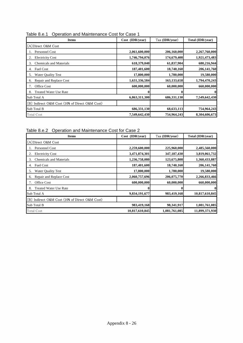
Appendix 8 - 26
Table 8.e.1 Operation and Maintenance Cost for Case 1 Cost (IDR/year) Tax (IDR/year) Total (IDR/year)
〔A〕Direct O&M Cost
1. Personnel Cost 2,061,600,000 206,160,000 2,267,760,000
2. Electricity Cost 1,746,794,076 174,679,408 1,921,473,483
3. Chemicals and Materials 618,379,040 61,837,904 680,216,944
4. Fuel Cost 187,401,600 18,740,160 206,141,760
5. Water Quality Test 17,800,000 1,780,000 19,580,000
6. Repair and Replace Cost 1,631,336,584 163,133,658 1,794,470,243
7. Office Cost 600,000,000 60,000,000 660,000,000
8. Treated Water Use Rate 0 0 0
Sub Total A 6,863,311,300 686,331,130 7,549,642,430
〔B〕 Indirect O&M Cost (10% of Direct O&M Cost)
Sub Total B 686,331,130 68,633,113 754,964,243
Total Cost 7,549,642,430 754,964,243 8,304,606,673
Items
Table 8.e.2 Operation and Maintenance Cost for Case 2
Cost (IDR/year) Tax (IDR/year) Total (IDR/year)
〔A〕Direct O&M Cost
1. Personnel Cost 2,259,600,000 225,960,000 2,485,560,000
2. Electricity Cost 3,471,874,301 347,187,430 3,819,061,732
3. Chemicals and Materials 1,236,758,080 123,675,808 1,360,433,887
4. Fuel Cost 187,401,600 18,740,160 206,141,760
5. Water Quality Test 17,800,000 1,780,000 19,580,000
6. Repair and Replace Cost 2,060,757,696 206,075,770 2,266,833,466
7. Office Cost 600,000,000 60,000,000 660,000,000
8. Treated Water Use Rate 0 0 0
Sub Total A 9,834,191,677 983,419,168 10,817,610,845
〔B〕 Indirect O&M Cost (10% of Direct O&M Cost)
Sub Total B 983,419,168 98,341,917 1,081,761,085
Total Cost 10,817,610,845 1,081,761,085 11,899,371,930
Items

Appendix 8 - 27
Table 8.e.3 Personnel Cost (1) Case 1
Numbers
Total
Director 1 33,000,000 396,000,000
Deputy Director 1 22,000,000 264,000,000
Secretary 1 5,500,000 66,000,000
Sub Total 3 726,000,000
Manager 1 15,000,000 180,000,000
Administration Secretary 1 5,500,000 66,000,000
Administration Staff 2 5,500,000 132,000,000
Security Staff 3 1,500,000 54,000,000
Office Boy 1 1,000,000 12,000,000
Sub Total 8 444,000,000
Manager 1 16,300,000 195,600,000
Engineer/Operator 9 5,500,000 594,000,000
Chemist 1 8,500,000 102,000,000
Sub Total 11 891,600,000
Total 22 2,061,600,000
Management
Admini & Finance
Treatment Plantand Pipe FacilityTechnical Staff
Unit Price(IDR/Staff/month)
Annual Total(IDR)
(2) Case 2
Numbers
Total
Director 1 33,000,000 396,000,000
Deputy Director 1 22,000,000 264,000,000
Secretary 1 5,500,000 66,000,000
Sub Total 3 726,000,000
Manager 1 15,000,000 180,000,000
Administration Secretary 1 5,500,000 66,000,000
Administration Staff 2 5,500,000 132,000,000
Security Staff 3 1,500,000 54,000,000
Office Boy 1 1,000,000 12,000,000
Sub Total 8 444,000,000
Manager 1 16,300,000 195,600,000
Engineer/Operator 12 5,500,000 792,000,000
Chemist 1 8,500,000 102,000,000
Sub Total 14 1,089,600,000
Total 25 2,259,600,000
Admini & Finance
Treatment Plantand Pipe FacilityTechnical Staff
Management
Annual Total(IDR)
Unit Price(IDR/Staff/month)

Appendix 8 - 28
Table 8.e.4 Electricity Cost (Case 1) total running total running Daily Annual Annual
power unit power unit power hour load Electricity Electricity Electricity
[kW] [unit] [kW] [unit] [kW] [h/day] (%) use (kWh) use (kWh) cost (IDR.)
BAR SCREEN 0.1 1 0.1 1 0.1 24.0 80 1.92 701 525,600
RAW WATER PUMP 30 2 60 1 30 24.0 80 576 210,240 157,680,000
STRAINER 0.75 1 0.75 1 0.75 24.0 80 14.4 5,256 3,942,000
BIOLOGICAL FILTER PUMP 15 2 30 1 15 24.0 80 288 105,120 78,840,000
BLOWER 29.2 2 58.4 1 29.2 24.0 80 560.64 204,634 153,475,200
BACKWASH BLOWER 47.2 2 94.4 1 47.2 0.1 80 4.5312 1,654 1,240,416
BACKWASH PUMP 45 3 135 2 90 0.1 80 8.64 3,154 2,365,200
OZONE REACTOR PUMP 30 2 60 1 30 24.0 80 576 210,240 157,680,000
OZONE GENERATOR 38 1 38 1 38 24.0 68 620.16 226,358 169,768,800
O2 PSA 0.1 1 0.1 1 0.1 24.0 90 2.16 788 591,300
AIR COMPRESSOR 55 1 55 1 55 24.0 65 858 313,170 234,877,500
CHILLER UNIT 48 1 48 1 48 24.0 76 875.52 319,565 239,673,600
OZONE TREATMENT UNIT(FOR OZONE UNIT) 1.25 1 1.25 1 1.25 24.0 80 24 8,760 6,570,000
AGITATOR (PH ADJUST) 2.2 1 2.2 1 2.2 24.0 80 42.24 15,418 11,563,200
AGITATOR (RAPID) 2.2 1 2.2 1 2.2 24.0 80 42.24 15,418 11,563,200
AGITATOR (SLOW) 2.2 1 2.2 1 2.2 24.0 80 42.24 15,418 11,563,200
COAGULANT FEED PUMP 0.02 2 0.04 1 0.02 24.0 65 0.312 114 85,410
PH MODIFIER PUMP (ACID INJECTION) 0.03 2 0.06 1 0.03 24.0 65 0.468 171 128,115
MEMBRANE FILTER PUMP 30 2 60 1 30 24.0 80 576 210,240 157,680,000
OZONE TREATMENT UNIT 3 1 3 1 3 24.0 80 57.6 21,024 15,768,000
COAGULANT TANK BLOWER 2.2 1 2.2 1 2.2 24.0 80 42.24 15,418 11,563,200
AIR COMPRESSOR 15 2 30 1 15 0.9 80 11.28 4,117 3,087,900
WATER SUPPLY PUMP UNIT 3.7 1 3.7 1 3.7 16.0 80 47.36 17,286 12,964,800
HYPOCHLORITE FEED PUMP 0.03 2 0.06 1 0.03 0.2 65 0.002925 1 801
ACID FEED PUMP 0.2 2 0.4 1 0.2 0.5 80 0.08 29 21,900
CHEMICAL CLEANING PUMP 1.2 2 2.4 2 2.4 - 80 0 ≒0 ≒0
CHEMICAL PULLING PUMP 1.5 2 3 2 3 - 80 0 ≒0 ≒0
THIOSULFURIC ACID PUMP 0.02 2 1 1 0.02 2.3 80 0.0368 13 10,074
SODIUM HYDROXIDE PUMP 0.02 2 0.04 1 0.02 7.0 80 0.112 41 30,660
DRAINAGE PUMP 11 2 22 1 11 6.0 80 52.8 19,272 14,454,000
TRANSMISSION PUMP 55 2 110 1 55 24.0 80 1056 385,440 289,080,000
Total 6,381 2,329,059 1,746,794,076
※Connection fee to Electric Power Company (631,250,000 IDR) is added on fist year.
750 IDR/kWh = Unit rate of electricityTotal Electricity Cost = (IDR/ year)1,746,794,076
Table 8.e.5 Chemicals Cost (Case 1)
Used Amount Chemical Cost/Kg Annual cost
(kg/day) usage rate (IDR) (IDR)
Coagulant (PACL) 540.0 0.5 4,348 428,495,400
Acid (pH) 92.7 0.5 2,717 45,965,527
Acid (Backwash) 47.0 0.5 2,717 23,305,068
Sodium Hydroxide 115.0 0.5 3,261 68,440,238
Hypochlorite 12.0 0.5 7,609 16,663,710
Thiosulfuric Acid 2.6 0.5 16,304 7,736,248
Hypochlorite (for Disinfection) 20.0 0.5 7,609 27,772,850
Total 618,379,040

Appendix 8 - 29
Table 8.e.6 Electricity Cost (Case 2) total running total running Daily Annual Annual
power unit power unit power hour load Electricity Electricity Electricity
[kW] [unit] [kW] [unit] [kW] [h/day] (%) use (kWh) use (kWh) cost (IDR.)
BAR SCREEN 0.1 2 0.2 1 0.1 24.0 80 1.92 701 525,600
RAW WATER PUMP 30 3 90 2 60 24.0 80 1152 420,480 315,360,000
STRAINER 0.75 2 1.5 2 1.5 24.0 80 28.8 10,512 7,884,000
BIOLOGICAL FILTER PUMP 15 3 45 2 30 24.0 80 576 210,240 157,680,000
BLOWER 29.2 3 87.6 2 58.4 24.0 80 1121.28 409,267 306,950,400
BACKWASH BLOWER 47.2 2 94.4 1 47.2 0.1 80 4.5312 1,654 1,240,416
BACKWASH PUMP 45 3 135 2 90 0.1 80 8.64 3,154 2,365,200
OZONE REACTOR PUMP 30 3 90 2 60 24.0 80 1152 420,480 315,360,000
OZONE GENERATOR 38 2 76 2 76 24.0 68 1240.32 452,717 339,537,600
O2 PSA 0.1 2 0.2 2 0.2 24.0 90 4.32 1,577 1,182,600
AIR COMPRESSOR 55 2 110 2 110 24.0 65 1716 626,340 469,755,000
CHILLER UNIT 48 2 96 2 96 24.0 76 1751.04 639,130 479,347,200
OZONE TREATMENT UNIT(FOR OZONE UNIT) 1.25 2 2.5 2 2.5 24.0 80 48 17,520 13,140,000
AGITATOR (PH ADJUST) 2.2 2 4.4 2 4.4 24.0 80 84.48 30,835 23,126,400
AGITATOR (RAPID) 2.2 2 4.4 2 4.4 24.0 80 84.48 30,835 23,126,400
AGITATOR (SLOW) 2.2 2 4.4 2 4.4 24.0 80 84.48 30,835 23,126,400
COAGULANT FEED PUMP 0.02 3 0.06 2 0.04 24.0 65 0.624 228 170,820
PH MODIFIER PUMP (ACID INJECTION) 0.03 3 0.09 2 0.06 24.0 65 0.936 342 256,230
MEMBRANE FILTER PUMP 30 3 90 2 60 24.0 80 1152 420,480 315,360,000
OZONE TREATMENT UNIT 3 3 9 2 6 24.0 80 115.2 42,048 31,536,000
COAGULANT TANK BLOWER 2.2 2 4.4 2 4.4 24.0 80 84.48 30,835 23,126,400
AIR COMPRESSOR 15 2 30 1 15 0.9 80 11.28 4,117 3,087,900
WATER SUPPLY PUMP UNIT 3.7 2 7.4 2 7.4 16.0 80 94.72 34,573 25,929,600
HYPOCHLORITE FEED PUMP 0.03 3 0.09 2 0.06 0.2 65 0.00585 2 1,601
ACID FEED PUMP 0.2 3 0.6 2 0.4 0.5 80 0.16 58 43,800
CHEMICAL CLEANING PUMP 1.2 2 2.4 2 2.4 - 80 0 ≒0 ≒0
CHEMICAL PULLING PUMP 1.5 2 3 2 3 - 80 0 ≒0 ≒0
THIOSULFURIC ACID PUMP 0.02 2 1 1 0.02 2.3 80 0.0368 13 10,074
SODIUM HYDROXIDE PUMP 0.02 2 0.04 1 0.02 7.0 80 0.112 41 30,660
DRAINAGE PUMP 11 2 22 1 11 6.0 80 52.8 19,272 14,454,000
TRANSMISSION PUMP 55 3 165 2 110 24.0 80 2112 770,880 578,160,000
Total 12,683 4,629,166 3,471,874,301
750 IDR/kWh = Unit rate of electricityTotal Electricity Cost = (IDR/ year)3,471,874,301
Table 8.e.7 Chemicals Cost (Case 2)
Used Amount Chemical Cost/Kg Annual cost
(kg/day) usage rate (IDR) (IDR)
Coagulant (PACL) 540.0 1 4,348 856,990,800
Acid (pH) 92.7 1 2,717 91,931,054
Acid (Backwash) 47.0 1 2,717 46,610,135
Sodium Hydroxide 115.0 1 3,261 136,880,475
Hypochlorite 12.0 1 7,609 33,327,420
Thiosulfuric Acid 2.6 1 16,304 15,472,496
Hypochlorite (for Disinfection) 20.0 1 7,609 55,545,700
Total 1,236,758,080

Appendix 8 - 30
Table 8.e.8 Fuel Cost (Case 1 or Case 2) For Vehicles Diesel fuel Unit Price = 6,000 IDR/liter
No of days/ Fuel Consumption Working Time Unit cost/ Unit cost/ No of Total cost
year (liter/hours) (hours/day) (IDR/liter) day* sets (IDR/year)
Patrol Car 150 2.6 6 4,500 84,240 1 12,636,000
Tanker Truck 225 5.3 6 6,000 228,960 2 103,032,000
Others (20%) 23,133,600
Total 138,801,600
*Unit cost is including lubricant cost (20%)
For Standby Generator (for maintenance operation)
Capacity Unit Consumption Working Time Unit cost/ Unit cost/ No of Total cost
(kVA) (liter/kVA/hour) (hours/month) (IDR/liter) day* sets (IDR/year)
Treatment Plant 750 0.25 6 6,000 8,100,000 6 48,600,000
Total cost (IDR/year) = 187,401,600

Appendix 8 - 31
Table 8.e.9 Water Quality Test Cost (Case 1 or Case 2)
(a) Monthly(b)Semiannua
lA. Physical Parameter
1) Smell 3,500 3,500 3,500
2) Floating Objects 5,000 5,000 5,000
3) Clarity 5,000 5,000 5,000
4) Color TCU 20,000 20,000 20,000
5) Oil mg/l 5,000 5,000 5,000
6) Turbidity NTU 15,000 15,000 15,000
7) TDS mg/l 17,500 17,500
B. Chemical Parameter
1) Al mg/l 50,000 50,000
2) Hardness mg/l 15,000 15,000 15,000
3) Oxygen absorbed (O2) mg/l 15,000 15,000 15,000
4) pH 5,000 5,000 5,000
5) Residual Chlorine mg/l 15,000 15,000 15,000
6) Cu mg/l 40,000 40,000
7) Detergent (MBAS) mg/l 50,000 50,000
8) BOD mg/l 30,000 30,000 30,000
9) Dissolved Oxygen (O2) mg/l 15,000 15,000 15,000
10) As mg/l 50,000 50,000
11) F mg/l 25,000 25,000
12) Cr mg/l 40,000 40,000
13) Cd mg/l 40,000 40,000
14) Nitrite (NO2) mg/l 25,000 25,000
15) Nitrite (NO3) mg/l 25,000 25,000
16) CN mg/l 25,000 25,000
17) Se mg/l 40,000 40,000
18) Fe mg/l 40,000 40,000
19) Mn mg/l 40,000 40,000
20) Zn mg/l 40,000 40,000
21) SO4 mg/l 25,000 25,000
22) Ammonia (NH3) mg/l 25,000 25,000
C. Microbiological Parameters
1) Total Coliform CFU/100ml 42,000 42,000 42,000
2) Number of Germs Colonies/ml 42,000 42,000 42,000
232,500 830,000
232,500 830,000
24 4
11,160,000 6,640,000
(a)+(b) 17,800,000
Water Sample per year
Total Cost
Other Cost (100%)
Measurement Item
Cost for 1 Set
No. Item Unit Cost

Appendix 8 - 32
Table 8.e.10 Repair and Replace Cost (1) Case 1 A. Site Preparation
Capital Cost(1,000IDR) (IDR/year)
Structure 5,968,887 0.10% 5,968,887Total 5,968,887 5,968,887
B. Reclaimed Water Treatment FacilityCapital Cost(1,000IDR) (IDR/year)
Structure 30,427,382 0.10% 30,427,382Vehicles 2,070,000 3.00% 62,100,000Equipment 87,646,381 1.50% 1,314,695,715Membrane Replacement 174,000 100% 174,000,000Total 120,143,763 1,581,223,097
C. Water Transmission PipeCapital Cost(1,000IDR) (IDR/year)
Structure 44,144,600 0.10% 44,144,600Total 44,144,600 44,144,600
Case1 Cost 1,631,336,584 IDR/year
Annual repair and maintenance cost% of Capital Cost
Annual repair and maintenance cost% of Capital Cost
Annual repair and maintenance cost% of Capital Cost
(2) Case 2 A. Site Preparation
Capital Cost(1,000IDR) (IDR/year)
Structure 6,507,139 0.10% 6,507,139Total 6,507,139 6,507,139
B. Reclaimed Water Treatment FacilityCapital Cost(1,000IDR) (IDR/year)
Structure 38,054,721 0.10% 38,054,721Vehicles 2,070,000 3.00% 62,100,000Equipment 103,325,176 1.50% 1,549,877,636Membrane Replacement (1) 174,000 100% 174,000,000Membrane Replacement (2) 174,000 100% 174,000,000Total 143,449,897 1,998,032,357
C. Water Transmission PipeCapital Cost(1,000IDR) (IDR/year)
Structure 56,218,200 0.10% 56,218,200Total 56,218,200 56,218,200
Case2 Cost = 2,060,757,696 IDR/year
Annual repair and maintenance cost% of Capital Cost
Annual repair and maintenance cost% of Capital Cost
Annual repair and maintenance cost% of Capital Cost
APPENDIX 9
DETAILED PROJECT ACTIVITY
PLAN

Appendix 9 - 1
APPENDIX 9 DETAILED PROJECT ACTIVITY PLAN This appendix is prepared as the Detailed Project Activity Plan requested in the Minutes of Meetings signed between the Indonesian government and JICA on December 1, 2010. This appendix can be referred as well as Appendix 11 (A Draft TOR for the EIA) in the preparation of the draft KA-ANDAL for this project. The following descriptions of the proposed project activities (i.e. Scope of Work) are prepared mainly in accordance to the Regulation of Ministry of Environment (No.8/2006) on Guideline of EIA Preparation. 9.a Background of the Project Bali is one of the famous tourist spots in Asia. The regional economy in Bali relies on its tourism industry and agriculture of wet-rice cultivation. Denpasar City and Badung Regency located in Southern Bali are developing as a center of tourism and commerce and their population is increasing rapidly. The growth in economic and population is increasing water demand and causing water shortage. However, the development of water supply systems in Bali is left behind the growth in economic and population. Water shortage and river water pollution are disturbing the sustainable economic development in Bali. Groundwater has been used for mitigating the water shortage. However, its overuse caused the salination and depletion of groundwater in the coastal areas of Southern Bali. These difficult situations in groundwater use have recently become obvious. On the other hand, Denpasar Sewerage Development Project is been implemented by Japanese ODA loan in Denpasar City and its surrounding areas having high population density. The collected wastewater is being treated at Suwung WWTP. The treated wastewater from the WWTP is an important water resource which can be recycled. In order to reduce the water shortage in Southern Bali and mitigate the groundwater salination and depletion, effective uses of the treated wastewater from Suwung WWTP have been studied by Indonesian government agencies. However any reclaimed water project using the treated wastewater has not been realized due to financial difficulties. In these circumstances, a Japanese joint venture (consisting of Toyota Tsusho Corporation, Nihon Suido Consultants Co. Ltd, and METAWATER Co. Ltd) have proposed to JICA to study the possibility of formulating a reclaimed water supply project in Southern Bali as a Public-Private Partnership (referred as PPP) Project. In response, JICA commissioned this preparatory survey to the joint venture at the end of 2010 in order to formulate a feasible reclaimed water supply project in Southern Bali. 9.b Objectives and Benefits of the Project The objectives of the reclaimed water supply project proposed in the preparatory survey are as follows: 1) To utilize the treated wastewater from Suwung WWTP for producing reclaimed water with
suitable quality for showering, bathing and pool 2) To supply the reclaimed water to the hotels in Nusa Dua, Sawangan, Benoa where water
shortage and overuse of groundwater are serious 3) To make the PDAM water more available to the domestic customers in the service areas of
Estuary Water Purification Plant The objects of this project are also explained in 7.1 of the main report. The main benefits of this project are as follows: a) The reduction of the effluent from Suwung WWTP which have negative impacts on the environment
around its discharge point.

Appendix 9 - 2
b) The mitigation of the serious water shortage in the service areas of Estuary Water Purification Plant, which will contribute to:
i. the improvement of the targeted hotels and the development of new hotels in the target areas of the project;
ii. the reduction of the excessive extraction of groundwater in the targeted hotels and the new hotels; and
iii. the increase of drinking/clean water available for the domestic users. c) The establishment of local experiences regarding wastewater reclamation, which will be important for
the formulation of other reclaimed water supply projects in Indonesia in the future. The results of the economic analysis on the project including the evaluation of these benefits are explained in Chapter 13 of the main report. These benefits are also explained as the positive impacts of the project in the environmental scooping (see 10.4.3 of the main report and 10.c of Appendix 10). 9.c Scope of the Project and Alternative Project Components The proposed scope of the project is explained in 7.2 to 7.4 of the main report. Although the route of the transmission pipeline along the existing main road (Ngurah Rai By-pass Road) was selected in this preparatory survey, the alternative analysis on the route of the transmission pipeline (see 10.b (3) of Appendix 10) should be reviewed in the EIA and the detailed design study in order to mitigate the traffic congestion to be caused by the pipe installation. Moreover, it is not yet confirmed that the proposed wastewater reclamation facilities can meet the existing Indonesian water quality standards for pool and public bath continuously. The size of the biological filter for the pretreatment may need to be larger than its proposed design if the existing water quality standards cannot be continuously met with the proposed design. In case that new Indonesian water quality standards for reclaimed water is established before the implementation of the detained design study and the EIA, the wastewater reclamation facilities should be re-designed based on the new water quality standards. The ratio of mixing the reclaimed water with the PDAM water at the target hotels may also be revised in the detailed design study based on the results of the reclaimed water demand confirmation to be conducted before the signing of the PPP contract. 9.d Maps and Social and Environmental Descriptions of the Project Sites Figures 9.d.1 to 9.d.5 shows the overall layout of the facilities related to the project including the tentative route of the transmission pipeline, the site plan of the proposed water reclamation plant, and the routes of the existing trunk distribution pipes in Nusa Dua and new trunk distribution pipes to Benoa and Sawangan. Detail maps of the route for the transmission pipeline are shown in 6.c of Appendix 6. The proposed site for the wastewater reclamation plant is located at the edge of Ngurah Rai Mangrove Forest Area which is owned by the Ministry of Environment as shown in Figure 9.d.2. The land use in this area is controlled by the ministry through a land use permission process. The Forestry Agency of Bali Provincial Government is in charge of the forestry management in this area. Nusa Dua has many new large resort hotels. Benoa has some large resort hotels and many middle size hotels and small villas. New large resort hotels are currently under construction in Sawangan. General natural conditions and socio-economic conditions of Bali Island are also described in 2.1 and 2.2 of the main report. 9.e Project Activities from Pre-Construction Stage to Post-Operation Stage Section 9.7 of the main report shows the implementation schedule of the project.

Appendix 9 - 3
The project activates in each stage of the project are explained in the following, which are in consistency with those listed in the comprehensive environmental scoping matrix (see Table 10.c.1 of Appendix 10). (1) Pre-Construction Stage In the pre-construction stage of the project, several types of permissions and agreements are required before starting the construction, which include the land use permit from the Ministry of Forestry, the PPP contract, the purchase agreement with PDAM Badung, the approvals on KA-ANDAL and the EIA documents, etc. The project also needs a further survey for confirming the targeted hotels’ demand on the reclaimed water. The feasibility of the project has to be also examined by a PPP team from the Indonesian/Balinese side in the pre-construction stage. 1. Acquisition of Land Use Permit
DINAS PU/Bali Provincial Government needs to acquire the land use permit from the Ministry of Forestry (in coordination with the Forestry Agency of Bali Provincial Government) for using the land of the proposed water reclamation plant site.
2. Acquisition of Other Approvals and Agreements The project needs a PPP contract with Bali Provincial Government and a purchase agreement with PDAM Badung. New reclaimed water standards (if necessary) and new tariffs for the reclaimed water supply may needs to be prepared before the signing of the PPP contract. The project also needs approval on the draft KA-ANDAL and the final EIA documents. The permissions to use the treated wastewater and to supply the reclaimed water should be included in these approvals and agreements.
3. Study and Field Survey
More studies and filed surveys are required for the EIA, the detailed design, the confirmation of reclaimed water demand in the target hotels, the confirmation of achievable water quality and the establishment of new reclaimed water quality standards (if necessary).

App
endi
x 9
- 4
F
igur
e 9.
d.1
Ove
rall
Layo
ut o
f the
Fac
ilitie
s re
late
d to
the
Pro
ject
New
Tra
nsm
issi
on P
ipel
ine
(φ40
0 H
DP
E)
Exi
stin
g D
istr
ibu
tion
Net
wor
k in
Nu
sa D
ua
(av
aila
ble
for
th
e re
clai
med
wat
er s
up
ply
)
1st
Ph
ase:
4,5
00m
3 /d
2nd
Ph
ase:
4,5
00m
3 /d
Pro
pos
ed W
aste
wat
er R
ecla
mat
ion
Pla
nt
New
Tru
nk
Dis
trib
uti
on M
ain
to
Ben
oa
New
Tru
nk
Dis
trib
uti
on M
ain
to
Saw
anga
nE
xist
ing
UPA
Res
ervo
ir (
1,50
0m3 )
Su
wu
ng
WW
TP

App
endi
x 9
- 5
F
igur
e 9.
d.2
Site
Pla
n fo
r th
e P
ropo
sed
Wat
er R
ecla
mat
ion
Pla
nt
Wat
er R
ecla
mat
ion
P
lan
t(1
0h
a)
Pro
po
sed
Lay
ou
t o
f W
ater
Rec
lam
atio
nP
lan
t
Raw
Wat
er
Pu
mp
Sta
tio
n
Fu
ll-sc
ale
Wat
erR
ecla
mat
ion
Pla
nt
Pro
pose
d W
aste
wat
er
Rec
lam
atio
n P
lant
Den
pasa
r W
aste
wat
er
Tre
atm
ent P
lant
(W
WT
P)
Suw
ung
WW
TP
Tra
nsm
issi
on P
ipe
for
the
Rec
laim
ed W
ater
Pro
pose
d W
aste
wat
er
Rec
lam
atio
n P
lant
Suw
ung
WW
TP
Pip
e fo
r re
turn
ing
the
used
ba
ckw
ash
wat
er fr
om th
e w
ast
ew
ater
rec
lam
atio
n pl
ant
toth
ein
let
ofth
eW
WT
P
Zoo
m U
p

App
endi
x 9
- 6
F
igur
e 9.
d.3
Exi
stin
g D
istr
ibut
ion
Net
wor
k in
Nus
a D
ua a
vaila
ble
for
the
Rec
laim
ed W
ater
Sup
ply
Clu
b M
edit
erra
nee
Nov
otel
Nus
a D
ua G
olf
Res
ort

App
endi
x 9
- 7
F
igur
e 9.
d.4
New
Dis
trib
utio
n P
ipes
to B
enoa
Mel
ia B
enoa
BD
C

App
endi
x 9
- 8
F
igur
e 9.
d.5
New
Dis
trib
utin
g P
ipes
to S
awan
gan
BD
C
Sw
iss
Gra
nd
Mul
ia R
esor
t
NUSA DUA

Appendix 9 - 9
4. Public Consultation and Socialization Public consultation and socialization are required for 1) the transaction of this PPP project (See 14.3.2 of the main report), 2) the establishment of new water quality standards for reclaimed water (if necessary), 3) the establishment of new tariffs for the reclaimed water supply, 5) the approval on the EIA documents, and 6) the start of construction at each project site (as planned in the environmental management plan).
(2) Construction Stage The construction stage includes personal mobilization, base camp operation, material/equipment mobilization, construction works, equipment demobilization and personal demobilization. The construction works can be divided to those for the new wastewater reclamation plant and the existing distribution reservoir and those for the installation of transmission, distribution and service pipes. The construction works for the new wastewater reclamation plant can be further divided into land clearing, excavation/embankment, building the structures/installation of equipment and landscaping. 1. Personal Mobilization
The SPC needs to establish a construction management team and need to make contracts with local sub-contractors.
2. Base Camp Operation
A based camp needs to be established by lending office and accommodations or constructing prefabrication buildings. Utilities and office appliances needs to be ready to use in the base camp.
3. Material/Equipment Mobilization
Materials and equipment required for the construction works need to be brought close to the construction sites.
4. Land Clearing
The mangrove trees at the proposed site for the wastewater reclamation plant needs to be removed. 5. Land Excavation/Embankment
The construction of the new wastewater reclamation plant requires the excavation of unstable surface soil after the removable of mangrove trees. Then, the site should be embanked up to the base ground level of the existing WWTP with stable soil for the construction. Soil excavation is also required to the construction of the new raw water pumping station for the wastewater reclamation within the existing WWTP.
6. Building of Structures/Installation of Equipment
The proposed wastewater purification plant consists of several buildings for raw water transmission, biological treatment, ozone treatment, membrane treatment, chlorination, treated water transmission, etc.
7. Landscaping

Appendix 9 - 10
The main gate and the buildings of the wastewater purification plant should follow building code regulations of Bali.
8. Installation of Pipe Facilities
In order to supply the reclaimed water to the targeted areas, it is required to install 1) a transmission pipeline from the wastewater reclamation plant to the existing distributing reservoir in Nusa Dua, 2) two trunk distribution pipelines from the distribution reservoir to Benoa and Sawangan, and 3) service pipes from the existing distribution pipes in Nusa Dua and the new distribution pipes in Benoa and Sawangan to each hotel in the target areas. The rehabilitation of the existing distribution pipes in Nusa Dua and the installation of the new distribution pipes and service pipes are part of the responsibility of PDAM Badung according to the plan proposed in the preparatory survey.
9. Equipment Demobilization
Equipment used in the construction is removed from the construction sites.
10. Personal Demobilization
The construction workers need to move out of the base camp. (3) Operation Stage The operation stage of this project includes the personal mobilization of SPC and PDAM Badung, the operation and maintenance of reclaimed water treatment facilities (including the operation of pumps and valves for raw water intake, transmission and distribution and the maintenance of the pipes), meter reading, billing & revenue collection and customer services. The main components of the operation stage are explained as follows: 1. Personal Mobilization
SPC needs to mobilize operational staff at the wastewater reclamation plant and PDAM Budung needs to assign O&M and administration tasks for the retail supply of the reclaimed water to their existing or new staff.
2. Water Treatment Operation
The proposed treatment process for the wastewater reclamation includes the use of biological filter, pre-zonation, coagulation/flocculation, ceramic membrane and chlorination. The residual ozone after the pre-zonation is removed at the wastewater reclamation plant.
3. Backwash Water Management
The biological filter and ceramic membrane needs to be backwashed regularly. It is planned to send back the used backwash water to the inlet of the WWTP. Therefore, no sludge will be generated from the used backwash water in the wastewater reclamation plant.
4. Rotating Machinery Operation
In addition to the pumps for raw water intake, the pumps for water transmission and water distribution, the blowers for the diffuser of biological filters and the feed pump for ceramic membrane need to be operated continuously. The operation of power generator is also required during power failures.

Appendix 9 - 11
5. Reclaimed Water Supply and Use
The reclaimed water will be transmitted and sold by the SPC as bulk water to PDAM Badung at the existing reservoir in Nusa Dua that was used for irrigation water in the past. PDAM Badung will be in charge of the reclaimed water distribution to the hotels in the target areas and billing & collection. The hotels can deliver the reclaimed water with the existing pipes inside the hotels to each guest room after mixing it with PDAM’s drinking/clean water.
6. Pipe Maintenance
All the pipes used for the reclaimed water supply requires maintenance to reduce leakage of the reclaimed water. The maintenance work is also required to avoid water quality degradation in the pipes.
7. Office Management
The office for management and administration staff and the workshop and resting place for technical staff need to be maintained.
8. Tariff Collection
Reclaimed water charges will be collected from the hotels using the reclaimed water, based on their consumptions of the reclaimed water measured with water meters. PDAM Badung will be in charge of the tariff collection.
(4) Post-Operation Stage Since this project is planned as a BOT of 25 years. The facilities to be constructed for the project will be handed over to Bali Provincial Government 25 years after the signing of PPP contract. The machinery and electrical equipment to be installed will reach its lifetime expectancy at the time of handing over. In order to continue the reclaimed water service, the replacement of the machineries and electrical equipment are required. After the cease of the operation, land rehabilitation and personal demobilization are required as explained in the following. 1. Land Rehabilitation
After the cease of the operation, the land for the water reclamation plant needs to be rehabilitated before being returned to the Ministry of Forestry.
2. Personal Demobilization
The staff working exclusively for the project may need support to find new jobs.