The Potential of Lime and Grand Granulated Blast Furnace Slag...
12
Journal of Civil Engineering Research 2012, 2(6): 108-119 DOI: 10.5923/j.jce.20120206.07 The Potential of Lime and Grand Granulated Blast Furnace Slag (GGBFS) Mixture for Stabilisation of Desert Silty Sands Parham Rabbani 1,* , Younes Daghigh 2 , Mohammad Reza Atrechian 1 , Masoud Karimi 3 , Ali Tolooiyan 4 1 Dept of Civil Engineering, AZAD University, ZANJAN, 45156-58145, Iran 2 Dept of Civil Engineering, AZAD University, KARAJ, 31485-313, Iran 3 Dept of Civil Engineering, GUILAN University, GUILAN, 1841, Iran 4 Geotechnical and Hydrogeological Engineering Research Group (GHERG), MONASH University, Victoria, Australia Abstract This study describes experimental results achieved on the use of Grand Granulated Blast Furnace Slag (GGBFS) and Lime in stabilising desert silty sand for possible use in geotechnical engineering applications, especially for roadways and railways constructions. The GGBFS and lime were added in percentages of 5, 10 and 15% and 1, 3, and 5% respectively, by dry weight of sand. Different laboratory tests such as mechanical aggregation test, hydrometer analysis, liquid-plastic limit, pH value test, compaction, unconfined compressive strength (UCS), California bearing ratio test CBR , were performed on samples to understand the engineering characteristic of soil and influences of mixtures on the silty sand soil. The study results demonstrate significant improvements in unconfined compressive strength and California bearing ratio strength. Moreover the swelling behaviour of mixtures was decreased effectively. Thus mixture of GGBFS and lime can be suggested to improve engineering characteristic of desert silty sands. Keywords DesertSilty Sand, Stabilisation, Slag, Lime, CBR, UCS 1. Introduction Nowadays faster transportation and saving more energy has undeniable role on development of societies. In countries with large desert areas, expansion of roadways and railways and preparing suitable construction materials is one of the main technical and economical engineering challenges. Desert sands are usually fine-grained and poorly graded materials with small amounts of silt[1]. Desert sands are not suitable for support of structures and roads, because they are loose and vulnerable to collapse upon wetting[2]. Low bearing capacity, strength, stiffness and high porosity of this type of soils cusses excessive settlement and severe damages to roadways and railways constructions. Also preparing and transporting proper construction material from other areas forces excessive costs on project and is not economical. There are several methods for improving the strength of soils and one of the most effective methods is soil stabilisation. Various methods of soil stabilisation, such as, * Corresponding author: [email protected] (Parham Rabbani) Published online at http://journal.sapub.org/jce Copyright © 2012 Scientific & Academic Publishing. All Rights Reserved use of cement[3, 4, 5, 1], cement-by-pass dust[6, 7, 5], bentonite[8], coal fly ash[9, 10, 11], asphalt[12], and lime[13], re-enforcement of sand by fibres are reported[14, 15, 11]. This paper describes a laboratory study conducted to evaluate, the potential of improving the engineering properties of loose desert sands of Iran (JANDAGH- GARMSAR) by using Grand Granulated Blast Furnace Slag (GGBFS) and lime as an admixture. Various mineralogical and geotechnical laboratory tests were performed on untreated soil and soil-GGBFS-lime mixtures. In order to achieve the appropriate mixture, different percentages of GGBFS and lime have been mixed and the properties of the untreated soil and mixtures, such as Unconfined Compressive Strength (UCS), California Bearing Ratio (CBR), and swelling potential were evaluated and finally tests results were compared. 2. Background Incineration of MunicipalSolid Waste (MSW) is a common practice to reduce the volume of the waste to be disposed in a landfill[1].Regarding to existence of numerous iron and steel smelting factories in Iran, one of the materials which incineration process produces are different kinds of slag like (GGBFS) that can further be utilized in construction
Transcript of The Potential of Lime and Grand Granulated Blast Furnace Slag...
Journal of Civil Engineering Research 2012, 2(6): 108-119
DOI: 10.5923/j.jce.20120206.07
The Potential of Lime and Grand Granulated Blast
Furnace Slag (GGBFS) Mixture for Stabilisation of Desert
Silty Sands
Parham Rabbani1,*
, Younes Daghigh2, Mohammad Reza Atrechian
1, Masoud Karimi
3, Ali Tolooiyan
4
1Dept of Civil Engineering, AZAD University, ZANJAN, 45156-58145, Iran 2Dept of Civil Engineering, AZAD University, KARAJ, 31485-313, Iran 3Dept of Civil Engineering, GUILAN University, GUILAN, 1841, Iran
4Geotechnical and Hydrogeological Engineering Research Group (GHERG), MONASH University, Victoria, Australia
Abstract This study describes experimental results achieved on the use of Grand Granulated Blast Furnace Slag
(GGBFS) and Lime in stabilising desert silty sand for possible use in geotechnical engineering applications, especially for
roadways and railways constructions. The GGBFS and lime were added in percentages of 5, 10 and 15% and 1, 3, and 5%
respectively, by dry weight of sand. Different laboratory tests such as mechanical aggregation test, hydrometer analysis,
liquid -plastic limit , pH value test, compaction, unconfined compressive strength (UCS), California bearing rat io test CBR ,
were performed on samples to understand the engineering characteristic of soil and influences of mixtures on the silty sand
soil. The study results demonstrate significant improvements in unconfined compressive strength and Californ ia bearing ratio
strength. Moreover the swelling behaviour of mixtures was decreased effectively. Thus mixture of GGBFS and lime can be
suggested to improve engineering characteristic of desert silty sands.
Keywords DesertSilty Sand, Stabilisation, Slag, Lime, CBR, UCS
1. Introduction
Nowadays faster transportation and saving more energy
has undeniable role on development of societies. In
countries with large desert areas, expansion of roadways
and railways and preparing suitable construction materials
is one of the main technical and economical engineering
challenges.
Desert sands are usually fine-grained and poorly graded
materials with small amounts of silt[1]. Desert sands are not
suitable for support of structures and roads, because they
are loose and vulnerable to co llapse upon wetting[2]. Low
bearing capacity, s trength, stiffness and high porosity of
this type of soils cusses excessive settlement and severe
damages to roadways and railways constructions. Also
preparing and transporting proper construction material
from other areas forces excessive costs on project and is not
economical.
There are several methods for improving the strength of
so ils and one o f the most effect ive methods is so il
stabilisation. Various methods of soil stabilisation, such as,
* Corresponding author:
[email protected] (Parham Rabbani)
Published online at http://journal.sapub.org/jce
Copyright © 2012 Scientific & Academic Publishing. All Rights Reserved
use of cement[3, 4, 5, 1], cement-by-pass dust[6, 7, 5],
bentonite[8], coal fly ash[9, 10, 11], asphalt[12], and
lime[13], re-enforcement of sand by fibres are reported[14,
15, 11].
This paper describes a laboratory study conducted to
evaluate, the potential of improving the engineering
properties of loose desert sands of Iran (JANDAGH-
GARMSAR) by using Grand Granulated Blast Furnace Slag
(GGBFS) and lime as an admixture. Various mineralogical
and geotechnical laboratory tests were performed on
untreated soil and soil-GGBFS-lime mixtures. In order to
achieve the appropriate mixture, d ifferent percentages of
GGBFS and lime have been mixed and the properties of the
untreated soil and mixtures, such as Unconfined
Compressive Strength (UCS), Californ ia Bearing Rat io
(CBR), and swelling potential were evaluated and finally
tests results were compared.
2. Background
Incineration of MunicipalSo lid Waste (MSW) is a
common practice to reduce the volume of the waste to be
disposed in a landfill[1].Regarding to existence of numerous
iron and steel smelting factories in Iran, one of the materials
which incineration process produces are different kinds of
slag like (GGBFS) that can fu rther be utilized in construction
109 Journal of Civil Engineering Research 2012, 2(6): 108-119
activities. Blast Furnace Slag (BFS) is a non-metallic
co-product, produced in the process of iron and steel
production. Different forms of slag product are produced
depending on the method used to cool the molten slag. These
products include Air-Cooled Blast Furnace Slag (ACBFS),
expanded or foamed slag, pelletized slag, and granulated
blast furnace slag[16]. GGBFS form produces by cooling the
molten slag using high pressure water jets to cool it
rapidly .This method of cooling, results in produces of
granular product[17], and formation of sand size (o r frit-like)
fragments, usually with some friable clinker like material.
The physical structure and gradation of granulated slag
depends on the chemical composition of the slag, its
temperature at the time of water quenching, and the method
of production. When crushed or milled to very fine
cement-sized particles, GGBFS has cementit ious properties.
It primarily consists of silicates, alumina-silicates, and
calcium alumina-silicates[16]. GBFS used as a stabiliser has
latent hydraulic properties. This means that, similar
topozzolanic materials, the slag can form strength enhancing
products with calcium hydroxide (Ca [OH] 2). The difference
is that the slag contains rather more react ive lime. However,
the reaction rate of the slag itself is so slow as to be
negligible. Some form of activators is therefore
necessary[18]. Higgins[19],observed that GGBFS on its own
has only mild cementitious properties and lime (calcium
hydroxide) can provide the necessary alkali for activation.
The most commonly used activators to activate GGBFS are
lime, alkalis[20], calcium hydroxide, calcium sulphate,
ordinary Portland cement, sodium hydroxide, sodium
carbonate and sodium sulphate[21]. The use of GGBFS is
well established in many applications where it provides good
durability, high resistance to chloride penetration, resistance
to sulphate attack and protection against alkali silica
reaction[17]. For instance In South Africa, GGBFS act ivated
by lime, is a commonly used binder for soil stabilisation[22],
also blends of lime and GGBFS are frequently used in
Australia[23,24].
The earliest work in modern t imes on the use of lime in
road construction goes back to 1925 in the American state of
Missouri[25]. Lime stabilisation is one of the most
commonly applied soil strength improvement techniques.
Generally, addit ion lime to clayey soil increases the soil
strength to a certain limit, however adding excess lime tends
to decrease the strength[26]. This technique is widely used in
the sub-grade, sub-base and base layers of road
construction[27].
Lime is produced by burning limestone and it can be used
to treat soils in the form of, quicklime (CaO), hydrated lime
(Ca [OH] 2), o r lime slurry. Quicklime is manufactured by
chemically transforming calcium carbonate (CaCO3) into
calcium oxide. Hydrated lime is created when quicklime
chemically reacts with water, the hydrate can be reconverted
to quicklime by removing the water by heating it. It hydrated
lime that reacts with soil part icles and permanently
transforms them into a strong cementitiousmatrix[16]. The
reaction formula of quick lime and water is shown as below:
CaO (s) + H2O (l) ----->Ca (OH) 2 (1)
This reaction generates heat and the pH value increases to
approximately 12.5. It is a suitable condition for the
subsequent pozzolan icreactions[18]. Similar studies by
Mallela[28], showed above fact which results to soil
stabilisation. The pozzo lanic reactions occur between silica
and alumina with in the clay structure with lime and water to
form calcium silicate hydrate (C-S-H) and calcium
aluminates hydrate gels (C-A-H) which subsequently
crystallise to bind the structure together[29].
Ca (OH) 2 -----> Ca2+
+ 2(OH) - (2)
Ca2+
+ 2 (OH) - + SiO2 (Silica) -----> C-S-H (3)
Ca2+
+2 (OH) - + A l2O3 (Alumina) -----> C-A-H (4)
The most important reactions of lime with soil can divided
into four groups; (a) cation exchange; (b) flocculation and
agglomerat ion; (c) carbonation; and (d) pozzolanic reactions
[30,31,32], and the following changes are observed in the
soil in short term[27]: optimum water content values
increase, proctor densities decrease, plasticity indices reduce,
proctor curve levels out, unconfined compressive strength,
and CBR values increase. The use of lime stabilisation for
road constructions reduces the thickness of the upper layers
due to high CBR values and makes the overall construction
more economical[27]. In studies conducted by Kavak[33],
and Kavak and Baykal[34] pure bentonite and kao lin ite clays
were lime-stabilised and unconfined compressive strengths
were increased significantly. Based on the studies conducted
by Thompson[35] andNewbauer and Thompson[36], they
have found changes in the water content–density
relationships as a result of the reactions between the lime and
the soil. They have also found that the optimum water
contents of the lime-stabilised soils are higher when
compared to that of the natural soils.
Lime stabilisation has a detrimental effect on soil
behaviour if adequate amounts of sulphate are present in
soil[37]. Su lphates can do reaction with lime and causes
serious consequences such as swelling, heave, and damages
[38-41]. Excessive sulphate in the soil will lead to ettringite
formation. Ettringite will lead to excessive heaving or
swelling due to its needle like shape[27]. Regarding this case,
using Pozzolan ic and semi Pozzo lanic materials are
considered to decrease such a problem. W ild[42], and
Veith[43], stated that slag at predetermined percentages will
decrease this effect and if the sulphate content is less than 1%,
sulphate will not have any effect on swelling. So b lends of
lime and GGBFS might be resistant to swelling caused by
sulphate[44]. In addition, laboratory tests have shown a
previously undemonstrated advantage where the
incorporation of GGBFS combats the deleterious swelling
which can occur when sulphate-containing soils are
stabilised with cement or lime[45]. Higgins[19] showed that
GGBFS was completely successful in reducing swelling
caused by sulphate. They also found that substitution of
GGBFS for lime could significantly reduce swelling and
Parham Rabbani et al.: The Potential of Lime and Grand Granulated Blast Furnace 110
Slag (GGBFS) Mixture for Stabilisation of Desert Silty Sands
heave in the presence of sulphates. Higher percentages of
replacement of lime with GGBFS, with only sufficient lime
to activate the GGBFS, are the most effective in preventing
sulphate attack[45]. The addition of GGBFS reduces the
permeability of stabilised soil significantly which has high
permeability in natural state. The addition of GGBFS can
reduce the coefficient of permeability to 10-6
cm/s, which
satisfied the requirements for water retaining structures[46].
The investigation showed two major reactions when GGBS
and lime were added to the soil (especially clay soils),
hydration of GGBS act ivated by lime to produce calcium
alumina silicate hydrate gel (C-A-S-H) and hydrotalcite type
phase, and the clay-lime reaction to produce (C-S-H),
(C-A-H) and (C-A-S-H)[17]. The addit ion of GGBS
provides additional alumina, calcium, silica and magnesia to
the mixtures depending on the type and amount of GGBS
replacement[47].
A successful stabilisation method depends on many
factors such as: (a) soil type and properties; (b) s tabilising
agent; (c) stabiliser content; (d) potential use of the stabilised
soil; (e) field mixing method; and (f) economical
considerations, such as choosing type of additive considering
its price per litre or per kilogram. For a given soil and a given
stabiliser, the field mixing method and the economic factors
will control the success of the stabilisation process[1]. It
should be noted that the strength-enhancing reactions that
occur during stabilisation with GGBFS are h ighly
temperature-sensitive. Higher temperatures normally
increase the reaction rate and hence the strength[18]. Gupta
and Seehra[20], studied the effect of lime -GGBS on the
strength of soil. They found that lime -GGBS soil stabilised
mixes with and without addition of gypsum, or containing
partial replacement of GGBS by fly ash produced high UCS
and CBR in compare with plain soil. More informat ion and
detailed records can be found in relevant PhD
Theses[43,48,49].
The above background and review of available literatures
shows that the main thrust of the research on soil stabilisation
have been focused on use of lime alone or mixture of
incineration process produces like GGBFS and lime as an
activator especially in soils which contain considerable
amounts of clay and it seems that fewer researches have been
done on desert silty sand soils which do not have clays or
have few amounts of clays. Thus, the research presented in
this paper aims to contribute to this important issue.
3. Materials and Methods
3.1. Desert Sands
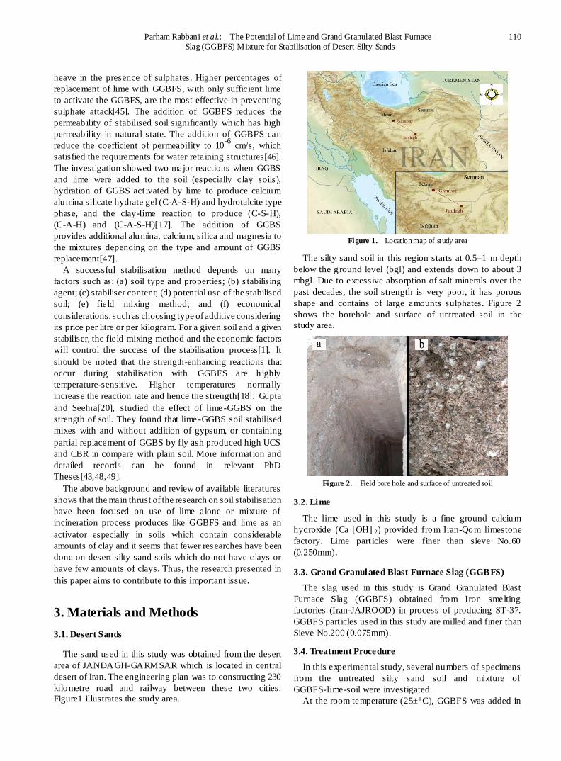
The sand used in this study was obtained from the desert
area of JANDAGH-GARMSAR which is located in central
desert of Iran. The engineering plan was to constructing 230
kilometre road and railway between these two cities.
Figure1 illustrates the study area.
Figure 1. Location map of study area
The silty sand soil in this region starts at 0.5–1 m depth
below the g round level (bgl) and extends down to about 3
mbgl. Due to excessive absorption of salt minerals over the
past decades, the soil strength is very poor, it has porous
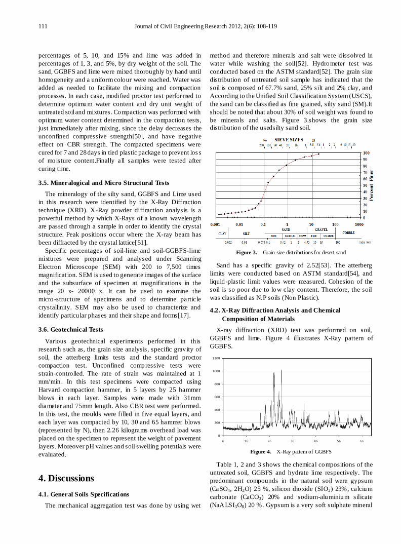
shape and contains of large amounts sulphates. Figure 2
shows the borehole and surface of untreated soil in the
study area.
Figure 2. Field bore hole and surface of untreated soil
3.2. Lime
The lime used in this study is a fine ground calcium
hydroxide (Ca [OH] 2) provided from Iran-Qom limestone
factory. Lime part icles were finer than sieve No.60
(0.250mm).
3.3. Grand Granulated Blast Furnace Slag (GGBFS)
The slag used in this study is Grand Granulated Blast
Furnace Slag (GGBFS) obtained from Iron smelting
factories (Iran-JAJROOD) in process of producing ST-37.
GGBFS part icles used in this study are milled and finer than
Sieve No.200 (0.075mm).
3.4. Treatment Procedure
In this experimental study, several numbers of specimens
from the untreated silty sand soil and mixture of
GGBFS-lime-soil were investigated.
At the room temperature (25±°C), GGBFS was added in
111 Journal of Civil Engineering Research 2012, 2(6): 108-119
percentages of 5, 10, and 15% and lime was added in
percentages of 1, 3, and 5%, by dry weight of the soil. The
sand, GGBFS and lime were mixed thoroughly by hand until
homogeneity and a uniform colour were reached. Water was
added as needed to facilitate the mixing and compaction
processes. In each case, modified proctor test performed to
determine optimum water content and dry unit weight of
untreated soil and mixtures. Compaction was performed with
optimum water content determined in the compaction tests,
just immediately after mixing, since the delay decreases the
unconfined compressive strength[50], and have negative
effect on CBR strength. The compacted specimens were
cured for 7 and 28 days in tied plastic package to prevent los s
of moisture content.Finally all samples were tested after
curing time.
3.5. Mineralogical and Micro Structural Tests
The mineralogy of the silty sand, GGBFS and Lime used
in this research were identified by the X-Ray Diffraction
technique (XRD). X-Ray powder diffraction analysis is a
powerful method by which X-Rays of a known wavelength
are passed through a sample in order to identify the crystal
structure. Peak positions occur where the X-ray beam has
been diffracted by the crystal lattice[51].
Specific percentages of soil-lime and soil-GGBFS-lime
mixtures were prepared and analysed under Scanning
Electron Microscope (SEM) with 200 to 7,500 times
magnificat ion. SEM is used to generate images of the surface
and the subsurface of specimen at magnifications in the
range 20 x- 20000 x. It can be used to examine the
micro -structure of specimens and to determine particle
crystallinity. SEM may also be used to characterize and
identify particu lar phases and their shape and forms[17].
3.6. Geotechnical Tests
Various geotechnical experiments performed in this
research such as, the grain size analysis, specific grav ity of
soil, the atterberg limits tests and the standard proctor
compaction test. Unconfined compressive tests were
strain-controlled. The rate of strain was maintained at 1
mm/min . In this test specimens were compacted using
Harvard compaction hammer, in 5 layers by 25 hammer
blows in each layer. Samples were made with 31mm
diameter and 75mm length. Also CBR test were performed.
In this test, the moulds were filled in five equal layers, and
each layer was compacted by 10, 30 and 65 hammer blows
(represented by N), then 2.26 kilograms overhead load was
placed on the specimen to represent the weight of pavement
layers. Moreover pH values and soil swelling potentials were
evaluated.
4. Discussions
4.1. General Soils Specifications
The mechanical aggregation test was done by using wet
method and therefore minerals and salt were d issolved in
water while washing the soil[52]. Hydrometer test was
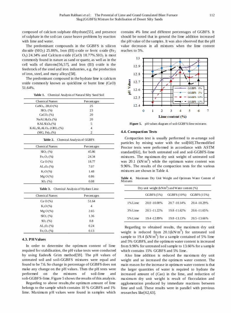
conducted based on the ASTM standard[52]. The grain size
distribution of untreated soil sample has indicated that the
soil is composed of 67.7% sand, 25% silt and 2% clay, and
According to the Unified Soil Classification System (USCS),
the sand can be classified as fine grained, silty sand (SM).It
should be noted that about 30% of soil weight was found to
be minerals and salts. Figure 3.shows the grain size
distribution of the usedsilty sand soil.
Figure 3. Grain size distributions for desert sand
Sand has a specific gravity of 2.52[53]. The atterberg
limits were conducted based on ASTM standard[54], and
liquid -plastic limit values were measured. Cohesion of the
soil is so poor due to low clay content. Therefore, the soil
was classified as N.P soils (Non Plastic).
4.2. X-Ray Diffraction Analysis and Chemical
Composition of Materials
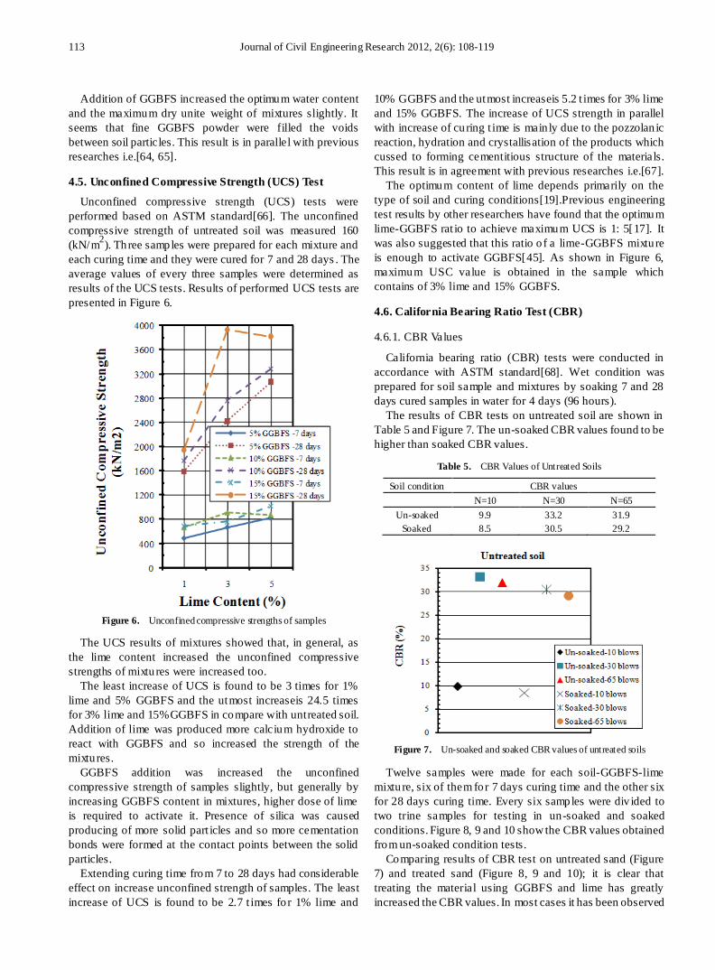
X-ray diffraction (XRD) test was performed on soil,
GGBFS and lime. Figure 4 illustrates X-Ray pattern of
GGBFS.
Figure 4. X-Ray pattern of GGBFS
Table 1, 2 and 3 shows the chemical compositions of the
untreated soil, GGBFS and hydrate lime respectively. The
predominant compounds in the natural soil were gypsum
(CaSO4, 2H2O) 25 %, silicon dioxide (SIO2) 23%, calcium
carbonate (CaCO3) 20% and sodium-aluminium silicate
(NaALSI3O8) 20 %. Gypsum is a very soft sulphate mineral
Parham Rabbani et al.: The Potential of Lime and Grand Granulated Blast Furnace 112
Slag (GGBFS) Mixture for Stabilisation of Desert Silty Sands
composed of calcium sulphate dihydrate[55], and presence
of sulphate in the soil can cause heave problems by reaction
with lime and water.
The predominant compounds in the GGBFS is silicon
dioxide (SIO2) 25.86%, Iron (III) oxide or ferric oxide (Fe2
O3) 24.34% and Calcium oxide (CaO) 18.77%.SIO2 is most
commonly found in nature as sand or quartz, as well as in the
cell walls of diatoms[56,57], and Iron (III) oxide is the
feedstock of the steel and iron industries, e.g. the production
of iron, steel, and many alloys[58].
The predominant compound in the hydrate lime is calcium
oxide commonly known as quicklime or burnt lime (CaO)
51.64%.
Table 1. Chemical Analysis of Natural Silty Sand Soil
Chemical Names Percentages
CaSO4, 2H2O (%) 25
SIO2 (%) 23
CaCO3 (%) 20
NaALSI3O8 (%) 20
KALSI3O8 (%) 5
KAL2SI3ALO10 (OH) 2 (%) 4
(MG, Fe) 6 (%) 2
Table 2. Chemical Analysis of GGBFS
Chemical Names Percentages
SIO2 (%) 45.86
Fe2 O3 (%) 24.34
Ca O (%) 18.77
AL2O3 (%) 7.07
K2O (%) 1.48
Mg O (%) 0.86
SO3 (%) 0.08
Table 3. Chemical Analysis of Hydrate Lime
Chemical Names Percentages
Ca O (%) 51.64
K2O (%) 4
Mg O (%) 2.65
SIO2 (%) 1.36
SO3 (%) 0.8
AL2O3 (%) 0.24
Fe2 O3 (%) 0.13
4.3. PH Values
In order to determine the optimum content of lime
required fo r stabilisation, the pH value tests were conducted
by using Eades& Grim method[59]. The pH values of
untreated soil and soil-GGBFS mixtures were equal and
found to be 7.6. So change in percentage of GGBFS does not
make any change on the pH values. Then the pH tests were
performed on the mixtures of soil-lime and
soli-GGBFS-lime. Figure 5 shows the results of this analysis.
Regarding to above results,the optimum amount of lime
belongs to the sample which contains 10 % GGBFS and 1%
lime. Maximum pH values were found in samples which
contains 4% lime and different percentages of GGBFS. It
should be noted that in general the lime addition increased
the pH value of the samples. It was also observed that the pH
value decreases in all mixtures when the lime content
reaches to 5%.
Figure 5. pH values diagram of soil-GGBFS-lime mixtures
4.4. Compaction Tests
Compaction test is usually performed to re-arrange soil
particles by mixing water with the soil[60].Themodified
Proctor tests were performed in accordance with ASTM
standard[61], for both untreated soil and soil-GGBFS-lime
mixtures. The maximum dry unit weight of untreated soil
was 20.1 (kN/m3) while the optimum water content was
9.96%. The results of the compaction tests for the various
mixtures are shown in Table 4.
Table 4. Maximum Dry Unit Weight and Optimum Water Content of Mixtures
Dry unit weight (kN/m3) and Water content (%)
GGBFS (5%) GGBFS (10%) GGBFS (15%)
1% Lime 20.0 -10.00% 20.7 -10.14% 20.4 -10.29%
3% Lime 20.5 -11.22% 19.8 -11.62% 20.6 -11.65%
5% Lime 19.4 -12.89% 19.8 -13.13% 20.5 -13.66%
Regarding to obtained results, the maximum dry unit
weight is reduced from 20.1(kN/m3) for untreated soil
sample to 19.4 (kN/m3) for a sample contained of 5% lime
and 5% GGBFS, and the optimum water content is increased
from 9.96% for untreated soil sample to 13.66% for a sample
which contains 15% GGBFS and 5% lime.
Also lime addition is reduced the maximum dry unit
weight and so increased the optimum water content. The
main reason for the increase in optimum water content is that
the larger quantities of water is required to hydrate the
increased amount of (Cao) in the lime, and reduction of
maximum dry unit weight is result of flocculation and
agglomerat ion produced by immediate reactions between
lime and soil. These results were in parallel with previous
researches like[62,63].
113 Journal of Civil Engineering Research 2012, 2(6): 108-119
Addition of GGBFS increased the optimum water content
and the maximum dry unite weight of mixtures slightly. It
seems that fine GGBFS powder were filled the voids
between soil particles. This result is in parallel with previous
researches i.e.[64, 65].
4.5. Unconfined Compressive Strength (UCS) Test
Unconfined compressive strength (UCS) tests were
performed based on ASTM standard[66]. The unconfined
compressive strength of untreated soil was measured 160
(kN/m2). Three samples were prepared for each mixture and
each curing time and they were cured for 7 and 28 days . The
average values of every three samples were determined as
results of the UCS tests. Results of performed UCS tests are
presented in Figure 6.
Figure 6. Unconfined compressive strengths of samples
The UCS results of mixtures showed that, in general, as
the lime content increased the unconfined compressive
strengths of mixtures were increased too.
The least increase of UCS is found to be 3 times for 1%
lime and 5% GGBFS and the utmost increaseis 24.5 times
for 3% lime and 15%GGBFS in compare with untreated soil.
Addition of lime was produced more calcium hydroxide to
react with GGBFS and so increased the strength of the
mixtures.
GGBFS addition was increased the unconfined
compressive strength of samples slightly, but generally by
increasing GGBFS content in mixtures, higher dose of lime
is required to activate it. Presence of silica was caused
producing of more solid part icles and so more cementation
bonds were formed at the contact points between the solid
particles.
Extending curing time from 7 to 28 days had considerable
effect on increase unconfined strength of samples. The least
increase of UCS is found to be 2.7 t imes fo r 1% lime and
10% GGBFS and the utmost increaseis 5.2 t imes for 3% lime
and 15% GGBFS. The increase of UCS strength in parallel
with increase of curing t ime is main ly due to the pozzolan ic
reaction, hydration and crystallisation of the products which
cussed to forming cementitious structure of the materials.
This result is in agreement with previous researches i.e.[67].
The optimum content of lime depends primarily on the
type of soil and curing conditions[19].Previous engineering
test results by other researchers have found that the optimum
lime-GGBFS rat io to achieve maximum UCS is 1: 5[17]. It
was also suggested that this ratio o f a lime-GGBFS mixture
is enough to activate GGBFS[45]. As shown in Figure 6,
maximum USC value is obtained in the sample which
contains of 3% lime and 15% GGBFS.
4.6. California Bearing Ratio Test (CBR)
4.6.1. CBR Values
California bearing ratio (CBR) tests were conducted in
accordance with ASTM standard[68]. Wet condition was
prepared for soil sample and mixtures by soaking 7 and 28
days cured samples in water for 4 days (96 hours).
The results of CBR tests on untreated soil are shown in
Table 5 and Figure 7. The un-soaked CBR values found to be
higher than soaked CBR values.
Table 5. CBR Values of Untreated Soils
Soil condition CBR values
N=10 N=30 N=65
Un-soaked 9.9 33.2 31.9
Soaked 8.5 30.5 29.2
Figure 7. Un-soaked and soaked CBR values of untreated soils
Twelve samples were made for each soil-GGBFS-lime
mixture, six of them for 7 days curing time and the other six
for 28 days curing time. Every six samples were div ided to
two trine samples for testing in un-soaked and soaked
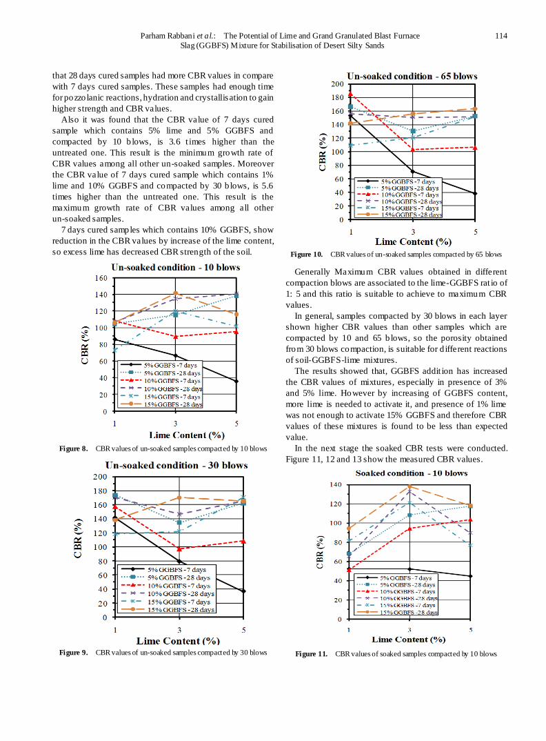
conditions. Figure 8, 9 and 10 show the CBR values obtained
from un-soaked condition tests.
Comparing results of CBR test on untreated sand (Figure
7) and treated sand (Figure 8, 9 and 10); it is clear that
treating the material using GGBFS and lime has greatly
increased the CBR values. In most cases it has been observed
Parham Rabbani et al.: The Potential of Lime and Grand Granulated Blast Furnace 114
Slag (GGBFS) Mixture for Stabilisation of Desert Silty Sands
that 28 days cured samples had more CBR values in compare
with 7 days cured samples. These samples had enough time
for pozzo lanic reactions, hydration and crystallisation to gain
higher strength and CBR values.
Also it was found that the CBR value of 7 days cured
sample which contains 5% lime and 5% GGBFS and
compacted by 10 b lows, is 3.6 t imes higher than the
untreated one. This result is the minimum growth rate of
CBR values among all other un-soaked samples. Moreover
the CBR value of 7 days cured sample which contains 1%
lime and 10% GGBFS and compacted by 30 b lows, is 5.6
times higher than the untreated one. This result is the
maximum growth rate of CBR values among all other
un-soaked samples.
7 days cured samples which contains 10% GGBFS, show
reduction in the CBR values by increase of the lime content,
so excess lime has decreased CBR strength of the soil.
Figure 8. CBR values of un-soaked samples compacted by 10 blows
Figure 9. CBR values of un-soaked samples compacted by 30 blows
Figure 10. CBR values of un-soaked samples compacted by 65 blows
Generally Maximum CBR values obtained in different
compaction blows are associated to the lime-GGBFS rat io of
1: 5 and this ratio is suitable to achieve to maximum CBR
values.
In general, samples compacted by 30 blows in each layer
shown higher CBR values than other samples which are
compacted by 10 and 65 b lows, so the porosity obtained
from 30 blows compaction, is suitable for d ifferent reactions
of soil-GGBFS-lime mixtures.
The results showed that, GGBFS addit ion has increased
the CBR values of mixtures, especially in presence of 3%
and 5% lime. However by increasing of GGBFS content,
more lime is needed to activate it, and presence of 1% lime
was not enough to activate 15% GGBFS and therefore CBR
values of these mixtures is found to be less than expected
value.
In the next stage the soaked CBR tests were conducted.
Figure 11, 12 and 13 show the measured CBR values.
Figure 11. CBR values of soaked samples compacted by 10 blows
115 Journal of Civil Engineering Research 2012, 2(6): 108-119
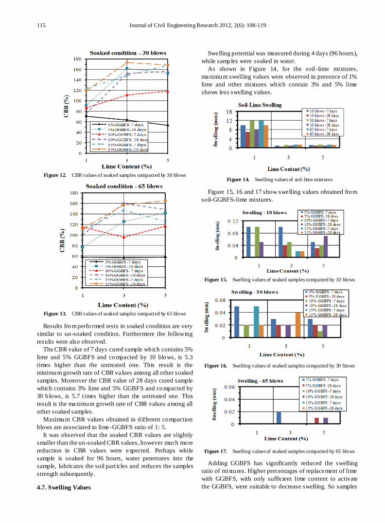
Figure 12. CBR values of soaked samples compacted by 30 blows
Figure 13. CBR values of soaked samples compacted by 65 blows
Results from performed tests in soaked condition are very
similar to un-soaked condition. Furthermore the following
results were also observed.
The CBR value of 7 days cured sample which contains 5%
lime and 5% GGBFS and compacted by 10 blows, is 5.3
times higher than the untreated one. This result is the
minimum growth rate of CBR values among all other soaked
samples. Moreover the CBR value of 28 days cured sample
which contains 3% lime and 5% GGBFS and compacted by
30 b lows, is 5.7 t imes higher than the untreated one. This
result is the maximum growth rate of CBR values among all
other soaked samples.
Maximum CBR values obtained in d ifferent compaction
blows are associated to lime-GGBFS ratio of 1: 5.
It was observed that the soaked CBR values are slightly
smaller than the un-soaked CBR values, however much more
reduction in CBR values were expected. Perhaps while
sample is soaked for 96 hours, water penetrates into the
sample, lubricates the soil part icles and reduces the samples
strength subsequently.
4.7. Swelling Values
Swelling potential was measured during 4 days (96 hours),
while samples were soaked in water.
As shown in Figure 14, for the soil-lime mixtures,
maximum swelling values were observed in presence of 1%
lime and other mixtures which contain 3% and 5% lime
shows less swelling values.
Figure 14. Swelling values of soil-lime mixtures
Figure 15, 16 and 17 show swelling values obtained from
soil-GGBFS-lime mixtures.
Figure 15. Swelling values of soaked samples compacted by 10 blows
Figure 16. Swelling values of soaked samples compacted by 30 blows
Figure 17. Swelling values of soaked samples compacted by 65 blows
Adding GGBFS has significantly reduced the swelling
ratio of mixtures. Higher percentages of replacement of lime
with GGBFS, with only sufficient lime content to activate
the GGBFS, were suitable to decrease swelling. So samples
Parham Rabbani et al.: The Potential of Lime and Grand Granulated Blast Furnace 116
Slag (GGBFS) Mixture for Stabilisation of Desert Silty Sands
which contain 15% GGBFS generally show the minimum
swelling values.
In general, it was found that samples compacted by 65
blows in each layer show the min imum swelling values than
other samples which have been compacted by 10 and 30
blows, so there is a d irect relat ionship between minimum
porosity obtained from compaction and decrease of swelling
values.
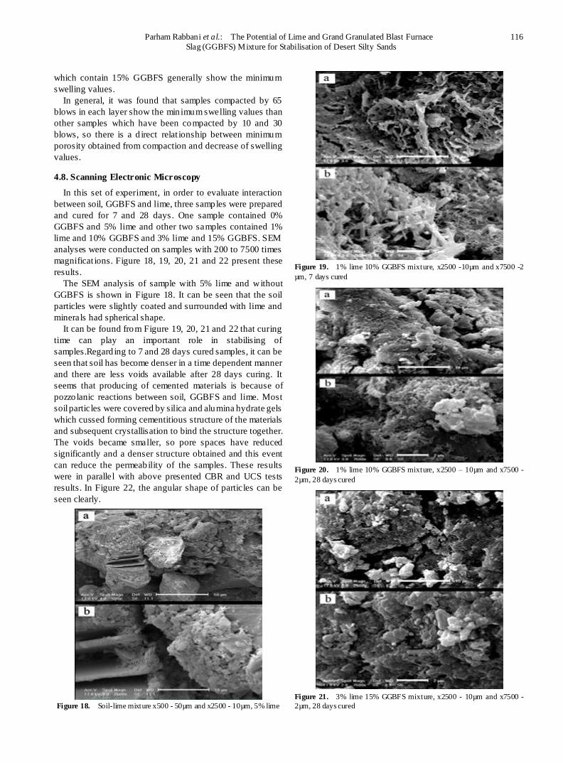
4.8. Scanning Electronic Microscopy
In this set of experiment, in order to evaluate interaction
between soil, GGBFS and lime, three samples were prepared
and cured for 7 and 28 days . One sample contained 0%
GGBFS and 5% lime and other two samples contained 1%
lime and 10% GGBFS and 3% lime and 15% GGBFS. SEM
analyses were conducted on samples with 200 to 7500 times
magnificat ions. Figure 18, 19, 20, 21 and 22 present these
results.
The SEM analysis of sample with 5% lime and without
GGBFS is shown in Figure 18. It can be seen that the soil
particles were slightly coated and surrounded with lime and
minerals had spherical shape.
It can be found from Figure 19, 20, 21 and 22 that curing
time can play an important role in stabilising of
samples.Regard ing to 7 and 28 days cured samples, it can be
seen that soil has become denser in a time dependent manner
and there are less voids available after 28 days curing. It
seems that producing of cemented materials is because of
pozzo lanic reactions between soil, GGBFS and lime. Most
soil particles were covered by silica and alumina hydrate gels
which cussed forming cementitious structure of the materials
and subsequent crystallisation to bind the structure together.
The voids became smaller, so pore spaces have reduced
significantly and a denser structure obtained and this event
can reduce the permeability of the samples. These results
were in parallel with above presented CBR and UCS tests
results. In Figure 22, the angular shape of particles can be
seen clearly.
Figure 18. Soil-lime mixture x500 - 50µm and x2500 - 10µm, 5% lime
Figure 19. 1% lime 10% GGBFS mixture, x2500 -10µm and x7500 -2
µm, 7 days cured
Figure 20. 1% lime 10% GGBFS mixture, x2500 – 10µm and x7500 -
2µm, 28 days cured
Figure 21. 3% lime 15% GGBFS mixture, x2500 - 10µm and x7500 -
2µm, 28 days cured
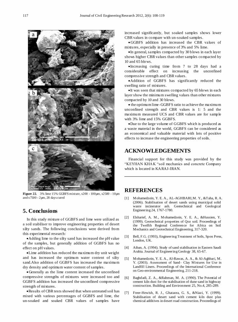
117 Journal of Civil Engineering Research 2012, 2(6): 108-119
Figure 22. 3% lime 15% GGBFS mixture, x200 - 100µm, x2500 - 10µm
and x7500 - 2µm, 28 days cured
5. Conclusions
In this study mixture o f GGBFS and lime were utilized as
a soil stabiliser to improve engineering properties of desert
silty sands. The following conclusions were derived from
this experimental research:
Adding lime to the silty sand has increased the pH value
of the samples, but generally addition of GGBFS has no
effect on pH values.
Lime addition has reduced the maximum dry unit weight
and has increased the optimum water content of silty
sand.Also addition of GGBFS has increased the maximum
dry density and optimum water content of samples.
Generally as the lime content increased the unconfined
compressive strengths of mixtures were increased too and
GGBFS addition has increased the unconfined compressive
strength of mixtures.
Results of CBR tests showed that when untreated soil has
mixed with various percentages of GGBFS and lime, the
un-soaked and soaked CBR values of samples have
increased significantly, but soaked samples shows lower
CBR values in compare with un-soaked samples.
GGBFS addition has increased the CBR values of
mixtures, especially in presence of 3% and 5% lime.
In general, samples compacted by 30 b lows in each layer
shows higher CBR values than other samples compacted by
10 and 65 blows.
Increasing curing time from 7 to 28 days had a
considerable effect on increasing the unconfined
compressive strength and CBR values.
Addition of GGBFS has significantly reduced the
swelling ratio of mixtures.
It was seen that mixtures compacted by 65 blows in each
layer show the minimum swelling values than other mixtures
compacted by 10 and 30 blows.
the optimum lime-GGBFS ratio to achieve the maximum
unconfined strength and CBR values is 1: 5 and the
maximum measured UCS and CBR values are for sample
with 3% lime and 15% GGBFS.
Due to the large volume of GGBFS which is produced as
a waste material in the world, GGBFS can be considered as
an economical and valuable material with lots of positive
effects to increase the engineering properties of soils.
ACKNOWLEDGEMENTS
Financial support for this study was provided by the
“KEYHAN KHAK “soil mechanics and concrete Company
which is located in KARAJ-IRAN.
REFERENCES
[1] Mohamedzein, Y. E. A., AL-AGHBARI, M. Y., &Taha, R. A.
(2006). Stabilisation of desert sands using municipal solid waste incinerator ash. Geotechnical and Geological Engineering 24, 1767-1780.
[2] Elsharief, A. M., Mohamedzein, Y. E. A., &Hussien, Y.
(1999). Geotechnical properties of Qoz soil. Proceedings of the Twelfth Regional Conference for Africa on Soil Mechanics and Geotechnical Engineering, 317-320.
[3] Bell, F.G. (1993), Engineering Treatment of Soils, Spon Press, London, UK.
[4] Aiban, A. (1994). Study of sand stabilisation in Eastern Saudi Arabia. Journal of Engineering Geology 38, 65-67.
[5] Mohamedzein, Y. E. A., Al-Rawas, A. A., & Al-Aghbari, M. Y. (2003). Assessment of Sand– Clay Mixtures for Use in
Landfill Liners. Proceedings of the International Conference on Geo-environmental Engineering, 211-218.
[6] Baghdadi, Z. A., &Rahman, M. A. (1990). The Potential of cement kiln dust for the stabilisation of dune sand in highway construction. Building and Environment 25, No.4, 285-289.
[7] Freer-Hewish, R. J., Ghataora, G. S., &Niazi, Y. (1999).
Stabilisation of desert sand with cement kiln dust plus chemical additives in desert road construction. Proceedings of

Parham Rabbani et al.: The Potential of Lime and Grand Granulated Blast Furnace 118
Slag (GGBFS) Mixture for Stabilisation of Desert Silty Sands
the Institution of Civil Engineer, Transport, 135, No. 1, 29-36.
[8] O’Sadnick, D. L., Simpson, B. E., &Kasel, G. K. (1995).
Evaluation and performance of a Sand/Bentonite Liner. Proceedings of a Specialty Geoenvironment 2000, ASCE, New Orleans, Louisiana, USA, 688-701.
[9] Taha, R. A., &Pradeep, M. R. Use of fly Ash–Stabilised Sand Mixtures as Capping Materials for Landfills. Proceedings of
the Symposium on Testing Soil with waste or Recycled Materials, ASTM. New Orleans, Louisiana, USA, 1997, pp.172-180
[10] Turner, J. P. (1997). Evaluation of Western coal fly ashes for stabilisation of low-volume roads. Proceedings of the 1997
Symposium on Testing Soil with waste or Recycled Materials, ASTM, New Orleans, Louisiana, USA, 157-171.
[11] Consoli, N. C., Montardo, J. P., Prietto, P. D. M., &Pasa, G. S. (2002). Engineering behavior of a sand reinforced with plastic waste. Journal of Geotechnical and Geoenvironmental
Engineering, ASCE 128, No. 6, 462-472.
[12] Wahab, H. I. A. &Asi, I. M. (1997). Improvement of marl and dune sand for highway construction in arid areas. Journal of Building and Environment 32, No. 3, 271-279.
[13] Ingles, O. G., & Metcalf, J. B. Soil Stabilisation: Principles and Practice. Sydney, Butterworths, 1972, pp. 127-167.
[14] Al-Khanbashi, A., Mohamed, A. M. O., Moet, A., &Hadi, B. Stabilisation of desert sand using water-borne polymers. First
International Conference on Geotechnical, Geoenvironmental Engineering and Management in arid Lands, United Arab Emirates, 2000, pp.143-148.
[15] Kaniraj, S. R., &Havanagi, V. G. (2001). Behavior of cement-stabilised fiber-reinforced fly ash-soil mixtures.
Journal of Geotechnical and Geoenvironmental Engineering, ASCE 127, No. 7, 574-584.
[16] Bhuyan, S., & Singh, S. P. (2010). Stabilisation of balast furnace slag and fly ash using lime and Rbi grade 81. BS Thesis, Department of Civil Engineering, National Institute of
Technology Rourkela, India.
[17] Abdel RahmanOuf, M. E. S. (2001). Stabilisation of clay subgrade soil using ground granulated ballast furnace slag. PhD Thesis, University of Leeds, U.K.
[18] Axelsson, K., Johansson, S. E., &Andersson, R. (2000). Stabilisation of Organic Soils by Cement and Pozzolanic
Reactions. Feasibility study, Swedish Geotechnical Institute,Swedish Deep Stabilisation Research Centre.
[19] Higgins, D. D., Kinuthia, J. M., & Wild, S. (1998). Soil Stabilisation Using Lime-Activated GGBS. Proceedings of the 6th. Conference, Fly Ash, Silica fume, Slag, and Natural
Pozzolans in Concrete 2, 1057-1074.
[20] Gupta, S., &Seehra, S. S. (1989). Studies on Lime Granulated
Blast Furnace Slag as an Alternative Binder to Cement. Highways Research Board, Bulletin, No. 38, 81-97.
[21] Gjorv, O. E. (1989). Alkali Activation of Norwegian
Granulated Blast Furnace Slag. Proceedings of the Third International Conference Trondheim 2, 1501-1517.
[22] Sherwood, P. T. Soil stabilisation with Cement and Lime- state of the art review: HMSO Publication, London, 1993.
[23] Serruto, M., &Pardo, L. (2001). Evaluation of Stabilised
Marginal Pavement Materials Using Established and Newly Developed Cementitious Binders. 20th ARRB Conference Melbourne.
[24] Meggs, R. Stabilisation- Cementitious blends incorporating GGBFS (Technical Note 15): VicRoads Materials
Technology Department, Victoria, Australia. 1996.
[25] McDowell, C. (1966). Evaluation of Soil-Lime Stabilisation
Mixtures. Highway Research Record, No.139, 15-24.
[26] Bell, F. G. (1996). Lime Stabilisation of Clay Minerals and
Soils. Engineering Geology 42, 223-237.
[27] Kavak, A., Keskin, E., &Akyarh, A. (2007). A field
application for lime stabilisation. Environ Geol 51, 987-997.
[28] Mallela, J., Quintus, H. V., & Smith, K. L. (2004). Consideration of Lime-Stabilised Layers in Mechanistic-Empirical Pavement Design. The National Lime
Association.
[29] Rogers, C. D. F., Glendinning, S., &Roff, T. E. J. (1997).
Lime Modification of Clay Soils for Construction Expediency. Proceedings of the Institution of Civil Engineers, Geotechnical Engineering 125, 242-249.
[30] Bell, F. G., &Coulthard, J. M. (1990). Stabilisation of Clay Soils with Lime. Proceedings of the Institution of Civil
Engineers, Municipal Engineer, No.7, 125-140.
[31] Bari, F. (1995). Stabilisation of Clay Soils with Lime. MSc
Thesis, University of Leeds, U.K.
[32] Thompson, M. R. (1966). Lime Reactivity of Illinois Soils.
Journal of Soil Mechanics and Foundations Division, ASCE 92, 67-91.
[33] Kavak, A. (1996). The behavior of lime stabilised clays under cyclic loading. Ph.D. dissertation, Bogazici University.
Istanbul.
[34] Kavak, A., & Baykal, G. I. (2001). behavior of lime-stabilised
clays subjected to repeated loading. Proceedings of the 15th international conference on soil mechanics and geotechnical engineering, Istanbul.
[35] Thompson, M. R. (1969). Engineering properties of lime-soil mixtures. Journal of materials, JMLSA, 4, No. 4, 968-969.
[36] Newbauer, C. H., & Thompson, M. R. (1972). Stability properties of uncured limetreated fine grained soils. Highway
Research Recor, No. 381, National Research Council, Washington DC, 20-26.
[37] Rao, S., &Shivananda, P. (2005). Impact of Sulphate Contamination on Swelling Behavior of Lime-Stabilised Clays. Geotechnical Testing Journal, ASTM 2,No.4, 1-10.
[38] Wang, L. (2002). Cementitouse Stabilisation of Soils in the
Presence of Sulphate. PhD Theses, Louisiana State University. U.S.A.
[39] Mitchell, J. K. (1986). Delayed Failure of Lime-Stabilised Pavement Bases. Journal of Geotechnical AndGeoenvironmental Engineering, ASCE 112, 274-279.
[40] Hunter, D. (1988). Lime-induced heave in sulphate-bearing clay soils. Journal of Geotechnical AndGeoenvironmental
Engineering, ASCE 114, 150-167.
[41] Snedker, E. A. & Temporal, J. (1990). M40 motorway
119 Journal of Civil Engineering Research 2012, 2(6): 108-119
Banbury IV contract - Lime Stabilisation. Institution of Highways & Transportation, London, U.K. 37,No.12, 7-8.
[42] Wild, S., Kinuthia, J. M., Jones, G. I., & Higgins, D. D. (1999). Suppression of swelling associated with ettringite formation in lime-stabilised sulphate-bearing clay soils by
partial substitution of lime with ground granulated blast furnace slag. Engineering Geology 51, 257-277.
[43] Veith, G. H. (2000). Engineering Properties of Sulphate-Bearing Clay Soils Stabilised with Lime Activated GGBS. PhD thesis, Glamorgan, U.K.
[44] Higgins, D. D. (2005). Soil Stabilisation with Ground Granulated Blast furnace Slag. UK Cementitious Slag Makers
Association (CSMA).
[45] Wild, S., &Tasong, W. A. (1999). Influence of Ground
Granulated Blast furnace Slag on the Sulphate Resistance of Lime- Stabilised Kaolinite. Magazine of Concrete Research 51, No. 4, 247-254.
[46] Yamanouchi, Y., Monna, I., & Hirose, T. (1982).
Seepage-Cut- Soil Stabilisation with Newly Developed Slag-Cement. Symposium on Recent Development in Ground Improvement Techniques, Bangkok, 507-511.
[47] Regourd, M. (1980). Structure and Behavior of Slag Portland Cement Hydrates. 7th International Congress on the
Chemistry of Cement, Paris, France, Sub-Theme 111-2, 2, 10-26.
[48] Kinuthia, J. M. (1997). Property changes and mechanisms in lime stabilised Kaolinite in the presence of metal sulphates. PhD Thesis, University of Glamorgan. U.K
[49] Thomas, B. (1999). Strength Development Durability and Linear Expansion of Sulphide Rich Clay Soils Stabilised
With Lime Activated GGBS. PhD Thesis, University of Glamorgan, U.K.
[50] Bin-Shafique, S., Edil, T. B., Benson, C. H., &Senal, A. (2004). Incorporating a fly-ash stabilised layer into pavement design. Proceedings of the Institution of Civil Engineers -
Geotechnical Engineering 157, No.4, 239-249.
[51] Warren, B. E. X-ray Diffraction, Dover Publications, New York, 1990.
[52] ASTM (American Society for Testing and Materials) (2002). Standard Test Method for Particle-Size Analysis of Soils,D422–63. West Conshohocken, PA: ASTM.
[53] ASTM (American Society for Testing and Materials) (2002). Standard Test Methods for Specific Gravity of Soil Solids by
Water Pycnometer, D854–02. West Conshohocken, PA: ASTM.
[54] ASTM (American Society for Testing and Materials) (2002). Standard Test Methods for Liquid Limit, Plastic Limit, and Plasticity Index of Soils, D4318-00, West Conshohocken, PA:
ASTM.
[55] Klein, C., &Hurlbut, C. S., Manual of Mineralogy, 20th edn, John Wiley, New York, 1985, pp. 352–353, ISBN 0-471-80580-7.
[56] Iler, R. K. The Chemistry of Silica. Wiley-Interscience: New. York, 1979.ISBN047102404X.
[57] Lynn Townsend White, J. R. (1961). A Case Study of Technological Innovation, Its Context and Tradition.
Technology and Culture(Society for the History of Technology) 2, No.2, 97-111.
[58] Greenwood, N. N., &Earnshaw, A. Chemistry of the Element, 2nd edn.Butterworth Heinemann, Oxford, London, 1997.ISBN0-7506-3365-4.
[59] Eades, J. E., & Grim, R. E. (1963). a Quick Test to Determine Lime Requirements for Lime Stabilisation. Highway
Research Board, Record No. 139, pp 61–72.
[60] Chen, L., & Lin, D. F. (2009). Stabilisation treatment of soft subgrade soil by sewage sludge ash and cement. Journal of Hazardous Materials 162, 321-327.
[61] ASTM (American Society for Testing and Materials) (2002).Standard Test Methods for Laboratory Compaction
Characteristics of Soil Using, D1557-02. West Conshohocken, PA: ASTM.
[62] Little, D. N. Handbook for Stabilisation of Pavement Sub- Grade and Base Courses with Lime. National Lime Association: Kendall Hunt Publishing Company.Lowa, USA,
1995.
[63] Rogers, C. D. F. (1988). Lime Stabilisation. Ground
Engineering, 7-10.
[64] Akinmusuru, J. O. (1991). Potential Beneficial Uses of Steel
Slag Wastes for Civil Engineering Purposes. Resources Conservation and Recycling 5, 73-80.
[65] Wild, S., Kinuthia, J. M., Robinson, R. B., & Humphreys. (1996). Effects of Ground Granulated Blast Furnace Slag
(GGBS) on the Strength and Swelling Properties of Lime - Stabilised Kaolinite in The Presence of Sulphates. Clay Mineralogy, No. 31, 423-433.
[66] ASTM (American Society for Testing and Materials) (2002). Standard Test Method for Unconfined Compressive Strength
of Cohesive Soil, D2166–00. West Conshohocken, PA: ASTM.
[67] Cabrera, J. G., &Nwakanma, C. A. (1979). Pozzolanic Activity and Mechanism of Reaction of Red Tropical Soil-Lime System. Transportation Research Record, National
Research Council, Washington D.C. No.702, 199-207
[68] ASTM (American Society for Testing and Materials) (2002).
Standard Test Method for CBR (California Bearing Ratio) of Laboratory-Compacted Soils, D1883–99. West Conshohocken, PA: ASTM.