THE PLC CONTROL OF AN ELECTRICAL SYSTEM … · input from PLC Signal Board Analog Output. For...
8
JET 11 JET Volume 11 (2018) p.p. 11-18 Issue 4, December 2018 Type of arcle 1.01 www.fe.um.si/en/jet.html THE PLC CONTROL OF AN ELECTRICAL SYSTEM CONSISTING OF AN ELECTROMAGNETICALLY SLIDING BRAKE AND COUPLING UPORABA PLC KRMILNIKA PRI VODENJU ELEKTRIČNEGA SISTEMA SESTAVLJENEGA IZ ELEKTROMAGNETNE DRSNE ZAVORE IN SKLOPKE Georgel Gabor R , Adrian Traian Plesca 1 Keywords: Electromagnecally sliding couple, electromagnecally sliding brake, PLC, PROFIBUS, Variable Frequency Converter, Industrial communicaon Abstract This paper describes an electrical system consisng of electrical sliding coupling driven by a 3 phase electric motor and electric sliding brake. A frequency converter provides control of the motor. Fur- thermore, the communicaon between PLC and frequency converter is done using PROFIBUS com- municaon. The data are displayed on a SIEMENS HMI display. The goal is to control the electrical sliding coupling, which is mechanically connected to the electrical sliding brake. R Corresponding author: Mr Georgel Gabor, Technical University “Gheorghe Asachi” of Iasi, Department of Electri- cal Engineering, Tel: +4074232343, E-mail address: [email protected] 1 Technical University “Gheorghe Asachi” of Iasi, Department of Power Engineering, Romania
Transcript of THE PLC CONTROL OF AN ELECTRICAL SYSTEM … · input from PLC Signal Board Analog Output. For...

JET 11
JET Volume 11 (2018) p.p. 11-18Issue 4, December 2018
Type of article 1.01www.fe.um.si/en/jet.html
THE PLC CONTROL OF AN ELECTRICAL SYSTEM CONSISTING OF AN
ELECTROMAGNETICALLY SLIDING BRAKE AND COUPLING
UPORABA PLC KRMILNIKA PRI VODENJU ELEKTRIČNEGA SISTEMA
SESTAVLJENEGA IZ ELEKTROMAGNETNE DRSNE ZAVORE IN SKLOPKE
Georgel GaborR, Adrian Traian Plesca1
Keywords: Electromagnetically sliding couple, electromagnetically sliding brake, PLC, PROFIBUS, Variable Frequency Converter, Industrial communication
AbstractThis paper describes an electrical system consisting of electrical sliding coupling driven by a 3 phase electric motor and electric sliding brake. A frequency converter provides control of the motor. Fur-thermore, the communication between PLC and frequency converter is done using PROFIBUS com-munication. The data are displayed on a SIEMENS HMI display. The goal is to control the electrical sliding coupling, which is mechanically connected to the electrical sliding brake.
R Corresponding author: Mr Georgel Gabor, Technical University “Gheorghe Asachi” of Iasi, Department of Electri-cal Engineering, Tel: +4074232343, E-mail address: [email protected]
1 Technical University “Gheorghe Asachi” of Iasi, Department of Power Engineering, Romania

12 JET
Georgel Gabor, Adrian Traian Plesca JET Vol. 11 (2018)Issue 4
2 Georgel Gabor, Adrian Traian Plesca JET Vol. 11 (2018) Issue 4
‐‐‐‐‐‐‐‐‐‐
Povzetek V članku je opisan električni sistem, sestavljen iz električnega drsnega sklopa, ki ga poganja 3 fazni električni motor in električne drsne zavore. Vodenje motorja se izvaja s pomočjo Siemensovega frekvenčnega pretvornika. Komunikacija med PLC krmilnikom in frekvenčnim pretvornikom je izvedena s pomočjo Profibus protokola. Podatki so prikazani na Siemensovem HMI vmesniku. Cilj predstavlja nadzorovanje električne drsne sklopke, ki je mehansko povezana z električno drsno zavoro.
1 INTRODUCTION
In the modern world, Programmable Logic Controllers (PLC) are significant components in industrial automation and control systems. They can be integrated into an electrical system to obtain desired results. The electrical sliding couple makes the connection between a 3‐phase asynchronous motor drive and the working machine shaft. The couplings are the switching apparatus of mechanical power with remote control. The couplings that make the motor halt are called brakes. The mechanical forces of the couplings and brakes represented by electromagnetic forces are electromagnetic couplings and electromagnetic brakes.
In the past, the system consisting of an electrical sliding brake and coupling was controlled by electrical components, for example, the Autotransformer (ATR), to vary the excitation current on the electrical coupling. Nowadays, the PLC that contains Digital Inputs, Digital Outputs, Analog Inputs and Analog Outputs communicating with dimmer in Master‐Slave configuration can accomplish such tasks. By including the Variable Frequency Converter and HMI in the hardware, the system becomes more reliable and flexible.
The main advantages of using an electric sliding coupling and electric sliding brake are a shockless start, speed control, and torque control for the winding machines, which must maintain the stretching force at a constant level while the diameter is increasing.
2 INDUSTRIAL COMMUNICATIONS
PROFIBUS‐DP (Decentralized Peripherals) is the most suitable communication system for high speed, low time‐consuming and low‐cost data transfers. PROFIBUS (PROcess FIeld BUS) is a standard for field bus communication used for process automation [1‐7]. The length of the transmission line influences the rate of transmission. PROFIBUS‐DP communication speed can vary from 9.6kbps to 12Mkbps, and the transmission distance ranges from 100 m to 1,200 m. PROFIBUS‐DP is designed for fast data exchange between sensors‐actuators and automation systems integrated into programmable logic controllers, [2]. In the current test case, the PROFIBUS communication is implemented using a SIEMENS communication module CM 1242‐5 connected to the CPU. PROFIBUS communication with the S7‐1200 CMs is based on the PROFIBUS DP‐V1 protocol. The variable frequency drive contains PROFIBUS card inserted in the slot drive. It has a wide usage area in automation systems, and a variety in terms of communication, including FMS (Fieldbus Message Specification), PA (Process Automation) and DP (Decentralized Periphery), [3].

JET 13
The PLC control of an electrical system consisting of an electromagnetically sliding brake and coupling The PLC control of an electrical system consisting of an electromagnetically sliding brake and coupling 3
‐‐‐‐‐‐‐‐‐‐
In the configuration of the test bench, the PLC is the master and has a communication processor CP1243‐5 PROFIBUS CP Master and the frequency converter EATON SVX 9000 is the slave. The communication between the PLC and HMI is PROFINET, as shown in Figure 1.
Figure 1: Hardware configuration
The devices that support the PROFIBUS protocol may have different characteristics. This includes the number of I/O signals, diagnostic messages or bus parameters such as baud rate and time monitoring. These parameters can vary for each device type and vendor and normally are usually described in the user manual. To implement a simple Plug and Play configuration for PROFIBUS devices, GSD files are defined to describe the communication features of the devices. These are electronic device data sheets and are called General Station Description (GSD) files, which allows easy configuration of PROFIBUS networks with devices from different types of manufacturers, [5].
The communication with Human Machine Interface or HMI is realised by PROFINET. HMIs can be designed with different types of interfaces: with touch display, push buttons and touch display, mobile device or a computer with a keypad. HMI screens show the user the information from the process, and the operator can interact with the machine by changing the values of the parameters. The HMI screen contains buttons to Enable/Disable the drive, Run, Stop and output field for monitoring the current values of the voltage, current, frequency. In the trend section on the screen, the variation of the frequency can be visualized in Hz or the current in Amps.
The Variable Frequency Drive (VFD) industry is growing fast, and its applicability is in a variety of industrial processes. Variable Frequency Drives change the speed of the motor by increasing/decreasing the voltage and frequency of the power supplied to the motor. To keep proper power factor and reduce excessive heating of the motor, the volts/hertz ratio must be fulfilled, [6].
The PROFIBUS DP option board for 9000X Drive from Eaton Electrical makes the connection between the variable frequency drive and PLC. The data are transferred between Master and Slave through input/output field. The communication card has a PROFIBUS address that can be adjusted from the front panel. The process data field is used to control the device (for example Run, Stop, Set point) and reading the values as Output frequency, Actual current, Actual Voltage.
14 JET
Georgel Gabor, Adrian Traian Plesca JET Vol. 11 (2018)Issue 4
4 Georgel Gabor, Adrian Traian Plesca JET Vol. 11 (2018) Issue 4
‐‐‐‐‐‐‐‐‐‐
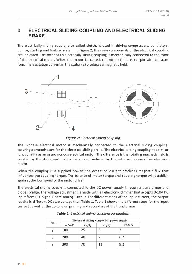
3 ELECTRICAL SLIDING COUPLING AND ELECTRICAL SLIDING BRAKE
The electrically sliding couple, also called clutch, is used in driving compressors, ventilators, pumps, starting and braking system. In Figure 2, the main components of the electrical coupling are indicated. The rotor of an electrically sliding coupling is mechanically connected to the rotor of the electrical motor. When the motor is started, the rotor (1) starts to spin with constant rpm. The excitation current in the stator (2) produces a magnetic field.
Figure 2: Electrical sliding coupling
The 3‐phase electrical motor is mechanically connected to the electrical sliding coupling, assuring a smooth start for the electrical sliding brake. The electrical sliding coupling has similar functionality as an asynchronous electrical motor. The difference is the rotating magnetic field is created by the stator and not by the current induced by the rotor as in case of an electrical motor.
When the coupling is a supplied power, the excitation current produces magnetic flux that influences the coupling torque. The balance of motor torque and coupling torque will establish again at the low speed of the motor drive.
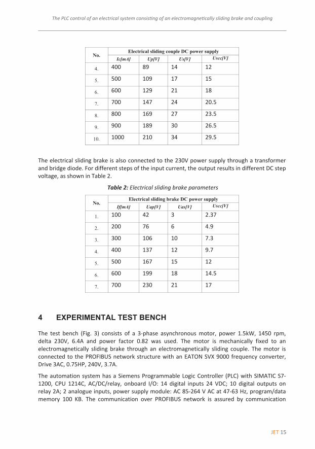
The electrical sliding couple is connected to the DC power supply through a transformer and diodes bridge. The voltage adjustment is made with an electronic dimmer that accepts 0‐10V DC input from PLC Signal Board Analog Output. For different steps of the input current, the output results in different DC step voltage than Table 1. Table 1 shows the different steps for the input current as well as the voltage on primary and secondary of the transformer.
Table 1: Electrical sliding coupling parameters
No. Electrical sliding couple DC power supply
Ic[mA] Up[V] Us[V] Uscc[V]
1. 100 25 3 3
2. 200 48 7 6.2
3. 300 70 11 9.2
JET 15
The PLC control of an electrical system consisting of an electromagnetically sliding brake and coupling The PLC control of an electrical system consisting of an electromagnetically sliding brake and coupling 5
‐‐‐‐‐‐‐‐‐‐
No. Electrical sliding couple DC power supply
Ic[mA] Up[V] Us[V] Uscc[V]
4. 400 89 14 12
5. 500 109 17 15
6. 600 129 21 18
7. 700 147 24 20.5
8. 800 169 27 23.5
9. 900 189 30 26.5
10. 1000 210 34 29.5
The electrical sliding brake is also connected to the 230V power supply through a transformer and bridge diode. For different steps of the input current, the output results in different DC step voltage, as shown in Table 2.
Table 2: Electrical sliding brake parameters
No. Electrical sliding brake DC power supply
If[mA] Uap[V] Uas[V] Uscc[V]
1. 100 42 3 2.37
2. 200 76 6 4.9
3. 300 106 10 7.3
4. 400 137 12 9.7
5. 500 167 15 12
6. 600 199 18 14.5
7. 700 230 21 17
4 EXPERIMENTAL TEST BENCH
The test bench (Fig. 3) consists of a 3‐phase asynchronous motor, power 1.5kW, 1450 rpm, delta 230V, 6.4A and power factor 0.82 was used. The motor is mechanically fixed to an electromagnetically sliding brake through an electromagnetically sliding couple. The motor is connected to the PROFIBUS network structure with an EATON SVX 9000 frequency converter, Drive 3AC, 0.75HP, 240V, 3.7A.
The automation system has a Siemens Programmable Logic Controller (PLC) with SIMATIC S7‐1200, CPU 1214C, AC/DC/relay, onboard I/O: 14 digital inputs 24 VDC; 10 digital outputs on relay 2A; 2 analogue inputs, power supply module: AC 85‐264 V AC at 47‐63 Hz, program/data memory 100 KB. The communication over PROFIBUS network is assured by communication

16 JET
Georgel Gabor, Adrian Traian Plesca JET Vol. 11 (2018)Issue 4
6 Georgel Gabor, Adrian Traian Plesca JET Vol. 11 (2018) Issue 4
‐‐‐‐‐‐‐‐‐‐
processor communication module CM 1243‐5 for connection of SIMATIC S7‐1200 to PROFIBUS as DP master module.
Figure 3: Test bench
The software used for configuration of the automation system is SIEMENS TIA Portal V13. It comprises Step 7 software for PLC programming and WinCC for HMI design. STEP 7 (TIA Portal) is the engineering software for configuring the SIMATIC controller families S7‐1200, S7‐1500, S7‐300/400 and software controllers (WinAC). WinCC (TIA Portal) is engineering software for configuring SIMATIC Panels, SIMATIC Industrial PCs, and Standard PCs with the WinCC Runtime Advanced or the SCADA System.
The PLC programming includes the configuration of PROFIBUS communication between PLC and variable frequency drive, hardware configuration, and the program. The data between PLC and HMI are stored in Data Blocks.
Figure 4: PLC programming

JET 17
The PLC control of an electrical system consisting of an electromagnetically sliding brake and coupling The PLC control of an electrical system consisting of an electromagnetically sliding brake and coupling 7
‐‐‐‐‐‐‐‐‐‐
To vary the excitation current on the electrical sliding brake, the analogue output of the Siemens signal board is used. Signal boards are connected directly to the front of the SIEMENS CPU. They can be used where space is limited or if only a few additional inputs/outputs are required. While increasing the brake current by INC and DEC buttons, the torque of the brake will increase obtaining the family of the curves in Figure 5. The force is measured by an electronic scale.
Figure 5: Torque vs RPM
5 CONCLUSIONS
Testing of the speed and torque of electrical system has been performed in this study by using a Profibus industrial automation network. This study has shown that the control and monitoring of an electrical system by using PROFIBUS yields high performance. This situation has been realized with the data obtained from the test bench. The graphics show the dependency of the torque by excitation current of the coil of the electrical sliding brake for different test cases. This experiment can be improved by controlling the current PLC technology over the Internet.

18 JET
Georgel Gabor, Adrian Traian Plesca JET Vol. 11 (2018)Issue 4
8 Georgel Gabor, Adrian Traian Plesca JET Vol. 11 (2018) Issue 4
‐‐‐‐‐‐‐‐‐‐
References
[1] PROFIBUS Standard Part 1 and 2, DIN 19 245, German Institute of Normalization, 1995
[2] Hongjun Chen, Xiaohua Zbang, Xuerui Zbang Application of Profibus to industrial automation”,Siemens Automation Training Center, Harbin (SA TCH), Department of Electrical Engineering, Harbin Institute of TechnologyHarbin, 150001, P. R. China, 1998
[3] C. Yılmaz and Y. Korkmaz, Y. Sönmez and L. Bulut, M. Fatih Işık: Controlling of a 3‐Phased Asynchronous Motor over Profibus, International Journal of Electronics and Electrical Engineering Vol. 4, No. 1, February 2016
[4] Specification for PROFIBUS Device Description and Device Integration, Volume 1: GSD, Order No. 2.122, Version 5.1, July 2008
[5] Specification for PROFIBUS Device Description and Device Integration , Volume 1: GSD, Order No. 2.122, Version 5.1, July 2008
[6] Tamal Aditya, Gyan: Research to study Variable Frequency Drive and its Energy Savings, Vihar School of Engineering and Technology, International Journal of Science and Research (IJSR), India Jaipur‐302025, India, Volume 2 Issue 6, June 2013
[7] Hongjun Chen, Xiaohua Zbang, Xuerui Zbang: , Application of Profibus to Industrial Automation, International Journal of Electronics and Electrical Engineering Vol. 4, No. 1, February 2016, Research article, IFAC Proceedings Volumes, Volume 31, Issue 25, September 1998, Pages 157‐161