The Personal Satellite Assistant: An Internal Spacecraft ... · PDF fileThe Personal Satellite...
16
.'i _.. Ii I The Personal Satellite Assistant: An Internal Spacecraft Autonomous Mobile Monitor Gregory, A. Dorais and Yuri Gawdiak NASA Ames Research Center MS 269-2 Moffett Field, CA 94035 650-604-4851 gdorais @arc.nasa.gov, ygawdiak @arc.nasa.gov Abstract--This paper presents an overview of the research and development effort at the NASA Ames Research Center to create an internal spacecraft autonomous mobile monitor capable of performing intra-vehicutar sensing activities by autonomously navigating onboard the International Space Station. We describe the capabilities, mission roles, rationale,- b_igh-level functional-requkements,-and design - chal!enges--for-an-au_nomous-mobile-moniror: The--rapid prototyping desig-n methodology used, in which five prototypes of increasing fidelity are designed, is described as well as the status of these prototypes, of which two are operational and being tested, and one is actively being designed. The physical test facilities used to perform ground testing are briefly described, including a micro-gravity test facility that permits a prototype to propel itself in 3 dimensions with 6 degrees-of-freedom as if it were in an micro-gravity environment. We also describe an overview of the autonomy framework and its components including the software simulators used in the development process. Sample mission test scenarios are also described. The paper concludes with a discussion of future and related work followed by the summary. TABLE OF CONTENTS 1. INTRODUCTION .................................................. 1 2. PSA RATIONALE ............................................... 2 3. FUNCTIONAL REQUIREM]_NTS .......................... 4 4. PSA PROTOTYPES AND TEST FACILITIES ........ 6 5. AUTONOMY FRA_VIEWORK AND SIMULATORS .. 9, 6. SAMPLE MISSION TEST SCENARIOS ............... 12 7. FUTURE WORK ................................................ 13 8. RELATED WORK ..................................... : ........ 14 9. SUMMARY ........................................................ 15 ACKNOWLEDGMEIVrs .......................................... 15 REFERENCES ........................................................ 15 1 U,S. Government work not protected by U.S. copyright 2 2003 IEEEAC paper # 1091 1. INTRODUCTION The Personal Satellite Assistant (PSA) project is a NASA research and development activity to design an intelligent, small, free-flying, remote-sensing vehicle capable of autonomously navigating in three dimensions within a pressurized;-micro-gravity-envkov, mentc diagnosing-systems in--its envir onment-cand-interaetin_with-people -such -khat-it-is - useful, easily understood, and easily commanded in a minimally time-consuming manner. The primary operating environment is the International Space Station (ISS), but other environments include the Space Shuttle and future manned spacecraft, such as one designed to carry a crew to Mars. The PSA has various environmental and equipment sensors as well as audio/video human-interface devices. It can be remotely commanded at various levels of autonomy and also can be commanded by simple speech commands and human motions. Mission Roles The two primary mission roles of the PSA is being designed to address are to improve spacecraft crew productivity and to decrease mission risk by serving as part of an integrated spacecraft systems health management system. Spacecraft health-management support role--the PSA will provide mobile monitoring, diagnosis, and communication capabilities. The PSA is being designed to supplement the spacecraft's Environmental Control Life and Support System by measuring temperature, pressure, humidity, and various gas levels (e.g., oxygen, COy and recording a visual log as it traverses the spacecraft. The PSA will help diagnose and calibrate spacecraft sensors, temporarily replace faulty environmental sensors, generate acoustic, temperature, and gas concentration maps, locate gas and fluid leaks, filter atmospheric particles, as well as characterize heat sources with its infrared camera. ? r r https://ntrs.nasa.gov/search.jsp?R=20020091930 2018-05-11T11:43:14+00:00Z
Transcript of The Personal Satellite Assistant: An Internal Spacecraft ... · PDF fileThe Personal Satellite...

.'i _..Ii I
The Personal Satellite Assistant:
An Internal Spacecraft Autonomous Mobile Monitor
Gregory, A. Dorais and Yuri GawdiakNASA Ames Research Center
MS 269-2
Moffett Field, CA 94035650-604-4851
gdorais @arc.nasa.gov, ygawdiak @arc.nasa.gov
Abstract--This paper presents an overview of the research
and development effort at the NASA Ames Research Center
to create an internal spacecraft autonomous mobile monitorcapable of performing intra-vehicutar sensing activities by
autonomously navigating onboard the International Space
Station. We describe the capabilities, mission roles,
rationale,- b_igh-level functional-requkements,-and design
- chal!enges--for-an-au_nomous-mobile-moniror: The--rapidprototyping desig-n methodology used, in which five
prototypes of increasing fidelity are designed, is described
as well as the status of these prototypes, of which two are
operational and being tested, and one is actively being
designed. The physical test facilities used to perform ground
testing are briefly described, including a micro-gravity test
facility that permits a prototype to propel itself in 3dimensions with 6 degrees-of-freedom as if it were in an
micro-gravity environment. We also describe an overview of
the autonomy framework and its components including the
software simulators used in the development process.
Sample mission test scenarios are also described. The paperconcludes with a discussion of future and related work
followed by the summary.
TABLE OF CONTENTS
1. INTRODUCTION .................................................. 1
2. PSA RATIONALE ............................................... 2
3. FUNCTIONAL REQUIREM]_NTS .......................... 4
4. PSA PROTOTYPES AND TEST FACILITIES ........ 6
5. AUTONOMY FRA_VIEWORK AND SIMULATORS .. 9,
6. SAMPLE MISSION TEST SCENARIOS ............... 12
7. FUTURE WORK ................................................ 13
8. RELATED WORK ..................................... :........ 14
9. SUMMARY ........................................................ 15
ACKNOWLEDGMEIVrs .......................................... 15
REFERENCES ........................................................ 15
1 U,S. Government work not protected by U.S. copyright2
2003 IEEEAC paper # 1091
1. INTRODUCTION
The Personal Satellite Assistant (PSA) project is a NASA
research and development activity to design an intelligent,
small, free-flying, remote-sensing vehicle capable ofautonomously navigating in three dimensions within a
pressurized;-micro-gravity-envkov, mentc diagnosing-systems
in--its envir onment-cand-interaetin_with-people -such -khat-it-is -
useful, easily understood, and easily commanded in a
minimally time-consuming manner. The primary operatingenvironment is the International Space Station (ISS), but
other environments include the Space Shuttle and future
manned spacecraft, such as one designed to carry a crew to
Mars. The PSA has various environmental and equipmentsensors as well as audio/video human-interface devices. It
can be remotely commanded at various levels of autonomy
and also can be commanded by simple speech commandsand human motions.
Mission Roles
The two primary mission roles of the PSA is being designed
to address are to improve spacecraft crew productivity andto decrease mission risk by serving as part of an integrated
spacecraft systems health management system.
Spacecraft health-management support role--the PSA will
provide mobile monitoring, diagnosis, and communicationcapabilities. The PSA is being designed to supplement the
spacecraft's Environmental Control Life and Support
System by measuring temperature, pressure, humidity, and
various gas levels (e.g., oxygen, COy and recording a visual
log as it traverses the spacecraft. The PSA will helpdiagnose and calibrate spacecraft sensors, temporarily
replace faulty environmental sensors, generate acoustic,
temperature, and gas concentration maps, locate gas and
fluid leaks, filter atmospheric particles, as well ascharacterize heat sources with its infrared camera.
?r
r
https://ntrs.nasa.gov/search.jsp?R=20020091930 2018-05-11T11:43:14+00:00Z

Crew productivity role--the PSA will provide several
support capabilities including: remote Visual monitoring andtask recording, video and data display, payload & core
system knowledge management terminal, inventory location
and tracking, just-in-time training, and standard PDA
functions (schedule, notes, activity lists, and calcuIation
functions). These capabilities will directly support on-orbit
crews in the daily execution of payload experiment and coresystem tasks.
To support the flight crews, ground crews, and payload
scientists, the PSA can be used for monitoring andcommunication using its audio and video sensors as well as
perform videoconferencing and display a variety data on its
LCD screen. The PSA will allow ground crews and
scientists to be virtually located inside the spacecraft.Moreover, the PSA's autonomy capabilities will allow
remote users to interact with the crew and spacecraft in ahuman-centered way while providing real-time data
_collection and communication.
The ISS, for example, is an extremely ambitious operationalenvironment for the crew (3-6 members) with tens of
thousands of inventory items to track within it and hundreds
of experiments to manage covering a wide spectrum ofscience disciplines. The overall productivity of the ISS can
be increased by automating or otherwise reducing the crew
time required to perform tasks as well as enhancing orenabling science activities that would otherwise not be
performed due to insufficient crew time by,means of a PSA.
This paper describes the PSA project rationale, high-level
functional requirements, project implementation approachincluding a description of five prototypes and their test
facilities, current project status, autonomy technologycomponents, test mission scenarios, and future missiongoals.
2. PSA RATIONALE
The impetus for the PSA project is to develop an intelligentsystem that increases crew productivity and reduces risk formanned missions. It was originally an element of the NASA
Cross-Enterprise Technology Development program and has
subsequently been adopted by the Intelligent Systemsproject in the NASA Computing, Information, and
Technology program, which primarily focuses on enhancingits autonomy, and the NASA Engineering Complex Systems
(ECS) program, which is responsible for the overalldevelopment effort to raise its technological readiness level.
The ECS program was formulated by NASA to address
--grooving concems._about- the. agency-'-s abilit-y -to develop,
operate, and maintain the complex systems required to meetour current and future mission objectives.
During the program formulation phase the ECS programidentified four common problem classes associated in mostNASA systems:
1. Limited system and trade space analysis capabiIities
2. Poor understanding of system, human andorganizational risk
3. Incomplete knowledge acquisition andcommunication
4. Inadequate state assessment and brittle controlstrategies
Based on these problem classes, the ECS program
developed a three-pronged W-BS solution approach:
1. System Reasoning & Risk Management
2. Knowledge Engineering for Safe Systems
3. Resilient Systems and Operations
- -The-PSA- project -is--part of- _e- -Resilient- Systems- and- -
Operations thrust. PSA's main focus is addressing problemclass number four: "Inadequate state assessment and brittle
control strategies", but it also addresses problem class
number three "Incomplete knowledge acquisition andcommunication."
The PSA near term objectives are organized around
addressing these two problem areas during the operationsand maintenance phases of a mission lifecycle. Within these
phases, the PSA provides support in two distinct parts of in-
flight spacecraft system operations: spacecraft health
management and crew productivity. The spacecraft healthmanagement goal relies primarily on developing advanced
Fault Detection, Isolation, & Recovery (FDIR) technologies
for Environmental Systems. The crew productivity goal
relies primarily on advanced Knowledge Management (KM)technologies. In addition, underlying many of the advanced
FDIR and KM technologies are advanced autonomy
technologies to reduce the user time and complexityrequired to benefit from the FDIR and KM technologies.
Fault Detection, Isolation, & Recovery
In this area, system deSigners have to make difficult trade-
offs on the appropriate number, type, location, andredundancy of environmental sensors to meet critical life
support requirements. In spacecraft such as the ISS and
Space Shuttle, the Environment Control & Life SupportSystem (ECLSS) Crit. 1 system is required to meet two fault
tolerant requirements. Part of meeting these requirements
may be achieved through redundancy. Redundancy ingenerakhas_a_significant_penalty_An.terms_of_weight,_volume,_ .....
and cost. Additionally, it is very susceptible to common
cause failures. The PSA's mobility capability can have a
significant impact on the redundancy strategy by providingsensing in an autonomous & dynamic fashion. Instead of
having to hardwire a large quantity, of sensors that might

neverbeusedandabsorbingtheassociatedweight,volume,developmenttime,andcosthitsin aspacecraftdesign,thePSA "on-demandredundancy"significantlylowersthenumberof overallsensorsthatarerequiredtobeinstaIled.Additionally,themobilenatureof thePSAplatformallowsfor amorethoroughandsystematicmonitoringof agivenspacecraftmoduletherebydetectinganomaliesandfailureswithahigherprobabilitythanagivenfixedsensor.
ThespecificPSAFDIRfunctionalgoalsinclude:
Fault Detection-
. Monitoring of environmental gases: (e.g., oxygen, CO:),temperature, pressure, and humidity (and keeping crewmembers informed as to when changes may cause healthrisks)
• Detecting and monitoring internal structural flaws orfailures: chicks and leaks
• Off-gassing of harmful chemicals: hydrazine, others
; Sensor failhres/caiib-ratidn e_6i'S
Isolation-
. Pinpointing the location of gas leaks or heat sources
• Pinpointing the location of structural flaws or failures
• Identifying specific failed sensors
Recovery-
. Taking over the role of a failed fixed sensor
• Calibrating a fixed sensor after it has been replaced
• Aug-meriting the monitoring of the environment in a givenlocation by operating multiple PSA's in the region (suchas on the Mir Space Station after the fLres were put out--additional sensors at locations affected by the fire would
have been helpful to make sure hot spots were closelymonitored or if new flare ups occurred, they were quicklyidentified).
The FDIR environmental capabilities of the PSA are
applicable to both core and payload systems. Beside the
obvious implications for crew and payload safety, there isalso the key aspect of ancillary data quaIity for science
payload research. During certain payload experiment phasesadditionally monitoring can be delivered on demand to
improve the quality/resolution of the ancillary environmentaldata being collected.
Another FDLR design goal for the PSA is for it to be able to
intelligently interact with the crew, spacecraft systems (e.g.,
ECLSS), and other multiple PSA's. The mobility aspect ofthe PSA enables flexible verification and optimization of
tasks for deaiing with environmental system failures.
back-up) 3 systems. Ground and flight crews can use the
PSA's as virtual extensions of their senses enabling them to
cover more options and collect information faster than by
using traditional resources. Moreover, multiple PSA's can
be coordinated to cover more space quickly in hunting
down, isolating, and recovering from failure scenarios.
Knowledge Management
The PSA KaM functional goals cover: crew personal assistantfunctions (schedules, notes, data access, etc.), core and
payload procedure support, inventory tracking, training, datarecording, and maintenance. These features allow the crew
to leverage cutting edge information technologies to
improve their own productivity. The PSA will tap into boththe core and payload networks and will be able to interact
with crew via keyboard and voice recognition interfaces.These inputs and the PSA's intelligence will allow it to
function in complementary, parallel, and independent modes
with the crew. Examples include "look ahead" capabilitiesinVdi,Ting--_h6_king brew rhembers sch-eauie_,--cii_rent
..... io_5/ffd-n_-E6_ ne_[ activi/y re-_tiir-e_iits, spacecraf/-m-oBg-& ..........
stares, and doing inventory checks to make sure appropriateresources are available for the next task at hand. The
training, maintenance, procedure support functions will
heavily leverage the PSA multi-media features including:audio and video I/O. These components will enable video
conferencing capabilities allowing remote personnel todynamic interact with the onboard crew. Remote
manipulation of the PSA will allow collaborative
inspections, procedure support and experiment consultationsto take place while freeing both of the crewmember's hands
to focus on execution of a given task in the position and atthe location desired.
..... paS_gdgd£ffffs-ystems can g_6-th_ P-SATo-VeYffy common fgl_ .....
positive sensor feedback before having to activate expensive
(power-wise, schedule) and (sometimes more dangerous3 Going to baclci_p systems often entail new procedures, new
systems being named on for the first time for extensive useand other embedded risks
The PSA assigned to astronaut Mary onboard the
International Space Station wakes her up to her favoritesong. As Mary wakes up, the PSA uses its wireless network
access to status networks and servers to provide a user-prioritized list of information Mary likes to have in the
morning: action items, ISS Iocation and mode, any overnightanomalies, e-mail from home, and world news. As sheexercises and eats breakfast, the PSA briefs her on her last
in-space physical as well as preps her for the first
experiment of the morning. The PSA reads the procedures,
A Day in the Life of the Personal Satellite Assistant
Consider the following hypothetical scenario where a PSA
interacts with a crewmember and ISS equipment andsystems throughout the day. This scenario showcases the
range of PSA functionality and flexibility to support on orbitoperations.

her groundnotes,andthe biographyon the PrincipleInvestigator(PI)oftheexperiment.
enablesthegroundto haveextrasensordatawithoutrequiringcrewtimeorincreasingrisktothecrew.
AssheandthePSAmovetotheexperimentstation,thePSAnoticesaninconsistencybetweenitsenvironmentalsensorsandthe station's in the Node 2. An auxiliary PSA isrequested by the ground crew to verify the readings.
Mary's morning experiment involves the use of an tSS
glovebox: a sealed, windowed environment with two gloves
attached to a wall that permits a crew member to use both
hands to manipulate objects in the environment withoutbreaking the seal. Mary's PSA's control is transferred to the
ground to allow the PI to be virtually present as Maryconducts the experiment on orbit. The PI is abIe to fly
around the operation and Nve real-time consultation andevaluations while Mary is free to use both hands to conduct
the tasks. The PI also takes advantage of the PSA beingaround and requests for additional ancillary environmental
-data to be collected by the PSA and inte_ated into the
- ---experiment logs.
After the docking, the PSA returns to Mary and supports her
through the rest of the day. After Mary and the rest of the
human crew goes to sleep, the PSA recharges in preparation
for its assigned patrol duty. It's given several priority areasto monitor where recent mishaps have occurred; a fire and a
pressure leak are high on the ground crew's list to monitor.
As the PSA moves out on its evening patrol, it passes byanother PSA system at the sensor location that it had
identified earlier as having a calibration error. The sensor in
question has since failed. The other PSA is now providingsubstitute sensing until a new sensor is installed.
3. FUNCTIONAL REQUIREMENTS
In order to develop a system that can meet the goals
previously described, we defined a number of requirements.
. Ln___is_paper, we w il!_ disc_u_s_s.A_f_e-w_of___.th_e_high_er-!e-velfunctigna!.requirements that may be of particular interest. _. _
As Mary finishes up the experiment ahead of schedule, the
PSA notifies Mission Control who updates her schedule.The PSA checks the latest updated schedule for the next task
to make sure all the resources are available for Mary to
perform it. The PSA discovers that a wrench is missing for
the core system filter replacement task next on Mary's listand asks Mary for permission to initiate a search. Mary
gants permission and the PSA initiates a search pattern forthe wrench using RFID to identify and verify inventory
within the station. The PSA fleet commander, an intelligent
server monitoring and supporting all the PSA's, is notifiedof Mary's PSA inventory activity and dedicates two more
unassigned PSA's to help conduct the inventory sweep. Thethree PSA's working together institute an efficient search
pattern. The wrench is quickly found in one of the newmodules and the crew is notified of the location and the
inventory database is updated.
Requirement Z----create a self-contained portable device withenvironmental sensors, computational capabilities to analyze
the data and perform diagnoses, and a display for viewingsensor data. The sensors are to function inside the ISS and
similar operating environments. The high priority sensors
include those that measure local temperature,, atmospheric
pressure, humidity, and gas concentrations including O 2 andCO z. Lower priority sensors include visible-light still and
motion cameras, thermal imager, Geiger counter, NDIR
spectrometer, electromagnetic detector, RFID tag detectorfor inventory management, microphone, and a directional
acoustic detector array for localizing emissions. Our first
attempt at designing a system that met this requirement
resulted in a "breadboard system" that could conceivablyhave been packaged into a system similar to the Star Trek®
"tricorder." However, additional requirements caused us toabandon the tricorder paradigm.
As Mary and her PSA approach their next task, the PSA,
constantly monitoring real-time status data and Mary'spreferences, detects an opportunity event: a hurricane has
developed over Cuba and Mary likes to monitor them and
take pictures when she can. Since the next task is a 2-personactivity and the second crewmember hasn't arrived yet,Mary gets permission from Mission Control to take time for
her hobby.
During the core system filter replacement, the ground crew
requests permission to use the PSA for a nearby structuralinspection. The astronauts don't need the PSA at the
---moment-and--the pound team uses- the -PS-A'-s- thermal
imaging capabilities to inspect a trouble spot in a nearbydocking node. Nothing is found, but for safety reasons the
ground has the PSA provide additional monitoring
capability during an automated docking procedure. This
4
Requirement 2--stamp the sensor data with the time and a 6-DOF position of the sensors relative to the environment. The
6 degrees-of-freedom (DOF) correspond to X, Y, Z
translations and yaw, pitch, roll orientations relative to aglobal origin. Although meeting the time element of this
requirement can readily be achieved with a clock, satisfying
the position element is challenging. A number of approaches
were examined resulting in two major solution classes. Thefirst requires engineering the environment with active
devices, such a beacons for a local GPS system, or passive
fiducial marks that can be detected by sensors on the device.The second class of solutions includes those that require
motionr-proximity_ and feature detectors on-the-device-that
enabling registering to an internal map. The benefits ofengineering the environment are that it is much easier to
create such a system and the portabl e sensor device can besmaller. The disadvantages include the costs to retrofit,
safety-qualify, and maintain active electromagnetic emission
deviceson ISS;themassof theequipmentrequiredforcoveragethroughoutISS;andthedifficultyin testing.Thebenefits of enabling the device to localize itseIf include
avoiding the disadvantages of enDneering the environment,
not being dependent on external devices for operation, andthe same sensors used for self-localization can be used to
detect dynamic objects not on the PSA's internal map. Thechallenge is that the general ability for a mobile system to
accurately determine where it is and how it is movingrelative to other objects in its environment is one area where
sophisticated computer systems still lag behind the
computational capabilities found in many "simple"
biological creatures. Our current approach is to develop asystem that can do self-localization using a combination of
stereo-cameras to build depth maps and sense motion by
means of optic flow algorithms and fuse this with data froma 6-DOF inertial measurement unit (accelerometers), and
proximity sensors. As necessary, we can mitigate risk byengineering the environment as needed.
...... Requirement 3--"station-keep" on command by maintaininga fixed position and orientation relative to its environment.
Note that the environment, i.e., the ISS, is continually inmotion as it orbits the Earth and performs minor attitude
adjustments. Although the device is useful if it is held by acrewmember or fixed to a surface, the more that can be done
with the device that doesn't require crew time, the better.
For many tasks, crewmembers require both hands so the
sensor device cannot be held. Moreover, some monitoringtasks require taking a measurement at the same location for a
period of time. By satisfying this requirement, a
crewrnember's valuable time can be applied to other tasks.
Requirement 4--navigate to various positions on command,
avoiding static and dynamic obstacles. This requirement canbe viewed as a corollary of requirements 2 and 3. If thesystem already has the sensors, controllers, and actuators to
determine its absolute position and maintain it, enabling it tonavigate requires no additional hardware. Allowing the
system to navigate to various positions again increases theflexibility of the system while decreasing the crew time
required to perform a task. For example, searching for a leakor a measuring gas concentrations throughout a module can
be quite time-consuming. The task is more efficient if it
doesn't require a crewmember to be present even if the tasktakes longer.
Requirement 5--minimize the time required by the crew
while enabling crewmembers to command the system at the
level of autonomy they desire. This requirement is in
keeping with the general principle that crew time is
extremely valuable. In some cases, this means that totally.... autonomous-systems are preferable to manual- systems.
However, there are cases where autonomous systems require
more crew time because the overhead in figuring out how to
command the system to do what is desired autonomously is
greater than doing it manually. A simple example of this
phenomenon involves VCRs where people do not bother to
progam them because it is too complicated and too easy to
make a mistake as opposed to performing the task manually.For more complex systems, in particular the system we are
discussing, this problem is magnified significantly.Consequentially, the requirement is essentially for the
system'to be adjustably autonomous. If necessary, another
system, such as the environmental life support system can
command it to localize a heat source without requiring anycrew intervention. In another task, a crewmember can
command it to go to a certain location and notify him upon
arrival, at which time the crewmember teleoperates the
system as desired. In order to achieve this requirement, the
system must have mLxed-initiative planning, scheduling, and
execution capabilities, and the ability to effectively
communicate with the human operator so the operatorunderstands what the system is doing and why it is doing it,
and the system can interpret what the operator wants and cantranslate it into commands it can execute.
-. Requirement 6--perform continuous active hybrid temporal-
variable diagnostics on its environment and equipment in it.We define a diagnostic system here to be one that
determines the sets of likely states of the system beingdiagnosed consistent with the observations and the model of
the system. A temporal-variable diagnostic system can use
observations that change over time, e.g., recognize trends. A
hybrid diagnostic system is one that can reason given bothcontinuous-valued and discrete-valued observations.
Typically, different approaches are used for continuous and
discrete-valued observations, but many systems require thatboth be reasoned about simultaneously. An active diagnostic
system is one that determines what additional observations
are needed to disambiguate the state of the system being
diag-nosed. For example, consider a system with a HIGH-
TEMPERATURE warning light that is on. Two possiblediagnoses are that the system is indeed overheating or the
temperature sensor is faulty. By actually checking thetemperature of the system, we can then determine more
accurately which of these two diagnoses is more likely
correct. One of the uses of this portable sensor device is aspart of a larger Integrated Vehicle Health Management
(IVHM) system so having this diagnostic capability canincrease the likelihood of early detection and accurate
diagnosis of problems without requiring crew" time.
Although there are several other requirements, these six
functional requirements effectively constrain the space ofpossible solutions. Other notable requirements involve
safety, reliability, and ease-of-use. In particular, a smaller
overall size and longer operation between recharges isbetter.

4. PSA PROTOTYPES AND TEST FACILITIES
,,e PSA project is using an iterative, rapid prototypingdevelopment approach. We started by envisioning the end
product in our minds. In 1998, the project's first year, a
concept modeI, shown in Figure 1, was developed.
The project's primary loci are mitigating risk on issues 1 -3. Issues 4 - 6 are also being worked but at a lower level. In
addition, si_maificant effort was invested in enNneeringprototypes, simulators, and test facilities in order to validate
that we have captured and addressed the salient issues.
For example, spacecraft technoIogy had basically solved the
propulsion and attitude control problem by means of cold-
gas thrusters and reaction wheels. Although reaction wheels
that met our requirements were not commercially available,
we were convinced they could readily be developed. Safety
concerns of having and refueling a high-pressure tank thatwould enable extended operation soon caused us to rule out
cold-gas as a primary means of propulsion. However, it does
remain as a option for a special-purpose PSA, such as one
for exploring depressurized regions of a spacecraft. Instead,
we began examining fans and blowers for propulsion.
Figure 1 - PSA Original Concept Model
With this model, we souaht to answer the question, "if we
could build it, would we want to?" The effort spent indeveloping a handheld mockup was well worthwhile. Not
only did team members find having a physical conceptmodel useful to convey ideas, we found people outside the
project gTasped what we were doing much more readilywhen we used the model in our presentations.
Technology Challenges
Having fleshed out the concept, we began a critical analysisof the problems and risks as well as the needed technologies
currently or imminently available, and those that needed tobe developed. The tall-pole issues we identified were:
1. Continuous 6-DOE position and velocity estimationof the PSA relative to its objects within itsenvironment and the environment, i.e., spacecraft,itself.
2. Adjustably autonomous control, from high-levelmission commands to low-level controller
commands, and the corresponding user-interfaces
3. Active hybrid diagnosis capabilities with multipleagents
4. Safety qualification. Standards for autonomous IVAsinside ISS have not been developed. Other safetyconcerns include autonomous battery recharging andacoustic limits.
5. Onboard wireless bandwidth available.
6. Miniaturization of component technologies whileprotecting against radiation-induced failures. Withthe exception of the LCD, the smaller, the better for asafety and usabilitv.
Unlike most spacecraft, the PSA is required to navigate in
--close-proximity to both static and dynamic objects.Moreover, unlike gound vehicles, the PSA has no "brakes"to stop and safe itself with while it determines where it is
relative to what's around it and what it should do in an
environment that is continually moving. Moreover, simplymoving one meter forward is problematic since the PSA has
no direct way of measuring odometry whereas a ground
"vehicle can move fixed distances by simply counting wheel
rotations. Unfortunately, the error that accumulates byattempting to determine distance traveled by double
inte_ating the measured accelerations is useful only for veryshort distances.
PSA Model 1
As previously discussed in the functional requirementssection, we began looking at using stereo vision and
engineering the environment as possible methods forperforming continuous localization. In addition, we also
began looking at fusing stereo depth maps with proximity
sensors for obstacle avoidance. In order to perform tests, in1999 we developed at 3-DOF testbed called the Model l,
which is shown juxtaposed to the concept model in Figure 2.
In the Model 1 design, no attempt was made to conform to
the packaging eventually required. By equipping the Model
1 with a stereo-vision systems, we are able to performvision-based localization and visual servoing. My means of
a wireless Ethernet, a high-level model-based autonomouscontrol system located on a remote server commands theModeI 1 to execute various missions.

algorithmsthatuseoneto fourstereo-paircameras•TheModel2 wasdevelopedto supportup to fourstereopaircameras, in addition, a 12" sphere was created directly from
C_d) drawings using a stereo-lithography process.
Propulsion and attitude control 6-DOF (X, Y, Z, yaw, pitch,
roll') were achieved using 6 fan pairs located in 6 ducts• Itwould have been preferable to use reaction wheels for
several reasons including they would provide tighter control,
quieter operation, and _eater energy efficiency. However,reaction wheels that met our specifications would have to be
custom built so they were scheduled to be implemented as
part of the Model 3 prototype.
Figure 2 - PSA Concept Model (left) andCa, _,,,,ue, I Prototype _-:-'-"kt iEl.t l )
Low-friction Platter Test Facili o,
To test the Model 1 prototype in 3-DOF (X, Y, yaw) andsubsequent prototypes in up to 5-DOF (vertical translation is
not supported), we have developed a low-friction planer test
facility. It consists of a 12' x 12' _anite table polished and
leveled so that it functions as a smooth, horizontal plane. A12" circular plate was attached to the bottom of the Model 1
on which a small compressor was mounted that pressurizesthe space between the plate and the table. This enables theModel 1 to float on a thin cushion of air as it translates and
rotates on the table propelled by its fans. Above the table, adigital camera was mounted so that most of the table is
within its field of view. Three LED's were mounted on the
top of the Model 1 so that machine vision software can track
the actual location of the Model l, i.e., provides _ound
truth. We use this external localization capability to measurethe accuracy of the onboard position estimation system. In
addition, for unit test purposes we can configure the onboard
control system to use the externally-calculated position datastream as feedback to achieve its commanded position andvelocity, trajectories.
PSA Model 2
While the Model 1 was being tested, development of a 6-
DOF Model 2 and an accompanying 6-DOF micro-gravi b'test facility was underway. We were well aware that the
position and velocity estimation problem in a 3-DOF system
was much simpler than in a 6-DOF system. The existing
algorithms we examined that work fine in a 3-DOF systemdid not work at all in a 6-DOF system, primary due to thelikablility to d{samb_uate motion between the various
de_ees of freedom. To address this, we began a joint-research effbrt with SRI International to extend elements of
3-DOF vision systems it developed to 6-DOF. We
developed a vision testbed that supports testing vision
Figure 3 - PSA Model 2 supported on pitch & yaw gimbal
The Model 2 became operational in 2001 and currently isbeing tested on a pitch & yaw _mbal shown in Figure 3. It
is 12" in diameter to enable the use of commercially
available components as much a possible and to give spaceto make changes after it was constructed. For example, theprimary core is comprised of a PC104 stack of boards. The
gimbal is mounted on a pressurized plate, which permits it to
float on the table in the low-friction planer test facility
similar to the Model 1, permitting motion in 4-DOF.
The Model 2 has a 3.8" diag. LCD located at in the center of
its front lower hemisphere. The LCD can be used to displaydata generated Iocally as well as data received via its
wireless network, e.g., text terminals, images, schematics,
videos, etc .... The LCD was purposefully designed to be
small since we expect the flight version of the PSA to besignificantly smaller where fitting a large LCD is
problematic. The smaller the display, the closer the user
must be to it. However, users generally prefer larger displaysand the PSA wi!! attempt to maintain a safe distance _om a
user that-gets too c[ose.
Micro-gray'it)., Test Facili__,
The Model 2 is also being tested in a micro-_avity' testfacility, currently under development. Currently, the micro-

gravity test facility supports 4-DOF motion (X, Y, yaw.
pitch). The Z-axis, which is currently undergoing stand-
alone tests, and a 3-DOF gimbal, which permits yaw, pitch,
and roll motion, are expected to be operationaI soon.
The micro-_avity test facility is roughly 36' long, 13' wide,
and 8' high. This is large enough so that the interior volume
of any one ISS module can fit underneath. It consists of a 3-
DOF (X,Y,Z) bridge-crane-like mechanism that supports a
passive 3-DOF gimble that permits free spinning in yaw,
pitch, and roll. A bridge moves up and down the length of
the facility'. The trolley moves along the bridge permitting
the trolley to move to any (X,Y) coordinate in the test
facility. A crane on the trolley raises and lowers a gimbal
attached to it. The object to be tested is mounted in the
gimbal and balanced so that it freely spins and doesn't
"wobble." The micro-gravity test facility can be operated in
the following four modes.
!. Velocity mode. This is r_he most common mode used
to con_o! bridge cranes. W_..en a crane axis motor is
activated, it runs at a specified velocity until stopped.
2. Position mode. The crane servos to a specified
(X,Y,Z) location then stops.
3. Force mode. The commanded force increases or
decreases the crane motor velocities. When no force
is commanded the crane motors continue at a
constant velocity.
4. Force-neutralization mode. Instead of commanding
motor forces, sensors located on the trolley and
gimbal sense translation forces (X,Y,Z) acting on the
gimbal payload and these sisals are interpreted by
the crane motors as force commands. The Z-axis
signal is modified so that the constant force of gravityis zeroed out.
Figure 4 - PSA Model 3 Preliminary Concept Drawing
The most notable difference in the Model 3 compared to the
Model 2 is the use of two blowers and four reactions wheels
for propulsion and attitude control. Each blower, one is
located at the top _--_ the _*_",ot**e, at the _- "*_ = z, ...._1" 1 l_J" uO LLVIII_ _- XllaU_ 1.
uuuugu tu_ a_.LuaLeu veJ_L_ Lv la_up_t mc PSA. ,-,.L .... u--...-:_
possible to control yaw, pitch, and roll with only three
reaction wheels a fourth reaction wheel enables momentum
to be shifted among reaction wheel. Shifting momentum
conserves energy that would otherwise be lost when a
reaction wheel saturates. Saturation occurs when a reaction
wheel can no longer provide torque because the rotational
velocity of the wheel cannot be increased ffn-ther. Another
notable difference in the Model 3 is that it will include
additional environmental sensors, including a thermaI
imager. When completed, the Model 3 will be oversized and
not space qualified, but otherwise will have all the
capabilities vm........ ,,_a for the fi,¢,,t;_,hmodel.
PSA Model 4
Both force modes (3 & 4) can be used to simulate micro-
_avity as well as various fractions of Earth gravity.
However, the force neutralization mode is the primary
micro-gravity simulation mode. Either a human operator or
the PSA Model 2 can be used to operate the micro-gravity
test facility, in any of these modes.
PSA Model 2
While testing continues on the Model 2, the preliminary
design of the Model 3, shown in Figure 4, is nearing
completion. The Model 3 is scheduled to be operational by
the end of 2003.
if it is deemed important for risk mitigation, the Model 3
The primary focus of the Model 4 development is to
miniaturize the prototype and increase its energy efficiency
as opposed to adding capabilities. A 12" sphere is
uncomfortably large for people to interact with and its
associated mass decreases its operational time between
recharges. Moreover, increased mass generally increases the
risk of unsecured objects causing injury or damage. The
development cost of the sphere increases significantly as the
sphere diameter decreases. Moreover, the user benefit
gained diminishes as the size decreases. Currently, we are
targeting the Model 4 to be 8-9" in diameter.
The blowers and reaction wheeIs used in the Model 3 were
specifically designed so that they can be scaled down
without undesirable side effects. The most expensive task of
will be tested onboard a KC-135 aircraft performing a series the Model 4 development is expected to be moving from the
of dives 59 simulate sh_QLt periods of micro-gravity as u_sed COTS-electronics_ in particular the PCI04 boards, used in
by astronauts for trainings. Otherwise, these tests wilI be the Models 1-3, to a custom chip set.fin-st performed using the Model 4.
The largest non-structural component of the Model 4 by
volume and mass will be its battery. We have begun
researching various approaches to address this including
8

using batteries as structural components, e.g., the external
shell itself. However, concentrating the mass density in the
sphere center reduces the energy required to turn the PSA.
Moreover. there are operational advantages to quic_y being
able to replace a batter)' rather than waiting for it torecharge. ,another design consideration is that batteries that
can be charged and discharged quickly tend to not hold as
much energy as ones that don't. Using the moment,cn'p_wheels, we will have the ability to use excess momentum to
recharge batteries, acting somewhat like a self-winding
watch, but this will be limited by the maximum recharge rate
of the batteries. Moreover, the critical propulsion measure ishow quickly can the PSA stop, which is a function of its
mass, velocity, and the maximum battery discharge rate.Initially. a hybrid batter), approach seems to hold the mostpromise.
PSA Model 5
The Model 5 is targeted as the in-st PSA prototype to be
.... o.,,_ a s_,.e_.,,,,_, primary design focus.tlb
..,:u_,,mbe, tO _uu,c_...........uut_Lauumg='_:_iss'd_S rclatcu_'.... to _'_'_tlLOrlL
qualification, which include component off-gassing,
radiation shielding, battery safety, meeting acoustic and
electronic noise standards, and other safety issues. In
addition, the Model 5 is expected to incorporate designchanges resulting from tests performed on the Model 4.Given funding and schedule constraints as well as user
feedback on the usability of the Model 4, we may alsoattempt to reduce the diameter of the Model 5 to as small as
_.
5. AUTONOMY FRAMEWORK AND S/3,!ULATORS
An autonomy framework designed to address the previously
discussed operational requirements has been developed andis depicted in Figure 5. The same softs,are is used to
command the PSA Model 1 and Model 2 as well as the PSA
in simulation. Care was taken to design and implement thisframework so that it is applicable to a wide range of free-
flying vehicles and are exploring applying it to otherdomains, e.g., UAV.
The user can issue commands to the PSA through the CrewGUI. ,Mso, the user can issue verbal commands to and
receive spoken notifications generated by the PSA via a
headset. Other external systems, including other PSA's, candirectly and simultaneously issue commands to the PSA,
which will attempt to resolve any conflicts. Finally, the PSAitself can generate commands in keeping with its high-levelgoals and periodic task schedule.
The PSA autonomy framework is comprised of a number of
control eiements, W_idh ai-e represented _ boxes in Fig,_e5. The current implementation is distributed over three
processors, as indicated by the dashed boxes, which are
connected by wireless Ethernet. Each of these three
subsystems and the control elements it contains is briefly
discussed below. The entire autonomous system is discussed
in geater detail in [1]. Note that the framework design andmany of its elements draw their heritage from the model-
based, goal-achieving, temporally-flexible NASA "Remote
Agent" autonomy software flight-validated on the DeepSpace One spacecraft in 1999 [2].
Onboard Control Cvstem Elements
The onboard control system is responsibIe for sensing,
sensor analysis (e.g. object fault recognition), stateestimation (e.g., position estimation), hardware actuation
e ,, currents), and real-time reactive control (e.g.,._,., motor
obstacle avoidance), generaily with sub-second latency. Thissystem is designed to enable IocaI operation of the PSA evenwhen' communication with the off-board system is lost,
which may occur during a flight emergency.
Local Path Planner--generates a trajectory between two
waypoints that takes into account locally sensed obstacles
When given a third waypoint, the traject0ry passes through[h_ secona _@'pdiht. The iocai _a=-tii-_ianne-{ pe-rf0rms
limited trajectory repair in case of a path plan failure, e.g.,blocked path.
High-level controllers--primary responsibility is to translate
the trajectory into a sequence of 6-DOF [position, velocity,,and acceleration] setpoints for the low-level controllers.
Low-level controllers--primary responsibility, is to translatethe setpoints into motor force commands to achieve thespecified PSA motion.
lgJ ......... _t.,,c4 ,_,,d,vu,_--me sensors and actuators with theirl O.el
associated drivers. These include fan motor controllers,
stereo cameras, environment sensors, proximity sensors, andan LCD.
Monitors--signal processing loops that abstract the data
generated by the sensors. They run from being as simple as
indicating that a proximity sensor has fired to continually
calculating 6-DOF positions and veIocities by fusing the
stereo camera, 6-DOF accelerometers, and proximitysensors.
Communication Manager--responsible for managingmessage traffic and executing certain message handIers.Serves same role in both off-board systems.
Off-board Autonomy System
The off board autonomy system is responsible for high level
autonomous control including inter-agent com_municationand coordination (including humans), goal management,
decomposing high-level tasks (planning) into commands that
can be executed by the onboard control system, e.g.,
way'point commands, constraining task times (scheduling),
command sequencing (pIan execution), and reasoning about

Off-board
Autonomy
System
(Server)
e.g., direction
eg., waypoint
eg., velocities e.g.location
e g., motol
, Qn_b£ard s -I-Control
System
(PSA)
........................................................
wireless
Ethemet
eg., commands,
telemetry
Figure 5 - PSA Autonomy Framework
sensor data provided by the onboard control system, e.g., for
diagnosis, and for plan repair, e.g., onboard control system
is unable to achieve a waypoint. Architecturally, this systemcould be integrated onboard the PSA. It is off-board to
peL-mAk increased computational power that is notconstrained by onboard size, power, and communicationcons traints.
Declaram, e Models-contains the library of constraints usedby the PIan Database that define a set of coordinated state
machines. A constraint may simply specify that Task A mustprecede Task B by at least 10 seconds but not more than 20
seconds. The constraint may also functionally relate the
parameters of tasks A and B as well as specify, preconditionsas to when it applies.
Plan Database--contains the plan being executed and isresponsible for automated sub-goaling of tasks, i.e.,
determining the set of sub-tasks required to achieve a task,
and for maintaining flexible plans, i.e., the propagation of
valid task variable domains that are minimally restrictedwithout violating a constraint. It has been implemented using
the EUROPA plan database developed at the NASA .AmesRes_hFdh-C_fi_r. EU-KOPA ig g-d_iV_iVe- of-th_ n_SdeI-
based, temporally-flexible Remote Agent Plan Database
described in [3], an earlier version of which was
demonstrated on Deep Space One [2]. The plan database
represents a temporal, constraint-based network of tokens
that defines the past, the present, and flexibly-defined future
states and actions of the system. Each token represents the
"state" of a state variable for a period of time and representtasks that achieve or determine the state. The token data
structure is a tuple that specifies the state variable, theprocedure and its arguments that is invocated when thetoken is "executed," and the token start and end time
bounds. The plan database supports multiple timelines withconstraints on and between tokens. If none of the constraints
are violated for a given instantiation of the plan database.the database is defined to be consistent.
Declarative Planner--responsible for schedulingoutstanding tasks, and the related sub-tasks generated by the
plan database, as well as making decisions regardingconstraining the domains of task variables. This element is
implemented by a variation of the Remote Agent Model-
based Planner/Scheduler described in [3] and as specified bythe Intelligent Distributed Execution Agent (IDEA)
architecture [4]. More speciflcalIy, the declarative planner is
responsible for generating a consistent, flexible plan in theplan database given a start and end horizon time bound, aninitiai state of the timelines at the start time, and a set of
=d_ stg-.A-t_-xiS[_ 151_ihig 16o-_15-dgffia_-d as a se2 6f-t_Fn_]ih-e_
each consisting of tokens on each timeline, token order
constraints that prevent overlapping tokens on the same
timeline, and token procedure variable constraints. Plan
flexibility is characterized by the set of decisions yet to be
10

madein a plan databasethat is consistent.A planidentificationfunctionis usedto determinewhichof theoutstandingdecisionsmustbemadeinordertohaveavalidplan.Thesearchprocessanddecisionselectionprioritiesaredeterminedin partby user-definedheuristics.ComplexpIanscanrequireconsiderable computation time. The proper
set of heuristics can dramaticaliy reduce the time required.
The declarative planner is called to initialize the plandatabase and also is called during plan execution as
specified by the plan being executed. It is typically caIied to
plan for a period of significant duration sufficiently in the
future such that the deliberative planner will complete prior
to the start time of this period, but not so far in the futurethat the initial state at the future start horizon is not known
with high confidence.
Reactive Planner--responsible for insuring that the PlanDatabase is in a state such that the tasks to be executed at a
its arguments defined by the token, updating the plandatabase with the token return values when the procedureten-ninates, constraining the plan database so that plannersonly have !imited abi!ity to change the past, and cal!ing the
Reactive Planner. as described above, as needed to updatethe ptan database. The plan runner implemented is describedin more depth in [4].
Goal�Dialogue Manager--acts as an arbiter between the
autonomous control system and other agents, includingpeople. It retains state regarding its interaction with the other
agents, e.g., recalls the subject of a previous sentence spokenby the user. As an arbiter, this element serves two roles: a
goal manager and a dialogue manager. The goal manageressentially acts as a meta-planner for the declarative planner.As stated above, the declarative planner requires a start andend horizon time bounds, an initial state of the timelines at
the start time, and a set of goals. The goal manager interactswith the user to determine this information. This may
specified time are unambiguous. It has been implemented as include negotiation of goals when all goals are riot
described _in [4J. In ma_ny respects, as i_mptemented the achievable or supporting mixed-initiative planning for_ Reactiv_e p_!anner is very similar to the Deliberative Planner hy_p_othetica_l__sit_uations.The dial ogu_e__manager is respons_ible
described above, although that not need be the case. The for acting as an intelligent interface with other agents. When
salient differences between the two planners are that the interacting with people, it can converse with a personReactive Planner reasons over a shorter, more immediate speaking a restricted natural language responding astime horizon, typically ending just after the current appropriate to spoken commands and queries, i.e., it inserts,execution time; its plan identification function is more changes or removes tokens in the Plan Database or respondsrestrictive so decisions that were postponed by the to user queries by querying the planner experts and PlanDeliberative Planner must now be made; the time allocated Database. Currently, the inte_ated Dialogue Manager isfor planning is relatively very short, typically less than a few simplistic. A more sophisticated dialogue manager tested onseconds, and cannot be exceeded without a fault; and in the a stand-alone simulator is presented in [5]. The integrationevent of a plan deliberation or execution faiture, the ofsuch a dialogue manager remains as future work.Reactive Planner is responsible for locaI plan repair or if
necessary generating a standby plan to safe the PSA and Off-board User Interface Systemcalling the Deliberative Planner. Plan repair may benecessary for several reasons including tasks completing too The user-interface system is responsible for enabling thelate or too early, task return state variables posted to the Plan user to interact with the PSA by commanding and displayingDatabase make it inconsistent, and new tasks have been information. It provides situational awareness, sensor-data
added to the PIan Database for immediate execution that views, plan views, and commanding capabilities. This
cause a conflict, includes interfaces for interactively creating and modifyingthe plan and teleoperation. Our intent is for this interface to
Plan E,rperrs--computational procedures, called by a support operation at various autonomy levels that can be
planner, that return information used by the planner to make dynamically changed and range from teleoperation to high-planning decisions, typically regarding token variable level autonomouscontrol.values. For example, a route planner expert is called by'
either the declarative or reactive planner to determine the Voice Recognition and Synthesis--responsible for speech-to-time, route, and energy required to move between two points text and text-to-speech. The voice recognition subsystemin the environment or to cover a certain space. The route essentially converts an audio signal into a parsed text stream.planner expert has access to a global map that can be In the past, we have used commercial products toupdated with sensed obstacles. A route plan request is accomplish this. We anticipate that we can continue to usetypically made by the deliberative planner as part of such products, up_ading them as improvements are made.developing the initial plan, but may also be called by the However, it may he necessary to filter the audio signal for
reactive planner to develop an alternate route if necessary, noise. Conversely, the voice synthesis subsystem essentiallye.g., the route is blocked or there is insufficient energy to converts text commanded by the Dialogue Manager or thecomplete the current plan. In addition, a user may initiate a Plan Rur_ner into speech via the user headset or remoterequest to answer a b4,'pothetical question about a particular speakers. Similarly, we use a commercial product for thisgoal. purpose.
Plan Runner (command sequencer)--responsible for Teleoperarion Manager--responsible for executing user"executing" tokens in the pIan database at the appropriate commands that can be handled within the User Interfacetime. Executing a token invotves calling the procedure with
system and providing support for conver_ing GUI-generated
It
commandsintocommandsexecutableby theAutonomysystem,e.g.,pathpianediting.Also,it supportstwoforce-feedback3-DOFjoysticksorone6-DOFjoystickfor6-DOFteleoperation(x,y,z,yaw,pitch,roll) inposition,velocity,oraccelerationmodes.
Crew GUI--responsible for displaying the sensor data, 3D
rendering the PSA position in its environment, displaying
and editing PSA plans, and directly commanding the PSA.Included in the displayed sensor data is the real-time video
stream generated by the PSA. In addition, by using a cameramounted on the Crew GUI display, the Crew GUI supportsteleconferencing.
Simulators
A variety of software simulators have served a cruciaI role in
the software development process. They permit unit testing
of components being developed as well as systeminte_ation tests when software changes are made. Our
primary simulator is configurable so [hat it Can replace as
r-eq_es?ed various hard,rare and sol[ware c<;mponents asneeded for testing.
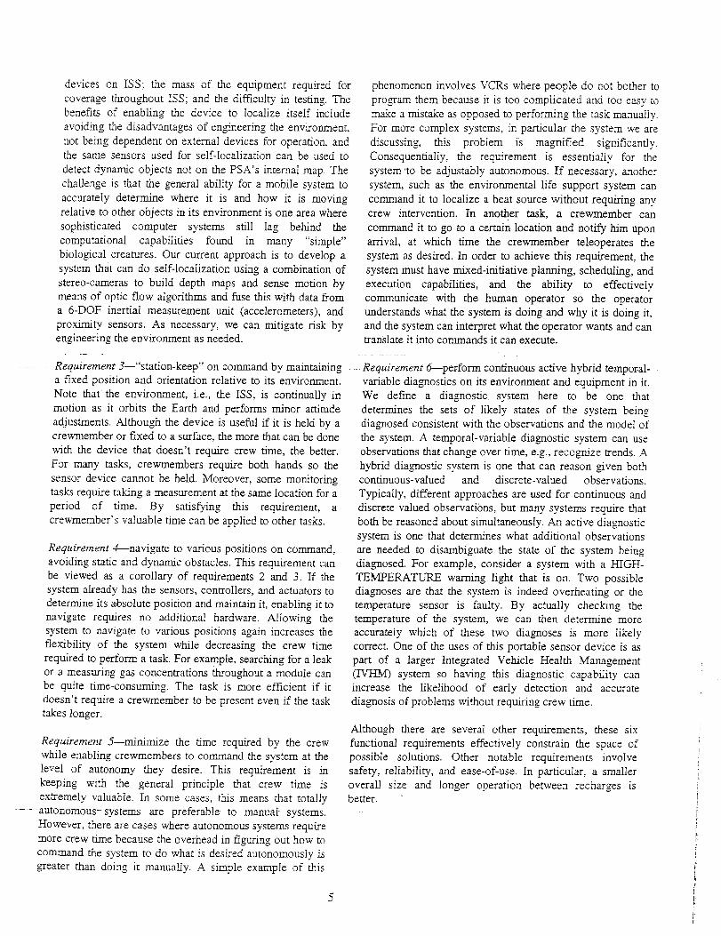
We have recently integated our PSA-specific simulator with
a general-purpose 3D simulator, which provides 3D-rendered _aphics and object dynamics. The current version
is a synthesis of the gaphics provided by the SGI OpenInventor TM obJect-oriented 3D toolMt built on top of Open
GL® and the CMLabs Vortex rigid-body physics simulator.By providing VR/vIL and collision models of the ISS, we
can navigate multiple PSA's throughout the ISS and interact
with simulated crewmembers, payloads, and objects. InFigure 6, a PSA is shown with a crewmember in the [SS
U.S. Lab "Destiny" module.
Figure 6 - 3D simulator screenshot of PSA-in ISSwith crewmember
In addition, this simulator has a scripting capability forcontrolling the environment. V_rehave added an environment
simulator to it to simulate fires, pressure leaks, and other
faults to test the diagnostic capabilities of the ?SA and its
autonomous control system. Although software simulators
can accelerate the software development process, we also
use the same autonomy software, often executing similar
scenarios, to control the physicals PSA prototypes in thephysical simulators. These scenarios, some of which are
described in the next section are helpful in testing thefidelity of the software simulators as welI as the PSAhardware and software.
6. SAMPLE MISSION TEST SCENARIOS
In order to measure the system capabilities with reference to
the operation requirements and to identify the challengingproblems, several scenarios have been developed. Thesescenarios are desig-ned to be executed both in simulation as
well as with the prototype hardware in the test facilities.
Thesescenarios perform a valuable role in measuring_our
current capability levels. They are also useful for regressiontesting. As software and hardware changes, we can run these
scenarios to demonstrate we have not Iost any capability. As
the functionality of the autonomous control system, the
prototypes, and the environment simulators increase, weraise the bar by increasing the complexity of the scenarios.
The current scenarios that the system is being designed toaddress are:
Scenario A: Robust generation of an ISS module
environment map
Description--
PSA will create an enviromment map of the !SS module bytraversing the space in a serpentine path recording theenvironment sensor readings along the way. During thisactivity, its path will be blocked by static obstacles (some ofwhich are known of ahead of time) and moving obstacles. Atone point the PSA will be interrupted to be teleoperated andthen perform a station-keeping task at a location specified byan ISS Rack Locker name, after which it will complete itsoriginal environment-mapping task.
Purpose-
. Demonstrate navigation to several waypoints in anenvironment that has static and dynamic obstacles.
• Demonstrate mixed-initiative execution includingautonomous task interruption and resumption, guardedteleoperation, and visual servoing by command.
• Demonstrate generation of a near-optimal 6-DOF routeplans
• Demonstrate obstacle detection and avoidance
• Demon_afe stereo vision-based 6-D-OF localization and
map registration
!2

ScenarioB.Participate in the diagnosis and recovery of an[SS module fizul, _
Description--
A fixed sensor in the ISS module sig-nals a high temperatureto the Environmental Control Life Support System(ECLSS). However, it is not known whether the sensor is
defective or the source or the heat. PSA is given a command
by ECLSS to go the fixed sensor location and verifv thetemperature at that location. If PSA confirms the fixed
sensor is correct, PSA is to locate the heat source and signalthe source to ECLSS, will then power down the locker atthat location. Once PSA verifies that the temperature hasreturned to normaI, it returns to its docking bay. If the fixedsensor is not correct, PSA is to stay at that location until thefixed sensor is made operational. Once PSA verifies thesensor, PSA returns to its docking bay.
Variation Summary--
1. Perfo,,'-m with faulty' fixed sensor
"_ Perform with overheating locker
Purpose--
• Demonstrate Integrated Vehicle Health Management
• Demonstrate cooperative multi-agent planning andexecution
• Demonstrate generation of a near-optimal 6-DOF routeplans
• Demonstrate stereo vision-based 6-DOF localization and
map registration
Scenario C: Fault Detection and Cooperative diagnosis ofan ISS module atmosphere leak
Descrip_ion--PSA is commanded to perform a routine task to monitor an
ISS locker. While en route, PSA detects a drop in pressure inthe module. It interrupts its current task and performs a setof directional microphone sensor readings to determine the
cause is a leak to space and then PSA isolates the generallocation of the leak. PSA reports this information to ECLSS,which then dispatches and external spacecraft mobilemonitor to the general location outside station where itimages the region of the leak to get visuaI confirmation.
Purpose--
• Demonstrate Inte_ated Vehicle Health Management
• Demonstrate dynamically changing plan to respond tofault detected in the environment
• Demonstrate multi-agent cooperative diagnosis
Scenario D: Cooperative Dam Collection and Crew
Instruction for Perfornzing Interactive Mission ScienceExperiments
Description--Crewmember commands PSA to follow him to an ISS rack
where he will perform an experiment. When he arrives, hecommands PSA to point at the locker where he will work.After positioning PSA as desired, he commands PSA to
13
maintain that position and start recording the video and
audio. He commands PSA to brief him on experiment X andto instruct him on the first step of the experiment. Once thec._vm .... b_, completes that step, he requests the ...... stepand so on until aI1 steps of the experiment are completed. Hethen commands the PSA to visually servo to face his face to
record a summary of the experiment while he is moving. Hethen instructs PSA to stop recording and return to itsdocking bay, which it does.
Purpose--
• Demonstrate automated data collection
• Demonstrate human - autonomous system collaboration
• Demonstrate autonomous teleconferencing with face-tracking
• Demonstrate person following
• Demonstrate automated task instruction
- Demonstrate spoken Ianguage commanding and reporting
Scenario E. Long-term mixed-initiative plannin.o andUff{iihiScz{i_)hinc[uding inv enio _- irac_ih g
Description--
PSA is given a list of visual servoing goals with time
constraints and is requested to generate a near-optima/ planto achieve the goals. The goals will be such that it will benecessary to schedule multiple battery recharges in order toachieve them. The operator will dynamically' change theplan prior to its execution. During the execution, PSA will
monitor the location of inventory items it senses as it passesby. PSA witI encounter static and dynamic obstacles in theenvironment. Due to an inaccurate battery" model, PSA wi]Ihave to replan to prevent running out of power prior tor_eharo, ino _t the, doc.Vdn_ h._,, Once vq a has completed thegoal list, it given a list of inventory items to locate, some ofwhich it passed by. PSA responds with the locations of theitems it senses and then generates a plan to explore the areasof the ISS module it did not previously explore in order tolocate the other items.
Purpose-
- Demonstrate near-optimal path plan generation
• Demonstrate resource planning
• Demonstrate static and dynamic obstacle avoidance
• Demonstrate mixed-initiative plan generation
• Demonstrate spoken language commanding and reporting
• Demonstrate inventory item sensing and location tracking
7. FUTURE WORK
Future research and development efforts will focus on
system-level active hybrid diagnosis, fleet operations(several _PSAs.-working__together to. handle environmental
problems) as well as autonomous operations with spacecraft
command and control systems (instead of human
commandinJteIeoperating). Long-term functional upuades
might include adding effectors, e.g., arms, capable of control
panel operation, payload maintenance, re-supply, and repair.

Oneof thefuturegoalsofthePSAR&Distodevelopkeyfunctionalcapabilitiesandprovethefeasibilitiesformicroroboticcheckoutandrepairof autonomousspacecraftandprobes.Thislong-termgoalisdrivenbytherecentfailuresin variouslow earthsatellites,deepspaceandplanetaryprobes.These faiIures are particularly troublesome because
of our inability to properly identify the contributory failure
factors and therefore leave NASA and industry at risk ofrepeating the same failures in the future.
A generic mission scenario would involve an expendable,
golf-bali sized PSA to Iaunch itself from the probe orsatellite at key points in the mission: orbit insertions,
systems checkout, major maneuvers, etc .... This ability todo a fly-by type of checkout would help insure the
spacecraft is ready for its next major event and help isolate
contributory failure factors in the event of a mishapoccurring later in the mission. The other mode of the PSA to
operate in would be post-failure.-In this role the PSA would
support-the fault detection, isolation and recovery processes.
By being able to inspect the vehicle externally manypossible failure scenarios could be evaluated and properly
closed out. For some failures special effectors on the PSA
might be able to assist in the recovery process (especiallylatch failures, or icing, or leaks where special efforts could
be designed to affect these scenarios (torches, robotics arms,sprays, etc.).
To address this future vision objective several technologieswould have to be demonstrated:
Miniaturization of the PSA down to a golf-ball sizedspacecra_--this design goal would enable the PSA to be
carried on smalI satellites and probes without incurring a
sig-niflcant volume and weight penalty. The size, andthereby hopefully cost. would allow several PSA's to be
carried as expendable devices to maximize coverage andminimize collision potential
Highly developed vision and remote sensing capabilities--
these technologies would enable the PSA to navigate arounddelicate and complex subsystems such as antenna's, powerarrays, external sensors, latch and other activation
mechanisms, and other structural components. The ability todo close inspections would be key to the fault detection and
isolation requirements as welI as supporting some of the
recovery efforts. Non-destructive inspections such asthermal or others would also significantly support the fault
detection and isolation goals.
Precise robotic effectors--these technologies, some of
which aIrecrdy exist-, wo_ald enable the-PSA-not on/y to
conduct inspections, but also, in limited form support
recover), operations. These include anything from sprayingsealants to freeing latches, or re-pointing instruments to re-
heating equipment.
Advanced imefiigence systems--this technology would be
required to enable the PSA to efficient!y help diagnosis a
system faiiure. The drivers for this capabiiity are as follows:
remote operations - which cause time delays that would
make manual operations infeasible; complex environments -
the structural architectures of the satellites or probes wouldrequire very precise and efficient operations that would
make human operations, if feasible, very taxing, and highrisk; efficient fault detection and isolation - PSA's that
could do mishap investigation and analysis autonomously
would enable optimized inspections potentially savingprecious resources instead of having to wait on remotehuman collaborations.
,amother useful spacecraft mobile robot is a multi-armed
"monkey-sized" PSA is to perform various tasks from the
mundane, e.g., changing filters, to the critical, e.g., repairinga leak. Consider a future mission where a spacecraft is sentto Mars and remains in orbit unoccupied while the crew is
stationed on the Martian surface. This large PSA could beused to monitor and maintain the flight worthiness of thespacecraft and reduce mission risk.
One of the challenges of this project is balancing on the
edge of the possible. If we were to incorporate all thefascinating ideas from the PSA team and others interested in
the project, it would most likely be so technically
impractical we would not end up deploying anything.However, if we were to descope them all, we would
probably end up with something so unhelpful and difficult to
use it wouId not be worth doing at aI1. By having these long
term visions in mind now, the PSA team and supportingresearch organizations can optimize both investments and
technology requirements to help meet both short term andlong term requirements.
8. RELATED WORK
At this time, no free-flying vehicles have been deployed for
performing operations inside spacecraft in flight. However,this work stands on the shoulders of a large body of work onsatellite development and control. A similar vehicle, the
Sprint AERCam, designed to be teleoperated outside of
spacecraft, was successfully flight-tested outside the STS87
space shuttle flight in 1997 [6]. Sprint was a free-flyingspherical robot that weighed about 351bs and was 14" in
diameter. It had no localization and proximity sensingcapabilities. It had 12 nitrogen-gas thrusters for propulsion
and attitude control. Its primary mission sensors were two
color video cameras for supporting teleoperation, forproviding video support for crew ex_'a-vehicular activities
- (-E-VAs'Ir or- performing recomnaissanee in- iieu of an-EVA.
An effort to create a mini AERCam is ongoing at JSC [7J.
Work on cooperative astronaut/mobile-robot operations isbeing done with the SC,*MMP SSV, an underwater vehicle
designed to simulate a spacecraft [8]. The Synchronized
Position Hold, Engage Reorient, Experimental Satellites
14

(SPHERES) project at the M[T Space Systems Laboratory,
consists of three 8"" spherical spacecraft for testing tbrmation
flying of spacecraft and multi-agent control algorithms [9],
[i0]. The vehic!es use CO, thrusters for propulsion and
attitude control. SPHERES is scheduled for an ISS flightexperiment in 2003. Four external-fixed 1-_'Ultrasound
beacons are used by the SPHERES for Iocalization in theirworkspace. -6'x6'x6". Onboard sensors are limited to IR
and ultrasound receivers for beacon detection.
9. SL_IMARY
We presented the ongoing research and development effortto design an internal spacecraft autonomous mobile monitorand the accompanying autonomous control software that is
applicable to a wide range of free-flying vehicles. Therationale for the effort was presented as well as anillustrative scenario that shows how a PSA might be usedonce deployed. We discussed the high-level functionalrequirements of the project followed by a description of fivePq& nrntntvn,,:.< nf inor,_n_'_ner eramnlo'v;tx,-_._A G,4_I;*_, _f
- which twn-hnvo h,--_n dopln,,_,_ _nA th,= eh;,-A ;e ho;_,-,
designed. We also briefly, discussed the micro-gavity testfacility, which allows us to fly the PSA prototypes on the_ound as if they were onboard the ISS. The autonomyframework for intelligent flight vehicle control beingdeveloped and tested as part of this project was alsopresented. Several sample missions being used to test theproto.types and the autonomous control system were alsooutlined. We concluded with a discussion of both the short-term and long-term future work in the area of autonomous
mobile vehicles for in-flight spacecraft support.
ACKNOWLEDGMENTS
The work presented is the paper is the result of _e
extraordinary efforts of many talented people far too
numerous to individually identify. Rather than erring by not
specifically acknowledging anyone, we ask to be pardonedby those we have omitted and gratefully acknowledge thecontributions of Rick Alena, Daniel Andrews, Kevin Bass,
Michael Belgarde, Jeff Bradshaw, Jeff Brown, Phil Canias,Ling-Jen Chiang, Howie Choset, SaI Desiano, John
Dowding, Vineet Gupta, Peter Hamlett, Jim Hanratty, JamesHieronymous, Denver Hinds, Beth Ann Hockey, LynnHofland, David Husmann, Frankie James, Paul Keas, Linda
Kobayashi, Kurt Konolige, David Kortenkamp, Brian Koss,
John Loch, Nghia Mai, John Marmie, Mike McIntyre,Sergio Mendoza, Nicola Muscettola, Charles Neveu, Keith
Nicewarner, Ana Papasin, Richard Papasin, Eric Poblenz,
beIanny Rayner, Mark Shirley, Mark Sibenac, Doug Smith,Adam Sweet, Hans Thomas, Vinh To, Mark Turner, Kristen
Vollrath, Brian Williams, and Serge Yentus. In addition, we
acknowledge the financial and manaeement sulzportp_Vi_a--gy rife N,_,K-Cross-Ente_se 2_ecl{n_iog,,v
Development Program, the Computing, Information, and
Technology Pro_am, and the Engineering ComplexSystems Program.
REFERENCES
r_ _ Gre;orv A. Dorais, et al., ",am, autonomous control system
for an intra-vehicutar spacecraft mobile mepdtor protovjpe."Proceedings of the 7_ Intemationai Symposium on Artificial
[ntelIigence, Robotics, and Automation in Space (i-S._JL4S),Nara, Japan, May 19-23. 2003. To be published.
[2] Douglas Bernard, et aI., "Final report on the Remote Agent
experiment." In Proceedings of the New Millennium ProgramDS-1 Technology Validation Symposium, Pasadena, CA,Februa® 8-9, 2000.
[3] Ari K. Jonsson, et al., "Planning in interplanetary space:theory and practice." Proceedings of the yh Arzificial
Inte!ligence Planning and Schedulino Conference,Brekenridge, CO, 2000.
[a] Nicola Muscettola et el., "A unified approach to model-based p!anning and execution." Proceedings of dw Sixthlnte_r.na(iod_al Conferen_ce on Intelligent AutonomousSystems, Venice, Italy, 2000.
[5] Manny Rayner, Beth Ann Hockey. and Frankie James, "A
compact architecture for dialogue management based on
scripts and meta-outputs." Proceedings of Applied NaturalLanguage Processing (ANLP), 2000.
[6] "NASA AerCam Sprint" Project website.
http://tornmy.jsc.nasa.gov/projectsISprint, April 28, 1998.
[7] Steven Fredrickson, "blini AerCam." Video Presentation
ar NASA's Johnson Space Center, October I1 2001.
http://explorer.arc, nasa.gov: 8080/ramgerv'Archive/Robotics/vits.rm.
[SJ Ella M. Atkins, Jamie A. Lennon, and Rhiannon S. Peasco,
"Vision-based following for cooperative astronaut-robot
operations." Proceedings of dze IEEE Aerospace Cotg'erence.Big Sk7 NIT, March. 2002.
[9] David Miller et aI, "SPHERES: a testbed for long durationsatellite formation flying in micro-_avity conditions."
Proceedings of dze 2000 _4SZ4IAA Space Flight Mechanics
Meerin S, AAS 00-110, American Astronautical Society,Clearwater, Florida, 1/23-26/2000.
http://ssl.mit.edu/spheres/Docs/A_4S-AIAA.pdf.
(10] Steve Sell, "SPHERES: Synchronized Position Hold.
Engage. Reorient, Experimental Satellites." Slide Presentation
at the Jet Propulsion Laborato_ Cenrer j'br Integrated SpaceMicro©stems, Pasadena, CA, April 2, 2002.
http://cism jp!.nasa.gov/e_ vents/wor_hop/SPD_RES.pdf.
15
GregoryA. Doraisis a Co-PrincipleInvestigator of the PSA and is its project
manager as well as its autonomy lead in
the Autonomy and Robotics Area at theNASA Ames Research Center. He was a
member of the Remote Agent Executive
development team and was the Remote
Agent System Inte_ator for the Deep
Space One spacecraft. He also was a co-developer of the IDEA autonomous
control system based on the Remote Agent. He was a
member of the Design tbr Safety Pro_am Planning team
where he led the Resilient Systems and Operation project.He was also a co-Principle Investigator on a Human-
Centered Autonomy project. He has performed autonomous
rover research at JPL and remote sensing research at
General Motors Research. At the University of Michigan, he
performed autonomy research, was a member of the rover
development team, and developed an automated system forinferring classification and forecasting models from data. He
recei,zed his Ph.D. from the University of Michigan in
Computer Science with a concentration in IntelligentSystems. His research interests include autonomous systems,
robotics, machine vision, and machine learning.
Yuri Gawdiak is a Co-PrincipleInvestigator of the PSA and originated
its conceptual design. He is currently the
program manager for the EnNneering _2@_,Complex Systems progam. He has had
many roles in the development of the
ISS, including Network Engineer andTechnical Management Information )
System manager at NASA headquarters.
He was also on the Space Station
Redesign Team B at NASA Langley Research Center as aPayload Avionics Design Architect and inteuated portable
computers into the ISS baseline desi_o-n. At NASA Johnson
Space Center, he worked on the development of payload
avionics and developed the Wireless Network experimentfor the ISS. At NASA Ames Research Center, he was the PI
for the Wireless Network Experiment on STS-76/Mir 21 andperformed research that led to a wireless LAN baseIine
augmentation on the ISS. He also held management roles in
the Aviation Safety Program and led the development of theSurface Movement Advisor system for airport _ound traffic
management in the Airspace Systems Pro_am. Prior to his
work at NASA, he was a Systems Analyst for the DefenseCommu_cation Agency working on the World-wide
Military Command and Control system and the Human-
Computer Interface lab manager at University of Maryland.
He has a B.S from Carnegie Mellon University in
Information Systems with a concentration in Ergonomics.
16