THE PENNSYLVANIA STATE UNIVERSITY SCHREYER HONORS...
80
-
Upload
nguyendung -
Category
Documents
-
view
218 -
download
2
Transcript of THE PENNSYLVANIA STATE UNIVERSITY SCHREYER HONORS...


THE PENNSYLVANIA STATE UNIVERSITY
SCHREYER HONORS COLLEGE
DEPARTMENT OF MECHANICAL AND NUCLEAR ENGINEERING
DEVELOPMENT OF AN OFF-ROAD GROUND VEHICLE PLATFORM FOR
TELEOPERATION
STEPHEN M. CHAVES
Summer 2008
A thesis
submitted in partial fulfillment
of the requirements
for a baccalaureate degree
in Mechanical Engineering
with honors in Mechanical Engineering
Reviewed and approved* by the following:
Sean N. Brennan
Assistant Professor of Mechanical Engineering
Thesis Supervisor
Matthew M. Mench
Associate Professor of Mechanical Engineering
Honors Adviser
*Signatures are on file in the Schreyer Honors College.

We approve the thesis of Stephen M. Chaves:
Date of Signature
______________________________________ ____________
Sean N. Brennan
Assistant Professor of Mechanical Engineering
Thesis Supervisor
______________________________________ ____________
Matthew M. Mench
Associate Professor of Mechanical Engineering
Honors Adviser
9-5506-3767

iii
ABSTRACT
This thesis deals with the teleoperation of a ground vehicle, specifically the construction
processes associated with actuating the vehicle and the computer systems necessary for
its control. The primary objectives of this thesis are to present the successes and failures
of developing a ground vehicle platform to be used for teleoperation, to outline the
computer architecture needed for wireless control of the vehicle, and to convey the
lessons that were learned along the way.
Development of a teleoperated vehicle is a multi-faceted project. One of the most
important steps to a successful teleoperated vehicle is the construction of a capable
actuation system. Once the actuation system is designed and constructed, the system
must be given commands to govern its performance, and hence the performance of the
teleoperated vehicle. With the development of an off-road vehicle platform, the
groundwork is laid for significant advances in teleoperation and the entire field of
unmanned vehicle technology.

iv
for my parents

v
TABLE OF CONTENTS
ABSTRACT ....................................................................................................................... iii
TABLE OF CONTENTS .................................................................................................... v
LIST OF FIGURES ........................................................................................................... vi
ACKNOWLEDGMENTS ............................................................................................... viii
Chapter 1 Introduction ....................................................................................................... 1
1.1 Background on Teleoperation .............................................................................. 2
1.2 Motivation for Research from the Automotive Industry ...................................... 3
1.3 Motivation for Research from the Aerospace and Defense Industries ................. 4
1.4 Outlook and Objectives ........................................................................................ 5
Chapter 2 History of Teleoperated and Autonomous Ground Vehicles .......................... 10
Chapter 3 Actuation of the Vehicle.................................................................................. 20
3.1 Overview of the Go-Kart .................................................................................... 20
3.2 Steering the Go-Kart........................................................................................... 22
3.3 Throttle and Brake Actuation ............................................................................. 35
Chapter 4 Radio Control of the Vehicle........................................................................... 41
4.1 Overview of the Radio Control System.............................................................. 41
4.2 Improvement Identification and Design Revision .............................................. 44
Chapter 5 Computer Control of the Vehicle .................................................................... 49
5.1 Overview of the Computer Control System ....................................................... 49
5.2 Testing of the Computer Control System ........................................................... 56
5.3 Identification of Areas for Improvement ............................................................ 60
Chapter 6 Conclusion ....................................................................................................... 62
6.1 Future Work........................................................................................................ 63
REFERENCES ................................................................................................................. 64
APPENDIX ....................................................................................................................... 66
Products Purchased........................................................................................................ 66
Snapshots of the Vehicle in Action ............................................................................... 68

vi
LIST OF FIGURES
Figure 1.1: The Immersive Driving Simulator at PTI (Courtesy of PTI)…………………8
Figure 2.1: The Tsukuba Intelligent Vehicle (Courtesy of Advanced Cruise-Assist
Highway System Research Association) .......................................................................... 12
Figure 2.2: The NOSC ATT Dune Buggy (left) and TOV (right) (Courtesy of the Space
and Naval Warfare Systems Command) ........................................................................... 13
Figure 2.3: Ernst Dickmanns and the VaMoRs and VaMP (Courtesy of the University of
Bundeswehr, Munich) ....................................................................................................... 14
Figure 2.4: The Navlab 5 (Courtesy of Carnegie Mellon University) .............................. 16
Figure 2.5: The ARGO Autonomous Vehicle (Courtesy of the University of Parma) ..... 17
Figure 2.6: Stanley (Courtesy of Stanford University) and Boss (Courtesy of Tartan
Racing) .............................................................................................................................. 18
Figure 3.1: The Off-road Go-Kart Used as the Ground Vehicle Platform for
Teleoperation .................................................................................................................... 21
Figure 3.2: View of the Steering Column ......................................................................... 23
Figure 3.3: View of the Steering Arm............................................................................... 23
Figure 3.4: Tonegawa Seiko SSPS105 (Courtesy of Tonegawa Seiko) ........................... 25
Figure 3.5: R+W America SK1 Mechanical Torque Limiter (Courtesy of R+W America)
........................................................................................................................................... 28
Figure 3.6: SolidWorks Model of Initial Steering Connection ......................................... 29
Figure 3.7: Initial Steering Connection ............................................................................. 30
Figure 3.8: Isometric SolidWorks View of the Servo Mounting Frame........................... 33
Figure 3.9: Right Side SolidWorks View of the Servo Mounting Frame ......................... 33
Figure 3.10: The 80/20 Steering Frame ............................................................................ 34
Figure 3.11: Brake and Throttle Pedals (respectively) ..................................................... 36
Figure 3.12: SolidWorks Model of Linear Actuators ....................................................... 39
vii
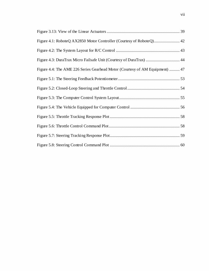
Figure 3.13: View of the Linear Actuators ....................................................................... 39
Figure 4.1: RoboteQ AX2850 Motor Controller (Courtesy of RoboteQ)......................... 42
Figure 4.2: The System Layout for R/C Control .............................................................. 43
Figure 4.3: DuraTrax Micro Failsafe Unit (Courtesy of DuraTrax) ................................. 44
Figure 4.4: The AME 226 Series Gearhead Motor (Courtesy of AM Equipment) .......... 47
Figure 5.1: The Steering Feedback Potentiometer ............................................................ 53
Figure 5.2: Closed-Loop Steering and Throttle Control ................................................... 54
Figure 5.3: The Computer Control System Layout........................................................... 55
Figure 5.4: The Vehicle Equipped for Computer Control ................................................ 56
Figure 5.5: Throttle Tracking Response Plot .................................................................... 58
Figure 5.6: Throttle Control Command Plot ..................................................................... 58
Figure 5.7: Steering Tracking Response Plot.................................................................... 59
Figure 5.8: Steering Control Command Plot .................................................................... 60

viii
ACKNOWLEDGMENTS
I would first like to thank Dr. Sean Brennan for his supervision throughout this thesis and
his dedication to helping me excel. He has been a great mentor and a large part of my
development as a successful student.
Most importantly, I would like to thank my parents. You have always believed in me and
demanded my best. Thanks for loving me so well. Mom and Dad, I love you.
1
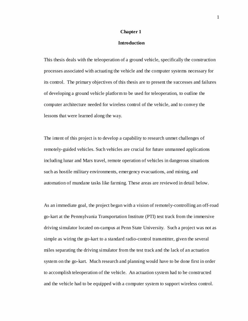
Chapter 1
Introduction
This thesis deals with the teleoperation of a ground vehicle, specifically the construction
processes associated with actuating the vehicle and the computer systems necessary for
its control. The primary objectives of this thesis are to present the successes and failures
of developing a ground vehicle platform to be used for teleoperation, to outline the
computer architecture needed for wireless control of the vehicle, and to convey the
lessons that were learned along the way.
The intent of this project is to develop a capability to research unmet challenges of
remotely-guided vehicles. Such vehicles are crucial for future unmanned applications
including lunar and Mars travel, remote operation of vehicles in dangerous situations
such as hostile military environments, emergency evacuations, and mining, and
automation of mundane tasks like farming. These areas are reviewed in detail below.
As an immediate goal, the project began with a vision of remotely-controlling an off-road
go-kart at the Pennsylvania Transportation Institute (PTI) test track from the immersive
driving simulator located on-campus at Penn State University. Such a project was not as
simple as wiring the go-kart to a standard radio-control transmitter, given the several
miles separating the driving simulator from the test track and the lack of an actuation
system on the go-kart. Much research and planning would have to be done first in order
to accomplish teleoperation of the vehicle. An actuation system had to be constructed
and the vehicle had to be equipped with a computer system to support wireless control.

2
1.1 Background on Teleoperation
Fong and Thorpe define teleoperation as simply “operating a vehicle at a distance.” They
allow the term “teleoperation” to include some form of vehicle autonomy, where the
operator mainly supervises the vehicle in action rather than controlling it, although other
authors disagree on this definition. Teleoperation is often used for vehicle control in
hard-to-reach environments or to minimize mission expenses, and frequently in situations
that are deemed too dangerous for human presence. Fong and Thorpe also identify
characteristics of vehicle teleoperation that are crucial to its success, namely reliable
navigation, capable motion command generation, and localized sensor data (Fong and
Thorpe).
Teleoperated vehicles are just one category of “unmanned ground vehicles,” or UGVs. A
second category of UGVs are autonomous vehicles, defined by Gage as vehicles that
“determine their own course using onboard sensor and processing resources.” Gage
differs from Fong and Thorpe in his definition of teleoperated vehicles, reserving the
term for vehicles solely controlled from an external operator with no form of autonomy
involved. He uses the term “supervisory control” for any sort of vehicle that combines
commands from external operators and onboard sensors to navigate (Gage). Regardless
of the definitions however, both teleoperated vehicles and autonomous vehicles share
many technological characteristics, including similarities in vehicle actuation and
computer architecture. Motivation for increased research within the two categories
remains very similar as well. There are a wide range of interests for advancing UGV

3
technology, particularly from the automotive industry and aerospace and defense
industries.
1.2 Motivation for Research from the Automotive Industry
According to the U.S Department of Transportation, over 6,000,000 highway vehicle
accidents were reported in the United States each year between 1990 and 2005
(Transportation Accidents by Mode). On average, over 40,000 fatalities were reported
for each of these years due to highway accidents, with the number of injured passengers
even higher (Transportation Fatalities by Mode). With such staggering statistics, it is
easy to see why the government and automotive industry are interested in researching
intelligent vehicles.
A major goal of the Department of Transportation’s Automated Highway System
program is to implement partially-automated, and eventually fully-automated, vehicle
control technologies to improve the safety and efficiency of U.S highways (Gage).
Intelligent transportation systems (ITS) are also being researched for economical and
environmental reasons, notably to reduce energy consumption, and even to improve upon
automobile comfort and convenience (Schmidt) (Bertozzi, Broggi and Cellario). The ITS
approach is an integrated approach that links vehicles, drivers, and embedded electronic
and computer systems and can be considered a subset of UGV and autonomous vehicle
research (Bertozzi, Broggi and Cellario).

4
Reduced congestion, better fuel economy, and increased awareness of other vehicles and
the surrounding environment are all objectives of the ITS initiative that will be addressed
as UGV technology improves. Passenger vehicles may not qualify as “unmanned ground
vehicles,” but the advancements in UGV technology can be implemented within the
automotive industry as within the aerospace and defense industries. However, the
aerospace and defense industries have slightly different intelligent vehicle applications in
mind, whether partially or fully autonomous.
1.3 Motivation for Research from the Aerospace and Defense Industries
Within the aerospace and defense industries, human involvement in hazardous or life-
threatening situations on land is quickly being replaced by UGVs (Pezeshkian, Nguyen
and Burmeister). These situations typically call for some form of reconnaissance or
surveillance, although UGVs are beginning to see action in military combat situations as
well. The urgency to implement UGVs for military applications increases with each
soldier casualty. The U.S. Department of Defense has demanded UGV research ever
since the release of a congressional mandate stating that one-third of military ground
vehicles must be unmanned by 2015 (McWilliams, Brown and Lamm).
Aerospace and defense industry examples of UGVs include military robots used for
explosive ordnance disposal (EOD), teleoperated dune buggies for Reconnaissance,
Surveillance, and Target Acquisition (RSTA), and a range of NASA exploration rovers
(Gage) (McWilliams, Brown and Lamm). Space exploration rovers have been in
existence for decades, as rovers drastically reduce the cost of spaceflight missions,

5
eliminating the need for manned spacecraft and complex, costly life-support systems
(Gage). Thus, space exploration continues to be an area of motivation for unmanned
ground vehicles.
Aside from military vehicles and exploration rovers, Fong and Thorpe identify a third
classification of UGVs known as hazardous duty vehicles. Not unlike military and space
vehicles, hazardous duty vehicles are employed in situations that pose extreme danger to
humans, often related to chemical or toxic waste removal (Fong and Thorpe), mining
operations, or bomb disposal.
No matter the application, one common theme is present throughout the industries:
reduce human involvement. Reduction in human involvement means the reduction of
potentially dangerous situations and improvement in safety and comfort. As a result,
operational efficiency and capability increase, and mission expenses and human fatalities
decrease.
1.4 Outlook and Objectives
Nielsen, Goodrich, and Ricks suggest that perhaps the greatest reason for poor navigation
of teleoperated vehicles to date has been the lack of situational awareness, or
“telepresence,” for the operator (Nielsen, Goodrich and Ricks). Earlier it was stated that
the third crucial characteristic for teleoperation is localized sensor data, due to the
necessity to convey the vehicle’s surroundings to the operator. Based on past experiences
however, Nielsen, Goodrich, and Ricks present that operators usually have less than

6
adequate knowledge of the vehicle’s environment. It is often difficult for operators to
fully extract an understanding of the environment from the video images that so many
robots transmit (Nielsen, Goodrich and Ricks). Video data is an integral component of
direct interfaces, the most common type of teleoperation interface, despite their tendency
to be problematic. Direct interfaces typically feature an operator watching video from the
robot while giving commands with hand-held controllers. Loss of situational awareness,
inaccurate attitude judgment, and poor obstacle detection are all common faults with
direct interfaces (Fong and Thorpe). As a result, operators turn to navigating the vehicle
at very low speeds, which can be a tiresome process that demands extreme caution
(Babic, Budisic and Petrovic).
There have been recommendations for improving this issue with teleoperated vehicles,
including increased use of maps, better sensor fusion, and providing operators with more
spatial information (Nielsen, Goodrich and Ricks). The implementation of a more
sophisticated interface with higher data quality has been suggested by numerous
researchers (Babic, Budisic and Petrovic). Specifically, this thesis focuses on laying the
groundwork for these types of improvements. By developing a vehicle and interface
where telepresence of the operator can be dramatically improved, successfully
teleoperation is much more probabilistic.
Fong and Thorpe state that the use of direct interfaces works best when real-time control
of the vehicle is needed and a high-bandwidth, low-delay communication route is
accessible (Fong and Thorpe). However, this often means that teleoperation over a long

7
distance is very difficult, as data transfer becomes less reliable. Bandwidth limitations
are limitations that cannot be altered and must be factored into the design of the system
(Grange, Fong and Baur). In 2001, a publication entitled “UGV Lessons Learned”
identified “communications are not dependable” as one of the top ten lessons learned.
The authors urged researchers to develop systems that reduced communication
requirements and emphasized vehicles thinking for themselves (Blackburn, Laird and
Everett). Overreliance on communications is a key pitfall for successful teleoperation.
Thus, it follows that an optimal teleoperation system conveys high-quality environmental
data to the operator while limiting information transmission. The goal of this thesis is to
develop a platform where such a system is achievable. While data fidelity is limited by
communication bandwidth restrictions, it can be improved by increasing the fidelity of a
virtual environment in which an operator controls the vehicle. Rather than continuously
transmitting video images from robot to operator, navigating the robot in a structured,
known environment reduces the dependency on large data transmission. Knowledge of
its surroundings can be embedded in the vehicle’s computer architecture, as well as the
operator’s interface. The operator, if equipped with adequate spatial information and
terrain characteristics, can navigate without hesitation or lack of confidence in the
information conveyed in video images. Some level of local autonomy would
undoubtedly be involved, as the robot could react to discrepancies between the
environment it “sees” and the environment it expects to see. Even by only conveying
these discrepancies to the operator, the total amount of data transmitted is significantly

8
reduced. As a result, a high-fidelity system is attainable that increases the situational
awareness of the operator and depends little on data communication.
Ultimately, the objective of this work is to control the ground vehicle developed
throughout this project via the immersive driving simulator located at PTI on-campus at
Penn State University (see Figure 1.1). The vehicle itself will be navigating a known
environment several miles away at the PTI test track. Both the vehicle and simulator will
consult a LIDAR map of the region to successfully drive at high speeds without
hesitation or collision. Preliminary developments of the vehicle and computer
architecture needed for its control are presented in this thesis.
Figure 1.1: The Immersive Driving Simulator at PTI (Courtesy of PTI)
The outline of the thesis is as follows: chapter two presents a brief history of intelligent
vehicle research to this point, chapter three discusses the actuation of the ground vehicle
and its construction, chapter four presents the radio control phase of the vehicle’s
development, and chapter five outlines the implementation of computer systems onto the

9
vehicle. The outcomes of the thesis are summarized in the conclusion section, and future
work is listed for later reference.

10
Chapter 2
History of Teleoperated and Autonomous Ground Vehicles
It is appropriate for this thesis to present a brief history of teleoperated and autonomous
ground vehicles. Examining UGV research of the past helps to understand the state of
current research and gives a clearer picture of the motivation for continuing to advance
the field. Presented in this section are some examples of development efforts that were
regarded as state-of-the-art during their respective time periods.
Many consider the earliest demonstration of mobile robots to be the wheeled platform
named SHAKEY, researched at the Stanford Research Institute and funded by DARPA in
the 1960’s (Gage). SHAKEY was the first development effort to show some form of
path planning and automated navigation, using its onboard TV camera and ultrasonic
range finder to explore (Meyrowitz, Blidberg and Michelson). Stanford University
continued in the 1970’s to be a leader in robot mobility, with the work of Hans Moravec
and his Stanford Cart. The Cart moved through cluttered environments at a very slow
speed (one meter every 15 minutes), using a TV camera vision system (Gage).
In 1981, Moravec moved to Carnegie Mellon University and developed the CMU Rover,
a more capable robot able to handle more complex perception and control experiments
(Meyrowitz, Blidberg and Michelson). Moravec’s robot work paved the way for
significant intelligent vehicle advancements at Carnegie Mellon University, highlighted
by the Navlab projects in the 1990’s, presented later in this section.

11
Space exploration rovers are perfect examples of teleoperated ground vehicles that were
advanced for their time. As early as the 1970’s, Soviet moon rovers roamed the lunar
surface collecting samples and performing other scientific tasks, all under the command
of external operators (Fong and Thorpe). Since these first vehicles, NASA has developed
their own teleoperated rovers, including the Dante, Nomad, Sojourner, and recent Mars
rovers that have long exceeded their life expectancy.
It can be argued that the beginning of full-size autonomous vehicles can be dated back to
the 1960’s and 70’s when The Ohio State University began studies on vehicle guidance
and control as part of the Automated Highway System (AHS) research efforts. For the
first time, researchers demonstrated fully automated driving at highway speeds (30 m/s)
with wire-guided steering and longitudinal and car-following control algorithms (Fenton
and Mayhan). Automated merging and lane change maneuvers were also demonstrated.
However, researchers conceded that the development of automated highway operations
would have to wait for significant advances in sensor technology and communications.
By 1977, the Tsukuba Mechanical Engineering Lab in Japan developed what they
considered the “first intelligent vehicle.” This vehicle (see Figure 2.1) was capable of
tracking the white lane markers on the road using machine vision technology
(Association). The vehicle followed these markers for 50 meters at speeds of up to 30
km/h (Schmidhuber).

12
Figure 2.1: The Tsukuba Intelligent Vehicle (Courtesy of Advanced Cruise-Assist
Highway System Research Association)
A huge success for military teleoperation came in the 1980’s with an effort from the
Naval Oceans Systems Center (NOSC) that focused on reconnaissance, surveillance, and
target acquisition (RSTA). The Advanced Teleoperator Technology (ATT) TeleOperated
Dune Buggy was developed at NSOC Hawaii, featuring a Chenowth dune buggy
equipped with a vision system and mounted weapons. This project draws many parallels
to the work of this thesis, as the dune buggy demonstrated the ability to cross natural
terrain at high speeds while being controlled remotely (Gage). The success of the ATT
dune buggy led the NOSC to continue work on unmanned ground vehicles, producing the
new TeleOperated Vehicle (TOV) that was tested in 1988. The TOV was a HMMWV
used for long-range RSTA (up to 30 kilometers away) that required a complex control
system to integrate its sensors and actuation system (Gage). The ATT dune buggy and
TOV are pictured in Figure 2.2. Numerous other military vehicles followed these initial

13
two, demonstrating waypoint-based navigation and navigation by TV images sent to
remote operators.
Figure 2.2: The NOSC ATT Dune Buggy (left) and TOV (right) (Courtesy of the Space
and Naval Warfare Systems Command)
In 1987, the European Commission funded the EUREKA PROMETHEUS (PROgraM
for a European Traffic with Highest Efficiency and Unprecedented Safety) project. More
than one billion dollars was invested into driverless car technology up through 1995,
making the PROMETHEUS project still the largest driverless car research and
development effort ever. More than 13 vehicle manufacturers participated in the project,
as well as many government and academic research groups (Bertozzi, Broggi and
Cellario). The research group of Ernst D. Dickmanns at the University of Bundeswehr in
Munich (UniBwM) made significant contributions to the project and became the leader in
intelligent vehicle technology at that time.
Dickmanns is considered by many to be a pioneer in driverless vehicles, and more
specifically, dynamic vision as it relates to driverless vehicles. His research group at
14
UniBwM is credited with developing the world’s first autonomous vehicles, vehicles that
used saccadic vision, Kalman filtering, and parallel computers (“transputers”) to navigate
on their own (Schmidhuber).
Figure 2.3: Ernst Dickmanns and the VaMoRs and VaMP (Courtesy of the University of
Bundeswehr, Munich)
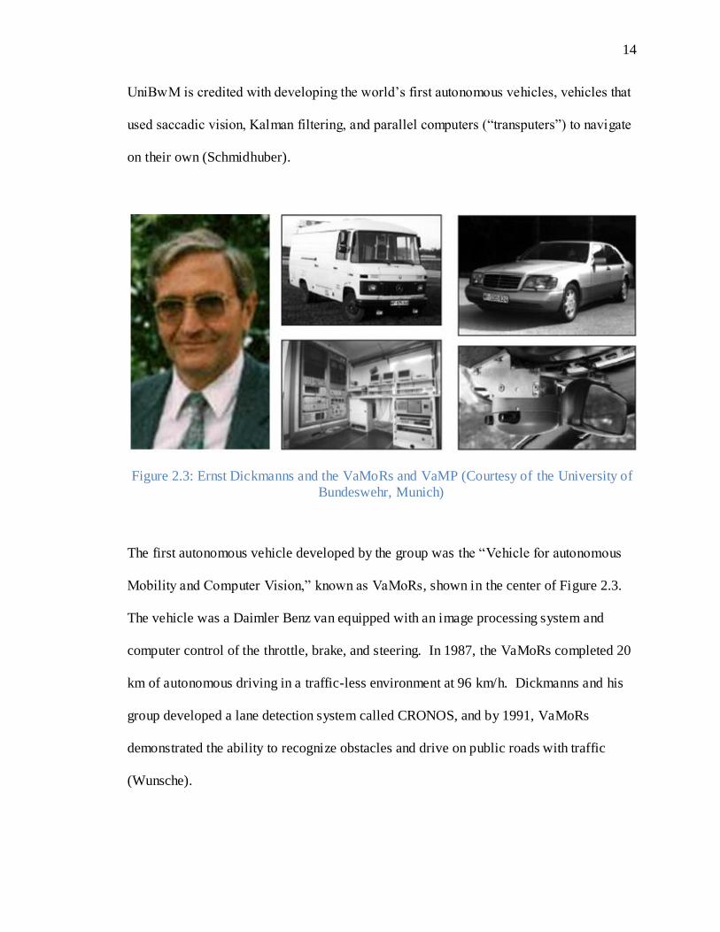
The first autonomous vehicle developed by the group was the “Vehicle for autonomous
Mobility and Computer Vision,” known as VaMoRs, shown in the center of Figure 2.3.
The vehicle was a Daimler Benz van equipped with an image processing system and
computer control of the throttle, brake, and steering. In 1987, the VaMoRs completed 20
km of autonomous driving in a traffic-less environment at 96 km/h. Dickmanns and his
group developed a lane detection system called CRONOS, and by 1991, VaMoRs
demonstrated the ability to recognize obstacles and drive on public roads with traffic
(Wunsche).

15
The VaMoRs – Passenger Car, also known as VaMP, is shown on the right of Figure 2.3.
This vehicle was Dickmanns’s second highly-significant intelligent vehicle. The VaMP
was a Mercedes Benz 500 SEL that used four cameras to navigate with vision-based
control. The system was capable of detecting up to 12 other objects, usually other
vehicles, at any given time. In 1994, the VaMP exhibited autonomous three-lane
highway driving on Autoroute A1 in Paris, keeping lanes and safe following distances at
speeds up to 130 km/h. By 1995, VaMP completed a 1758 kilometer trip that was 95
percent autonomous. The trip included over 400 autonomous lane change maneuvers and
speeds up to 180 km/h (Wunsche).
The same year (1995) that VaMP drove over 1500 kilometers on Paris highways, Dean
Pomerleau and Todd Jochem of the Robotics Institute at Carnegie Mellon University
completed their “No Hands Across America” trip. The two researchers drove from
Pittsburgh to San Diego in Navlab 5, a 1990 Pontiac Trans Sport capable of steering
itself, shown in Figure 2.4. Navlab 5 autonomously performed 98.2 percent of the
steering required for the cross-country journey, but the throttle and brake were human
controlled (Pomerleau and Jochem, No Hands Across America). Pomerleau and his
research group developed the RALPH (Rapidly Adapting Lateral Position Handler)
computer program to steer the vehicle, a program that inferred road location from video
images (Pomerleau, RALPH: Rapidly Adapting Lateral Postion Handler). They also
introduced a portable navigation platform known as PANS (Portable Advanced
Navigation Support) that provided a computing base and sensor integration station for
their vehicle. The platform was designed to be portable and transferrable, powered from

16
the vehicle’s cigarette lighter (Jochem, Pomerleau and Kumar). With the PANS,
Pomerleau proved that an inexpensive, convenient, and portable robust computer system
could be developed for intelligent vehicles.
Figure 2.4: The Navlab 5 (Courtesy of Carnegie Mellon University)
Developers from the University of Parma in Italy spent six days on a trip in 1998 testing
their ARGO autonomous vehicle, a Lancia Thema equipped with a s tereoscopic vision
system. Two cameras mounted in the front of the vehicle processed gray images to
extract road geometry and parameters of the surrounding environment, including other
vehicles (Bertozzi, Broggi and Fascioli, The ARGO Autonomous Vehicle). The ARGO
drove autonomously 94 percent of the time on the 2000 kilometer trip at an average speed
of 90 km/h (McWilliams, Brown and Lamm). An outline of the autonomous journey and
snapshot of the ARGO in action are shown in Figure 2.5. The ARGO had three different
driving modes: manual, supervised, and automated. In both the manual and supervised
mode, the vehicle assisted the human driver by warning of dangerous situations and even
assuming control of the vehicle in the supervised driving mode (Bertozzi, Broggi and
Fascioli, The ARGO Autonomous Vehicle).

17
Figure 2.5: The ARGO Autonomous Vehicle (Courtesy of the University of Parma)
Perhaps the most popular exhibitions of autonomous vehicles were the recent DARPA
challenges, with the Grand Challenge in 2005 and Urban Challenge in 2007. Not only
did these challenges grab the public interest, but they also represent the culmination of
intelligent unmanned vehicle technology to this point. The vehicles from these
competitions are the most sophisticated vehicles to date, clearly seen from their
performances in the challenges.
The first DARPA Grand Challenge took place in March of 2004, but none of the vehicles
of the 17 final teams completed the 140-mile desert course. Still, the race was a great
success in gaining awareness for autonomous vehicle research. The Grand Challenge
was attempted again in 2005, with the vehicles from five teams successfully finishing the
course, navigating through a variety of desert terrains and driving autonomously for
hours. Stanley, the Volkswagen Touareg R5 from Stanford University seen in Figure 2.6,
claimed the two million dollar top prize after finishing the course in just less than seven
hours (Seetharaman, Lakhotia and Blasch). Stanley featured a wide variety of sensors
that fed into its navigation software, including lasers, radar, cameras, GPS, and an inertial

18
measurement unit. Path planning and terrain mapping were accomplished with extremely
complex algorithms (Thrun, Montemerlo and Dahlkamp).
Figure 2.6: Stanley (Courtesy of Stanford University) and Boss (Courtesy of Tartan
Racing)
Most recently in November 2007, DARPA held the Urban Challenge. Unlike the Grand
Challenge, the Urban Challenge consisted of driving in suburban streets with
intersections, stop signs, parking lots, road hazards, and most intriguingly, other manned
and unmanned vehicles. Autonomous vehicles from six teams successfully completed
the course, with the grand prize credited to Carnegie Mellon University’s Tartan Racing
Team and their Chevrolet Tahoe named Boss (also shown in Figure 2.6) (Urmson, Anhalt
and Bagnell). The Urban Challenge proved to be a leap in complexity for vehicle
decision-making and navigation programs. Yet, the vehicles usually exhibited safe and
controlled autonomous urban driving, perhaps implying that bringing automated vehicles
to public roads is not too far in the future.
From the research efforts and intelligent vehicles presented above, it is clearly seen that
both teleoperated vehicles and autonomous vehicles share a great deal of technology.

19
Both classifications of UGVs possess actuation systems, integrated sensors, and almost
always, some form of computer software control. While the DARPA challenges
illustrated that vehicles are capable of thinking and acting on their own, there is still an
enormous amount of technological advancement that can be made in the field of
unmanned ground vehicles. Hopefully by looking into past developments and
recognizing the progression of UGV technology throughout the past few decades, current
research becomes more inspired and gains better direction.
20
Chapter 3
Actuation of the Vehicle
As presented previously, Fong and Thorpe state that one of the three critical
characteristics of ground vehicle teleoperation is capable and efficient motion command
generation. Performance of the teleoperated vehicle is directed related to the vehicle’s
ability to move (Fong and Thorpe), and this correlation demonstrates the necessity of a
robust and capable vehicle actuation system. Before actuation of the vehicle can begin,
the vehicle’s physical parameters are first examined.
3.1 Overview of the Go-Kart
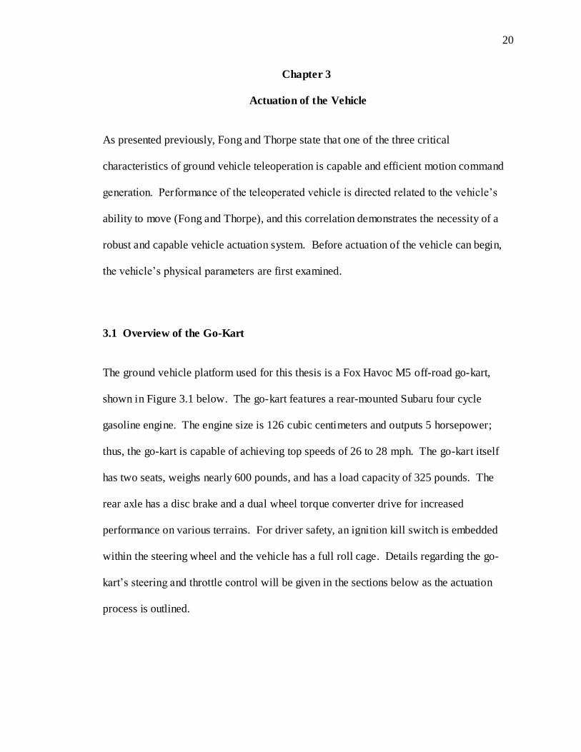
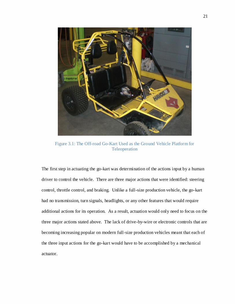
The ground vehicle platform used for this thesis is a Fox Havoc M5 off-road go-kart,
shown in Figure 3.1 below. The go-kart features a rear-mounted Subaru four cycle
gasoline engine. The engine size is 126 cubic centimeters and outputs 5 horsepower;
thus, the go-kart is capable of achieving top speeds of 26 to 28 mph. The go-kart itself
has two seats, weighs nearly 600 pounds, and has a load capacity of 325 pounds. The
rear axle has a disc brake and a dual wheel torque converter drive for increased
performance on various terrains. For driver safety, an ignition kill switch is embedded
within the steering wheel and the vehicle has a full roll cage. Details regarding the go-
kart’s steering and throttle control will be given in the sections below as the actuation
process is outlined.
21
Figure 3.1: The Off-road Go-Kart Used as the Ground Vehicle Platform for
Teleoperation
The first step in actuating the go-kart was determination of the actions input by a human
driver to control the vehicle. There are three major actions that were identified: steering
control, throttle control, and braking. Unlike a full-size production vehicle, the go-kart
had no transmission, turn signals, headlights, or any other features that would require
additional actions for its operation. As a result, actuation would only need to focus on the
three major actions stated above. The lack of drive-by-wire or electronic controls that are
becoming increasing popular on modern full-size production vehicles meant that each of
the three input actions for the go-kart would have to be accomplished by a mechanical
actuator.

22
3.2 Steering the Go-Kart
Steering the go-kart proved to be the most formidable aspect of the actuation system. To
introduce the steering process, the go-kart’s physical parameters related to the steering
system are presented.
The steering system on the go-kart functions similarly to a common rack-and-pinion
steering system. A solid shaft extends from the steering wheel to a cross-linkage that
moves the wheels back and forth. However, rather than a rack-and-pinion connection,
the steering shaft is connected to the cross-linkage with a cantilever steering bar, seen in
Figure 3.2. As the steering wheel is rotated, the bar sweeps through the range of steering
angles and translates this range into the range of front tire steering angles. Thus, the
steering wheel angle directly corresponds to the front tire steering angle. If the steering
wheel is turned 30 degrees clockwise, the front wheels will also turn 30 degrees
clockwise. Milliken and Milliken refer to this 1:1 steering ratio as “the ultimate in fast
steering,” as it permits the driver to negotiate tight turns at high speeds with little steering
wheel travel (Milliken and Milliken). The go-kart allows just less than 45 degrees of
steering in either direction, limited by welded mechanical stops on the steering column.
Both wheels always have the same steering angle, so Ackermann steering geometry is not
present on this go-kart. Refer to Figure 3.3 for a view of the steering arm.

23
Figure 3.2: View of the Steering Column
Figure 3.3: View of the Steering Arm

24
With the go-kart stationary on a concrete surface, initial torque tests were performed to
determine correct steering actuator size. A digital force gauge was used to measure the
force needed to begin rotation of the steering wheel at various moment arms. The torque
needed to rotate the steering wheel could then be found by multiplying the recorded force
with its corresponding moment arm. The average torque was calculated to be 111.3 lb-in.
This value, of course, would be dependent on a number of influencing factors, including
tire inflation pressure, driving surface, speed, and weight inside the go-kart, among
others. The torque needed to steer the vehicle would indefinitely fluctuate depending on
the current states of the influencing factors for a given driving situation. As a general
rule of thumb, it can be assumed that the torque required for steering a stationary vehicle
will be higher than the torque required for steering a rolling vehicle.
Because of the 1:1 steering ratio and the inability of the steering column to rotate more
than 90 degrees of total travel, it was decided that a limited-travel rotational servomotor
would be implemented to steer the vehicle. This type of steering actuator is different than
most steering actuators used on full-size production vehicles. Full-size production
vehicles (that lack steer-by-wire capability) generally use DC motors for steering control.
Most cars have steering ratios between 10:1 and 20:1, so the steering wheel rotates 10 to
20 times more than the front wheels, resulting in hundreds of degrees of steering wheel
rotation. Only multiple-turn motors are suitable for this large range of motion, but for
vehicles like the go-kart, a servomotor with limited travel is sufficient enough to cover
the full range of steering wheel rotation.

25
The servomotor selected for steering control was the Tonegawa Seiko SSPS105, shown
in Figure 3.4. The particular model that was chosen has +/- 45 degrees of travel and is
capable of outputting 324 lb-in of torque. Such a servomotor is fairly easy to find, but
the SSPS105 has specific advantages for this work because of its high torque-to-size
ratio. The servo’s maximum torque is enough to adequately steer the vehicle under all
conditions, yet its small size is well-suited to the go-kart’s limited space for steering
actuator placement. The servo is approximately 5 inches by 5 inches by 2 inches in size
and is easily secured in position with four mounting holes. It has a speed of 90 degrees
per 0.9 seconds and requires 12 VDC for operation.
Figure 3.4: Tonegawa Seiko SSPS105 (Courtesy of Tonegawa Seiko)
With the servomotor in hand, the next task for steering actuation was to connect it to the
steering column and mount it in place. However, directly connecting the servo to the
steering column would be an unwise and dangerous mistake. Because this work involves
an offroad go-kart traveling at high speeds and performing quick, jerky maneuvers, there

26
is a constant risk of induced wheel lift and in extreme cases, vehicle rollover. Such an
event includes the possibility of forcefully impacting the front wheels of the go-kart,
causing them to turn quickly, thus inducing a very high torque back to the steering
column. A torque incurred on the servomotor beyond its rating could strip its internal
gearing or send a damaging current spike to the go-kart’s onboard electronics. To
alleviate this problem and protect the servomotor, the connection between it and the
steering column must include some sort of torque-limiting mechanism. The mechanism
would preserve the connection between the servo and steering column for relatively low-
torque actions, such as steering and minor bump steer, but would sever this connection if
a torque overload occurred.
Hobbyists face exactly the same type of torque-limiting problem with their R/C cars.
They must protect their steering servos in the event of rollover, or maybe even more
commonly, inexperienced hobbyists manually forcing the car’s front wheels back and
forth for fun. Most R/C hobby cars are equipped with a plastic “servo-saver” that absorbs
any sort of torque overload on the steering system. These mechanisms are readily
available and very inexpensive, but are only large enough to protect small hobby servos
that usually output less than 150 oz-in. Servo-savers are too small and too delicate for
this project, but provide a good model for what the torque-limiting device must
accomplish.
Multiple friction-type devices were considered for their simplicity and inexpensiveness.
“Friction-type devices” are classified here as devices that use friction to engage and

27
disengage torque transfer. Such devices include tensioned rubber disks riding on each
other, a V-belt pulley system, or some sort of friction clutch. All of these devices could
be tensioned so that low torques would pass and higher torques would cause the
disk/belt/clutch to slip. However, all of these devices would require timely
experimentation to determine the correct tensioning for given torque values, and would
most likely result in a loss of absolute positioning. Even slight slips in the system would
produce an “offset” in the steering. Offsets would be acceptable for steering actuation
systems that employed multiple-turn motors, but are undesirable for the task of steering a
vehicle using the limited-travel servomotor that was purchased for this project.
Thus, torque-limiting methods that preserve absolute positioning were researched. A
shear pin could be used to transmit the torque between the servo and steering column.
This pin would act like a rigid connection at low torques and would snap instantaneously
upon torque overloads. A second solution included an undersized timing belt that would
function very similarly, snapping immediately upon torque overloads. Both of these
solutions are inexpensive ways to eliminate possible offsets caused by slippage, but also
require timely experimentation for correct pin/belt sizing.
Despite being more costly, mechanical torque limiters like those offered from Browning,
Zero-Max, and R+W America proved to be the best choice. A model SK1 torque limiter
from R+W America was selected for implementation on the go-kart. The SK1 provides a
rigid coupling with zero backlash between the servomotor and steering column,
maintaining absolute positioning (until overload occurs). Once overload occurs, steel

28
balls inside the SK1 slide out of their tracks, disengaging the connection between the
drive and driven components. R+W America initially set the SK1 for disengagement just
above the torque capability of the servomotor at 40 N-m, equivalent to 354 lb-in.
However, the SK1 can be adjusted for precise overload torque values anywhere between
20 and 60 N-m. A drawing view of the SK1 is displayed in Figure 3.5.
Figure 3.5: R+W America SK1 Mechanical Torque Limiter (Courtesy of R+W America)
Now that the torque limiter was acquired, connection to the steering column could
commence. Initial objectives of the steering actuation system were as follows: preserve
the steering wheel and make the actuation system removable so that a human driver could
still operate the vehicle, provide an easy means for activating and de-activating the
actuation system, and mount the system in such a way that would not hinder a human
driver from sitting and operating the vehicle. The go-kart also had some physical
restrictions on the flexibility of connecting the servomotor. The steering shaft was
immovable and could only be accessed by removing the steering wheel. Only the few

29
inches of shaft between the steering wheel and go-kart frame are available for mounting
parts that needed to slide over the shaft.
With the objectives and physical restrictions in mind, it was decided that a timing belt
pulley would be a cheap, adequate solution to connect the servo to the steering column.
With the timing belt, the torque limiter and a pulley would mount on the steering column
just below the steering wheel and the steering wheel could be preserved by extending the
shaft. The belt would run to a parallel pulley mounted on the servomotor, held in place
by a welded aluminum bracket. Figure 3.6 and Figure 3.7 give a SolidWorks view and a
photo of the initial steering setup concept, respectively.
Figure 3.6: SolidWorks Model of Initial Steering Connection

30
Figure 3.7: Initial Steering Connection
After performing the necessary load and sizing calculations, a GT Power Grip timing belt
was selected for this application. The belt had a 5 millimeter pitch, width of 15
millimeters, and 90 teeth. To keep the 1:1 steering ratio described earlier, two timing belt
pulleys, with identical pitch diameters of 2.13 inches, were installed on the servomotor
and torque limiter. An aluminum coupler was machined to attach the torque limiter and
pulley, then the torque limiter was installed on the steering column. Positioning of the
aluminum servo bracket was determined by calculating the center distance (5.51 inches)
required for the timing belt and pulleys.
When the go-kart was lifted off the ground for the first radio-control tests (described in
detail in Chapter 4), the initial steering setup performed as expected. The timing belt
connection easily turned the front wheels to the desired steering angle, given that the

31
wheels were off the ground. As soon as the vehicle was placed back on the ground,
however, the static friction between the concrete surface and front wheels proved to be
too great for the steering system. To output a larger torque to turn the wheels, the
servomotor caused the welded aluminum bracket to flex significantly, resulting in poor
tensioning of the timing belt. The timing belt proceeded to jump on the pulleys, losing
absolute servo positioning and failing to steer the vehicle. The setup managed to steer the
vehicle as it moved (due to the lower friction on the wheels as they rolled), but the belt
frequently still jumped. Clearly, the steering system design needed revisions.
The lack of rigidity in the welded aluminum bracket was the prominent reason why the
initial steering setup failed. The flexing in the bracket caused the timing belt pulley to
loosen, thus rendering the center distance calculations for correct tensioning irrelevant
and useless. A new design would need to feature a more rigid mounting bracket that
could withstand the high torques needed to steer the vehicle. Also, eliminating the timing
belt would increase the possibility of building a successful system because no tensioning
problems would arise. The objectives of the steering system were revised to
accommodate the necessary revisions in the steering system design. The new objectives
focused more on steering system performance rather than accommodation of a human
driver. The revised objectives were as follows: make the system as simple as possible to
alleviate unnecessary design complications, provide a strong and rigid mount for the
servomotor, and leave options open for the future installation of a steering wheel. Surely,
these objectives better outlined a plan to provide capable and efficient motion command

32
generation to the vehicle, which, as stated previously, is a critical aspect of successful
teleoperation.
It was decided that the optimal solution for mounting the servomotor was to construct a
large box frame that could anchor to various points on the go-kart. The anchor points
would provide lateral stability to the frame to counteract the high torque output by the
servomotor. The servomotor, with a machined aluminum coupler, could connect directly
to the torque limiter installed on the steering column, removing the timing belt and
related problems with tensioning, and drastically increasing the chances of successful
steering. This alteration would also concentrically line up the servomotor axis and
steering column axis, relieving the servomotor from any additional stresses caused by
moments on its output shaft.
The box frame to mount the servo was constructed from aluminum profiles from 80/20
Inc. The profiles are easily cut to length and fastened with nuts and bolts also from 80/20
Inc., like a large industrial erector set. 80/20 provided specific advantages for the
servomotor frame, given its high rigidity, adjustability, and versatility. SolidWorks
model views of the servo mounting frame are shown in Figure 3.8 and Figure 3.9.

33
Figure 3.8: Isometric SolidWorks View of the Servo Mounting Frame
Figure 3.9: Right Side SolidWorks View of the Servo Mounting Frame
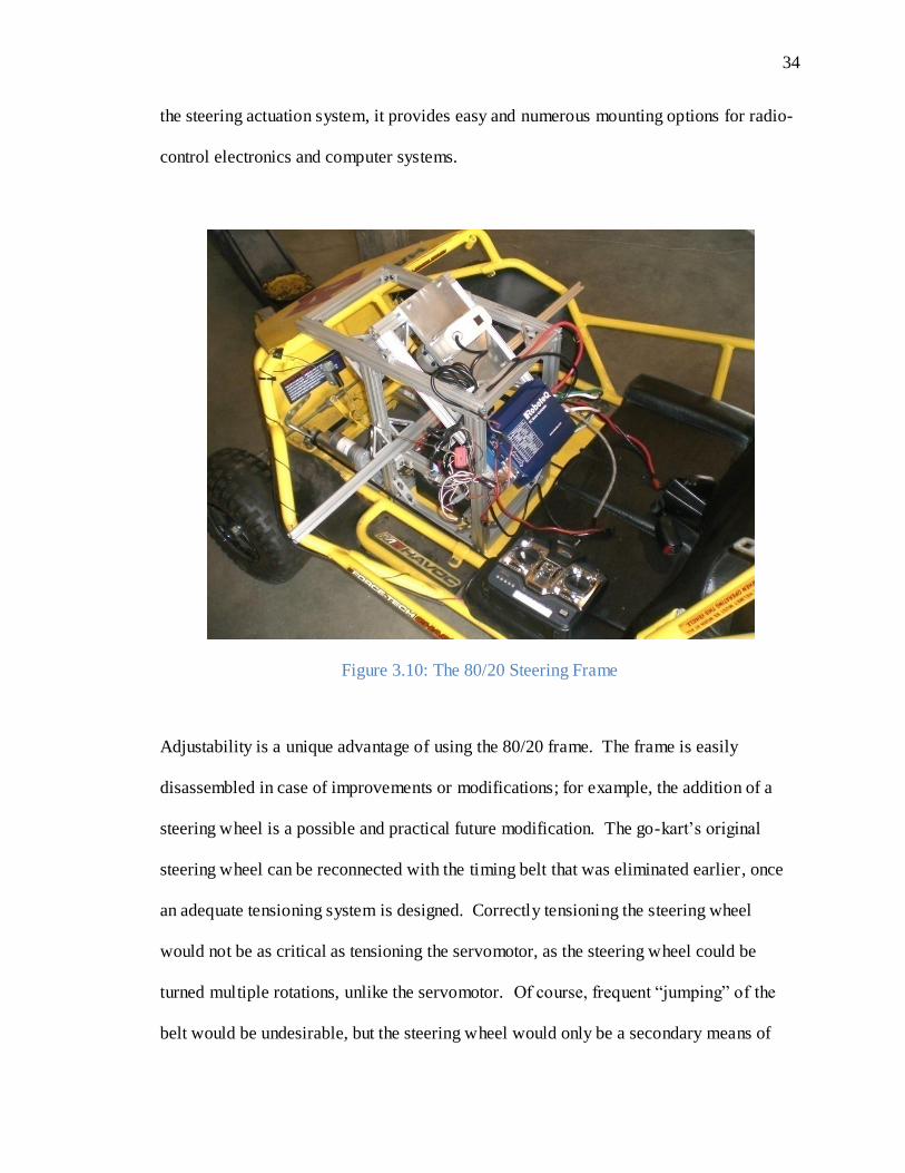
A 42 inch length of profile was secured laterally across the vehicle for additional support,
shown in Figure 3.10. Not only did the new 80/20 frame provide strength and rigidity to
34
the steering actuation system, it provides easy and numerous mounting options for radio-
control electronics and computer systems.
Figure 3.10: The 80/20 Steering Frame
Adjustability is a unique advantage of using the 80/20 frame. The frame is easily
disassembled in case of improvements or modifications; for example, the addition of a
steering wheel is a possible and practical future modification. The go-kart’s original
steering wheel can be reconnected with the timing belt that was eliminated earlier , once
an adequate tensioning system is designed. Correctly tensioning the steering wheel
would not be as critical as tensioning the servomotor, as the steering wheel could be
turned multiple rotations, unlike the servomotor. Of course, frequent “jumping” of the
belt would be undesirable, but the steering wheel would only be a secondary means of

35
steering the vehicle. Teleoperation is only dependent on successful operation of the
servomotor, not the steering wheel, and hence this tradeoff is acceptable.
The performance of the new steering actuation system was much better and more robust
than the initial timing belt connection method. Radio-controlled, the servomotor was
able to turn the front wheels on command, even with the vehicle stationary and with the
wheels down on a surface. Full discussion of radio control of the go-kart is given in
Chapter 4.
3.3 Throttle and Brake Actuation
Focus is now turned to the other two input commands to the vehicle: throttle and brake.
Compared to the steering, actuating the throttle and brake is much more straightforward.
As the throttle and brake pedals on the go-kart were very similar, their actuation systems
were constructed very similarly. To introduce their actuation, the physical parameters of
the pedals and cables on the vehicle are first presented.
The pedals that control the throttle and brake are mirror opposites of each other, with the
throttle pedal mounted for the right foot and brake pedal mounted for the left foot. The
pedals pivot at the floor of the go-kart from the hollow tube frame and rise 5 inches to the
pads for the driver’s feet. Three quarter-inch mounting holes are positioned along the
pedal at 1 inch, 1.5 inches, and 2 inches from the pivot point. Small metal stops are
welded onto the tube frame to only permit approximately 30 degrees of travel for each
pedal. A torsion spring centered around the pivot point returns each pedal to its initial

36
position when no activation load is applied. Throttle control is regulated by a thin cable
that attaches to the middle mounting hole on the pedal, while the brake line is a hard line
that runs from the disc brake on the rear axle to the uppermost mounting hole on the
pedal. Views of the throttle and brake pedals are shown in Figure 3.11 below.
Figure 3.11: Brake and Throttle Pedals (respectively)
As with the steering, initial force tests were executed to determine the correct actuator
sizing for throttle and brake control. A digital force gauge was used to push each pedal
through its entire stroke at 2 inches above its pivot. The maximum force needed to
perform this task was recorded. Nearly all of the resistance to pushing the pedals was
due to the torsion springs; the pedals and cables alone are practically effortless to engage.
However, the tests were performed with the torsion springs in place to ensure the
actuators would easily be able to control pedal position, no matter the setup. It was found
that the throttle pedal needed a maximum force of 20.5 pounds to push through its stroke,
and the brake pedal required a maximum force of 16.9 pounds.
37
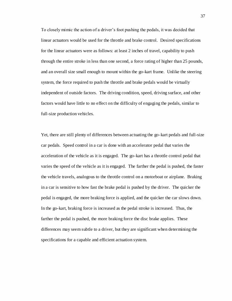
To closely mimic the action of a driver’s foot pushing the pedals, it was decided that
linear actuators would be used for the throttle and brake control. Desired specifications
for the linear actuators were as follows: at least 2 inches of travel, capability to push
through the entire stroke in less than one second, a force rating of higher than 25 pounds,
and an overall size small enough to mount within the go-kart frame. Unlike the steering
system, the force required to push the throttle and brake pedals would be virtually
independent of outside factors. The driving condition, speed, driving surface, and other
factors would have little to no effect on the difficulty of engaging the pedals, similar to
full-size production vehicles.
Yet, there are still plenty of differences between actuating the go-kart pedals and full-size
car pedals. Speed control in a car is done with an accelerator pedal that varies the
acceleration of the vehicle as it is engaged. The go-kart has a throttle control pedal that
varies the speed of the vehicle as it is engaged. The farther the pedal is pushed, the faster
the vehicle travels, analogous to the throttle control on a motorboat or airplane. Braking
in a car is sensitive to how fast the brake pedal is pushed by the driver. The quicker the
pedal is engaged, the more braking force is applied, and the quicker the car slows down.
In the go-kart, braking force is increased as the pedal stroke is increased. Thus, the
farther the pedal is pushed, the more braking force the disc brake applies. These
differences may seem subtle to a driver, but they are significant when determining the
specifications for a capable and efficient actuation system.

38
Two identical model FA-35-S-12-3” linear actuators from Firgelli Automation were
purchased to actuate the throttle and brake pedals. These actuators are rated at a
maximum of 35 pounds of pushing force and 400 pounds of static holding force,
adequate enough to provide successful position command to the pedals even with the
torsion springs in place. They have a no-load speed of 2 inches per second and a total
stroke extension of 3 inches. They are powered with 12 VDC and can be conveniently
mounted with quarter-inch clevis mounts on each end, making mounting to the pedals a
simple process.
Actuator mounting brackets were also purchased from Firgelli Automation to fasten the
linear actuators to the floor of the vehicle. Thin raising plates were machined to position
under the mounting brackets, lifting the linear actuators to a height where they could
extend perpendicular to the moment arm of the pedals. With this configuration, the
actuators would operate most efficiently. At first, limit switches were wired into the
actuator power circuit to prevent the actuators from extending into the welded metal
stops. These switches were later removed. Commanding the actuators into the
mechanical stops harms neither the actuators themselves nor any electronic components.
Thus, removing the switches was beneficial to the performance of the vehicle, as the
throttle and brake control could both be pushed to the maximum level, as would be done
by a human driver. Refer to Figure 3.12 and Figure 3.13 for views of the linear actuators
mounted on the vehicle.

39
Figure 3.12: SolidWorks Model of Linear Actuators
Figure 3.13: View of the Linear Actuators
40
It is important to note that the torsion springs were removed from the pedals as well.
Their purpose is no longer needed with the linear actuators; the actuators must be
commanded to extend and retract. Unlike a human foot, the clevis mounts on the linear
actuators allow them to pull the pedals just as well as they can push the pedals. It is
difficult and very unsafe for a human to pull the pedals back to a certain position, so the
torsion springs do this job instead. The driver needs only to focus on pushing. With the
springs removed, the linear actuators have very little resistance to controlling the position
of the pedals. As a result, their actuation performance is bettered by allowing them to
operate at higher speeds and lower motor currents.
Equipping the vehicle with an actuation system is a preliminary, but extremely important,
step of developing a platform for teleoperation. Without capable and efficient actuation,
teleoperation is not only destined to fail, but very difficult to even set in motion. All of
the design iterations with the actuation system must be completed before beginning to
develop a computer structure for wirelessly controlling the ground vehicle. In order to
test the actuation system, a simple and safe testbed is needed. In the case of this off-road
go-kart, radio control is a sufficient method for assessing the capability of the actuation
system, while still closely monitoring the vehicle. The next chapter focuses on radio
control of the go-kart, and the valuable lessons learned during its testing.
41
Chapter 4
Radio Control of the Vehicle
Radio control (R/C) of the vehicle is especially advantageous for testing because of its
short setup time and relatively simple configuration. Before the vehicle was outfitted
with the R/C components, though, objectives for this phase of the development were
established. First and foremost, the goal of R/C control of the vehicle is to remotely
command the steering, throttle, and brake, and ensure proper functioning of the entire
actuation system. Other objectives are as follows: iterate the actuation design if
necessary, target additional safety measures for the teleoperated vehicle, and prepare the
system for computer control. Ultimately, the R/C testing may only be a stepping stone
toward the goal of producing a teleoperated off-road vehicle. Thus, it is imperative that
all possible debugging occur at this stage, when the system complexity is still low.
4.1 Overview of the Radio Control System
The first issue to address for controlling the vehicle is determining how to command the
linear actuators. Commanding the steering servomotor is straightforward, as it includes a
standard PWM (pulse width modulation) input. Conversely, the linear actuators lack
some sort of position command input, and contain only leads running to their DC motors.
Wiring the leads to a power source extends the actuator arm, and reversing the polarity of
the leads retracts it. The best solution is to command the linear actuators with a DC
motor controller. The motor controller can process the PWM input from the R/C signal,
and command the actuators accordingly.
42
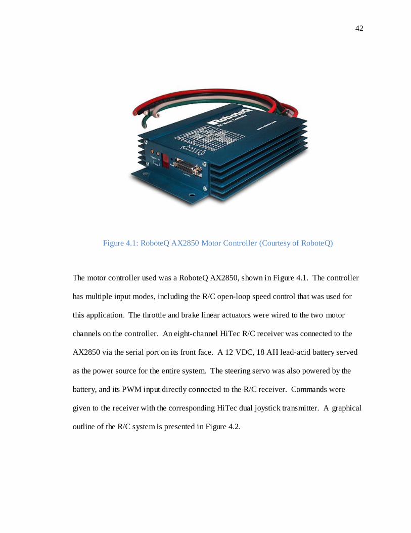
Figure 4.1: RoboteQ AX2850 Motor Controller (Courtesy of RoboteQ)
The motor controller used was a RoboteQ AX2850, shown in Figure 4.1. The controller
has multiple input modes, including the R/C open-loop speed control that was used for
this application. The throttle and brake linear actuators were wired to the two motor
channels on the controller. An eight-channel HiTec R/C receiver was connected to the
AX2850 via the serial port on its front face. A 12 VDC, 18 AH lead-acid battery served
as the power source for the entire system. The steering servo was also powered by the
battery, and its PWM input directly connected to the R/C receiver. Commands were
given to the receiver with the corresponding HiTec dual joystick transmitter. A graphical
outline of the R/C system is presented in Figure 4.2.

43
Figure 4.2: The System Layout for R/C Control
The R/C system was first implemented on the go-kart with the original timing belt
steering setup. Radio control of the vehicle allowed for testing, making it possible to
discover the problems with the timing belt tensioning. Other additional issues were
discovered as well: the vehicle needed some sort of redundancy to prevent the system
from losing control. There were a few concerns with leaving the R/C setup the way it
was first installed. For example, if the go-kart traveled out of range of the radio
transmitter with the throttle engaged, there would be no way to command its return. The
vehicle would proceed to “run away,” immediately endangering other people and
bringing about an extremely high probability of crashing into obstacles like trees or
buildings, or navigating undesirable terrain features like ditches or steep slopes. Clearly,
additional safety measures were needed.
44
4.2 Improvement Identification and Design Revision
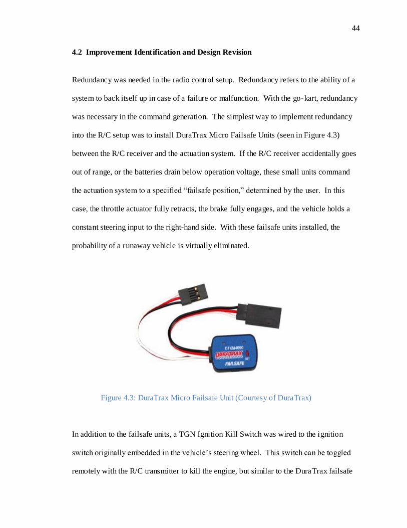
Redundancy was needed in the radio control setup. Redundancy refers to the ability of a
system to back itself up in case of a failure or malfunction. With the go-kart, redundancy
was necessary in the command generation. The simplest way to implement redundancy
into the R/C setup was to install DuraTrax Micro Failsafe Units (seen in Figure 4.3)
between the R/C receiver and the actuation system. If the R/C receiver accidentally goes
out of range, or the batteries drain below operation voltage, these small units command
the actuation system to a specified “failsafe position,” determined by the user. In this
case, the throttle actuator fully retracts, the brake fully engages, and the vehicle holds a
constant steering input to the right-hand side. With these failsafe units installed, the
probability of a runaway vehicle is virtually eliminated.
In addition to the failsafe units, a TGN Ignition Kill Switch was wired to the ignition
switch originally embedded in the vehicle’s steering wheel. This switch can be toggled
remotely with the R/C transmitter to kill the engine, but similar to the DuraTrax failsafe
Figure 4.3: DuraTrax Micro Failsafe Unit (Courtesy of DuraTrax)

45
units, it also kills the engine upon sensing a signal loss. Now, if the go-kart travels out of
range, the actuation system will return to a failsafe position and the engine will turn off.
Levels of redundancy may sometimes seem unnecessary, but in reality, they represent a
well-planned and safe system. The redundancy levels on the go-kart made it possible to
test the performance of the R/C system with confidence that the vehicle would be
controlled at all times.
When the 80/20 steering frame was constructed and the servomotor mounted in-line with
the go-kart steering shaft, the R/C system was once again employed for testing.
However, despite better steering performance, even more problems with the steering
actuation were discovered. Only a few minutes into testing, the steering servomotor
failed to respond to any input commands. Even with no resistance to turning, the
servomotor was lifeless. The servomotor was subsequently removed from the vehicle
and disassembled for failure analysis. Dissection of the mechanism unveiled the cause of
the failure: the internal DC motor had overheated to the point where the wiring failed,
most likely caused by a damaging amount of commanded current. Further investigation
into the servomotor specifications revealed that the servomotor would damage itself if
commanded into a hard mechanical stop. Installed on the go-kart, the steering shaft
restricted the servomotor from exercising its full range of travel. Thus, whenever the
vehicle was commanded into a hard left or right turn during testing, the servo would meet
the mechanical stop, but continue to draw current to its motor to try to turn it farther.
This constant increase in current proceeded to fry the motor coils, permanently damaging
the servomotor and rendering it useless. The torque limiter did not prevent this type of

46
damage, as it was preset to a torque value higher than the capability of the servomotor.
Unfortunately, the steering system would have to be revised once again, this time with a
new actuation method.
Depleting funds and fast-approaching deadlines made the decisions for the new steering
actuator the hardest decisions to date. Replacing the damaged servomotor with an
identical one was out of the question. The extended lead time for ordering another
servomotor could not be accommodated, and it was also too expensive, especially for a
product that failed so quickly in the application on a remotely-controlled vehicle.
Instead, geared DC motors were researched. A motor of equivalent size and torque rating
could be obtained at a significantly cheaper price.
The AME 226 Series gearhead motor (Figure 4.4) was purchased for use as the new
steering actuator. With a maximum torque output of 36.7 N-m (325 lb-in) and nominal
voltage of 12 VDC, it is practically the exact size of the servomotor. At its highest speed,
the AME 226 spins at 96 rpm, making it capable of turning the steering shaft many times
faster than the servomotor. However, the geared motor lacks a position feedback
mechanism that the servomotor included. Servos are equipped with a potentiometer that
measures the output shaft position and matches it to the input command. With the new
geared motor, position feedback would have to be implemented using closed-loop
control.

47
Figure 4.4: The AME 226 Series Gearhead Motor (Courtesy of AM Equipment)
Along with the separate position feedback, the geared motor did not include a command
input like the servomotor had. There are only two leads running to the motor, similar to
the linear actuators. Thus, this motor would also have to be commanded by an outside
motor controller, and could not be wired directly to the R/C receiver like the servomotor.
The RoboteQ AX2850 would suffice for this application, except that the two linear
actuators already occupy its two motor channels. However, after careful consideration, it
was decided that the new steering motor could replace the brake actuator on one of the
channels. During the brief R/C testing phase, the brake actuator proved to function best
in one of two states: fully on or fully off. The actuator ended up being wired to a simple
toggle switch on the transmitter, rather than a joystick that commanded the input to the
actuator proportional to its position. Such a basic use of the linear actuator did not
demand the full capability of the AX2850 for its successful performance. Thus, a
RCE220 Dual Relay Switch was purchased to control the brake actuator. This small,

48
inexpensive switch can connect directly to the R/C receiver and process the input signal
into a simple extend or retract command – perfect for braking the vehicle. With this
change, the second channel on the AX2850 was freed for use with the geared steering
motor.
The last area that was identified for improvement during R/C testing was the throttle
control. With the throttle actuator wired in its initial setup (shown in Figure 4.2), the
linear actuator would continue to extend when the transmitter joystick was pushed
slightly forward, and retract fully back when the transmitter joystick was pulled even
slightly back. This setup proved to be quite problematic for speed control. A more
intuitive and convenient control method was desired. By implementing a position
feedback device on the throttle pedal, the linear actuator can be commanded to a specific
position, correlating directly to a specific go-kart speed. This position, and speed, would
be proportional to the joystick position on the R/C transmitter. This method was also the
exact kind of feedback control necessary for the steering motor. However, these control
algorithms would have to be programmed into a computer that would then be installed on
the vehicle, as the go-kart had no other “brains.”
In order for performance testing of the actuation system to resume, computer control was
necessary. Installing such a system on the vehicle greatly increases its complexity, but
allows for a wider range of safety measures, performance commands, and data
measurement capabilities. The necessity for a more complex system is the topic of the
next chapter: computer control of the vehicle.
49
Chapter 5
Computer Control of the Vehicle
Implementation of a computer on the vehicle was expedited because of the need to install
simple control loops for the steering and throttle. The vehicle could not be successfully
driven, and thus tested, until these control loops functioned correctly. As an added
benefit, implementing a computer provides a convenient method for recording all types
of data. Evaluation and assessment of a teleoperated vehicle is better accomplished with
data that represents its performance. Gathering this data is much easier with a computer
mounted directly on the go-kart.
5.1 Overview of the Computer Control System
All of the same components that were used for R/C control of the vehicle were preserved
for computer control as well. Of course, the biggest and most important addition to the
vehicle was the Athena single-board computer from Diamond Systems. For data
acquisition, connected to the Athena was the Diamond-MM-32X-AT analog input/output
module. Together, this computer features 32 single-ended or 16 differential analog inputs
and four analog outputs. The analog inputs and outputs serve as the portals for data
acquisition, necessary for both successful implementation of closed-loop control and
recording vehicle performance data. The entire computer is less than five inches square
by five inches tall, so it fits very well on the go-kart and can be easily secured to the
existing 80/20 frame. The Athena supports the MATLAB/Simulink xPC Target
software, which was used for this application. Communicating with the Athena through

50
the xPC software provides a real-time communication link for implementation of the
throttle and steering control loops and for capturing data. The xPC software is
specifically advantageous because the control loops can be designed in Simulink with
simple block diagrams, then built, compiled, and downloaded into the Athena. There is
no need to write long computer language codes that are often troublesome for
inexperienced programmers. With the computer in place, the actuation and control
system can then be developed to rely on the computer’s analog inputs and outputs.
Before the rest of the computer control system was developed, objectives for this phase
of the vehicle development were listed. First and foremost, the main goal of the
computer control of the go-kart was to demonstrate the successful performance of the
vehicle’s actuation system. Performance analysis is best accomplished with hard data
validation, thus the second objective was to accurately record data related to the vehicle’s
throttle and steering response. Yet, correct functioning of the throttle and steering
actuators depended on the correct functioning of the closed-loop control needed for their
command, bringing about the third objective. The final objective was to establish a
computer architecture that would accommodate future changes and additions, including
some degree of local autonomy, additional safety measures, and programs necessary for
wireless control.
For this testing phase, it was desirable to keep the R/C transmitter as the method of
generating commands to the actuation system. Thus, the first step toward computer
control was developing a way for the computer to sense the R/C transmitter signal. Radio
51
control signals are PWM signals, where the pulse width is proportional to the command.
For example, moving the joystick all the way to the left sends a pulse with a one
millisecond width. These pulses are repeated every 18 to 20 milliseconds. Moving the
joystick all the way to the right sends pulses with 2 millisecond widths. Pulses of 1.5
milliseconds are representative of the middle position. Since the computer was equipped
with analog inputs, a device is needed that reads the pulse width and sends a
corresponding analog voltage to the computer. For most PWM applications, passing the
signal through a low-pass filter is an adequate and simple method for converting to a DC
voltage. However, the R/C transmitter only sends pulses every 20 milliseconds; passing
this signal through a filter would yield only minor variations in voltage between “left”
and “right” commands.
The best solution to convert RC signals to analog is to use a microchip like the BASIC
Stamp or Microchip PIC. These chips are capable of counting the width of pulse inputs
and outputting a PWM signal with a much higher duty cycle. This signal could then be
filtered as described above. However, with deadlines approaching, there was not enough
time to develop a circuit that included one of these chips. A faster, more convenient
method was sought.
The quickest method for converting the R/C signal to a DC voltage was to use a
mechanism that already implemented this conversion: a small Futaba servomotor. The
servomotor directly accepts the R/C signal and turns its internal motor until it reaches the
corresponding position. It uses its own potentiometer feedback to determine this
52
position. Hence, the potentiometer outputs a voltage proportional to the R/C signal. By
opening the servomotor and tapping its potentiometer, an analog voltage can then be
brought to the computer’s inputs. Because the computer needs to execute two control
loops for the steering and throttle, two Futaba servos were modified.
The control loops for the steering and throttle actuators required their own position
feedback devices. Potentiometers are the simplest feedback devices and ideal for this
application. They provide an analog voltage proportional to their position, exactly the
type of input that the computer requires. Connecting a potentiometer to the throttle pedal
was straightforward: by extending the shaft on which the pedal pivots, the potentiometer
was connected with a flexible coupler and fastened on an aluminum bracket to the floor
of the vehicle. Connecting the steering potentiometer was not as simple since there were
no available direct mounting configurations. Instead, the steering potentiometer had to be
connected indirectly. The potentiometer shaft was inserted into a wide rubber wheel and
positioned so that it rubbed on the coupler between the steering motor and torque limiter.
The setup was held in place with a bracket made from 80/20 parts and mounted to the rest
of the steering frame. A view of the steering potentiometer is given below in Figure 5.1.

53
Figure 5.1: The Steering Feedback Potentiometer
With all the necessary components in place, the computer control program could now be
developed. The control loops for the steering and throttle were diagramed in
MATLAB/Simulink using the xPC Target blockset. Closed-loop proportional control
algorithms were implemented for both steering and throttle control because of their
simplicity and sufficiency. The more complex forms of derivative or integral control did
not need to be included for the basic testing of this thesis. Figure 5.2 shows the control
loops, as they were developed in Simulink. Notice that the control command includes a
2.5 V offset, as the analog inputs on the RoboteQ AX2850 use 2.5 V as their middle
position. The analog inputs on the motor controller vary between 0 and 5 V, thus the
control command was catered to this parameter.

54
Figure 5.2: Closed-Loop Steering and Throttle Control
Before the entire computer control system was installed on the vehicle, correct
functioning of the system was tested in the lab. When correct functioning was verified,
the system was transferred to the go-kart for gain tuning and improved filtering for more
accurate feedback information. The computer control system layout is presented in
Figure 5.3. Other than the components needed for feedback control, the same
components from the R/C control system were used. However, with the computer
involved, the capabilities of the vehicle actuation increase dramatically.
MM-32
Diamond
Analog Input
1
Throttle Reference
MM-32
Diamond
Analog Input
1
Throttle Feedback
MM-32
Diamond
Analog Output
1
Throttle Control Command
MM-32
Diamond
Analog Input
1
Steering Reference
MM-32
Diamond
Analog Input
1
Steering Feedback
MM-32
Diamond
Analog Output
1
Steering Control Command
In1 Out1
Reference Signal Conditioning T
In1 Out1
Reference Signal Conditioning S
K
Proportional Control Gain T
K
Proportional Control Gain S
In1Out1
Feedback Signal Conditioning T
In1Out1
Feedback Signal Conditioning S
u+2.5
Bias T
u+2.5
Bias S

55
Figure 5.3: The Computer Control System Layout
Installing the computer system on the go-kart proved to be quite a delicate task. All the
components had to be secured tightly and protected in case of collision, especially the
Athena computer. Still, the go-kart had limited space for mounting, complicated by the
desire to have all the components accessible for easy troubleshooting. With these
objectives in mind, securing the components required careful planning and cautious
work. The 80/20 steering frame was a convenient mounting base, but also obstructed
possible mounting configurations. However, after hours of fastening and wiring, the
vehicle was fully equipped (see Figure 5.4) and testing of the system could begin.

56
Figure 5.4: The Vehicle Equipped for Computer Control
5.2 Testing of the Computer Control System
Computer control testing began with the vehicle stationary on the ground and the engine
off. Before the R/C transmitter was used, sine wave commands were generated by the
computer to ensure that the actuation system was functioning properly. The actuators
responded as they should, oscillating between their two command extremes. It is
important to note that the steering shaft was not connected to the steering motor at this
point. The connection between the coupler and torque limiter was left undone to prevent
any undesirable effects if the steering motor failed to function as it should. When correct
functioning of the actuation system was observed, the Simulink program was modified to
respond to the R/C transmitter signal and the steering shaft was connected. Commands
from the transmitter were recorded on the Athena and sent to a laptop computer with a

57
crossover cable. Actuator feedback was recorded simultaneously so the system response
could be displayed graphically on MATLAB plots. These plots are ideal for evaluating
the performance of the closed-loop steering and throttle control and are good tools for
predicting the performance of the vehicle when driven. Data was collected for a number
of initial tests, and is presented below.
Data related to the performance of the steering and throttle control loops was collected
and evaluated graphically. Figure 5.5 presents a plot of the throttle response, governed
by the closed-loop control implemented by the Athena computer. This plot verifies the
correct functioning of the control loop, as the actual position of the throttle pedal follows
the commanded position from the R/C transmitter. The actual throttle control signal sent
by the computer to the motor controller is given in Figure 5.6. As stated earlier, a signal
of 2.5 V corresponds to the “middle position,” or signal that results in no action. The
actual throttle position is presented along with the control command for reference.

58
Figure 5.5: Throttle Tracking Response Plot
Figure 5.6: Throttle Control Command Plot
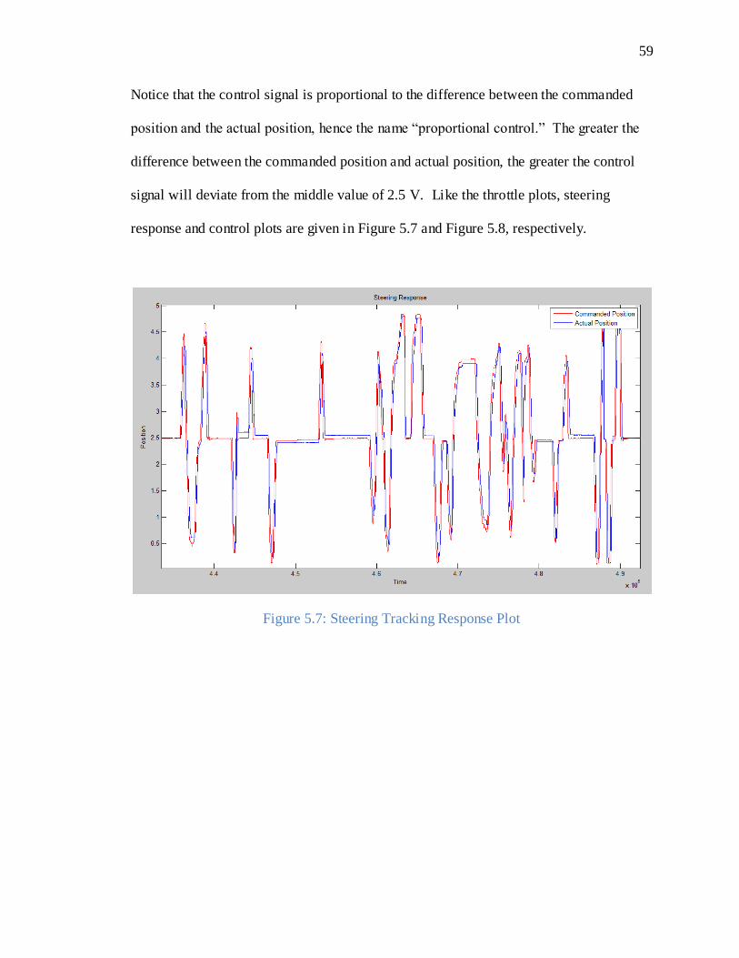
59
Notice that the control signal is proportional to the difference between the commanded
position and the actual position, hence the name “proportional control.” The greater the
difference between the commanded position and actual position, the greater the control
signal will deviate from the middle value of 2.5 V. Like the throttle plots, steering
response and control plots are given in Figure 5.7 and Figure 5.8, respectively.
Figure 5.7: Steering Tracking Response Plot

60
Figure 5.8: Steering Control Command Plot
The plots above validate the correct functioning of the closed-loop control, and provide
confidence in the computer control of the vehicle. Once again, the go-kart was taken for
another test drive, this time with complete success. The vehicle responded quickly to
commands and the computer functioned properly, as did all other components of the
system. Still, multiple aspects of the vehicle were identified for improvement.
5.3 Identification of Areas for Improvement
Throughout the computer control testing phase, two major areas for improvement were
recognized. First, the Futaba servomotors contributed to a number of problems. The
small servomotors draw all of their power from the R/C receiver, as they have no other
power wires. Initially, the R/C receiver was only powered from the 5 V output on the

61
Roboteq AX2850 motor controller. This meant that the AX2850 also powered the two
servomotors, an application for which it was not designed. The servos often drew too
much current from the AX2850, and the motor controller would fail to accept the actuator
control commands from the computer. Thus, the whole system failed. A simple solution
was realized: power the R/C receiver from an external 5 V power supply. This power
supply also powered the Athena computer, so it was available and already secured to the
vehicle. Once this change was made, the motor controller ably commanded the actuators
from the computer control signals.
The second area for improvement was the lack of a steady power source. Almost all of
the components on the vehicle were powered by a single 12 V 18 AH lead-acid battery.
It was soon discovered that this single battery lost charge quickly, and numerous
problems resulted. Most noticeably and probably most importantly, the feedback
potentiometers were wired to this battery, thus their signal voltage varied depending on
the charge of the battery. This variation disrupted the control loops, as they relied on
accurate feedback voltages to produce a control command. Surely, this was an issue that
would have to be addressed in the next design revision.
Overall, the computer control of the vehicle proved to be successful. After much
planning, construction, and troubleshooting, the closed-loop control performed as
expected when implemented on the vehicle. The vehicle was driven once again, but this
time using a system with much higher complexity. The added complexity allows the
continuation of the go-kart development toward greater capabilities, and ultimately, long-
distance teleoperation.

62
Chapter 6
Conclusion
The goal of this thesis was to develop a ground vehicle platform to be used for
teleoperation. While teleoperation has not yet been accomplished, development of the
ground vehicle platform can be considered a success. The off-road go-kart that was used
for this project was transformed into a remotely-guided vehicle, complete with capable
actuation and computer architecture to support wireless control. These results lay the
groundwork for teleoperation to be achieved in the future.
Development of the vehicle did not go smoothly, and many lessons were learned in this
process. Unforeseen obstacles were encountered that hindered progress, and even caused
many design aspects of the vehicle to be iterated over and again. It was learned that even
the best computer-aided drafting design of the go-kart and its actuation system cannot
predict mechanical malfunctions. The steering setup failed twice, proving that optimal
solutions can take time to develop. Computer control, while the most complex phase of
the project, produced the most desirable results, proving that increasing complexity can
increase performance when done correctly. Funds depleted and deadlines were pushed,
yet all of these factors still contributed to the development of a vehicle that met its
objectives. Because of the work that is described in this thesis, new possibilities can be
explored in the field of unmanned ground vehicles, particularly teleoperated vehicles.

63
6.1 Future Work
Outlined below are some of the tasks that still need to be addressed on this project. Some
tasks reflect improvements that should be made on the existing vehicle and some
represent the next steps to be addressed on the way to teleoperation.
Replace the Futaba servomotors with a microchip to count the pulse width of an
incoming R/C signal
Implement additional safety measures on the computer program
Place emergency stops buttons around the outside of the vehicle for safety
Route the brake signal through the computer, like the throttle and steering
commands
Power the feedback potentiometers off a regulated voltage supply so their
feedback signal is more accurate
Begin to develop a computer architecture to support wireless control of the
vehicle
Implement additional sensors like LIDAR on the vehicle

64
REFERENCES
Association, Advanced Cruise-Assist Highway System Research. Cruise Assist Systems
Demonstrations Around the World. 2008. June 2008
<http://www.ahsra.or.jp/eng/c08e/index_f3_e.html>.
Babic, Josip, Marko Budisic and Ivan Petrovic. "Dynamic Window Based Force
Reflection for Safe Teleoperation of a Mobile Robot via Internet." IEEE/ASME
International Conference on Advanced Intelligent Mechatronics (2007): 1-6.
Bertozzi, Massimo, Alberto Broggi and Alessandra Fascioli. The ARGO Autonomous
Vehicle. Parma, Italy: Dipartimento di Ingegneria dell'Informazione, Universita di Parma,
1999.
Bertozzi, Massimo, et al. "Artificial Vision in Road Vehicles." Proceedings of the IEEE
(2002).
Blackburn, M. R., R. T. Laird and H. R. Everett. Unmanned Ground Vehicles (UGV)
Lessons Learned. San Diego, CA: SPAWAR Systems Center, 2001.
Fenton, Robert E and Robert J Mayhan. "Automated Highway Studies at The Ohio State
University - An Overview." IEEE Transactions on Vehicular Technology (1991).
Fong, Terrence and Charles Thorpe. "Vehicle Teleoperation Interfaces." Autonomous
Robots (2001): 9-18.
Gage, Douglas W. "UGV History 101: a Brief History of Unmanned Ground Vehicle
(UGV) Development Efforts." Unmanned Systems Magazine (1995).
Grange, Sebastien, Terrence Fong and Charles Baur. "Effective Vehicle Teleoperation on
the World Wide Web." Proceedings of the IEEE International Conference on Robotics &
Automation (2000): 2007-2012.
Jochem, Todd, et al. "PANS: A Portable Navigation Platform." IEEE Symposium on
Intelligent Vehicles (1995).
McWilliams, George T, et al. "Evaluation of Autonomy in Recent Ground Vehicles
Using the Autonomy Levels for Unmanned Systems (ALFUS) Framework." Proceedings
of the National Institute of Standards and Technology (NIST) Performance Metrics for
Intelligent Systems (2007).
Meyrowitz, Alan L, D. Richard Blidberg and Robert C Michelson. "Autonomous
Vehicles." Proceedings of the IEEE (1996): 1147-1164.
65
Milliken, William F and Douglas L Milliken. Race Car Vehicle Dynamics. Warrendale,
PA: SAE International, 1995.
Nielsen, Curtis W, Michael A Goodrich and Robert W Ricks. "Ecological Interfaces for
Improving Mobile Robot Teleoperation." IEEE Transactions on Robotics (2007).
Pezeshkian, Narek, Hoa G Nguyen and Aaron Burmeister. "Unmanned Ground Vehicle
Radio Relay Deployment System for Non-Line-of-Sight Operations." 13th IASTED
International Conference on Robotics & Applications (2007).
Pomerleau, Dean and Todd Jochem. No Hands Across America. 1995. June 2008
<http://www.cs.cmu.edu/afs/cs/usr/tjochem/www/nhaa/nhaa_home_page.html>.
Pomerleau, Dean. "RALPH: Rapidly Adapting Lateral Postion Handler." IEEE
Symposium on Intelligent Vehicles (1995).
Schmidhuber, Jurgen. Highlights of Robot Car History. 2007. June 2008
<http://www.idsia.ch/~juergen/robotcars.html>.
Schmidt, Rolf. "Autonomous Driving on Vehicle Test Tracks: Overview, Implementation
and Results." Proceedings of the IEEE Intelligent Vehicles Symposium (2000).
Seetharaman, Guna, Arun Lakhotia and Erik Philip Blasch. "Unmanned Vehicles Come
of Age: The DARPA Grand Challenge." IEEE Computer (2006).
Thrun, Sebastian, et al. "Stanley: The Robot that Won the DARPA Grand Challenge."
Journal of Robotic Systems (2006): 661-692.
"Transportation Accidents by Mode." Bureau of Transportation Statistics, U.S.
Department of Transportation. June 2008
<http://www.bts.gov/publications/national_transportation_statistics/html/table_02_03.ht
ml>.
"Transportation Fatalities by Mode." Bureau of Transportation Statistics, U.S.
Department of Transportation. June 2008
<http://www.bts.gov/publications/national_transportation_statistics/html/table_02_01.ht
ml>.
Urmson, Chris, et al. "Tartan Racing: A Multi-Modal Approach to the DARPA Urban
Challenge." 2007.
Wunsche, Joachim. "The Cognitive Autonomous Vehicles of UniBwM: VaMoRs, VaMP,
and MuCAR-3." 2007. Universitat der Bundeswehr Munchen. June 2008
<http://www.unibw.de/lrt13/tas/medien/elrob2007-
universitaetderbundeswehrmuenchen.pdf>.

66
APPENDIX
Products Purchased
Linear Actuators (2)
Firgelli Automation # FA-35-S-12-3”
Specifications: 3” stroke, 12 VDC, 35 lb, 2”/s
Price: $119.99 ea
http://www.firgelliauto.com/product_info.php?cPath=82&products_id=52
Servomotor (1)
Vantec # SSPS105S45
Specifications: Tonegawa Seiko, 27 ft-lb, +/-45 deg, 12 VDC, speed: 0.9 s/90 deg
Price: $524.95
http://www.vantec.com/ssps105.htm
Absolute Magnetic Kit Encoder
Digital (3)
US Digital # MAE3-P12-250-220-7
Specifications: 12-bit PWM output
Price: $50.90 ea
Analog (1)
US Digital # MAE3-A-250-220-7
Specifications: 10-bit analog output
Price: $43.90
http://www.usdigital.com/products/mae3/
Encoder Micro Connectors (4)
US Digital # CA-8703-1FT
Specifications: 3-pin connector, 26 AWG wires
Price: $5.00 ea
http://www.usdigital.com/products/connect/3pin-micro.shtml
Linear Actuator Mounting Brackets (2)
Firgelli Automation # MB1
Specifications: Clevis-pin triangular mount
Price: $18.00 ea
http://www.firgelliauto.com/product_info.php?cPath=70&products_id=54
Linear Actuator Wiring & Control Kit (2)
Firgelli Automation # EL-KIT
Specifications: external limit switches, 10A fuses, wiring
Price: $18.00 ea
http://www.firgelliauto.com/product_info.php?cPath=70&products_id=111
Torque Limiter (1)

67
RW-America # SK1/30/D/19.05/40/20-60/XX, XX = 30 deg re-engagement
Specifications: 40 N-m torque setting, zero backlash, 0.75” shaft, 30 deg re-engagement
Price: $292.04
http://www.rw-america.com/torque-limiters/torque-limiter-sk1_t.php
Timing Belt Pulleys (2)
McMaster-Carr # 6497K82
Specifications: 34 teeth, plain bore, 2.13” pitch diameter
Price: $48.80 ea
http://www.mcmaster.com/
Timing Belt (1)
McMaster-Carr # 7939K15
Specifications: Power Grip GT 5 mm, 450 mm outer circle, 90 teeth, 15 mm wide
Price: $16.60
http://www.mcmaster.com/
Misc. Parts
80/20 Inc.
Specifications: 10 Series aluminum profiles, drop-in T-nuts, corner brackets
Price: $760.90
http://www.8020.net/
Ignition Kill Switch (1)
Python Motor Sports # TGNfailkillswitch
Specifications: Loss of signal engine failsafe
Price: $38.95
http://www.pythonmotorsports.com/fg/offroad_parts/baja/Baja-5b-hopups.html
DuraTrax Micro Failsafe Units (3)
Tower Hobbies # LXHLV3
Specifications: Resettable failsafe signal
Price: $17.99 ea
http://www3.towerhobbies.com/cgi-bin/wti0001p?&P=9&I=LXHLV3
Geared Motor (1)
Robot Marketplace # AME-226-3003
Specifications: AM Equipment, 325 lb-in, 96 rpm, 12 VDC
Price: $67.99
http://www.robotmarketplace.com/products/AME-226-3003.html
Dual Relay Switch (1)
Robot Marketplace # 0-TD-RCE220
Specifications: Team Delta, relay load rating: 30 VDC, 12 A
Price: $37.99
http://www.robotmarketplace.com/products/0-TD-RCE220.html

68
Snapshots of the Vehicle in Action