Fabricating multifunctional microbubbles and nanobubbles - SPIE
Proceedings of 20th International Congress on Acoustics, ICA 2010
23-27 August 2010, Sydney, Australia
ICA 2010 1
The peculiar interactions of microbubbles and microvessels
Hong Chen, Andrew A. Brayman, and Thomas J. Matula Center for Industrial and Medical Ultrasound, Applied Physics Laboratory, University of Washington, Seattle, WA, USA
PACS: 43.35.-c 43.80.Vj
ABSTRACT
The application of microbubbles for both diagnostic macro- and molecular imaging and therapeudic ultrasound re-quires an understanding of the coupled interactions involving microbubble dynamics with the surrounding compliant microvessel. In this study, ultra-high speed microphotography was used to directly observe transient behaviors of mi-crobubbles in microvessels of ex vivo rat mesenteries. Definity® microbubbles were perfused through the vasculature, and then excited by a 2-µs long ultrasound pulse with a center frequency of 1 MHz with peak negative pressures be-tween 0.8–7.2 MPa. These amplitudes span the diagnostic to therapeutic pressure levels. During insonation, ultra-high speed images were captured with 50-ns exposure time and 150-ns or 300-ns interframe time. The recorded im-ages show a wonderful assortment of microbubble dynamics, including oscillation, translation, jetting, coalescence and fragmentation. These microbubble behaviors were coupled with the dynamic responses of the vessel wall, which showed distention, invagination, and even rupture.
INTRODUCTION
Ultrasound contrast agents are encapsulated gas bubbles with diameters on the order of a few microns. These microbubbles are injected into the blood circulation through intravenous injection. They have been successfully used in clinical ultra-sound imaging for more than two decades [1]. More recently, a range of new techniques have been developed to use micro-bubbles in both ultrasound imaging and therapy, such as mo-lecular imaging and drug/gene delivery. To develop effective techniques for the expanding applications of microbubbles, it is essential to understand their physical behavior inside actual blood vessels.
There have been intensive theoretical [2-4] and experimental [5-7] studies on microbubble dynamics in an infinite me-dium. Recently, there is increasing interest in investigating microbubble behaviors inside microvessels, as it has been shown that microbubbles can increase the permeability of microvessels to enhance local drug or gene delivery, and they can also rupture microvessels causing safety concerns [8-9]. To understand the dynamics of microbubbles in microvessels, several mathematical models have been introduced [10-11], where the vessels were simplified to be elastic tubes. Ex-perimentally, small polymethylmethacrylate tubes with diam-eters similar to those of microvessels were used to study mi-crobubble dynamics in vitro [12-13]. A major limitation of both the modelling and experiments is that these tubes do not match the viscoelastic properties of actual microvessels em-bedded within a surrounding tissue matrix. There is only one pioneering study of microbubble dynamics in real microves-sels [14]. However, strobe imaging was used in that study to acquire one image per ultrasound pulse, and repeated sam-pling through many pulses was needed to capture the full dynamics of the microbubbles.
In this work, ultra-high speed microphotography was used to directly observe microbubble dynamics in real time. Bubble behaviors within microvessels of diameters ranging from 10 µm to 100 µm were recorded under the exposure of ultra-sound pulses with a center frequency 1 MHz, duration ~2 µs and peak negative pressures within the range of 0.8–7.2 MPa. Five groups of bubble behaviors are presented here: bubble oscillation, translation, jetting, coalescence and fragmenta-tion. Vessel wall distention (outward displacement of the vessel wall), invagination (inward displacement of the vessel wall) and rupture associated with the observed bubble behav-ior is also shown. These results (and the title of this paper) pay homage to some of the finest examples of high-speed images in the wonderful and peculiar world of cavitation [15].
METHODS
Animal tissue preparation
Fischer 344 rats were used in this study, following an animal experiment protocol approved by the Institutional Animal Care and Use Committee (IACUC) at the University of Washington. After a rat was anesthetized, its mesentery was exposed, canulated, and flushed clear of blood, leaving the vessels optically transparent. After the animal was sacrificed, the mesentery was excised. A region on the mesentery with rich vascular network was selected, and a blood vessel lead-ing to this region was cannulated to allow the injection of microbubbles (Definity®) in saline directly into the selected region. Green Indian ink at a volume concentration less than 3% was also injected with the microbubbles and saline. The ink was used to (1) indicate the state of perfusion, (2) deter-mine whether or not the vessel was leaky, and (3) to increase the contrast of blood vessels with the surrounding tissue.

23-27 August 2010, Sydney, Australia Proceedings of 20th International Congress on Acoustics, ICA 2010
2 ICA 2010
Experimental system
The main components of the experimental setup are il-lustrated in Fig.1a. The prepared tissue was placed in a water bath at the focal plane of an inverted microscope (TE2000-U; Nikon Inc., Melville, NY, USA) with a 40x water immersion objective (numerical aperture NA = 1.0 and working distance 3 mm). The microscope was co-focally aligned with an ultra-sound transducer (H102; Sonic Concepts, Woodinville, WA, USA) with a center frequency 1MHz, geometrical focal length 63 mm and f-number 0.9. The transducer was coupled to the tissue by a water cone. Each trigger event generated a single pulse with a duration time of about 2 µs. An example of the pressure waveform measured at the focus of the trans-ducer using a fiber optical probe hydrophone (FOPH 2000; RP Acoustics, Leutenbach, Germany) is shown in Fig. 1b. The arrival time of the pulse indicates time t = 0. Ultrasound pulses with peak negative pressures (PNP) ranging from 0.8 MPa to 7.2 MPa were used in this study. During ultrasound exposure, an ultra-high speed camera (Imacon 200; DRS Hadland, Cupertino, CA, USA) connected to the microscope was used to capture 14 image frames with an exposure time of 50 ns for each frame and an inter-frame time of 150 ns or 300 ns. An optical fiber connected to a high-intensity flash lamp was inserted through a hole in the center of the transdu-cer to provide illumination for the ultra-high speed imaging (see Fig. 1a).
Figure 1. (a) An illustration of the experimental setup. (b) An example of the pressure waveform measured at the focus of the transducer.
RESULTS AND DISCUSSION
Using the ultra-high speed microphotography technique, the following microbubble behaviors were recorded: oscillation, translation, jetting, coalescence, and fragmentation. The characteristic microbubble behavior appears to depend on the proximity of the microbubble to the vessel wall. Based on the relative sizes of microbubbles and microvessels, we define microvessels with diameters much larger than the maximum bubble diameters during insonation as "big microvessels", and microvessels with diameters close to the microbubble maximum diameters as "small microvessels". In all the high-speed image figures, the time stamp for each frame is label-led at the bottom left corner, and the scale bar on the bottom right of each figure represents 10 µm.
Oscillation
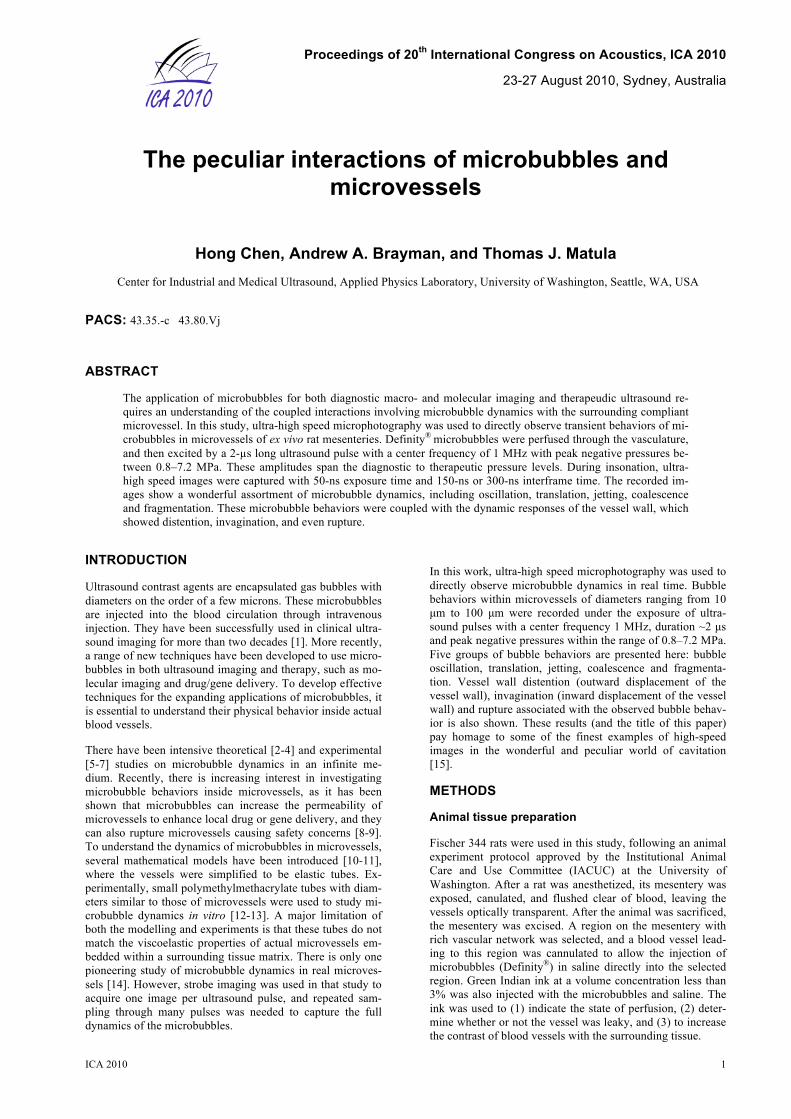
Both symmetrical and asymmetrical bubble oscillations are illustrated in Fig. 2, which consists of frames selected from two high-speed image sequences. In both cases, microbub-bles were exposed to the single pulse shown in Fig. 1b with PNP = 1.5 MPa (the corresponding MI = 1.5, which is within the diagnostic ultrasound exposure level). In both cases, frame 2 shows the microbubble at or near maximum expan-sion.
Fig. 2a illustrates a microbubble in a big microvessel. In this microvessel, the relative location of the microbubble was away from both sides of the vessel wall. The corresponding bubble oscillation was symmetrical (to the extent that we could measure).
The microbubble in Fig. 2b was in a small microvessel. At maximum expansion (1.6 µs), the bubble is distorted along the vessel axis. It’s length in the axial direction was about 25 µm and in the radial direction about 15 µm. The oscillating microbubble caused vessel wall distention (outward move-ment of the vessel wall against the surrounding tissue) at 1.6 µs, and invagination (inward movement into the lumen) at 2.4 µs as pointed out by the two arrows. Relative to its initial state, the vessel diameter measured across the bubble center increased by about 2 µm at 1.6 µs, but decreased by 10 µm at 2.4 µs, indicating that vessel invagination was much larger than distention.
Our observations of bubble distortion along the vessel axis are not limited to this set of images; it is a regular observa-tion. So to is the bias toward vessel invagination. Theoretical models of the coupled interaction between a bubble and a viscoelastic tissue would need to predict both types of behav-ior. Indeed, this may put a restriction on allowed values for elasticity and viscosity.
Figure 2. Typical oscillations of microbubbles in microves-sels. (a) Symmetrical bubble oscillation in a big microvessel: PNP = 1.5 MPa; Vessel diameter = 74 µm; (b) Asymmetrical bubble oscillation in a small microvessel: PNP = 1.5 MPa; Vessel diameter = 20 µm.
Figure 3 illustrates dramatic vessel distention and invagina-tion leading to the rupture of a vessel. The experiment re-corded a cluster of about 4 bubbles inside a vessel of diam-eter 17 µm driven by a pulse with PNP 7.2 MPa. The bubble cluster expanded (0.15 µs) and reached the maximum size at 0.45 µs. Their expansion was somewhat constrained by the vessel wall, as indicated by the elongation of the bubble clus-ter along the axial direction of the vessel. The vessel wall was significantly distended at 0.45 µs. Bubble collapse happened at 1.05 µs leading to nearly axial symmetric vessel invagina-tion. The subsequent re-expansion of several bubble frag-ments outside the vessel at 1.2 µs suggests that the vessel was ruptured. Unlike the other figures, the vessel wall in each frame of this figure was artificially highlighted to show the vessel wall more clearly.

23-27 August 2010, Sydney, Australia Proceedings of 20th International Congress on Acoustics, ICA 2010
ICA 2010 3
Figure 3. Rupture of a microvessel by microbubbles. Micro-bubble induced vessel distention (0.45 µs) and invagination (1.05 µ). The extravasation of the re-expanding bubbles (1.2 µs), indicating that the vessel was ruptured. PNP = 7.2 MPa; Vessel diameter = 17 µm. Zhong, et al. [16] suggested that bubble expansion-induced vessel distention is one of the primary mechanisms contribut-ing to vessel rupture. Figure 3 doesn’t answer this question, as we observe both distention and invagination. Our observa-tions that vessel invagination is greater than distention in a majority of cases of vessels larger than 20 µm in diameter suggests that invagination may play an important role in the rupture of microvessels, especially big microvessels.
Translation
Figure 4 illustrates an example of microbubble translation. The microbubble in Fig. 4a expanded and deformed to an elliptical shape at 1.6 µs, and then collapsed at 3.7 µs. The bubble center translated away from the vessel wall by about 14 µm relative to its initial position, corresponding to an av-erage translational speed of 4.7 m/s. Figure 4b shows the translation of two microbubbles that were originally next to the vessel wall as pointed out by the two arrows in frame 1. The expansion of the two microbubbles caused slight local vessel distention (frame 2). When they collapsed, vessel in-vagination was observed, especially at the location near the lower bubble where a sharp notch-like shape was observed as pointed out by the arrow in frame 3. The two microbubbles then re-expanded nearer the center of the vessel lumen (frame 4). Compared to their initial positions, the upper and lower bubbles translated by 10 µm and 12 µm, respectively. The respective average translation speeds were 11 m/s and 13 m/s.
It has been long recognized that the direction of bubble trans-lation depends on the properties of the nearby boundaries. A bubble oscillating near a rigid surface migrates toward the surface, while a bubble near a free boundary moves away from the boundary. For a bubble near a compliant boundary, it was noted that the rebounding of the boundary after its deformation by the expanding bubble can repel the bubble away from it [17]. In our study, microbubble translation away from the nearby vessel wall was commonly observed when the microbubble was near the vessel wall. The potential ex-planation is that vessel invagination directed flow toward the microbubble, which pushed the microbubble away from the vessel wall. Note that the direction of the ultrasound wave was perpendicular to the imaging plane, and thus the primary radiation force would be directed perpendicular to this plane. As the bubble remained in focus during the imaging, suggests that the primary radiation force did not generate an obvious effect on microbubble translation during this time.
Figure 4 Microbubble translation away from the nearby ves-sel wall. (a) PNP = 4.0 MPa; Vessel diameter = 49 µm; Bub-ble translation =14 µm. (b) PNP = 1.5 MPa; Vessel diameter = 30 µm; Upper bubble translation = 10 µm; Lower bubble translation = 12 µm.
Jetting
Figure 5a shows the formation of a liquid jet due to the inter-action between two microbubbles. At 1.3 µs, a liquid jet was observed penetrating the upper microbubble and directed toward the lower microbubble. The jet was still visible inside the microbubble at 1.6 µs. The length of the jet measured at 1.6 µs was about 29 µm. The lower bound estimate of the liquid jet speed is 48 m/s.
Figure 5b shows the formation of a liquid jet due to the inter-action between a microbubble and the vessel wall. In frame 1, a bubble expanded against the upper vessel wall. A liquid jet was observed directed away from the upper vessel wall in frames 2 and 3. The length of the jet measured at 1.9 µs was about 37 µm. The lower bound estimation of the liquid jet speed was 31 m/s.
Figure 5. Formation of liquid jets in microvessels. (a) PNP = 1.5 MPa; Vessel diameter = 33 µm; (b) PNP = 2.8 MPa; Ves-sel diameter = 47 µm;
In all cases for which the jet direction was clearly identifi-able, the direction of the jet was away from the nearest vessel wall. This is consistent with our observation that a microbub-ble near a vessel wall always translated away from it. There-fore, for larger vessels, liquid jet impingment on the vessel wall may not be the mechanism by which microbubble in-duces rupture, as the direction of the jet is away from the vessel wall. Vessel rutpture by a liquid jet may occur in small microvessels, because a jet directed away from one side of the vessel wall can extend through the bubble and penetrate the other side of the vessel wall.

23-27 August 2010, Sydney, Australia Proceedings of 20th International Congress on Acoustics, ICA 2010
4 ICA 2010
Figure 6 shows the rupture of a small microvessel, where the impact of a liquid jet may contribute to rupture. The diameter of the vessel was about 15 µm and the PNP = 4.0 MPa. The microbubble expanded against both sides of the vessel wall at 1.6 µs, and a liquid jet (pointed out by the arrow) looks to be directed toward the right vessel wall. The length of the jet was about 24 µm, and the speed of the jet was estimated to be 80 m/s, corresponding to a water hammer pressure of about 59 MPa (calculated using where is the fluid density, is the speed of sound in the medium and is the speed of the jet [18]). The microbubble collapsed at 1.9 µs and then re-expanded at 2.5 µs. At 4.0 µs, the bubble is shaped like a mushroom, with the cap outside the vessel and stem (pointed out by the arrow) extending through the vessel wall. In this small microvessel, the microbubble expanded against both sides of the vessel wall, so the direction of the liquid jet may depend on the timing of impact, or on the de-tailed biological structure of the vessel. The water hammer pressure on the vessel wall may be strong enough to rupture such a small microvessel.
Figure 6. Rupture of a microvessel by a microbubble. Liquid jet impact may contribute to the rupture. PNP = 4.0 MPa; Vessel diameter = 15 µm.
Coalescence
In the free field when two bubbles are in close proximity to each other they can coalesce. Figure 7 shows two representa-tive high-speed image sequences that recorded the coales-cence of two bubbles in a big microvessel (Fig. 7a) and a small microvessel (Fig. 7b).
In Fig. 7a we focus on two bubbles highlighted by the arrows in frame 1 within a big microvessel. At 1 µs, they collapsed and each developed a liquid jet toward the other. The two microbubbles re-expanded and coalesced with the liquid jet still visible within the microbubble at 1.3 µs. Then at 2.2 µs, the coalesced bubble collapsed.
Figure 7b shows the coalescence of two bubbles in a small microvessel. The two microbubbles expanded at 1.6 µs, flat-tening against the adjacent bubble surfaces. Their expansion also caused the nearby vessel wall to distend. At 2.4 µs the two bubbles collapsed, and with that, invagination of both sizes of the vessel wall was observed. The one spherical bub-ble recorded at 2.7 µs suggests that the two microbubbles coalesced. The constraining effect of the vessel wall may have facilitated the coalescence of these two microbubbles.
Figure 7. Microbubbles coalescence in microvessels. (a) PNP = 1.5 MPa; Vessel diameter = 52 µm; (b) PNP = 1.5 MPa; Vessel diameter = 29 µm.
Fragmentation
Figure 8 illustrates microbubble fragmentation in a microves-sel. This high-speed image sequence recorded two microbub-bles expanding (1.9 µs), coalescing (2.5 µs), collapsing (3.1 µs and 3.4 µs) and then re-expanding (4 µs) in a vessel of 100 µm in diameter in response to a 7.2 MPa ultrasound pulse. The collapse of the microbubble led to its fragmentation into several small bubbles at 4 µs.
Note that this sequence also recorded the distention and in-vagination of the vessel wall at the location nearest to the microbubbles (the location is pointed out by the arrow in the last frame). The vessel distention is not obvious, but signifi-cant vessel invagination can be observed.
Figure 8. Microbubble fragmentation in a microvessel. PNP = 7.2 MPa; Vessel diameter = 100 µm.
CONCLUSION
In this work, ultra-high speed microphotography was used to study microbubble dynamics in microvessels under the expo-sure of a 2-µs pulse with a center frequency 1 MHz, and a peak negative pressure ranging from 0.8–7.2 MPa. Represen-tative image sequences that show bubble oscillation, transla-tion, jetting, coalescence, and fragmentation were presented, along with corresponding vessel dynamics. The wonderful and peculiar observations point toward understanding the coupled behavior that is important to macro- and molecular ultrasound imaging and therapy applications.
ACKNOWLEDGMENTS
This work was supported in part by NIH grants EB000350, and AR053652.

23-27 August 2010, Sydney, Australia Proceedings of 20th International Congress on Acoustics, ICA 2010
ICA 2010 5
REFERENCES 1 Stride, E.P. & Coussios, C.C. "Cavitation and contrast:
the use of bubbles in ultrasound imaging and therapy". P I Mech Eng H 224, 171-191 (2010).
2 de Jong, N., Cornet, R. & Lancée, C.T. "Higher harmonics of vibrating gas-filled microspheres. Part one: simulations". Ultrasonics 32, 447-453 (1994).
3 Morgan, K.E., et al. "Experimental and theoretical evaluation of microbubble behavior: effect of transmitted phase and bubble size". IEEE Trans Ultrason Ferroelectr Freq Control 47, 1494-1509 (2000).
4 Church, C.C. "The effects of an elastic solid surface layer on the radial pulsations of gas bubbles". J. Acoust. Soc. Am. 97, 1510-1521 (1995).
5 Postema, M., van Wamel, A., Lancée, C.T. & de Jong, N. "Ultrasound-induced encapsulated microbubble phenomena". Ultrasound Med. Biol. 30, 827-840 (2004).
6 Chomas, J.E., et al. "Optical observation of contrast agent destruction". Appl. Phys. Lett. 77, 1056-1058 (2000).
7 de Jong, N., et al. "Optical imaging of contrast agent microbubbles in an ultrasound field with a 100-MHz camera". Ultrasound Med. Biol. 26, 487-492 (2000).
8 Miller, D.L., et al. "Bioeffects considerations for diagnostic ultrasound contrast agents". J. Ultrasound Med. 27, 611-632 (2008).
9 Skyba, D.M., Price, R.J., Linka, A.Z., Skalak, T.C. & Kaul, S. "Direct in vivo visualization of intravascular destruction of microbubbles by ultrasound and its local effects on tissue". Circulation 98, 290-293 (1998).
10 Qin, S.P. & Ferrara, K.W. "Acoustic response of compliable microvessels containing ultrasound contrast agents". Phys. Med. Biol. 51, 5065-5088 (2006).
11 Miao, H., Gracewski, S.M. & Dalecki, D. "Ultrasonic excitation of a bubble inside a deformable tube: Implications for ultrasonically induced hemorrhage". J. Acoust. Soc. Am. 124, 2374-2384 (2008).
12 Zheng, H.R., et al. "Ultrasound-driven microbubble oscillation and translation within small phantom vessels". Ultrasound Med. Biol. 33, 1978-1987 (2007).
13 Caskey, C.F., Kruse, D.E., Dayton, P.A., Kitano, T.K. & Ferrara, K.W. "Microbubble oscillation in tubes with diameters of 12, 25, and 195 microns". Appl. Phys. Lett. 88, - (2006).
14 Caskey, C.F., Stieger, S.M., Qin, S., Dayton, P.A. & Ferrara, K.W. "Direct observations of ultrasound microbubble contrast agent interaction with the microvessel wall". J. Acoust. Soc. Am. 122, 1191-1200 (2007).
15 Lauterborn, W. & Ohl, C.D. "The peculiar dynamics of cavitation bubbles". Appl Sci Res 58, 63-76 (1998).
16 Zhong, P., Zhou, Y.F. & Zhu, S.L. "Dynamics of bubble oscillation in constrained media and mechanisms of vessel rupture in SWL". Ultrasound Med. Biol. 27, 119-134 (2001).
17 Brujan, E.A., Nahen, K., Schmidt, P. & Vogel, A. "Dynamics of laser-induced cavitation bubbles near an elastic boundary". J. Fluid Mech. 433, 251-281 (2001).
18 Prentice, P., Cuschierp, A., Dholakia, K., Prausnitz, M. & Campbell, P. "Membrane disruption by optically controlled microbubble cavitation". Nat. Phys. 1, 107-110 (2005).