The Optimised Sliding Hinge Joint (OSHJ): Design, detail ...
13
Paper 158 NZSEE 2021 Annual Conference The Optimised Sliding Hinge Joint (OSHJ): Design, detail, and implementation in practice S. Ramhormozian Department of Built Environment Engineering, Auckland University of Technology, Auckland. G.C. Clifton Department of Civil and Environmental Engineering, University of Auckland, Auckland. S. Gledhill, M. Muller Beca Ltd. New Zealand ABSTRACT The Optimised Sliding Hinge Joint (OSHJ) is a low-damage, resilient, versatile, and cost effective seismic resisting system developed primarily for Moment Resisting Steel Framed (MRSF) buildings. The OSHJ is the optimized version of the Sliding Hinge Joint (SHJ) with Asymmetric Friction Connections (AFCs). The OSHJ is an accurate and precise system that imposes no damage on the structural members (e.g. beams and columns) during a severe seismic event, dissipates large amount of severe earthquake induced energy through friction in the AFCs, exhibits dynamic self‐ centering of the building, and retains over 90% of the initial strength and stiffness of the system following a severe seismic event and over the life time of the building with no need to inspect, retighten, or replace the friction sliding components. To achieve this, one of the key components introduced in the OSHJ are the partially deflected Belleville Springs (BeSs) which must be appropriately designed, manufactured, and installed to fit the purpose. This paper presents an explanation on the SHJ seismic behaviour as well as the advantages of the OSHJ in addition to those of the SHJ. The design, detail, and installation approaches of the OSHJ are also briefly outlined. Finally, application of the OSHJ in three resilient multi-storey buildings is covered. 1 INTRODUCTION Moment resisting frames (MRFs) are one of the most commonly used lateral force resisting systems for steel buildings. Steel MRFs typically consist of a simple, rectangular arrangement of beams and columns, with the
Transcript of The Optimised Sliding Hinge Joint (OSHJ): Design, detail ...

Paper 158
NZSEE 2021 Annual Conference
The Optimised Sliding Hinge Joint (OSHJ): Design, detail, and implementation in practice S. Ramhormozian Department of Built Environment Engineering, Auckland University of Technology, Auckland.
G.C. Clifton Department of Civil and Environmental Engineering, University of Auckland, Auckland.
S. Gledhill, M. Muller Beca Ltd. New Zealand
ABSTRACT The Optimised Sliding Hinge Joint (OSHJ) is a low-damage, resilient, versatile, and cost effective seismic resisting system developed primarily for Moment Resisting Steel Framed (MRSF) buildings. The OSHJ is the optimized version of the Sliding Hinge Joint (SHJ) with Asymmetric Friction Connections (AFCs). The OSHJ is an accurate and precise system that imposes no damage on the structural members (e.g. beams and columns) during a severe seismic event, dissipates large amount of severe earthquake induced energy through friction in the AFCs, exhibits dynamic self‐centering of the building, and retains over 90% of the initial strength and stiffness of the system following a severe seismic event and over the life time of the building with no need to inspect, retighten, or replace the friction sliding components. To achieve this, one of the key components introduced in the OSHJ are the partially deflected Belleville Springs (BeSs) which must be appropriately designed, manufactured, and installed to fit the purpose.
This paper presents an explanation on the SHJ seismic behaviour as well as the advantages of the OSHJ in addition to those of the SHJ. The design, detail, and installation approaches of the OSHJ are also briefly outlined. Finally, application of the OSHJ in three resilient multi-storey buildings is covered.
1 INTRODUCTION Moment resisting frames (MRFs) are one of the most commonly used lateral force resisting systems for steel buildings. Steel MRFs typically consist of a simple, rectangular arrangement of beams and columns, with the

Paper 158 – The Optimised Sliding Hinge Joint (OSHJ): Design, detail, and implementation in practice
NZSEE 2021 Annual Conference
beams rigidly connected to the columns to permit transfer of moment. MRFs resist lateral loads through rigid frame action, principally by the development of bending moment and shear force in the beams and columns. They allow maximum use of building space for the client. The experience of the 1994 Northridge Earthquake, followed by a similar experience in the 1995 Kobe Earthquake, showed a basic shortcoming in the traditional rigid beam-to-column connections in steel MRFs (Engelhardt 2001) and led to the development of procedures to avoid weld failure in steel connections. These methods, such as the reduced beam section and bolted flange plate connections (Roeder 2002) are typically based on capacity design principles, where energy is dissipated through controlled damage in predefined plastic hinge locations, without influencing the rest of the structural elements of the capacity-designed structural system. Despite being effective in providing safety and preventing collapse, such design based systems are usually associated with irrecoverable plastic deformation in the beams or joints. This can cause large economic losses both in the post-disaster repair and downtime due to closure of the building (Khoo 2013, Ramhormozian 2018). Additionally, because strength and stiffness are coupled in a rigid jointed MRF and the stiffness, which is related to and controls the deformations, is often the governing factor for beam size selection, the frames can end up stronger than desired, which in turn puts large actions into the columns and foundation system, requiring increased costs of construction to avoid the risk of failures in the foundations. These issues were a driver behind further developments undertaken by the researchers to develop low damage seismic solutions that decoupled strength and stiffness in MRFs.
The low damage design philosophy of structures aims to make the structure occupiable immediately after an ultimate limit state (ULS) event and potentially occupiable in a short time-frame after an event larger than the ULS (MacRae and Clifton 2013). A number of low damage solutions for steel MRFs have been developed, most of which involve making the beam to column connections semi-rigid with the earthquake-induced rotation being accommodated within the connection. Such systems include Rotational Slotted Bolted Connection using the symmetric friction connection (Yang and Popov 1995), post-tensioned steel tendon systems (Danner and Clifton 1995), shape memory alloy systems (Fugazza 2005), and the Sliding Hinge Joint (SHJ) connection using the Asymmetric Friction Connection (AFC) (Clifton 2005) to minimise permanent deformation and/or residual drifts in buildings resulting from severe earthquake shaking. Low damage steel MRFs actually involve beam end connections providing nonlinear resistance that dissipate energy with negligible damage, while the structural members remain elastic. Beam stiffness and connection strength are decoupled meaning beams can be made stiffer to control lateral deflections without increasing the overstrength actions going into the columns. It is worth noting that the above mentioned low damage solutions other than the SHJ for the MRFs have been either costly and complex and/or require further developments to be practically implemented.
2 SLIDING HINGE JOINT (SHJ) The sliding hinge joint (SHJ) (Clifton 2005) with asymmetric friction connections (AFCs) is a low damage beam-column connection developed for seismic MRSFs. Figure 1 shows typical layout of the SHJ. AFC is a type of slotted bolted connection (SBC) acting as fuse for the SHJ. AFCs are the friction energy dissipating components and are designed to slide at a pre-determined sliding force, under severe earthquake, to dissipate input energy by friction and to limit the maximum beam end bending moment to a pre-determined level, hence effectively preventing any over-loading induced damage to the SHJ beam and column (note the slotted holes in the bottom flange plate as well as web bottom bolts level of web plate allowing such sliding to occur). Being subjected to an event larger than the ULS event, the SHJ may undergo large beam-column relative rotation through sliding in two AFCs which are located at the beam web bottom bolt and bottom flange levels. No lateral movement occurs between the beam and column at top flange level through an axially stiff, rotationally flexible detail. For the events smaller than the ULS, the SHJ is intended to remain rigid. At the end of an earthquake which is larger than the ULS earthquake, the SHJ is ideally intended to

Paper 158 – The Optimised Sliding Hinge Joint (OSHJ): Design, detail, and implementation in practice
NZSEE 2021 Annual Conference
come back to its as-built condition. This necessitates the SHJ to dynamically self-centre and to retain its as built AFCs’ sliding strength through retaining the AFCs’ clamping force. This ideal performance has been achieved after developing the Optimised Sliding Hinge Joint (OSHJ) as is explained in this paper.
Figure 1: Sliding Hinge Joint Side Elevation (Not to Scale) (MacRae, Clifton et al. 2010)
The AFC consists of five plies, including the beam bottom flange or web, bottom flange plate (cleat) or web plate, cap plate, and two shims at both sides of the bottom flange or web plates, all clamped by the pre tensioned high strength friction grip (HSFG) structural bolts. The AFC has two main sliding surfaces at both sides of the cleat. When the applied force overcomes the frictional resistance of the first sliding surface, i.e. the cleat and the upper shim interface, this surface starts to slide (i.e. the cleat moves relative to the beam bottom flange), while the cap plate remains fixed relative to the cleat and moves relative to the beam bottom flange. After a short time or distance of movement along the first sliding surface, the cap plate starts to become fixed in position relative to the beam bottom flange. From this point onwards for that direction of displacement, the cleat slides between two sliding surfaces (i.e. upper and lower shims), which almost doubles the sliding shear resistance (called the stable sliding shear resistance) developed by the AFC. At this stage, the bolts are deformed into the double curvature state. Following load removal and then load reversal, the sliding occurs on the first interface followed by the second interface pushing the bolts again into double curvature in the opposite direction. This provides the AFC with a “pinched” hysteretic behaviour, requiring less work to be done (or energy to be spent) to recover all of the travelled displacement compared with a rectangular typical hysteretic behaviour. This provides the SHJ with an inherent dynamic self-centring capability, which is desirable.
3 IMPROVEMENTS TO DEVELOP OPTIMISED SHJ (OSHJ) AND AVAILABLE DESIGN GUIDE
Due to a number of conditions, the SHJ could not satisfy all of its ideal performance definitions. These are briefly outlined below and are the main drivers behind developing the OSHJ.
• The AFCs, as the SHJ’s key energy dissipating components, were subject to a considerable post-sliding clamping force reduction because of the following reasons: - The bending moment, shear force , and axial load (MVP) interaction in the bolt body during stable
sliding state (Ramhormozian, Clifton et al. 2017, Ramhormozian, Clifton et al. 2019) may further yield the bolt material causing the post-sliding bolt tension to drop. It is worth noting that the bolts are traditionally tensioned into the post yield condition at installation in practice, using part-turn method of tightening according to NZS3404 (1997/2001/2007), making this clamping force

Paper 158 – The Optimised Sliding Hinge Joint (OSHJ): Design, detail, and implementation in practice
NZSEE 2021 Annual Conference
reduction inevitable. Hence tightening the AFC bolts on installation only into the elastic range seemed a desirable solution.
- The prying effect at the SHJ beam bottom flange level under large beam-column relative rotation may impose an additional axial plastic strain on the AFC bolts causing the post-sliding bolt tension to reduce.
- Wearing of the sliding surfaces may reduce the total thickness of the AFC plies per bolt, resulting in the bolt tension reduction.
- AFC bolts may rub against sides of the cleat elongated holes. This may reduce the AFC bolts’ integrity, causing a bolt tension drop.
- Vibration induced self-loosening, joint creep, and bolt relaxation are amongst the common bolt tension loss reasons that may be considered for any bolted connection amongst which the AFC may not be an exception, although this is very unlikely to occur in these joints in buildings
• The optimum sliding components material and surface preparations of the sliding surfaces had to be researched and identified. This was to identify an optimum yet common material type and surface preparation level to be recommended in practice associated with a consistent and accurate coefficient of friction as well as minimum degradation of the sliding surfaces and clamping force.
• An accurate, precise, reliable, and versatile bolt tightening method in the elastic, and not plastic, range of the bolt tension was needed to be developed so that at the time of installation the delivered clamping force could be accurately what the designer has identified.
• The optimum level of bolt tension in the elastic range needed to be researched and identified to exhibit an optimum seismic performance with minimum degradation and clamping force loss.
• Retaining the design bolt tension as well as minimizing its variability both over the life time of the building and during as well as following a severe seismic induced sliding was needed.
• Using Belleville springs (BeSs), a conical washer type spring (see figure 2), was the best initial option considered as a remedy to the bolt tension loss. However this had to be researched and the way of designing and installing them to fit the purpose, had to be developed. Moreover, a potential disadvantage of retaining the post sliding AFC clamping force could have been reducing the self-centring capability of the system through exhibiting resistance to slide while the system tends to come back to its original position. This issue had to be researched and addressed too.
All of the abovementioned challenges were researched, and overcome through detailed analytical, numerical, and extensive experimental research to develop the Optimised Sliding Hinge Joint (OSHJ). Figure 2 shows the OSHJ layout from different angles. Note that the BeSs and shims are shown in red colour.

Paper 158 – The Optimised Sliding Hinge Joint (OSHJ): Design, detail, and implementation in practice
NZSEE 2021 Annual Conference
Figure 2: 3D Elevations of the Optimised Sliding Hinge Joint (OSHJ) (Not to Scale) (Ramhormozian and Clifton 2020)
The first comprehensive article on the design and detailing provisions and design example for the traditional SHJ was published as a HERA report, i.e. HERA Steel Design & Construction Bulletin (DCB) No. 68, in 2002 (Clifton, Butterworth et al. 2002). This explains a background to the SHJ developments, performance of the SHJ and its design philosophy, design and detailing of the SHJ, design of the MRSFs incorporating the SHJ, and SHJ design example. A more detailed and comprehensive version of this article, as a PhD thesis on the SHJ and other seismic resisting systems developments, was published in 2005 (Clifton 2005). The outcome of the research and practical applications has led to modifications of the original design procedure and detailing requirements published in 2007 (Clifton 2007). In 2009 Steel Construction New Zealand (SCNZ) published a design example of the SHJ (Cowie 2009) which is adopted from (Clifton 2005). Finally in 2020 a design and installation guide was published by Heavy Engineering Research Association (HERA) (Ramhormozian and Clifton 2020) which supersedes the abovementioned guides and needs to be followed in

Paper 158 – The Optimised Sliding Hinge Joint (OSHJ): Design, detail, and implementation in practice
NZSEE 2021 Annual Conference
any use of the OSHJ given the optimised performance. The key modifications implemented to develop the OSHJ and included in (Ramhormozian and Clifton 2020) are as follows:
• Material selection of the shims; • Surface preparation of the sliding surfaces; • Coefficient of friction to be used; • Allowable range of the AFCs installed bolt tension in the elastic range; • Sliding shear capacity calculation incorporating modified bolt model, modified strength reduction factor,
and modified overstrength factor; • Design and use of the Belleville Springs (BeSs) as necessary components; • Method of checking and tightening the bolts in the elastic range with BeSs; • Occasional changes in detailing and dimensions; • Philosophy and approach of considering ULS winds and earthquakes.
4 MODELLING, LOADING, ANALYSIS, AND DESIGN OF THE MRF WITH OSHJ The modelling is undertaken using the same approach as followed for the traditional MRF, i.e. the MRF beam-column connections are defined as moment (rigid) connections and the analysis is undertaken on this basis under any desired load combination. The column base is recommended to be a conventional rigid column base with nominal stiffness of 1.67(EI/L)column designed and detailed according to (NZS3404 1997/2001/2007). If the designer requires, based on a special need and design for a special project, to use pinned or semi-rigid (e.g. friction based) column base detail, that may also be considered.
The seismic actions are calculated same as the traditional approach for the MRFs using equivalent static (ESM) or Modal Response Spectrum (MSA) Methods where is allowed by NZS1170.5:2004 (2004). As for the ductility factor, the OSHJ is reliably able to accommodate very high ductility demand up to 4, which is the value given in NZS1170.5:2004 (2004) at which the strength requirements for the ULS limit state are the same as those for the SLS limit state. Designing for higher ductility levels will result in inelastic demand at the SLS which is not recommended for building functionality and appearance after a moderate level (SLS intensity) earthquake. Hence, the designer has full flexibility to choose the appropriate ductility based on the project’s requirements and deflection checks.
As for the design lateral load, it is required to check for the ULS design moment from earthquake (which includes the reduction from the elastic load due to ductility) and the ULS design moment from wind and only use the greater of the two as the design moment for the OSHJ. Note that softening of the traditional SHJ after sliding which made the structure more vulnerable to wind induced deflection is no longer the case with the OSHJ. The OSHJ itself is then sized to resist only the maximum of ULS design moment from earthquake and wind with ignoring joint moments induced by gravity only. The design shear force is the maximum of two shear forces namely (design shear force from permanent and imposed load for use in conjunction with earthquake + design shear force derived from out-of-balance design lateral load resulted (earthquake or wind whichever is larger) moments acting on the clear beam length) and (design shear force for full factored permanent and imposed load).
The beam is sized to develop a moment capacity being able to resist the maximum moment from applied vertical loading in a simply supported manner, and then checked for providing adequate frame stiffness. If the beam size, and consequently stiffness, is required to be increased, the moment input through the joint into the column does not have to increase accordingly. This is a major simplification in design and versatility in selecting the beam size offered by the OSHJ compared with the traditional MRFs. The columns are then designed to resist the overstrength action developed by the joint, not that from the beam. This means the

Paper 158 – The Optimised Sliding Hinge Joint (OSHJ): Design, detail, and implementation in practice
NZSEE 2021 Annual Conference
beam depth can be chosen for gravity strength and lateral stiffness control without impacting on the column design.
5 WORLD FIRST PROJECT APPLICATION OF AN OPTIMISED SLIDING HINGE JOINT (OSHJ) – A CASE STUDY
The OSHJ is being implemented for the first time in the new $50 million office building precinct designed by Beca structural engineers. The development for Waikato Tainui is known as Project Hauata and is located on the corner of Collingwood and Tristram Streets in central Hamilton. This world first deployment of the OSHJ will occur later in 2021 when the steel framed office building precinct is erected, and the joints installed and tightened. The new building complex has been conceived to house 650 staff. As an Importance level 2 building (IL2), the design brief does not require specific post disaster to repair and reoccupy. However, like all building owners taking a long-term strategic view, Waikato Tainui’s selection of a resilient low damage structure was an obvious choice.
Its design consists of three seismically separate structures with link bridges between, forming two atrium areas. The large connected floor plates each accommodate ground level and three suspended office floors with a roof top plate deck plant.
The new technology within the building will not only help protect the investment for Iwi and generations to come but also reduces anchor tenant ACC’s exposure to the disruptive effects and downtime caused by seismic damage. The choice of structural connections and systems has been selected to improve post event seismic performance. Figure 3 shows 3D View of the buildings.
Figure 3: 3D View of the Project Hauata - TGH and ACC Collingwood Development
5.1 Selected Structural Systems
In the longitudinal direction, each of the three building structures lateral load resisting systems consist of four concentrically braced frames (CBF’s) equipped with Buckling Restrained Braces (BRB’s) arranged in an inverted chevron configuration.
In the transverse direction, each building is braced by steel moment resisting frames (MRF’s) on all primary gridlines. The MRFs beam to column joints are each equipped with OSHJs to form the MRF beams to Circular Hollow Section (CHS) column connections.

Paper 158 – The Optimised Sliding Hinge Joint (OSHJ): Design, detail, and implementation in practice
NZSEE 2021 Annual Conference
The foundations for the three buildings consist of a reinforced concrete beam grillage system, supported by cast-in-place bored concrete piles located concentrically under each CHS column.
Figures 4 and 5 show typical elevations of the longitudinal and transverse lateral bracing configurations.
Figure 4: Typical longitudinal elevation
Figure 5: Typical transverse elevation
Paper 158 – The Optimised Sliding Hinge Joint (OSHJ): Design, detail, and implementation in practice
NZSEE 2021 Annual Conference
5.2 OSHJ Connection Design Basis
The OSHJ connection has been designed based on a ductility of μ = 3.0 and the MRF frames have been designed for the overstrength actions of the OSHJs. In this manner the joints are the ductile element (i.e. fuse), precluding damage to the beams and the columns.
All OSHJ have been designed to behave in a rigid manner under normal SLS seismic loading but to allow rotation of the columns relative to the beams through controlled friction sliding in a ULS seismic event. The OSHJs (web and bottom flange bolts) were all detailed with Belleville springs (BeSs), which were carefully designed and detailed to maintain the MRFs’ strength and stiffness as well as to enhance the self-centering tendency of the building post-earthquake. Hence, the OSHJ will provide, compare to the SHJ, a more dependable, resilient connection, with reduced degradation in bolt tensions which reduces the need to replace or re-tension bolts following an earthquake.
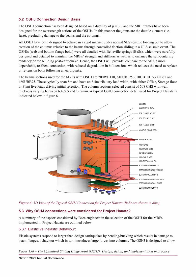
The beams sections used for the MRFs with OSHJ are 700WB130, 610UB125, 610UB101, 530UB82 and 460UBB75. These typically span 8m and have an 8.4m tributary load width, with either Office, Storage floor or Plant live loads driving initial selection. The column sections selected consist of 508 CHS with wall thickness varying between 6.4, 9.5 and 12.7mm. A typical OSHJ connection detail used for Project Hauata is indicated below in figure 6.
Figure 6: 3D View of the Typical OSHJ Connection for Project Hauata (BeSs are shown in blue)
5.3 Why OSHJ connections were considered for Project Hauata?
A summary of the aspects considered by Beca engineers in the selection of the OSHJ for the MRFs implemented in Project Hauata are outlined below.
5.3.1 Elastic vs Inelastic Behaviour:
Elastic systems respond to larger than design earthquakes by bending/buckling which results in damage to beam flanges, behaviour which in turn introduces large forces into columns. The OSHJ is designed to allow

Paper 158 – The Optimised Sliding Hinge Joint (OSHJ): Design, detail, and implementation in practice
NZSEE 2021 Annual Conference
inelastic rotation between the beam and column to occur when the design ULS earthquake moment is exceeded. The ultimate level earthquake rotation is expected to be accommodated within the slotted holes.
5.3.2 Decoupling stiffness and strength:
One of the advantages the OSHJ offers over conventional rigid-jointed MRF systems is the ability to decouple seismic and gravity requirements in the frame and connection design. The beam depth can be chosen for gravity strength and lateral stiffness control without impacting on the column design.
5.3.3 Consideration of Alternatives:
Other alternatives such as elastic, ductile/damage prone systems and low damage beam end connections were explored during the concept design stage of Project Hauata. The OSHJ offered the best performance and was of comparable construction and cost to traditional welded/bolted moment end plates. This connection has proven through design and testing to offer resilient building performance at a cost comparable to traditional ductile and damage prone systems.
5.3.4 Key desirable features considered:
• The OSHJ dissipates seismic energy through friction sliding, transferring that energy to thermal and sound energises. The joint has a stable hysteric response, with enhanced dynamic recentring promoted by the well designed, detailed, and partially deflected Belleville springs.
• The OSHJ is a semi rigid joint which during service keeps the building rigid but in response to large earthquakes it slides and allows the rotation of the column relative to the beam.
• Beam and columns are protected from seismic damage, the OSHJ is the weakest element in the MRF system.
• The OSHJ dynamically self-centres and returns to the rigid state when earthquake stops, assisting in restoring the building structure to the initial state before the seismic event.
• The use of OSHJ in MRFs helps reduce column and foundation forces.
5.4 Lessons learnt in the design and specification of the OSHJ
5.4.1 Design:
From the design point of view, the process is relatively straight forward. The design engineer is recommended to read all precedent literature on the sliding hinge joint (SHJ) and then review the design guideline on the OSHJ now published by HERA.
All the MRF beams are designed in first instance to resist the maximum applied gravity loads (i.e. dead “permanent” and live “imposed” loads) in a simply supported condition. This is followed by the design of OSHJs, which are sized to resist only the moment generated by the earthquake actions for the chosen ductility (e.g. μ=3 for Project Hauata). Overstrength and other variables are considered such that the final joint strength is sufficiently weaker than the selected beam section and column, ensuring a weak beam-strong column system where the joint itself forms the ductile low damage fuse. The main MRF columns and beam elements and connecting flange plates are designed to resist the overstrength actions developed by the joint, not those from the beams (the OSHJ overstrength factor and the stable sliding force reduction factor are presented in (Ramhormozian and Clifton 2020)).
In Project Hauata as the CHS column was part of two lateral systems, careful classification and selection of the columns for stability and buckling is required as is ensuring they behave within acceptable rotation limit ranges. Hence undertaking a bi-directional pushover was required to demonstrate hinge formation in the column base section does not occur during ULS earthquakes. A key lesson for future projects maybe to preferably avoid the use the MRFs with OSHJs as part of a bi directional system, and utilise them within uni-

Paper 158 – The Optimised Sliding Hinge Joint (OSHJ): Design, detail, and implementation in practice
NZSEE 2021 Annual Conference
directional systems, however that will depend on client and architectural requirements and this project shows that the OSHJ system can be effectively used with concurrent columns.
The design process for the OSHJs results in a system that can be easily tuned to match the seismic demands and hence when compared to other ductile/damage prone system allows the designer an ability to refine and tune system strength and reduce the overstrength actions on MRF primary elements and foundations. This can be achieved not only by adjusting the diameter and number of bolts on the bottom flange and web bottom connections but also by modifying the installed bolt tension load within the allowable range presented in (Ramhormozian and Clifton 2020). Additional checks are required to confirm that each selected OSHJ remains rigid and no AFC sliding occurs under SLS lateral loads due to earthquake and wind actions.
Solon Manufacturing Co. based in the USA are a leading and reputable BeSs supplier and can provide product specifications and load deflection curves required for the design.
All the design calculations can be easily automated using spreadsheets to expedite both the analysis and the joint configuration selection. The results can be displayed in a summary table with all relevant information required for fabrication as well as for installation, including the dimensions, the size and number of bolts, the type of BeSs and required installed bolt tension.
5.4.2 Detailing:
The use of OSHJ enables a special CHS to UB connection which consists of collar transfer plates bolted to the beam flanges. High hardness (abrasion resistant) steel shims are used between collar transfer plates and beam flanges and cap plates, similarly for the web connections. The collar transfer plate thickness typically varies between 16mm and 20mm, depending on the selected bolt diameter. Standard grade 8.8 bolts are used (typically M16 and M20 bolts). The BeSs are required for all sliding components of the OSHJ and are factory pre-set (see (Ramhormozian, Clifton et al. 2017) for more information) to achieve full elastic behaviour.
Detailing of the connections using all of the above features require special attention and could result in a complex task, in particular when CHS columns are used, as the web cleat is connected to the face of the column and the flange transfer plates surround the column to convey the overstrength forces. It is important to check not only that the column, transfer plates and welds can resist these actions, but also that there is sufficient room around the perimeter columns for the transfer plates (i.e. slab edge distance dictates the transfer plate width).
The gap provided between the column web cleat edge and the beam web edge, as well as the bottom flange and web bottom slotted holes, must always remain clear and unobstructed for the joint to slide in a seismic event. Care is required in the design and detailing of Secondary steel structures and non-structural fixings. The engineer should endeavour to ensure these elements do not prevent the OSHJ from sliding (such as locking up the beam bottom flange at column junctions which can inadvertently occur around the structures perimeter/façade locations.
Furthermore, for structures with MRFs in both orthogonal directions it is advisable to use the same beam depth to limit the number of collar transfer plates to two per column. If the beams have the same top flange alignment but are not the same depth, a second bottom transfer collar plate is necessary and special detailing is required to avoid impeding the seismic gap of the largest beam.
5.4.3 Installation:
With regards to the installation and tightening process for the bolts in the OSHJ, it is essential that the installation sequence is well understood by the steel fabricators and erectors. A robust quality assurance methodology is required to control the amount of rotation is applied to each of the sliding component bolts. A summary of the key aspects of the installation and tightening procedure is noted below.

Paper 158 – The Optimised Sliding Hinge Joint (OSHJ): Design, detail, and implementation in practice
NZSEE 2021 Annual Conference
Top flange and web top bolts: installed with a hardened washer under the component to be turned. These bolts are snug tightened in the normal way, working from the column outwards.
Bottom flange and web bottom bolts (sliding component bolts): installed with a BeS located under the bolt head and a BeS under the nut. The purpose of these BeS is to provide a washer that maintains bolt tension under cyclic loading and to enhance the dynamic self-centering capability. First, these bolts are snug tightened working from the column outwards and the nut is rotated by the amount necessary to fully compress the two BeSs. It is important that the bolt does not rotate when this is being done and that the plies achieve full contact at the bolt lines, i.e. with no visible gap. Secondly, these bolts are loosened one by one (until the BeSs can move), each nut is then finger tightened and turned to the specified amount of rotation turn to achieve the target installed bolt tension. In this case the bolts are tightened working back in towards the column.
6 CONCLUSION This paper provides a background of the developments on the seismic resisting Moment Resisting Frames (MRFs) followed by explaining the seismic behaviour and characteristics of the Sliding Hinge Joint (SHJ), a low damage alternative for the traditional ductile MRF beam-column connection. The recent research programmes resulted in developing the Optimise Sliding Hinge Joint (OSHJ) as well as the advantages and key design and installation considerations of the OSHJ compared with those of the SHJ are also outlined. Finally, world first application of the OSHJ in three resilient multi-storey office buildings, Project Hauata - Tainui Group Holdings (TGH) and Accident Compensation Corporation (ACC) Waikato Tainui development, is covered.
7 REFERENCES Clifton, C. (2007). Sliding Hinge Joint: Revisions to the Design Procedure. NZ Heavy Research Engineering Assn (Inc),
Manukau City.
Clifton, G. C. (2005). Semi-rigid joints for moment-resisting steel framed seismic-resisting systems. PhD, University of Auckland.
Clifton, G. C., J. Butterworth and T. Miller (2002). The Sliding Hinge Joint: Design and Detailing Provisions and Design Example. HERA Steel Design & Construction Bulletin.
Cowie, K. (2009). "Semi-rigid Sliding Hinge Joint." Steel Construction New Zealand.
Danner, M. and G. C. Clifton (1995). Development of moment-resisting steel frames incorporating semi-rigid elastic joints. Manukau City, New Zealand, Heavy Engineering Research Association (HERA).
Engelhardt, M. D. (2001). Ductile Detailing of Steel Moment Frames: Basic Concepts, Recent Developments and Unresolved Issues. XIII Mexican Conference on Earthquake Engineering. Guadalajara, Mexico.
Fugazza, D. (2005). Use of Shape-Memory Alloy Devices in Earthquake Engineering: Mechanical Properties, Advanced Constitutive Modelling and Structural Applications. PhD, Universit`a degli Studi di Pavia.
Khoo, H. H. (2013). Development of the low damage self-centering Sliding Hinge Joint. PhD, University of Auckland.
MacRae, G. and C. Clifton (2013). Low Damage Design of Steel Structures. Steel Innovations 2013 Workshop, Christchurch, New Zealand, Steel Construction New Zealand.
MacRae, G. A., G. C. Clifton, H. Mackinven, N. Mago, J. Butterworth and S. Pampanin (2010). "The Sliding Hinge Joint Moment Connection." Bulletin of the New Zealand Society for Earthquake Engineering 43(3): 202.
NZS1170.5:2004 (2004). Structural Design Actions - Part 5: Earthquake design actions. New Zealand, Standards New Zealand.
NZS3404 (1997/2001/2007). Steel structures standard, incorporating Amendments 1 and 2, Wellington [N.Z.]: Standards New Zealand.
Ramhormozian, S. (2018). Enhancement of the Sliding Hinge Joint Connection with Belleville Springs. PhD, University of Auckland.

Paper 158 – The Optimised Sliding Hinge Joint (OSHJ): Design, detail, and implementation in practice
NZSEE 2021 Annual Conference
Ramhormozian, S. and G. C. Clifton (2020). Optimised Sliding Hinge Joint (OSHJ): Design and Installation Guide for a Low Damage Seismic Resisting System - R4-155. Heavy Engineering Research Association (HERA), Auckland, New Zealand.
Ramhormozian, S., G. C. Clifton, G. A. MacRae and G. P. Davet (2017). "Stiffness-based approach for Belleville springs use in friction sliding structural connections." Journal of Constructional Steel Research 138(Supplement C): 340-356.
Ramhormozian, S., G. C. Clifton, G. A. MacRae, G. P. Davet and H.-H. Khoo (2019). "Experimental studies on Belleville springs use in the sliding hinge joint connection." Journal of Constructional Steel Research 159: 81-94.
Roeder, C. (2002). "Connection Performance for Seismic Design of Steel Moment Frames." Journal of Structural Engineering 128(4): 517-525.
Yang, T.-S. and E. P. Popov (1995). Experimental and Analytical Studies of Steel Connections and Energy Dissipators. Berkeley, University of California, Earthquake Engineering Research Center.