The Network Layer CT542. Content Network Layer Functions ( Context of the operation of network layer...
68
The Network Layer CT542
-
Upload
alicia-cook -
Category
Documents
-
view
246 -
download
1
Transcript of The Network Layer CT542. Content Network Layer Functions ( Context of the operation of network layer...
The Network Layer
CT542
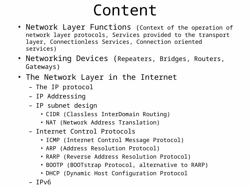
Content• Network Layer Functions (Context of the operation of network layer
protocols, Services provided to the transport layer, Connectionless Services, Connection oriented services)
• Networking Devices (Repeaters, Bridges, Routers, Gateways)
• The Network Layer in the Internet– The IP protocol
– IP Addressing
– IP subnet design• CIDR (Classless InterDomain Routing)
• NAT (Network Address Translation)
– Internet Control Protocols• ICMP (Internet Control Message Protocol)
• ARP (Address Resolution Protocol)
• RARP (Reverse Address Resolution Protocol)
• BOOTP (BOOTstrap Protocol, alternative to RARP)
• DHCP (Dynamic Host Configuration Protocol
– IPv6
Network layer• It is the lowest layer that deals with end-to-end transmission• Concerned with getting packets from the source all the way
to the destination• Should know about the topology of the communication
subnet and choose appropriate paths through it• It should choose routes to avoid overloading some of the
communication lines and routers while leaving others idle• When source and destination are in different networks, new
problems occur…it is up to this layer to deal with them
Network layer
• An interface between the transport layer and the
data link/physical layer:
– services should be independent of the router technology
• must be able to communicate across all types of network
– transport layer should not know about the subnet
structure, number, type and topology of the routers
present
– The network address made available to the transport
layer should use a uniform numbering plan, even across
LANs and WANs
Network layer
• Decide between:• connectionless service – strong support by Internet community
argues that the network layer should just move packets around
and nothing more; the network service should be connectionless
with primitives SEND_PACKET and RECEIVE_PACKET; no
packet ordering nor flow control should be performed, since
hosts are going to do it anyway (Internet)
• connection orientated – strong support in the telephone
companies argue that network should provide reliable,
connection oriented services; they saying that quality of service
is the dominant factor, and without connections in subnet, it is
very difficult to achieve it (ATM)
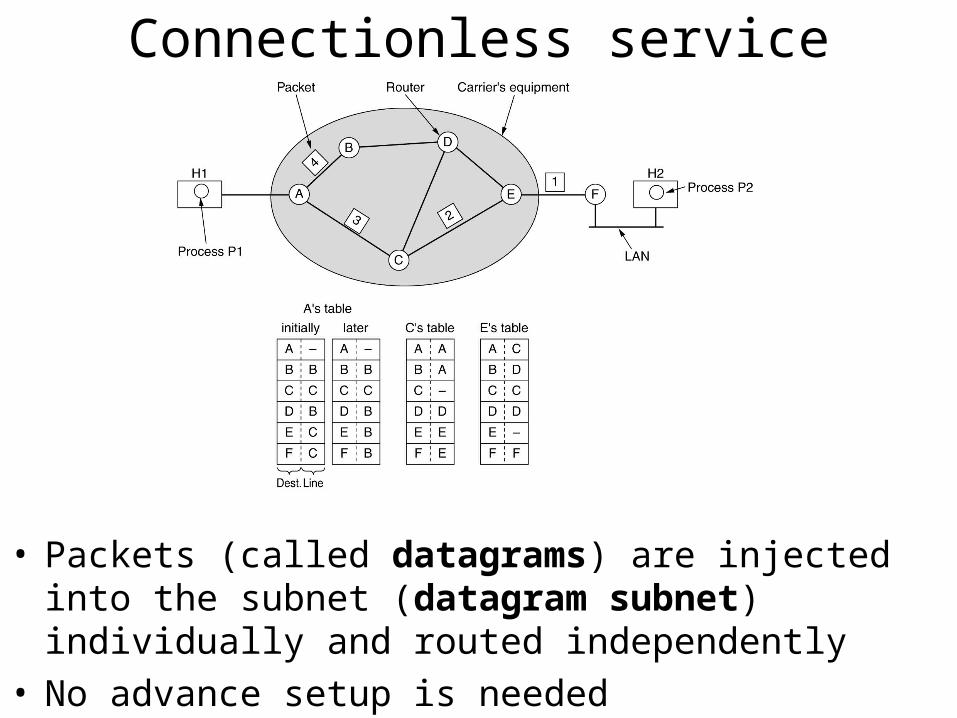
Connectionless service
• Packets (called datagrams) are injected into the subnet (datagram subnet) individually and routed independently
• No advance setup is needed
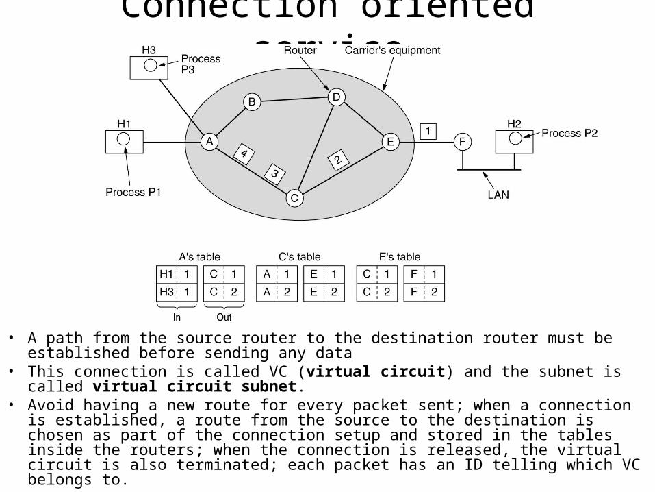
Connection oriented service
• A path from the source router to the destination router must be established before sending any data
• This connection is called VC (virtual circuit) and the subnet is called virtual circuit subnet.
• Avoid having a new route for every packet sent; when a connection is established, a route from the source to the destination is chosen as part of the connection setup and stored in the tables inside the routers; when the connection is released, the virtual circuit is also terminated; each packet has an ID telling which VC belongs to.
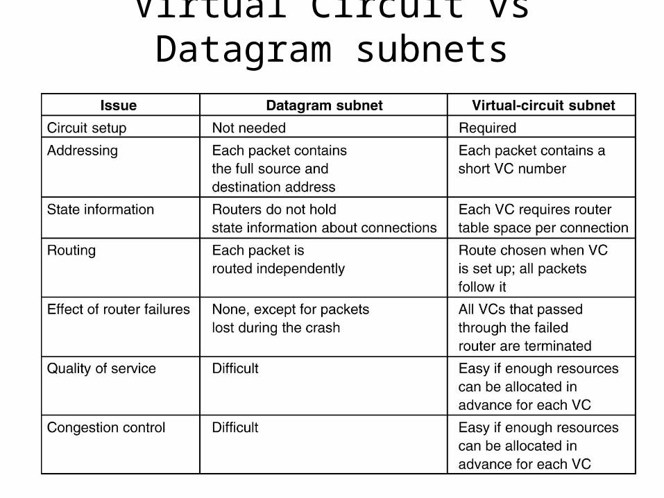
Virtual Circuit vs Datagram subnets
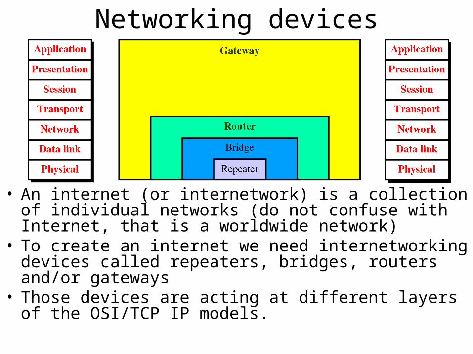
Networking devices
• An internet (or internetwork) is a collection of individual networks (do not confuse with Internet, that is a worldwide network)
• To create an internet we need internetworking devices called repeaters, bridges, routers and/or gateways
• Those devices are acting at different layers of the OSI/TCP IP models.
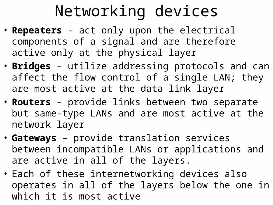
Networking devices• Repeaters – act only upon the electrical components of a
signal and are therefore active only at the physical layer• Bridges – utilize addressing protocols and can affect the
flow control of a single LAN; they are most active at the data link layer
• Routers – provide links between two separate but same-type LANs and are most active at the network layer
• Gateways – provide translation services between incompatible LANs or applications and are active in all of the layers.
• Each of these internetworking devices also operates in all of the layers below the one in which it is most active
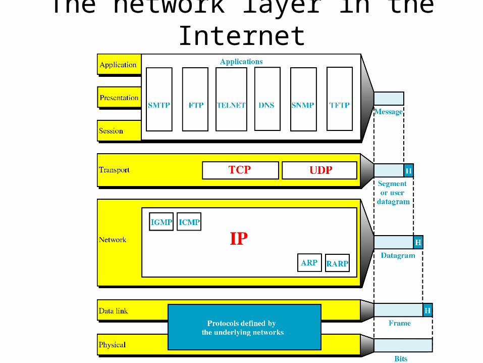
The network layer in the Internet
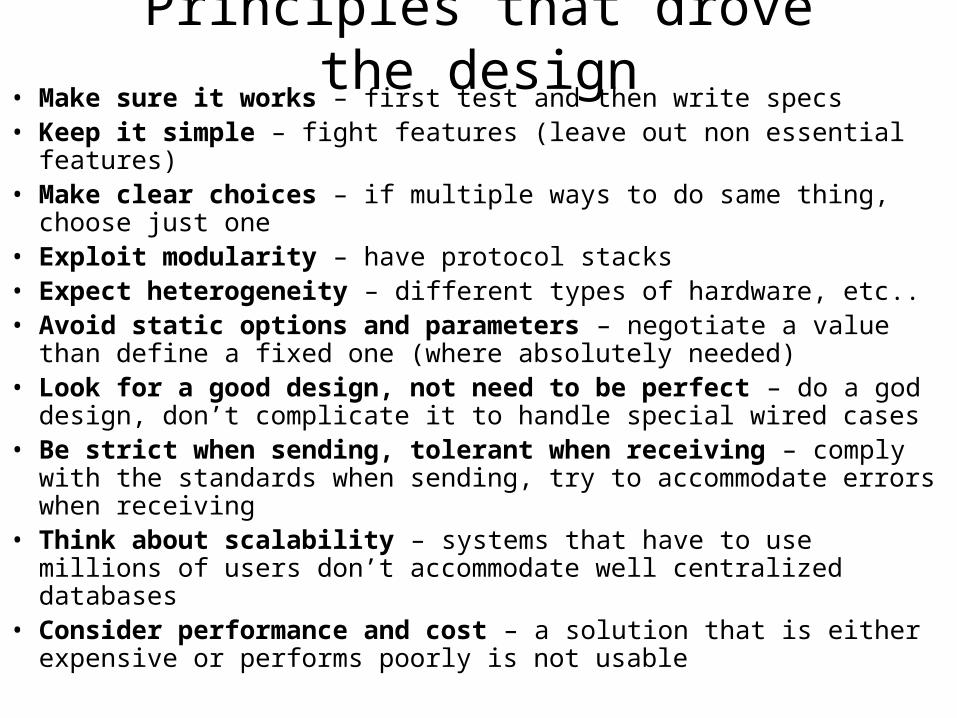
Principles that drove the design• Make sure it works – first test and then write specs• Keep it simple – fight features (leave out non essential features)• Make clear choices – if multiple ways to do same thing, choose just
one• Exploit modularity – have protocol stacks• Expect heterogeneity – different types of hardware, etc..• Avoid static options and parameters – negotiate a value than define
a fixed one (where absolutely needed)• Look for a good design, not need to be perfect – do a god design,
don’t complicate it to handle special wired cases• Be strict when sending, tolerant when receiving – comply with the
standards when sending, try to accommodate errors when receiving• Think about scalability – systems that have to use millions of users
don’t accommodate well centralized databases• Consider performance and cost – a solution that is either expensive
or performs poorly is not usable
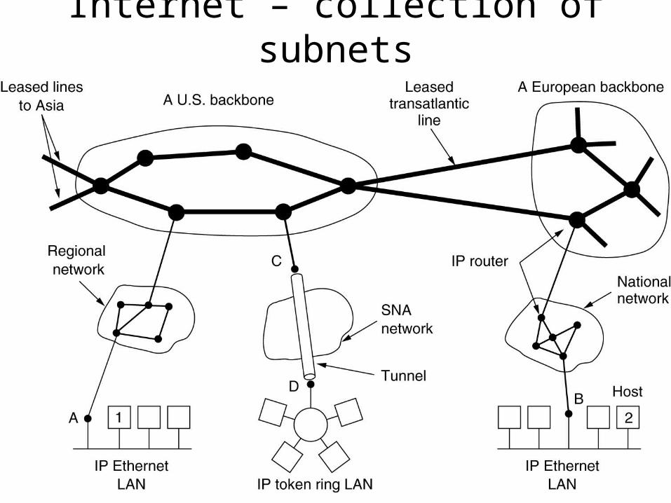
Internet – collection of subnets
Internet Protocol (IP)• The glue that holds together the Internet• Provides a best-efforts (not guaranteed) way to transport
datagrams from source to destination• Workflow:
– The transport layer takes the data streams and breaks them into datagrams (in theory they can be up to 64KB, but in practice they are no more than 1500 bytes to map naturally on the ETH payload)
– Each datagram is transmitted through the Internet (possible being fragmented into smaller pieces as it goes)
– When all pieces get to the destination machine, they are reassembled by the network layer into the original datagram
– This datagram is handed to the transport layer which inserts it into the receiving process input stream
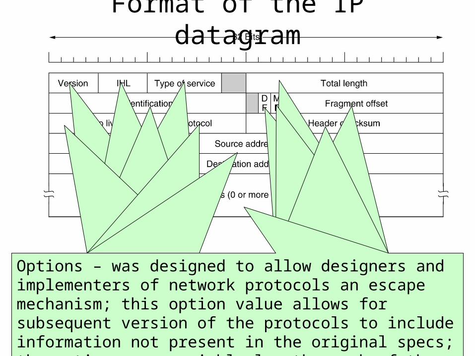
Format of the IP datagram
Versioning (keeps track of the versioning control). Currently we can have IPV4 (0100) or IPV6 (0110)Header Length – how long the header is in 32 bit-words; the minimum value is 5, which applies when no option is present; maximum value is 15 giving a maximum of 60 bytes for the header, when options are present (thus options field is limited to 40 bytes)
Type of service – defines how the datagram should be handled; it includes bits that define priority of the datagram; it also include bits that define the type of service the sender desires, such as level of throughput, reliability and delay; most of the times, this filed is completely ignored by routers
Total length – includes everything in the datagram, both header and data; the maximum length is 65,535 bytes; at this stage, this limit is OK, but with future gigabit networks, larger datagrams may be needed
Identification – is needed to allow the destination host to determine which datagram a newly arrived fragment belongs to. All the fragments of the datagram contains the identification field.
DF – bit specifying Don’t Fragment; this is helpful for systems that can’t put back together the fragments of a datagramMF – stands for More Fragments; all fragments except the last one have this bit set. It is needed to know when the fragments of a datagram have arrived
Fragment offset – tells where in the current datagram the current fragments belongs. All fragments, except the last one have to be multiple of 8 bytes (elementary fragment unit); since 13 bits are provided, there are a number of 8192 fragments per datagram, giving a maximum datagram length of 65536 bytes
Time to live – is a counter used to limit the packets life times; it is suppose to count time in seconds, allowing a maximum life time of 255 seconds, but in practice it counts only hops. When it hits 0, the packet is discarded and a warning packet is sent back to the host; this feature prevents datagrams from going around forever.
Protocol – tells which transport process to give it to…in other words is specifies the transport layer protocol (TCP, UDP, etc…)Header checksum – verifies only the header; the algorithm is to add up all 16 bit half words as they arrive, using one’s complement arithmetic and then take one’s complement result; the header checksum must be computed at each hope, since there are values in the header that modifies (i.e. hops count)
Source address and destination address indicate the network number and host number; we will see next what that means;Options – was designed to allow designers and implementers of network protocols an escape mechanism; this option value allows for subsequent version of the protocols to include information not present in the original specs; the options are variable length, each of them beginning with one byte identifying the option.
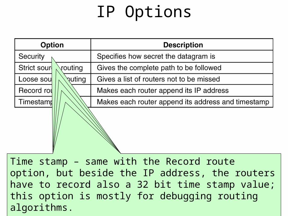
Security – i.e., a military router might use this field not to route through certain countries; in practice, all of the routers ignore it, so it can be used to spy easily on interesting stuff …
Strict source routing – gives the complete path from source to destination, as a list of IP address (sequence). The datagram is forced to follow that exact route; useful when routing tables are corrupted or for timing measures.
Loose source routing – requires the packet to traverse the list of routers specified, and in the specified order; it allows a pass through other routers on the way; this is useful when avoiding or force passing through certain countries (economical or political reasons)
Record route – tells the routers along the way to append their address to the option list. This allows tracking down of bugs in routing algorithms. At first, ARPANET was having at most 9 routers…so 40 bytes was plenty…but now this is too short.
Time stamp – same with the Record route option, but beside the IP address, the routers have to record also a 32 bit time stamp value; this option is mostly for debugging routing algorithms.
IP Options
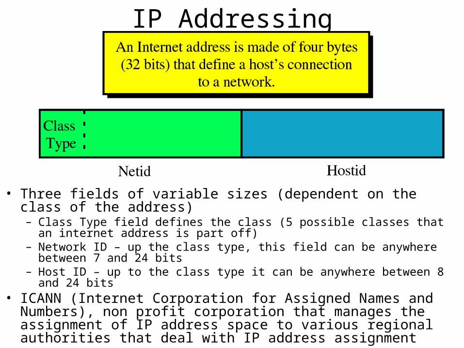
IP Addressing
• Three fields of variable sizes (dependent on the class of the address)– Class Type field defines the class (5 possible classes that an internet address is
part off)– Network ID – up the class type, this field can be anywhere between 7 and 24
bits– Host ID – up to the class type it can be anywhere between 8 and 24 bits
• ICANN (Internet Corporation for Assigned Names and Numbers), non profit corporation that manages the assignment of IP address space to various regional authorities that deal with IP address assignment
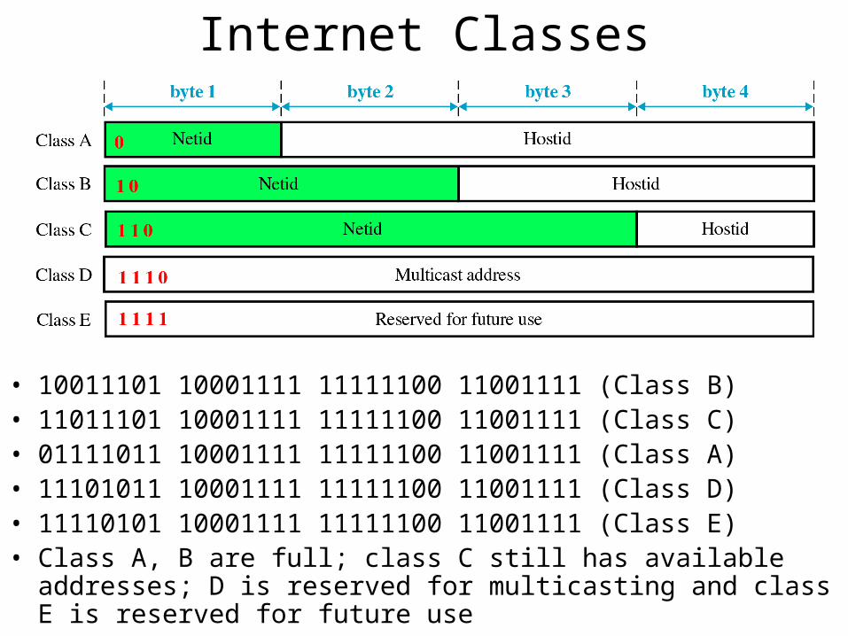
Internet Classes
• 10011101 10001111 11111100 11001111 (Class B)• 11011101 10001111 11111100 11001111 (Class C)• 01111011 10001111 11111100 11001111 (Class A)• 11101011 10001111 11111100 11001111 (Class D)• 11110101 10001111 11111100 11001111 (Class E)• Class A, B are full; class C still has available addresses; D is reserved
for multicasting and class E is reserved for future use
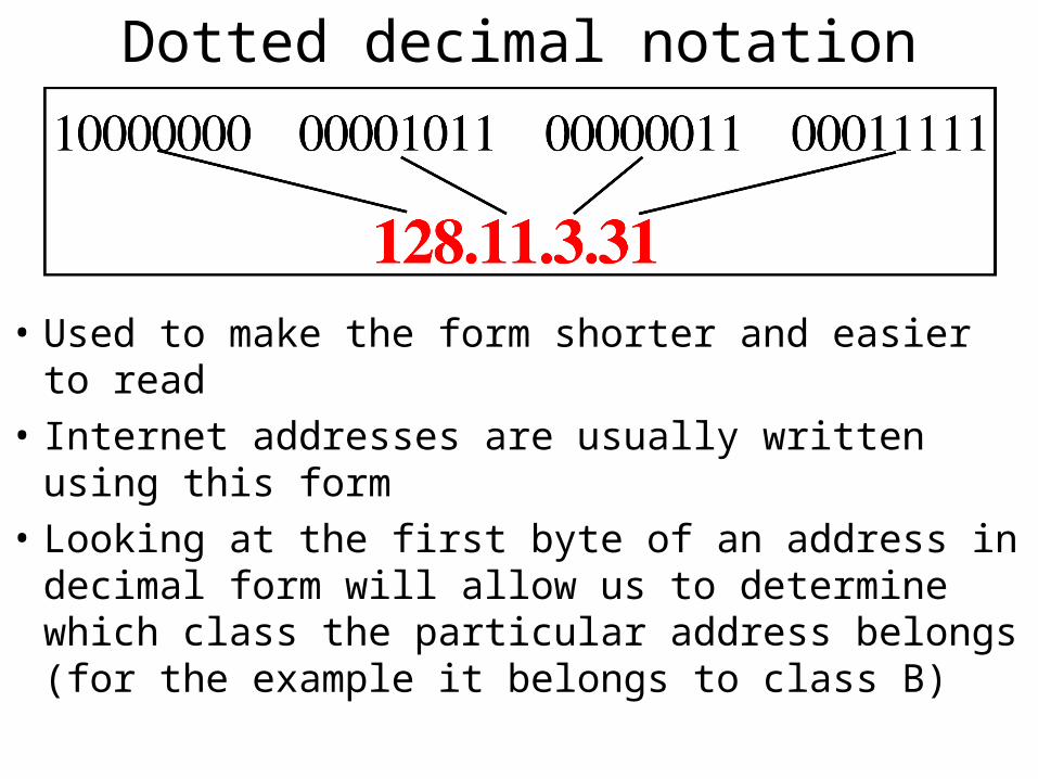
Dotted decimal notation
• Used to make the form shorter and easier to read
• Internet addresses are usually written using this form
• Looking at the first byte of an address in decimal form will allow us to determine which class the particular address belongs (for the example it belongs to class B)
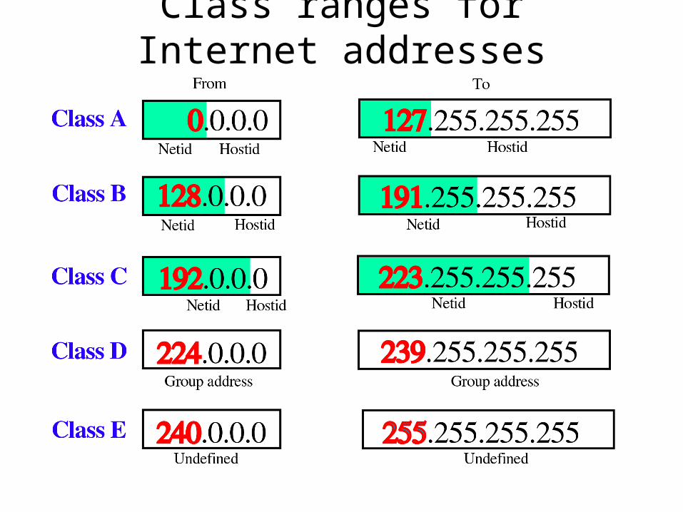
Class ranges for Internet addresses
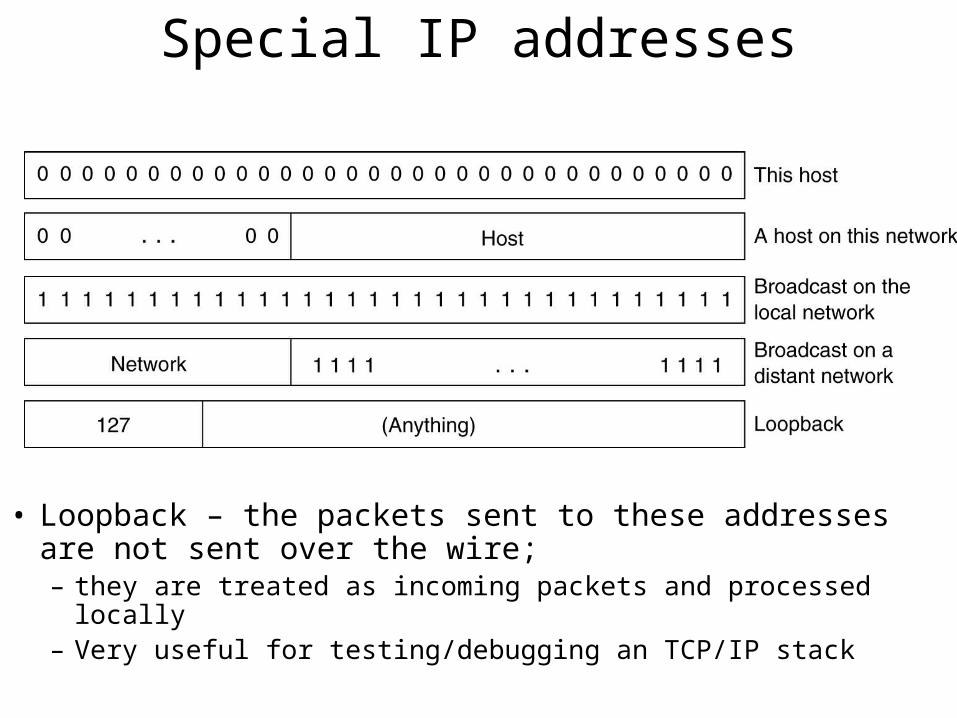
Special IP addresses
• Loopback – the packets sent to these addresses are not sent over the wire;– they are treated as incoming packets and processed locally– Very useful for testing/debugging an TCP/IP stack
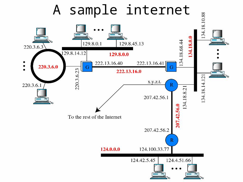
A sample internet
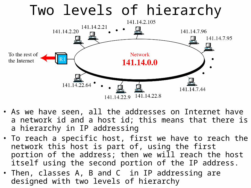
Two levels of hierarchy
• As we have seen, all the addresses on Internet have a network id and a host id; this means that there is a hierarchy in IP addressing
• To reach a specific host, first we have to reach the network this host is part of, using the first portion of the address; then we will reach the host itself using the second portion of the IP address.
• Then, classes A, B and C in IP addressing are designed with two levels of hierarchy
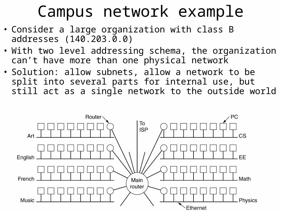
Campus network example• Consider a large organization with class B addresses
(140.203.0.0)• With two level addressing schema, the organization can’t
have more than one physical network• Solution: allow subnets, allow a network to be split into
several parts for internal use, but still act as a single network to the outside world
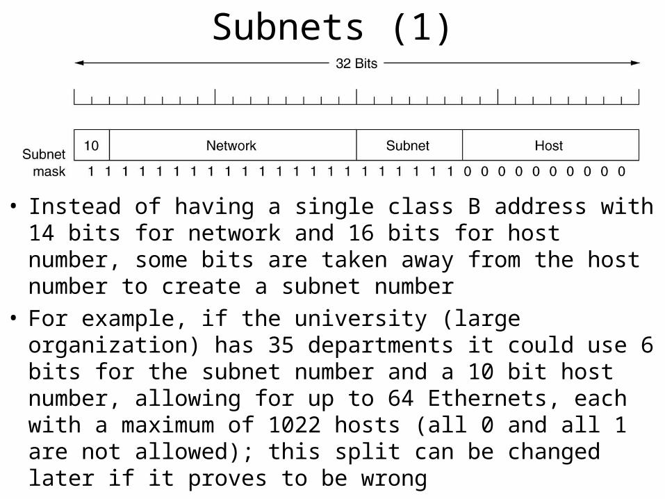
Subnets (1)
• Instead of having a single class B address with 14 bits for network and 16 bits for host number, some bits are taken away from the host number to create a subnet number
• For example, if the university (large organization) has 35 departments it could use 6 bits for the subnet number and a 10 bit host number, allowing for up to 64 Ethernets, each with a maximum of 1022 hosts (all 0 and all 1 are not allowed); this split can be changed later if it proves to be wrong
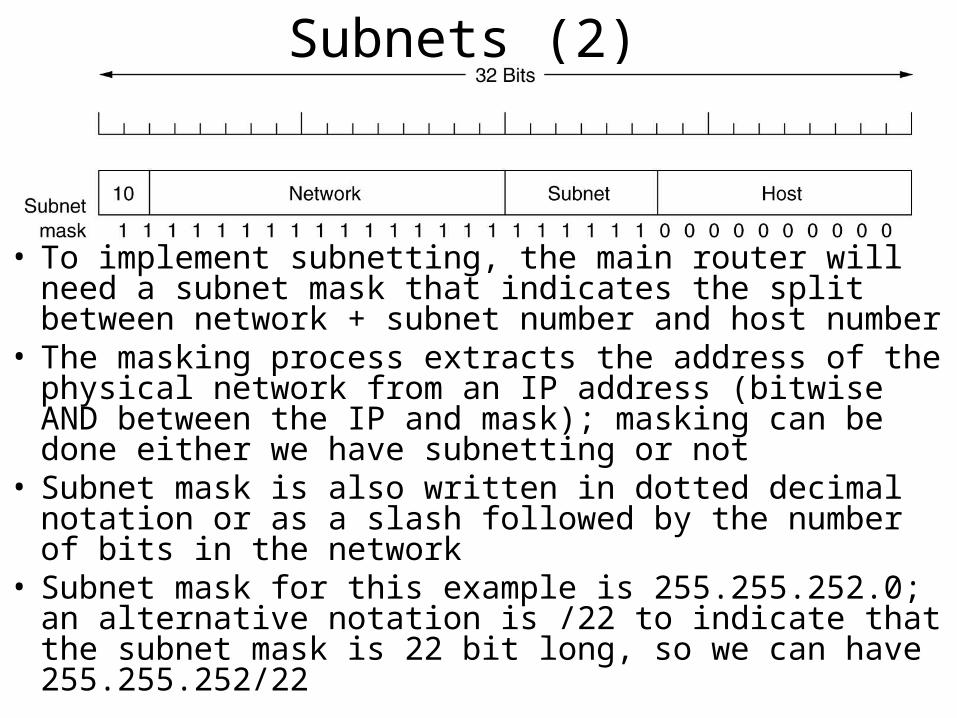
Subnets (2)
• To implement subnetting, the main router will need a subnet mask that indicates the split between network + subnet number and host number
• The masking process extracts the address of the physical network from an IP address (bitwise AND between the IP and mask); masking can be done either we have subnetting or not
• Subnet mask is also written in dotted decimal notation or as a slash followed by the number of bits in the network
• Subnet mask for this example is 255.255.252.0; an alternative notation is /22 to indicate that the subnet mask is 22 bit long, so we can have 255.255.252/22
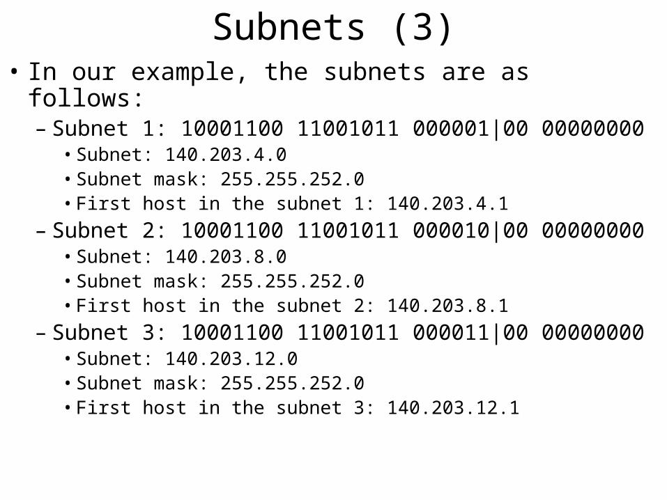
Subnets (3)• In our example, the subnets are as follows:
– Subnet 1: 10001100 11001011 000001|00 00000000• Subnet: 140.203.4.0• Subnet mask: 255.255.252.0• First host in the subnet 1: 140.203.4.1
– Subnet 2: 10001100 11001011 000010|00 00000000• Subnet: 140.203.8.0• Subnet mask: 255.255.252.0• First host in the subnet 2: 140.203.8.1
– Subnet 3: 10001100 11001011 000011|00 00000000• Subnet: 140.203.12.0• Subnet mask: 255.255.252.0• First host in the subnet 3: 140.203.12.1
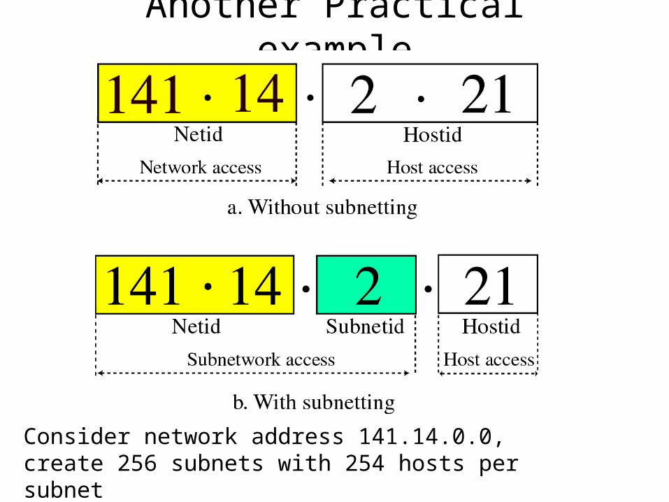
Another Practical example
Consider network address 141.14.0.0, create 256 subnets with 254 hosts per subnet
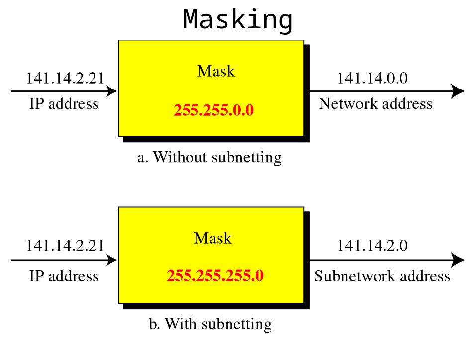
Masking
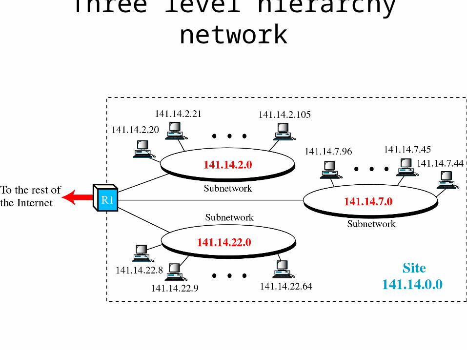
Three level hierarchy network
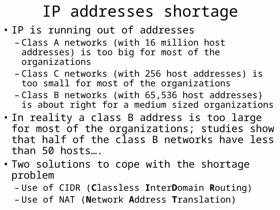
IP addresses shortage• IP is running out of addresses
– Class A networks (with 16 million host addresses) is too big for most of the organizations
– Class C networks (with 256 host addresses) is too small for most of the organizations
– Class B networks (with 65,536 host addresses) is about right for a medium sized organizations
• In reality a class B address is too large for most of the organizations; studies show that half of the class B networks have less than 50 hosts….
• Two solutions to cope with the shortage problem– Use of CIDR (Classless InterDomain Routing)– Use of NAT (Network Address Translation)
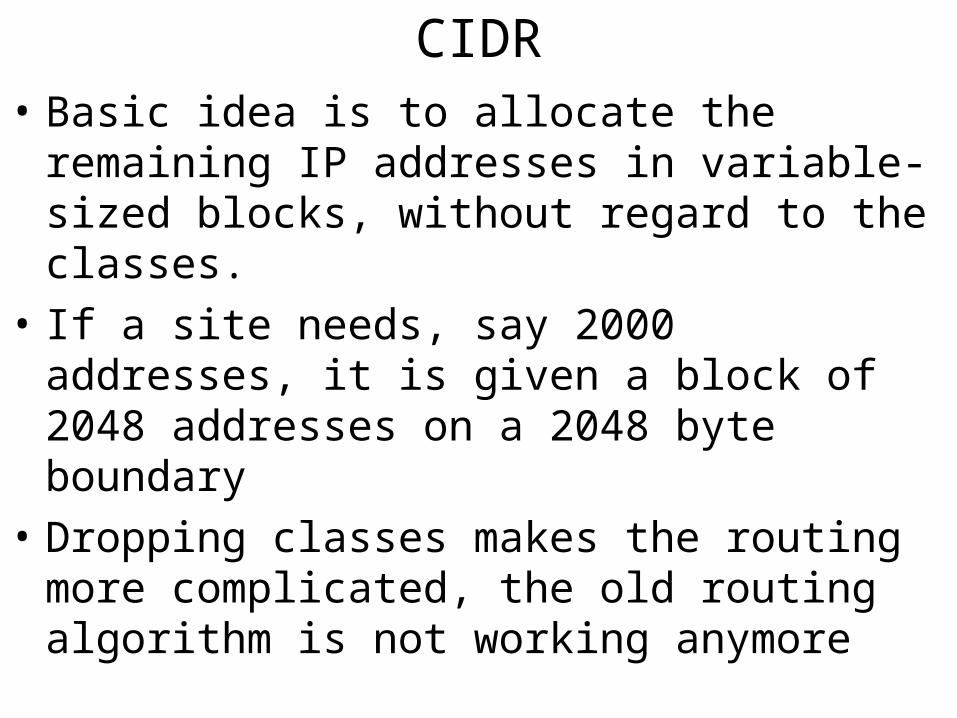
CIDR• Basic idea is to allocate the remaining IP addresses
in variable-sized blocks, without regard to the classes.
• If a site needs, say 2000 addresses, it is given a block of 2048 addresses on a 2048 byte boundary
• Dropping classes makes the routing more complicated, the old routing algorithm is not working anymore
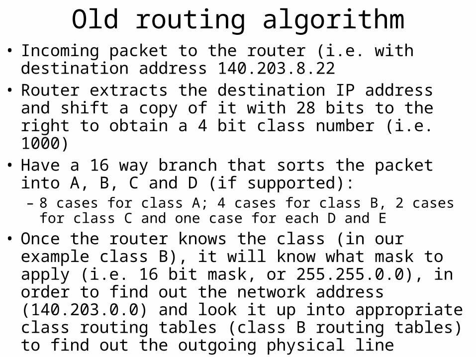
Old routing algorithm• Incoming packet to the router (i.e. with destination address
140.203.8.22• Router extracts the destination IP address and shift a copy
of it with 28 bits to the right to obtain a 4 bit class number (i.e. 1000)
• Have a 16 way branch that sorts the packet into A, B, C and D (if supported):– 8 cases for class A; 4 cases for class B, 2 cases for class C and one
case for each D and E
• Once the router knows the class (in our example class B), it will know what mask to apply (i.e. 16 bit mask, or 255.255.0.0), in order to find out the network address (140.203.0.0) and look it up into appropriate class routing tables (class B routing tables) to find out the outgoing physical line
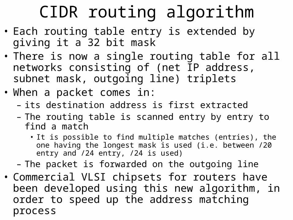
CIDR routing algorithm• Each routing table entry is extended by giving it a 32 bit
mask• There is now a single routing table for all networks
consisting of (net IP address, subnet mask, outgoing line) triplets
• When a packet comes in:– its destination address is first extracted– The routing table is scanned entry by entry to find a match
• It is possible to find multiple matches (entries), the one having the longest mask is used (i.e. between /20 entry and /24 entry, /24 is used)
– The packet is forwarded on the outgoing line
• Commercial VLSI chipsets for routers have been developed using this new algorithm, in order to speed up the address matching process
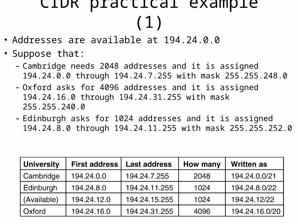
CIDR practical example (1)
• Addresses are available at 194.24.0.0• Suppose that:
– Cambridge needs 2048 addresses and it is assigned 194.24.0.0 through 194.24.7.255 with mask 255.255.248.0
– Oxford asks for 4096 addresses and it is assigned 194.24.16.0 through 194.24.31.255 with mask 255.255.240.0
– Edinburgh asks for 1024 addresses and it is assigned 194.24.8.0 through 194.24.11.255 with mask 255.255.252.0

CIDR practical example (2)• The routing tables all over the world will update to
contain the following entries:– C: 11000010 00011000 00000000 00000000 with mask
11111111 11111111 11111000 00000000– E: 11000010 00011000 00001000 00000000 with mask
11111111 11111111 11111100 00000000– O: 11000010 00011000 00010000 00000000 with mask
11111111 11111111 11110000 00000000
• Packet coming for destination 194.24.17.4 or in binary: 11000010 00011000 00010001 00000100– First it is ANDed with Cambridge mask
• 11000010 000110000 00010000 00000000, this value doesn’t match the Cambridge base address
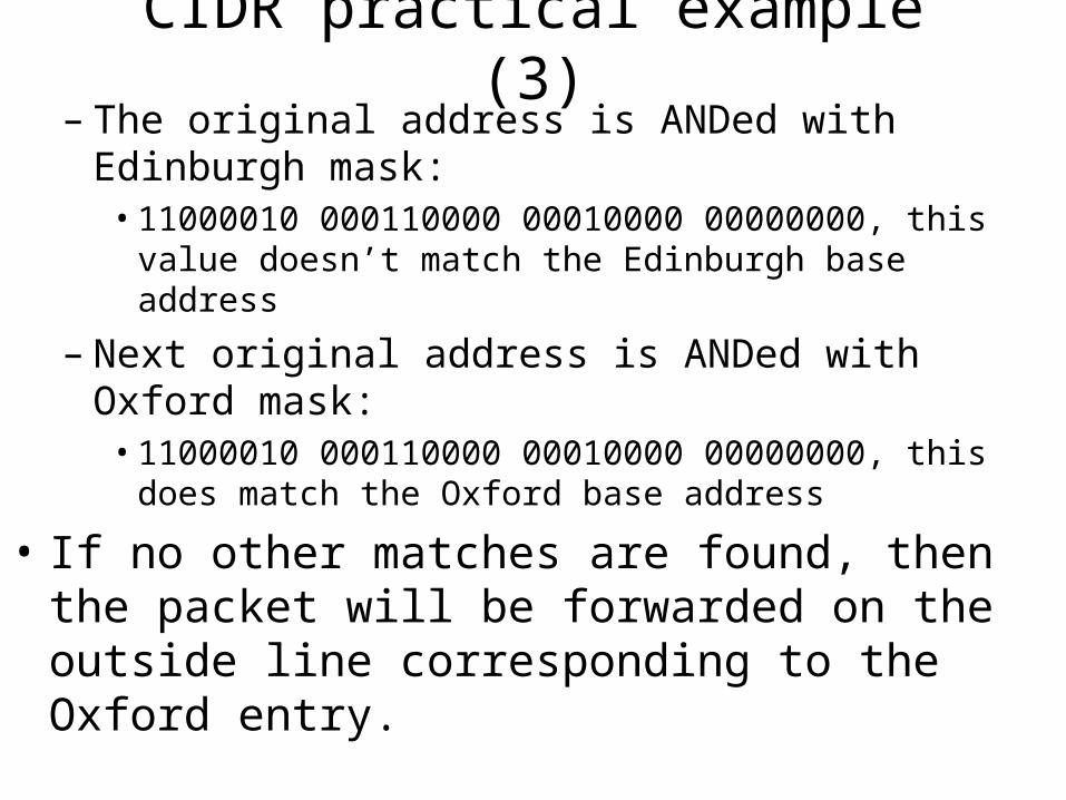
CIDR practical example (3)– The original address is ANDed with Edinburgh mask:
• 11000010 000110000 00010000 00000000, this value doesn’t match the Edinburgh base address
– Next original address is ANDed with Oxford mask:• 11000010 000110000 00010000 00000000, this does match the
Oxford base address
• If no other matches are found, then the packet will be forwarded on the outside line corresponding to the Oxford entry.
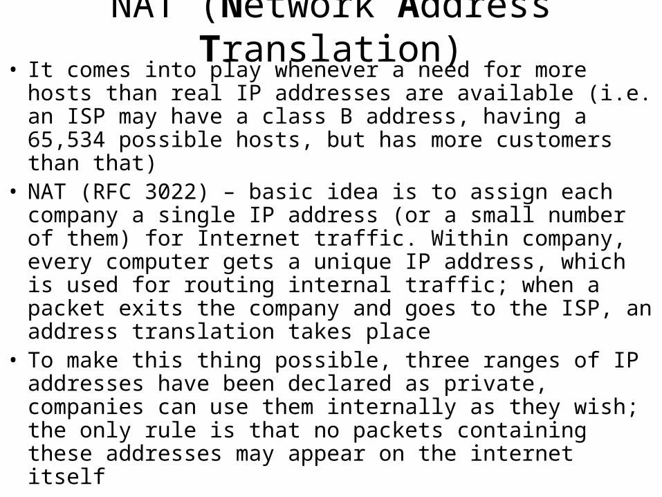
NAT (Network Address Translation)• It comes into play whenever a need for more hosts than real
IP addresses are available (i.e. an ISP may have a class B address, having a 65,534 possible hosts, but has more customers than that)
• NAT (RFC 3022) – basic idea is to assign each company a single IP address (or a small number of them) for Internet traffic. Within company, every computer gets a unique IP address, which is used for routing internal traffic; when a packet exits the company and goes to the ISP, an address translation takes place
• To make this thing possible, three ranges of IP addresses have been declared as private, companies can use them internally as they wish; the only rule is that no packets containing these addresses may appear on the internet itself
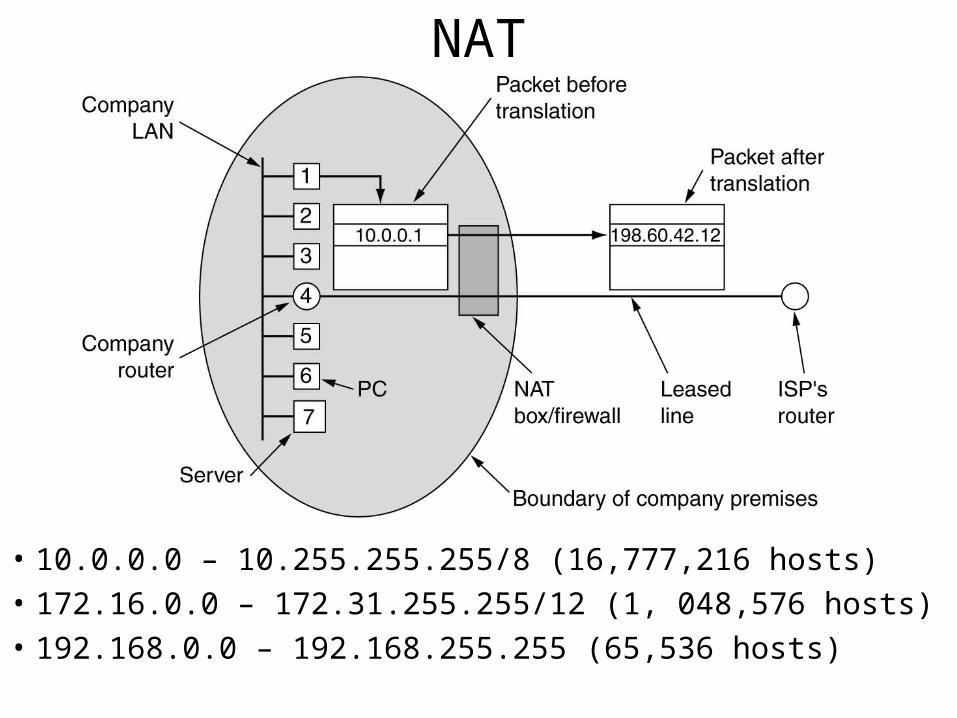
NAT
• 10.0.0.0 – 10.255.255.255/8 (16,777,216 hosts)
• 172.16.0.0 – 172.31.255.255/12 (1, 048,576 hosts)
• 192.168.0.0 – 192.168.255.255 (65,536 hosts)
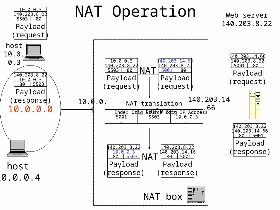
NAT Operation
host10.0.0.3
Web server140.203.8.22
10.0.0.0
host10.0.0.4
10.0.0.1
Payload(request)
5503 80
10.0.0.3140.203.8.22
Payload(request)
5503 80
10.0.0.3140.203.8.22
Payload(request)
5001 80
140.203.14.66140.203.8.22
NAT
140.203.14.66
Orig Source Port Orig IP AddressIndex5503 10.0.0.35001
… ……
NAT translation table
Payload(response)
80 5503
140.203.8.2210.0.0.3
Payload(response)
80 5001
140.203.8.22140.203.14.16
NAT
NAT box
Payload(response)
80 5503
140.203.8.2210.0.0.3
Payload(request)
5001 80
140.203.14.66140.203.8.22
Payload(response)
80 5001
140.203.8.22140.203.14.66
NAT problems• Violates the architecture of IP model, which states that
every host worldwide should be identified by a unique IP• Changes the Internet from a connectionless network in a
kind of connection-oriented network• Violates the most elementary rule of protocol layering, that
layer k should not make any assumption of what layer k+1 put in the payload
• Will not work with any protocols on the Internet (beside TCP or UDP)
• Some applications insert IP addresses in the text (payload); the receiver will extract these addresses and use them; NAT will not work with those applications since it doesn’t know about this insertion (i.e. MS Messenger)
Internet Control Protocols
• ICMP (Internet Control Message Protocol)
• ARP (Address Resolution Protocol)
• RARP (Reverse Address Resolution Protocol)
• BOOTP (BOOTstrap Protocol, alternative to RARP)
• DHCP (Dynamic Host Configuration Protocol)
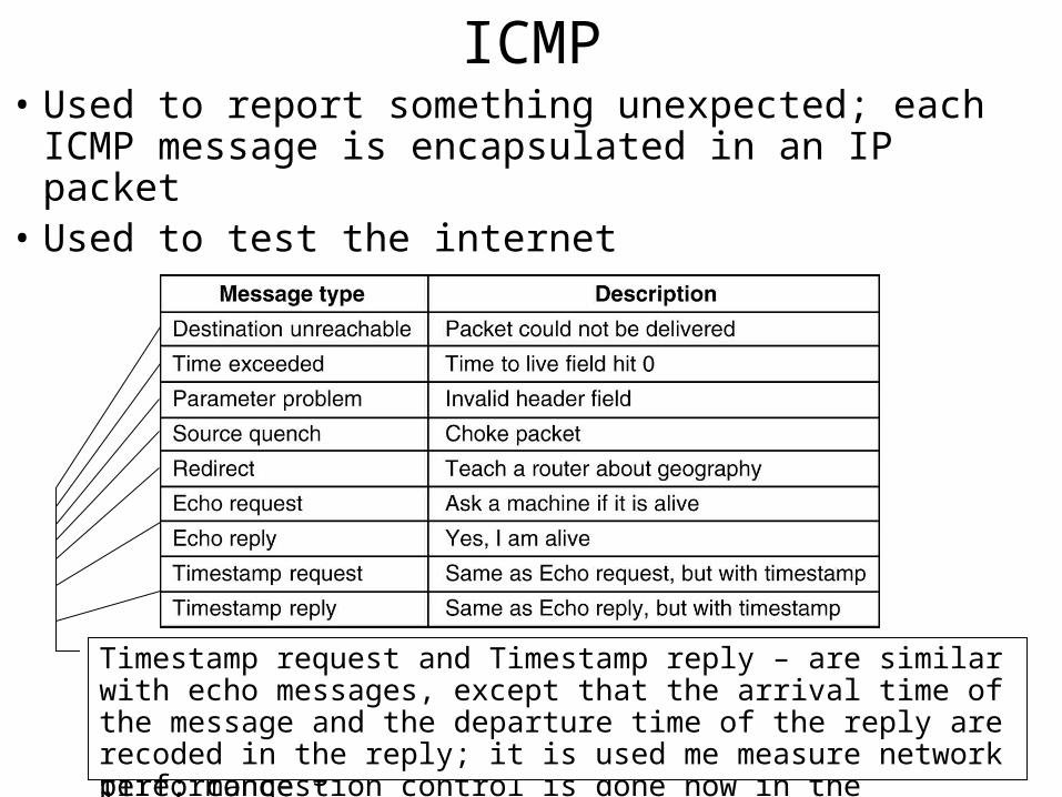
ICMP• Used to report something unexpected; each ICMP
message is encapsulated in an IP packet• Used to test the internet
Destination unreachable – is used when the subnet or a router can’t locate the destination or when a packet with DF bit set can’t be delivered because a “small packet” network stands in the way
Time exceeded – is sent when a packet is dropped because its counter reached zero; this event is a symptom that packets are looping, there is an enormous congestion or the timer values were set to low
Parameter problem – indicates that an illegal value has been detected in a header field; this message indicates a bug in the sender’s IP software or possible in the transited routers
Source quench – message formerly used to slow down stations that were sending too many packets; it is not used anymore, because when congestion occurs, those packets tend to throw more fuel into the fire; congestion control is done now in the transport layer
Redirect – is used when a router notices that a packets seem to be routed wrong. It is used by the router to tell the sending host about the probable error
Echo and Echo reply – are used to see if a given destination is reachable and alive; upon receiving the echo message, the receiving station is suppose to answer with the echo reply message
Timestamp request and Timestamp reply – are similar with echo messages, except that the arrival time of the message and the departure time of the reply are recoded in the reply; it is used me measure network performance
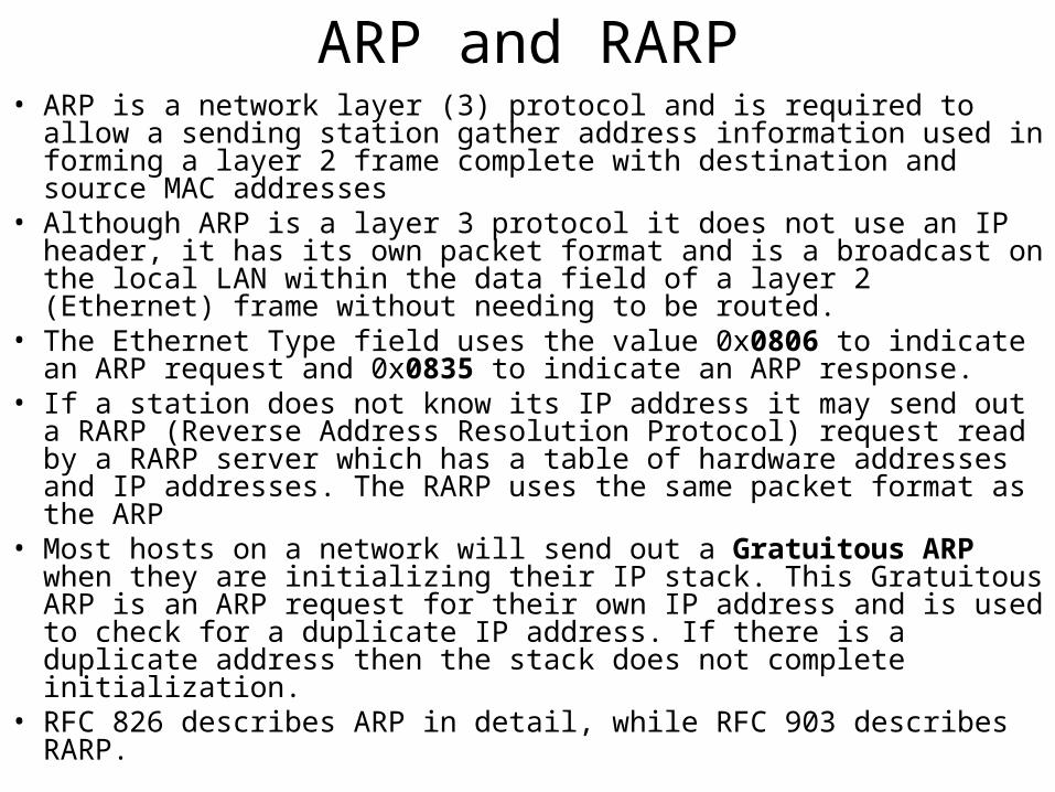
ARP and RARP• ARP is a network layer (3) protocol and is required to allow a sending
station gather address information used in forming a layer 2 frame complete with destination and source MAC addresses
• Although ARP is a layer 3 protocol it does not use an IP header, it has its own packet format and is a broadcast on the local LAN within the data field of a layer 2 (Ethernet) frame without needing to be routed.
• The Ethernet Type field uses the value 0x0806 to indicate an ARP request and 0x0835 to indicate an ARP response.
• If a station does not know its IP address it may send out a RARP (Reverse Address Resolution Protocol) request read by a RARP server which has a table of hardware addresses and IP addresses. The RARP uses the same packet format as the ARP
• Most hosts on a network will send out a Gratuitous ARP when they are initializing their IP stack. This Gratuitous ARP is an ARP request for their own IP address and is used to check for a duplicate IP address. If there is a duplicate address then the stack does not complete initialization.
• RFC 826 describes ARP in detail, while RFC 903 describes RARP.
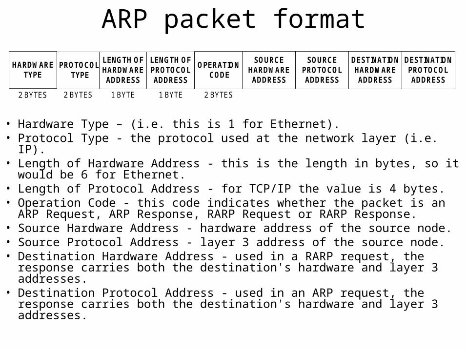
ARP packet format
• Hardware Type – (i.e. this is 1 for Ethernet).• Protocol Type - the protocol used at the network layer (i.e. IP). • Length of Hardware Address - this is the length in bytes, so it would
be 6 for Ethernet. • Length of Protocol Address - for TCP/IP the value is 4 bytes. • Operation Code - this code indicates whether the packet is an ARP
Request, ARP Response, RARP Request or RARP Response. • Source Hardware Address - hardware address of the source node. • Source Protocol Address - layer 3 address of the source node. • Destination Hardware Address - used in a RARP request, the response
carries both the destination's hardware and layer 3 addresses. • Destination Protocol Address - used in an ARP request, the response
carries both the destination's hardware and layer 3 addresses.
HARDWARETYPE
PROTOCOL TYPE
LENGTH OFHARDWAREADDRESS
SOURCEHARDWAREADDRESS
2 BYTES 2 BYTES 2 BYTES
LENGTH OFPROTOCOLADDRESS
1 BYTE
OPERATION CODE
SOURCEPROTOCOLADDRESS
DESTINATIONHARDWAREADDRESS
DESTINATIONPROTOCOLADDRESS
1 BYTE
RARP, BOOTP and DHCP• Given an data-link address (i.e. Ethernet address) what is
the corresponding net address (IP address)– RARP
• Is using a broadcasting destination address of all 1s (it is not forwarded by the routers), so a RARP server needs to be in each network
– BOOTP• Is using UDP messages, so they will be forwarded over routers• It is specifically designed for diskless stations, so it provides additional
information, such as IP of the file server holding the operating system image, etc…
• It requires manual configuration of the tables mapping the IP addresses with Ethernet addresses
– DHCP (Dynamic Host Configuration Protocol)• Special server that allows automatic and manual IP assignment• It may require a DHCP relay agent on the local networks, so the
DISCOVER packet would be forwarded outside the local LAN• RFC 2131 and RFC2132
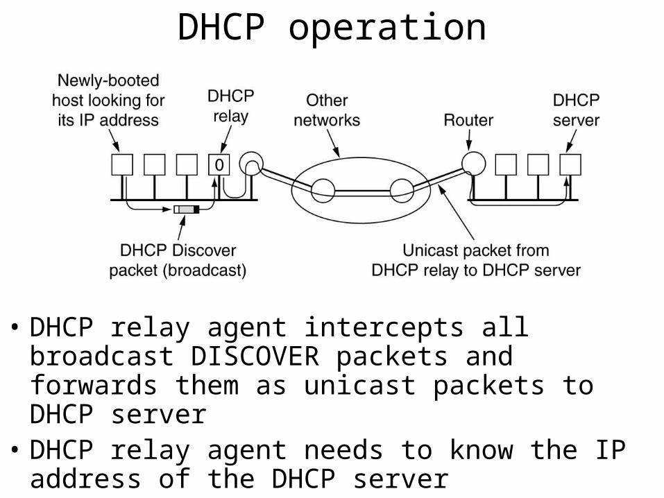
DHCP operation
• DHCP relay agent intercepts all broadcast DISCOVER packets and forwards them as unicast packets to DHCP server
• DHCP relay agent needs to know the IP address of the DHCP server
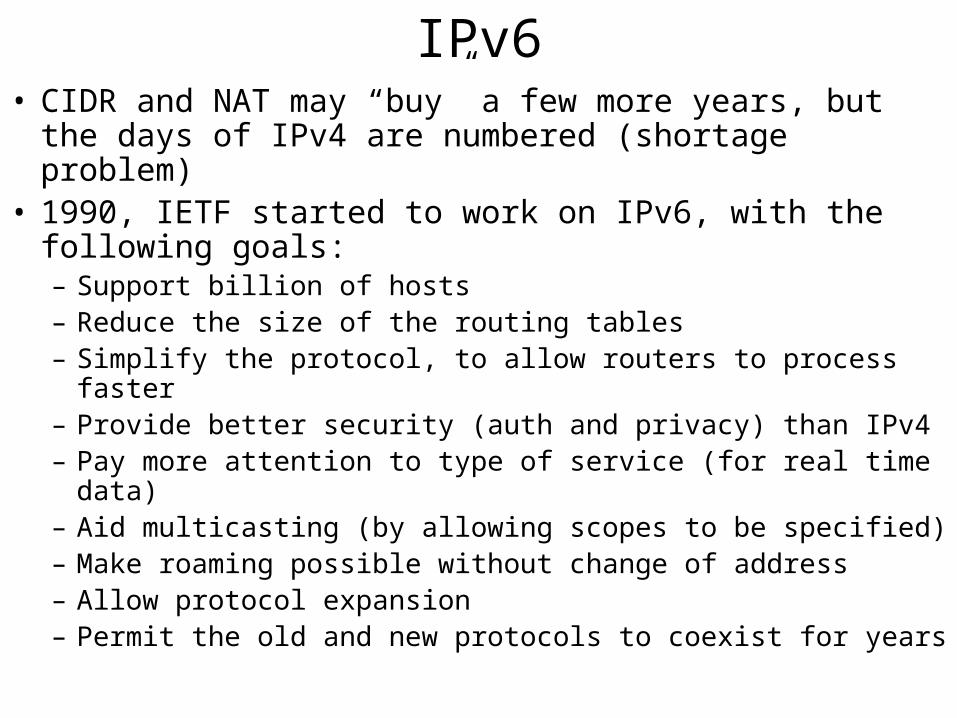
IPv6• CIDR and NAT may “buy” a few more years, but the days
of IPv4 are numbered (shortage problem)• 1990, IETF started to work on IPv6, with the following
goals:– Support billion of hosts– Reduce the size of the routing tables– Simplify the protocol, to allow routers to process faster– Provide better security (auth and privacy) than IPv4– Pay more attention to type of service (for real time data)– Aid multicasting (by allowing scopes to be specified)– Make roaming possible without change of address– Allow protocol expansion– Permit the old and new protocols to coexist for years
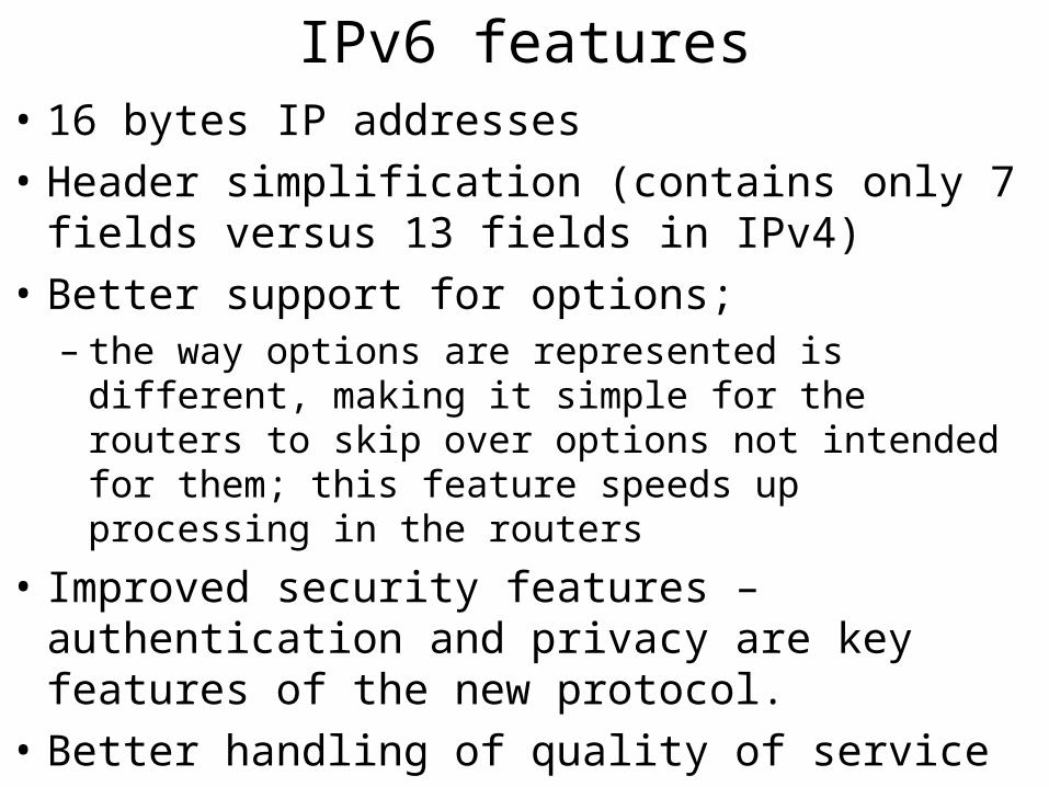
IPv6 features• 16 bytes IP addresses
• Header simplification (contains only 7 fields versus 13 fields in IPv4)
• Better support for options; – the way options are represented is different, making it
simple for the routers to skip over options not intended for them; this feature speeds up processing in the routers
• Improved security features – authentication and privacy are key features of the new protocol.
• Better handling of quality of service
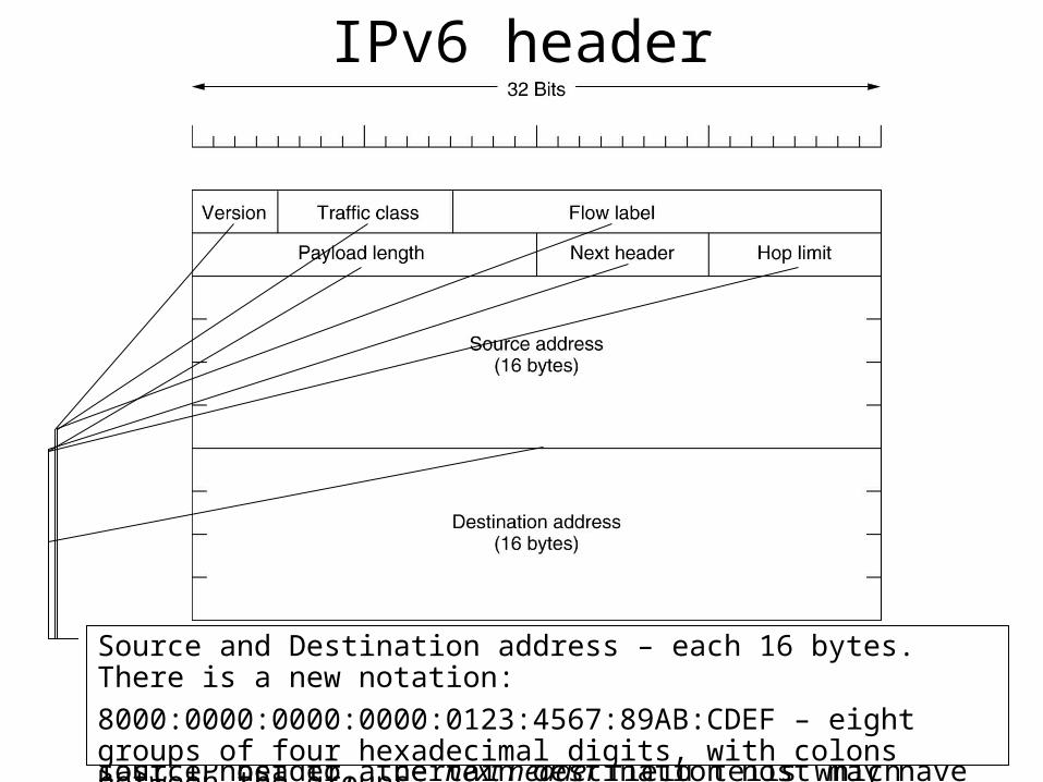
IPv6 header
Version field is always 6 for IPv6 or 4 for IPv4; routers will be able to examine this field and process the packet accordinglyTraffic class – is used to distinguish between packets with different real time delivery requirementsFlow label – experimental field, used to allow a source and a destination to setup a pseudo-connection with particular properties and requirements; i.e. a stream of packets on a certain source host to a certain destination host may have stringent delay requirements, thus need reserved bandwidth.
Payload length – how many bytes follow the 40byte header of the packet. The 40 bytes header is not counted anymore in the length of the packet.Next header – there can be optional (extra) headers for the given packet. This field tells which (if any) of the currently supported six extension headers follow this header; if this header is the last IP header, the next header field tells which transport protocol handler (TCP, UDP, etc..) to pass the packet to
Hop limit – used to keep packets from living forever; it is practically the same time to live field as in IPv4 header.Source and Destination address – each 16 bytes. There is a new notation:
8000:0000:0000:0000:0123:4567:89AB:CDEF – eight groups of four hexadecimal digits, with colons between the groups
IPv4 versus IPv6• Protocol filed – was taken out because the next header field
tells what follows the last IP header (i.e. UDP or TCP segment)
• Fragmentation fields were removed – IPV6 hosts are expected to dynamically determine the datagram
size to use.
– The minimum has been raised from 576 to 1280 to allow 1024 bytes of data and many headers
– If an IPV6 host sends a too large packet, the routers will issue an error message; this message tells the host to break up all future packets to that destination
• Checksum field – not existing because calculating it greatly reduces performance. However, since transport layer have their own checksum, it is not making sense to do it twice
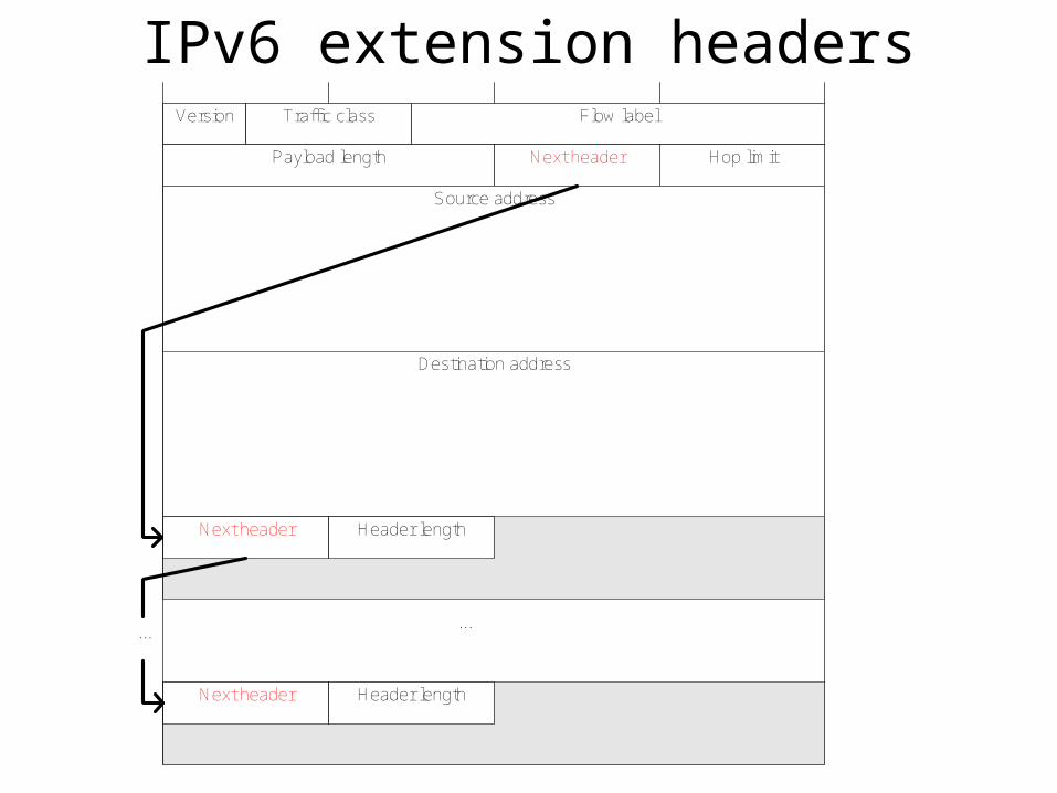
IPv6 extension headersVersion Traffic class Flow label
Payload length Next header Hop limit
Source address
Destination address
Next header Header length
...
Next header Header length
...
IPv6 extension headers
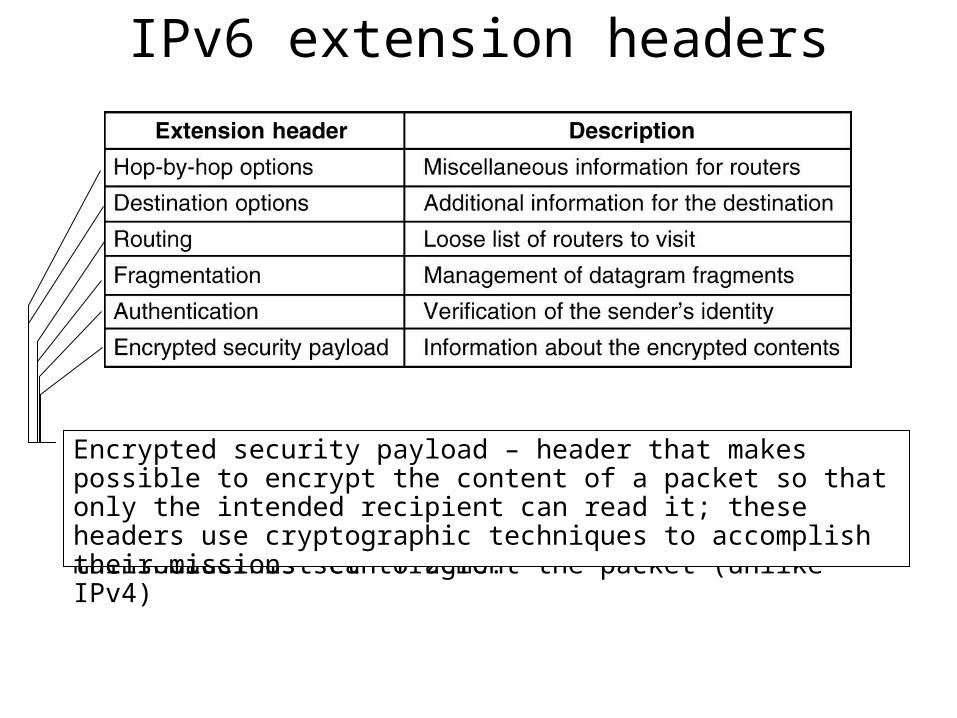
It is used to carry information that all the headers along the path must examine. One option has been defined so far: support for datagrams that exceeds 64K; when used, the payload length field in the main header is set to zero.
Destination options - intended for fields that may be interpreted only at the destination hostRouting header – lists one or more routers that must be visited prior to reaching the destinationFragmentation – deals with fragmentation, similarly with IPv4; this header holds the datagram identifier, fragment number and a bit telling whether more fragments will follow; in IPv6 only the source host can fragment the packet (unlike IPv4)
Authentication – header that provides a mechanism so the receiving station is sure of who sent the packet (who is the source)Encrypted security payload – header that makes possible to encrypt the content of a packet so that only the intended recipient can read it; these headers use cryptographic techniques to accomplish their mission
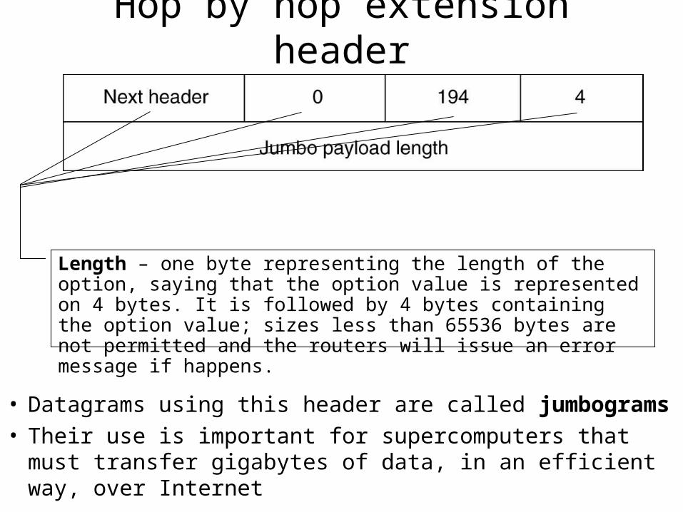
Hop by hop extension header
• Datagrams using this header are called jumbograms• Their use is important for supercomputers that must transfer
gigabytes of data, in an efficient way, over Internet
Next header – byte that shows what kind of header is next Header length – how long the hop-by-hop header is in bytes, excluding the first 8 bytes that are mandatoryType – for this case is code 194 showing that this option defines the datagram sizeLength – one byte representing the length of the option, saying that the option value is represented on 4 bytes. It is followed by 4 bytes containing the option value; sizes less than 65536 bytes are not permitted and the routers will issue an error message if happens.
References• Behrouz A. Forouzan – Data Communications and
Networking, ISBN: 0-07-118160-1
• Andrew S. Tanenbaum – Computer Networks, ISBN: 0-13066102-3
Additional Slides
More on Networking Devices
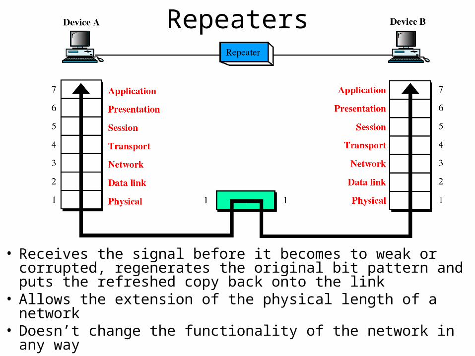
Repeaters
• Receives the signal before it becomes to weak or corrupted, regenerates the original bit pattern and puts the refreshed copy back onto the link
• Allows the extension of the physical length of a network• Doesn’t change the functionality of the network in any way
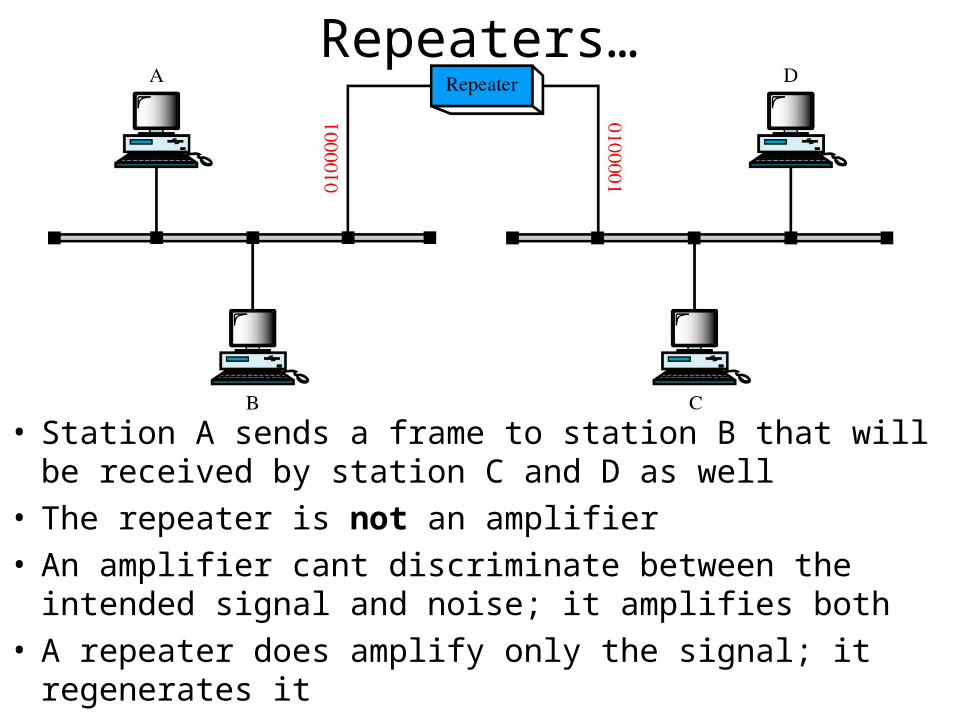
Repeaters…
• Station A sends a frame to station B that will be received by station C and D as well
• The repeater is not an amplifier • An amplifier cant discriminate between the intended signal
and noise; it amplifies both• A repeater does amplify only the signal; it regenerates it
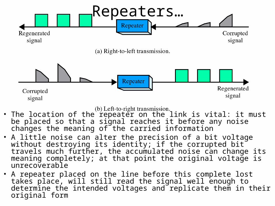
Repeaters…
• The location of the repeater on the link is vital: it must be placed so that a signal reaches it before any noise changes the meaning of the carried information
• A little noise can alter the precision of a bit voltage without destroying its identity; if the corrupted bit travels much further, the accumulated noise can change its meaning completely; at that point the original voltage is unrecoverable
• A repeater placed on the line before this complete lost takes place, will still read the signal well enough to determine the intended voltages and replicate them in their original form
Bridges
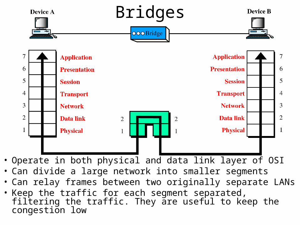
• Operate in both physical and data link layer of OSI• Can divide a large network into smaller segments• Can relay frames between two originally separate LANs• Keep the traffic for each segment separated, filtering the
traffic. They are useful to keep the congestion low
Bridges…
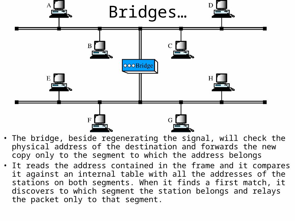
• The bridge, beside regenerating the signal, will check the physical address of the destination and forwards the new copy only to the segment to which the address belongs
• It reads the address contained in the frame and it compares it against an internal table with all the addresses of the stations on both segments. When it finds a first match, it discovers to which segment the station belongs and relays the packet only to that segment.
Bridges…
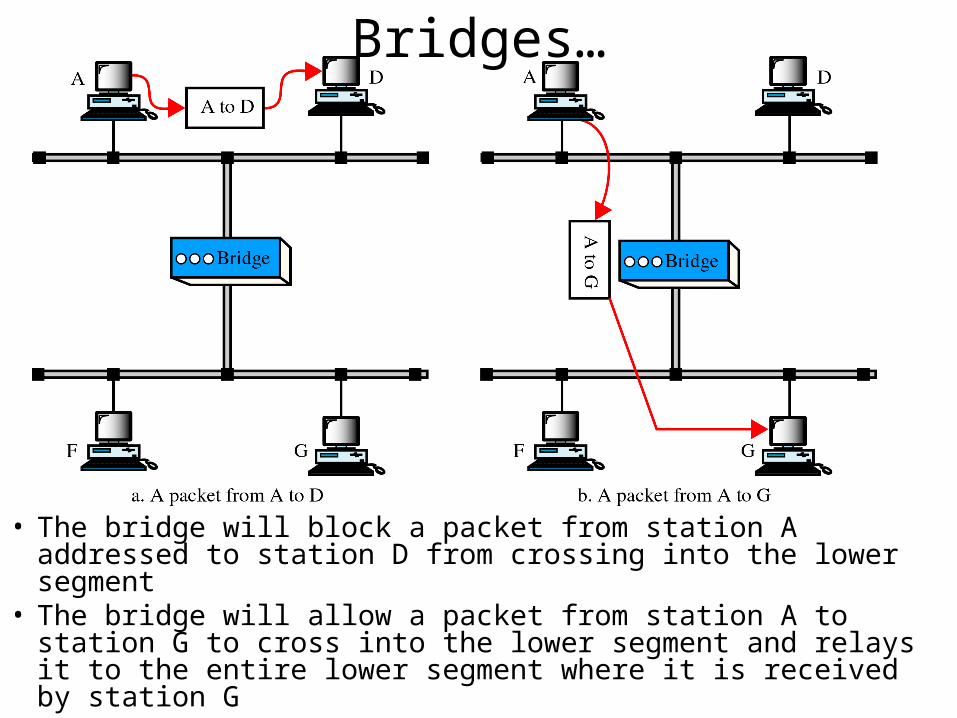
• The bridge will block a packet from station A addressed to station D from crossing into the lower segment
• The bridge will allow a packet from station A to station G to cross into the lower segment and relays it to the entire lower segment where it is received by station G
Simple bridge• Links two segments and contains a table that lists he
addresses of all the stations included in each of them• Addresses must be entered manually (before a simple bridge
can be used, an operator has to sit down and enter the addresses of every station)
• Whenever a new station has been added, the table has to be modified; when a station is removed, the table has to be modified, the newly invalid address has to be deleted
• The bridge is simple to build and inexpensive to manufacture but installation and maintenance are time consuming, probably more expensive than the price saving resulted out of the cheap manufacturing cost
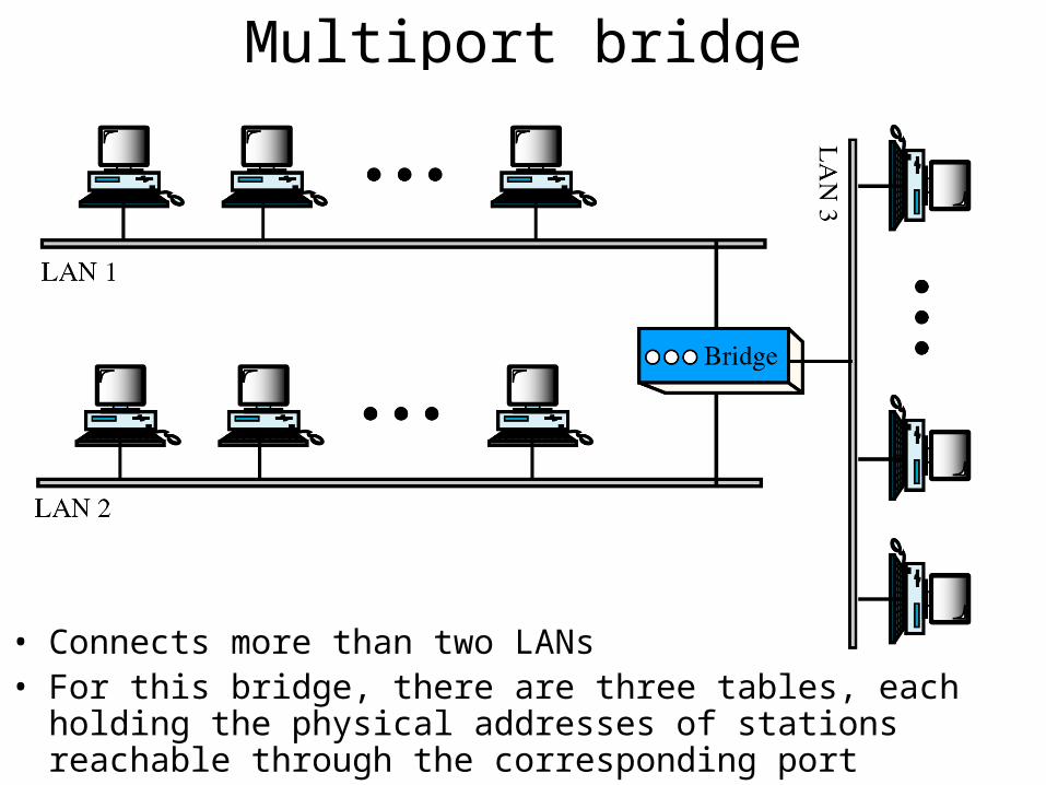
Multiport bridge
• Connects more than two LANs• For this bridge, there are three tables, each holding the physical
addresses of stations reachable through the corresponding port
Transparent bridge• This learning bridge builds its table of station addresses on
its own as it performs bridge functions• When first installed, its table is empty; as it encounters each
packet, it looks at both the destination and the source addresses. It checks the destination and decides where to send the packet; if it doesn’t recognize yet the destination address, it sends the packet on all of the ports
• It uses the source address to build its table; with the first packet transmitted by each station, it learns the segment associated with that station
• Continuing this process even after each station has been learned, it assures that it is self-updating
Bridges connecting different LANs• Frame format – frames from different LANs have different
formats (i.e. Ethernet frame and Token Ring frame)• Payload size – the size of the data that can be encapsulated
in a frame varies from protocol to protocol (i.e. Ethernet has 1500 + headers while Token Ring has 4500 + headers)
• Data rate – different protocols use different data rates (i.e. 10 Mb/s for Ethernet and 16Mb/s for Token Ring)
• Address bit order – the bit order of addresses in different types of LANs is not the same (i.e. a bridge should reverse an address if it is connecting an Ethernet LAN to a Token Ring LAN)
• Other issues: collision, acknowledgements, priority, etc…
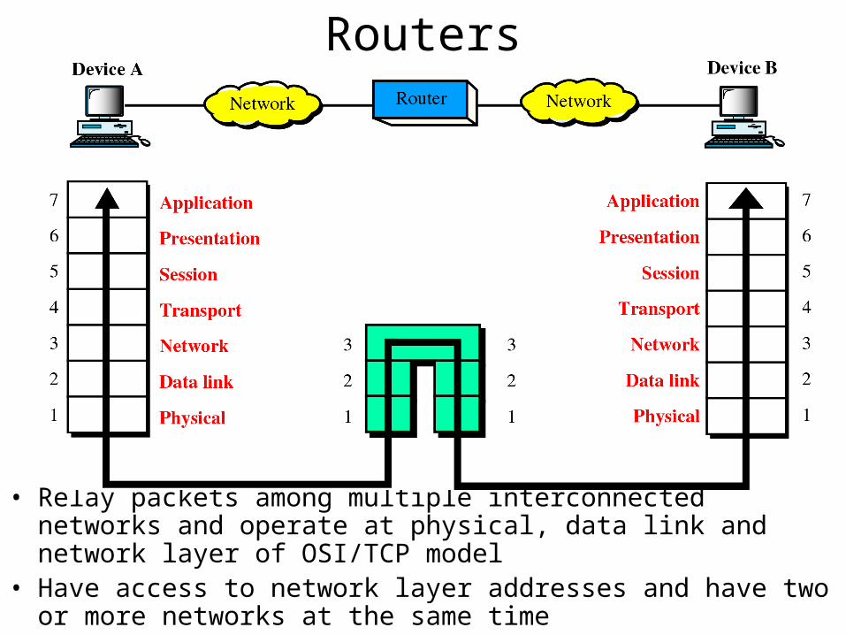
Routers
• Relay packets among multiple interconnected networks and operate at physical, data link and network layer of OSI/TCP model
• Have access to network layer addresses and have two or more networks at the same time
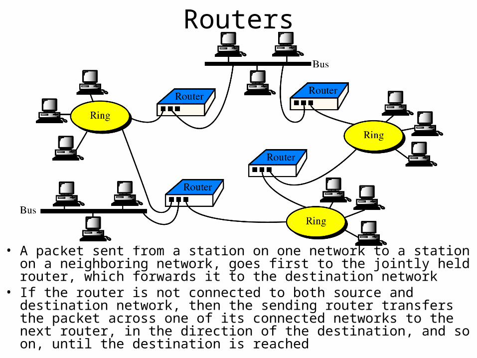
Routers
• A packet sent from a station on one network to a station on a neighboring network, goes first to the jointly held router, which forwards it to the destination network
• If the router is not connected to both source and destination network, then the sending router transfers the packet across one of its connected networks to the next router, in the direction of the destination, and so on, until the destination is reached