The NAVY/NASA Engine Program (NNEP89)-- Interfacing … · of Complex Chemical Equilibrium...
28
NASA Contractor Report 187208 The NAVY/NASA Engine Program (NNEP89)-- Interfacing the Program for the Calculation of Complex Chemical Equilibrium Compositions (CEC) Sanford Gordon Sanford Gordon & Associates Cleveland, Ohio for Sverdrup Technology, Inc. Lewis Research Center Group Brook Park. Ohio ( _ , ...... _ ..... _. 1 : ,_iVt'!;_'-'t 1 : < '' .;1 ;,] [ _ ,.> C,,r!f:, I 7 s r # 1 : ' T # "t . _ ]-r i c, < L.r _.. Jr ii ) ' t b, September 1991 , '7, r - I i! /'I[C_,L OSL.L ?It 4<',_ - ', ._ :i Prepared for Lewis Research Center Under Contract NAS3-24105 N/ A National Aeronautics and Space Administration https://ntrs.nasa.gov/search.jsp?R=19910022827 2018-07-15T20:02:27+00:00Z
Transcript of The NAVY/NASA Engine Program (NNEP89)-- Interfacing … · of Complex Chemical Equilibrium...

NASA Contractor Report 187208
The NAVY/NASA Engine Program (NNEP89)--
Interfacing the Program for the Calculationof Complex Chemical EquilibriumCompositions (CEC)
Sanford Gordon
Sanford Gordon & Associates
Cleveland, Ohio
for
Sverdrup Technology, Inc.
Lewis Research Center Group
Brook Park. Ohio
( _ , ...... _ ..... _. 1 : ,_iVt'!;_'-'t
1 : < '' .;1 ;,] [ _ ,.> C,,r!f:, I 7
s r # 1 : ' T # "t. _ ]-r i c, < L.r _..
Jr ii ) ' t b,
September 1991
, '7, r -
I i! /'I[C_,L
OSL.L ?It
4<',_ - ', ._ :i
Prepared for
Lewis Research Center
Under Contract NAS3-24105
N/ ANational Aeronautics and
Space Administration
https://ntrs.nasa.gov/search.jsp?R=19910022827 2018-07-15T20:02:27+00:00Z


CONTENTS
SUMMARY
INTRODUCTION
INPUT INSTRUCTIONS
Options for Running With or Without Dissociation
REACTANT Card Images
FARRAY and OARRAY
Debugging
DESCRIPTION OF SUBROUTINES
Defining the Chemical System
DBURNR
GASGEN
MIXER
NEWOF
REACT
SETEN
THERME
THERMODYNAMIC DATA
APPENDIXES
A-SYMBOLS
B-SAMPLE PROBLEMS
REFERENCES
TABLES
1
2
2
2
3
4
5
6
6
7
8
10
10
10
11
11
12
13
13
15
19
20


THE NAVY/NASA ENGINE PROGRAM (NNEP8g) - INTERFACING THE PROGRAM FOR THE
CALCULATION OF COMPLEX CHEMICAL EQUILIBRIUM COMPOSITIONS (CEC)
Sanford Gordon
Sanford Gordon & Associates
Cleveland, Ohio
SUMMARY
The Navy/NASA Engine Program - NNEP, is a general computer program for
calculating aircraft engine performance. NNEP has been used extensively to
calculate the design and off-design (matched) performance of a broad range of
turbine engines, ranging from subsonic turboprops to variable cycle engines
for supersonic transports. Recently, however, there has been increased
interest in applications for which NNEP is not capable of simulating, such as
the use of alternate fuels including cryogenic fuels and the inclusion of
chemical dissociation effects at high temperatures. To overcome these
limitations, NNEP has now been extended by including a general chemical
equilibrium method. This permits consideration of any propellant system and
the calculation of performance with dissociation effects. The new extended
program is referred to as NNEP8g.

INTRODUCTION
The Navy/NASA Engine Program - NNEP, is a general computer program for
calculating aircraft engine performance and is described in references 1-4.
NNEP has been used extensively to calculate the design and off-design
(matched) performance of a broad range of turbine engines, ranging from
subsonic turboprops to variable cycle engines for supersonic transports. The
NNEP computer code has gained wide acceptance and is currently in use at over
70 universities, commercial companies and other government agencies.
Recently, however, there has been increased interest in applications for which
NNEP is not capable of simulating, such as the use of alternate fuels
including cryogenic fuels and the inclusion of chemical dissociation effects
at high temperatures. To overcome these limitations, NNEP has now been
extended by including the general equilibrium method of reference 5 (referred
to here as CET86). This permits consideration of any propellant system and
the calculation of performance with dissociation effects. The new extended
program described herein will be referred to as NNEP89.
Inasmuch as the option of obtaining performance based on no dissociation is
still available, all of the subroutines in NNEP have been retained, but with
appropriate revisions to accommodate the new dissociation option in NNEP89.
Many of the subroutines in CET86 were eliminated (such as those pertaining to
shock and detonations) and changes were made in a number of the remainingsubroutines to join CET86 with NNEP. In addition, two new subroutines were
prepared: GASGEN and THERME. Subroutine GASGEN extends the modelling
capabilities of NNEP by permitting the burning of energetic combinations such
as hydrogen and oxygen or methane and oxygen in a gas generator. Subroutine
THERME was prepared to replace function THERM when thermodynamic properties of
dissociated mixtures are required.
This report presents information on input and output which is required in
addition to the information already presented in references 4 and 5; a
description of some of the changes or additions to several subroutines; and a
few sample problems. For the user of this program, the principal newinformation concerning input preparation is discussed in several sections
under "INPUT INSTRUCTIONS". Additional input information for the gas
generator is given in the section "Subroutine GASGEN". The other sections,
which are primarily concerned with changes or additions to some of the
routines from the NNEP or CET86 programs, are not necessary for using the
program but are included for the sake of completeness.
INPUT INSTRUCTIONS
Options for Running With or Without Dissociation
No changes in input are required if NNEP89 is to run as NNEP was previously,
i.e., if engine performance without chemical dissociation is desired. To
obtain performance with dissociation, three additional types of input are
required. The first simply requires the index ICEC to be set equal to I inthe first &D namelist. If ICEC=I, then subroutine MAINEQ is called from

subroutine INPUTto initiate all the preparation that is required for chemicalequilibrium calculations such as reading in the REACTANTinformation and theappropriate thermodynamic data. The second type of input requires thepreparation of REACTANTcard images similar to those discussed in reference 5.Changesthat were madein the reference 5 format for REACTANTSare discussedin the next section. The third type of input involves the arrays FARRAYandOARRAYwhich are discussed in a later section. If a run is to be madeinvolving the gas generator, then someadditional input is required in theSPECarray for the generator. The details of this input are discussed in thesection "Subroutine GASGEN".
In addition to the required types of input, someoptional input variables havebeen provided for debugging purposes (see section "Debugging").
REACTANTCard Images
As mentioned previously, REACTANTcard images are required for the option ofchemical dissociation. A maximumof 24 reactants is permitted for anycomputer run. The first reactant must always be air. The format for thesecard images, presented in reference 5, has been changed somewhatfor thisprogram. The revised format is given in Table I. The revisions permit theoption of specifying for each reactant either an assigned enthalpy (asdiscussed in reference 5) or a heat of combustion. Twoenergy units arecurrently permitted for the assigned enthalpy: calories or joules. The heatof combustion is in units of BTU/Ib. The units for the energy value given incolumns 54-62 are now indicated by the index in column 71 as follows:
Column71 Columns54-62
Blank Enthalpy in units of cal/formula weight
J Enthalpy in units of joules/formula weight
Heat of combustion in units of BTU/Ib
Heat of combustion may be specified as the lower heating value (LHV) or thehigher heating value (HHV). (The LHVis the heat of combustion value when thecombustion product H20is in the gaseous state, whereas for the HHVvalue theH20is in the liquid state.) To specify the HHV,the heat of combustion valuein card columns 54-62 must be put in as a negative number. Otherwise, theprogram assumesit is the LHV. Columns73-80 are used for combustionefficiency. These columns are used only in conjunction with the heat ofcombustion. If columns 73-80 are blank for a given heat of combustion, adefault value of I is used by the program. The heat of combustion andefficiency are automatically converted in the program to an equivalentassigned enthalpy value as required by the chemical equilibrium routines. Areactant mayalso be one of the possible products of combustion included inthe set of thermodynamic data used in NNEP89(see section THERMODYNAMICDATA).Whenthis occurs, the program provides an option for automatically calculatingthe enthalpy of the reactant at the temperature specified in columns 64-70.This is accomplished by putting zeros in columns 37 and 38. In reference 5,

the REACTANTcard image uses columns 46-53 to specify the relative weight ofthe reactant. In NNEP8gthese columns are not used, inasmuchas relativeweights of reactants are specified by the arrays FARRAYand OARRAY(seediscussion in next section). Temperature, in units of kelvin, is restrictedto columns 64-70. In reference 5, temperature is given in columns 64-71. Ifzeros are put in columns 37 and 38 for somereactant as discussed above, thena temperature in columns 64-70 is required. Otherwise, temperature in thesecolumns is optional and maybe omitted or included for informational purposesonly. Also, in reference 5, a reactant is identified as a fuel or as anoxidant by an "F" or "0" in column 72. This is no longer required in NNEP89but maybe used for informational purposes. As each REACTANTcard image isread, NNEP89automatically assigns it a number in the order it is read. Thisreactant order number is required by the user for the preparation of theFARRAYand OARRAYarrays (see next section).
FARRAYand OARRAY
Only one fuel can be specified in NNEP for any particular run. The arrays
FARRAY (12,200) and OARRAY (12,200) are part of the arrangement for making
NNEP89 completely general in regard to the number and type of reactants which
can be considered and for specifying which reactants are to be added to which
engine component. At present, the FARRAY is used only for burners and gas
generators while the OARRAY is used only for gas generators. FARRAY is usedfor fuels and OARRAY for oxidants. The first index, with dimension 12, is
used to specify from ! to 6 pairs of numbers. The first number of each pair
is the reactant order number (see section Subroutine REACT) and the second
number of each pair is its weight relative to the total weight of reactants
being added to the engine component specified by the second index. If only
one reactant is added to a particular component, its relative weight is I.
The second index, with dimension 200, specifies the engine component number.
The FARRAY may be used with or without the OARRAY. Some examples will help to
clarify the use of these arrays.
Example I. In this simple case, just one fuel, REACTANT 2, with a relative
weight fraction of I., is being added to the burner, which, in this example,
is component 3. Then FARRAY(I,3)=2 and FARRAY(2,3)=I. The same information
is specified by setting FARRAY(I,3)=2,|.
Example 2. Two fuels are being added to the burner, component 5. These fuels
are REACTANT 2 with a weight fraction of 0.4 and REACTANT 3 with a weightfraction of 0.6. Then FARRAY(I,5)=2,.4,3,.6

Example3. The burner is component6, using REACTANT2 fuel. In addition,REACTANT3 (a fuel) and REACTANT4 (an oxidant) are being added to the gasgenerator, engine component5. Then
For the burner: FARRAY(I,6)=2,1.
For the gas generator: FARRAY(I,5)=3,1and OARRAY(I,5)=4,1.
Debugging
The CET86program provides for debugging with the index IDEBUG. SettingIDEBUGto somevalue other than zero gives intermediate output that is useful,for example, for finding programmingerrors, studying the iteration processand rate of convergence for obtaining chemical equilibrium, and for verifyingthat thermodynamic data have been properly prepared. Somediscretion shouldbe exercised in connection with using IDEBUGinasmuchas this option cangenerate an enormousamount of intermediate output in the NNEP89program (asmuchas a factor of IO0 comparedto the standard output). It is generallypreferable to use the CET86program for this type of debugging. Additionaldebugging capabilities have been provided in NNEP89by use of indices IDBUG,LDBUG,and NDBUG.All four debugging controls are part of namelist &INPT2.The default value for these controls is zero. At present, the followingintermediate output is obtained for the following values of IDBUG:
Value ofIDBUG Intermediate Output
I. Nameof the subroutine being called from amongthe
following subroutines:
COMPRS,DBURNR,GASGEN,HEATXC,INLET, MIXER,NOZZLE,
SPLITR, and TURBIN
2. Values of JCX, JMI, JM2, JPI, JP2 for current
subroutine. (from amongthe above subroutines)
(Also values of IWAYand IDONEfor subroutine INLET)
i. The output for IDBUG= I
2. Values of PECWT(see "Defining the Chemical System")
3. Value of stoichiometric f/a in DBURNRsubroutine

Value ofLDBUG
I °
2.
I I.
The output for IDBUG = 2
Details of convergence procedures for subroutines
DBURNR and GASGEN
Details of convergence procedures for subroutine
THERME (ID=8) (See "Subroutine THERME" for definition
of ID)
Value ofNDBUG
I 1. Details of convergence procedures for subroutine
THERME (ID:I,2,3 and 7)
An example of input containing a debug parameter is shown in APPENDIX B(TESTCASE: SEPARATE FLOW TURBOFAN).
DESCRIPTION OF SUBROUTINES
Defining the Chemical System
Several subroutines and COMMON regions are involved in defining a current
chemical system. The region WTREAC(24,IO0) contains the flow rates of up to
24 reactants (first index) for each of up to 100 flow stations (second index).
At the beginning of each subroutine that requires thermodynamic properties of
the flow, the flow rates from the immediately upstream component are read from
WTREAC and stored in region PECWT(24). In most subroutines, the incoming flow
remains unchanged. However, in several subroutines, additional reactants may
be added to the incoming flow. These additional reactants and their relative
amounts by weight are specified by information in FARRAY and OARRAY (see
section FARRAY and OARRAY). In those subroutines where the values of PECWT
change due to the addition of reactants, the new values of PECWT are stored inWTREAC.
When additional reactants are added, a new chemical system is automatically
set up by NNEP89 for the equilibrium calculations. This is accomplished by I)
calling subroutine REACT (which searches the reactants for all chemical
elements in the system); 2) calling SEARCH (to select all possible chemical
species in the system that are contained in the thermodynamic library) and 3)
setting NEWFA=I. When NEWFA=I, subroutine THERME will call NEWOF to set up
new relative atom ratios (kg-atoms/kg) for the chemical elements.

Subroutine DBURNR
An iterative procedure is required to find the f/a (fuel-to-air weight ratio)corresponding to an assigned burner-out temperature. Note that "fuel" in thef/a ratio includes any reactant that is carried on board including oxygen aswell as jet fuel, hydrogen, etc. For the no dissociation option, theiterative procedure described in reference NNEPwas not changed. However, forthe dissociation option, a different procedure is used and is described asfollows. A chemical equilibrium calculation for any f/a at the burner-outtemperature permits obtaining a corresponding value of ah defined as
Ah = Hp-Hr (])
where H_ is the enthalpy of the products at the assigned burner-out
temperature reaction and H_ is the enthalpy of the mixture of reactants. The
correct value for f/a is obtained when Ah = O. The iteration procedure
consists of setting up a linear equation for two values of f/a and their
corresponding Ah values and solving for an improved value of f/a by setting Ah
= 0 in the linear equation
f/a = mAh+b (2)
where
m = ((f/a)2-(f/a)1)/(Ah2-Ahl) (3a)
and
b = (f/a)2-mAh 2 (3b)
This improved value of f/a and its corresponding value Ah are used together
with one of the two previous sets of f/a's and Ah's to obtain an even closer
value of f/a by again using equations (2), (3a) and (3b). This procedure is
repeated until convergence is reached as defined by the following equation:
I ((fla)2-(fla)1)/(f/a)11 <0.000005 (4)
Initial estimates for two values of f/a are required to start the iteration
process. However, except for (f/a)s (the stoichiometric condition), f/a is adouble-valued function of burner-out temperature. That is, the same burner-
out temperature can be obtained by burning lean or rich. Therefore, different
sets of initial estimates for f/a are required for the lean or rich side of
stoichiometric. The specification of whether the burner is to burn lean, rich
or stoichiometric is accomplished by setting SPEC (It,N) as follows (where N
is the number of the burner component):
Burn condition Value of SPEC (11,N)
Iean 0
stoichiometric Irich 2

If SPEC(11,N)=1, no iteration for f/a is required inasmuch as (f/a)s is known
from a previous calculation.
If SPEC (11,N)=0 (lean), the two initial estimates for f/a are obtained as
follows. One of these estimates is obtained by means of the equation.
(f/a)1 = (-2.2085x10 -3 - 8.1876x10⁶Ti) +
(1.3595x10 "s - 4.77162x10"9Ti)Te +
(1.21147x10 "9 + 7.2503x10¹³Ti)Te2+(f/a)i
where T_ is the incoming temperature in °R, T. is the assigned burner exit
temperature in °R and (f/a)i is the value of the incoming fuel/air ratio.Equation (5) was obtained by fitting results for a hydrocarbon with an H/C
atom ratio of 1.917, a heat of combustion of 18,300 BTU/Ib and a combustion
efficiency of 0.995; a range of inlet air temperatures from 540 to ]620 °R;
and a range of exit temperatures from 540 to 4500 °R. The second initial
estimate for f/a is simply the value obtained from equation (5) plus 0.01,
i.e,
(5a)
(f/a)2 = (f/a)1 + 0.01 (5b)
If SPEC (II,N) : 2 (rich), the two initial estimates for f/a are obtained asfollows:
If (f/a)i < (f/a)s, then
(f/a)I : (f/a)s + 0.01 (6)
If f/ai >"(f/a)s,the
(f/a)I = (f/a)i + 0.01 (7)
In either of the above cases
(f/a)2 = (f/a)1 0.002 (8)
Subroutine GASGEN
Subroutine GASGEN calculates the combustion properties of reactants in a gas
generator. The REACTANT data for the gas generator are read in together with
REACTANT data for other components (see section REACTANT Card Images). The
specifications for generator operating conditions are given on the GGEN SPEC
card image in the NNEP input. The inputs and outputs for the gas generatorare as follows:
8

INPUTS
aSPEC(1,N):assignedexit temperature, °R
aSPEC(2,N)=fuel/oxidant weight ratio
SPEC(3,N)=generator pressure, psia (used only if zero flow into gas generator)
aSPEC(4,N)=fuel flow rate, Ib/sec
aSPEC(5,N)=oxidant flow rate, Ib/sec
aNot all of these SPEC's can be specified simultaneously. The options are:
1. SPEC(I,N) and SPEC(4,N)
2. SPEC(I,N) and SPEC(5,N)
3. SPEC(2,N) and SPEC(4,N)
4. SPEC(2,N) and SPEC(5,N)
5. SPEC(4,N) and SPEC(5,N)
OUTPUTS
DATAOUT(I,N) -generator temperature, °R
DATAOUT(2,N) -assigned generator f/o ratio
DATAOUT(3,N) -generator pressure, psia
DATAOUT(4,N) -generator fuel flow rate, Ib/sec
DATAOUT(5,N) -generator oxidant flow rate, Ib/sec
DATAOUT(6,N) -total generator flow rate, Ib/hr
DATAOUT(7,N) -calculated generator f/o ratio for assigned exit temperature
If the generator exit temperature is assigned (input options I or 2 above),
the f/o ratio is determined by an iterative process similar to that described
for obtaining f/a in subroutine DBURNR. In general, the f/o ratio is a
double-valued function of temperature corresponding to the lean and rich side
of stoichiometric. Therefore, if temperature is assigned, it is necessary tostart with an estimate of f/o on the side of stoichiometric that is desired.
At present the program defaults to an f/o value of 0.3 which is on the rich
side of stoichiometric for H2-O2 and CH4-O2. If an initial estimate different
from 0.3 is desired, it can be specified with SPEC(2,N). (Note that if
SPEC(2,N) is specified together with option I or 2 above, then SPEC(2,N) is
used only as an initial estimate for f/o and not as a final assigned value.)
9

In addition to the new subroutine GASGEN,someprogram changeswere requiredin other subroutines to accommodateengine designs which include a gasgenerator. These changes are either used or bypassed according to whether thelogical word GNRATRis either TRUEor FALSE. The default value of GNRATRisFALSEand is set equal to TRUEin subroutine GASGEN.
Subroutine MIXER
This subroutine wasmodified for chemical equilibrium purposes by permittingtwo propellant streams with possibly different chemical systems to be combinedinto one overall chemical system. The procedure for accomplishing this isexplained in the section "Defining the Chemical System".
Subroutine NEWOF
Subroutine NEWOFcombines individual values of HPP(N) (enthalpy of reactant N)and BOP(J,N) (atoms of chemical element J per gram of reactant N) into anoverall chemical system value of HSUBO(enthalpy per gram of mixture) and setof BO(J) (atoms of chemical element J per gram of mixture). The values ofHPP(N)and BOP(J,N) have previously been calculated and stored in subroutineREACT. They are combined in proportion to the current set of flow rates ofthe individual reactants PECWT(N). Subroutine NEWOFis required to be calledonly whenthe values in PECWT(N)have changed. The program automaticallytakes care of this.
Subroutine REACT
The CET86version of Subroutine REACTwas modified for NNEP89. The purpose ofthis modification was to permit the chemical system to be changed at differentpoints in the engine cycle. REACTis initially called from MAINEQfor thepurpose of reading and storing the input information contained in the REACTANTcard images (see section "REACTANTCard Images"). A maximumof 24 reactantsis permitted. The first reactant must always be air. For each chemicalelement J in each reactant N, the atoms per gram of reactant are calculatedand stored in region BOP(J,N). Reactant energies may be either in the form ofan assigned enthalpy or heat of combustion (see section "REACTANTCardImages"). If a heat of combustion is given, subroutine REACTconverts it toan assigned enthalpy relative to a selected enthalpy base (see section"THERMODYNAMICDATA"). Enthalpies of the individual reactants are stored inHPP(N). The values of HPP(N)and BOP(J,N)are combined in subroutine NEWOFtoobtain an overall enthalpy HSUBOand set of BO(J) for the current chemicalsystem. After the initial call from MAINEQ,subroutine REACTmay be calledfrom any of a numberof subroutines whenthe chemical system is to be changed.These subroutines are COMP,COOLIT,DBURNR,GASGEN,HTEX, INLET, MIXER,NOZZLE,and TURBIN. Subroutine REACTalso calculates the stoichiometric f/aratio for the current chemical system in subroutine DBURNR.
10

Subroutine SETEN
Chemical equilibrium compositions are obtained by an iteration process whichrequires an initial estimate of compositions. On the first pass of the enginecycle, arbitrary initial estimates of compositions are used in someof theengine components. Onceconverged compositions have been obtained in thefirst pass, considerable computer time can be saved by not repeating theiteration process in subsequenentpasses. This is accomplished by usingsubroutine SETENto save converged compositions from each pass to use insubsequent passes where applicable. Provision has been madeto savecompositions for each engine component, where needed, inasmuch as the chemicalsystem may change from componentto component. Saving and restoringcompositions are accomplished automatically in the program by meansof theindex ISV. Before calling SETEN,setting ISV= -l saves compositions, whereassetting ISV= 0 restores compositions.
Subroutine THERME
In the NNEPprogram, thermodynamicmixture properties are obtained by meansofthe function THERM(ID,ARG,FAOLD,DUMMYP),where ID is an index indicating whichdependent function is desired, ARGis the value of the independent function,FAOLDis the f/a value and DUMMYPis the value of pressure. A separatestatement is required for each function desired, such as enthalpy, relativepressure ratio, ratio of specific heats, and universal gas constant divided bymolecular weight. Six ID's are contained in THERMas shownin Table 2. Forthe dissociation option in NNEP89,the thermodynamicmixture properties areobtained by meansof a new subroutine THERME(ID,ARG,FAOLD,DUMMYP),where thevector parameters are the sameas in function THERM.There are somesimilarities and somedifferences between THERMand THERME.Onedifference,for example, is in the numberof thermodynamic state functions which need tobe specified. In general, a thermodynamic state is defined by specifying twoindependent state functions such as temperature and pressure or enthalpy andpressure. This is what is required by THERMEto obtain equilibrium mixtureproperties. However, when no chemical dissociation occurs, thermodynamicproperties are independent of pressure, and therefore any value may be used inthe function THERMfor DUMMYP(hence the name). In THERME,once the chemicalequilibrium compositions have been determined, then all the dependent statefunctions and thermodynamic properties and derivatives can be calculated.Therefore, someof the ID's in THERM(ID's 5 and 6) are no longer necessary inTHERME.In addition, ID equal 7 and 8 were added in THERME.ID=7 is used foran assigned enthalpy-entropy problem while ID=8 is used for an assigned Machnumberproblem. The parameter FAOLDis always the fuel/air ratio in bothTHERMand THERME.Table 3 lists the possible ID's in THERME.As pointed outin the next section, a different set of units is used in the NNEPsubroutinesand in the subroutines taken from CET86. The transfer between the two sets ofunits is handled in subroutine THERME.
11

THERMODYNAMIC DATA
The thermodynamic data and enthalpy base are not the same for NNEP and for
NNEP89. The thermodynamic data for NNEP are based on the data given in
reference 6. Mixture properties in reference 6 do not include effects of
dissociation, and therefore the only species considered are C02, H20, N 2, 02,and Ar. The enthalpy base in reference 6 is 0 at a temperature of 0 K. In
NNEP8g, the following 20 species are considered as possible products of
combustion for the C, H, O, N, Ar chemical system: Ar, CH2, CH4, CO, CO2, H,
HO2, H2, H20, H20(1), H202, N, NH3, NO, NO2, N2, N20, O, OH, and 02.Thermodynamic data and heats of formation are taken from reference 7 for all
the previous species except for NO, NO2 and N20 which were taken fromreference 8. The enthalpy base for species In NNEP89 is 0 at 298.15 K for C
(graphite), H2, 02, N2 and Ar. For each of the other species, the enthalpyvalue at 298.15 K is its heat of formation at 298.15 K relative to the
previous five base species. The thermodynamic data have been reduced to
functional form by means of a least squares fit as discussed in reference 5.
The least squares coefficients that are used to reproduce the thermodynamicdata are stored by subroutine UTHERM in unformatted form. The NNEP
subroutines use thermodynamic properties in U.S. customary units (for example:enthalpy in BTU/Ib, temperature in °R and pressure in psia). The CET86
subroutines use thermodynamic properties in the following units: enthalpy in
cal/gm, temperature in kelvin and pressure in atmospheres. The transfer fromone set of units to the other is handled in subroutine THERME.
In addition to the previously discussed species, several "fictitious" species
are also included. These will be referred to as inert species; namely, inert
H (IH), inert H2 (IH2), inert CH2 (ICIH2) and inert CH4 (ICIH4). These inertspecies are formed From fictitious "inert chemical elements" IC and IH. The
inert species have the identical thermodynamic properties as their
corresponding conventional species (H, H2, CH2 and CH4). The purpose forincluding these inert species is to provide a technique for simulating
incomplete combustion of fuels. For example, say it is desired to use H2 as afuel and to calculate the results for only 85 percent complete combustion.
This can be accomplished by using two reactant cards for hydrogen one
containing H2 and the other containing IH2. If Hz were reactant 3 and IH2 werereactant 4 and the component using them were 5, then the FARRAY for that
system would be FARRAY(I,5)=3,.85,4,.15. The program would then permit the
0.85 fraction of H2 to burn and produce whatever combustion products result
from the chemical equilibrium calculations, but the 0.15 fraction of IH2 wouldproduce only IH2 and IH as products. The same technique can be used for anyhydrocarbon fuel. For example, in addition to a reactant card for a fuel with
an empirical formula CHs2_5o4 one would also include a reactant card with theformula ICIH The'relative fractions of these fuels would again be•524504 "
specified by an appropriate FARRAY. In this case, in addition to the usual
combustion products, all four of the fictitious inert species would be
considered during the equilibrium calculations. In order to use this inert
species technique to simulate partial combustion, it was necessary to includethe "inert elements" IC and IH in BLOCK DATA. The data in BLOCK DATA for
elements IC and IH are identical to that for C and H respectively.
12
b
B
BO(1)
BOP(I,N)
f/a
f/o
H
H/C
HHV
ICEC
IDBUG
ISV
J
LDBUG
LHV
m
NDBUG
PECWT(N)
R/M
T
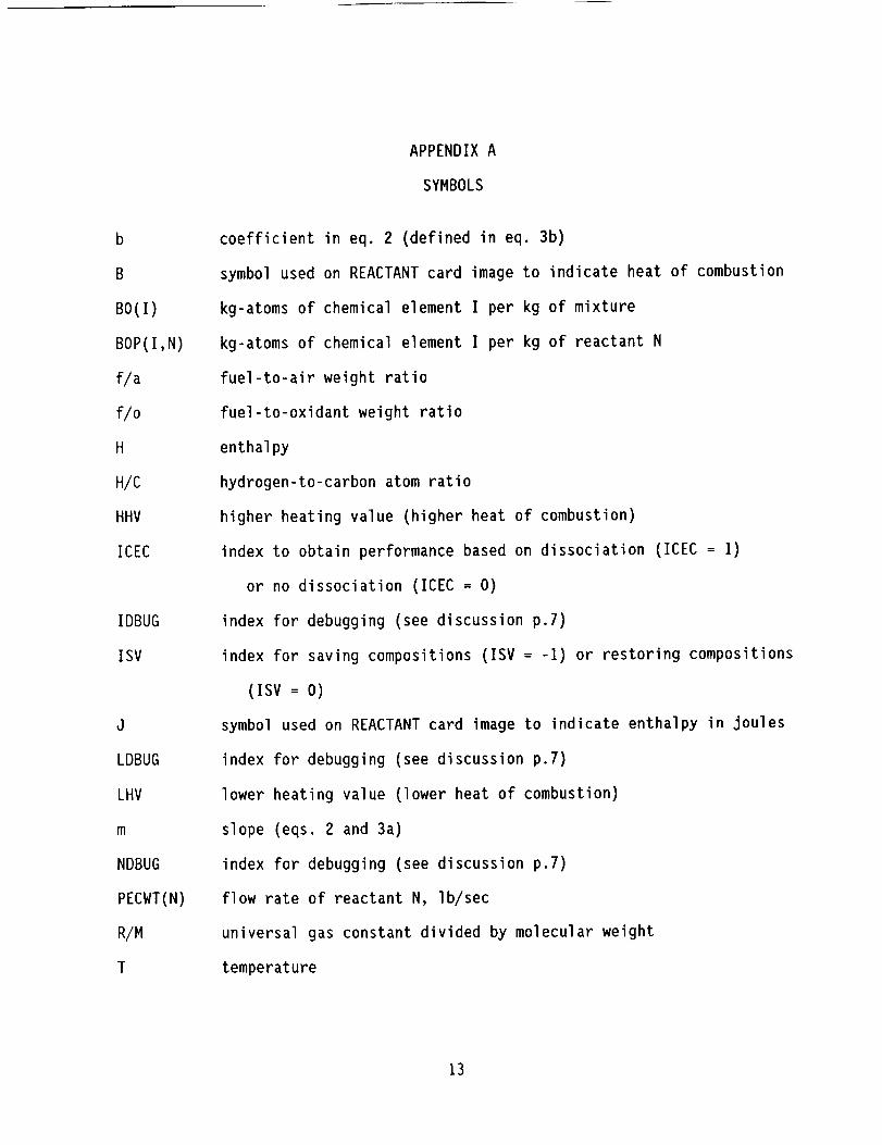
APPENDIX A
SYMBOLS
coefficient in eq. 2 (defined in eq. 3b)
symbol used on REACTANT card image to indicate heat of combustion
kg-atoms of chemical element I per kg of mixture
kg-atoms of chemical element I per kg of reactant N
fuel-to-air weight ratio
fuel-to-oxidant weight ratio
enthalpy
hydrogen-to-carbon atom ratio
higher heating value (higher heat of combustion)
index to obtain performance based on dissociation (ICEC = ])
or no dissociation (ICEC = O)
index for debugging (see discussion p.7)
index for saving compositions (ISV = -I) or restoring compositions
(ISV = O)
symbol used on REACTANT card image to indicate enthalpy in joules
index for debugging (see discussion p.7)
lower heating value (lower heat of combustion)
slope (eqs. 2 and 3a)
index for debugging (see discussion p.7)
flow rate of reactant N, Ib/sec
universal gas constant divided by molecular weight
temperature
13

WTREAC(N,J)flow rate of reactant N in flow station J, |b/sec
Ah difference betweenenthalpy of reactants and enthalpy of products,
eq. 1
&D namelist D
&INPT2 namelist INPT2
14

APPENDIXB
SAMPLEPROBLEMS
TESTCASE: MIXEDFLOWTURBOFANSANFORDNEW&D ICEC=I, LONG=F,NCODE=I,DRAW=T,NMODES=I,&END
REACTANTSN 1.5606 0 0.4198 AR .0098 100. 0.0 GC 0.5245 H 1.0000 100. -4628.066L
298.15298.15
0F
END&DMODE=I,XNUM=4HINLT,4HLPCI,4HSPLI,4HHPCI,4HMBRN,4HHPTI,4HMXRI,4HABRN,4HNOZI,4HNOZO,4HSECI,4HSECO,KONFIG(I,I)=4HINLT,I,0,2,0,SPEC(I,I)=IO0.O,O.,O.,O.,O.,O.,O.,0.,0.,0.,0.,18.00,KONFIG(I,2)=4HCOMP,2,0,3,0,SPEC(1,2)=I.60,O.,I,IO01,1,1002,1,1003,1,0.,0.,0.84,2.9,0.95,KONFIG(I,3)=4HSPLT,3,0,4,12,SPEC(I,3)=1.75,0.02,0.02,KONFIG(I,4)=4HCOMP,4,0,5,0,SPEC(I,4)=I.30,O.,I.,IO04,1,1005,I,1006,1,0.,0.,0.84,6.0,I,KONFIG(I,5)=4HDUCT,5,0,6,0,SPEC(I,5)=.05,0,O,3000.,.99,18300.,FARRAY(I,5)=2,1,KONFIG(I,6)=4HTURB,6,0,7,0,SPEC(I,6)=3.6,1.0,I,IO07,1,I,I,I,I,I,.90,5000,1,KONFIG(I,7)=4HMIXR,7,13,8,0,SPEC(I,7)=O.,O.,O.40,I.,O.,O.,KONFIG(I,B)=nHDUCT,B,O,g,o,SPEC(I,8)=.05,0,O,3600.,.g9,18300.,FARRAY(I,8)=2,1,KONFIG(1,9)=4HNOZZ,g,o,10,O,SPEC(1,9)=O.,O.98,0.,O.,.98,1.,1.,0.,I.,KONFIG(I,IO)=4HDUCT,12,0,13,0,SPEC(I,IO)=.05,0,O,O.,O.99,18300.,FARRAY(I,IO)=2,1,KONFIG(1,II)=4HSHFT,2,4,6,0,SPEC(I,11)=9*I.0,KONFIG(I,12)=4HCNTL,SPCNTL(I,12)=I,I,4HSTAP,8,2,0,O,KONFIG(1,13)=4HCNTL,SPCNTL(I,13)=1,4,4HSTAP,8,4,0,O,KONFIG(I,14)=4HCNTL,SPCNTL(I,14)=I,I1,4HDOUT,8,II,0,O,KONFIG(I,15)=4HCNTL,SPCNTL(I,15)=I,6,4HSTAP,8,6,0,O,KONFIG(1,16)=4HCNTL,SPCNTL(I,16)=I,3,4HDOUT,8,7,0,O,KONFIG(1,17)=4HCNTL,SPCNTL(I,17)=I,2,4HDOUT,5,2,50,O,&END&DSPEC(9,12)=I.0,SPEC(9,13)=I.0,SPEC(9,In)=I.0,SPEC(9,15)=I.0,SPEC(B,I)=.26,SPEC(g,I)=50,SPEC(6,1)=O,SPEC(9,16)=I.0,SPEC(9,17)=O.O,&END&DSPEC(5,I)=.6,SPEC(g,I)=IOOOO,&END&DSPEC(5,1)=.9,SPEC(9,1)=25000,&END&DSPEC(5,1)=I.2,SPEC(9,I)=32200,&END&DSPEC(5,1)=I.B,SPEC(9,1)=39500,&END&DSPEC(5,I)=I.8,SPEC(g,1)=46800,SPEC(4,5)=3400,&END&DSPEC(5,1)=2.0,SPEC(9,1)=50900,SPEC(4,5)=3600,&END&DSPEC(B,I)=2.B,SPEC(B,I)=55000,SPEC(4,5)=3800,SPEC(I,2)=2.0,&END
15

TESTCASE: SEPARATEFLOWTURBOFANSANFORDNEW&D ICEC=I, LONG=F,NCODE=I,DRAW=F,NMODES=I,&END
REACTANTSN 1.5606 0 0.4198 AR .0098 100. 0.0 GC 0.5245 H 1.0000 100. -4628.066L
298.]5298.15
0F
NAMELIST&INPT2 IDBUG=I,&END
END&DMODE=I,XNUM=4HINLT,4HLPCI,4HSPLI,4HHPCI,4HMBRN,4HHPTI,4HSBRN,4HLPTI,4HABRN,4HNOZI,4HNOZO,4HABRN,4HNOZI,4HNOZO,4HBLED,
0,2,0,SPEC(I,1)=I00.0,0.,0.,0.,0.,0.,0.,KONFIG(I,I)=4HINLT,I,0.,0.,0.,0.,18.00,KONFIG(I,2)=4HCOMP,2,1003,1,0.,0.,0.85,3.,KONFIG(I,3)=4HSPLT,3,KONFIG(I,4)=4HCOMP,4,0.84,6.,I,
KONFIG(I,5)=4HDUCT,5,FARRAY(I,5):2.,I.,KONFIG(I,6)=4HTURB,6,KONFIG(I,7)=4HDUCT,7,FARRAY(I,7)=2.,I.,KONFIG(I,8)=4HTURB,8,
1,KONFIG(I,g)=4HDUCT,9,FARRAY(I,9)=2.,I.,KONFIG(I,IO)=4HNOZZ,KONFIG(I,I])=4HDUCT,FARRAY(I,11)=2.,I.,KONFIG(I,12)=4HNOZZKONFIG(I,13)=4HSHFTKONFIG(I,In)=nHSHFTKONFIG(I,15):4HCNTLKONFIG(I,16)=4HCNTLKONFIG(I,17)=4HCNTLKONFIG(I,18)=4HCNTLKONFIG(I,]9)=4HCNTLKONFIG(I,20)=4HCNTL&END&DDRAW=F,SPEC(9,]5)
0,3,13,SPEC(1,2)=1.7,.001,1,1001,1,1002,1,I.,
0,4,12,SPEC(1,3):.63,0.02,0.02,
0,5,0,SPEC(1,4)=1.3,0.,I.,1004,1,1005,1,1006,1,0. ,0.,
0,6,0,SPEC(1,5)=.05,0,0,3200,.99,18300.,
0,7,0,SPEC(1,6)=3.3,0,1,I007,1,1008,1,1,I,1,.90,5000,I,
0,8,0,SPEC(1,7)=.05,0,0,3400.,.99,18300.,
15,9,0,SPEC(1,8)=1.6,1.0,I,1009,1,1010,I,1,1,I,.90,5000,
0,I0,0,SPEC(1,9)=.05,0,0,0.,.99,18300.,
10,0,11,0,SPEC(I,10)=0.,0.98,0.,0.,.98,1.,I.,0.,I.,
12,0,13,0,SPEC(1,11)=.05,0,0,0,.99,18300.,
13,0,14,0,SPEC(I,12)=O.,O.gB,O.,O.,O.9B,I.,I.,O.,I.,
2,8,0,0,SPEC(1,13)=9"I.0,
4,6,0,0,SPEC(1,14)=9"I.0,
SPCNTL(I,15)=I,I,4HSTAP,8,2,0,O,
SPCNTL(I,16)=I,4,4HSTAP,8,4,0,O,
SPCNTL(I,17)=I,6,4HSTAP,8,6,0,O,
SPCNTL(I,18)=1,8,4HSTAP,8,8,0,O,SPCNTL(1,I9)=I,3,4HDOUT,8,13,0,O,
SPCNTL(I,20)=l,14,4HDOUT,8,14,0,O,
=I,SPEC(9,16)=I,SPEC(9,17)=I,SPEC(9,18)=I,SPEC(9,19)=I,
SPEC(9,20)=l,SPEC(S,I)=.26,SPEC(9,1)=50,SPEC(6,1):O,&END
&D SPEC(B,I)=.6,SPEC(9,1)=IOOOO,&END
&D SPEC(5,1)=.9,SPEC(9,1)=25000,&END
&D SPEC(5,1)=I.2,SPEC(9,1)=32200,&END
&D SPEC(5,I)=I.5,SPEC(9,1)=39500,&END
&D SPEC(5,1)=I.8,SPEC(9,1)=46800,&END
&D SPEC(5,1)=2.0,SPEC(9,1)=509OO,&END&D SPEC(5,1)=2.5,SPEC(9,1)=55000,&END
&D SPEC(5,1)=3.0,SPEC(9,1)=58400,&END
16

TESTCASE: I-SPOOLTBE SANFORDNEW&D ICEC=I,NCOMP=9,NOSTAT=I],DRAW=T,NCODE=I,LONG=F,AMAC=F,&END
REACTANTSN 1.5606 0 0.4198 AR .0098 100.0 M 0.0 GC 0.5245 H 1.0000 100.0 M -4628.066L
298.15298.15
END&DMODE=I,XNUM=4HINLT,4HHPCI,4HDUCT,4HMBRN,4HHPTI,4HDUCT,4HABRN,4HNOZI,4HNOZO,4HBLED,4HBPAS,KONFIG(I,J)=4HINLT,I,0,2,0,SPEC(I,I)=0,4*O,O,O,O,.O000],2*O,O,O,IO0,KONFIG(I,2)=4HCOMP,2,0,3,JO,SPEC(I,2)=].3,.O0],I,IO04,],IO05,1,1006,1,0,0,.84,4,1.0,KONFIG(1,3)=4HDUCT,3,0,4,J1,SPEC(I,3)=8*O,.15,KONFIG(I,4)=4HDUCT,4,0,5,0,SPEC(I,4)=.0616,0,O,3000.,.99,18300.,FARRAY(I,4)=2,1,KONFIG(I,5)=4HTURB,5,JO,6,0,SPEC(I,5)=3.32,1,J,IO07,1,1008,],I,.6,.86,.90,5000,1,0,0,KONFIG(],6)=4HDUCT,6,Jl,7,0,SPEC(I,6)=7*0,1,J,KONFIG(J,7)=nHDUCT,7,0,B,O,SPEC(I,7)=3*O,O,.99,18300.,FARRAY(I,7)=2,1,KONFIG(I,8)=4HNOZZ,8,0,g,o,SPEC(I,8)=0,1,0,O,.985,J,I,0,],KONFIG(I,9)=4HSHFT,2,5,0,O,SPEC(I,9)=J,I,J,O,O,],I,KONFIG(I,IO)=4HCNTL,SPCNTL(J,IO)=I,2,4HSTAP,8,2,0,O,KONFIG(I,II)=4HCNTL,SPCNTL(I,11)=I,5,4HSTAP,8,5,0,O,KONFIG(I,12)=4HCNTL,SPCNTL(],I2)=14,1,4HDOUT,8,9,O,O,KONFIG(I,]3)=4HCNTL,SPCNTL(],I3)=1,9,4HDOUT,5,2,20,O,KONFIG(I,J4)=4HCNTL,SPCNTL(J,14)=9,3,4HDOUT,5,2,20,O,&END&DDRAW=F,SPEC(5,1)=.26,SPEC(6,1)=O,SPEC(9,1)=50,SPEC(g,10)=J,SPEC(9,]I)=I,SPEC(9,J2)=J,SPEC(9,14)=J,&END&DSPEC(5I)=.6,SPEC(g,I)=JOOOO,&END&DSPEC(5I)=.9,SPEC(B,J)=25000,&END&DSPEC(5I)=I.2,SPEC(g,J)=32200,&END&DSPEC(5I):I.5,SPEC(9,1):39500&DSPEC(5I):I.8,SPEC(9,1)=46800&DSPEC(5I)=2.0,SPEC(9,1)=50900&DSPEC(5I)=2.5,SPEC(9,1)=55000SPEC(B,3)=O,SPEC(B,14)=O,&END&DSPEC(5,1)=3.0,SPEC(9,1)=58400
,&END,&END,SPEC(4,4)=3100, &END
,&END
0F
17

ATRWITHHYDROGENTOTESTSANFORD'SNEWPROGRAM&D LONG=F,DRAW=T,ICEC=I,NCODE=-I,NCOMP=]3,NOSTAT=IO,&END
REACTANTSN 1.5606 O 0.4198 AR .0098 100.0 M 0.0 GC 1. H 4. ]00.0 -21390.L0 2. 100. -3]02. LC 1. H 4. 100.0 21500.G
298.]5 0111.66 F90.18 0298.15BF0.995
END&DMODE=],KONFIG(I,])=4HINLT,],O,2,0,SPEC(],I)=IO0,4*O,.97,2*O,.],2*0,14KONFIG(I,2)=4HCOMP,2,0,3,0,SPEC(],2)=I.6,0,1,1001,I,IO02,1,]O03,1,0,0,.85,2.0,1.,KONFIG(I,3)=4HSPLT,3,0,4,5,SPEC(I,3)=O.,O.,KONFIG(],4)=4HMIXR,4,10,7,0,SPEC(I,4)=O.,O.,O.25,.95,KONFIG(I,B)=nHGGEN,5,0,6,0,SPEC(I,5)=2960,.67184,600.,].644,FARRAY(1,5)=2,1,OARRAY(I,5)=3,1,KONFIG(I,6)=4HDUCT,7,0,8,0,SPEC(],6)=.05,0,O,-O.058,0.995,21500.,FARRAY(],6)=4,1,KONFIG(],7)=4HNOZZ,8,0,g,o,SPEC(],7)=0,1,0,O,.985,],I,0,I,KONFIG(],8)=4HTURB,6,0,10,O,SPEC(I,8)=3.6,0.,I,IO07.,],1008,1,1,0,1,.80,5000,1,KONFIG(I,9)=4HSHFT,2,8,0,O,SPEC(I,9)=9*I,KONFIG(I,IO)=4HCNTL,SPCNTL(I,]O)=I.0,1.0,4HSTAP,8.0,2.0,O.,.O,O.,O.,KONFIG(1,11)=4HCNTL,SPCNTL(I,11)=4.0,5.0,4HDOUT,8.0,4.0,O,O,O.,O.,KONFIG(1,12)=4HCNTL,SPCNTL(I,12)=3.0,5.0,4HSTAP,8.0,6.0,O.,.O,O.,O.,KONFIG(1,13)=4HCNTL,SPCNTL(I,13)=1.0,8.0,4HDOUT,8.0,9.O,O.,.O,O.,O.,KONFIG(I,]4)=nHCNTL,SPCNTL(I,]4)=I.O,g.O,4HDOUT,5.0,2.0,20.,.O,O.,O.,KONFIG(1,15)=4HCNTL,SPCNTL(1,15)=4.0,5.0,4HSTAP,2.0,10.O,28.510,O,O,O,XNUM=4HINLT,4HHPCI,4HHPCO,4HMIXP,4HWGAS,4HHPTI,4HMIXO,4HNOZI,4HNOZO,4HMIXS,&END&DDRAW=F,SPEC(g,IO)=I,SPEC(9,1])=I,SPEC(g,12)=I,SPEC(9,13)=I,SPEC(5,1)=.26,SPEC(9,1)=50,SPEC(6,1)=O,&END&DSPEC(5,1):.6,SPEC(9,])=IOOOO,&END&DSPEC(5,1)=.9,SPEC(9,1)=25000,&END&DSPEC(5,1)=I.2,SPEC(9,1)=32200,&END&DSPEC(5,1)=I.5,SPEC(g,1)=39500,&END&DSPEC(5,1)=I.8,SPEC(g,I)=46800,&END&DSPEC(5,1)=2.0,SPEC(9,1)=5ogoo,&END&DSPEC(5,I)=2.5,SPEC(g,I)=55000,&END&DSPEC(5,])=3.0,SPEC(9,])=58400SPEC(9,3)=O,SPEC(g,14)=O,&END&DSPEC(5,])=3.0,SPEC(g,I)=58400,&END
18
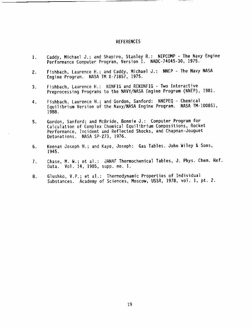
REFERENCES
I •
•
3,
4
,
•
.
•
Caddy, Michael J.; and Shapiro, Stanley R.: NEPCOMP - The Navy Engine
Performance Computer Program, Version I. NADC-74045-30, 1975.
Fishbach, Laurence H.; and Caddy, Michael J.: NNEP
Engine Program. NASA TM X-71857, 1975.
The Navy NASA
Fishbach, Laurence H.: KONFIG and REKONFIG Two Interactive
Preprocessing Programs to the NAVY/NASA Engine Program (NNEP), I981.
Fishbach, Laurence H.; and Gordon, Sanford: NNEPEQ
Equilibrium Version of the Navy/NASA Engine Program.1988.
Chemical
NASA TM-I00851,
Gordon, Sanford; and McBride, Bonnie J.: Computer Program for
Calculation of Complex Chemical Equilibrium Compositions, Rocket
Performance, Incident and Reflected Shocks, and Chapman-Jouguet
Detonations. NASA SP-273, 1976.
Keenan Joseph H.; and Kaye, Joseph: Gas Tables. John Wiley & Sons,1945.
Chase, M. W.; et al.: JANAF Thermochemical Tables, J. Phys. Chem. Ref.
Data. Vol. 14, 1985, supp. no. I.
Glushko, V.P.; et al.: Thermodynamic Properties of Individual
Substances. Academy of Sciences, Moscow, USSR, ]978, vol. 1, pt. 2.
19

TABLEI REACTANTSCARDIMAGE
Order Contents Format Columns
First
Any
Last
REACTANTS
Onecard for each reactant species(maximum24). Eachcard contains:
(i) Atomic symbols and formula numbers(maximum5 sets) a
(2) Enthalpy or heat of combustionb
(3) State: S, L, or G for solid,liquid, or gas, respectively
(4) Temperature associated withenthalpy in (2)
(5) Blank, J or B
(6) Combustionefficiency(default is 1.00)
Blank
3A4
5(A2,F7.5)
F9.5
AI
F7.5
AI
F8.5
1 to 9
I to 45
54 to 62
63
64 to 70
71
73 to 80
a. If zeros are put in columns 37 & 38, the program will automatically
calculate the enthalpy of the reactant at the specified temperature (4),
provided that the same species as the reactant is also in the thermodynamicdata set.
b. Enthalpy if column 71 is blank or J (Units are cal/g-mole if blank or
J/formula wt. if J). Heat of combustion in BTU/Ib if column 71 is B.
20

Table 2. - Values of ARG and Calculated Parameter in Function THERM
ID ARG
(Independent
parameter)
I enthalpy, BTU/Ib
2 temperature, °R
3 relative pressure ratio
4 temperature, °R
5 temperature, °R
6 fuel/air ratio
Value Calculated
(Dependent
parameter)
temperature, °R
relative pressure ratio
temperature, °R
enthalpy, BTU/Ib
specific heat ratio
R/M
(universal gas constant/
molecular weight)
Values of ARG and DUMMYP in Subroutine THERMETable 3.
ID ARG
enthalpy, BTU/Ib
temperature ratio
pressure ratio
temperature, °R
enthalpy, BTU/Ib
Mach no. (squared)
!
2*
3*
4,5,6
7*
8*
*Isentropic process.
DUMMYP
pressure, psi
pressure, psi
pressure, psi
pressure, psi
(not used)
(not used)
Assumes required values such as entropy and/or pressure
have already been stored for initial point.
21

Form ApprovedREPORT DOCUMENTATION PAGE OMB No. 0704o0188
Public reporting burden for this collec'llon of information is estimated to average 1 hour per response, including the time for reviewing instructions, searching exisling data sources,
gathering and maintaining the data needed, and completing and reviewing the collection of information. Send comments regarding this burden estimate or any other aspect of thi;.
collection of information, including suggestions for reducing this burden, to Washington Headquarters Services, Oireclorate for information Operations af_d Reporls, 1215, Jelferson
Davis Highway, Suile 1204, Arlington, VA 22202-4302. and to the Office of Management and Budget, Paperwork Reduction Project (0704-0188), Washington. DC 20503
1. AGENCY USE ONLY (Leave blank) 2. REPORT DATE 3. REPORT TYPE AND DATES COVERED
September 1991 Final Contractor Report
4. TITLE AND SUBTITLE 5. FUNDING NUMBERS
The NAVY/NASA Enghle Program (NNEP89)--Interfacing the Program
for the Calculation of Complex Chemical Equilibrium Compositions (CEC)
6. AUTHOR(S)
Sanford Gordon
7. PERFORMING ORGANIZATION NAME(S) AND ADDRESS(ES)
Sverdrup Technology, Inc.
Lewis Research Center Group
2001 Aerospace Parkway
Brook Park, Ohio 44142
9. SPONSORING/MONITORING AGENCY NAMES(S) AND ADDRESS(ES)
National Aeronautics and Space Administration
Lewis Research Center
Cleveland, Ohio 44135 - 3191
WU- 505 - 69 - 50
C-NAS3-24105
8. PERFORMING ORGANIZATION
REPORT NUMBER
None
10. SPONSORING]MONITORING
AGENCY REPORT NUMBER
NASA CR- 187208
11. SUPPLEMENTARY NOTES
Project Manager, C. Snyder, Aeropropulsion Analysis Office, NASA Lewis Research Center, (216) 977-7018.
Sanford Gordon, Sanford Gordon & Associates , Cleveland, Ohio, subcontractor to Sverdrup Technology, Inc.
12a. DISTRIBUTION/AVAILABILITY STATEMENT
Unclassified - Unlimited
Subject Category 07
12b. DISTRIBUTION CODE
13. ABSTRACT (Maximum 200 words)
The Navy/NASA Engine Program--NNEP, is a general computer program for calculating aircraft engine perfor-
mance. NNEP has been used extensively to calculate the design and off-design (matched) pertormance of a broad
range of turbine engines, ranging from subsonic turboprops to variable cycle engines for supersonic transports.
Recently, however, there has been increased interest in applications lbr which NNEP is not capable of simulating,
such as the use of altenmte fuels including cryogenic fuels and the inclusion of chemical dissociation effects at high
temperatures. To overcome these limitations, NNEP has now been extended by including a general chemical
equilibrium method. This permits consideration of any propellant system and the calculation of performance with
dissociation effects. The new extended program is referred to as NNEP89.
14. SUBJECT TERMS
Cotnputer programs; Engine performance; Chemical equilibrium; Turbine engines;
Performance prediction
17. SECURITY CLASSIFICATION
OF REPORT
Unclassified
NSN 7540-01-280-5500
18. SECURITY CLASSIFICATION
OF THIS PAGE
Unclassified
19. SECURITY CLASSIFICATION
OF ABSTRACT
Unclassified
15. NUMBER OF PAGES
24
16. PRICE CODE
A03
20. LIMITATION OF ABSTRACT
Standard Form 298 (Rev. 2-89)
Prescribed by ANSI Std. Z39-18
298-102


National Aeronautics and
Space Administration
Lewis Research Center
Cleveland, Ohio 44135
Official Bu=dnelm
Penllty for Private Use $300
FOURTH CLA88 MAIL
ADDRESS CORRECTION REQUESTEO
IIIIII
Poslage and Fees Pa_d
Nal=onal Aeronauhcs and
Space Admmlslralton
NASA 451
i I