THE NATIONAL SHIPBUILDING RESEARCH PROGRAMManish Gupta,Naval Architect/Ocean Engineer Paul...
203
SHIP PRODUCTION COMMITTEE FACILITIES AND ENVIRONMENTAL EFFECTS SURFACE PREPARATION AND COATINGS DESIGN/PRODUCTION INTEGRATION HUMAN RESOURCE INNOVATION MARINE INDUSTRY STANDARDS WELDING INDUSTRIAL ENGINEERING EDUCATION AND TRAINING THE NATIONAL SHIPBUILDING RESEARCH PROGRAM June 1996 NSRP 0465 U.S. DEPARTMENT OF THE NAVY CARDEROCK DIVISION, NAVAL SURFACE WARFARE CENTER in cooperation with Newport News Shipbuilding A Common Sense Design Manual for Producibility of Hull Foundations
Transcript of THE NATIONAL SHIPBUILDING RESEARCH PROGRAMManish Gupta,Naval Architect/Ocean Engineer Paul...
SHIP PRODUCTION COMMITTEEFACILITIES AND ENVIRONMENTAL EFFECTSSURFACE PREPARATION AND COATINGSDESIGN/PRODUCTION INTEGRATIONHUMAN RESOURCE INNOVATIONMARINE INDUSTRY STANDARDSWELDINGINDUSTRIAL ENGINEERINGEDUCATION AND TRAINING
THE NATIONALSHIPBUILDINGRESEARCHPROGRAM
June 1996NSRP 0465
U.S. DEPARTMENT OF THE NAVYCARDEROCK DIVISION,NAVAL SURFACE WARFARE CENTER
in cooperation with
Newport News Shipbuilding
A Common Sense Design Manual forProducibility of Hull Foundations
Report Documentation Page Form ApprovedOMB No. 0704-0188
Public reporting burden for the collection of information is estimated to average 1 hour per response, including the time for reviewing instructions, searching existing data sources, gathering andmaintaining the data needed, and completing and reviewing the collection of information. Send comments regarding this burden estimate or any other aspect of this collection of information,including suggestions for reducing this burden, to Washington Headquarters Services, Directorate for Information Operations and Reports, 1215 Jefferson Davis Highway, Suite 1204, ArlingtonVA 22202-4302. Respondents should be aware that notwithstanding any other provision of law, no person shall be subject to a penalty for failing to comply with a collection of information if itdoes not display a currently valid OMB control number.
1. REPORT DATE JUN 1996
2. REPORT TYPE N/A
3. DATES COVERED -
4. TITLE AND SUBTITLE The National Shipbuilding Research Program, A Common Sense DesignManual for Producibility of Hull Foundations
5a. CONTRACT NUMBER
5b. GRANT NUMBER
5c. PROGRAM ELEMENT NUMBER
6. AUTHOR(S) 5d. PROJECT NUMBER
5e. TASK NUMBER
5f. WORK UNIT NUMBER
7. PERFORMING ORGANIZATION NAME(S) AND ADDRESS(ES) Naval Surface Warfare Center CD Code 2230-Design Integration TowerBldg 192, Room 128 9500 MacArthur Blvd Bethesda, MD 20817-5700
8. PERFORMING ORGANIZATIONREPORT NUMBER
9. SPONSORING/MONITORING AGENCY NAME(S) AND ADDRESS(ES) 10. SPONSOR/MONITOR’S ACRONYM(S)
11. SPONSOR/MONITOR’S REPORT NUMBER(S)
12. DISTRIBUTION/AVAILABILITY STATEMENT Approved for public release, distribution unlimited
13. SUPPLEMENTARY NOTES
14. ABSTRACT
15. SUBJECT TERMS
16. SECURITY CLASSIFICATION OF: 17. LIMITATION OF ABSTRACT
SAR
18. NUMBEROF PAGES
202
19a. NAME OFRESPONSIBLE PERSON
a. REPORT unclassified
b. ABSTRACT unclassified
c. THIS PAGE unclassified
Standard Form 298 (Rev. 8-98) Prescribed by ANSI Std Z39-18
DISCLAIMER
These reports were prepared as an account of government-sponsored work. Neither theUnited States, nor the United States Navy, nor any person acting on behalf of the UnitedStates Navy (A) makes any warranty or representation, expressed or implied, with respectto the accuracy, completeness or usefulness of the information contained in this report/manual, or that the use of any information, apparatus, method, or process disclosed in thisreport may not infringe privately owned rights; or (B) assumes any liabilities with respect tothe use of or for damages resulting from the use of any information, apparatus, method, orprocess disclosed in the report. As used in the above, “Persons acting on behalf of theUnited States Navy” includes any employee, contractor, or subcontractor to the contractorof the United States Navy to the extent that such employee, contractor, or subcontractor tothe contractor prepares, handles, or distributes, or provides access to any informationpursuant to his employment or contract or subcontract to the contractor with the UnitedStates Navy. ANY POSSIBLE IMPLIED WARRANTIES OF MERCHANTABILITY AND/ORFITNESS FOR PURPOSE ARE SPECIFICALLY DISCLAIMED.
N COMMITTEE June, 1996NSRP 0466
NMENTAL EFFECTSON AND COATINGSON INTEGRATIONE INNOVATIONY STANDARDSNGGINEERINGION
THE NATIONALSHIPBUILDINGRESEARCHPROGRAM
A Common Sense Design Manual ForProducibility of Hull Foundations
U. S. DEPARTMENT OF THE NAVYCARDEROCK DIVISION, NAVAL SURFACEWARFARE CENTER
in cooperation with
Newport News Shipbuilding
* * *
A COMMON SENSE
DESIGN MANUAL
FOR PRODUCIBILITY OF
HULL
125North
FOUNDATIONS* * *Prepared by
VIBTECH, Inc.Steamboat AvenueKingstown, RI 02852(401) 294-1590
Authors
John J. Hopkinson, PresidentManish Gupta, Naval Architect/Ocean Engineer
Paul Sefcsik, Mechanical EngineerGeoff Rivinius, Sr. Naval Architect
For
PANEL SP-4DESIGN/PRODUCTION INTEGRATION
Under the
SHIPBUILDING RESEARCH
* * *
MAY 1996
A COMMON SENSE DESIGN MANUALFOR PRODUCIBILITY OF HULL FOUNDATIONS
Contents
Executive Summary
Acknowledgment
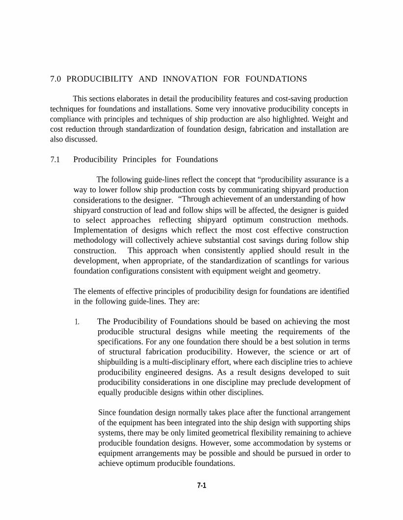
1. Purpose
2. General Scope
3. General Approach
3:1 Practical and Pragmatic Approach3.2 Producibility Initiatives3.3 Weight and Cost Reduction Initiatives3.4 Integrated Engineering and Design Approach
4. Foundation Design
4.1 Traditional Design Practice4.2 Progressive Design Practice
5. Production Process
5.1 Primary Work Centers5.2 Zone Outfit5 . 3 Pre-Outfit Hull Construction
6 . Producibility Principles for Ship Construction
4-1
5-1
6-1
6.1 Production Principles6.2 Production Techniques6.3 Design Consideration6.4 Benefits to Production
7. Producibility and Innovation for Foundations
7.1 Producibility Principles for Foundations7.2 Innovative Producibility Concepts7.3 Foundation Integration with Hull Construction7.4 Foundation Standards and Cost Reduction
8. Technical Approach
7-1
8-1
8.1 Criteria, Requirements and Specifications8.2 Innovative Design, Analysis and Testing Validation8.3 Design Methodology
9. Foundation Design Guide for Standard Foundation Types 9-1
9.1 Standard Family of Foundation Types9.2 Typical Scantlings for Standard Foundations9:3 Typical Configurations & Scantlings for Foundation Method Mount9.4 Typical Foundations Using Stud Equipment Mounting
AppendicesA. Design Data Table Calculation MethodologyB. Recommendations for Future Foundation Design StudyC. Q & A Review of Various Shipyard ResponsesD. Bibliography
AlB1ClD1
i i
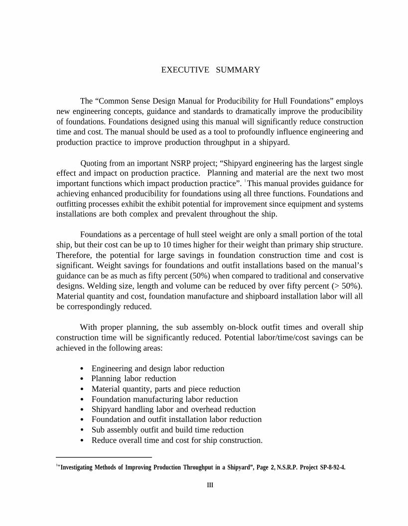
EXECUTIVE SUMMARY
The “Common Sense Design Manual for Producibility for Hull Foundations” employsnew engineering concepts, guidance and standards to dramatically improve the producibilityof foundations. Foundations designed using this manual will significantly reduce constructiontime and cost. The manual should be used as a tool to profoundly influence engineering andproduction practice to improve production throughput in a shipyard.
Quoting from an important NSRP project; “Shipyard engineering has the largest singleeffect and impact on production practice. Planning and material are the next two mostimportant functions which impact production practice”. 1 This manual provides guidance forachieving enhanced producibility for foundations using all three functions. Foundations andoutfitting processes exhibit the exhibit potential for improvement since equipment and systemsinstallations are both complex and prevalent throughout the ship.
Foundations as a percentage of hull steel weight are only a small portion of the totalship, but their cost can be up to 10 times higher for their weight than primary ship structure.Therefore, the potential for large savings in foundation construction time and cost issignificant. Weight savings for foundations and outfit installations based on the manual’sguidance can be as much as fifty percent (50%) when compared to traditional and conservativedesigns. Welding size, length and volume can be reduced by over fifty percent (> 50%).Material quantity and cost, foundation manufacture and shipboard installation labor will allbe correspondingly reduced.
With proper planning, the sub assembly on-block outfit times and overall shipconstruction time will be significantly reduced. Potential labor/time/cost savings can beachieved in the following areas:
●
●
●
●
●
●
●
●
Engineering and design labor reductionPlanning labor reductionMaterial quantity, parts and piece reductionFoundation manufacturing labor reductionShipyard handling labor and overhead reductionFoundation and outfit installation labor reductionSub assembly outfit and build time reductionReduce overall time and cost for ship construction.
1"Investigating Methods of Improving Production Throughput in a Shipyard”, Page 2, N.S.R.P. Project SP-8-92-4.
III
Our industryshipyard culture is
EXECUTIVE SUMMARY (cont.)
has demonstrated a persistent resistance to change. Our industriallocked in tradition and organizational inflexibility that tends to
institutionalize design practice. Our internal shipyard procedures instruct the engineer anddesigner to use previous ship designs as guidance for new construction. As a result most of theshipyard practices in our country, including foundation design, are similar. There seems to beno one or any entity that can or is willing to break the mold. As a result, our engineering anddesign groups tend to produce the same costly designs ship after ship, program after program.There seems to be no escape from this costly conundrum.
The time is ripe for technology breakthrough ideas. New improved shipyard processeswill come from the auto, airline or the computer industry. The guidance manual presentedherein is viewed as a first step to emulate more efficient assembly practices used in otherindustries. A process of continuing improvement should be supported by company executiveleadership to ensure that the goal for process improvement is not thwarted by theorganization’s natural resistance to change.
This manual incorporates designs based on an innovative effort to achieve producibilityand construction cost savings in foundations that was started in the early 1980’s. Thisinnovative effort led to the development of a family of standard foundation designs based onsimple geometries, and quick and easy installation methods. The standardized designs,illustrated in this manual, offer large savings in the time and cost for construction andinstallation aboard ship. Other guidance provides standard configurations and scantlings fortypical mounting methods that can be used for both equipment and systems installations.
The identification of important and relevant processes as they affect foundationproducibility and production planning are provided to guide the designer to achieve“production friendly” designs.
Technical requirements, performance criteria and specifications are addressed in themanual. Design and engineering approaches using first principles engineering and testing tovalidate innovative designs are outlined in the manual to encourage development of a strategyand means to achieve cost effective foundation and outfit design. Design methods are oulinedto help guide the designer to select foundations from standardized designs.
iv
ACKNOWLEDGMENT
This project was funded by the National Shipbuilding Research Program,Design/Production Panel (SP-4), chaired by Ronn E. Besselievre of Ingalls Shipbuilding. TheSP-4 Panel is one of the Ship Production Committee Panels of the Society of Naval Architectsand Marine Engineers, which were established with the purpose of improving U.S. shipbuildingperformance.
An extensive survey was conducted on the principles and practices of foundation designand production with several shipyards, and their feedback and recommendations are includedin this report. The authors acknowledge and appreciate the interest and participation of thefollowing shipyards: Avondale Shipyards; Bath Iron Work, Ingalls Shipbuilding; McDermottShipbuilding National Steel & Shipbuilding Company Newport News Shipbuilding.
The authors appreciate the permission to include figure 5.1 from Laurent C. Deschampsof SPAR Inc., MD.
The success of this project was accomplished through the efforts of many VIBTECHstaff. The authors would like to extend special thanks to Eric M. Jacobsen; Spencer L.Johnson; Sandra J. Ducharme; Keith C. Morrison and Judson B. Broome for their valuablecontribution.
Title A COMMON SENSE DESIGN MANUALFOR PRODUCIBILITY OF HULL FOUNDATIONS
1.0 PURPOSE
The purpose of this design manual is to provide information and guidance, and outlineengineering methodology for optimum design of foundations for either commercial ship ornaval combatants, with effectively integrating all design requirements.
1-1
2.0 GENERAL SCOPE
It is necessary to develop an engineering approach to foundation design thatencompasses all the requirements yet results in a practical engineering methodology. The designmanual is helpful in formulating the relevant requirements for design and analysis andcontrolling the engineering content of drawings to ensure that foundations meet
● Structural adequacy● Vibration limit● Acoustical level limit● Producibility criteria• Weight & Cost effectiveness● Maintenance requirement
The manual helps in the design process for the foundations, adequate to resist ship’smotions acceleration and other environmental loading for all ships and shock accelerations incase of combatants. Equipment function, shipboard environment survivability, and othermission requirements affect the design and engineering factors that must be considered for eachfoundation installation. Manufacturing techniques, construction and installation requirementsmust be adjudicated properly to achieve effective foundations. It is essential to identify,integrate and prioritized the requirements as they apply to each foundation. It is importantthat the guidance be provided to facilitate the engineering drawing schedule and ultimately theship construction schedule. In order for the guide to be practical, unnecessary engineering anddesign refinements must be minimized The scope of the engineering design work must be,limited for the following reasons
● The generalized methods (statistical approximations) used to develop shockinputs and engineering methodology used in shock, vibration and noiseengineering logically preclude unnecessary and overly sophisticated engineeringmethodology.
● A generalized seaway and environmental loading used with appropriate safetymargin makes detail engineering for every individual foundation unnecessary.
● The engineering and design of foundations must be done in a timely fashion inorder to complement the ship construction process which is organized to ensuredelivery of the ship on time, with the quality required within estimated costs.
2-1

The steadily increasing cost of material and labor on the construction of naval vesselsdictates that shipboard foundations be lighter and of simple design. The most costly processin hull structure fabrication is the cutting, fit-up, and welding operations necessary forfoundation construction. Foundation designs that minimize cutting, fitting and welding and reduce the requirement for jigs and fixtures will result in a significant reduction of labor man-hours.
2-2
3.0 GENERAL APPROACH
The general approach taken in this design manual is to employ a practical andpragmatic approach to foundation design. Use producibility features, weight and costreductions techniques and follow an integrated engineering and design approach to foundationdesign.
3.1 Practical and Pragmatic Approach
The foundation design team should understand and be committed to designinglightweight producible foundations (LWPF) and the organizational setup should bestructured to achieve LWPF. The underlying idea is to design and fabricatefoundations/system installations less costly to manufacture and install. The shipyardengineering, design arid production units should be tasked to implement cost savingsdesigns.
A practical and long-term approach would be to address critical technology,perform design engineering analysis and testing validation, apply innovativeproducibility and standardization concepts, apply production engineering principles tofoundation design, incorporate design methodology which expedites analyses inproduction mode, improve foundation integration with the hull, accelerate foundationconstruction installation, and employ technology and innovation for continuousimprovement.
3.2 Producibility Initiatives
Production oriented de-sign is an important initiative to be undertaken whenimplementing ship specifications and a practical constraint of the design. This manualreflects the concept that “producibility initiatives are a way to lower ship productioncosts by communicating shipyard production considerations to the designer.” Throughachievement of an understanding of how shipyard construction of lead and/or followships will be affected, the designer is guided to select approaches reflecting shipyardoptimum construction methods. Implementation of designs which reflect the most costeffective construction methodology will collectively achieve substantial cost savingsduring ship construction. This approach when consistently applied should result in thedevelopment, when appropriate, of the standardization of scantlings for variousfoundation configurations consistent with equipment weight and geometry.
3-1
3.3 Weight and Cost Reduction Initiatives
The development of light weight designs consistent with other requirements is needed in order to help meet ship displacement targets required to satisfy the specificship’s naval architectural limits. From the weight information databases of various classships its apparent that the foundations are a small percentage of the overall steel weightbut the relative cost is very high because the foundation design, fabrication andinstallation processes are currently not standardized and therefore not processcontrolled and neither production oriented.
It is important to save weight since weight saving will result in cost saving. Therecan be a significant potential for cost reduction, if an aggressive policy of foundationweight reduction is pursued combined with a producibility initiative to reduce the laborcontent of the fabrication and installation of foundations.
3.4 Integrated Engineering and Design Approach
The foundation design manual is developed to place constraints on the engineerand designer to develop typical foundations using an integrated engineering and designmethodology. However, an engineering process is never really complete, sinceimprovements can always be made in both production and engineering methodology.It is always desirable to reduce weight, eliminate pieces and reduce welding. It is alsoimportant to improve on the foundation engineering methodology, to reduceengineering time and develop new engineering shortcuts. The integrated designapproach should be regarded as a starting point upon which subsequent improvementcan be made. This procedure should be updated to reflect such improvements anddesign development.
The design manual provides the engineering design methodology required toachieve adequate foundation designs in a timely reamer. The methodology is brokendown into three sections. Technical Approach, Section 8.0 describes the criteria,requirements and specifications; and the design methodology. Producibility andInnovation for Foundations, Section 7.0 gives producibility and cost reduction guidanceto facilitate expediting production and to improve standardization in design.Foundation Design Guide for Standard Foundation Types, Section 9.0 provides a seriesof tables, tips and view-graphs to aid the design process towards standard designs.Appendix A describes the analysis methodology and criteria & specifications used toobtain the design data table values of Section 9.0.
3-2
4.0 FOUNDATION DESIGN
The design of ships, ship structures and foundations has followed an evolutionary path,steeped in tradition and qualitative design practices that are collectively known as “principlesof good sound ship construction practice”. his practice generally resulted in ships thatperformed reasonably well for the purpose intended, even though the engineering basis for theperformance was not well understood. While this technology has been elaborated on in thegeneral and detail specifications for ships there is no consistent way in which it has beeninterpreted or applied.
Traditional foundation designs are characterized by robust scantlings with substantialreinforcements that are costly and require significant time to manufacture and install. Thesedesigns have had a tendency to be based on past practice since there has been little guidance orinformation provided on acceptable alternative design approaches. The cost per unit weightof foundations in naval surface ships is approximately ten times greater than the cost ofprimary hull structure. The time required for foundation construction and installation processsignificantly affects the overall construction schedule. Traditional design practice andconservative interpretation of the ships specifications has tended to inhibit changes to improvefoundation design to be more cost effective.
With the advent of more rational and cost effective means to analyze and test theperformance of ships structures and foundations, significant cost reductions can be achievedwhile maintaining reliable and safe performance of both ship structure and foundations. Costand schedule benefit can be achieved for both commercial ships and naval vessels, although thefoundations for naval vessels have more stringent performance requirements. However, bothcommercial and naval vessel foundation designs will benefit greatly by subjecting foundationdesigns to testing as well as analysis, since the analysis methods employed are very conservativeand don’t either, reflect the dynamic loads imposed on the foundations or accurately portraythe response mechanisms that inherently exist in the ship and foundation structure.
4.1 Traditional Design Practice
The traditional relationship which has been established between the drafting andengineering design functions for foundations has proven to be very inefficient. Thisapproach is likely the result of a lack of visibility and appreciation for the adverseimpact foundation design has had and continues to have on the cost of shipconstruction. Although foundations represent only about 10% of the steel weight ofNavy ships, they represent 50% of the steel construction costs. While foundations incommericial ships represent a smaller portion of steel weight, their absolute numbersremain significant.
4-1
Traditionally, draftsmen were tasked with the design of foundations. Thesedraftsmen/designers invested many man-hours in drawing foundations based onprevious designs. This sequential design process developed from the “apprenticeship”heritage of shipbuilding, when designers/draftsmen had years of production experienceprior to being tasked with developing a design. This Sequential design paradigm workedwell for many years, particularly for commercial ships, as long as designers had theknowledge to perform the job.
As requirements became increasingly more complex and the shipbuildingindustry became more competitive, with margins on labor hours and throughputdetermining the winners and losers in a poor economic climate, it has become importantto develop efficient and cost effective designs. The sequential design process is notsuited to effective systems engineering which requires the integration and synergy ofmany fields and requirements. The designs which these draftsmen based their work ondid not incorporate new knowledge and technology regarding producibility. Engineersplayed a small part, merely approving designs with minimum changes, since any changewould require drawings to be redone and confusion would ensue. Engineers werelargely regarded as necessary to satisfy a legal requirement, rather than needed as anintegral part of the design process, even though the time had come when systems neededto be engineered rather than merely drawn up. As a result, optimum scantlings andproducibility concepts were never introduced into this costly group of ship structure,’although overtime considerable attention was being given to primary hull structure dueto its greater visibility (failures during and immediately following World War II) andstrides in hull design for greater performance. This draftsmen-driven design approachis still prevalent in the design community today, and producibility as a drivingconsideration is not yet fully entrenched in our industry’s corporate culture. Theresults of this design approach are heavy, over-designed foundations which are veryexpensive to construct.
The roles of the drafting and engineering functions in the sequential designregime can be summarized as follows:
● Draftsmen developed a systems integrated foundation design and final drawing
• Draftsmen extrapolated new designs from similar previous ship designs with abest guess at scantlings
4-2
ENGINEERS ROLE
● Engineers validated scantlings developed by draftsmen
● No requirement to stress optimize foundations
● Engineers approved designs with minimal scantling changes, since drawings andbudget were almost expended
● Engineers “rubber stamped” those designs which met specifications even ifgrossly over designed.
Figure 4.1 illustrates the traditional sequential approach. This is symptomaticof the traditional sequential design and engineering approach to the overall ship design,and is not limited to foundations alone. In this traditional sequential engineeringmodel, by the time engineering reviews and calculations are made, it is often too late toprovide feedback to those functions that are responsible for locking in decisions whichdrive the construction costs. Production planners are relegated to developing plans forbuilding that which has already been designed. Feedback from these producibilityexperts is rarely incorporated into the design. This system had worked during theearlier days of ship design and construction, when those responsible for the design wereexperienced and accomplished shipwrights, knowledgeable in ship production, with fewstringent requirements to consider. Today, to large extent, a few key decisions made “ina vacuum” early on in the project lock in nearly all future costs.
Recognizing that the shipyard is generally not in control of wage rates andmaterial costs, but is in control of labor hours and throughput rate, there is an incentiveto incorporate producibility and build strategy considerations early into the designphase. With properly sequenced engineering and drafting efforts significantMwprovements in design to cost of foundations can be made with more efficient use ofbudgeted design/engineering time and cost.
4-3
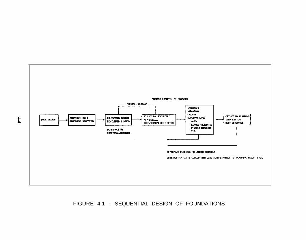
FIGURE 4.1 - SEQUENTIAL DESIGN OF FOUNDATIONS
4.2 Progressive Design Practice
The function of drafting, design and engineering must take on anew relationshipif producibility and build strategy considerations are to be incorporated early in theinitial ship design phases.
This new relationship requires the following:
● Draftsmen first develop sketches identifying systems environment andfoundation development constraints.
● Experienced and well trained designers and engineers, with the aid of expertsystems such as foundation data bases and extensive producibility guidelines,develop producibility oriented foundation concepts within the foundationenvironment space.
● Engineers fully develop foundation designs governed by the relevant criteria,such as shock, vibration, ship environment loading and fatigue.
● Draftsmen develop final drawings once engineering definition of foundationscantlings and producibility considerations/build strategies are complete.
This reordering of design functions, which can be referred to as a parallel designor concurrent engineering permits the major drafting effort to be expended after theoptimum foundation design has been achieved, maximizesproducibility and minimizesany major backfix efforts. In this process, engineering drives the design, constantlyproviding feedback and lessons learned to the expert systems. which serve as aknowledge base. In this way, the ship design team will continuously improve its designprocesses and products. The parallel approach to engineering is one of the keys toachieving the goal of parallel construction, significantly reducing time to delivery.
A vast quantity of data regarding equipment and foundation dimensions,scantlings and weights exists for a variety of ships and applications. Experience withand ability to utilize these statistics has permitted the development of a system forcharacterizing foundations into standard types. A library of standard baseline designshas been developed, which incorporate design principles for low cost and light weightstructural systems that can be engineered for a variety of applications. By performingparametric analysis, in which key variables are varied to determine a design’s sensitivityto these variables, a baseline design can be applied to an entire class of situations ratherthan a single application. Armed With this information essentially an expert system for
4-5
foundation design, structural engineers may integrate the available information, refineand optimize the deign and constantly feed new knowledge and lessons learned backinto the expert system. After a final, optimum, design has been established, thedrawings can be made and work packages developed. Figure 4.2 illustrates the notionalParallel Design approach which facilitates producibility and provides the shipyard witha more rigorous means of estimating costs and work content through the consistentapplication of known processes, procedures and systems in an efficient and cost efficientmanner.
4 - 6
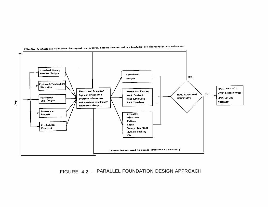
FIGURE 4.2 - PARALLEL FOUNDATION DESIGN APPROACH
5.0 PRODUCTION PROCESS
Production processes employed in the United States vary significantly from shipyardto shipyard, especially between those engaged in Naval work and those engaged in commercialwork. A simple characterization of shipyard production processes employed would not dojustice. Tradition, workload, capitalization, and business focus affect each shipyard’s marketposition and business strategy and hence their strategy and means of production.
Ship building has evolved from construction of hull steel and outfitting by ship fittersand skilled craftsmen on the building ways to modular construction where units are fabricatedfrom sub-assemblies and joined together in a graving dock or launching ways. The traditionalsub-assemblies are outfitted to the maximum extent practicable before the units are fitted to amain erection block. On block work completes the outfitting during block erection prior tolaunch.
Competitive shipbuilding is fostered by ensuring that designers and engineers are awareof the primary shipyard work centers and how they are related in an integrated shipbuildingproduction process. Design and engineering can then be more effective in ensuring thatfoundation, equipment and outfit items are manufactured, installed, and pre-outfitted, in theship in the right sequence and time in order to lower overall ship construction costs and reducethe ship construction schedule. Nevertheless, there are many constraints which may tend toinhibit pre-outfitting, such as lack of timely design information, that will require such items tobe installed later in the zone outfit stage of construction. The shipyard administration must doeverything possible to change methods of ship construction that result in a high ratio of laborto material costs in order to be globally competitive.
5.1 Primary Work Centers
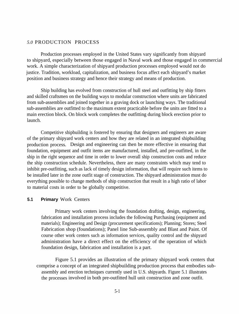
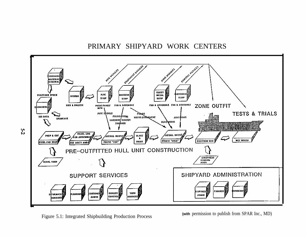
Primary work centers involving the foundation drafting, design, engineering,fabrication and installation process includes the following Purchasing (equipment andmaterials); Engineering and Design (procurement specifications); Planning; Stores; SteelFabrication shop (foundations); Panel line Sub-assembly and Blast and Paint. Ofcourse other work centers such as information services, quality control and the shipyardadministration have a direct effect on the efficiency of the operation of whichfoundation design, fabrication and installation is a part.
Figure 5.1 provides an illustration of the primary shipyard work centers that comprise a concept of an integrated shipbuilding production process that embodies sub-
assembly and erection techniques currently used in U.S. shipyards. Figure 5.1 illustratesthe processes involved in both pre-outfitted hull unit construction and zone outfit.
5-1
PRIMARY SHIPYARD WORK CENTERS
1,
Figure 5.1: Integrated Shipbuilding Production Process (with permission to publish from SPAR Inc., MD)
Pre-outfitting is the installation of non-structural items (including foundations)during all production stages up to erection. Such work on the post-erection period iscalled outfitting. In general, early pre-outfitting lowers cost. Of importance is the splitout of work during the “hot” prefit stage compared to the “cold” prefit stage ofconstruction. Where completely finished products can be installed subsequent to “blastand paint”, significant cost savings can be achieved by avoiding rework, painting andrepainting of affected items.
5.2 Zone Outfit
Build strategies using modular hull construction methods will reduce shipyardcosts with properly developed zone outfitting methods. As indicated in Section 5.1, pre-outfitting of units will generally result in lower costs. However, where pre-outfitting cannot be achieved, then cost effective means for accomplishing zone outfit must bedeveloped. Constraints that affect the amount of pre-outfittng include
● Lack of timely design information (lead ship)
● Erection weight
● Installation and trade sequences
● Protection of certain equipment from damage during construction
● Systems crossing unit boundaries
● Technological state-of-the-art, such as special coatings
General guidance for the design of ship systems and components, (orfoundations) in way of unit or subunit breaks is as follows:
1)2)3)4)5)6)
7)
Avoid system runs in way of unit/sub-unit breaksMinimize system runs crossing the unit/sub-unit breaksAvoid placing equipment (hence foundations) straddling unit breaksAvoid placing bulkheads at the unit/sub-unit breaksAvoid supporting systems from two different units or sub-unitsWhen systems run close to unit breaks leave room to allow access for welding andother fabrication techniquesPay attention to horizontal breaks as well as vertical breaks
5-3
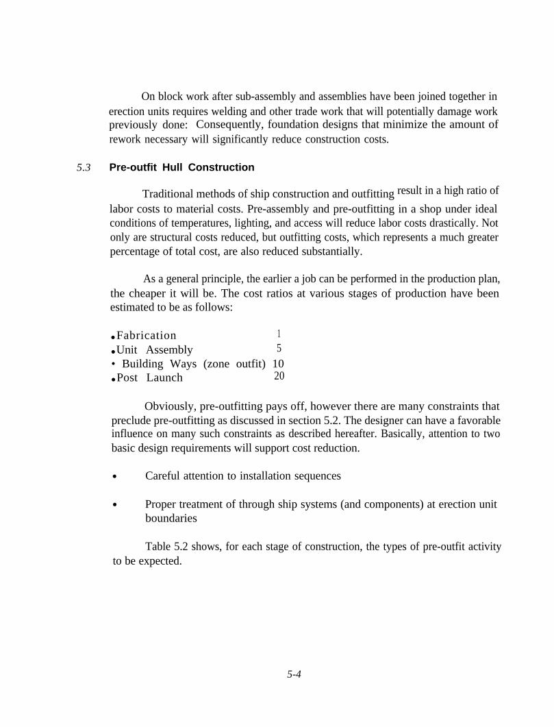
On block work after sub-assembly and assemblies have been joined together inerection units requires welding and other trade work that will potentially damage workpreviously done: Consequently, foundation designs that minimize the amount ofrework necessary will significantly reduce construction costs.
5.3 Pre-outfit Hull Construction
Traditional methods of ship construction and outfittinglabor costs to material costs. Pre-assembly and pre-outfitting in a shop under idealconditions of temperatures, lighting, and access will reduce labor costs drastically. Notonly are structural costs reduced, but outfitting costs, which represents a much greaterpercentage of total cost, are also reduced substantially.
result in a high ratio of
As a general principle, the earlier a job can be performed in the production plan,the cheaper it will be. The cost ratios at various stages of production have beenestimated to be as follows:
● Fabrication 1● Unit Assembly 5• Building Ways (zone outfit) 10● Post Launch 20
Obviously, pre-outfitting pays off, however there are many constraints thatpreclude pre-outfitting as discussed in section 5.2. The designer can have a favorableinfluence on many such constraints as described hereafter. Basically, attention to twobasic design requirements will support cost reduction.
● Careful attention to installation sequences
● Proper treatment of through ship systems (and components) at erection unitboundaries
Table 5.2 shows, for each stage of construction, the types of pre-outfit activityto be expected.
5-4
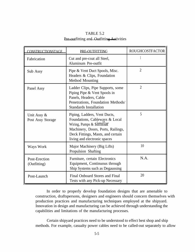
TABLE 5.2Pre-outfitting and Outfitting Activities
CONSTRUCTIONSTAGE PRE-OUTFITTING ROUGHCOSTFACTOR
Fabrication Cut and pre-coat all Steel, 1Aluminum Pre-outfit
Sub Assy Pipe & Vent Duct Spools, Misc. 2Headers & Clips, FoundationMethod Mounting
Panel Assy Ladder Clips, Pipe Supports, some 2Piping Pipe & Vent Spools inPanels, Headers, CablePenetrations, Foundation Methods/Standards Installation
Unit Assy & Piping, Ladders, Vent Ducts, 5Post Assy Storage Foundations, Cableways & Local
Wiring, Pumps & similarMachinery, Doors, Ports, Railings,Deck Fittings, Masts, and certainliving and electronic spaces
Ways Work Major Machinery (Big Lifts) 10Propulsion Shafting
Post-Erection Furniture, certain Electronics N.A.
(Outfitting) Equipment, Continuous throughShip Systems such as Degaussing
Post-Launch Final Onboard Stores and Final 20Tests with any Pick-up Necessary
In order to properly develop foundation designs that are amenable toconstruction, draftspersons, designers and engineers should concern themselves withproduction practices and manufacturing techniques employed at the shipyard.Innovation in design and manufacturing can be achieved through understanding thecapabilities and limitations of the manufacturing processes.
Certain shipyard practices need to be understood to effect best shop and shipmethods. For example, casualty power cables need to be called-out separately to allow
5-5
them to be made up as a separate job in the electric shop. On board ship, the design ofpiping runs and piping hangers should take into account the amount of pre-outfittingdone in the unit assembly. Other techniques need to be understood as critical in amodem yard:
●
●
●
●
●
●
●
●
●
●
●
●
Welding, both structural and for attachmentsStraighteningHydro and air testing of tanks and compartmentsSurface preparation (e.g., sandblasting)Painting and coatingSheathing or insulating - sequence for installationInstallation of ducting, piping, cable, design of hangersInstallation of machinery and electrical equipmentProtection of equipment during erectionTesting of erection jointsTesting of Systems (e.g., ventilation flows)Preparation and preservation of erection joints
While all these techniques are not necessary to the development of foundationdesigns, the awareness of these techniques will facilitate the installation of equipmentand system components. All equipments and system components are outfit items thatneed to be securely mounted to the ship and as such can in a general way criteria forfoundation design can apply to both equipment and system installations.
6.0 PRODUCIBILITY PRINCIPLES FOR SHIP CONSTRUCTION
The producibility design objective is to quantify the design performance requirementsand to satisfy the requirements with an economical design solution. In order to achieve thesegoals consistent with other ship design requirements the following objectives are cited
● Ensure that ships as designed can be built with speed and economy
● Ensure that excessive sophistication
● Ensure that producibility is givenbuilding program
is not built in
due consideration throughout the ship
● Ensure that the staff are familiar with the ship producibility design intent.
Implementation of designs which reflect the most cost effective constructionmethodology will collectively achieve substantial cost savings during follow ship construction.Through achievement of an understanding of how construction of lead and follow ships willbe affected, the designer is guided to select approaches reflecting optimum constructionmethods.
p Construction: Shipbuilding is changing. New ship construction is no longera matter of bringing materials to the ways for erection. No longer can a shipyard remaincompetitive by completely outfitting a hull floating in water. No longer can the skills of ashipwright be depended upon to have been handed down from father to son through longapprenticeship. However, even with the advent of modern techniques for modular hullconstruction, vestiges of shipwright practices influence the construction of ships. Designpractices developed to suit traditional outfitting survive in the outfitting practices utilized inmodular construction. Labor intensive practices indulged by necessity when ships wereconstructed on the ways, must be changed to be compatible with modular constructiontechniques. Design solutions to reduce the high cost of outfitting are achievable throughapplication of engineering first principles and testing to validate lower cost designs.
The shipyard has evolved to becoming more of amanufacturing activity and an assembly plant combined. As reducing costs to become worldcompetitive becomes more imperative, shipyards will have to evolve their assembly processesto become more effective.
6-1
Work in shipyards has been simplified by breaking it down to fit into prescribed stagesof construction. These stages are separated into different divisions at different yards. Theobjective is the same however, to simplify the workers job and to eliminate unnecessarymovement of materials. Typical stages of construction are:
● Fabrication● Subassembly● Panel Assembly● Unit Assembly● Erection• Launching● Final Overboard
Preoutfitting is done prior to erection, outfitting is done after erection. Erection consistsof putting large assemblies (units) into their final position as part of the ship.
Material Flow: In parallel with the construction stages, are the stages of material flow. Thematerials are received, sorted, stored, processed, kitted or subassembled, and installed.Material flow has evolved significantly from that used when building ships on the ways. Intraditional ship construction materials were transported piece by piece to the construction siteaboard ship. Modern subassembly practice with pre-outfitting has reduced the amount ofmaterial handling and ship fitting. However such work is still accomplished in mannersreminiscent of traditional ship building practice. Material flow techniques need to evolve tosupport assembly line manufacturing in order to outperform our world class competitors.
Producibility principles must start with the idea of improving our ships and ourshipyards.
● Upgrade our shipyards by setting up combinations of places for men, materialsand machines that will produce improved ships for less expenditures of man-hours and dollars.
● Keep ships simple, but refined enough to accomplish their basic mission.
● Design ships to fit the production processes, as well as their ultimate use.
Producibility in principle, starts with the idea that production techniques that arise fromsound production planning principles must be reflected in design to be used effectively.
6-2
Certain fundamental principles, or first principles of production lead to productiontechniques that must be considered by the designer in order to achieve optimum results.Producibility for foundations no less than other disciplines, involves the application ofproduction planning principles; especially:
ACCESS TRADE SEQUENCEONE-TIME SKILL APPLICATIONINSIDE WORKDOWN HAND WORKSHOP PACKAGES
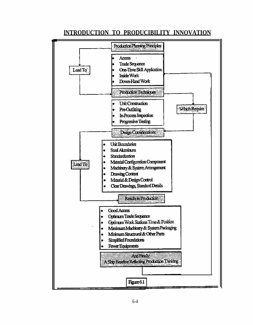
Such principles lead logically to production techniques, design considerations andultimately to the desired improved results in production that will lead shipyards to world classproductivity. See Figure 6.1. For example, all the above principles are served by the techniquesof unit construction and pre-outfitting; however, unit boundaries must be observed andmaintained by designers, both in structure, foundations for equipment and in through-shipsystems design. These principles were outlined in the Producibility Assurance Manualdeveloped for the Patrol Frigate Program.
6-3
lNTRODUCTION TO PRODUCIBILITY INNOVATION
6-4
6.1 Production Principles
Figure 6.1 illustrates how production planning principles relate to productiontechnologies which require design considerations that lead to positive results inproduction. Since these principles are essential to efficient and cost effectivefoundation development they are discussed in some detail in this section and sections6.2,6.3 and 6.4.
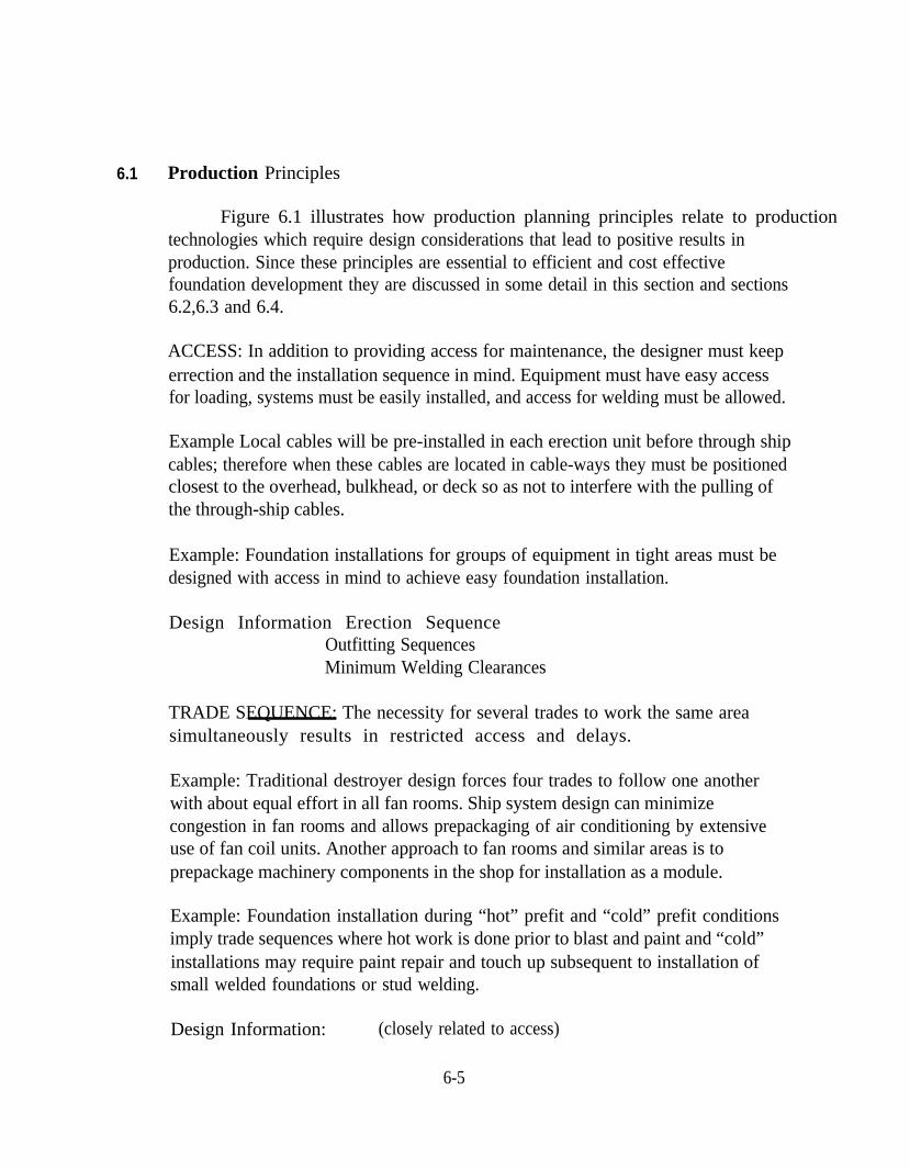
ACCESS: In addition to providing access for maintenance, the designer must keeperrection and the installation sequence in mind. Equipment must have easy accessfor loading, systems must be easily installed, and access for welding must be allowed.
Example Local cables will be pre-installed in each erection unit before through shipcables; therefore when these cables are located in cable-ways they must be positionedclosest to the overhead, bulkhead, or deck so as not to interfere with the pulling ofthe through-ship cables.
Example: Foundation installations for groups of equipment in tight areas must bedesigned with access in mind to achieve easy foundation installation.
Design Information Erection Sequence Outfitting SequencesMinimum Welding Clearances
TRADE SEQUENCE: The necessity for several trades to work the same areasimultaneously results in restricted access and delays.
Example: Traditional destroyer design forces four trades to follow one anotherwith about equal effort in all fan rooms. Ship system design can minimizecongestion in fan rooms and allows prepackaging of air conditioning by extensiveuse of fan coil units. Another approach to fan rooms and similar areas is toprepackage machinery components in the shop for installation as a module.
Example: Foundation installation during “hot” prefit and “cold” prefit conditionsimply trade sequences where hot work is done prior to blast and paint and “cold”installations may require paint repair and touch up subsequent to installation ofsmall welded foundations or stud welding.
Design Information: (closely related to access)
6-5
ONE-TIME SKILL APPLICATION: It is inherently more efficient to do a singlefunction one time rather than several times. Therefore the designer should provideways to combine operations.
Example: Burning holes for pipe, duct, and cable all at once by means of holedrawings and lists is efficient; burning such holes by trade “as required” is not.
Example: Foundations installed by the use of standard method mounting or by useof studs can be accomplished all at once.
Design Information: Erection SequenceMaterial FlowFacilities Available
INSIDE WORK: Work done out of the weather is more efficient than work donesubject to rain, ice, and wide temperature fluctuations. This fact is one of thefundamental reasons for preoutfitting as early in the stages of construction aspossible. The typical stages of construction are fabrication, subassembly and panelwork, unit assembly (in the largest assembly building), unit storage (where furtherwork is done), erection on the ways, and post launching or outfitting work. Workdone prior to erection, other than basic structure, is called preoutfitting. Shop-builtitems are called shop manufacture, e.g., pipe assemblies.
Example: Foundation fabrication in a shop under controlled conditions andinstalled according to plan during a preoutfitting sequence during sub-assembly, unitassembly is much preferred to those assembled or fitted aboard ship at a later stageof construction.
Example: Blasting and priming steel plates in a controlled environment blastfacility is some 27 times cheaper than the same job done later on the ways.
Design Information: Example Affecting DesignStructural and Preoutfitting Procedures
DOWNHAND WORK: One of the corollary principles to access and location isthe inherent efficiency of working downhand vice working overhead. The idea is byno means new; it has been measured with precision for downhand welding. The ideabecome more subtle when all operations are considered. The designer shouldfacilitate planned downhand work by design.
6-6
Example: Pipe and cable hangers and some vent trunks will be installed on thedecks inverted. Dimensions from the deck “below” cannot be used, unless there is aphysically available reference point. Therefore, all dimensions must be fromstructure physically present at the time of construction.
Example: Foundations for equipment with upper supports can be installed in thedown hand position with the upper support installed with the deck in the invertedposition. With clever design fit-up to the equipment can be easily accomplished.
Design Information: Structural and Preoutfitting Procedures.
SHOP PACKAGES: Another corollary of the location principle is the need to getmachinery assembled in parallel with overall ship construction. Access and sequenceof work are improved by grouping equipment for installation together in a shortperiod of time on board.
Normally installation of small auxiliary systems must be delayed at least tothe unit assembly stage, and frequently to post-erection. By this time they are“critical path” items, demanding installation, hook-up and testing in a relativelyshort time. By assembling the components on a common subbase (packaging),assembly, hook-up and testing may proceed in parallel with steel work. The systemwhen installed is ready to go. In addition to the savings resulting from doing thework early in the shop, security against schedule slippage is obtained. Such slippagewould be made up using expensive premium time.
For warship design, systems are typically configured for packaging wherevertechnically feasible. Due to schedule constraints, actual pre-packaging may not bepracticable on the lead ship. The configuration, however, will give a follow shipyardthe option of packaging to the extent they desire.
Example: Pumps, valves, receivers, and piping can be grouped together on acommon foundation. The clever use of the principle by the designer can greatly aidmachinery installation.
In the structural area, shop packages imply the minimum number of parts,and a maximum number of identical parts.
Example: Brackets whose angle varies only slightly for several applications can bedesigned to allow fabrication of standard brackets and shop assemblies with latertrimming.
6-7
6.2
Furthermore, a series of shop manufactured like items are often cheaper thanpurchasing. Standard designs for method mounting facilitate the design andinstallation of foundations.
Example: A series of many similar sheet metal jobs can be set up very efficiently.
Design Information: Structural and Preoutfitting ProceduresWork scopes for shops
STANDARDS: Standards reduce the design, engineering and production costs forfoundations. Proper standards are developed to take into account productionplanning principles. Standards should address fabrication of the foundation andinstallation aboard ship to facilitate the most cost effective installation.
Example: Standard Foundation Method Mounting for power panels eliminates theneed for engineering repetitive designs unless, of course, the standard can be revisedto reduce costs of construction or installation. Standards facilitate planning, designdevelopment, preoutfitting and overall cost reduction.
Production Techniques
The selection of erection units as based on how to best accommodate variousproduction requirements. Subassemblies and assemblies are utilized to provideflexibility in construction.
The boundaries for subassemblies, assemblies and units are determined basedon compromise between conflicting considerations of weight, length, accessibilityand erection sequence. Unit and sub-unit boundaries must reflect for each shipyard,the location and capabilities of certain shipyard operations, which affect the design.There must be access and provision for connecting systems that extend betweensubassemblies, assemblies and units.
Considerations that affect the selection of boundaries include the following
● Each unit is a block of the ship’s structure and installed pre-outfit material.Its weight should beat or near the maximum lifting capacity of the yard.Heavy lifts result in fewer units per ship which in turn allows a shorter totalelapsed time for ship erection and a greater opportunity for pre-outfitting costsavings. Each shipyard’s lift capacity in assembly and erection varies. It isrecognized that not all follow yards will have lift capacity as the lead yard in a
6-8
●
●
●
●
agile enterprise. Such yards may transport the units without lifting or maymake a further breakdown into sub-units. Virtual shipyards, using agilecollaborative enterprise as a basis for cooperation can develop specificdesigns unique for each shipyard using Simulation Based Design (SBD) and a ship product model. In this fashion the ship product model can be tailored tosuit the specific shipyard manufacturing requirements. Subassembly,assembly and unit size can be planned and executed for each agilecollaborative member. Shipyard planning will be facilitated using such amodel.
The unit length (in the hull) is governed by yard planning considerations andshipyard equipment capability. The maximum usable length of the platerolling equipment and at follow yards influences unit size.
“Natural” breaks in the ship’s structure help to form a selection of unitboundaries. Breaks are arranged so that each succeeding unit is set in placeby moving it toward existing structure and down, to minimize handling andfitting.
A single deck unit usually includes the deck structure and the bulkheads andshell below. Multi-level units consist of single deck units stacked one aboveanother. These units are generally constructed and pre-outfitted in aninverted position, then turned upright for final preoutfit and final painting.Decks are usually arranged to be continuous through bulkheads.
Shell seams are usually arranged to be slightly above deck levels (6 to 12 in.),and shell butts such that they occur slightly (12 to 24 in.) forward or aft oftransverse bulkheads, depending on the location of the bulkheads.
Compartments which are to be heavily pre-outfitted are completely enclosedwithin the unit boundaries. The best examples are the auxiliary machineryrooms. Other examples include living and some electronic spaces.
The maintenance of unit boundaries is an important design function. Here are somegeneralities:
● To the extent controllable by the stage of design, transverse bulkheads shouldbe kept in the same plane from level to level. The bulkhead line-up occursalmost naturally in the hull structure due to the compartmentalization.However, it requires careful consideration in the deckhouse. This
6-9
requirement should also be applied topossible. Such a design approach will
longitudinal bulkheads whereverproduce very clean unit boundaries.
● Foundations for equipment should be located on a single surface, such as adeck, bulkhead or shell. An effort should be made to locate foundations toline-up with existing structure to eliminate headers. When possible headerson the same side as the foundation are preferred. Furthermore, extensive useof common foundations avoid the use of small headers. (This will notnecessarily apply to main turbines, reduction gears, and major auxiliaries.)Where possible, machinery and other equipment to be installed on a deckshould be located far enough inboard so that the next deck unit can belowered into place without disrupting the installed equipment below it.
● Butts in longitudinal and transverse frames should occur at or as close to shellbreaks as possible. In areas with shape the butt must occur on the“narrowing” side to facilitate erection.
● Systems must be designed with minimum crossing of erection breaks, andwhere crossing is necessary, with suitable make-up provisions in way ofbreaks.
Build strategies using modular construction methods typically organize modules intothe following:
● Aft body and machinery spaces● Mid-body sections● Fore body● Superstructure.
Modular construction is facilitated by organizing the design to produce modules thatcan be efficiently installed in the hull modules. They are
●
●
●
●
●
●
●
●
Machinery equipment modulesMain engine modulesPropulsion system modulesCargo system modulesThruster modulesDeck system modulesUptake modulesBridge system modules.
6-10
6.3 Design Considerations
Figure 6.1 illustrates how Production Planning Principles effect producibilityand Production Techniques which will naturally lead to design considerations thatmust be undertaken if cost saving production results are to be achieved. The buildstrategy employed results in a set of design and engineering requirements necessaryto achieve productivity goals and assurance of achieving performance requirements.
tional Approach to Design: The consortium approach to theshipbuilding design and shipbuilding process is to use Simulation Based Design(SBD) to facilitate shipyard build processes. Agile manufacturing techniques requiredesigns to be developed that can be built in different facilities with varying buildstrategies. Or conversely, hull units can be built in different facilities and joinedtogether. There is a danger in the use of SBD for ships where construction detailsemulated are based on construction techniques that are traditional and laborintensive. There has been a tendency in warship design to enshrine obsolete designand construction methods. Simulation Based Design affords the opportunity toemploy labor saving standards for foundations, equipment, outfit and systemsinstallations. SBD employed in this manner will amplify ship design andconstruction cost and time savings.
d Scope to Facilitate Build Strategy: . Design and engineering
requirements that will facilitate a competitive build strategy include
● Production information requirements● Procurement information requirements● Modeling and Composites (traditional and/or SBD)● Key Drawings● Design and engineering schedules● Datums and Molded definition● Functional space allocations
The competitive build strategy will be enhanced by the development of appropriatestandards and guidelines:
● Design Standards● Material Standards● Production Standards● Detail Design Guidelines
-- Steel Work -- Machinery
6-11
-- Pipe Work -- Electrical-- Joiner Work -- Paintwork
● Change Order Management
During detail design development,
pre-outfitting and other cost saving techniques can be implemented by carefulattention to erection breaks, installation sequence, producibility design in general.For convenience the following list represents a summary of considerations forproducibility:
1.
2.
3.4.5.6.
7.8.9.
10.11.12.
13.14.15.16.
17.
18.
19.20.21.22.
Work simplification by spreading the operations out during several stages ofconstruction.Materials in process and flowing to the constructions stages requiringMaterial Control techniques.Production planning using units and work scopes.Access during assembly, erection, and installation.Sequencing of trade work.Combine production operations for savings inherent in applying skilled workonce.Inside work for efficiency.Downhand work - a planned sequence.Shop packages for manufacturing groups of items, some on commonfoundations.Unit boundaries for structure and systems; as elaborated further below.Standardization of all types affecting production.Drawing content and format for best use by loft, trades and productionplanners.Design control to avoid interferences.Standard details for clarity, etc. Ease of checking and validation during design and construction.Allowance for changes on drawings resulting from corrections, refinements,and innovations.Allowance for differences in follow ships built by follow yards and partners invirtual shipyards consisting of agile collaborative enterprises.Awareness of the reasoning behind the selection and maintenance of unit andsubunit structural breaks.The critical nature of the machinery zone during construction.Cost factors associated with the stages of construction.Welding.Straightening.
6-12
23.24.25.26.27.28.29.30.
Testing of tanks and compartments.Testing of systems.Surface preparation together with preservation.Sheathing and insulating. Installation of distribution systems.Installation of purchased equipment.Protection of equipment during constructionErection joints: testing, preparation, and preservation.
6.4 Benefits to Production
As indicated in Figure 6.1 production planning principles which lead tocomplimentary production techniques require producibility design considerationsthat will result in benefits to production in terms of good access, optimum tradesequence, optimum work station time and position, maximum machinery andsystems packaging, minimum structure, parts and pieces, simplified foundations andsystems installations and fewer equipments. The total producibility enterpriseembodied in the preceding sections will result in a ship design baseline thatthoroughly reflects production thinking.
Historically, the management of the design and engineering effort evolvedaround the practice of extrapolating designs from past practice to provide assurancethat designs were satisfactory from performance standpoints. The sequence ofdesign development required that draftsmen and designers expend significant effortto develop an integrated design package adequate for engineering review andapproval. This process resulted in little chance to integrate producibility orproduction considerations into the development of foundation designs.
A turnabout in concern for competitiveness and cost required thatproducibility and production considerations be given equal billing with performanceissues. By reordering the priorities and the sequence of the design and engineeringeffort, producibility and production considerations have been incorporated into thedevelopment of foundation designs early in the design sequence so that significantproduction cost savings can be achieved while engineering into the design adequatefoundation system performance capability. The development of standards also willreduce design and engineering costs.
6-13
7.0 PRODUCIBILITY AND INNOVATION FOR FOUNDATIONS
This sections elaborates in detail the producibility features and cost-saving productiontechniques for foundations and installations. Some very innovative producibility concepts incompliance with principles and techniques of ship production are also highlighted. Weight andcost reduction through standardization of foundation design, fabrication and installation arealso discussed.
7.1 Producibility Principles for Foundations
The following guide-lines reflect the concept that “producibility assurance is away to lower follow ship production costs by communicating shipyard productionconsiderations to the designer. “Through achievement of an understanding of howshipyard construction of lead and follow ships will be affected, the designer is guidedto select approaches reflecting shipyard optimum construction methods.Implementation of designs which reflect the most cost effective constructionmethodology will collectively achieve substantial cost savings during follow shipconstruction. This approach when consistently applied should result in thedevelopment, when appropriate, of the standardization of scantlings for variousfoundation configurations consistent with equipment weight and geometry.
The elements of effective principles of producibility design for foundations are identifiedin the following guide-lines. They are:
1. The Producibility of Foundations should be based on achieving the mostproducible structural designs while meeting the requirements of thespecifications. For any one foundation there should be a best solution in termsof structural fabrication producibility. However, the science or art ofshipbuilding is a multi-disciplinary effort, where each discipline tries to achieveproducibility engineered designs. As a result designs developed to suitproducibility considerations in one discipline may preclude development ofequally producible designs within other disciplines.
Since foundation design normally takes place after the functional arrangementof the equipment has been integrated into the ship design with supporting shipssystems, there may be only limited geometrical flexibility remaining to achieveproducible foundation designs. However, some accommodation by systems orequipment arrangements may be possible and should be pursued in order toachieve optimum producible foundations.
7-1
2.
3.
4.
5.
6.
Foundations should be initially designed by the hull draftperson to provideminimum support for equipment. The brackets, bracing & scantlings shouldbe checked by the hull designer and reconfigured if necessary by bothdesigner and draftsmen.
Develop designs which require a minimum number of operations per piece.
Make foundations rectilinear in configuration.
Foundation headers on opposite sides of bulkhead or deck should be avoidedwhere possible. Production scheduling usually causes headers to be addedafter the basic structure is finished.
Provide sufficient access to facilitate installation and welding.
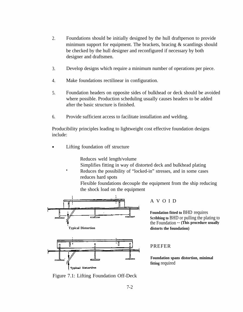
Producibility principles leading to lightweight cost effective foundation designsinclude:
● Lifting foundation off structure
Reduces weld length/volumeSimplifies fitting in way of distorted deck and bulkhead plating
• Reduces the possibility of “locked-in” stresses, and in some casesreduces hard spotsFlexible foundations decouple the equipment from the ship reducingthe shock load on the equipment
Typical Distortion
A V O I D
Foundation fitted to BHD requiresScribbing to BHD or pulling the plating tothe Foundation -- (This procedure usuallydistorts the foundation)
PREFER
Foundation spans distortion, minimalfitting required
Figure 7.1: Lifting Foundation Off-Deck
7-2
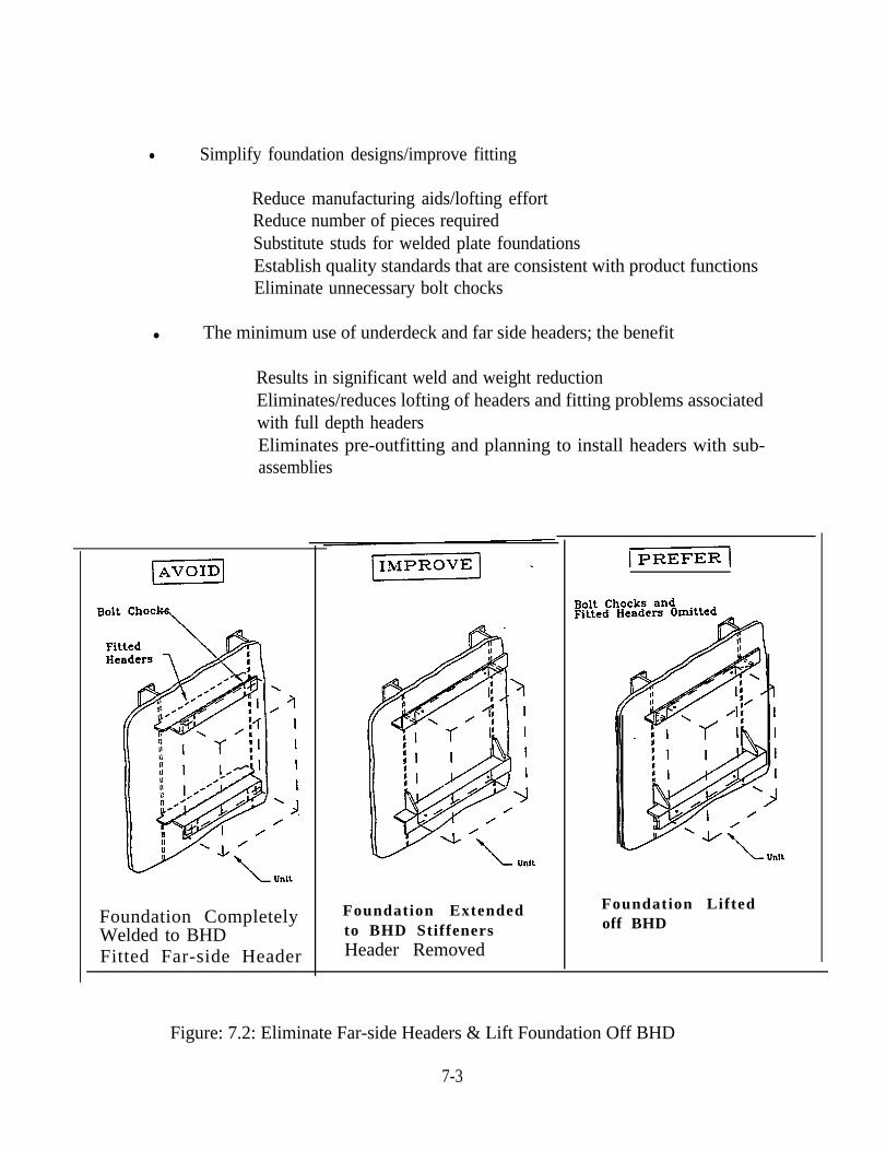
● Simplify foundation designs/improve fitting
Reduce manufacturing aids/lofting effortReduce number of pieces requiredSubstitute studs for welded plate foundationsEstablish quality standards that are consistent with product functionsEliminate unnecessary bolt chocks
● The minimum use of underdeck and far side headers; the benefit
Results in significant weld and weight reductionEliminates/reduces lofting of headers and fitting problems associatedwith full depth headersEliminates pre-outfitting and planning to install headers with sub-assemblies
Foundation CompletelyWelded to BHDFitted Far-side Header
Foundation Extendedto BHD StiffenersHeader Removed
Foundation Liftedoff BHD
Figure: 7.2: Eliminate Far-side Headers & Lift Foundation Off BHD
7-3
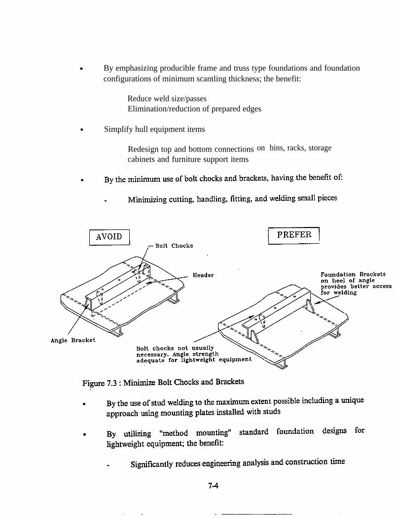
● By emphasizing producible frame and truss type foundations and foundationconfigurations of minimum scantling thickness; the benefit:
Reduce weld size/passesElimination/reduction of prepared edges
● Simplify hull equipment items
Redesign top and bottom connectionscabinets and furniture support items
on bins, racks, storage
7.2 Innovative Producibility Concepts
Producibility design concepts are inherently a part of structural optimization andare especially necessary to stay within the cost constraints of the final price of thespecific ship or series of ships. While the majority of technical specifications strive toachieve the best technical solution for a given issue, the producibility design objectiveis to quantify the design performance requirements and to satisfy the requirement withan economical design solution.
The design of foundations specially for naval ships has become very complex.Vibration, stiffness, and shock criteria are but a few of the factors involved. In the pastlittle analysis of fabrication methods had been conducted. Recently conducted studiesprovide quantitative guidance to the designer. Results of these studies indicate thatcombined shape and flanged plate construction result in least cost construction.
Steel foundations were categorized as to the type and then divided into twogroups depending on the weight of components they support, for study. Theconclusions are as follows:
1.
2.
3.
4.
5.
6.
7.
8.
In general shapes, especially angle bar, produce the least expensiveconstruction
In somecases combining flanged plates and shapes may be less expensive.
In high weight equipment foundations weldments are approx. 60% moreexpensive than shapes.
In case of light weightexpensive than shapes
foundations weldments are approx. 43% more
Weldments and flanged plate construction tend to be 7% to 10% heavierthan shape construction.
Do not use a flanged plate to replace a standard shape.
Consider flanged plates to replace weldments.
Weldments may be used where shapes and/or flanged plates areimpracticable.
7-5
7.3 Foundation Integration with Hull Construction
There is great savings potential through foundation integration with hullconstruction. The methods used to achieve these savings should be intelligently implemented so that the performance and maintenance of the supported equipment isnot compromised with.
● Eliminate back-up structure
Lift foundations off structureDevelop simple attachmentsLand on soft plating
● Employ standards for equipment foundations and systems
Statistics and technology used to develop standard designsreduces/eliminates repetitive engineeringHi-tech manufacturing, flexible automation and robotics reduces laborand time for manufacturing standardsStandards reduce/eliminate labor-overhead for handling small piece-partsStandards designed for installation simplicity reduce labor and time forinstallationStandards reduce sub-assembly erection, pre-outfit labor and overtimefor ship construction
● Accelerate equipment and systems installations. This reduces time and achievessavings in overall time of construction
● Equipment shall not be supported directly on the shell or other structure exposedto gun blast, missile blast, wave impact, or propeller excited vibrations if theresulting distortion or vibration would damage the equipment or limit itsperformance.
● Foundation members that overhang supporting structure and extend onto deckor bulkhead plating shall be modified to prevent puncturing of the plating byend rotation. Means of accomplishing this include landing the foundationmember on a pad to effect a smooth transition and to reduce the stress in theplating in way of the pad below the fatigue limit. Relative motion of the adjacentboundary structure and maximum permissible vibration amplitudes should beused to calculate the induced stresses in the plating at the edge of the pad. Pad
7-6
geometry and thickness should be designed to minimize plating stress.
● Accessibility shall be provided for inspection and maintenance of equipmentfoundation structure and adjacent hull structure.
● Foundations shall be constructed to avoid pockets which can contain liquid.Openings shall be provided at the base of deck mounted equipment.
● Foundations shall be rigid enough to ensure that the requirements for limitingtwist, bend, level and parallelism with the master datum as specified byequipment manufacturers are met.
● The rigidity of foundations and supporting structure shall be sufficient toprevent misalignment which would interfere with operation of the machineryand equipment, and to preclude excessive vibratory motion or rocking on thefoundation.
● Foundations shall be designed to prevent misalignment or excessive strains dueto thermal expansion under all operating conditions. Large units of machinerysuch as turbines, gears, generators, and condensers which must be aligned withconnected equipment shall be installed in proper chocks.
7.4 Foundation Standards and Cost Reduction
Ship costing is an extensive task and involves innumerous iterations. Specificcosting on foundations is hard to obtain because the foundation design, fabrication andinstallation include many processes. Handling, preparation, dead time are difficult todetermine. Costing by measuring weight saved, weld length is too simplistic and willgive erroneous estimation. An aggressive policy on foundation weight reductioncombined with producibility initiatives to reduce the labor involved in fabrication andinstallation must be pursued and should be integral with the overall WeightProgram.
Control
A substantial extent of ship construction cost saving can be achieved by
1. Foundations, equipment, and ship system installations on critical path
2. Savings in time and cost of foundation and system hanger fabrication andinstallation
7-7
3. Savings in time and cost of equipment and system installations
4. Savings in time and cost of construction of sub-assemblies
5. Savings in overall time and cost of ship construction
The following steps highlight the means to achieve weight reduction and shipconstruction cost savings:
● Standardization of foundations to achieve cost savings
Make foundations and ship system hangers more cost effectiveFoundations and ship system hangers are a small percentage of overallsteel weight and outfit - however, relative cost is very highHistorically - a great effort has been made to optimize primary hullstructures. Little attention has been given to reducing the very high costof foundations.Standardization of equipment foundations and system hangers usingstatistics and technology development will lead to significant reductionsin fabrication cost and installation timeStandard design and installation will lead to smaller shipyard schedule
● Time and cost savings design features
Develop standard foundations for a variety of equipmentReduce weldingReduce materialReduced fabrication / fit-upReduce installation timeUnique cost savings installation techniques
Weight savings potential: 45% to 50%Cost savings potential: 50% of weldingReduce number of pieces: 50%
Develop simplified attachment techniques:Reduces time for installation of foundationsPaves the way to install equipment and systems with theirfoundationsReduces sub-assembly construction time on critical path
Reduces overall time for ship construction
7-8
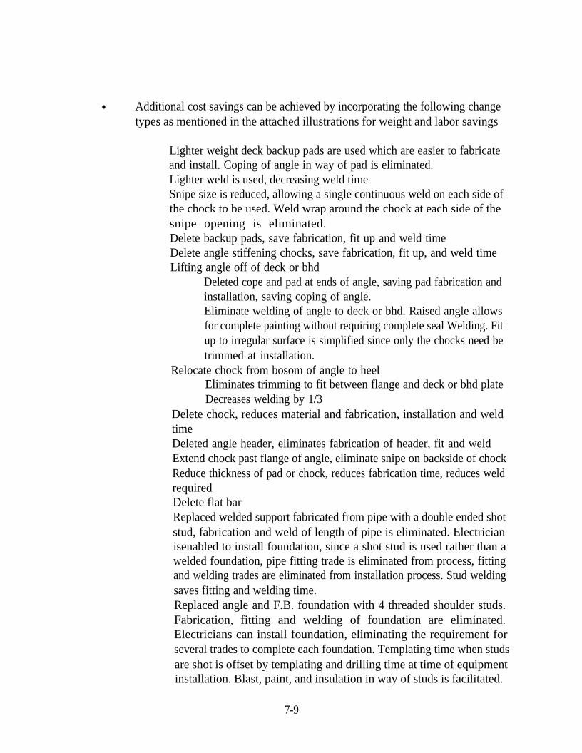
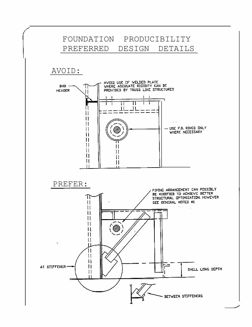
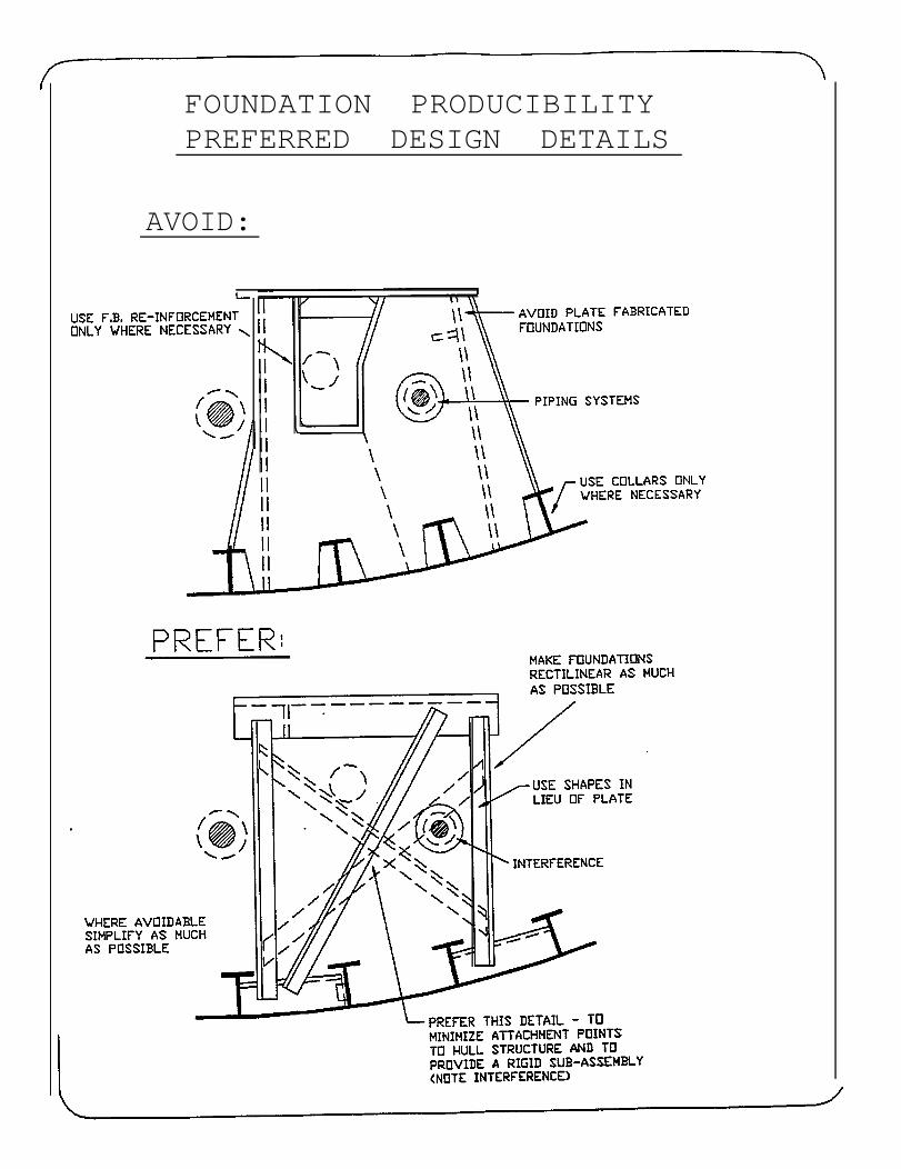
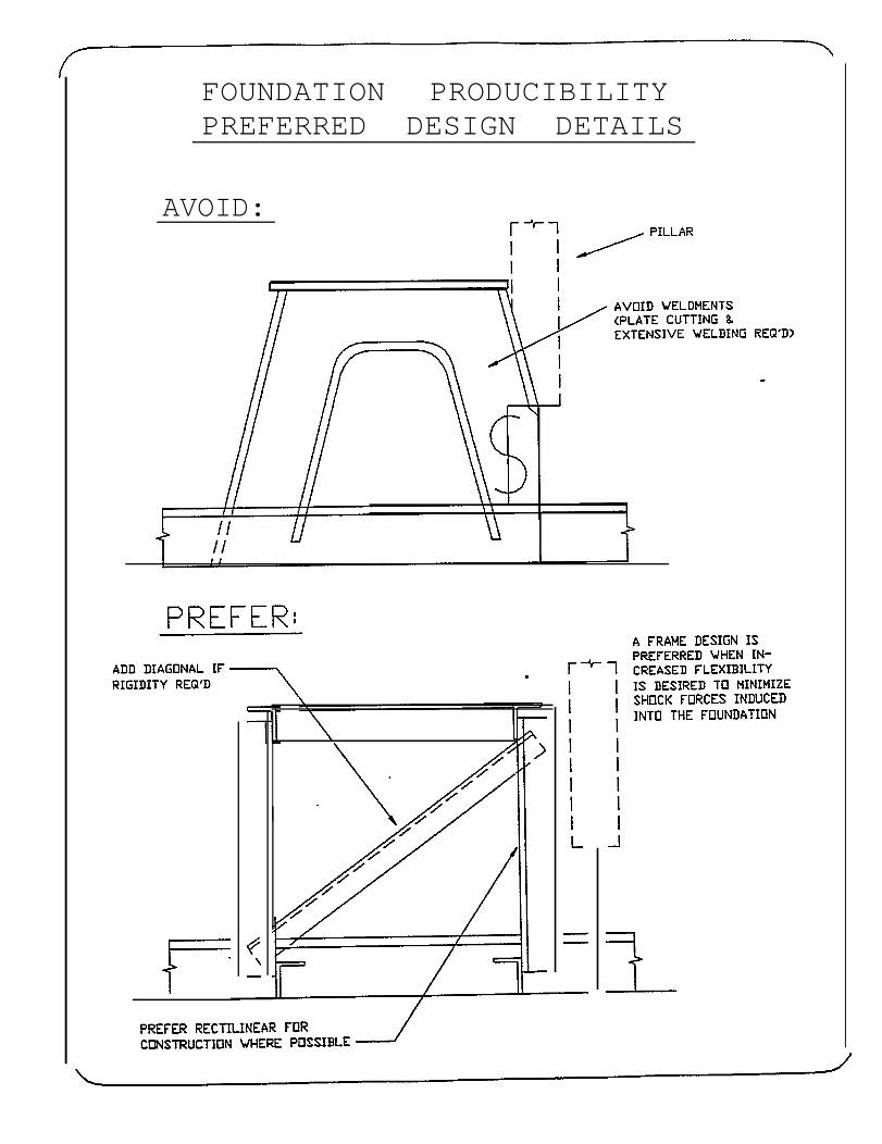
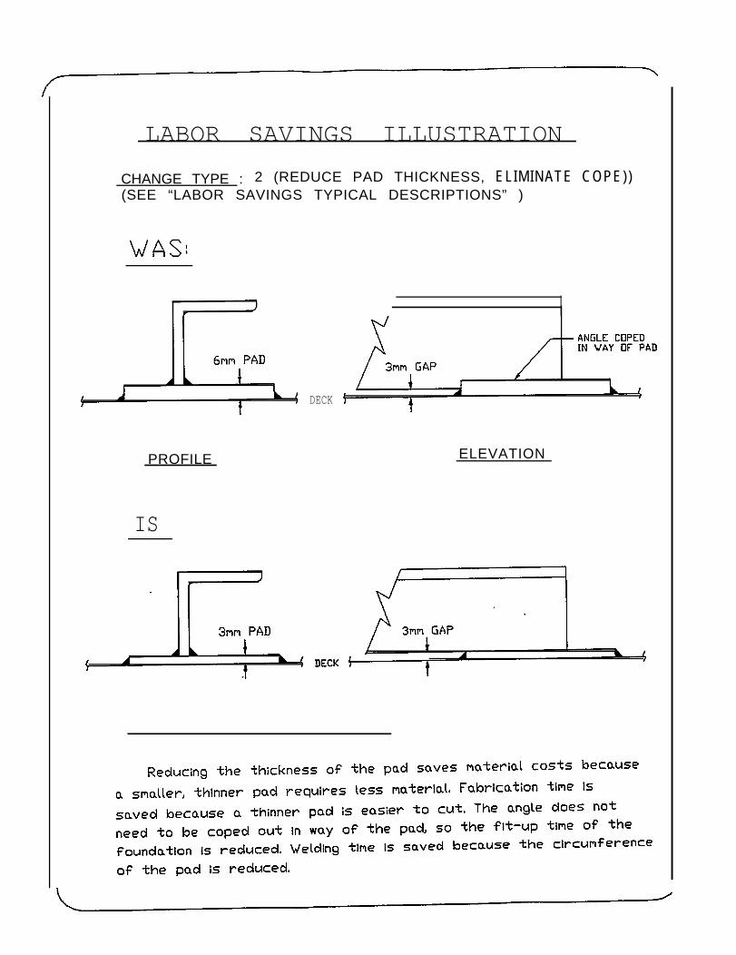
● Additional cost savings can be achieved by incorporating the following changetypes as mentioned in the attached illustrations for weight and labor savings
Lighter weight deck backup pads are used which are easier to fabricateand install. Coping of angle in way of pad is eliminated.Lighter weld is used, decreasing weld timeSnipe size is reduced, allowing a single continuous weld on each side ofthe chock to be used. Weld wrap around the chock at each side of thesnipe opening is eliminated. Delete backup pads, save fabrication, fit up and weld timeDelete angle stiffening chocks, save fabrication, fit up, and weld timeLifting angle off of deck or bhd
Deleted cope and pad at ends of angle, saving pad fabrication andinstallation, saving coping of angle.Eliminate welding of angle to deck or bhd. Raised angle allowsfor complete painting without requiring complete seal Welding. Fitup to irregular surface is simplified since only the chocks need betrimmed at installation.
Relocate chock from bosom of angle to heelEliminates trimming to fit between flange and deck or bhd plateDecreases welding by 1/3
Delete chock, reduces material and fabrication, installation and weldtimeDeleted angle header, eliminates fabrication of header, fit and weldExtend chock past flange of angle, eliminate snipe on backside of chockReduce thickness of pad or chock, reduces fabrication time, reduces weldrequiredDelete flat barReplaced welded support fabricated from pipe with a double ended shotstud, fabrication and weld of length of pipe is eliminated. Electricianisenabled to install foundation, since a shot stud is used rather than awelded foundation, pipe fitting trade is eliminated from process, fittingand welding trades are eliminated from installation process. Stud weldingsaves fitting and welding time.Replaced angle and F.B. foundation with 4 threaded shoulder studs.Fabrication, fitting and welding of foundation are eliminated.Electricians can install foundation, eliminating the requirement forseveral trades to complete each foundation. Templating time when studsare shot is offset by templating and drilling time at time of equipmentinstallation. Blast, paint, and insulation in way of studs is facilitated.
7-9
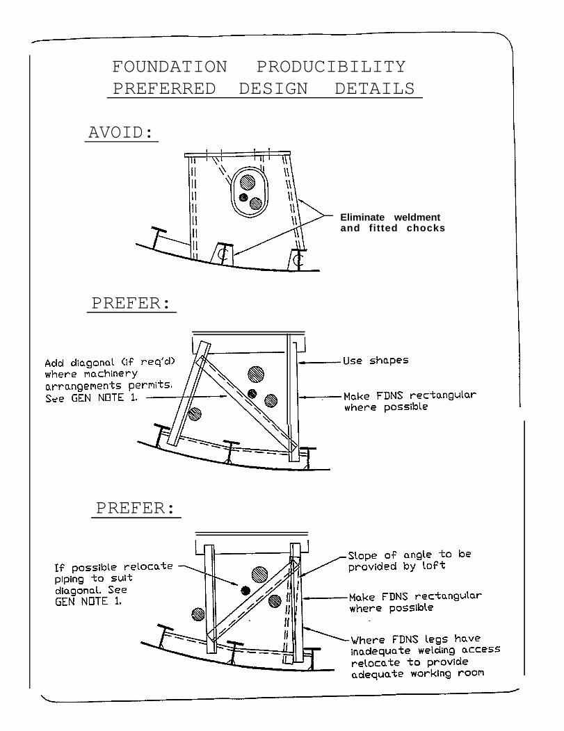
FOUNDATION PRODUCIBILITYPREFERRED DESIGN DETAILS
AVOID:
PREFER:
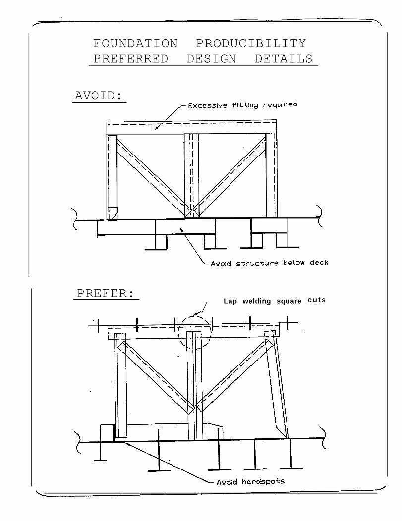
FOUNDATION PRODUCIBILITYPREFERRED DESIGN DETAILS
AVOID:
FOUNDATION PRODUCIBILITYPREFERRED DESIGN DETAILS
AVOID:
FOUNDATION PRODUCIBILITYPREFERRED DESIGN DETAILS
AVOID:
Eliminate weldmentand fitted chocks
PREFER:
PREFER:
FOUNDATION PRODUCIBILITYPREFERRED DESIGN DETAILS
AVOID:
IIIIIII
PREFER:/ Lap welding square
deck
c u t s
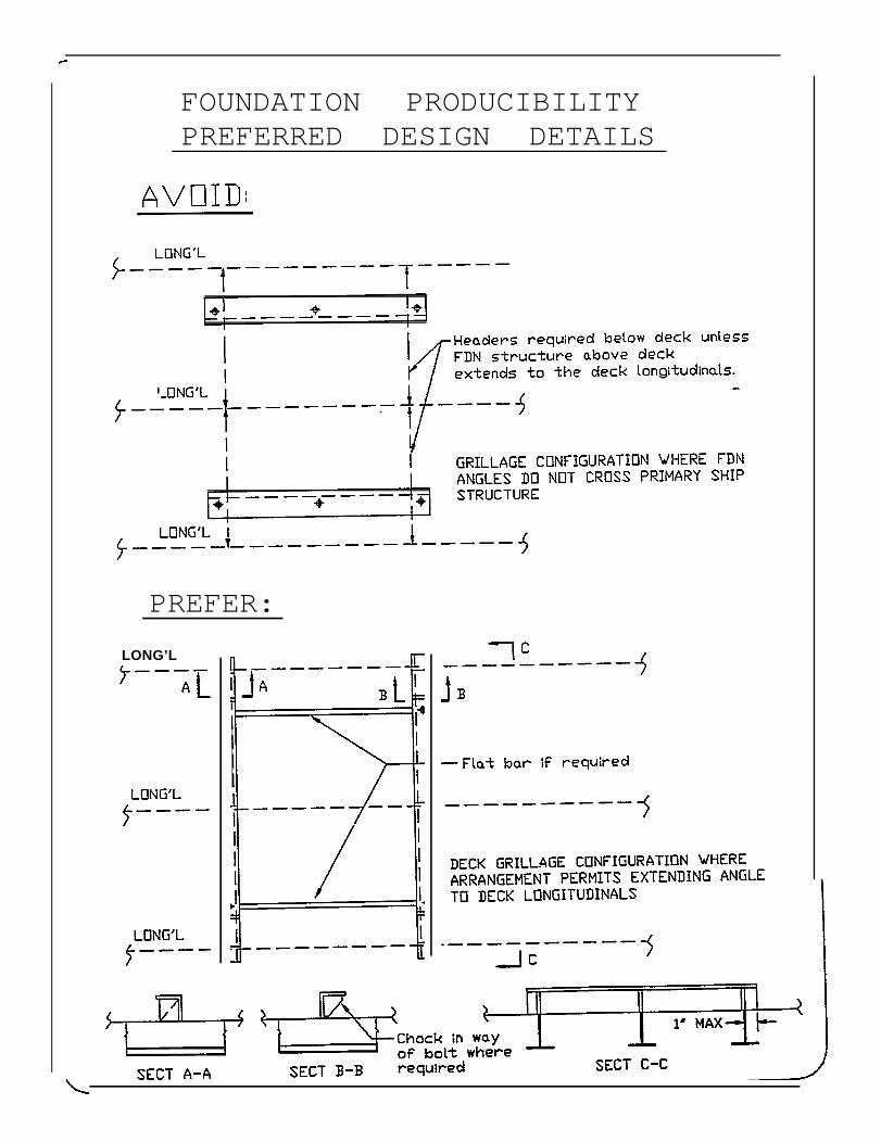
FOUNDATION PRODUCIBILITYPREFERRED DESIGN DETAILS
PREFER:
LONG’L
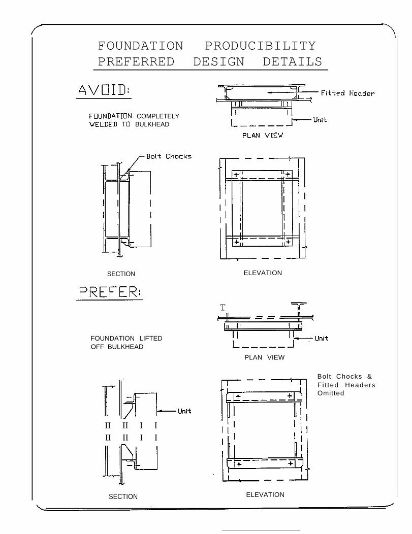
FOUNDATION PRODUCIBILITYPREFERRED DESIGN DETAILS
COMPLETELYBULKHEAD
SECTION
FOUNDATION LIFTEDOFF BULKHEAD
II II I III II I I
ELEVATION
T
PLAN VIEW
SECTION ELEVATION
Bolt Chocks &F i t ted HeadersOmitted
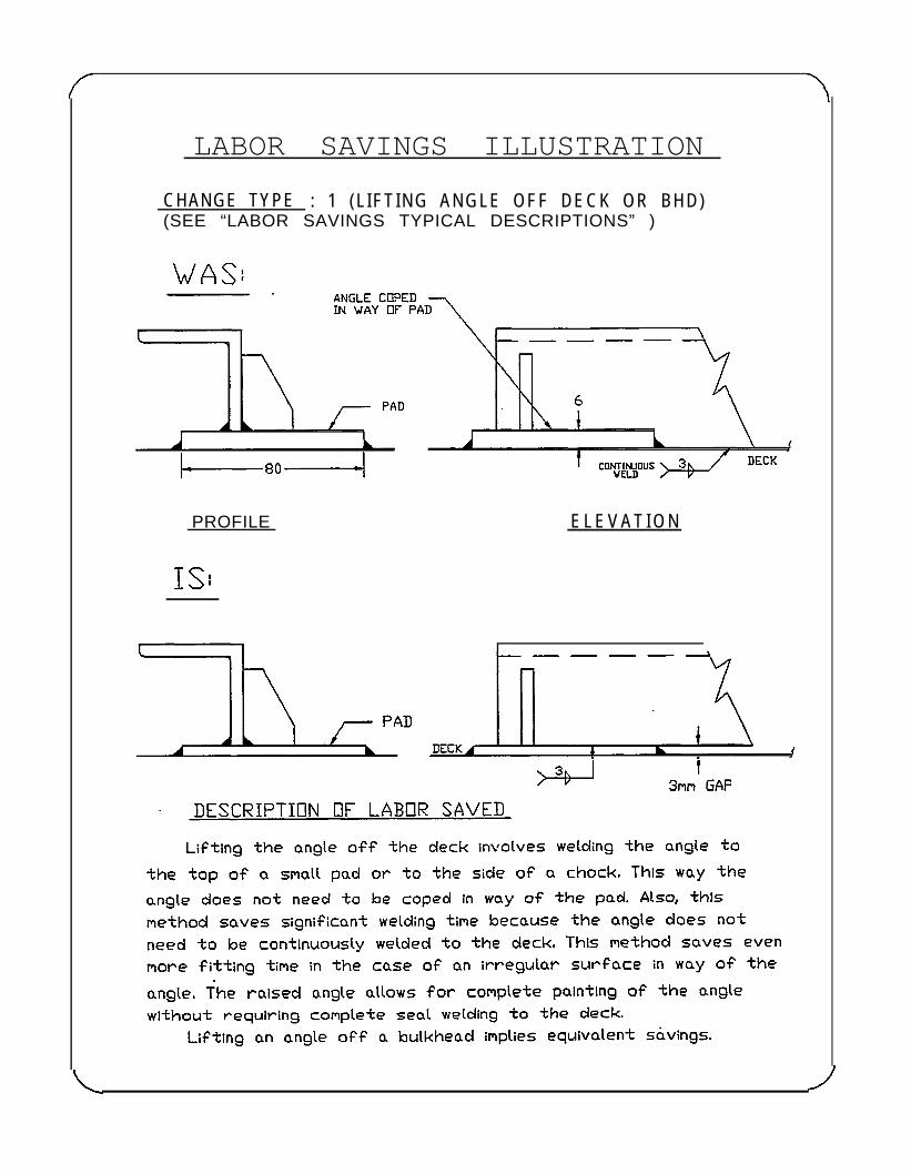
LABOR SAVINGS ILLUSTRATION
CHANGE TYPE : 1 (L IFTING ANGLE OFF DECK OR BHD)(SEE “LABOR SAVINGS TYPICAL DESCRIPTIONS” )
PROFILE E L E V A T I O N
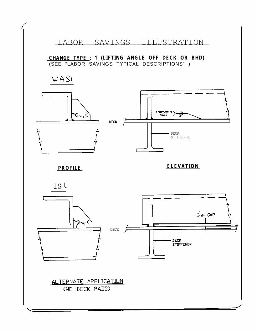
LABOR SAVINGS ILLUSTRATION
CHANGE TYPE : 1 (LIFTING ANGLE OFF DECK OR BHD)(SEE “LABOR SAVINGS TYPICAL DESCRIPTIONS” )
PROFILE
IS t
DECK
/,
DECKSTIFFENER
E L E V A T I O N
LABOR SAVINGS ILLUSTRATION
CHANGE TYPE : 2 (REDUCE PAD THICKNESS, ELIMINATE COPE))(SEE “LABOR SAVINGS TYPICAL DESCRIPTIONS” )
PROFILE
IS
DECK
ELEVATION
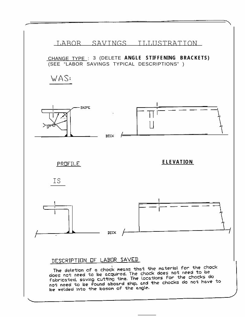
LABOR SAVINGS ILLUSTRATION
CHANGE TYPE : 3 (DELETE ANGLE STIFFENING BRACKETS)(SEE “LABOR SAVINGS TYPICAL DESCRIPTIONS” )
E L E V A T I O N
IS
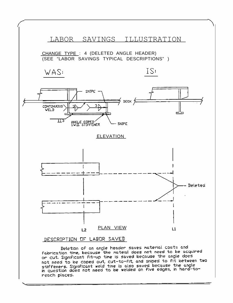
LABOR SAVINGS ILLUSTRATION
CHANGE TYPE : 4 (DELETED ANGLE HEADER)(SEE “LABOR SAVINGS TYPICAL DESCRIPTIONS” )
ELEVATION
L2 PLAN VIEW L1
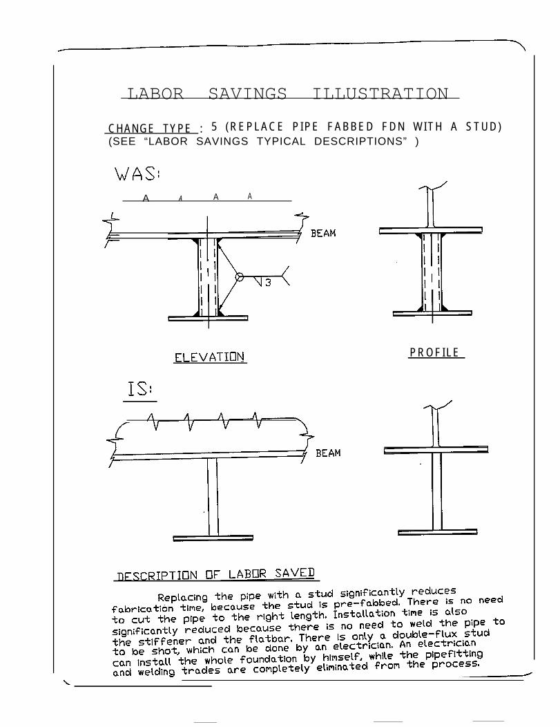
LABOR SAVINGS ILLUSTRATION
CHANGE TYPE : 5 ( R E P L A C E P I P E F A B B E D F D N W I T H A S T U D )(SEE “LABOR SAVINGS TYPICAL DESCRIPTIONS” )
A A A A
PROFILE
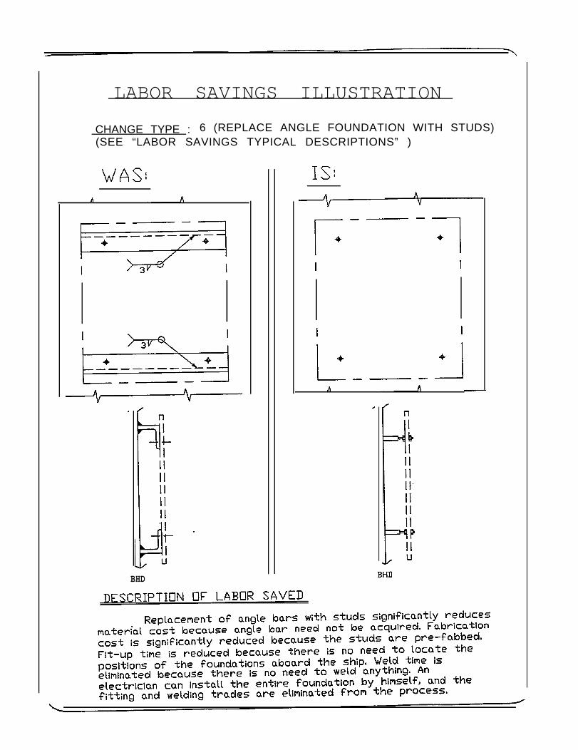
LABOR SAVINGS ILLUSTRATION
CHANGE TYPE : 6 (REPLACE ANGLE FOUNDATION WITH STUDS)(SEE “LABOR SAVINGS TYPICAL DESCRIPTIONS” )
BHD
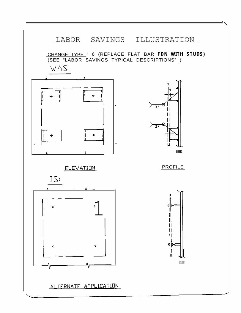
LABOR SAVINGS ILLUSTRATION
CHANGE TYPE : 6 (REPLACE FLAT BAR FDN WITH STUDS)(SEE “LABOR SAVINGS TYPICAL DESCRIPTIONS” )
A A
10
BHD
PROFILE
BHD
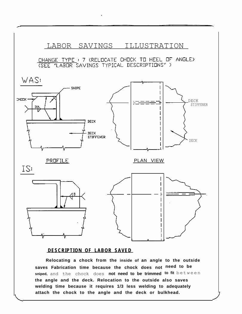
LABOR SAVINGS ILLUSTRATION
PLAN VIEW
DESCRIPTION OF LABOR SAVED
DECKSTIFFENER
DECK
need to beto fit between
Relocating a chock from the inside of an angle to the outside
saves Fabrication time because the chock does notsniped, and the chock does not need to be trimmed
the angle and the deck. Relocation to the outside also saveswelding time because it requires 1/3 less welding to adequatelyattach the chock to the angle and the deck or bulkhead.
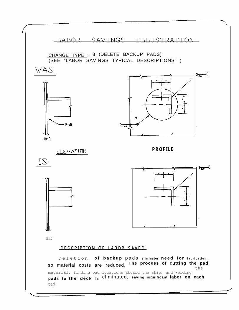
LABOR SAVINGS ILLUSTRATION
CHANGE TYPE : 8 (DELETE BACKUP PADS)(SEE “LABOR SAVINGS TYPICAL DESCRIPTIONS” )
PROFILE
BHD
DESCRIPT ION OF LABOR SAVED
D e l e t i o n o f b a c k u p p a d s e l i m i n a t e s n e e d f o r f a b r i c a t i o n ,
so material costs are reduced, The process of cutting the padthe
material, finding pad locations aboard the ship, and welding
pads to the deck i s eliminated, saving significant labor on each
pad.
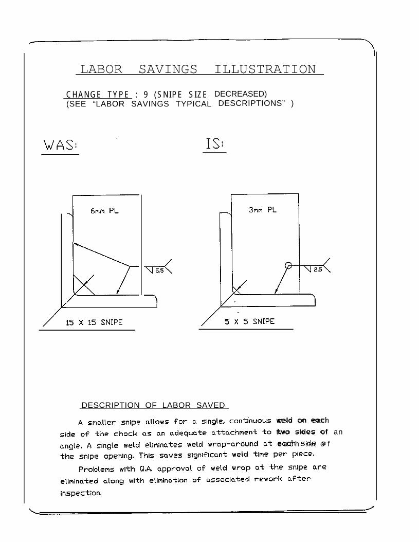
LABOR SAVINGS ILLUSTRATION
CHANGE TYPE : 9 (SNIPE SIZE(SEE “LABOR SAVINGS TYPICAL
I
DECREASED)DESCRIPTIONS” )
DESCRIPTION OF LABOR SAVED
weld on each
two sides of an
e a c h s i d e o f
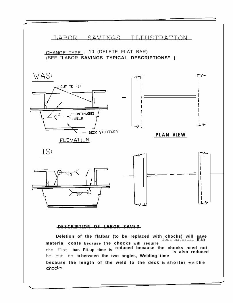
LABOR SAVINGS ILLUSTRATION
CHANGE TYPE : 10 (DELETE FLAT BAR)(SEE “LABOR SAVINGS TYPICAL DESCRIPTIONS” )
P L A N V I E W
DESCRIPTION OF LABOR SAVED
Deletion of the flatbar (to be replaced with chocks) will save
mater ia l costs b e c a u s e the chocks W il l requireless material than
the flat bar. Fit-up time is reduced because the chocks need not
be cut to fit between the two angles, Welding timeis also reduced
because the length of the weld to the deck is s h o r t e r with t h e
8.0 TECHNICAL APPROACH
A conservative approach would be to allow the foundation to be loaded up to50% of the material yield strength due to the worst ship motions. Since ship motionstypically produce 2-3 times the static load, a foundation designed to this criteria wouldbe able to support at least 4-6 times the static load. In design data sheets the seawayloading or the equivalent acceleration values of 3 g’s vertical, 1.5 g’s transverse and 0.75g’s longitudinal are used,simultaneously.
8-1
Any unsatisfactory condition resulting from the excitation of a resonantfrequency in any equipment by the propeller or other exciting force shall be correctedby local stiffening of structure, by installation of suitable mountings, by modificationof components, or other effective means. Means of preventing excessive vibrationduring normal ship operating conditions should be anticipated and incorporated in thedesign and construction of the ship. The correction of a resonance problem in a finishedship can be a very costly and time consuming effort.
8-2
frequencies may reaccommodated. However, since the propeller blade rate will passthrough these frequencies as power is increased or decreased, there exists the possibilitythat a transitory resonant condition may exist.
The action of a ship travelling through a seaway will tend to produce harmonicmotion of a ship’s hull. These motions can be approximated by considering the ship’shull girder as a free-free beam with added mass included to represent the damping effectof the seawater. The resulting natural frequencies and mode shapes are referred to asship’s primary hull modes. It is these hull driving frequencies which should be avoidedin the design of foundations located within the forward part of the ship. Blade rate isusually much higher than any of the primary hull modes and as a result is critical in theaft end of the ship. However, as mentioned above, due to structural damping the bladerate criterion is not critical in the forward length of a ship and as a result the hull modecriterion takes precedence. In designing foundation structures, to avoid resonances withship’s primary hull modes, it is imperative that the mode shape of the driving frequencybe considered. The direction of the driving forces for each hull mode will determinewhich of the foundations natural frequencies should be considered in the criterion. Forexample, the ship’s torsional or rolling mode will have tendency to excite the transversebending mode of a cantilevered foundation structure mounted to the deck.
The case of a foundation supporting a piece of machinery with rotating parts,which occurs often on board ship, requires an additional vibration criterion. For thissituation it is also imperative that a resonance condition does not exist between themachinery’s driving frequency and the natural frequencies of the foundation structure.Different criteria exist for units which are hard mounted and units which are resilientlymounted. For hard mounted units it is necessary solely to avoid the machinery’srotating frequency or frequencies, however, for resiliently mounted units it is necessarythat all foundation natural frequencies be a factor of 1.25 above the machinery’srotating frequency. The foundation natural frequencies for units which are resilientlymounted are determined by considering the stiffness of the foundation with associatedship’s structure and considering solely the mass of the foundation and not of the unit-foundation combination. This is done due to the uncoupling effects of the resilientmounts and to ensure that there is adequate foundation stiffness and mass in way of themounts.
In case of combatants, the mechanical vibration requirements for all machineryand equipment are typically in accordance with MIL-STD- 167. The equipment, asinstalled, shall not have vibration interference with the operation of the ship’s combatsystem nor degrade the accuracy or sensitivity of the ship’s sensors and radar. Alllimitations, calculations, and analyses for vibration and balancing of electrical, hull, and
machinery equipment and components are also complied with MIL-STD- 167.
Commercial ship foundations are often more flexible due to the lack of shockrequirements. This reduced stiffness and corresponding lower frequency can increasethe potential for a vibration problem. However, the situation is helped by the fact thatcommercial ships typically have a much lower propeller blade rate than combatants.For the design data view-graphs which are developed keeping in mind more ofcommercial applications, are based on a limiting frequency of 15 Hz.
NOISE -- All the foundation design requirements for the reduction and control ofstructure-borne noise are based on the requirements contained in the specifications andidentified in the shipbuilders overall silencing plan. The silencing plan considers theestablished ship noise goals; the contribution of machinery and overall equipmentvibration, propeller cavitation and flow noise to the noise levels; the transmissioncharacteristics of the resilient mounts, foundation structures and hull structure. A guideto the implementation of the specification requirements for structure-borne noisereduction and control, which affect foundation design, are generally provided in theNoise Control Program of the specific ship. For combatant ships, structure borne noiserequirements are based on operational requirements to reduce and control the radiatednoise signature and to decrease the ship’s detection susceptibility.
Practical design implications for foundations are as follows:
● The average stiffness of the support points in way of equipment mounts shouldbe designed to provide a stiffness at least ten times greater than the total
dynamic stiffness of the array of mounts resting on it. The dynamic stiffnessvalues of rubber mounts are greater than the static stiffness values used in load-deflection calculations (1.2 to 1.6 x the static stiffness). From a practicalstandpoint 1/4” to 1/2” plate or angle thicknesses stiffened with small bracketsin way of mount attachments are adequate to meet the dynamic stiffnessrequirements.
● The distribution of mass in a foundation fitted with noise mounts should be suchthat the mass of the foundation within a periphery of 3“ of the mount should be
at least 1/50 to 1/100 of the mass supported by the mount.
Knowing the weight of the equipment and the number of mounts, one can easilycalcuIate the structural mass required at the mount. Given the fact that the stiffness can-
be achieved with 1/4” to 1/2” plate, mass and stiffness can be increased with the use of
8-4
plate brackets or welded liners in way of the mounts. In this manner, the overall weightgrowth in the foundation can be held to a minimum. To reduce engineering time,graphs can be plotted for each mount type depicting the mass requirements of thefoundation as a function of the equipment weight supported. Since the mounts aredesigned to suit a specific and usually narrow band weight range, it can be shown thata single plate/liner combination with brackets will meet all mass requirements for agiven mount.
SHOCK-- An underwater explosion generates a shock wave of intensive pressure whichimpinges against the ship hull and induces severe transient motions in the primary hullstructure. These motions constitute the shock excitation environment that istransmitted through the hull to the base of the foundation system. The idealcharacterization of any underwater explosion and shock excitations is the known timehistory of the hull shock motion at the structural interface with the foundation. Sincesuch data are not readily available, an alternative approach of either quasi-staticanalysis method or Dynamic Design Analysis Method (DDAM) is used.
For combatants the shock requirements almost always govern the foundationdesign. GeneralIy the foundations requiring shock qualifications which are not qualifiedby shock testing are designed for shock in accordance with “Shock Design Criteria forSurface Ships” Publication NAVSEA O9O8-LP-OOO-3O1O, 1976. Shock design valuesused for foundation analysis are Specified in the Design Data Sheet DDS-072- 1(confidential). These foundations shall be designed using appropriate shock values forlocation and direction using the allowable stress criteria associated with either the elasticor elasto-plastic design as indicated in NAVSEA O9O8-LP-OOO-3O1O.
The shock motion inputs for analysis purposes are described as shock designvalues. These values, are based on a characterization of the maximum response of:(l)Single-mass single-degree-of-freedom systems or (2) Uni-directional multi-masssystems to the shock motion time history and also takes into account the mass of theitem. The values are based on standard formulas developed from experimental data.
The shock design values can be characterized as a “cut-off” acceleration, Ao, oras a “frequency relief” velocity, Vo. Both values are functions of the modal weight of thefoundation/equipment system. The formula for “cut-off” acceleration provides a valuefor Ao directly. The formula for frequency-relief velocity provides an interim valuewhich is then converted to acceleration employing the natural frequency of thefoundation i.e., w. The forces thus computed are then compared to the forces associatedwith the bolt strength method. The lowest value for Ao, Vo, or the force associated
8-5
with the bolt strength method is used in the subsequent shock computations.
The magnitude of the shock design values to be applied in the shock analysis aremodified by other factors, such as the shipboard location of the foundation, thedirection of the shock input and the degree of deformation permitted in the foundation.The shock design values are expressed in units of acceleration (g’s) to be applied in aquasi-static manner to each modal mass. The math models for the foundationcomponent system are represented as lumped mass spring configurations for singledegree of freedom systems. The model of a multi-mass system is three dimensional andrepresents the equipment and foundation. The math model provides the foundationgeometry and dimensions, the weights of the lumped masses and the spring or stiffnessproperties of the foundation.
This is information is used to calculate the fixed base structural dynamic (modal)characteristics of the system. The analysis technique utilizes the modal frequencies,mode shapes, modal masses and modal participation factors. The modal frequency andmodal mass values are used in DDAM to determine the shock design value inputs, whilethe mode shapes and modal participation factors are used in the subsequent responseanalysis.
ALLOWABLE STRESSES Under the normal design loads, stresses in steel should notexceed the following allowable limits. These limits are based on allowable criteriagenerally used for commercial ships, the limits can vary depending on the specificationsof specific ships. The design data view-graphs in section 9.0 are based on theseallowables.
● Tensile and bending stresses-where there is no danger of failing from instability,allowable limits for the algebraic sums of axial and bending stresses are 50% ofmaterial yield strength as listed in Table 1.
● Shear Stresses - where there is no danger from instability, allowable limits forshear stresses are 75 percent of the allowable tensile &bending stress.
● For both Elastic and Elastic/Plastic design, the tensile stress in an axially loadedmember shall not exceed the material static yield strength.
8-6
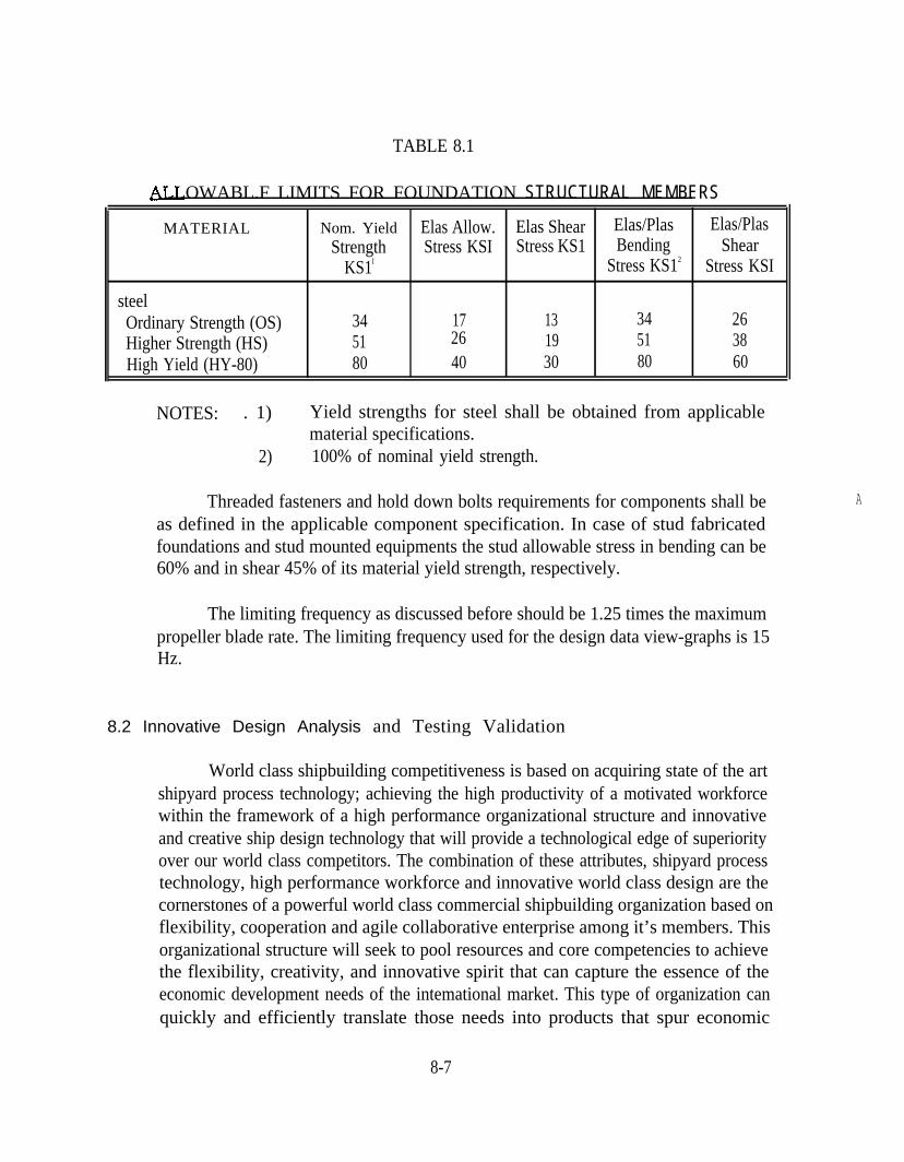
TABLE 8.1
OWABL.F LIMITS FOR FOUNDATION STRUCTURAL MEMBERS
MATERIAL Nom. Yield Elas Allow. Elas Shear Elas/Plas Elas/PlasStrength Stress KSI Stress KS1 Bending Shear
KS1l Stress KS12 Stress KSI
steelOrdinary Strength (OS) 34 17 13 34 26Higher Strength (HS) 51 26 19 51 38High Yield (HY-80) 80 40 30 80 60
NOTES: . 1) Yield strengths for steel shall be obtained from applicablematerial specifications.
2) 100% of nominal yield strength.
Threaded fasteners and hold down bolts requirements for components shall beas defined in the applicable component specification. In case of stud fabricatedfoundations and stud mounted equipments the stud allowable stress in bending can be60% and in shear 45% of its material yield strength, respectively.
The limiting frequency as discussed before should be 1.25 times the maximumpropeller blade rate. The limiting frequency used for the design data view-graphs is 15Hz.
8.2 Innovative Design Analysis and Testing Validation
World class shipbuilding competitiveness is based on acquiring state of the artshipyard process technology; achieving the high productivity of a motivated workforcewithin the framework of a high performance organizational structure and innovativeand creative ship design technology that will provide a technological edge of superiorityover our world class competitors. The combination of these attributes, shipyard processtechnology, high performance workforce and innovative world class design are thecornerstones of a powerful world class commercial shipbuilding organization based onflexibility, cooperation and agile collaborative enterprise among it’s members. Thisorganizational structure will seek to pool resources and core competencies to achievethe flexibility, creativity, and innovative spirit that can capture the essence of theeconomic development needs of the intemational market. This type of organization canquickly and efficiently translate those needs into products that spur economic
A
8-7

development within the world transportation markets. Critical ingredients to worldclass shipbuilding as it applies to design, manufacturing and cost competitiveness are:
●
●
●
●
●
●
●
●
Producibility InnovationCreativityTechnologyDesignManufacturingShipbuilding ProcessWorkforce Development
A strategy that will support long term innovation, that will underpin world classcompetitiveness is the ability to provide the proper technical validation for innovativeconcepts through analysis and testing verification for system cost and performancegoals and attributes.
A well thought out strategy for innovative development is articulated in the ShipStructure Committee’s (SSC) Long Range Research Plan. The plan formulationdescribed in figure 8.1 reviews trends and projections, investigates novel technologicalopportunities, identifies promising materials and fabrication systems, characterizespromising platform applications and the need for technology beyond the state of the artand develops the appropriate and desirable research and development that can beverified by analysis and testing.
8-8
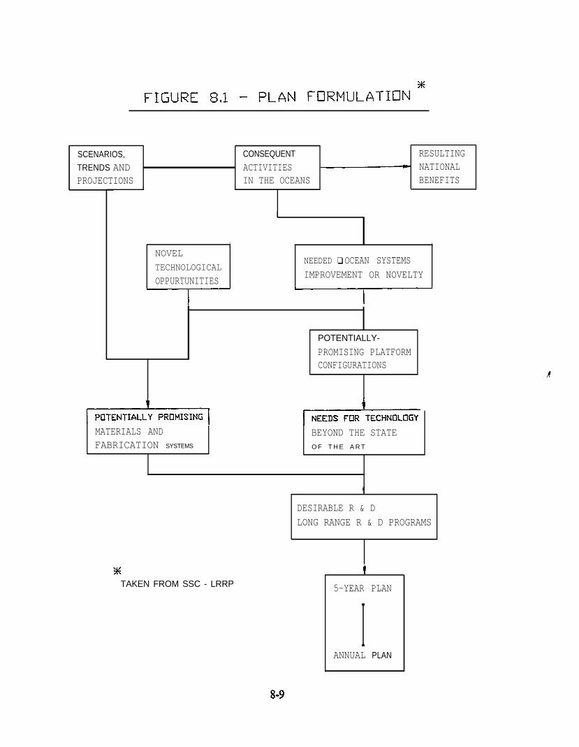
SCENARIOS, CONSEQUENT
TRENDS AND ACTIVITIESPROJECTIONS IN THE OCEANS
RESULTINGNATIONALBENEFITS
I 1
L
, 1 I i
NOVEL
TECHNOLOGICALNEEDED ❑ OCEAN SYSTEMS
OPPURTUNITIESIMPROVEMENT OR NOVELTY
POTENTIALLY-
PROMISING PLATFORMCONFIGURATIONS
MATERIALS AND BEYOND THE STATEFABRICATION SYSTEMS O F T H E A R T
i
TAKEN FROM SSC - LRRP
f
DESIRABLE R & DLONG RANGE R & D PROGRAMS
5-YEAR PLAN
IANNUAL PLAN
Cutting edge technology must be based on well founded and documentedresearch and development in order to provide assurance and acceptance of thetechnology by the industry. Furthermore, application of the results of research earnedthroughout development is a drawn out process that takes time and significant resourcesto implement in practical shipbuilding applications. There has been a significantresearch and development effort over the last 40 years that has been sponsored by theShip Structure Committee (SSC) that will help to provide a first principles approach tothe development of innovative structure and, consequently, foundation design. In theinterest of providing a rational basis to ship structure design the SSC - Long RangeResearch Plan identifies goal areas for the research they sponsor i.e. Loads, Responses,Materials, Fabrication, Reliability and Design Methods. See table 8.2 for the moredefined set of research areas regularly investigated upon which innovative and creativedesign changes for ship structures and foundations may be based. With appropriateresearch conducted to establish loads and the response of structure, the choice ofmaterials and fabrication techniques for unique designs, can be evaluated for reliabilityand safety. Appropriate design methods have been developed that can assist thedesigner in achieving acceptance by the Navy and/or commercial classflcation agenciesfor unique and innovative designs.
TABLE 8.2
plan for theShip Structure Committee
Goal Area 1: Loads● Non-Linear Effects● Experimental Models● Seaway Representation● Ice Loads● Load Combinations
Goal Area 2 Response● Ultimate Strength of Ship Structures● Responses to Transient Loads● Analytical Techniques for Predicting Structural Responses● Structural Responses to Collision and Grounding Loads
Goal Area 3: Materials● Marine Concrete Development● Development of Composites for Marine Utilization
8-10
Goal Area 4: Fabrication● Weld Inspection Methods and Criteria● Design for Production● Improved Welding Methods, Equipment and Consumables● Rational Regulatory Requirements● Technology Transfer/Diffusion
Goal Area 5: Reliability● Formulation of a Reliability Model● Data Feedback into Reliability Model
Goal Area 6: Design Methods● “Rational” Ship Design Process● Ship Vibration - Improved Parameter Definition, Criteria and Calculation
Methods● Fatigue of Ship Structural Elements, Criteria Design Methods and Structural
Detailing
Innovative Design solutions that provide the basis for resolving world classshipbuilding transportation problems is dependent on our understanding of the worldseconomic conditions and the resulting transportation needs that must be satisfiedthrough innovative design. In order to have a fundamental strategy for designinnovation, the designer should target likely candidates that offer solutions to identifiedproblems. Such a strategy should embody the following elements characterized in table8.3.
Forecasting should be conducted within the context of an understanding of thestate of international cooperation (scenarios for forecasts). Global trends provideinsight to innovative alternatives. Pervasive trends offer problems for long termsolutions. Promising technology offers the opportunity to exploit new discoveries toresolve old and new problems. Technical developments in manufacturing provide aninnovative means to improve competitiveness. Finally an internationally competitiveworkforce will employ innovative design solutions to traditional problems within thecontext of a new invigorating labor-management paradigm.
8-11

TABLE 8.3
ovative Competitiveness
Forecasting :
● Forecasting for 10 to 20 years are very riskypolitical whimEconomic, social or technological surprise
● Long lead time in the use of new knowledgeScientific research takes 16 years to implementGestation Period -6 to 8 years - Merchant ShipsPreliminary Design to commissioning -3 to 5 YearsNavy Ships -5 to 8 Years
Scenarios for Forecasts:
A -- High Interdependence - Global CooperationB -- Moderate Interdependence -, Most Probable CooperationC - Break Between Developed and Developing CountriesD - Break Between Developed Nations - Protectionism
Trends:● Technological Innovations● Resource Availability● Trends - Ship Platforms and Populations● political Trends● Legal Trends● Economic Trends● Military Trends● Environmental Trends
Pervasive Trends:● Rising Cost of Energy● Increasing Scarcity of Key Minerals● Increasing World Shipbuiltig Competition● Degeneration of US Commercial Shipping● Maintenance or Increasing Naval Force● Increasing Operations in Cold Waters
8-12
● Larger Vessels
Promising Technology :● Computer Technology● Computer Aided Manufacturing● Statistical - Parametric Methods
Failure AnalysisReliability and RiskSeaway Description
● Structural Condition Monitoring● Lifetime Cost Optimization in Design● Maintenance Cost Optimization in Operation● Advanced Information Exchange● Advanced Education and Training● New Sources of Scarce Minerals● Advanced Environmental Prediction
Promising Manufacturing Systems:● Electronically Controlled Robotics● Agile Manufacturing● Enhanced Accuracy Control - 99% Outfitting
Internationally Competitive Workforce:● Motivated Workforce● Cross-Trade Training - Shipyard Mechanic● New Labor - Management Paradigm
Innovative design if properly conducted and verified by acceptable analysis andtesting validation should be accepted for use by the worlds classification societies. Ideasmust be translated to real products in order to provide the competitive edge our U.S.shipbuilding industry requires. Our shipbuilding industry should capitalize on thesignificant investments made in technology research and development over the last 40years to revitalize our shipbuilding industry.
8.3 Design Methodology
Develop Preliminary Design Sketch & Integrate With Ship:The designer selects anappropriate foundation configuration to suit the particular installation based on vendorfurnished equipment information (VFI), equipment shipboard location and preliminaryscantlings selection. One of the 27 representative foundation designs and 18 standard
8-13
method mounts described in section 9.0 may be used as a guide to develop the initialconfiguration. Preliminary scantling selection for commercial ships can be done usingthe design data tables in section 9.0.
Once a foundation configuration is selected, an initial sketch showing the shipstructure and ship systems that impact on the foundation is developed. The designershould conduct the interference check with ship systems composites at this initial stage.At this point consideration should also be given to the preferred methods as describedin producibility recommendations and cost saving guidelines. Once the initial sketch isdeveloped, design validation through standard design or engineering analysis mayproceed. The design validation of the proposed foundation through quantitative reviewshould be conducted by a engineer trained in ship structure and foundation design.
validation Thr osigns: During the course of development ofthis design manual a parametric approach to foundation design was developed and usedwhich drew upon a design philosophy of Standard Foundation Installations.
Foundation installation statistics reveal that the variety of combinations ofgeometries and equipment weights is limited and can be clearly defined. Utilization ofa parametric analysis approach provides solutions for broad ranges of possibilities atone time, rather than each time the possibility is encountered, which can b-e drawn uponlater to significantly reduce engineering and design time. Standard foundation designscould be developed which satisfy a wide variety of applications. In this design manual,design data tables and view-graphs for foundations are included in section 9.0 whichwould allow the engineer to quickly determine if a foundation sketch proposed by thedesigner is adequate enough by comparison, rather than by performing the detailedanalysis for the same scenario repeatedly.
The design data tables are generated for commercial applications. In case ofnaval ships where shock, nuclear blast, noise. and other criteria predominantly governthe foundation design, foundation design validation through standard designs can stillbe accomplished by performing a parametric approach to foundation analysis andobtaining standard design tables for foundations based on the navy ship requirementsand specifications. This task is beyond the scope of this design manual, butrecommendations in Appendix B can be a good starting point.
- To validate the initial foundation design the engineer can verify the foundationgeometries and scantling sizes with design data tables for adequacy, provided therequirements, specifications and allowables are similar to that used in this designmanual. If the requirements and allowables vary then the engineer can scale the
8-14
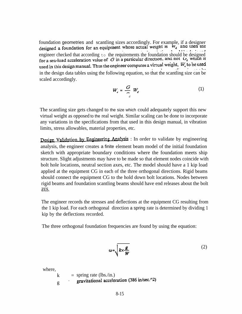
foundation geometries and scantling sizes accordingly. For example, if a designer
engineer checked that according to the requirements the foundation should be designed
in the design data tables using the following equation, so that the scantling size can bescaled accordingly.
d
(1)
The scantling size gets changed to the size which could adequately support this newvirtual weight as opposed to the real weight. Similar scaling can be done to incorporateany variations in the specifications from that used in this design manual, in vibrationlimits, stress allowables, material properties, etc.
: In order to validate by engineering
analysis, the engineer creates a finite element beam model of the initial foundationsketch with appropriate boundary conditions where the foundation meets shipstructure. Slight adjustments may have to be made so that element nodes coincide withbolt hole locations, neutral section axes, etc. The model should have a 1 kip loadapplied at the equipment CG in each of the three orthogonal directions. Rigid beamsshould connect the equipment CG to the hold down bolt locations. Nodes betweenrigid beams and foundation scantling beams should have end releases about the boltaxis.
The engineer records the stresses and deflections at the equipment CG resulting fromthe 1 kip load. For each orthogonal direction a spring rate is determined by dividing 1kip by the deflections recorded.
The three orthogonal foundation frequencies are found by using the equation:
where,k =g =
(2)
spring rate (lbs./in.)
8-15
W = weight of equipment + 1/2 foundation weight in lbs.
The “g-loading” that the foundation must support must be determined at this time anddepends on whether shock or sea loading requirements apply.
A. For shock design of U.S. Navy combatants, the lower of the acceleration
using the equipment weight, mounting location and shock direction as inputs forformulas given in DDS-072-1 (confidential).
Vo is determined using formulas given in DDS-072-1 and varies depending onequipment weight, mounting location, shock direction, and whether theequipment can tolerate slight yielding of foundation members. Velocity-governed “g” shock loadings (referred to as GVO) are given by the equation:
(3)
where,V o= the maximum shock velocity as given in DDS-072- 1 (in./seC.).w= the frequency of the foundation and equipment in the direction
being analyzed (rad./sec.)
B. For foundation design of commercial ships, the maximum accelerationproduced by sea loading is very rarely greater than three “g’s”, including thenormal one “g” of gravity.
be used in the following equation to determine shock stresses, replacing seaload “g”
should be used to calculate seaload-induced stresses and also scale the values based onthe ratio of the equipment weight plus 1/2 the foundation weight to the 1 kip load.
(4)
where,=
=
G =Seaload
unitload
Max stress in foundation due to sea loadsMax stress in foundation under unit load (1000 lbs.)Worst ship’s motions accelerations due to sea loads
8-16
w =cqpt+ 1/2fdn Equipment weight + half the foundation weight in lbsw =
unit load The unit load (1000 lbs.) applied to the FEA model
The shock or seaload stresses should then be compared with allowable stresses todetermine if the foundation meets strength requirements.
A. Foralignment-critical equipment on shock-governed foundations the allowablematerial stress is 100% of the material yield strength. Allowable shear stresses are 60%of the material yield strength.
For non-alignment-critical equipment on shock-governed foundations the allowablestress is 200% of the material yield strength. Allowable shear stresses are 120% of thematerial yield strength.
B. For commercial ship foundations being checked for strength to resist ship’smotions forces, the allowable stress is often 50-80% of the material yield stress. Theallowable shear stress is often 30-48% of the material yield stress.
8-17
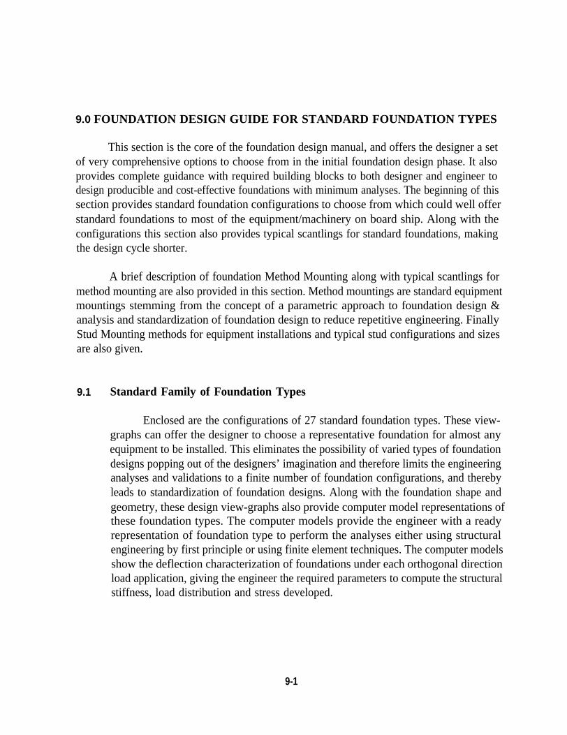
9.0 FOUNDATION DESIGN GUIDE FOR STANDARD FOUNDATION TYPES
This section is the core of the foundation design manual, and offers the designer a setof very comprehensive options to choose from in the initial foundation design phase. It alsoprovides complete guidance with required building blocks to both designer and engineer todesign producible and cost-effective foundations with minimum analyses. The beginning of thissection provides standard foundation configurations to choose from which could well offerstandard foundations to most of the equipment/machinery on board ship. Along with theconfigurations this section also provides typical scantlings for standard foundations, makingthe design cycle shorter.
A brief description of foundation Method Mounting along with typical scantlings formethod mounting are also provided in this section. Method mountings are standard equipmentmountings stemming from the concept of a parametric approach to foundation design &analysis and standardization of foundation design to reduce repetitive engineering. FinallyStud Mounting methods for equipment installations and typical stud configurations and sizesare also given.
9.1 Standard Family of Foundation Types
Enclosed are the configurations of 27 standard foundation types. These view-graphs can offer the designer to choose a representative foundation for almost anyequipment to be installed. This eliminates the possibility of varied types of foundationdesigns popping out of the designers’ imagination and therefore limits the engineeringanalyses and validations to a finite number of foundation configurations, and therebyleads to standardization of foundation designs. Along with the foundation shape andgeometry, these design view-graphs also provide computer model representations ofthese foundation types. The computer models provide the engineer with a readyrepresentation of foundation type to perform the analyses either using structuralengineering by first principle or using finite element techniques. The computer modelsshow the deflection characterization of foundations under each orthogonal directionload application, giving the engineer the required parameters to compute the structuralstiffness, load distribution and stress developed.
9-1
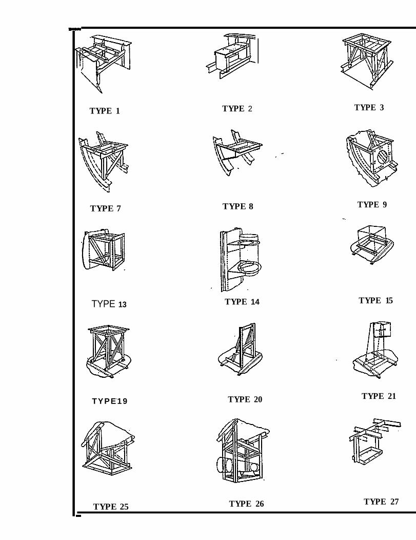
TYPE 1
TYPE 7
TYPE 13
TYPE-19
TYPE 2
TYPE 8
TYPE 14
TYPE 20
TYPE 3
TYPE 9
TYPE 15
TYPE 21
TYPE 25 TYPE 26 TYPE 27
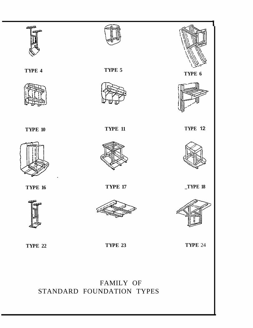
TYPE 4
TYPE 10
TYPE 16
TYPE 5
TYPE 11
TYPE 17
TYPE 22 TYPE 23
FAMILY OFSTANDARD FOUNDATION TYPES
TYPE 6
TYPE
_TYPE 18
TYPE 24
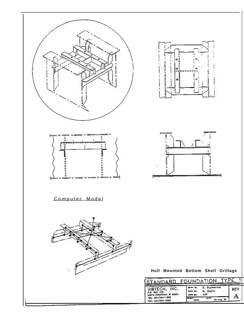
C o m p u t e r M o d e l
Hull Mounted Bottom Shell Gril lage
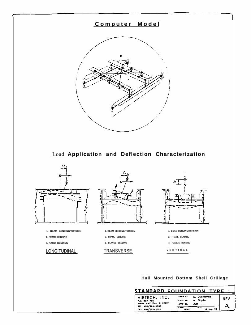
C o m p u t e r M o d e l
Load Application and Deflection Characterization
1. BEAM BENDING/TORSION
2. FRAME BENDING
3. FLANGE BENDING
LONGITUDINAL
1. BEAM BENDING/TORSION 1. BEAM BENDING/TCRSION
2. FRAME BENDING 2. FRAME BENDING
3. FLANGE BENDING 3. FLANGE BENDING
TRANSVERSE V E R T l C A L
Hull Mounted Bottom Shell Gril lage
S T A N D A R D FOUNDATION TYPE 1

C o m p u t e r M o d e l
Hull Mounted Bottom Shell Frame
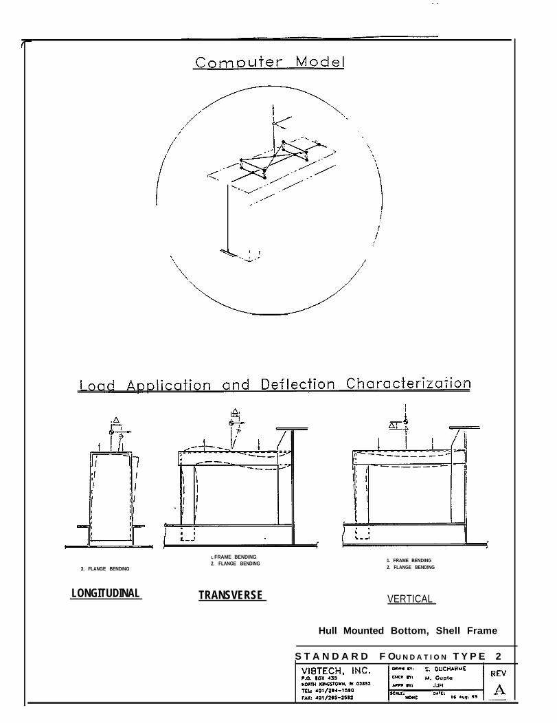
3. FLANGE BENDING
LONGITUDINAL
L FRAME BENDING2. FLANGE BENDING
TRANSVERSE
1. FRAME BENDING2. FLANGE BENDING
VERTICAL
Hull Mounted Bottom, Shell Frame
S T A N D A R D F OU N D A T I O N T Y P E 2
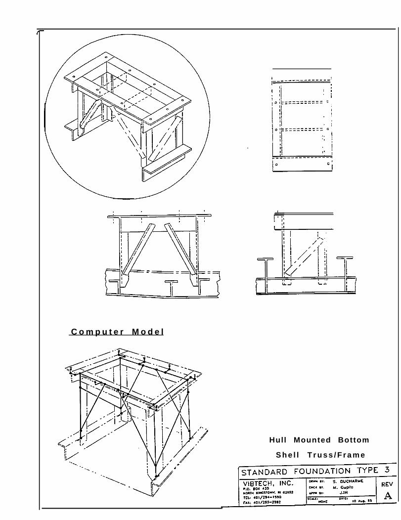
C o m p u t e r M o d e l
Hull Mounted Bottom
S h e l l T r u s s / F r a m e
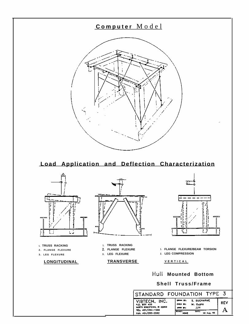
C o m p u t e r M o d e l
Load Appl icat ion and Def lect ion Character izat ion
I. TRUSS RACKING2. FLANGE FLEXURE
3. LEG FLEXURE
LONGITUDINAL
1.
2.3.
TRUSS RACKING
FLANGE FLEXURE
LEG FLEXURE
TRANSVERSE
1.
2.
FLANGE FLEXURE/BEAM TORSION
LEG COMPRESSION
V E R T I C A L
Mounted Bottom
S h e l l T r u s s / F r a m e
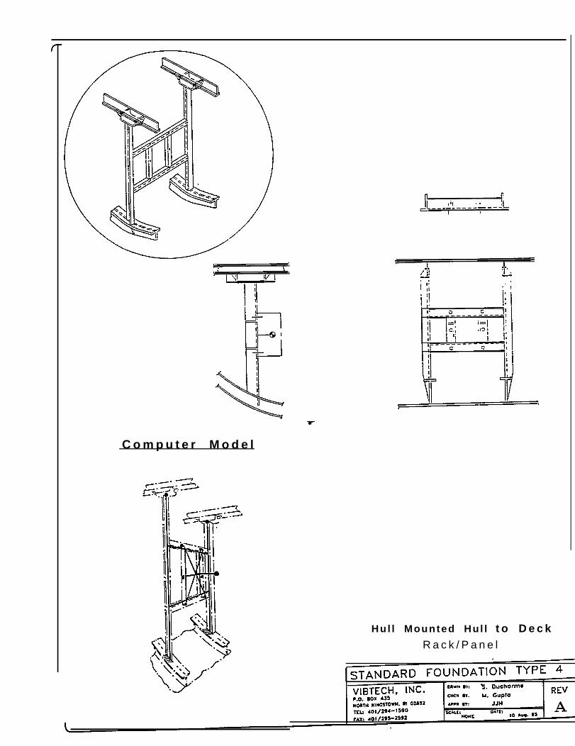
C o m p u t e r M o d e l
Hul l Mounted Hul l t o D e c kR a c k / P a n e l
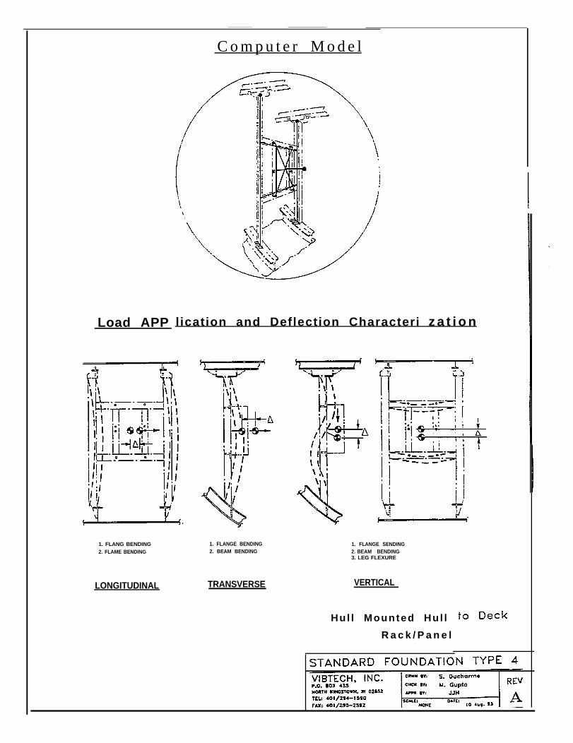
Load APP
C o m p u t e r M o d e l
l ication and Deflection Characteri z a t i o n
1. FLANG BENDING2. FLAME BENDING
LONGITUDINAL
1. FLANGE BENDING2. BEAM BENDlNG
TRANSVERSE
1. FLANGE SENDING2. BEAM BENDING3. LEG FLEXURE
VERTICAL
Hul l Mounted Hul l
R a c k / P a n e l
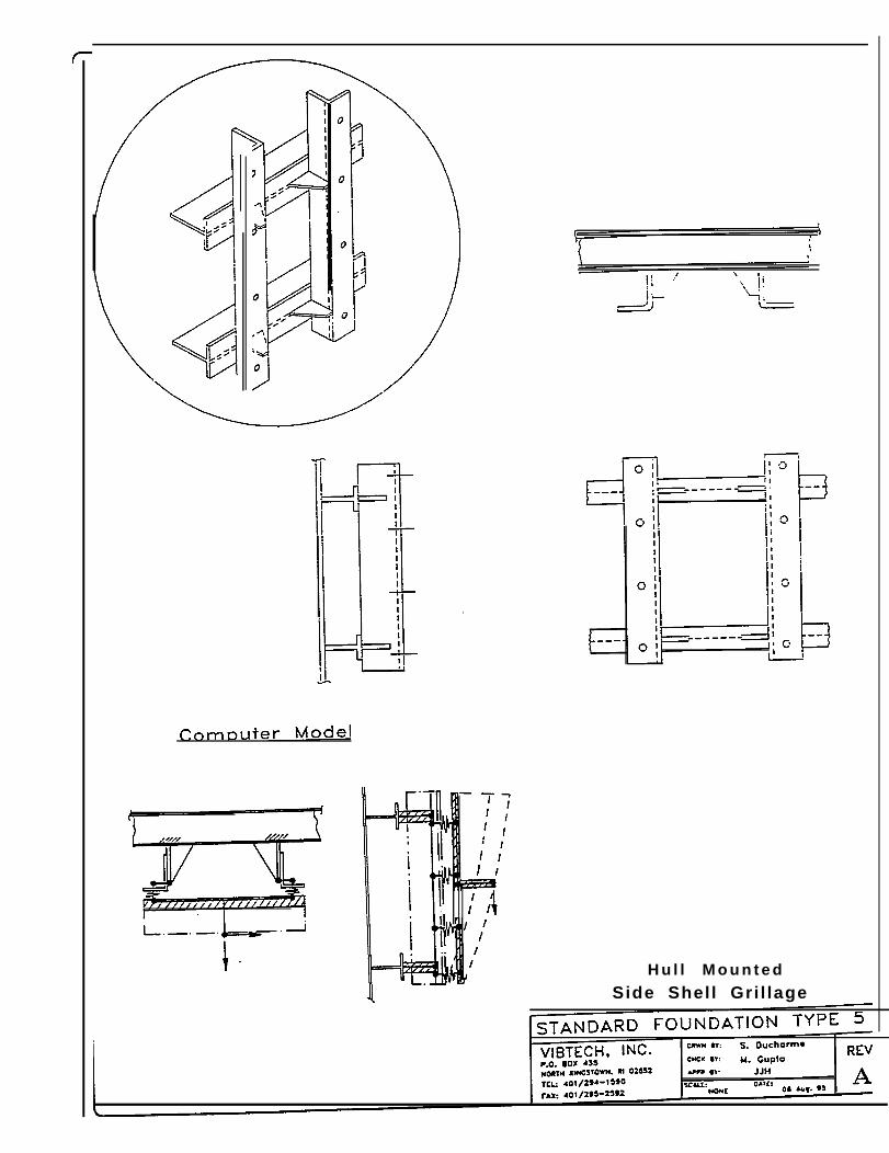
H u l l M o u n t e d
Side Shell Gri l lage
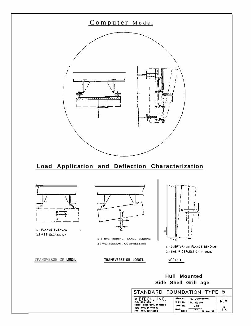
C o m p u t e r M o d e l
Load Application and Deflection Characterization
TRANSVERSE CR LONG’L
1 ] OVERTURNING FLANGE BENDING
2 ] WE3 TENSION / C O M P R E S S I O N
TRANSVERSE OR LONG’L
Hull MountedSide Shell Grill age
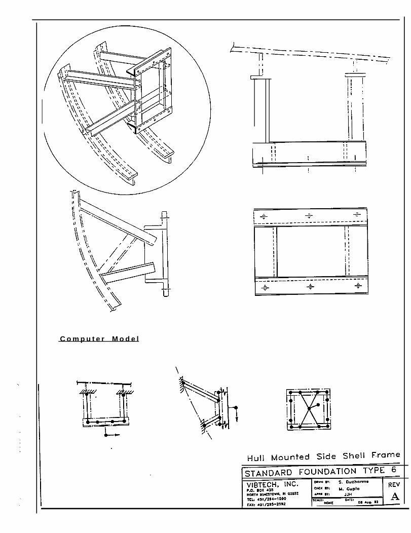
C o m p u t e r M o d e l
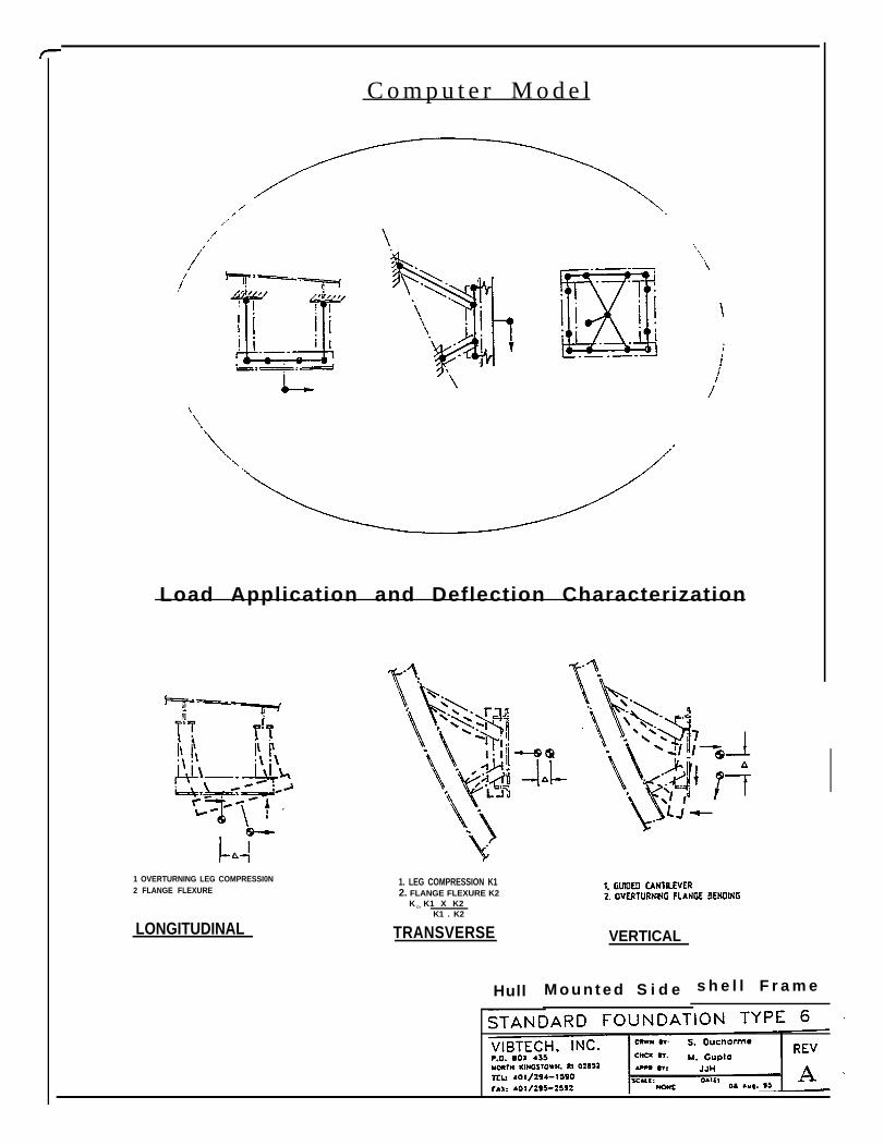
C o m p u t e r M o d e l
Load Application and Deflection Characterization
1 OVERTURNING LEG COMPRESSI0N2 FLANGE FLEXURE
LONGITUDINAL
1. LEG COMPRESSION K12. FLANGE FLEXURE K2
K C= K1 X K2K1 . K2
TRANSVERSE
Hull
VERTICAL
M o u n t e d S i d e s h e l l F r a m e
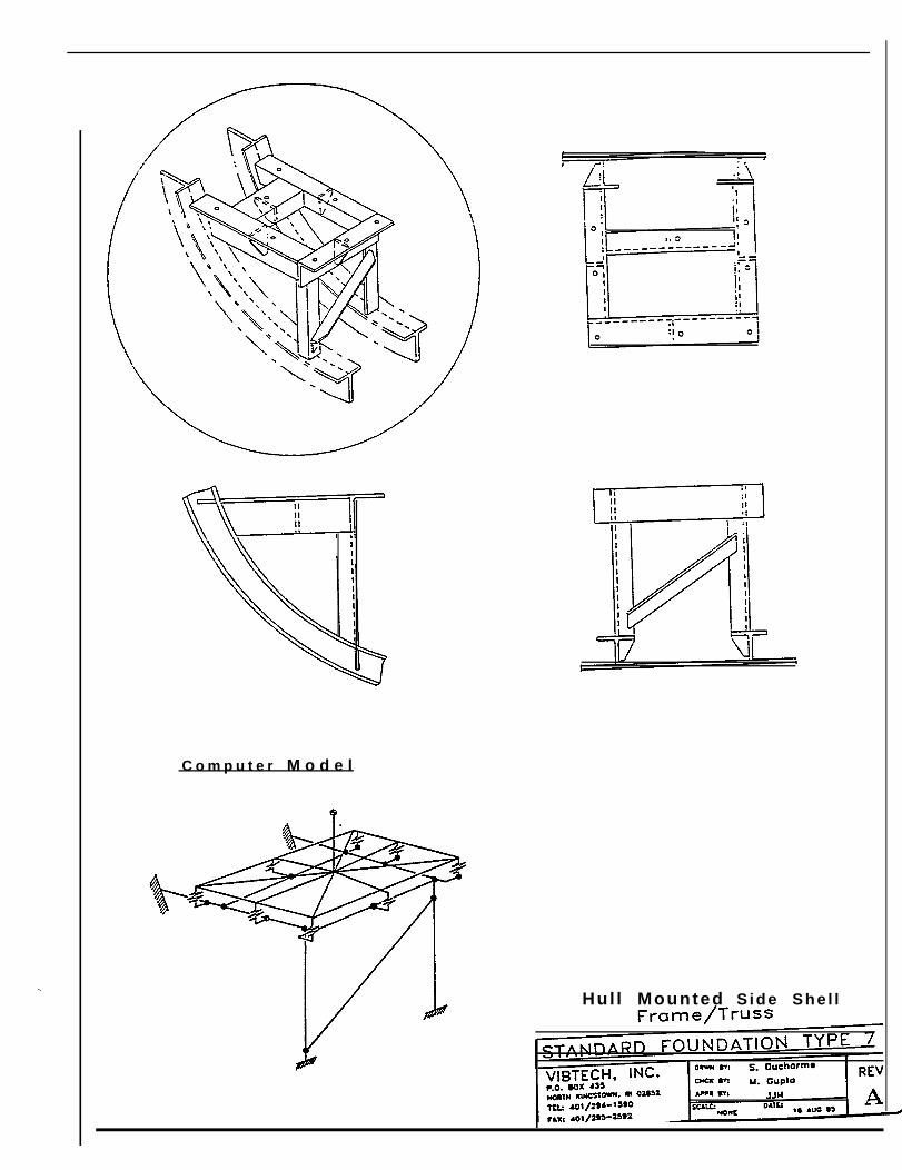
C o m p u t e r M o d e l
Hul l Mounted Side She l l
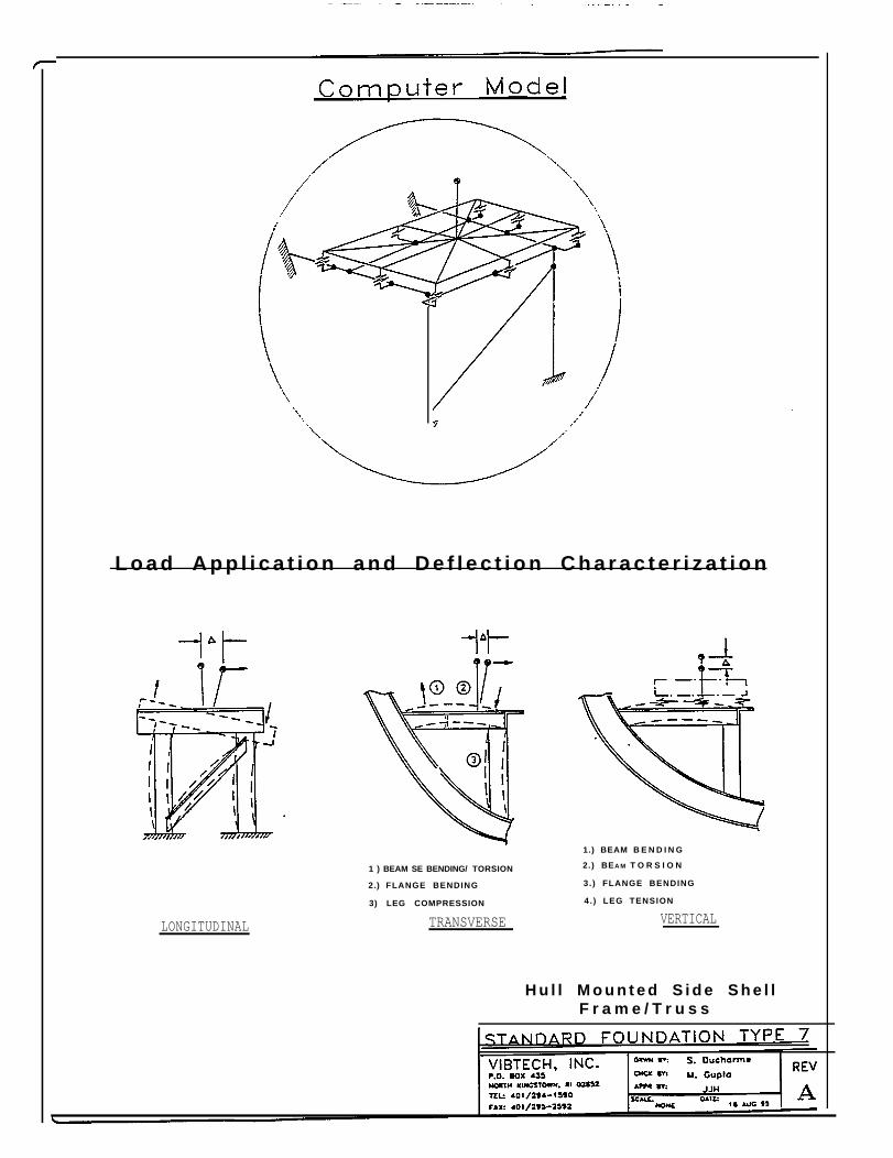
L o a d A p p l i c a t i o n a n d D e f l e c t i o n C h a r a c t e r i z a t i o n
LONGITUDINAL
1 ) BEAM SE BENDING/ TORSION
2.) FLANGE BENDING
3) LEG COMPRESSION
TRANSVERSE
1.) BEAM B E N D I N G
2.) BEA M T O R S I O N
3.) FLANGE BENDING
4. ) LEG TENSION
VERTICAL
H u l l M o u n t e d S i d e S h e l lF r a m e / T r u s s
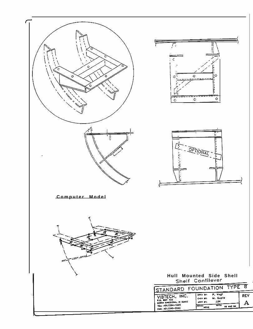
C o m p u t e r M o d e l
Hul l Mounted S ide She l l
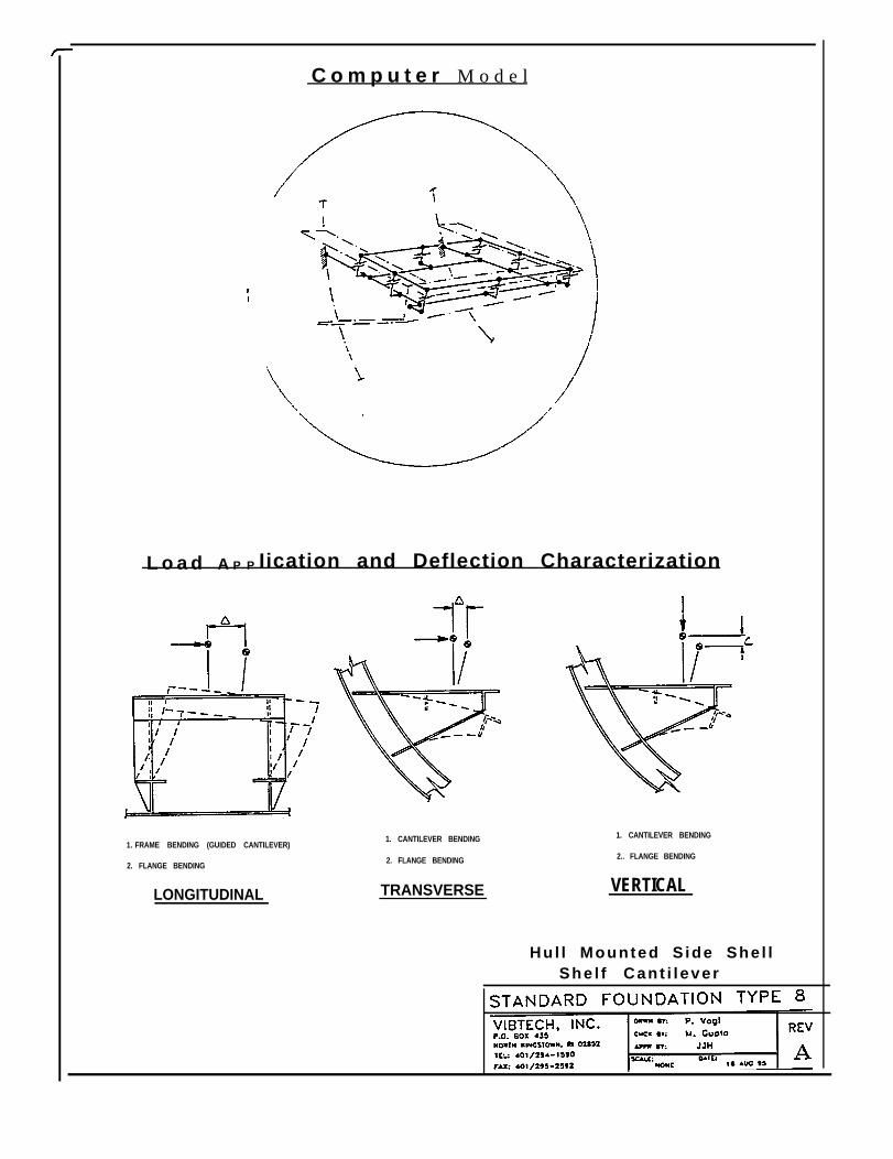
C o m p u t e r M o d e l
L o a d A P P Iication and Deflection Characterization
1. FRAME BENDING (GUIDED CANTILEVER)
2. FLANGE BENDING
LONGITUDINAL
1. CANTILEVER BENDING
2. FLANGE BENDING
TRANSVERSE
1. CANTILEVER BENDING
2.. FLANGE BENDING
VERTICAL
Hul l Mounted S ide She l lShe l f Cant i l ever
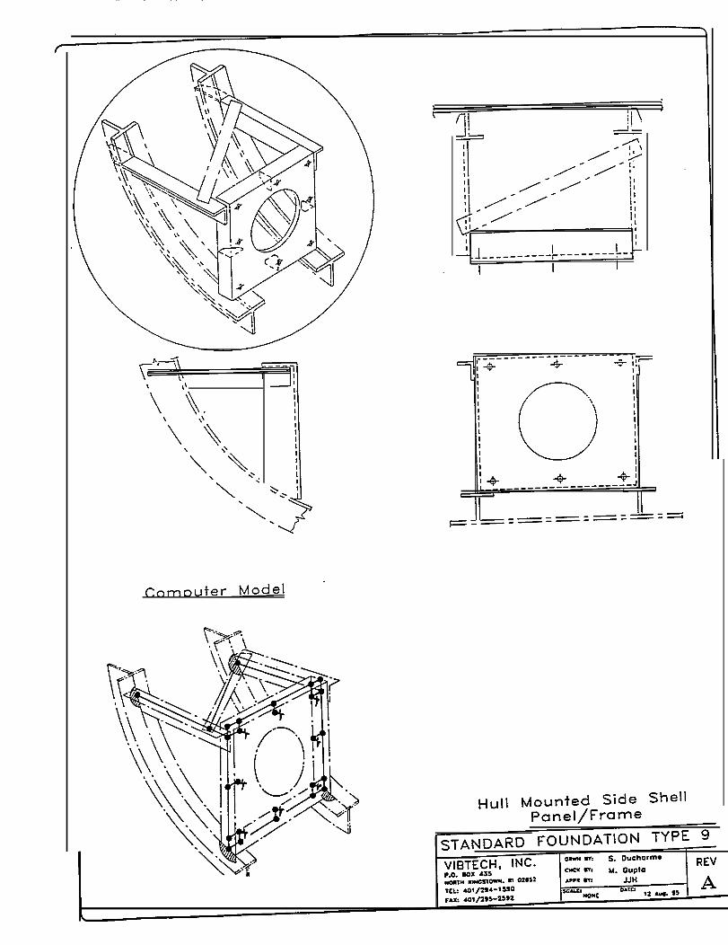
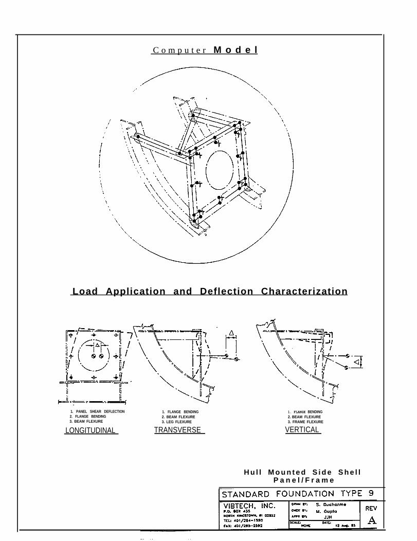
C o m p u t e r M o d e l
Load Application and Deflection Characterization
1. PANEL SHEAR DEFLECTION 1. FLANGE BENDING2. FLANGE BENDING 2. BEAM FLEXURE3. BEAM FLEXURE 3. LEG FLEXURE
LONGITUDINAL TRANSVERSE
1. FLANGE BENDING2. BEAM FLEXURE3. FRAME FLEXURE
VERTICAL
H u l l M o u n t e d S i d e S h e l lP a n e l / F r a m e
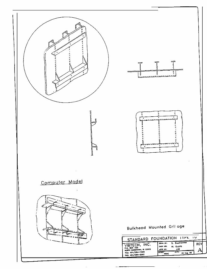
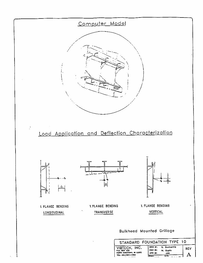
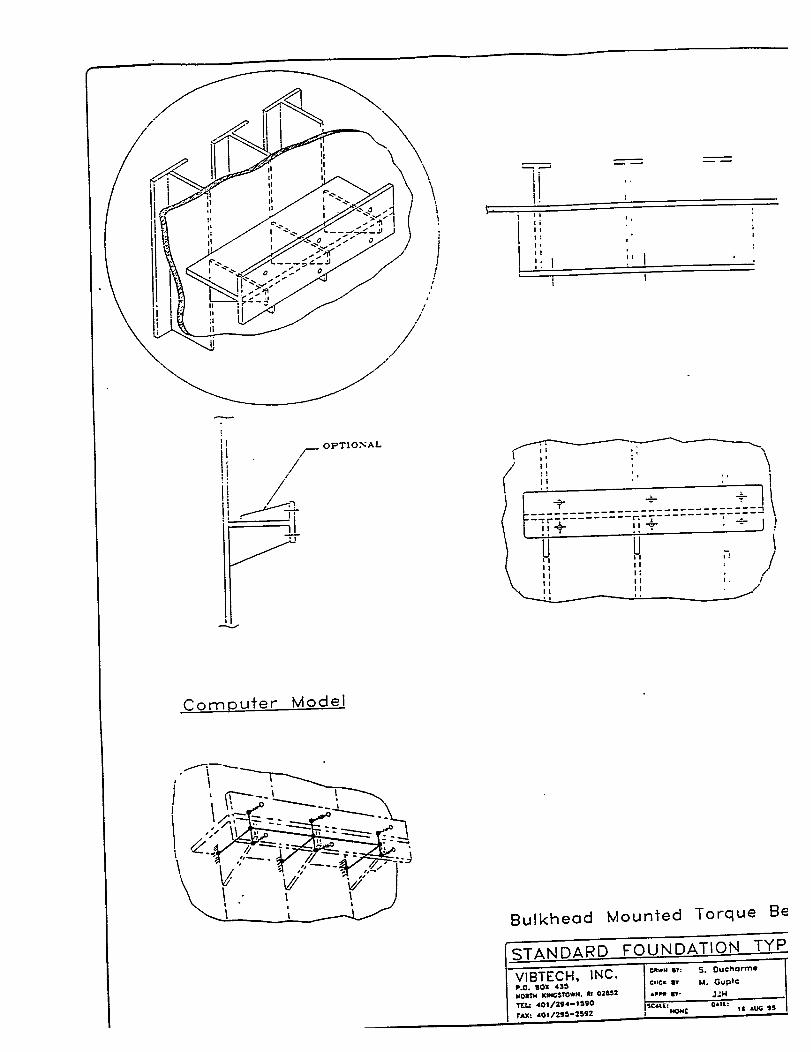
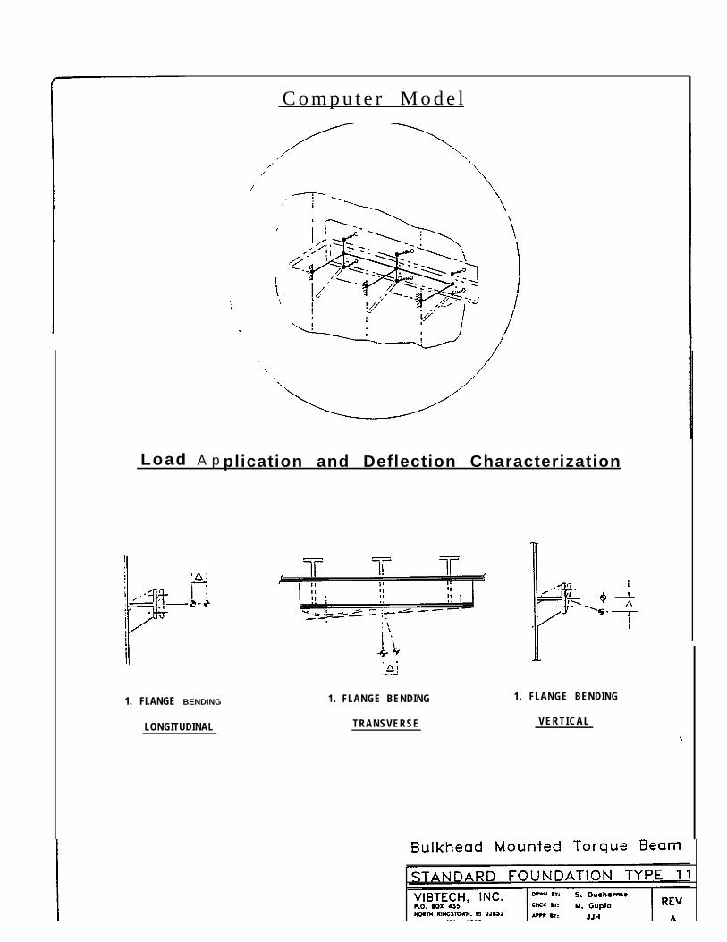
C o m p u t e r M o d e l
Load A p plication and Deflection Characterization
1. FLANGE BENDING
LONGITUDINAL
1. FLANGE BENDING
TRANSVERSE
1. FLANGE BENDING
VERTICAL
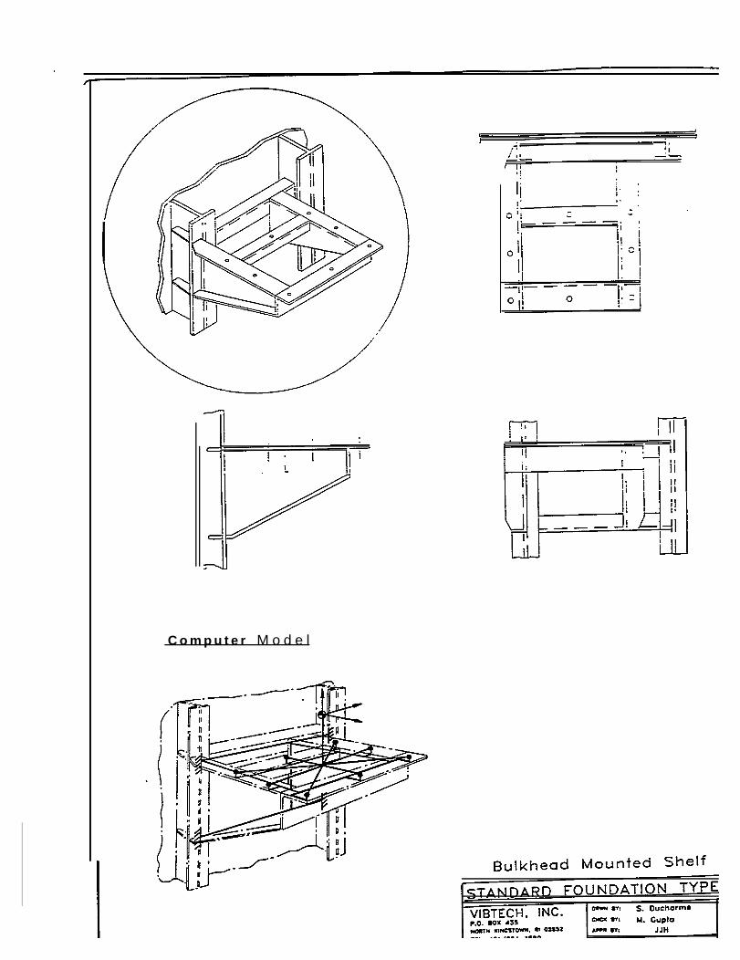
C o m p u t e r M o d e l
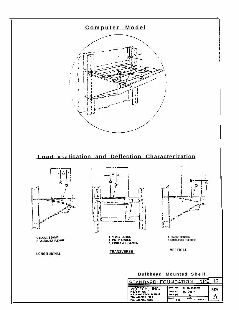
C o m p u t e r M o d e l
L o a d A P P Iication and Deflection Characterization
LONGITUDINALTRANSVERSE
1. FLANGE BENDING2. CANTILEVER FLEXURE
VERTICAL
B u l k h e a d M o u n t e d S h e l f
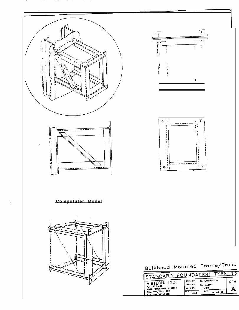
Compututer Model
I
I
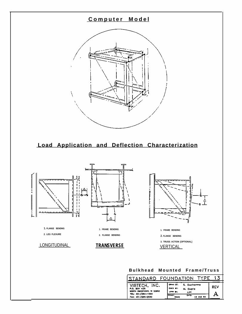
C o m p u t e r M o d e l
Load Application and Deflection Characterization
1. FLANGE BENDING 1. FRAME BENDING
2. LEG FLEXURE 2. FLANGE BENDING
LONGITUDINAL TRANSVERSE
1. FRAME BENDING
2. FLANGE BENDING
3. TRUSS ACTION [OPTIONAL]
VERTICAL
B u l k h e a d M o u n t e d F r a m e / T r u s s
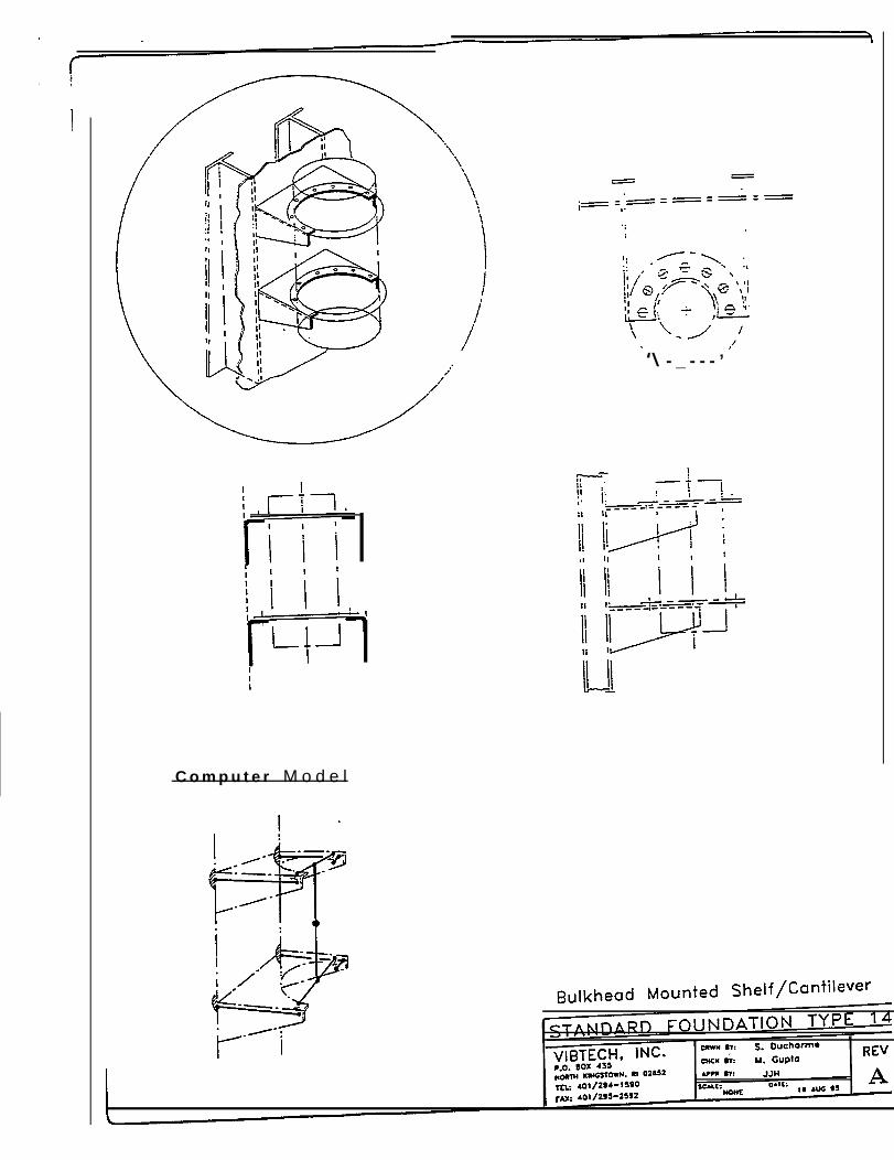
C o m p u t e r M o d e l
‘\ - _ - - - ’
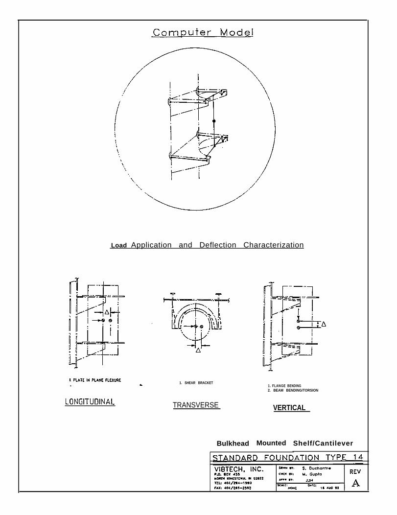
Load Application and Deflection Characterization
1. SHEAR BRACKET
TRANSVERSE
Bulkhead
1. FLANGE BENDING2. BEAM BENDING/TORSION
VERTICAL
Mounted Shelf/Cantilever
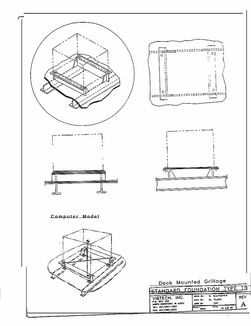
I
I
C o m p u t e r M o d e l
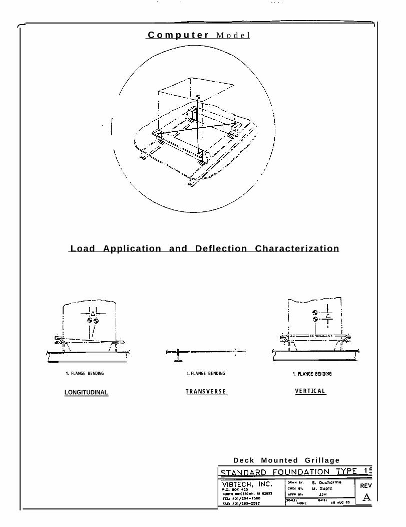
C o m p u t e r M o d e l
Load Application and Deflection Characterization
1. FLANGE BENDING
LONGITUDINAL
1. FLANGE BENDING
T R A N S V E R S E V E R T I C A L
D e c k M o u n t e d G r i l l a g e
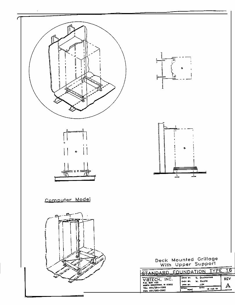
bI I
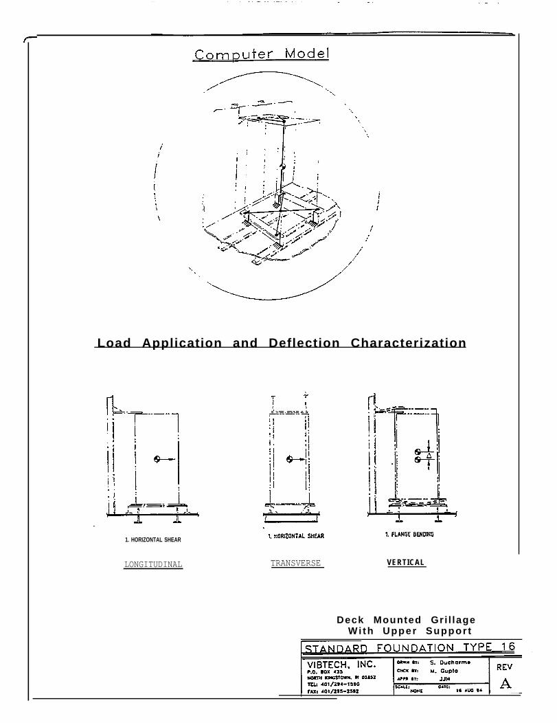
Load Application and Deflection Characterization
1. HORIZONTAL SHEAR
LONGITUDINAL TRANSVERSE VERTICAL
Deck Mounted Gri l lageWi th Upper Suppor t
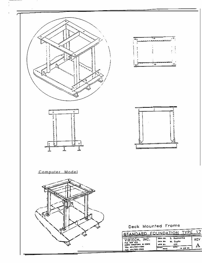
C o m p u t e r M o d e l
r
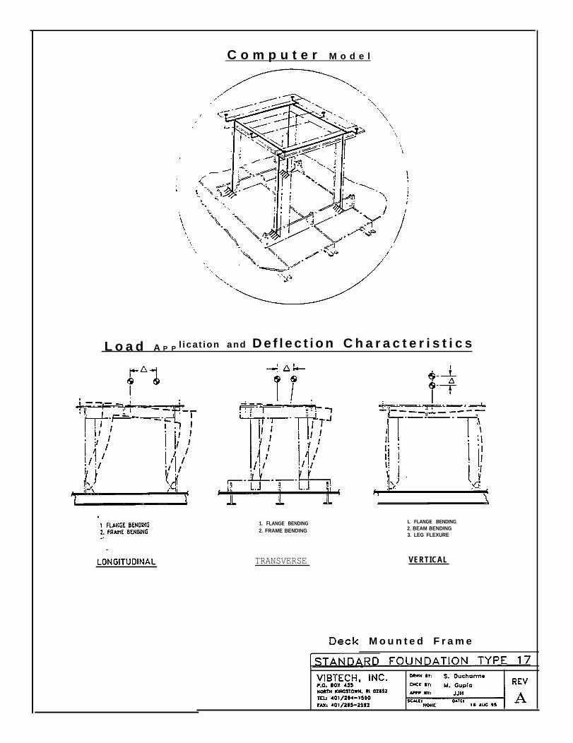
C o m p u t e r M o d e l
L o a d A P P l icat ion and D e f l e c t i o n C h a r a c t e r i s t i c s
1. FLANGE BENDING2. FRAME BENDING
TRANSVERSE
L FLANGE BENDING2. BEAM BENDING3. LEG FLEXURE
VERTICAL
M o u n t e d F r a m e
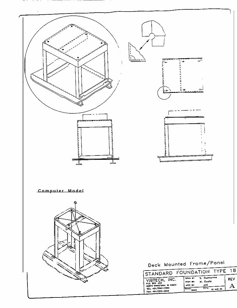
C o m p u t e r M o d e l

L o a d A P P Iication and Deflection Characterization
1. FLANGE BENDING2. FRAME BENDING3. LEG FLEXURE
LONGITUDINAL
1. FLANGE BENDING2. FRAME BENDING3. LEG FLEXURE
TRANSVERSE
L FLANGE BENDING2. BEAM BENDING3. LEG FLEXURE
VERTICAL
D e c k M o u n t e d F r a m e / P a n e l
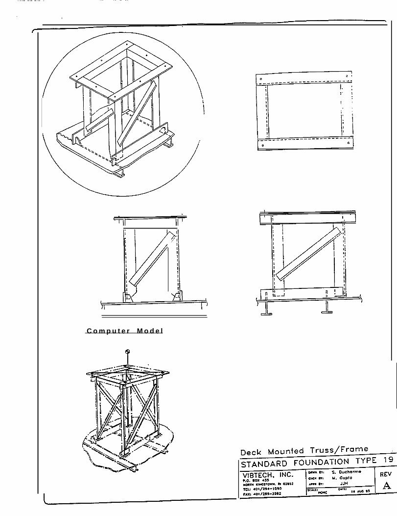
C o m p u t e r M o d e l
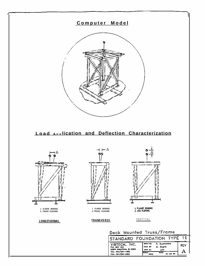
C o m p u t e r M o d e l
L o a d A P P Iication and Deflection Characterization
1. FLANGE BENDING2. TRUSS FLEXURE
LONGITUDINAL
L FLANGE BENDING2. TRUSS FLEXURE
TRANSVERSE VERTICAL
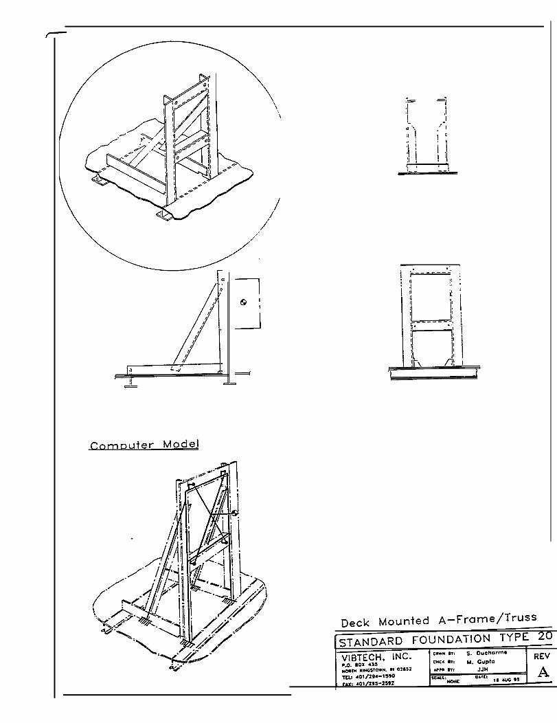
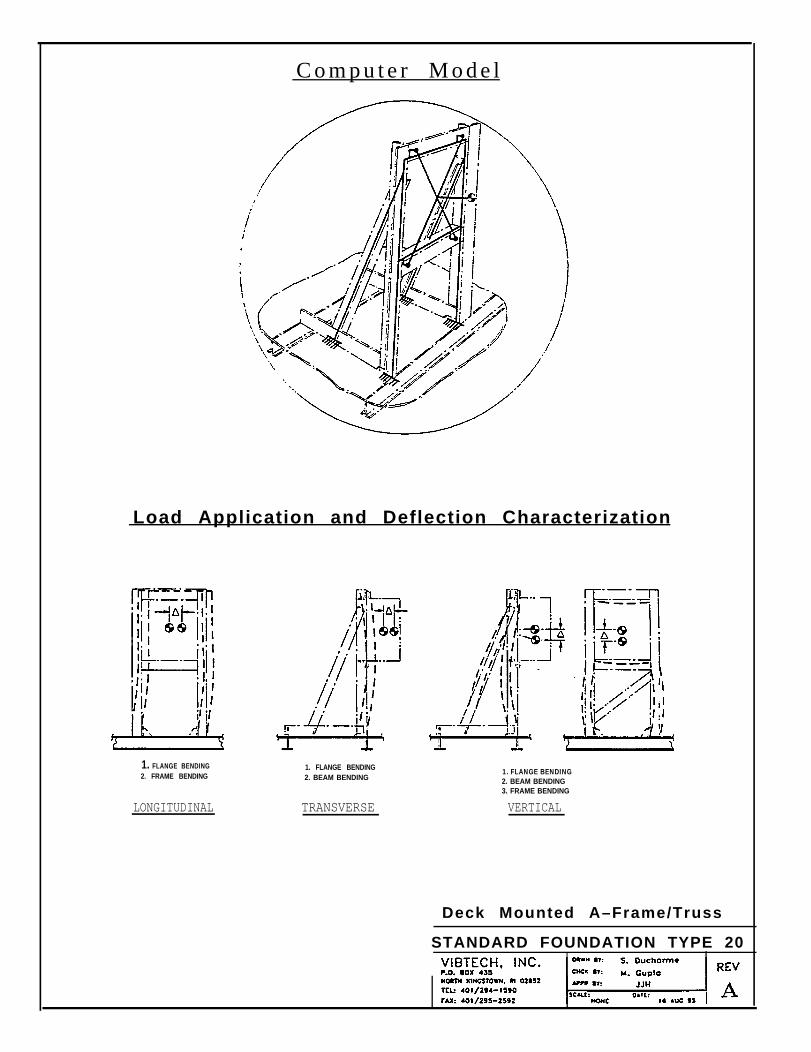
C o m p u t e r M o d e l
Load Application and Deflection Characterization
1. FLANGE BENDING 1. FLANGE BENDING2. FRAME BENDING 2. BEAM BENDING
LONGITUDINAL TRANSVERSE
1. FLANGE BENDING2. BEAM BENDING3. FRAME BENDING
VERTICAL
Deck Mounted A–Frame/Truss
STANDARD FOUNDATION TYPE 20
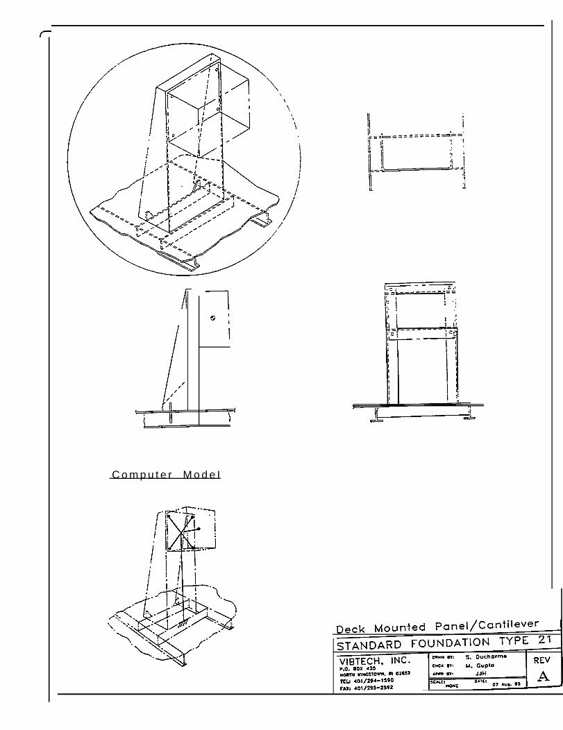
C o m p u t e r M o d e I
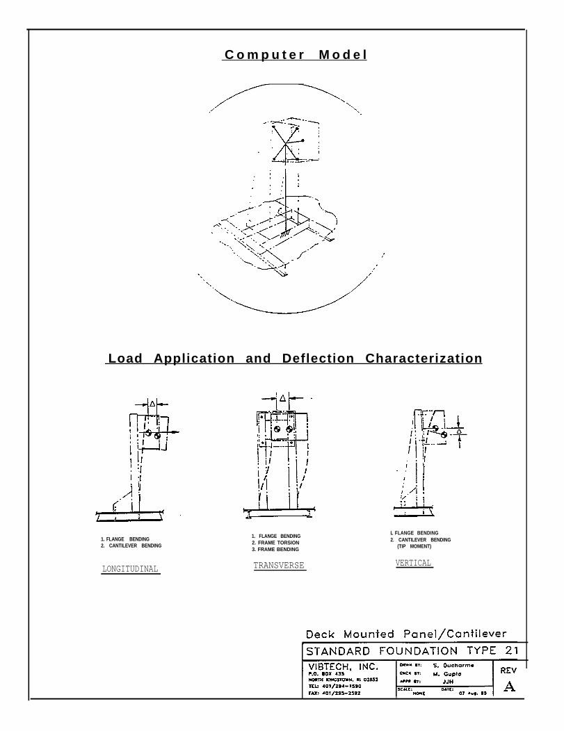
C o m p u t e r M o d e l
Load Application and Deflection Characterization
1. FLANGE BENDING2. CANTILEVER BENDING
LONGITUDINAL
1. FLANGE BENDING2. FRAME TORSION3. FRAME BENDING
TRANSVERSE
L FLANGE BENDING2. CANTILEVER BENDING
(TIP MOMENT)
VERTICAL
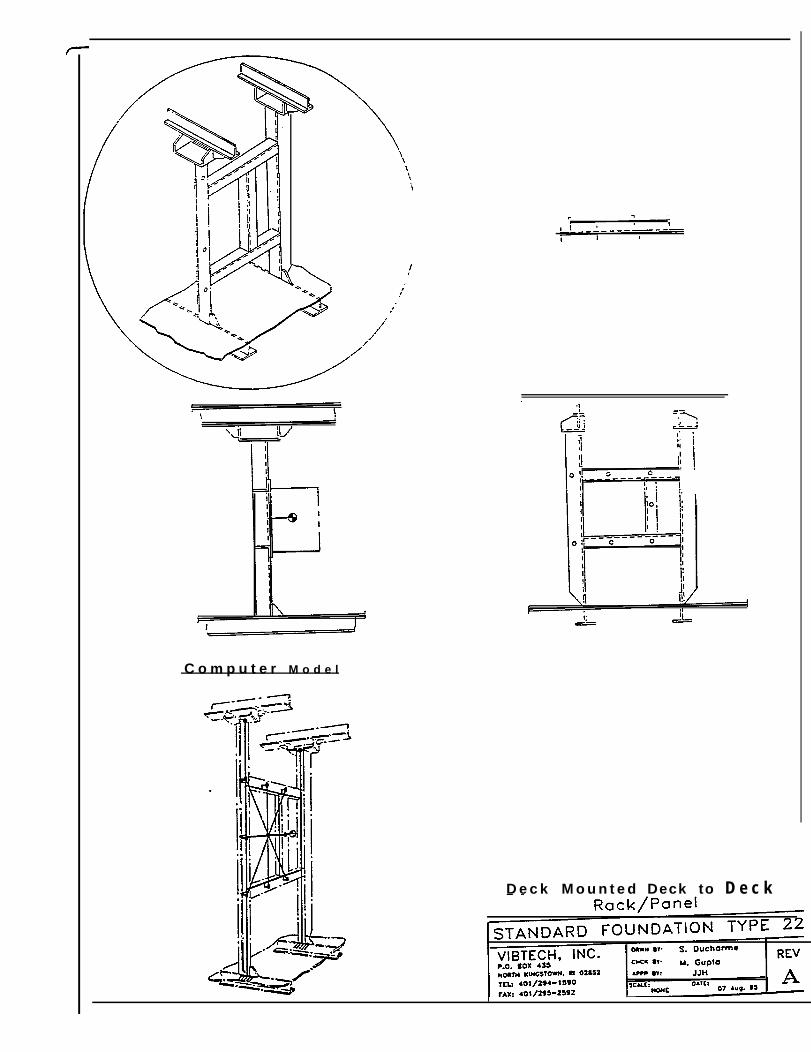
C o m p u t e r M o d e l
D e c k M o u n t e d Deck to D e c k

L o a d A P P Iication and Deflection Characterization
1. FLANGE BENDING2. BEAM BENDING3. LEG FLEXURE
LONGITUDINAL TRANSVERSE
1. FLANGE BENDING2. BEAM BENDING3. LEG FLEXURE
VERTICAL
D e c k M o u n t e d D e c k t oR a c k / P a n e l
Deck
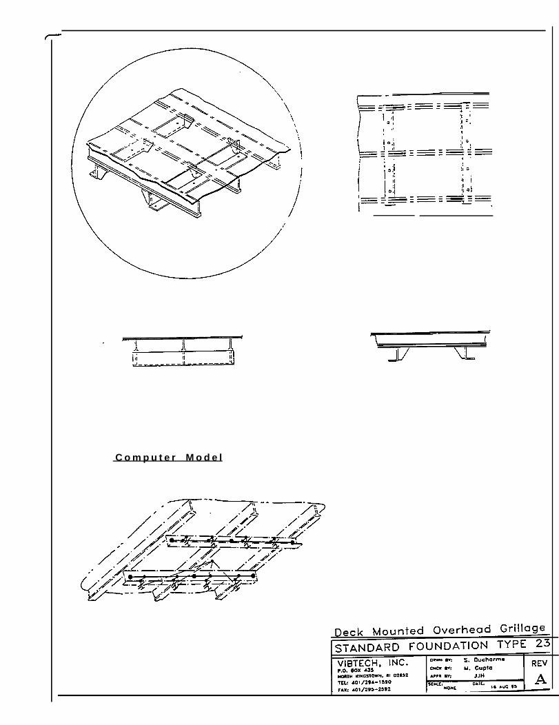
C o m p u t e r M o d e l
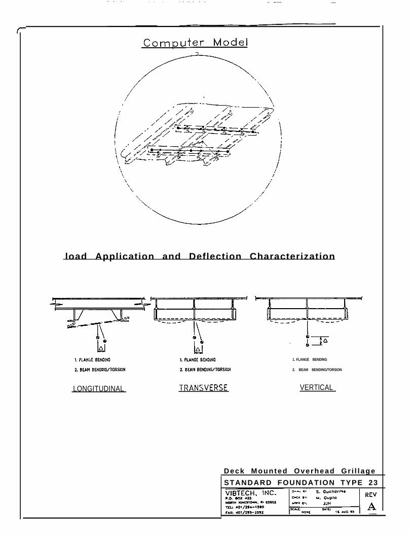
load Application and Deflection Characterization
LONGITUDINAL
1. FLANGE BENDING
2. BEAM BENDING/TORSION
VERTlCAL
Deck Mounted Overhead Gr i l l age
STANDARD FOUNDATION TYPE 23
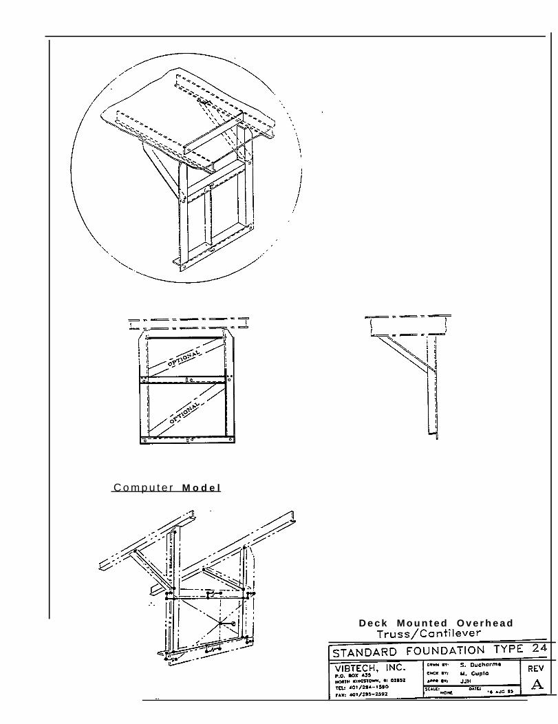
C o m p u t e r M o d e l
D e c k M o u n t e d O v e r h e a d
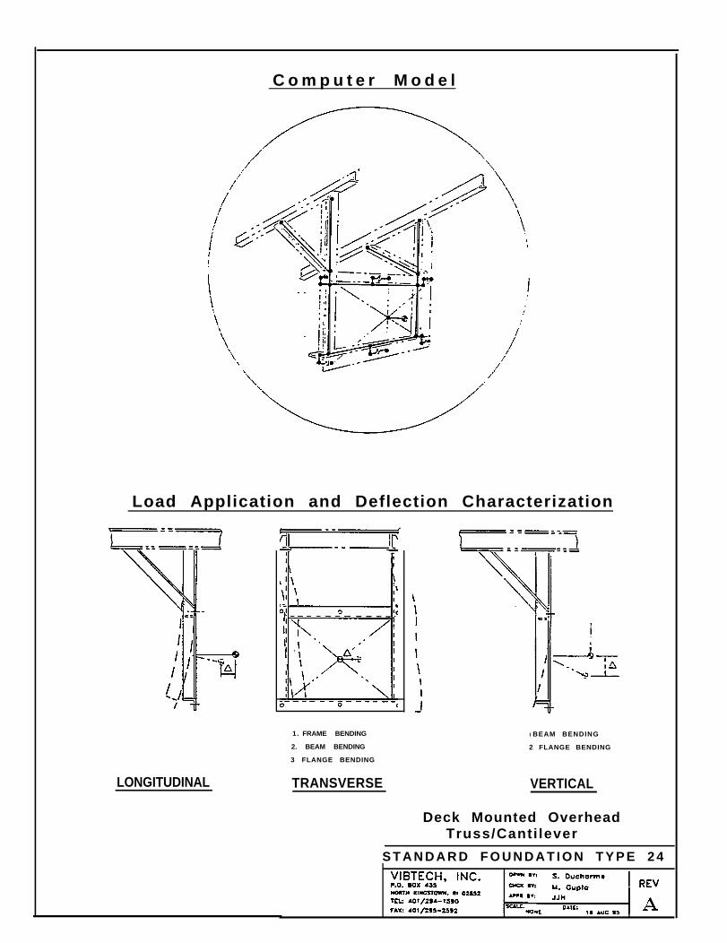
C o m p u t e r M o d e l
Load Application and Deflection Characterization
LONGITUDINAL
1. FRAME BENDING
2. BEAM BENDING
3 FLANGE BENDING
TRANSVERSE
I BEAM BENDING
2 FLANGE BENDING
VERTICAL
Deck Mounted OverheadTruss/Canti lever
S T A N D A R D F O U N D A T I O N T Y P E 2 4
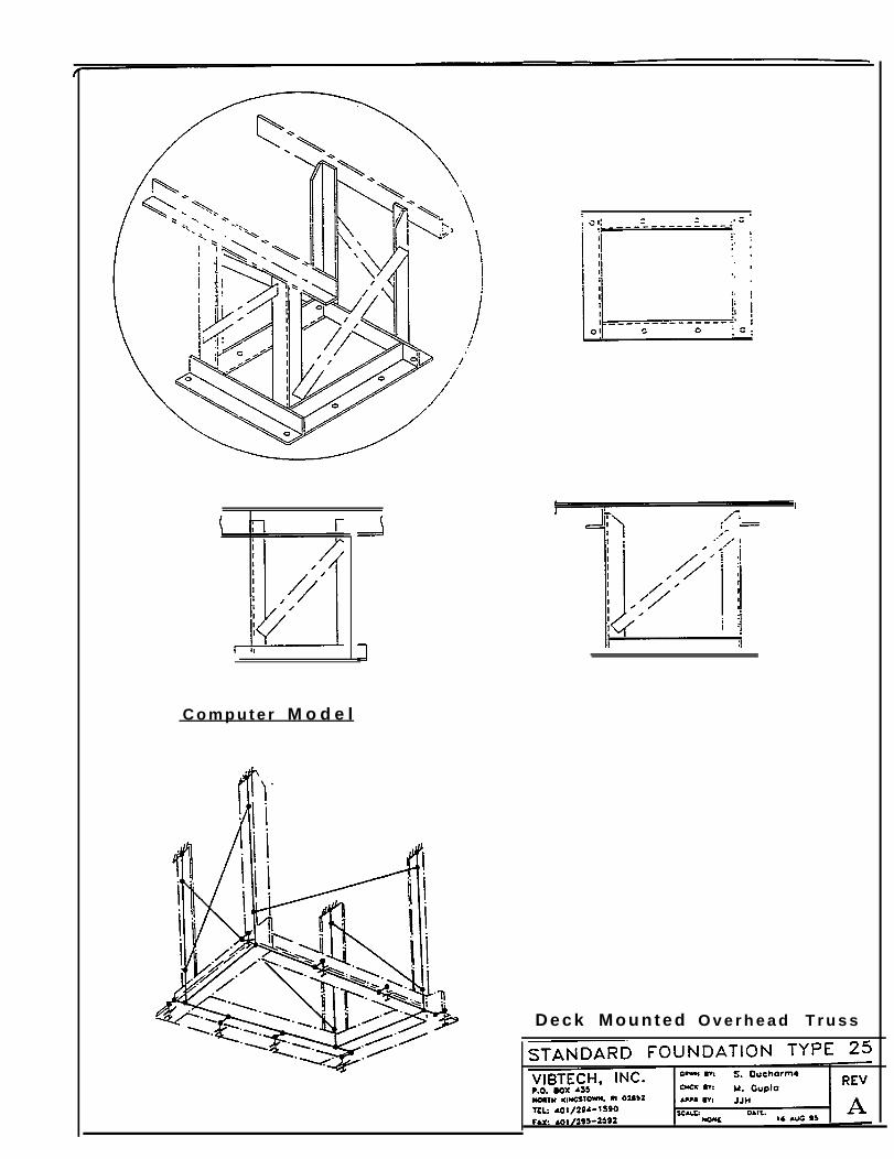
C o m p u t e r M o d e l
D e c k M o u n t e d O v e r h e a d T r u s s
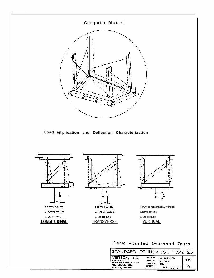
Computer M o d e l
Load ap plication and Deflection Characterization
LONGITUDINAL TRANSVERSE
1 FLANGE FLEXURE/BEAM TORSION
2. BEAM BENDING
3. LEG FLEXURE
VERTICAL
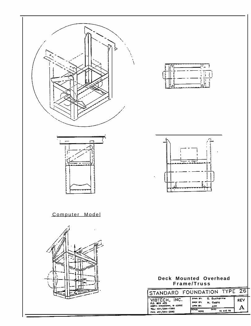
C o m p u t e r M o d e l
Deck Mounted OverheadF r a m e / T r u s s
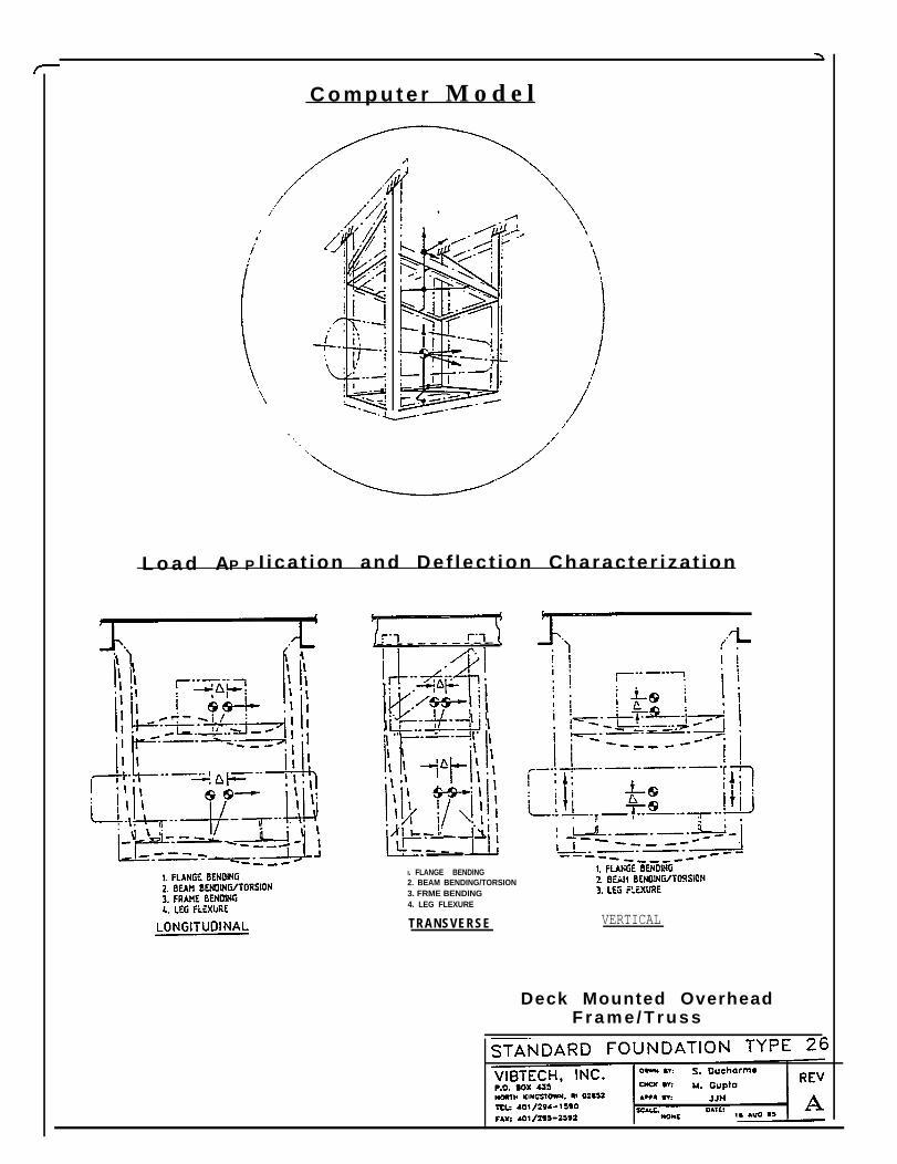
C o m p u t e r M o d e l
L o a d AP P I i ca t ion and Def lec t ion Character i za t ion
I. FLANGE BENDING2. BEAM BENDING/TORSION3. FRME BENDING4. LEG FLEXURE
TRANSVERSE VERTICAL
Deck Mounted OverheadF r a m e / T r u s s
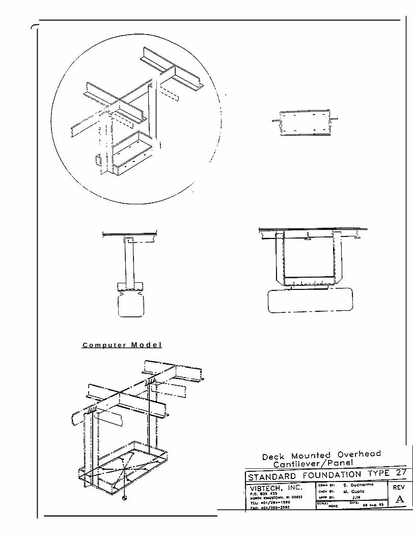
C o m p u t e r M o d e l
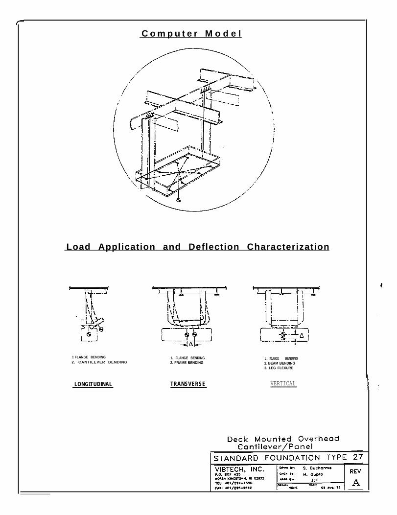
C o m p u t e r M o d e l
Load Application and Deflection Characterization
1 FLANGE BENDING2. CANTILEVER BENDING
LONGITUDINAL
1. FLANGE BENDING2. FRAME BENDING
TRANSVERSE
1. FLANGE BENDING2. BEAM BENDING3. LEG FLEXURE
VERTICAL
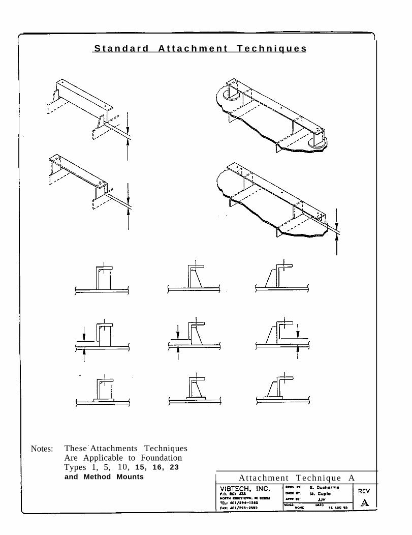
S t a n d a r d A t t a c h m e n t T e c h n i q u e s
Notes: These - Attachments TechniquesAre Applicable to FoundationTypes 1, 5, 10, 15, 16, 23and Method Mounts I Attachment Technique A
9.2 Typical Scantlings for Standard Foundations
Enclosed are design view-graphs & data tables for the 3 most frequently usedfoundation configurations. These design tables provide the scantling sizes forfoundations suitable for equipments having certain defined limits, capable of meetingnormal environmental, noise and vibration requirements. These design data tables werecomputed with a very conservative approach, the worst combination of sea-loads alongwith the worst orientation of foundation and minimum bolting attachments wereadopted. Described below is a generic procedure to use these design data tables forfoundation design:
● Obtain equipment information (VFI) of the equipment/machinery to beinstalled, equipment weight, height of CG (eccentricity) and bolting pattern arerequired. For grillages, mounting plate thickness information on which thefoundation will be attached, is required.
● Compute the ratio e/h, where e is the eccentricity and h is the spacing betweenextreme bolts in the direction of maximum seaway load. (See attached graphicalillustration)
● Compute the required load bearing capacity per bolting attachment by dividingthe equipment weight by the number of bolts given in the bolting pattern.
● The load bearing capacity per bolting attachment is checked off on the DesignData Table corresponding to the Mounting Plate thickness in case of grillages,or corresponding to Mounting Angle span length in case of frames/trusses, andthe minimum scantling size which gives the allowable load higher than therequired load bearing capacity is selected for mounting scantling.
● For frames/trusses compute the required load bearing capacity per leg bydividing the equipment weight by the number of legs required in the foundation.The minimum scantling size corresponding to the frame/truss leg length whichgives the allowable load higher than the required load bearing capacity per leg,is selected for foundation legs.
● Develop fret-cut foundation sketch with the foundation configuration and selectscantlings.
9-2
● Perform interference check.
● Re-develop the foundation sketch if required. Producibility and cost-savingmethods should be incorporated at every design step.
● Validate the final Foundation Design.
9-3
I
m o u n t i n g
GR LLAGE
Design Data of Limit Load in Lbs.
2.5x2 .5xl/40.5 I112 266 459 459 459
1 28 66 247 247 247
3x3x 1/40.5 112 262 449 449 449
1 28 66 242 242 242
3x3x3/8 0.5 113 266 887 965 966
1 2 8 6 7 2 2 2 5 2 0 5 2 0
0.5 113 266 866 1038 10363.5x3.5x3/8 1 28 67
217 485 558
4x4xl/2 0.5 113 267 889 1813 1813
I 1 I 28 67 I 2 2 2 I 5 1 5 968
EQPT
FRAME
Design Data of Limit Load in Lbs.
I 0.52 x 2 x 3 / 1 6
258
139
258
139
459
247
449
242
966
520
213 I 160 I 128
126 I 94 75
438 I 329 I 264
449 I 449 I 338
520 I 409 I 295
I Frame Leg Lenglh (in)Sizes (in.) 6 12 18 24 30 3 6
2 . 5 x 2 . 5 x l / 40 . 5 2CO0 1150 775 5 7 5 - - - - - -
1 1800 \ 1100 7 5 0 5 5 0 - - - - - -
3x3x l /4I
0 . 5 2 9 0 0 1 6 5 0 1 1 2 5 8 7 5 700 ---
1 2 6 5 0 ] 1 5 5 0 1 1 0 0 8 5 0 675 - I
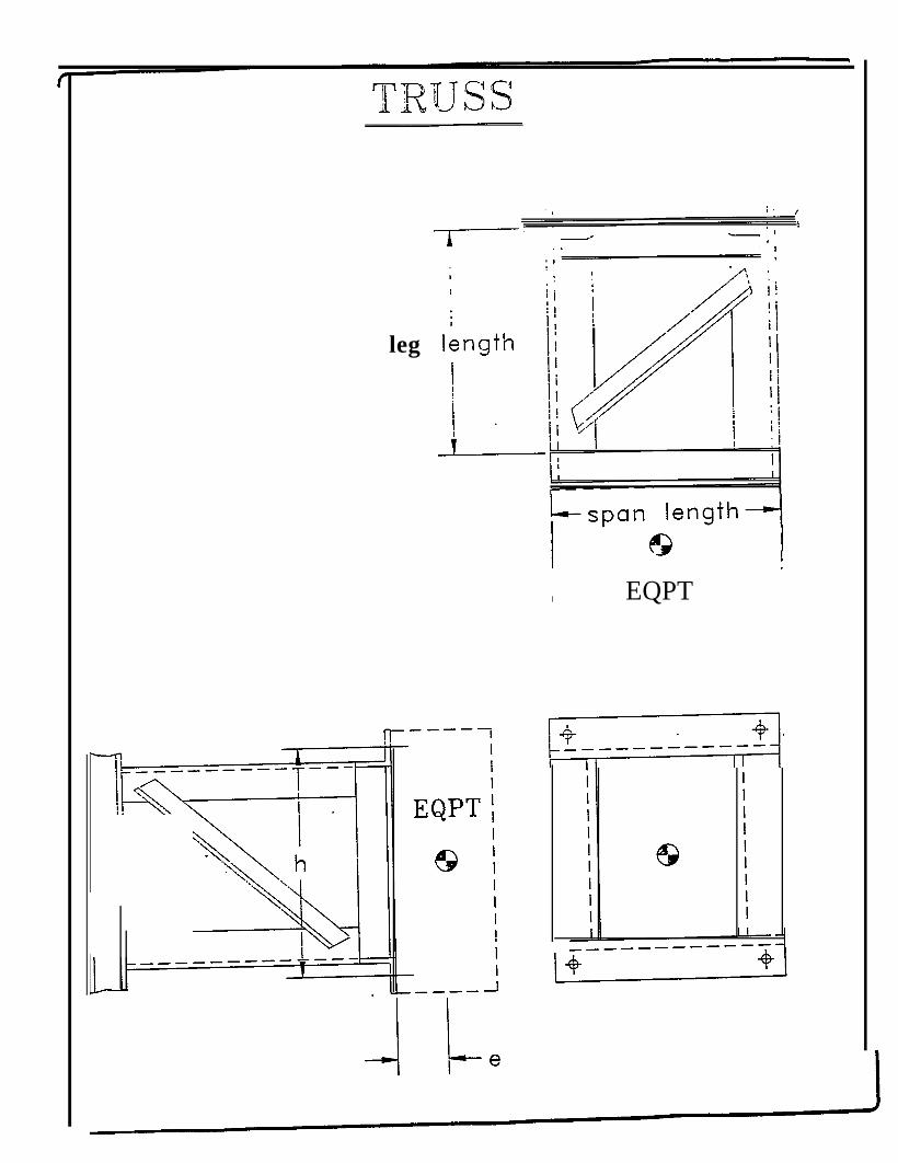
leg
I EQPT
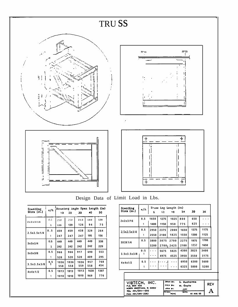
TRU
Design Data of
0.5 258 258 2 1 32 x 2 x 3 / 1 6
1 6 0 128
1 139 139 1 2 6 9 4 7 5
2 . 5 x 2 . 5 x 1 / 40 . 5 4 5 9 4 5 9 4 3 8 3 2 9 2 6 4
1 2 4 7 2 4 7 2 4 7 195 156
3x3x1/40.5 449 449 ‘ 449 449 338
1 242 242 242 242 229
3x3x3/8 0 . 5 9 6 6 9 6 6 9 1 7 6 9 0 5 5 3
1 5 2 0 5 2 0 5 2 0 4 0 9 2 9 5
0 . 5 1 0 3 6 1 0 3 6 ‘ 1 0 3 6 9 5 7 7 6 83 . 5 x 3 . 5 x 3 / 8 1
5 5 8 5 5 8 5 5 9 5 5 8 4 5 4
4 x 4 x 1 / 2 0 . 5 1 8 1 3 1813 1 8 1 3 1630 1307
1 1 0 1 0 1010 1010 9 6 9 7 7 6
ss
imit Load in Lbs.
0 . 5 1 6 5 0 2 x 2 x 3 / 1 6
1275 1 0 2 5 8 0 0 6 5 0 - - -
1 1400 1150 9 5 0 7 7 5 6 2 5 - - -
2.5x2.5x1/40 . 5 2 9 5 0 2 3 7 5 2 0 0 0 1 6 5 0 1375 1175
1 2 5 5 0 2 1 0 0 1 8 2 5 1 5 5 0 1300 1125
3 X 3 X 1 / 40 . 5
I
3 8 0 0 3 0 7 5 2 7 0 0 2 2 7 5 1975 1700
3 2 0 0 2 7 0 0 2 4 2 5 2 1 0 0 1850 1650
0 : 5 - - - 5 6 7 5 5 0 2 5 4 3 0 0 3 8 2 5 3 4 0 03 . 5 x 3 . 5 x 3 / 8 1 - - - 4 9 7 5 4 5 2 5 3 9 5 0 3 5 5 0 3 1 7 5
4 x 4 x l / 2 I I0 . 5 - - - - - - , - - - 6 9 5 0 6 3 0 0 5 6 0 0
1 - - - - - - - - - 6 3 2 5 5 8 0 0 5 2 0 0

9.3 Typical Configurations & Scantlings for Foundation Method Mounting
Method or standard mounting is based on the observation that equipmentmountings can be standardiized based on several factors:
● Where engineering methodology is applied in a consistent manner, consistentresults can be expected.
● Where equipment can be characterized by geometry, weight and boltingattachment design, then parametric analysis of these variables can yield standarddesigns suitable for equipment that are within the bounds of the parametriclimits.
● Parametric analysis of the equipment and mounting methods is comprehensiveand time consuming to ensure that all equipment falling within the parametriclimits imposed on a specific design can be mounted on the foundations withoutrequiring further analysis.
There are hundreds of lightweight power panels, controllers, transformers, (blackboxes), etc., for which a standard mounting approach could be used for installation.These designs are lightweight and cost effective because they are optimized usingproducibility design inputs and they are engineered to reduce welding to the minimumrequired. Thus standard mounting foundation solutions are suitable for equipmentwithin the defined weight limits and are capable of meeting normal environmental, noiseand vibration requirements.
Once having performed the generalized engineering and parametric analyses, theengineers selecting the proper standard mounting need only compare the particularequipment being supported to the standard mounting design parametric limits definedfor each design in order to select a suitable method. This, of course, will reduceengineering time to a minimum for these applications. The approach used in developingan engineering approach to standard mounting is as follows:
Characterize equipment to be supported. Statistics for equipment dimensions,i.e. height, width, depth, center of gravity (eccentricities), bolt patterndimensions, and equipment weight must be evaluated parametrically.
Develop computer/hand calculation math models to investigate each candidatestandard mounting method order to determine equipment geometry or weight
9 4
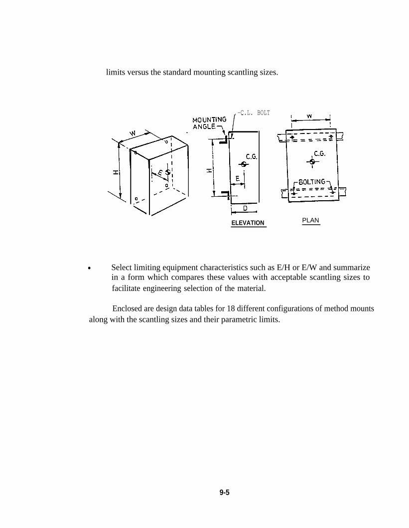
limits versus the standard mounting scantling sizes.
,-C.L. BOLT
ELEVATION PLAN
● Select limiting equipment characteristics such as E/H or E/W and summarizein a form which compares these values with acceptable scantling sizes tofacilitate engineering selection of the material.
Enclosed are design data tables for 18 different configurations of method mountsalong with the scantling sizes and their parametric limits.
9-5
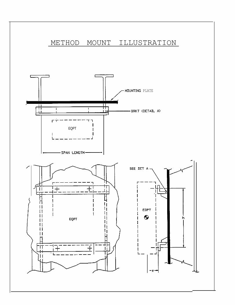
METHOD MOUNT ILLUSTRATION
PLATE
IEQPT I
I I
EQPT
SEE
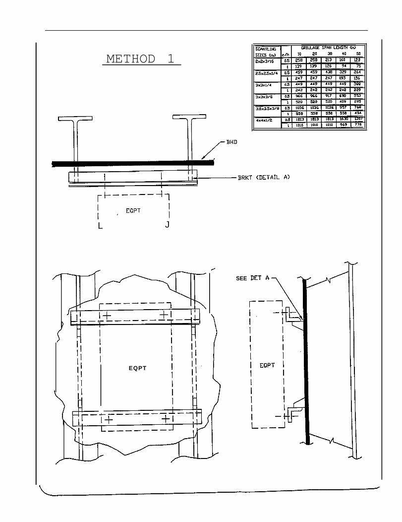
METHOD 1
IL J
EQPT
SEE
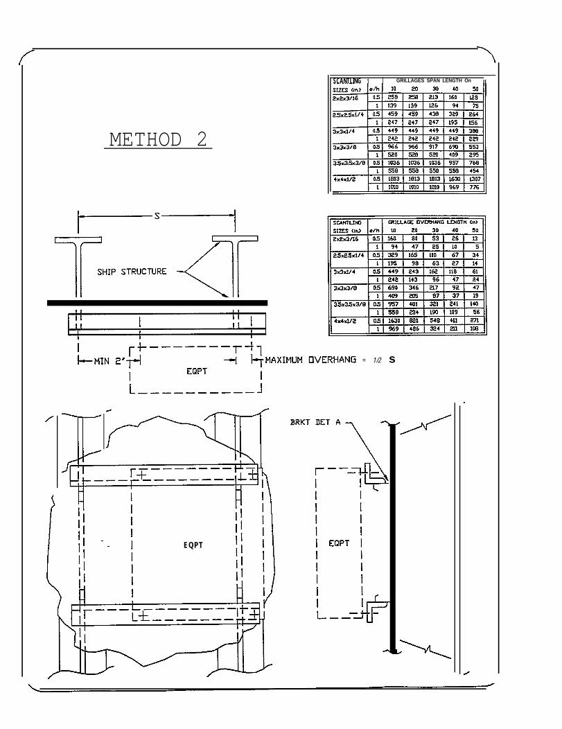
METHOD 2
EQPT
SCANTLING 1 I GRILLAGES SPAN LENGTH On II
= 1/2 s
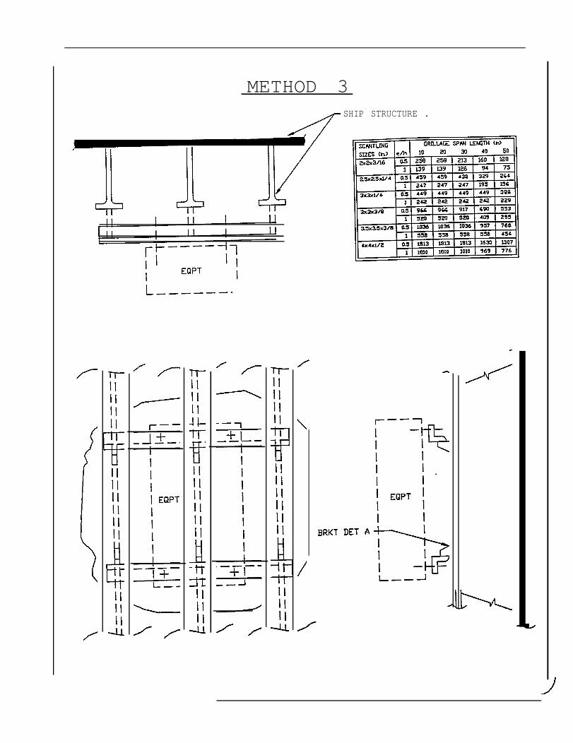
METHOD 3SHIP STRUCTURE .
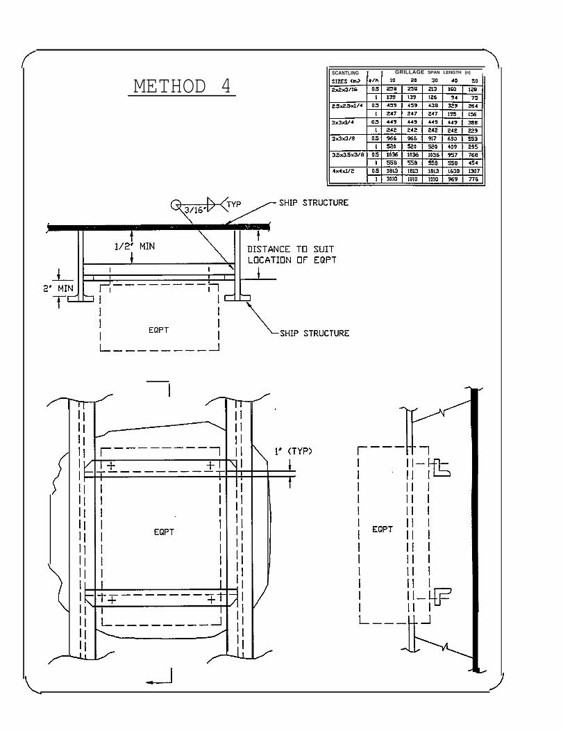
METHOD 4SCANTLING I I GRILLAGE SPAN LENGTH (n)
i
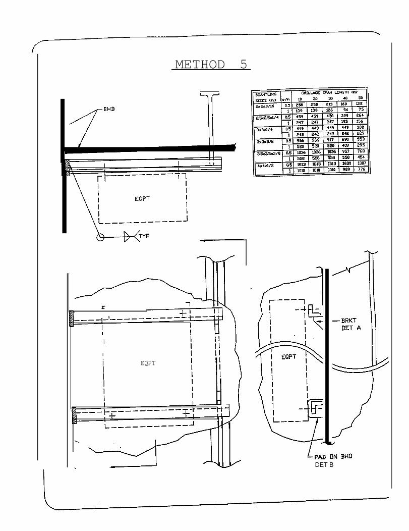
METHOD 5
r
I
I
iIII
EQPT
DET B
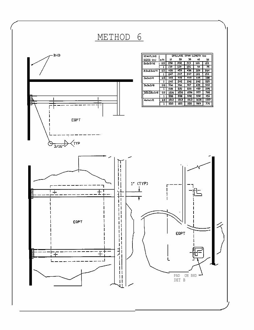
METHOD 6
PAD ON BHDDET B
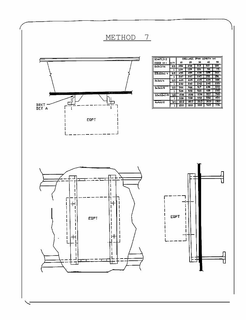
METHOD 7
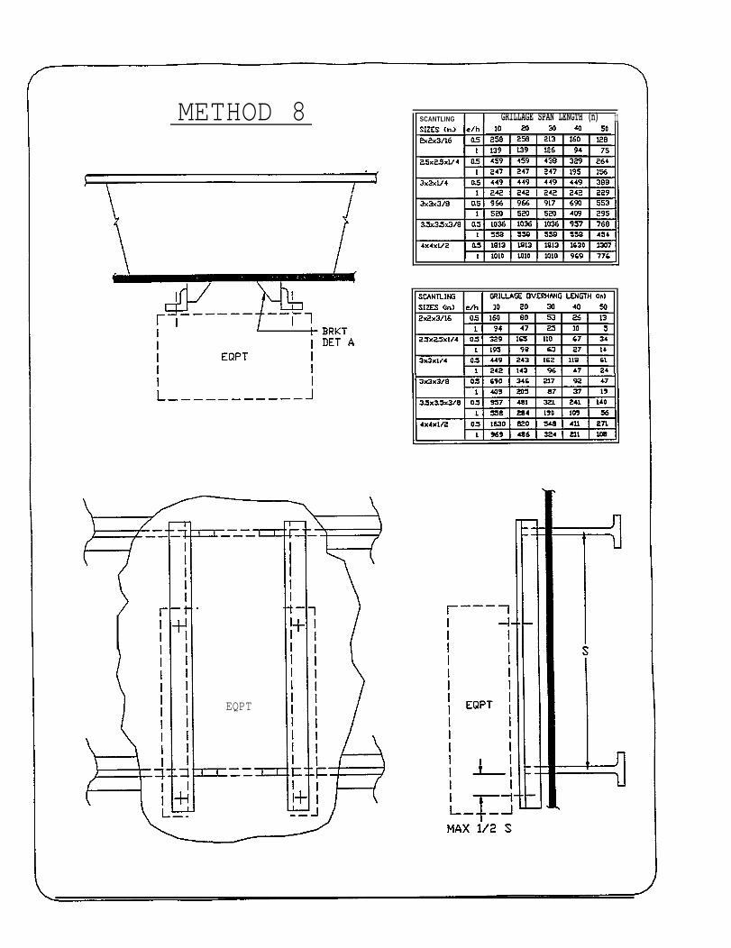
METHOD 8
EQPT
SCANTLING I I GRILLAGE SPAN LENGTH (n) 11
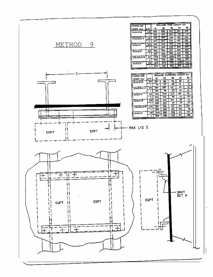
METHOD 9
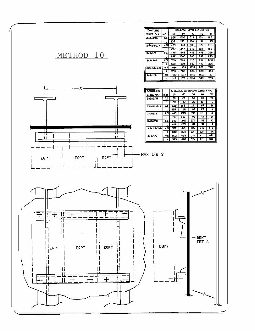
METHOD 10
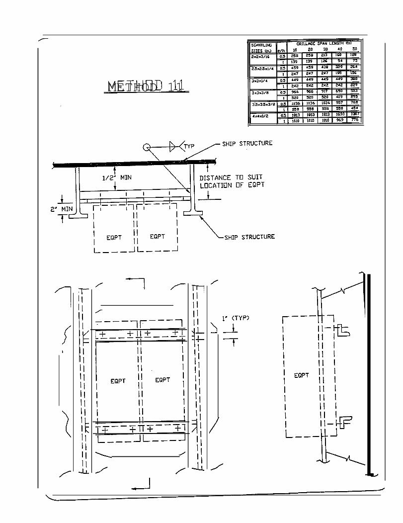
METHOD 11
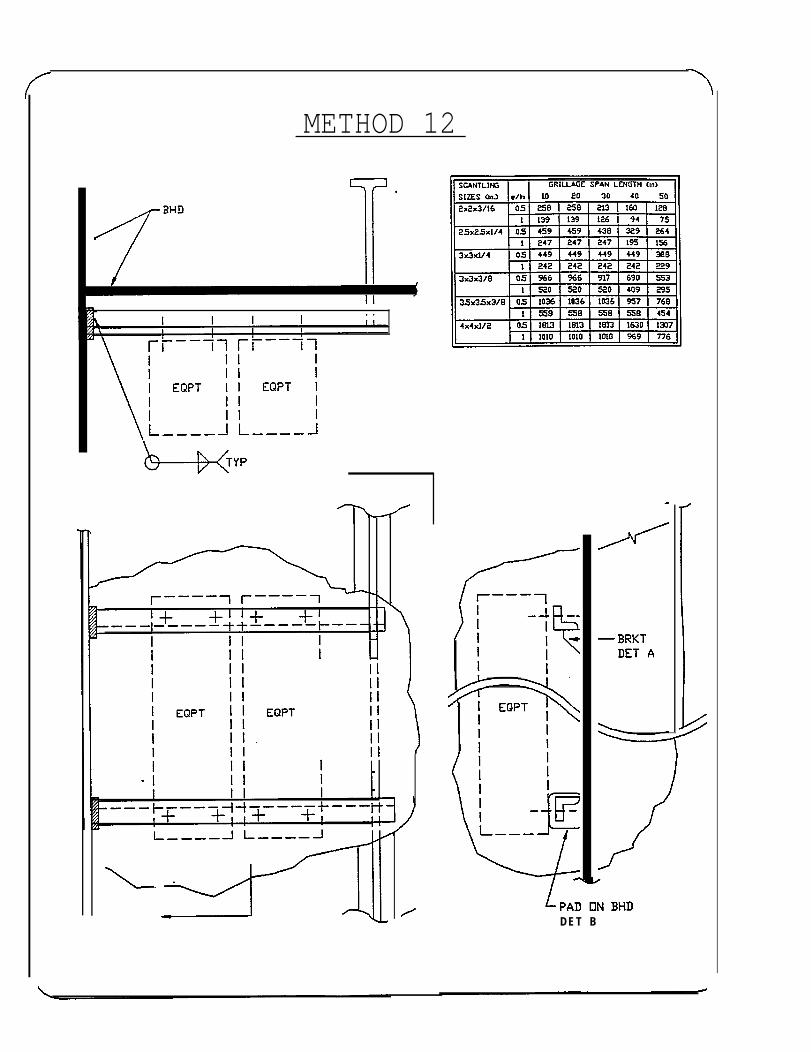
METHOD 12
DET B
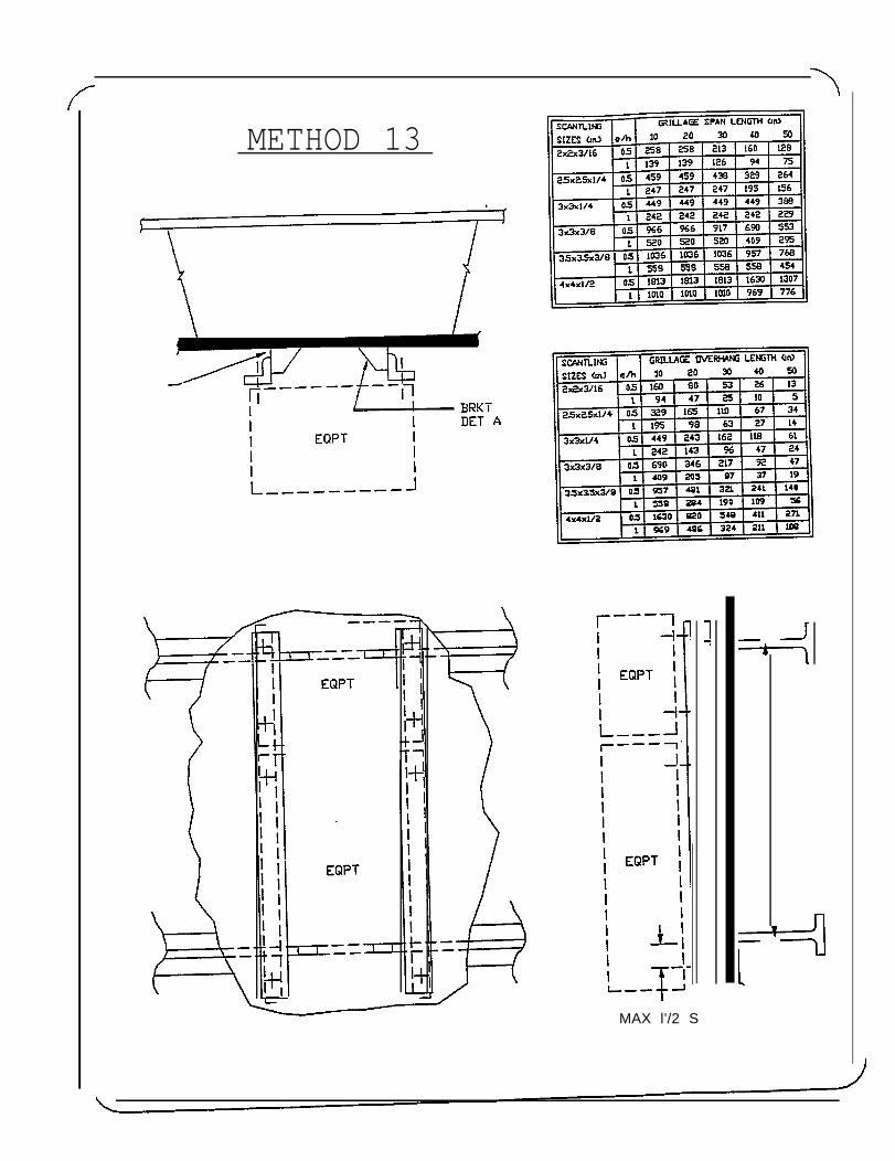
METHOD 13
MAX l’/2 S
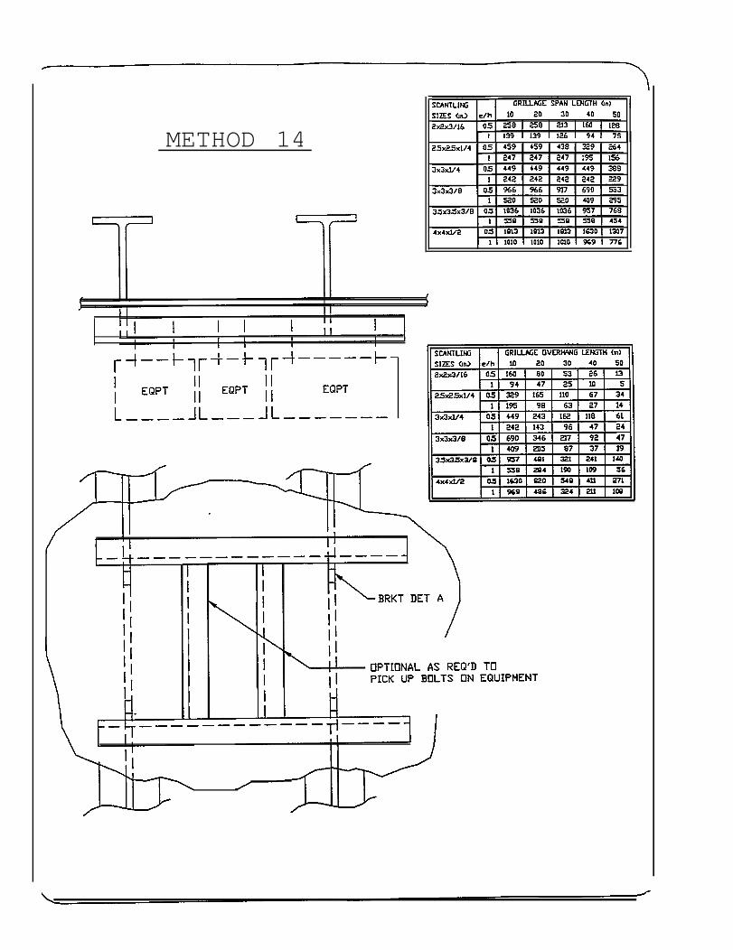
METHOD 14
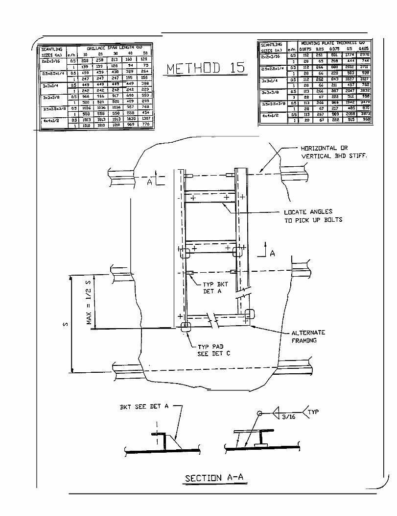
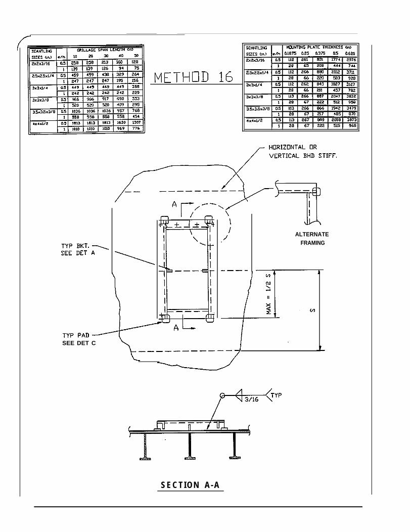
SEE DET C
ALTERNATEFRAMING
SECTION A-A
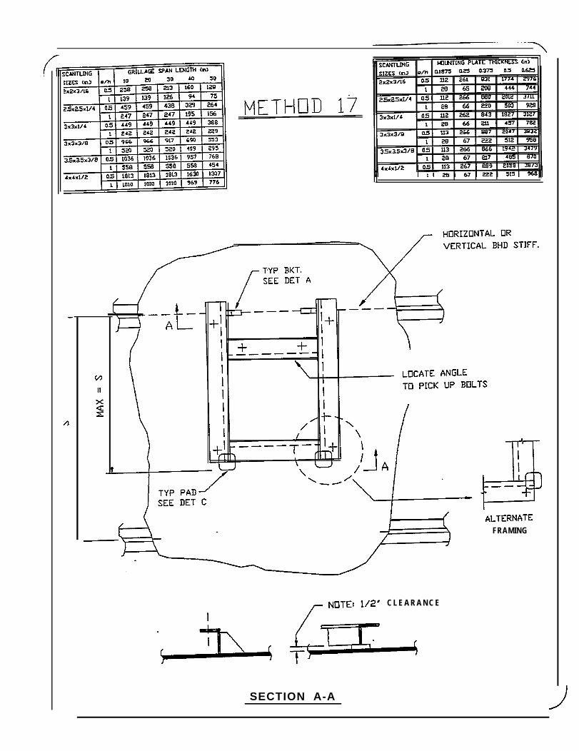
FRAMING
C L E A R A N C E
SECTION A-A
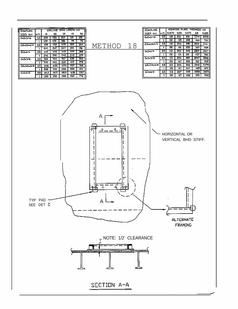
METHOD 18
HORIZONTAL ORVERTICAL BHD STIFF.
TYPSEE
PADDET
r NOTE: 1/2’ CLEARANCE
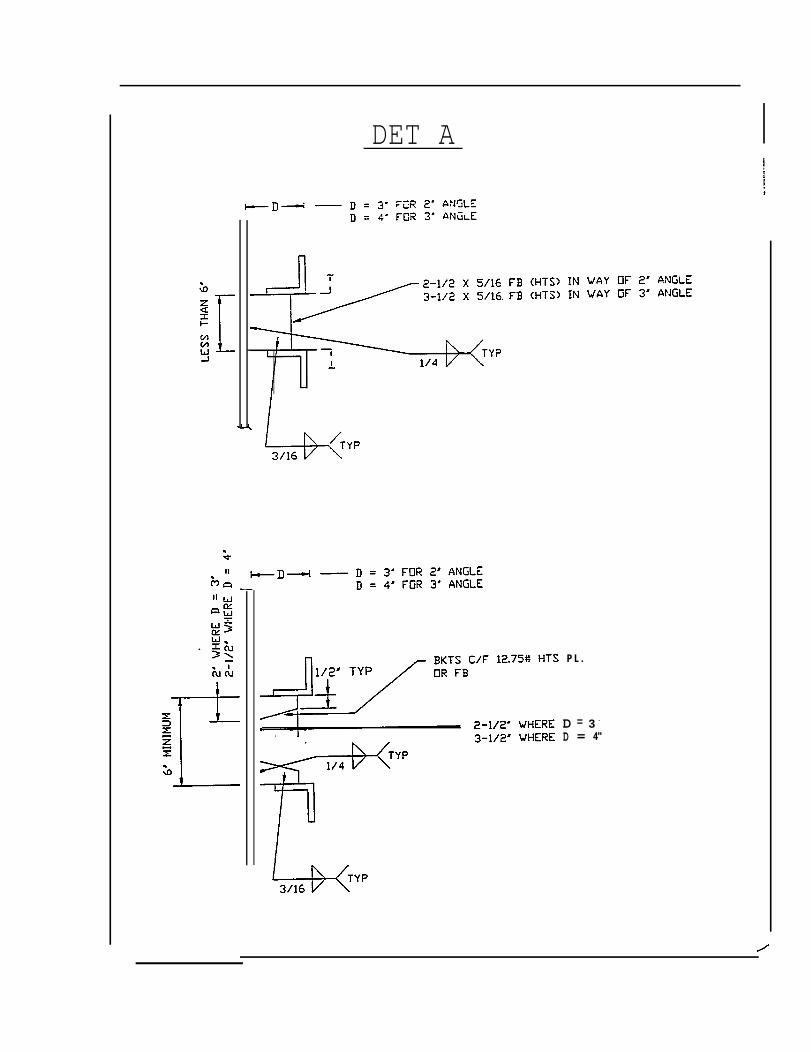
DET A
P L .
D 3 -=D = 4"
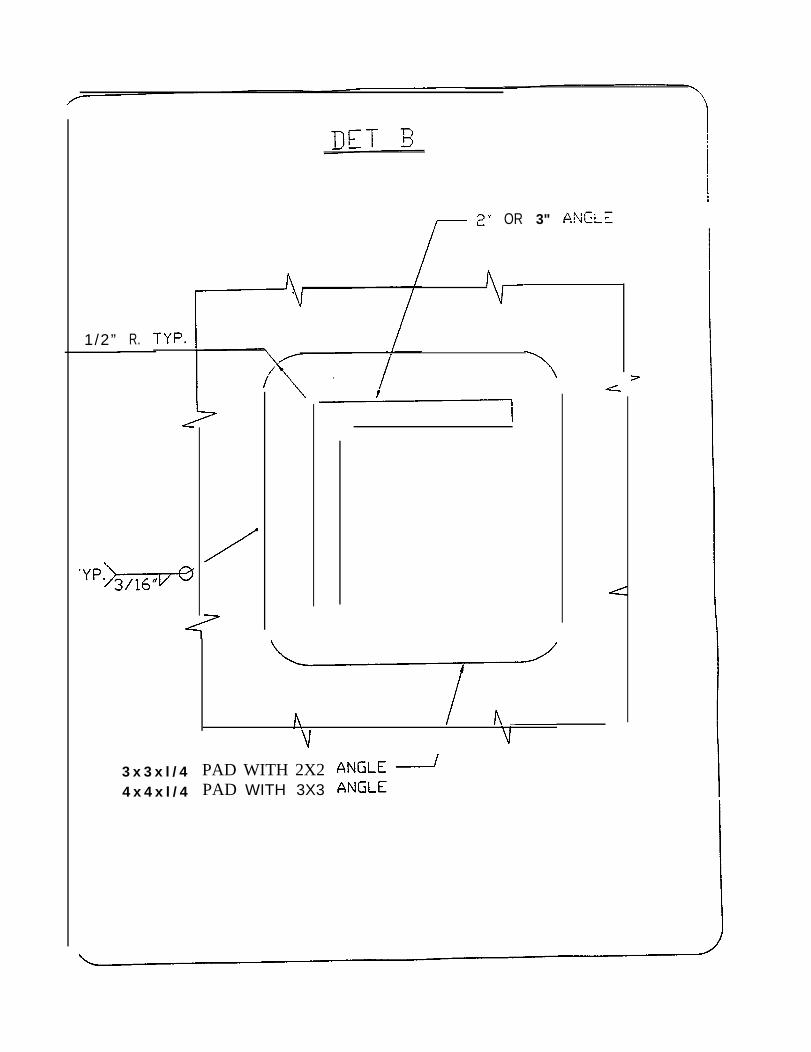
1/2” R.
OR 3"
3 x 3 x l / 44 x 4 x l / 4
PAD WITH 2X2PAD WITH 3X3
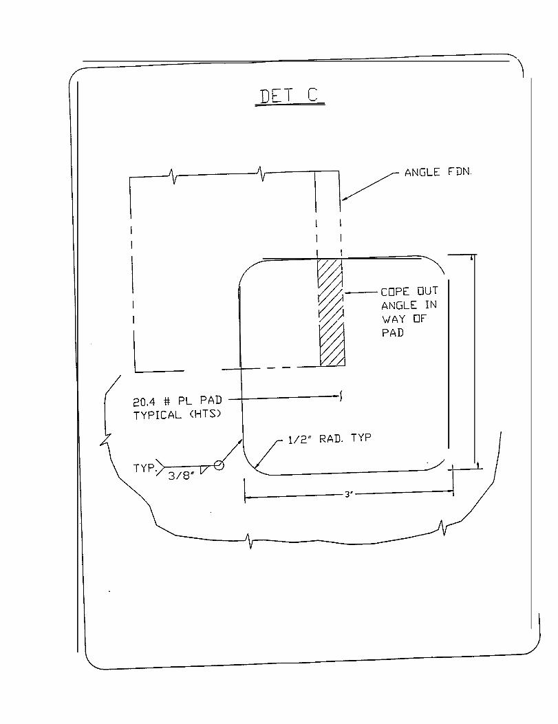
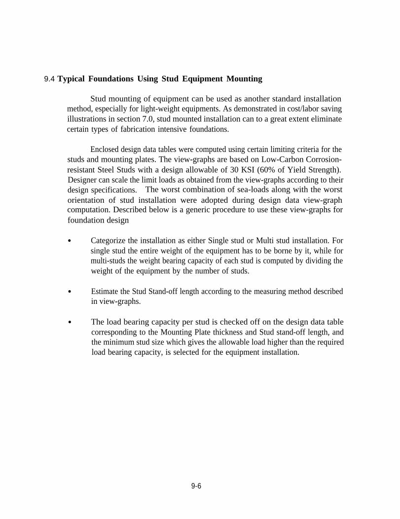
9.4 Typical Foundations Using Stud Equipment Mounting
Stud mounting of equipment can be used as another standard installationmethod, especially for light-weight equipments. As demonstrated in cost/labor savingillustrations in section 7.0, stud mounted installation can to a great extent eliminatecertain types of fabrication intensive foundations.
Enclosed design data tables were computed using certain limiting criteria for thestuds and mounting plates. The view-graphs are based on Low-Carbon Corrosion-resistant Steel Studs with a design allowable of 30 KSI (60% of Yield Strength).Designer can scale the limit loads as obtained from the view-graphs according to theirdesign specifications. The worst combination of sea-loads along with the worstorientation of stud installation were adopted during design data view-graphcomputation. Described below is a generic procedure to use these view-graphs forfoundation design
● Categorize the installation as either Single stud or Multi stud installation. Forsingle stud the entire weight of the equipment has to be borne by it, while formulti-studs the weight bearing capacity of each stud is computed by dividing theweight of the equipment by the number of studs.
● Estimate the Stud Stand-off length according to the measuring method describedin view-graphs.
● The load bearing capacity per stud is checked off on the design data tablecorresponding to the Mounting Plate thickness and Stud stand-off length, andthe minimum stud size which gives the allowable load higher than the requiredload bearing capacity, is selected for the equipment installation.
9-6
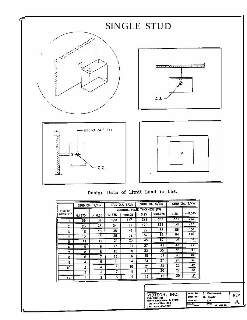
SINGLE STUD
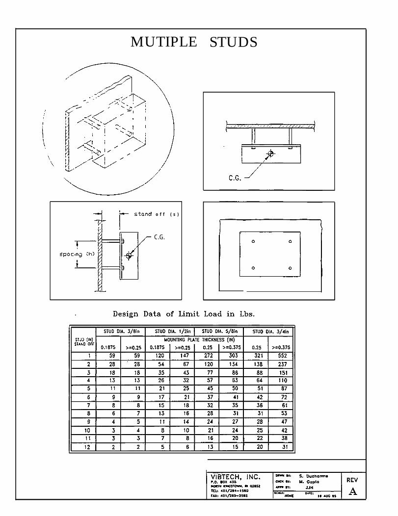
MUTIPLE
o f f ( s )
C.G.
STUDS
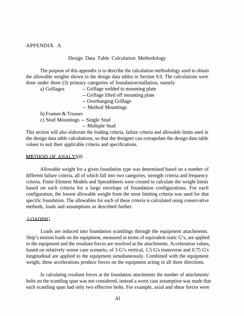
APPENDIX A
Design Data Table Calculation Methodology
The purpose of this appendix is to describe the calculation methodology used to obtainthe allowable weights shown in the design data tables in Section 9.0. The calculations weredone under three (3) primary categories of foundation/stallation, namely
a) Grillages -- Grillage welded to mounting plate-- Grillage lifted off mounting plate-- Overhanging Grillage-- Method Mountings
b) Frames & Trussesc) Stud Mountings -- Single Stud
-- Multiple StudThis section will also elaborate the loading criteria, failure criteria and allowable limits used inthe design data table calculations, so that the designer can extrapolate the design data tablevalues to suit their applicable criteria and specifications.
THOD OF ANALYSIS
Allowable weight for a given foundation type was determined based on a number ofdifferent failure criteria, all of which fall into two categories, strength criteria and frequencycriteria. Finite Element Models and Spreadsheets were created to calculate the weight limitsbased on each criteria for a large envelope of foundation configurations. For eachconfiguration, the lowest allowable weight from the most limiting criteria was used for thatspecific foundation. The allowables for each of these criteria is calculated using conservativemethods, loads and assumptions as described further.
.LOADING
Loads are induced into foundation scantlings through the equipment attachments.Ship’s motion loads on the equipment, measured in terms of equivalent static G’s, are appliedto the equipment and the resultant forces are resolved at the attachments. Acceleration values,based on relatively worse case scenario, of 3 G’s vertical, 1.5 G's transverse and 0.75 G'slongitudinal are applied to the equipment simultaneously. Combined with the equipmentweight, these accelerations produce forces on the equipment acting in all three directions.
In calculating resultant forces at the foundation attachments the number of attachments/bolts on the scantling span was not considered, instead a worst case assumption was made thateach scantling span had only two effective bolts. For example, axial and shear forces were
Al
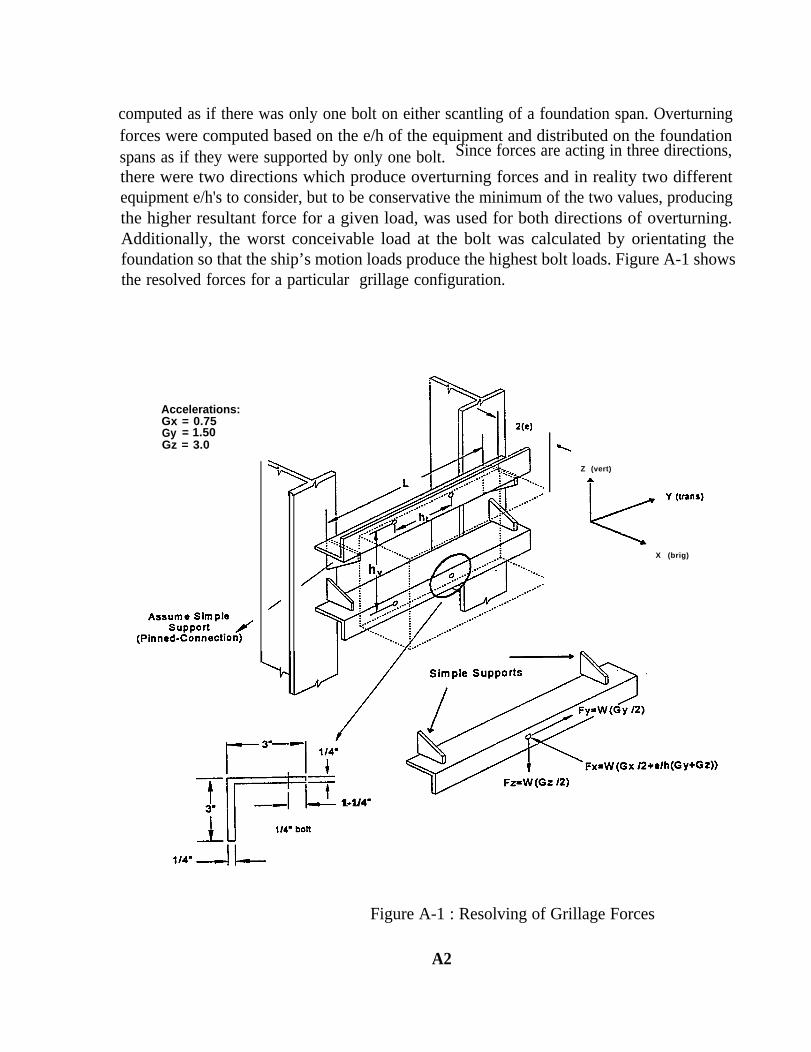
computed as if there was only one bolt on either scantling of a foundation span. Overturningforces were computed based on the e/h of the equipment and distributed on the foundationspans as if they were supported by only one bolt. Since forces are acting in three directions,
there were two directions which produce overturning forces and in reality two differentequipment e/h's to consider, but to be conservative the minimum of the two values, producingthe higher resultant force for a given load, was used for both directions of overturning.Additionally, the worst conceivable load at the bolt was calculated by orientating thefoundation so that the ship’s motion loads produce the highest bolt loads. Figure A-1 showsthe resolved forces for a particular grillage configuration.
Accelerations:Gx = 0.75Gy = 1.50Gz = 3.0
Z (vert)
X (brig)
1-1/4 =
Figure A-1 : Resolving of Grillage Forces
A2
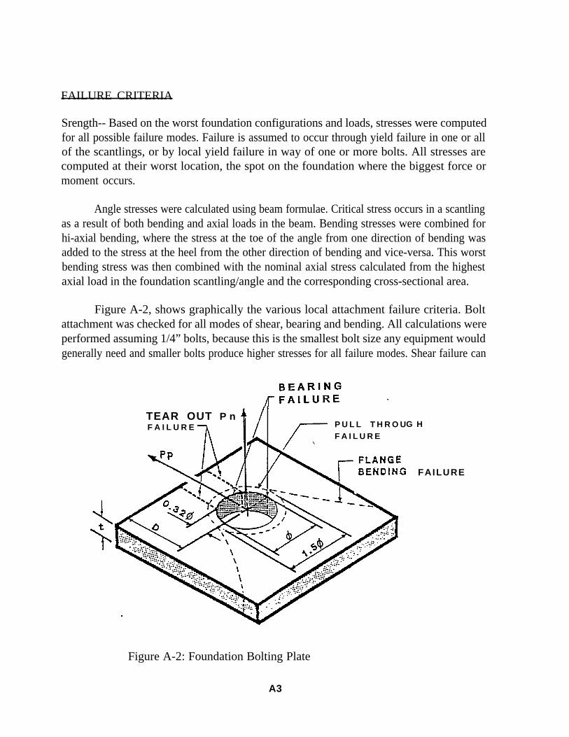
FAILURE CRITERIA
Srength-- Based on the worst foundation configurations and loads, stresses were computedfor all possible failure modes. Failure is assumed to occur through yield failure in one or allof the scantlings, or by local yield failure in way of one or more bolts. All stresses arecomputed at their worst location, the spot on the foundation where the biggest force ormoment occurs.
Angle stresses were calculated using beam formulae. Critical stress occurs in a scantlingas a result of both bending and axial loads in the beam. Bending stresses were combined forhi-axial bending, where the stress at the toe of the angle from one direction of bending wasadded to the stress at the heel from the other direction of bending and vice-versa. This worstbending stress was then combined with the nominal axial stress calculated from the highestaxial load in the foundation scantling/angle and the corresponding cross-sectional area.
Figure A-2, shows graphically the various local attachment failure criteria. Boltattachment was checked for all modes of shear, bearing and bending. All calculations wereperformed assuming 1/4” bolts, because this is the smallest bolt size any equipment wouldgenerally need and smaller bolts produce higher stresses for all failure modes. Shear failure can
TEAR OUT P nF A I L U R E P U L L T H R O U
F A I L U R EG H
FAILURE
Figure A-2: Foundation Bolting Plate
A3
where, Pn = Bolt load normal to the platePp = Bolt load parallel to the platet = plate thickness
= Bolt diameterD = Edge distance
either occur perpendicular to the angle flange due to axial bolt loads or parallel to the flangefrom shear loads in the bolt. Bearing stress is a nominal stress computed from the cross-sectional area of the bolt hole.
Flange bending is the result of the moment created between the centerline of a bolt andthe heel of the angle. The greater the bolt distance from the heel, the greater the flange bendingmoment. So to be conservative, the bolt was assumed to land at its furthest possible locationfrom the heel,i.e. approximately 35 to 40% of the flange width from the toe of the angle. Themoment produced is resisted partially at the bolt and partially at the angle heel depending onthe condition of fixity at those locations. The most conservative assumption for momentdistribution was assumed, which is when the equipment is always clamped to the flange at thebolt and the heel is partially free, putting 80% of the moment at the bolt and 20% at the heel.
Frequency -- For all foundations, it is important to insure that the lowest natural frequencyof vibration of the foundation is greater than the excitation frequency of the propeller. Thenatural frequency was checked for several modes of vibration, and the lowest natural frequencyof the foundation was compared to the allowable frequency. Springs included in the naturalfrequency calculation for a foundation are the bending of the scantling, in two directions, andthe flexibility of the flange. Torsional flexibility of the mounting scantlings were disregardedbecause of the assumption that the flange was clamped to the equipment. Three differentvibration modes were calculated for foundations, i.e. parallel to the mounting plane,perpendicular to the mounting plane, and due to over-turning motion of the equipment.
When a foundation does not fully land on rigid ship structure, it is necessary to checkthe natural frequency of the foundation coupled with the vibration of the mounting plate. Itis no longer necessary to include the angle as a spring in the vibration calculation, thus thesprings for this natural frequency calculation were the flange flexibility and the out-of-planebending of the mounting plate. The natural frequency was calculated for the perpendicular andover-turning modes of vibration.
A4
ALL.OWABLES
Stress -- The stress allowables were based on the assumptions that scantlings are of mild steeland studs are of high strength steel, having yield strength and tensile strength of 34 Ksi and 50Ksi, respectively.
Nominal Tensile Stress Allowable is 27.2 Ksi80% of Yield Strength
Shear Stress Allowable is 16.3 Ksi60% of Tensile Allowable
Bearing Stress Allowable is 21.8 Ksi80% of Tensile Allowable
Stress Allowable for Studs is 30.0 Ksi60% of Tensile Strength
Frequency -- Based on the propeller excitation frequency of 12 Hz, which is found mostly invessels of higher speeds, the allowable natural frequency for the foundations was kept 25%higher than the propeller excitation frequency. Thus, the allowable frequency used to obtainthe values in design data tables was 15 Hz.
FOUNDATION CONFIGURATION
Grillages -- Three different types of grillage configurations were considered for thecalculations, namely: Grillage welded to mounting plate Grillage lifted off mounting plate;Overhanging Grillage. Method Mountings are extensions or combinations of these threeprimary configurations. The allowable weights in the design data tables were obtained usinga spreadsheet approach to check for the various failure criteria for 6 different angle sizes, for2 cases of 4 ratios. Figure A-3 shows the Grillage Off-deck and Overhanging Grillageconfigurations.
Frames/Trusses -- Various configurations of Frames and Trusses were analyzed using finiteelement models (FEM) for 5 different angle sizes, for 2 cases of e/h ratios. The FEMs were runfor the worst combination of G loadings, and effect of overturning of equipment was alsoincluded. All the models were of 4 equal size legs and the mounting attachments(bolt locations)were assumed to be at the four comers of the mounting plane. The results of FEMs were usedto obtain the allowable weight capacity for the legs of the frames and trusses. Grillagespreadsheet approach was used to obtain the allowable weights for mounting scantlings.
A5
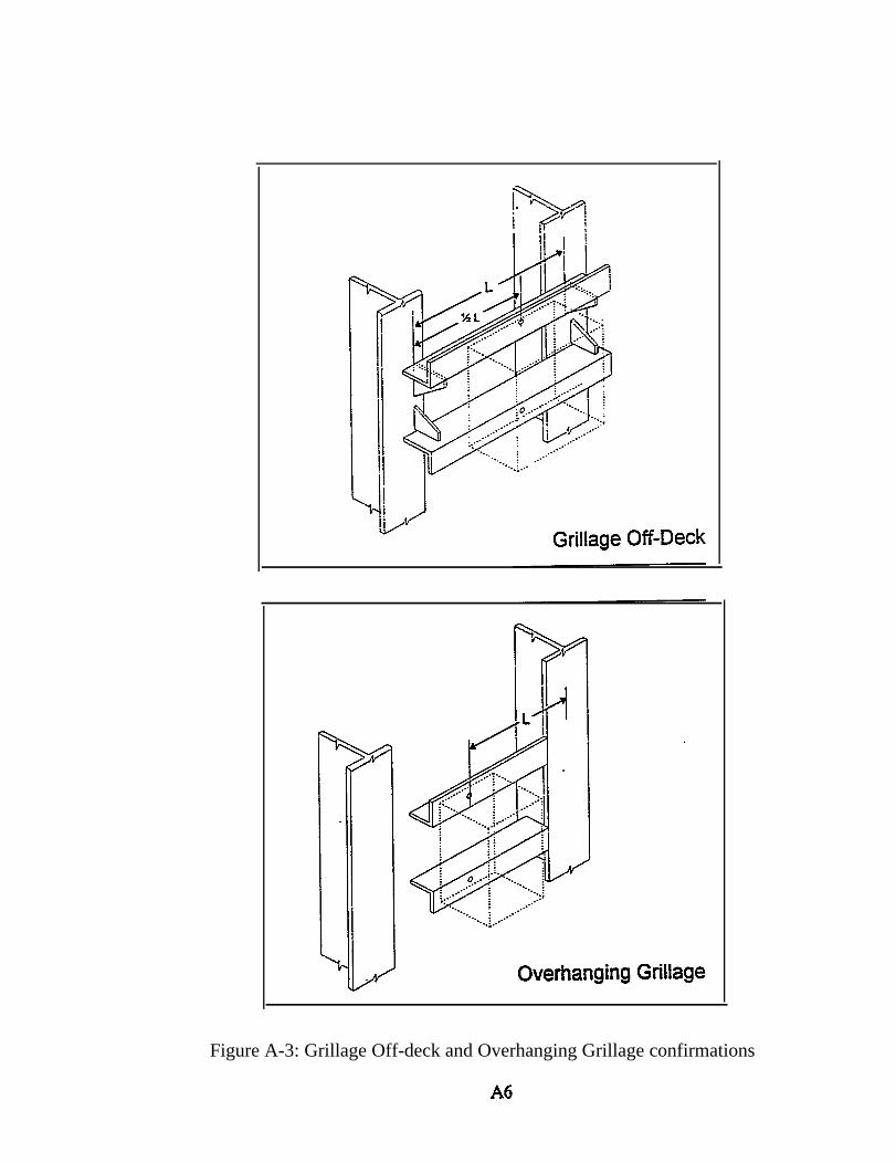
Figure A-3: Grillage Off-deck and Overhanging Grillage confirmations
Studs -- Studs of various lengths for four sizes, 3/8”, 1/2”, 5/8” and 3/4”, were analyzed usinga spreadsheet approach, to obtain the allowable weight capacities. The worst combination ofG loading on two configurations were analyzed, namely: single stud, and multiple stud (4studs). In case of single stud configuration, the varying stand off length was considered fromthe base of the stud to the C.G. of the equipment, thus taking equipment overturning intoconsideration. Whereas, for the multiple stud configuration the varying stand off length wasthe actual stud length, and the equipment overturning was assumed to be restrained.
Both vibration and strength limiting criteria were checked. Under vibration, frequencydue to out-of-plane mounting plate bending, and frequency due to stud and stud/plateconnection bending were checked for. Under strength limitation, studs by themselves werechecked for axial plus bending stresses. Further, the stud/plate connection was analyzed usingRoark’s equation (“Roark’s Formula for Stress and Strain”, Warren C. Young, 6th edition, pg.435, 1989), using plate thicknesses of 3/16”, 1/4” and 3/8”, because beyond these sizes thestud/plate connection was not the limiting criteria.
A7

APPENDIX B
Recommendations(Based on this project anditems 8 and 9)
Based on the developmentshould be performed:
foundations for double hull combatant papers -- Bibliography
work performed in this one year project, the following tasks
Expand the data base of equipment and foundations for existing classes of commercial ships and naval combatants.
Develop standard configurations based on the 27 representative foundationtypes for use on commercial ships and naval combatants.
Appraise the foundation data base to determine which foundations occurmost frequently so that producibility improvements can be implemented on asmany foundations as possible.
Complete additional investigations to better quantify the magnitudes andrelationships between slamming, whipping and vertical accelerations.
Develop a more comprehensive definition of foundation loading.
Investigate the machinery space structural system for combined loading toensure machinery performance.
Investigate the effects of hull flexibility on loads induced in foundations andmachinery system performance.
Develop standard foundation designs based on parametrically developedconfigurations.
Produce engineering validation of the standard foundation types byexpanding on the parametric analysis. This would entail extending theapproach used in this study to include a wider range of foundation types,scantlings, geometry’s and other important variables.
B1
●
●
●
●
●
●
●
●
●
Investigate shock induced distortions on foundation attachments to soft platein way of alignment sensitive equipment installations by FEA andappropriate shock testing.
Study the effects of heavier scantlings, placing an emphasis on the fatigueeffects.
Determine the impact of various steel strengths on the parametric foundationprocess.
The hot-spot stress range method should be applicable to a broad range ofdetails in conventional as well as double hulls. To evaluate this applicability,the full scale test data base should be broadened by testing a greater variety ofdetails. For example, the following should be evaluated through furthertesting 1) the effect of plate thickness, 2) the advantage of pad details, and 3)the range of eccentricities between one and six thickness’ where the transitionfrom weld root cracking to weld toe cracking occurs.
The effect of multi-axial loading should be further evaluated throughadditional full-scale testing, including: 1) loads in two or more axes that arealmost equal in magnitude, and 2) loads that are out-of-phase or at differentfrequencies.
Investigate the validity of the root-mean-cube effective stress range conceptthrough long life variable-amplitude loading, particularly in light of recentevidence that Miner’s rule can be unconservative for loading with widebandfrequency content like seaway loading.
Investigate the apparent crack arrest that often occurs in bending loading and(for very large eccentricity) in fully reversed axial loading.
Perform tests on mock-ups of attachments in way of light structure, decks,and bulkheads.
The modeling of configurations with bending loads should be refined, withspecial attention paid to accurate modeling to actual as well as nominaldimensions. If additional effort is needed in order to obtain good correlation,the use of a non-linear finite element analysis should be supported by FEA toprovide a basis for evaluating alternative configurations.
B2
● Clarification and revise traditional specifications with respect to the eccentricattachment detail.
● Develop quantitative requirements to clarify, enhance or replace thequalitative requirements for NAVSEA 0908-LP-OOO-3010 and specificationssections 072,073 and 180 as they apply to the advanced double hull structuresand conventional combatant structures.
● Design and producibility guidelines and requirements should be developedand mandated by the specifications to achieve cost and weight savings.
B3
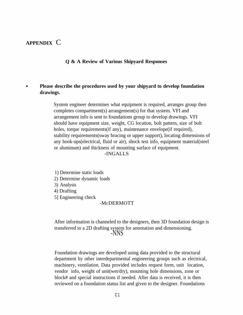
APPENDIX C
Q & A Review of Various Shipyard Responses
● Please describe the procedures used by your shipyard to develop foundationdrawings.
System engineer determines what equipment is required, arranges group thencompletes compartment(s) arrangement(s) for that system. VFI andarrangement info is sent to foundations group to develop drawings. VFIshould have equipment size, weight, CG location, bolt pattern, size of boltholes, torque requirements(if any), maintenance envelope(if required),stability requirements(sway bracing or upper support), locating dimensions ofany hook-ups(electrical, fluid or air), shock test info, equipment material(steelor aluminum) and thickness of mounting surface of equipment.
-INGALLS
1) Determine static loads2) Determine dynamic loads3) Analysis4) Drafting5] Engineering check
-McDERMOTT
After information is channeled to the designers, then 3D foundation design istransferred to a 2D drafting system for annotation and dimensioning.
-NNS
Foundation drawings are developed using data provided to the structuraldepartment by other interdepartmental engineering groups such as electrical,machinery, ventilation. Data provided includes request form, unit location,vendor info, weight of unit(wet/dry), mounting hole dimensions, zone orblock# and special instructions if needed. After data is received, it is thenreviewed on a foundation status list and given to the designer. Foundations
C1
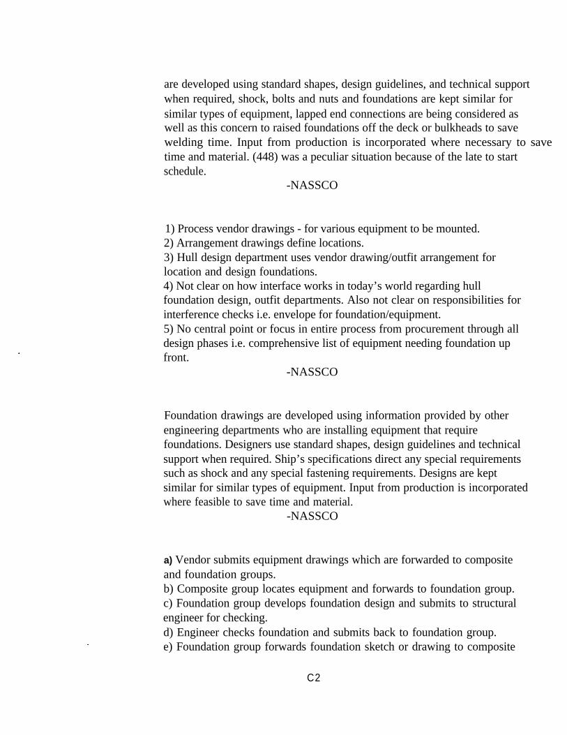
are developed using standard shapes, design guidelines, and technical supportwhen required, shock, bolts and nuts and foundations are kept similar forsimilar types of equipment, lapped end connections are being considered aswell as this concern to raised foundations off the deck or bulkheads to savewelding time. Input from production is incorporated where necessary to save time and material. (448) was a peculiar situation because of the late to startschedule.
-NASSCO
1) Process vendor drawings - for various equipment to be mounted.2) Arrangement drawings define locations.3) Hull design department uses vendor drawing/outfit arrangement forlocation and design foundations.4) Not clear on how interface works in today’s world regarding hullfoundation design, outfit departments. Also not clear on responsibilities forinterference checks i.e. envelope for foundation/equipment.5) No central point or focus in entire process from procurement through alldesign phases i.e. comprehensive list of equipment needing foundation upfront.
-NASSCO
Foundation drawings are developed using information provided by otherengineering departments who are installing equipment that requirefoundations. Designers use standard shapes, design guidelines and technicalsupport when required. Ship’s specifications direct any special requirementssuch as shock and any special fastening requirements. Designs are keptsimilar for similar types of equipment. Input from production is incorporatedwhere feasible to save time and material.
-NASSCO
a) Vendor submits equipment drawings which are forwarded to compositeand foundation groups.b) Composite group locates equipment and forwards to foundation group.c) Foundation group develops foundation design and submits to structuralengineer for checking.d) Engineer checks foundation and submits back to foundation group.e) Foundation group forwards foundation sketch or drawing to composite
C2
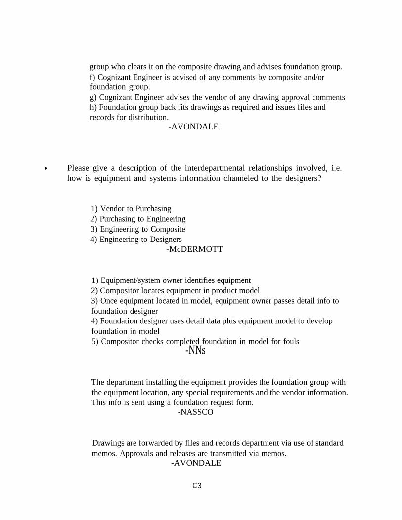
group who clears it on the composite drawing and advises foundation group.f) Cognizant Engineer is advised of any comments by composite and/orfoundation group.g) Cognizant Engineer advises the vendor of any drawing approval commentsh) Foundation group back fits drawings as required and issues files andrecords for distribution.
-AVONDALE
● Please give a description of the interdepartmental relationships involved, i.e.how is equipment and systems information channeled to the designers?
1) Vendor to Purchasing2) Purchasing to Engineering3) Engineering to Composite4) Engineering to Designers
-McDERMOTT
1) Equipment/system owner identifies equipment2) Compositor locates equipment in product model3) Once equipment located in model, equipment owner passes detail info tofoundation designer4) Foundation designer uses detail data plus equipment model to developfoundation in model5) Compositor checks completed foundation in model for fouls
-NNs
The department installing the equipment provides the foundation group withthe equipment location, any special requirements and the vendor information.This info is sent using a foundation request form.
-NASSCO
Drawings are forwarded by files and records department via use of standardmemos. Approvals and releases are transmitted via memos.
-AVONDALE
C3
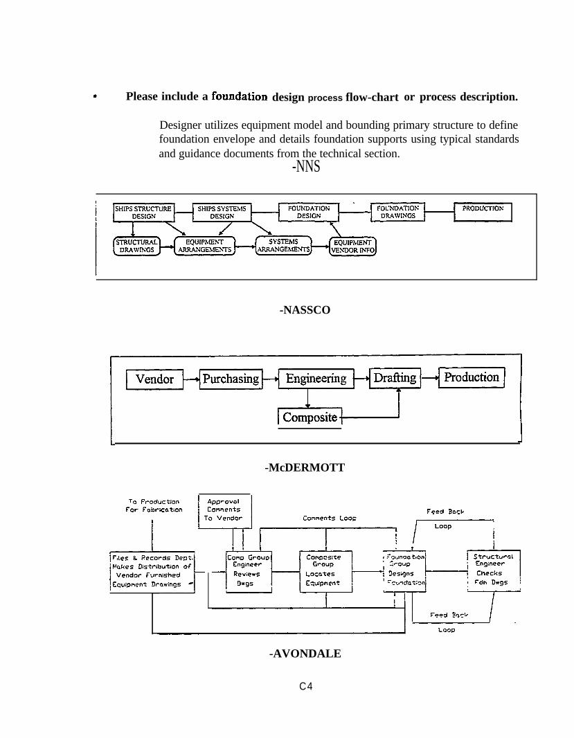
Please include a design process flow-chart or process description.
Designer utilizes equipment model and bounding primary structure to definefoundation envelope and details foundation supports using typical standardsand guidance documents from the technical section.
-NNS
-NASSCO
-McDERMOTT
-AVONDALE
C4
● Do your designers use a foundation design manual that includes graphs andtables to speed up the design process, or guidelines which illustrate the needsof production?
An Ingalls Designers’ Handbook-INGALLS
No-McDermott
Structural Details, Welding Design Details, Specifications and Design Rules-NNS
Yes, Standards presently working-NASSCO
A manual is used and is presently being revised to include more up to datereference material
-NASSCO
AII has used some standard design info in the past on our LSD contract anddoes use a production (fabrication) schedule to plan and sequence work tomeet production needs
-AVONDALE
● What are your pet peeves about foundation design and construction?
Lack of standards.-McDERMOTT
Detail design data for equipment is late and changes as different vendors areselected. This usually places the foundation designer in a continuous redesignloop.
-NNS
C5
Incomplete work packages - missing information required to design and buildthe foundation.
-NASSCO
Lack of standards. Excessive reinforcements. Welding details are anafterthought.
-NASSCO
Our main problem is getting the required information on time to meet ourschedule. Much too often, the vendor furnished information is missing.
-NASSCO
Lack of timely vendor information.-AVONDALE
● What are the most frequently encountered obstacles in your foundationdesign program (engineering)?
Time doesn’t permit economizing of foundations.
Lack of standardmanner.
-INGALLS
for dynamic loads. Lack of vendor data in a timely
-McDERMOTT
Lack of timely vendor information. Baseline design is lacking sufficient detail.Spaces end up being too crowded; which leads to poor arrangement whichcompromise foundation design, leading to costly designs.
-NASSCO
C6
● What are the most frequently encountered obstacles in your foundationdesign program (design)?
Inadequate VFI. Delayed receipt of VFI holds up the entire foundationdesign process.
-INGALLS
Incomplete equipment information. Limited space for designs.-McDERMOTT
Relocation of equipment after design is completed.-NASSCO
Non-standard designs.-AVONDALE
● What are the most frequently encountered obstacles in your foundationdesign program (drafting)?
Short time in drafting of foundation drawings due to late info or VFI that ischanged while designing foundation drawing.
-INGALLS
Lack of qualified designers.-McDERMOTT
. Each foundation is drawn separately, even if some foundations are similar.-AVONDALE
C7
● What are the most frequently encountered obstacles in your foundationdesign program planning)?
Lack of up-front planning for staging.-McDERMOTT
Foundation and foundation backing structure are typically notadded/built/installed at the same time. Tolerances must be established toensure that all will fit together after installation.
-NNS
Late info from other groups.-NASSCO
Difficult to meet schedules due to late info from other groups.-NASSCO
Shop workloads are difficult to properly anticipate when drawings are issuedso close to fabrication start dates. Standardization and up front identificationof foundation type would help.
-AVONDALE
● What are the most frequently encountered obstacles in your foundationdesign program (construction)?
Poor weld access; too many piece parts have to add temporary structure (e.g.lift lugs) to handle foundation during construction. These could have beendesigned in. Backup is obviously excessive. Obvious mismatch betweenfoundation and equipment (e.g. 100# structural foundation with backup tohold a sheet metal magazine rack). Machining used when liners would beadequate.
-INGALLS
C8
Many non-standard small parts to fabricate, fit weld prepare. Foundationgeometry not formed by straight lines and right angles.Loose parts such as braces lost in transit from shop to structural unit.Headers difficult to fit, trimming must be carried out.Interference of foundation structure, i.e. legs, diagonals, braces, with adjacent piping systems.Interface of foundations with ships structure, too much fitting and trimming,light decks tending to warp.Minimum welding clearances.
-NASSCO
Back-up structure not put in panel line stages.-McDERMOTT
Adding backing structure to a painted area due to late foundations.-NNS
Need more “system” view so dimensions are compatible and interferences arereduced.
-NASSCO
The shops sometimes do not build the foundation in accordance with thedrawing. Crafts sometimes install the foundation in the incorrect location.
-AVONDALE
● What are the most common problem you are forced to deal withinfabricating hull foundations?
Existing back-up structure.-McDERMOTT
Tracking material - configuration changes.-NNS
C9
High mix of material. Insufficient bolting clearances. Mismatch withcomponents. Poor interface with associated duct or other equipment.
-NASSCO
Late release of engineering drawings to shops because drawings cannot beprepared because of late vendor info.
-AVONDALE
● Do you have any suggestions on how the common foundation fabricationproblems could be most easily solved?
Timely vendor info.-McDERMOTT
Produce design guidance manual-for standard material configuration.Improve interface between design groups, particularly ventilation design andfoundation design. Improve knowledge of production processes withinengineering - weak area concerning “Design for Manufacturing”.
-NASSCO
Earlier equipment /vendor selection.-AVONDALE
● Are there any fabrication methods used by your shipyard that you believe tobe especially efficient?
Farming out the manufacture of commercial ship foundations to outsidevendors.
-NNS
Sheet metal shop use of CNC plasma/punch machine for cutting foundationsout of plate. Vent penetration spools from thicknesses 1/8” to 1“ thick. Allventilation duct work.
-NASSCO
C10
APPENDIX D
Bibliography
1.
2.
3.
4.
5.
6.
7.
8.
9.
10.
11.
AASHTO, Standard Specifications for Highway Bridges, American Association ofState Highway Transportation Officials, 14th edition, 1989.
AISC, Manual for Steel Construction, LRFD 1st ed. or ASD 9th ed., The AmericanInstitute of Steel Construction, Chicago, IL, 1991.
American Bureau of Shipping, “Guide for the Fatigue Strength Assessment ofTankers”, 1992.
AWS, Structural Welding Code. AWS D1.1-92, 13th edition, American WeldingSociety, 1992.
Bea, R. G., “Marine Structural Integrity Programs”, SSC #365, 1992.
Barrington, R. L., and Vorus, W. S.,’’Dynamic Shock Analysis of ShipboardEquipment”, SNAME, Hampton Roads Section, December 7, 1966.
Hopkinson, J. and Gallagher, P., “Foundation Design for Ship Construction CostSavings”, Joint ASNE and SNAME meeting, Pascogoula, MS, April 1993.
Hopkinson, J., “Standardization of Foundations to Achieve Ship Construction CostSavings”, NSRP SP-6 Panel Meeting, Bath, ME., June 1993.
Hopkinson, J., et al’’Producibility: Foundation Integration with Double-Hull” -Final Report NO0167-02-K-O042 for DTRC, Carderock, MD, September, 1993.
Hopkinson, J., Dexter, R. J., McAfee, D., “Foundations for Advanced Double HullCombatants”, The Advanced (Unidirectional) Double-Hull Technical Symposium,Maritime Administration, Gaithersburg, MD., October 25-26, 1994.
Jennings, E., Grubbs, K., Zanis, C., and Raymond, L., “Inelastic Deformation ofPlate Panels”, SSC #364, 1991.
D1
12. Marshall, P. W., Design of Welded Tubular Connections, Elsevier, New York, NY,1992.
13. Munse, Wilbur, Tellalian, “Fatigue Characterization of Fabricated Ship Details for “Design”, Ship Structure Committee #318, 1983.
14. NAVSEA O9O8-LP-OOO-3O1O - Shock Design Criteria for Surface Ships, May 1976.
15. NAVSEA, “Fabrication Welding & Inspection& Casting Inspection & Repair forMachinery and Piping”, MIL-STD-278E(SH), Jan 26, 1970.
16. Petershagen, H., “Fatigue Problems in Ship Structures”, Presented at Advances inMarine Structures Conference, Paper #14, ARE, Dunfermline, Scotland. 20-23 May,1986.
17. Stambaugh, VanMater & Munse, “Fatigue Performance Under Multi-axial LoadingMarine Structures”, SSC #356, June 1989.
18. Stambaugh, K. A., Leeson, D.. H., Lawrence, F., Hou, C-Y., Banas, G., “Reductionof S-N Curves for Ship Structural Details”, SSC #369, 1994.
19. Stambaugh, K. A., Lawrence, F.,and Dimitriakis, S., “Improved Ship Hu1lStructural DetaiIs Relative to Fatigue”, SSC #379, 1995.
20. “Steel Plate & Shapes, Weldable Ordinary Strength& Higher Strength: HullStructure”, MIL-S-22698B (SH), Nov 2, 1982.
D2

Additional copies of this report can be obtained from theNational Shipbuilding Research and Documentation Center:
http://www.nsnet.com/docctr/
Documentation CenterThe University of MichiganTransportation Research InstituteMarine Systems Division2901 Baxter RoadAnn Arbor, MI 48109-2150
Phone: 734-763-2465Fax: 734-936-1081E-mail: [email protected]