Themln/ltrs-pdfs/NASA-97-tm206266.pdf · NASA/TM{97{206266 Hyp ersonic Pitc hing-Momen t Shift for...
24
Transcript of Themln/ltrs-pdfs/NASA-97-tm206266.pdf · NASA/TM{97{206266 Hyp ersonic Pitc hing-Momen t Shift for...
NASA/TM{97{206266
Hypersonic Pitching-Moment Shift forStardust Reentry Capsule Forebody
William A. Wood
Langley Research Center, Hampton, Virginia
October 1997

The NASA STI Program O�ce ... in Pro�le
Since its founding, NASA has been dedicatedto the advancement of aeronautics and spacescience. The NASA Scienti�c and TechnicalInformation (STI) Program O�ce plays a keypart in helping NASA maintain thisimportant role.
The NASA STI Program O�ce is operated byLangley Research Center, the lead center forNASA's scienti�c and technical information.The NASA STI Program O�ce providesaccess to the NASA STI Database, thelargest collection of aeronautical and spacescience STI in the world. The Program O�ceis also NASA's institutional mechanism fordisseminating the results of its research anddevelopment activities. These results arepublished by NASA in the NASA STI ReportSeries, which includes the following reporttypes:
� TECHNICAL PUBLICATION. Reports ofcompleted research or a major signi�cantphase of research that present the resultsof NASA programs and include extensivedata or theoretical analysis. Includescompilations of signi�cant scienti�c andtechnical data and information deemedto be of continuing reference value. NASAcounter-part of peer-reviewed formalprofessional papers, but having lessstringent limitations on manuscriptlength and extent of graphicpresentations.
� TECHNICAL MEMORANDUM.Scienti�c and technical �ndings that arepreliminary or of specialized interest,e.g., quick release reports, workingpapers, and bibliographies that containminimal annotation. Does not containextensive analysis.
� CONTRACTOR REPORT. Scienti�c andtechnical �ndings by NASA-sponsoredcontractors and grantees.
� CONFERENCE PUBLICATION.Collected papers from scienti�c andtechnical conferences, symposia,seminars, or other meetings sponsored orco-sponsored by NASA.
� SPECIAL PUBLICATION. Scienti�c,technical, or historical information fromNASA programs, projects, and missions,often concerned with subjects havingsubstantial public interest.
� TECHNICAL TRANSLATION. English-language translations of foreign scienti�cand technical material pertinent toNASA's mission.
Specialized services that help round out theSTI Program O�ce's diverse o�erings includecreating custom thesauri, building customizeddatabases, organizing and publishingresearch results. . . even providing videos.
For more information about the NASA STIProgram O�ce, see the following:
� Access the NASA STI Program HomePage at http://www.sti.nasa.gov
� E-mail your question via the Internet [email protected]
� Fax your question to the NASA AccessHelp Desk at (301) 621{0134
� Phone the NASA Access Help Desk at(301) 621{0390
� Write to:NASA Access Help DeskNASA Center for AeroSpace Information800 Elkridge Landing RoadLinthicum Heights, MD 21090{2934

NASA/TM{97{206266
Hypersonic Pitching-Moment Shift forStardust Reentry Capsule Forebody
William A. Wood
Langley Research Center, Hampton, Virginia
National Aeronautics andSpace Administration
Langley Research CenterHampton, Virginia 23681{2199
October 1997

Available from the following:
NASA Center for AeroSpace Information (CASI) National Technical Information Service (NTIS)
800 Elkridge Landing Road 5285 Port Royal Road
Linthicum Heights, MD 21090{2934 Spring�eld, VA 22161{2171
(301) 621{0390 (703) 487{4650
Abstract
Aerodynamic coe�cients are presented for perfect-gas and equilibrium-airsolutions of the Navier-Stokes equations about the Stardust reentry-capsule fore-body at Mach numbers of 4.6, 7, 8.5, and 10. A comparison with Newtonian- ow assumptions indicates a divergence of the aerodynamic coe�cients fromNewtonian- ow for Mach numbers less than 10. The static stability of the fore-body is reduced by a factor of 2.5 with decreasing freestream Mach numberbetween Mach 10 and 7.
Nomenclature
A Area, m2
C Force or moment coe�cientCP Pressure coe�cientc Reference length, me Unit vector, mh Altitude, kmi; j Computational indiciesM Mach numbern Unit normal vector, mP Pressure, PaS Reference area, m2
T Temperature, Kt Time during trajectory, st Tangent vector, mV Velocity, m/sx; y; z Cartesian body axes, m� Angle of attack, degrees Ratio of speci�c heats�; � Surface inclination angles, rad� Density, kg/m3
Subscripts:
A Axial forceE Surface elementN Normal forceM Pitching moment02 Post-shock stagnation value1 Freestream
Introduction
Stardust[1] is a comet sample-and-return mission slated for the end of thecentury. Trajectory calculations for Earth atmospheric reentry require a deter-mination of the capsule aerodynamics. Of primary interest for the axisymmetriccapsule are lift, drag, and pitching moment coe�cients.
1

Laminar, thin-layer Navier-Stokes solutions are obtained at four trajectory
points, Mach 4.6, 7, 8.5, and 10, for the Stardust forebody, assuming a base pres-
sure equal to freestream static pressure. Use of this base pressure assumption
at similar Mach-number conditions for the Commercial Experiment Transporter
(COMET) reentry capsule has been shown to produce errors of one percent or
less[2, 3]. A complete set of Stardust aerodynamics has been published by
Mitcheltree et al[4], including a subset of the present data.
Navier-Stokes solutions are compared with results using Newtonian- ow as-
sumptions, revealing a sudden shift from Newtonian-like ow at the highest
altitude/Mach number point to a non-Newtonian surface pressure distribution
at lower altitudes/Mach numbers. While the trend away from Newtonian- ow
as the Mach number decreases is expected, of note for this case is how abrupt
the departure is between Mach 7 and 10. Over this Mach number range, cov-
ering eight seconds of ight time, the forebody static stability decreases by a
factor of 2.5.
Con�guration
The physical con�guration of the Stardust reentry-capsule forebody is a
spherically-blunted 60 degree half-angle cone. The nose radius is 0.23 m, the
shoulder radius is 0.02 m, and the base radius is 0.41 m.
The axisymmetric computational grid contains 30 streamwise cells and 64
cells normal to the body, in a structured quadrilateral framework. Grid adaption
was performed to align with the bow shock and boundary layer.
For the three-dimensional cases, a singularity-free grid is employed with a
58 by 29 cell surface mesh and 48 cells normal to the body. Figure 1 displays
a side view of the surface mesh. Only the starboard side of the vehicle was
computed, with left-right symmetry assumed in the ow�eld. Adaption was
performed on this grid to align with the bow shock and boundary layer.
Computational Methods
Laminar, thin-layer Navier-Stokes calculations were performed using the
Langley Aerothermodynamic Upwind Relaxation Algorithm (LAURA)[5, 6].
LAURA is a second-order accurate �nite-volume approximate Riemann solver[7].
Previous applications to Earth reentry capsules include COMET[2, 3] and the
Aeroassist Flight Experiment[8]. Both perfect-gas and equilibrium-air[9] models
were employed.
Modi�ed-Newtonian solutions based on impact theory for hypersonic vehicles
were calculated using the code presented in the appendix. This code was written
speci�cally to be compatible with LAURA.
Cases
Four freestream conditions are considered, Mach 4.6, 7, 8.5, and 10, at 5 de-
grees angle of attack. Complete freestream descriptions are contained in Table 1.
2

-0.4 -0.2 0 0.2Z, m
-0.4
-0.3
-0.2
-0.1
0
0.1
0.2
0.3
0.4
X,m
V∞
α
Figure 1: Side view of singularity-free surface mesh for Stardust reentry capsule
forebody.
M1
h T1
�1
V1
t
10.3 44.4 255 2:04� 10�3 3290 82
8.5 43.2 252 2:41� 10�3 2720 86
7.1 42.1 250 2:82� 10�3 2270 90
4.6 39.6 244 4:09� 10�3 1470 100
Table 1: Freestream conditions.
The Mach 4.6 solution is for a perfect gas, while equilibrium air is used for the
Mach 7{10 results.
Three axisymmetric solutions were also obtained, at Mach 7 and 10, equi-
librium air, and Mach 7, perfect gas.
All Newtonian results are for perfect gas.
Results
Axial-force coe�cients are presented in Table 2 for all cases. The reference
area is 0.5189 m2. For CA, unmodi�ed-Newtonian results with a base-pressure
correction, as described in the appendix, are tabulated for comparison with the
LAURA solutions. Excellent, agreement is seen for axial force between the two
methods for Mach 7{10. At Mach 4.6, 5 degrees angle of attack, the Newtonian
axial force is 8.5 percent higher than the LAURA result, indicating a breakdown
3

M1
method � 4.6 7 7 (pg) 8.5 10
LAURA 0 | 1.506 1.454 | 1.515
Newtonian 0 | 1.51 | | 1.50
LAURA 5 1.41 1.477 | 1.496 1.498
Newtonian 5 1.53 1.50 | 1.50 1.49
Table 2: Axial-force coe�cients.
of the assumptions behind impact theory at those conditions.
Looking at the e�ect of gas model on the Mach-7, axisymmetric solution,
the perfect-gas CA is 3.4 percent lower than the equilibrium-air result.
Normal-force coe�cients calculated at 5 degrees angle of attack are plotted
in Figure 2 versus freestream Mach number. Included with the LAURA results
are modi�ed-Newtonian solutions. The modi�ed-Newtonian results are nearly
independent of Mach number at CN = 0:04. LAURA predicts the Newtonian
result at Mach 10, but shows nearly a 50 percent decrease in normal force
coe�cient by Mach 7, with a similar number at Mach 4.6 of CN = 0:021.
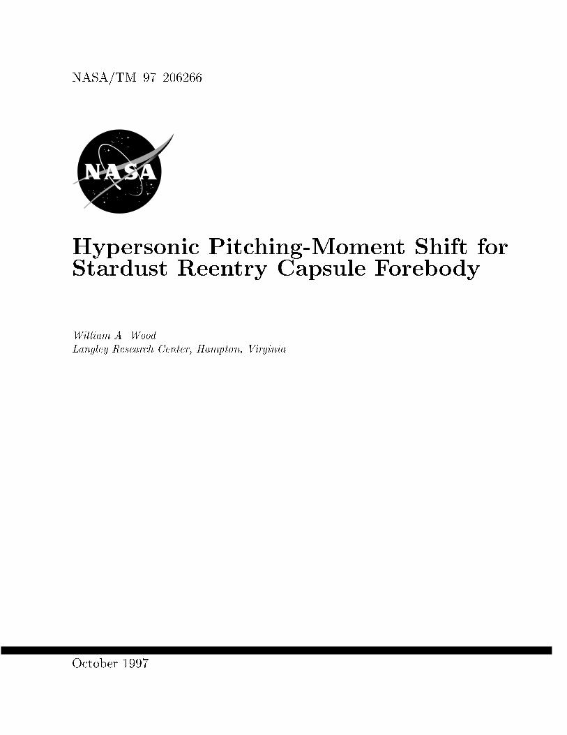
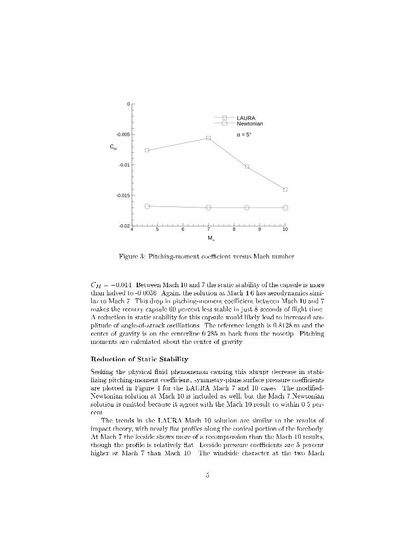
A similar shift in values occurs for the pitching-moment coe�cient, Fig-
ure 3. At Mach 10 the LAURA solution agrees with modi�ed-Newtonian, giving
4 5 6 7 8 9 100
0.01
0.02
0.03
0.04
0.05
M∞
CN
LAURANewtonian
α = 5°
Figure 2: Normal-force coe�cient versus Mach number.
4
4 5 6 7 8 9 10-0.02
-0.015
-0.01
-0.005
0
M∞
CM
LAURANewtonian
α = 5°
Figure 3: Pitching-moment coe�cient versus Mach number.
CM = �0:014. Between Mach 10 and 7 the static stability of the capsule is more
than halved to -0.0056. Again, the solution at Mach 4.6 has aerodynamics simi-
lar to Mach 7. This drop in pitching-moment coe�cient between Mach 10 and 7
makes the reentry capsule 60 percent less stable in just 8 seconds of ight time.
A reduction in static stability for this capsule would likely lead to increased am-
plitude of angle-of-attack oscillations. The reference length is 0.8128 m and the
center of gravity is on the centerline 0.285 m back from the nosetip. Pitching
moments are calculated about the center of gravity.
Reduction of Static Stability
Seeking the physical uid phenomenon causing this abrupt decrease in stabi-
lizing pitching-moment coe�cient, symmetry-plane surface pressure coe�cients
are plotted in Figure 4 for the LAURA Mach 7 and 10 cases. The modi�ed-
Newtonian solution at Mach 10 is included as well, but the Mach 7 Newtonian
solution is omitted because it agrees with the Mach 10 result to within 0.5 per-
cent.
The trends in the LAURA Mach 10 solution are similar to the results of
impact theory, with nearly at pro�les along the conical portion of the forebody.
At Mach 7 the leeside shows more of a recompression than the Mach 10 results,
though the pro�le is relatively at. Leeside pressure coe�cients are 5 percent
higher at Mach 7 than Mach 10. The windside character at the two Mach
5

-0.4 -0.2 0 0.2 0.40
0.2
0.4
0.6
0.8
1
1.2
1.4
1.6
1.8
2
X, m
CP
LAURA M∞ = 10LAURA M∞ = 7Newtonian M∞ = 10
Windside
Leeside
Figure 4: Symmetry-plane surface pressure coe�cients at 5 degrees angle of
attack.
numbers di�ers signi�cantly, with the pressure dropping o� signi�cantly toward
the shoulder at the lower Mach number. This change in character of the surface
pressure distribution between Mach 10 and 7, an increase in the leeside pressure
and a dropo� of the windside pressure toward the shoulder, is responsible for
the reduction in pitching-moment coe�cient at these hypersonic speeds.
Looking at surface pressure distributions, the Mach 7 and 10 LAURA surface-
pressure coe�cients are presented side-by-side in Figure 5. On the conical pro-
tion of the forebody the Mach 10 contours form predominantly radial lines,
consistent with impact theory. At Mach 7, however, the surface CP contours
are highly curved, more consistent with a locally subsonic distribution. The
patterns seen in Figure 5 suggest a change in the nature of the sonic bubble
between Mach 7 and 10.
Figure 6 displays such a change in the nature of the sonic bubble. Plotted
over a head-on view of the heatshield surface is the location of the sonic line, out-
side the boundary layer, for the Mach 7 and 10 LAURA solutions. At Mach 10
the sonic bubble contains the spherical nosepoint and the windward third of the
forebody cone. By Mach 7, though, the sonic bubble encompasses two-thirds of
the forebody, allowing signi�cant three-dimensional relieving e�ects for the fore-
body ow, resulting in the surface pressure distributions previously compared
in Figure 5.
6

-0.4 -0.2 0 0.2 0.4
-0.3
-0.2
-0.1
0
0.1
0.2
0.3
0.4
X, m
Y, mWindside
Leeside
M∞ = 7 M∞ = 10
CP contoursspaced by0.04
Figure 5: Surface CP contours for LAURA Mach 7 and 10 solutions, � = 5o.
-0.5 -0.25 0 0.25 0.5
-0.25
0
0.25
0.5
X, m
Y, mWindside
LeesideM∞ = 7 M∞ = 10
Figure 6: Sonic bubble locations for LAURA Mach 7 and 10 solutions, � = 5o.
7

Summary of Results
Aerodynamic coe�cients are calculated for the Stardust reentry-capsule fore-
body at Mach 4.6, 7, 8.5, and 10. Axial-force coe�cients agree well with
Newtonian- ow assumptions for Mach 7{10. Normal-force and pitching-moment
coe�cients agree with Newtonian at Mach 10, but reduce sharply in magnitude
with decreasing Mach number, dropping more than half their values by Mach 7.
The reduction in static stability by 60 percent is investigated and found to
correspond with a change in the inviscid sonic-bubble location. The sonic bubble
grows with increasing Mach number to encompass two-thirds of the forebody
by Mach 7, at 5 degrees angle of attack.
8

Appendix
A Modi�ed-Newtonian Surface Pressure
Calculator Compatible with LAURA[10]
Abstract
Modi�ed-Newtonian surface pressure coe�cients are calculated and inte-grated to obtain lift and drag coe�cients. Three-dimensional geometries de�nedas a structured surface mesh are assumed, with freestream pressure imposed onshadowed portions of the geometry. Inputs required are the surface mesh, owangle of attack, freestream Mach number, ratio of speci�c heats, and a nor-malizing length and area. Axial/normal and lift/drag force coe�cients and thepitching moment coe�cient are output. A plot �le is created of the surfacepressure coe�cient. Compatability with LAURA is emphasized and the sourcecode is presented in a User's Manual format to aid in customization.
Governing Equations
Modi�ed-Newtonian surface pressures (see Anderson[11] x3.2{3.5, or Bertin[12]x6.2{6.3), based on impact theory, are calculated according to,
CP
CP;max
= sin2 � = cos2 � (1)
where the pressure coe�cient is de�ned as,
CP =P � P11
2�1V 2
1
(2)
Straight-Newtonian is obtained in Eqn. 1 by setting CP;max = 2. � is theinclination angle of the surface to the freestream velocity vector, V1. � is theangle between V1 and the unit-normal to the surface, n. � and � are relatedas � = �
2� �.
Eqn. 1 is evaluated at a point using the relation,
cos� = �eV � n (3)
where eV is the unit vector along V1, so that V1 = V1eV .
Initializations
The surface is read as a structured mesh in i and j. x, y, and z are thenodal coordinates.
9
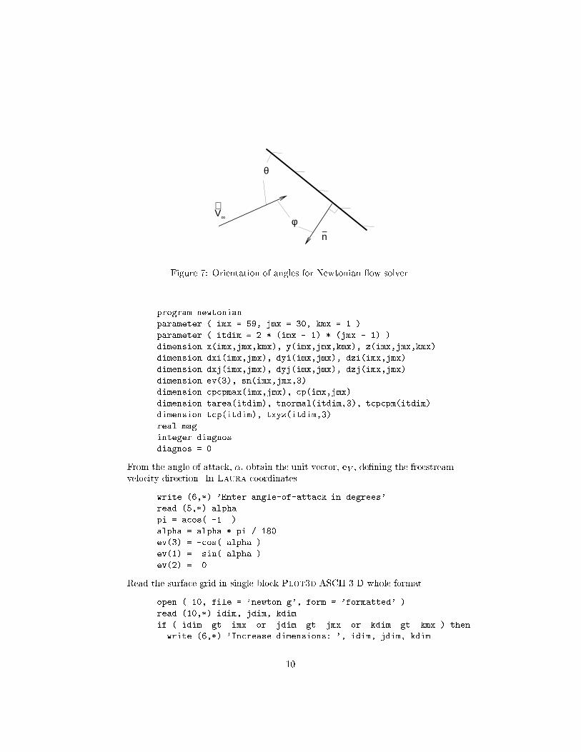
V∞
−n
θ
φ
Figure 7: Orientation of angles for Newtonian ow solver.
program newtonian
parameter ( imx = 59, jmx = 30, kmx = 1 )
parameter ( itdim = 2 * (imx - 1) * (jmx - 1) )
dimension x(imx,jmx,kmx), y(imx,jmx,kmx), z(imx,jmx,kmx)
dimension dxi(imx,jmx), dyi(imx,jmx), dzi(imx,jmx)
dimension dxj(imx,jmx), dyj(imx,jmx), dzj(imx,jmx)
dimension ev(3), sn(imx,jmx,3)
dimension cpcpmax(imx,jmx), cp(imx,jmx)
dimension tarea(itdim), tnormal(itdim,3), tcpcpm(itdim)
dimension tcp(itdim), txyz(itdim,3)
real mag
integer diagnos
diagnos = 0
From the angle-of-attack, �, obtain the unit vector, eV , de�ning the freestream
velocity direction. In Laura coordinates.
write (6,*) 'Enter angle-of-attack in degrees'
read (5,*) alpha
pi = acos( -1. )
alpha = alpha * pi / 180.
ev(3) = -cos( alpha )
ev(1) = sin( alpha )
ev(2) = 0.
Read the surface grid in single-block Plot3d ASCII 3-D whole format.
open ( 10, file = 'newton.g', form = 'formatted' )
read (10,*) idim, jdim, kdim
if ( idim .gt. imx .or. jdim .gt. jmx .or. kdim .gt. kmx ) then
write (6,*) 'Increase dimensions: ', idim, jdim, kdim
10
stop
end if
read (10,*) ((( x(i,j,k), i=1,idim), j=1,jdim), k=1,kdim),
$ ((( y(i,j,k), i=1,idim), j=1,jdim), k=1,kdim),
$ ((( z(i,j,k), i=1,idim), j=1,jdim), k=1,kdim)
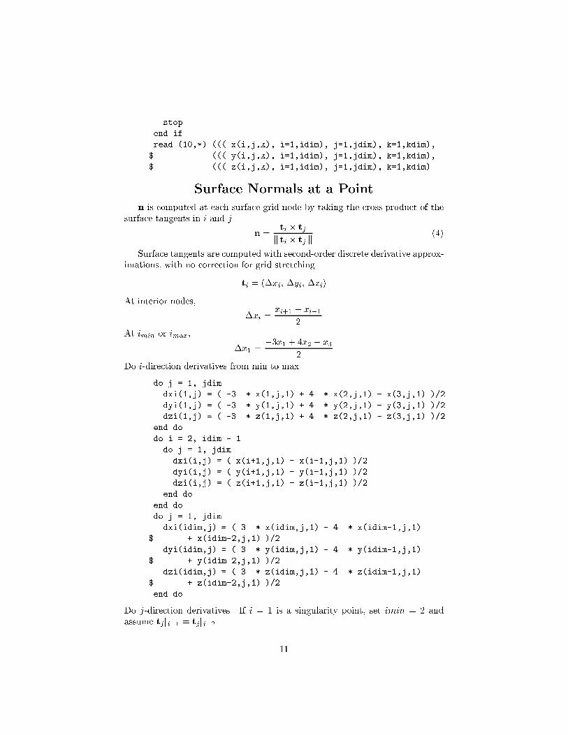
Surface Normals at a Point
n is computed at each surface grid node by taking the cross product of thesurface tangents in i and j.
n =ti � tj
k ti � tj k
(4)
Surface tangents are computed with second-order discrete derivative approx-imations, with no correction for grid stretching.
ti = (�xi; �yi; �zi)
At interior nodes,
�xi =xi+1 � xi�1
2
At imin or imax,
�x1 =�3x1 + 4x2 � x3
2
Do i-direction derivatives from min to max.
do j = 1, jdim
dxi(1,j) = ( -3. * x(1,j,1) + 4. * x(2,j,1) - x(3,j,1) )/2.
dyi(1,j) = ( -3. * y(1,j,1) + 4. * y(2,j,1) - y(3,j,1) )/2.
dzi(1,j) = ( -3. * z(1,j,1) + 4. * z(2,j,1) - z(3,j,1) )/2.
end do
do i = 2, idim - 1
do j = 1, jdim
dxi(i,j) = ( x(i+1,j,1) - x(i-1,j,1) )/2.
dyi(i,j) = ( y(i+1,j,1) - y(i-1,j,1) )/2.
dzi(i,j) = ( z(i+1,j,1) - z(i-1,j,1) )/2.
end do
end do
do j = 1, jdim
dxi(idim,j) = ( 3. * x(idim,j,1) - 4. * x(idim-1,j,1)
$ + x(idim-2,j,1) )/2.
dyi(idim,j) = ( 3. * y(idim,j,1) - 4. * y(idim-1,j,1)
$ + y(idim-2,j,1) )/2.
dzi(idim,j) = ( 3. * z(idim,j,1) - 4. * z(idim-1,j,1)
$ + z(idim-2,j,1) )/2.
end do
Do j-direction derivatives. If i = 1 is a singularity point, set imin = 2 andassume tjj i=1 = tjj i=2.
11

imin = 1
do i = imin, idim
dxj(i,1) = ( -3. * x(i,1,1) + 4. * x(i,2,1) - x(i,3,1) )/2.
dyj(i,1) = ( -3. * y(i,1,1) + 4. * y(i,2,1) - y(i,3,1) )/2.
dzj(i,1) = ( -3. * z(i,1,1) + 4. * z(i,2,1) - z(i,3,1) )/2.
end do
do j = 2, jdim - 1
do i = imin, idim
dxj(i,j) = ( x(i,j+1,1) - x(i,j-1,1) )/2.
dyj(i,j) = ( y(i,j+1,1) - y(i,j-1,1) )/2.
dzj(i,j) = ( z(i,j+1,1) - z(i,j-1,1) )/2.
end do
end do
do i = imin, idim
dxj(i,jdim) = ( 3. * x(i,jdim,1) - 4. * x(i,jdim-1,1)
$ + x(i,jdim-2,1) )/2.
dyj(i,jdim) = ( 3. * y(i,jdim,1) - 4. * y(i,jdim-1,1)
$ + y(i,jdim-2,1) )/2.
dzj(i,jdim) = ( 3. * z(i,jdim,1) - 4. * z(i,jdim-1,1)
$ + z(i,jdim-2,1) )/2.
end do
if ( imin .eq. 2 ) then
write (6,*) 'handling i=1 as pole'
do j = 1, jdim
dxj(1,j) = dxj(2,j)
dyj(1,j) = dyj(2,j)
dzj(1,j) = dzj(2,j)
end do
end if
Form the surface normals n.
do i = 1, idim
do j = 1, jdim
sn(i,j,1) = dyi(i,j) * dzj(i,j) - dzi(i,j) * dyj(i,j)
sn(i,j,2) = dzi(i,j) * dxj(i,j) - dxi(i,j) * dzj(i,j)
sn(i,j,3) = dxi(i,j) * dyj(i,j) - dyi(i,j) * dxj(i,j)
mag = sqrt(sn(i,j,1)**2 + sn(i,j,2)**2 + sn(i,j,3)**2)
sn(i,j,1) = sn(i,j,1) / mag
sn(i,j,2) = sn(i,j,2) / mag
sn(i,j,3) = sn(i,j,3) / mag
end do
end do
12

CP=CP;max at a Point
If the point is shadowed, � > �2, then CP = 0. Otherwise apply Eqns. 1
and 3.
do i = 1, idim
do j = 1, jdim
cosphi = - ( ev(1) * sn(i,j,1) + ev(2) * sn(i,j,2) +
$ ev(3) * sn(i,j,3) )
cosphi = max( 0., cosphi )
cpcpmax(i,j) = cosphi**2
end do
end do
CP;max
Compute CP;max assuming the surface pressure equals the total pressure behind
a normal shock in Eqn. 2. Using perfect gas assumptions,
CP;max =P02 � P11
2�1V 2
1
=2P1
�1V 21
�P02P1
� 1
�=
2
M21
�P02P1
� 1
�
P02P1
=( + 1)
+1
�1M2
1
2h2�2 � �1
M21
�i 1 �1
write (6,*) 'Enter Mach number and gamma'
read (5,*) amach, gamma
amach = amach**2
g1 = gamma - 1
g2 = gamma + 1
g3 = gamma
p02pi = g2**(g2/g1) * amach * 0.5 /
$ ( 2. * ( 2. * g3 - g1 / amach ) )**(1./g1)
cpmax = 2. / g3 / amach * ( p02pi - 1. )
if ( cpmax .lt. 1. .or. cpmax .gt. 2. ) then
write (6,*) '*** Problem with Cpmax = ', cpmax
else
write (6,*) 'Cpmax = ', cpmax
end if
do i = 1, idim
do j = 1, jdim
cp(i,j) = cpcpmax(i,j) * cpmax
end do
end do
Write Tecplot[13] data �le.
13
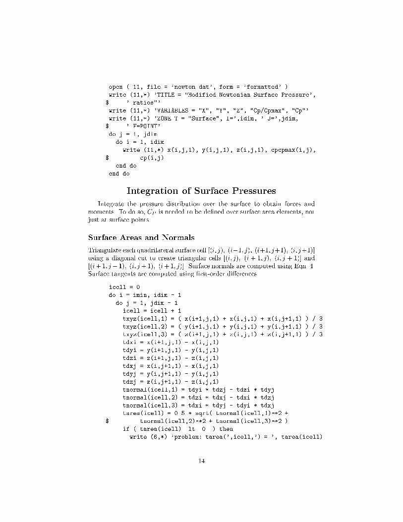
open ( 11, file = 'newton.dat', form = 'formatted' )
write (11,*) 'TITLE = "Modified Newtonian Surface Pressure',
$ ' ratios"'
write (11,*) 'VARIABLES = "X", "Y", "Z", "Cp/Cpmax", "Cp"'
write (11,*) 'ZONE T = "Surface", I=',idim, ' J=',jdim,
$ ' F=POINT'
do j = 1, jdim
do i = 1, idim
write (11,*) x(i,j,1), y(i,j,1), z(i,j,1), cpcpmax(i,j),
$ cp(i,j)
end do
end do
Integration of Surface Pressures
Integrate the pressure distribution over the surface to obtain forces and
moments. To do so, CP is needed to be de�ned over surface area elements, not
just at surface points.
Surface Areas and Normals
Triangulate each quadrilateral surface cell [(i; j); (i+1; j); (i+1; j+1); (i; j+1)]
using a diagonal cut to create triangular cells [(i; j); (i + 1; j); (i; j + 1)] and
[(i+1; j+1); (i; j+1); (i+1; j)]. Surface normals are computed using Eqn. 4.
Surface tangents are computed using �rst-order di�erences.
icell = 0
do i = imin, idim - 1
do j = 1, jdim - 1
icell = icell + 1
txyz(icell,1) = ( x(i+1,j,1) + x(i,j,1) + x(i,j+1,1) ) / 3.
txyz(icell,2) = ( y(i+1,j,1) + y(i,j,1) + y(i,j+1,1) ) / 3.
txyz(icell,3) = ( z(i+1,j,1) + z(i,j,1) + z(i,j+1,1) ) / 3.
tdxi = x(i+1,j,1) - x(i,j,1)
tdyi = y(i+1,j,1) - y(i,j,1)
tdzi = z(i+1,j,1) - z(i,j,1)
tdxj = x(i,j+1,1) - x(i,j,1)
tdyj = y(i,j+1,1) - y(i,j,1)
tdzj = z(i,j+1,1) - z(i,j,1)
tnormal(icell,1) = tdyi * tdzj - tdzi * tdyj
tnormal(icell,2) = tdzi * tdxj - tdxi * tdzj
tnormal(icell,3) = tdxi * tdyj - tdyi * tdxj
tarea(icell) = 0.5 * sqrt( tnormal(icell,1)**2 +
$ tnormal(icell,2)**2 + tnormal(icell,3)**2 )
if ( tarea(icell) .lt. 0. ) then
write (6,*) 'problem: tarea(',icell,') = ', tarea(icell)
14
stop
end if
tnormal(icell,1) = tnormal(icell,1) / 2. / tarea(icell)
tnormal(icell,2) = tnormal(icell,2) / 2. / tarea(icell)
tnormal(icell,3) = tnormal(icell,3) / 2. / tarea(icell)
end do
end do
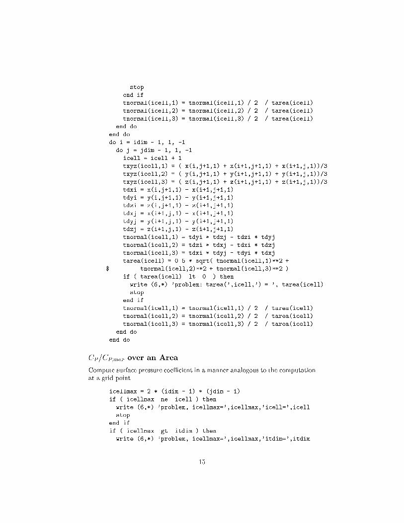
do i = idim - 1, 1, -1
do j = jdim - 1, 1, -1
icell = icell + 1
txyz(icell,1) = ( x(i,j+1,1) + x(i+1,j+1,1) + x(i+1,j,1))/3.
txyz(icell,2) = ( y(i,j+1,1) + y(i+1,j+1,1) + y(i+1,j,1))/3.
txyz(icell,3) = ( z(i,j+1,1) + z(i+1,j+1,1) + z(i+1,j,1))/3.
tdxi = x(i,j+1,1) - x(i+1,j+1,1)
tdyi = y(i,j+1,1) - y(i+1,j+1,1)
tdzi = z(i,j+1,1) - z(i+1,j+1,1)
tdxj = x(i+1,j,1) - x(i+1,j+1,1)
tdyj = y(i+1,j,1) - y(i+1,j+1,1)
tdzj = z(i+1,j,1) - z(i+1,j+1,1)
tnormal(icell,1) = tdyi * tdzj - tdzi * tdyj
tnormal(icell,2) = tdzi * tdxj - tdxi * tdzj
tnormal(icell,3) = tdxi * tdyj - tdyi * tdxj
tarea(icell) = 0.5 * sqrt( tnormal(icell,1)**2 +
$ tnormal(icell,2)**2 + tnormal(icell,3)**2 )
if ( tarea(icell) .lt. 0. ) then
write (6,*) 'problem: tarea(',icell,') = ', tarea(icell)
stop
end if
tnormal(icell,1) = tnormal(icell,1) / 2. / tarea(icell)
tnormal(icell,2) = tnormal(icell,2) / 2. / tarea(icell)
tnormal(icell,3) = tnormal(icell,3) / 2. / tarea(icell)
end do
end do
CP=CP;max over an Area
Compute surface pressure coe�cient in a manner analogous to the computation
at a grid point.
icellmax = 2 * (idim - 1) * (jdim - 1)
if ( icellmax .ne. icell ) then
write (6,*) 'problem, icellmax=',icellmax,'icell=',icell
stop
end if
if ( icellmax .gt. itdim ) then
write (6,*) 'problem, icellmax=',icellmax,'itdim=',itdim
15
stop
end if
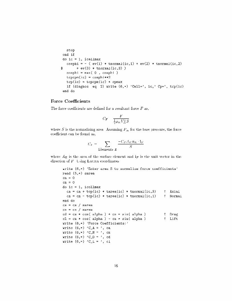
do ic = 1, icellmax
cosphi = - ( ev(1) * tnormal(ic,1) + ev(2) * tnormal(ic,2)
$ + ev(3) * tnormal(ic,3) )
cosphi = max( 0., cosphi )
tcpcpm(ic) = cosphi**2
tcp(ic) = tcpcpm(ic) * cpmax
if (diagnos .eq. 2) write (6,*) 'Cell=', ic,' Cp=', tcp(ic)
end do
Force Coe�cients
The force coe�cients are de�ned for a resultant force F as,
CF =F
1
2�1V 2
1S
where S is the normalizing area. Assuming P1 for the base pressure, the force
coe�cient can be found as,
CF =X
Elements E
�CPAE nE � iF
S
where AE is the area of the surface element and iF is the unit vector in the
direction of F . Using Laura coordinates.
write (6,*) 'Enter area S to normalize force coefficients'
read (5,*) sarea
ca = 0.
cn = 0.
do ic = 1, icellmax
ca = ca + tcp(ic) * tarea(ic) * tnormal(ic,3) ! Axial
cn = cn - tcp(ic) * tarea(ic) * tnormal(ic,1) ! Normal
end do
ca = ca / sarea
cn = cn / sarea
cd = ca * cos( alpha ) + cn * sin( alpha ) ! Drag
cl = cn * cos( alpha ) - ca * sin( alpha ) ! Lift
write (6,*) 'Force Coefficients:'
write (6,*) 'C_A = ', ca
write (6,*) 'C_N = ', cn
write (6,*) 'C_D = ', cd
write (6,*) 'C_L = ', cl
16
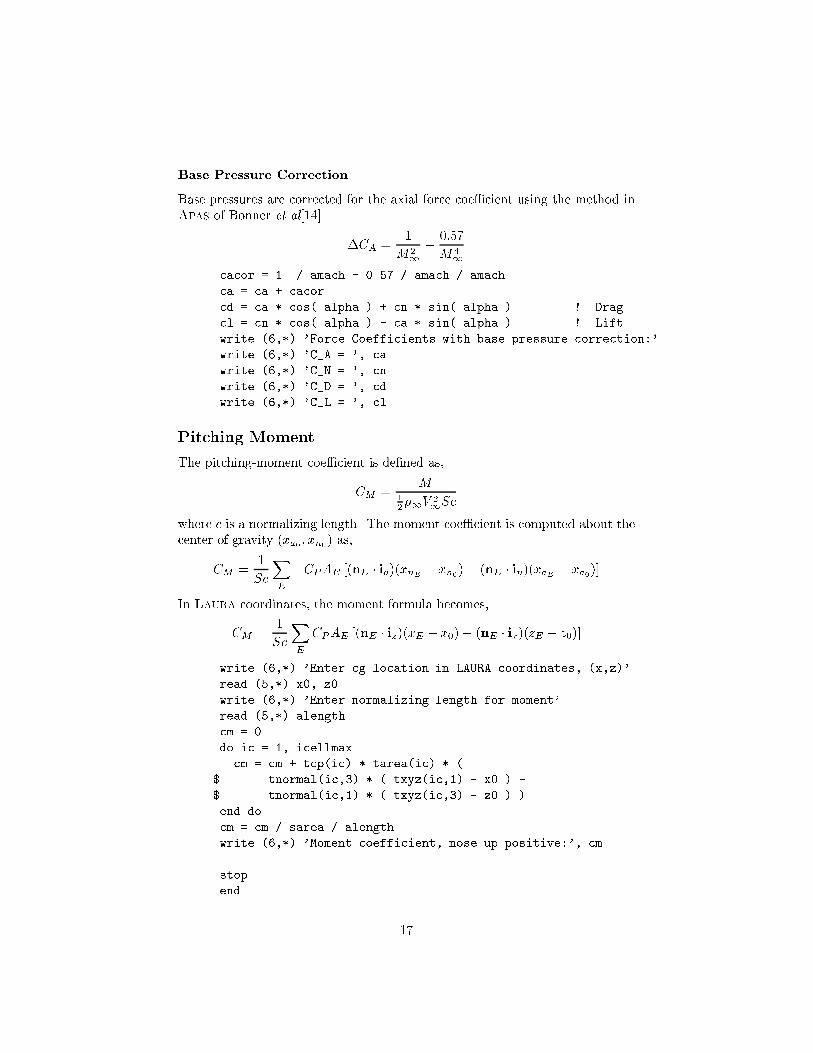
Base Pressure Correction
Base pressures are corrected for the axial force coe�cient using the method inApas of Bonner et al[14].
�CA =1
M21
�
0:57
M41
cacor = 1. / amach - 0.57 / amach / amach
ca = ca + cacor
cd = ca * cos( alpha ) + cn * sin( alpha ) ! Drag
cl = cn * cos( alpha ) - ca * sin( alpha ) ! Lift
write (6,*) 'Force Coefficients with base pressure correction:'
write (6,*) 'C_A = ', ca
write (6,*) 'C_N = ', cn
write (6,*) 'C_D = ', cd
write (6,*) 'C_L = ', cl
Pitching Moment
The pitching-moment coe�cient is de�ned as,
CM =M
1
2�1V 2
1Sc
where c is a normalizing length. The moment coe�cient is computed about thecenter of gravity (xa0 ; xn0) as,
CM =1
Sc
X
E
�CPAE [(nE � ia)(xnE � xn0 )� (nE � in)(xaE � xa0)]
In Laura coordinates, the moment formula becomes,
CM =1
Sc
X
E
CPAE [(nE � iz)(xE � x0)� (nE � ix)(zE � z0)]
write (6,*) 'Enter cg location in LAURA coordinates, (x,z)'
read (5,*) x0, z0
write (6,*) 'Enter normalizing length for moment'
read (5,*) alength
cm = 0.
do ic = 1, icellmax
cm = cm + tcp(ic) * tarea(ic) * (
$ tnormal(ic,3) * ( txyz(ic,1) - x0 ) -
$ tnormal(ic,1) * ( txyz(ic,3) - z0 ) )
end do
cm = cm / sarea / alength
write (6,*) 'Moment coefficient, nose up positive:', cm
stop
end
17
Acknowledgments
This document was prepared with LATEX2"[15] using Emacs[16] software.The Newtonian ow code presented in the appendix is a self-documented For-tran code processed through the F2latex program created by William L.Kleb.
References
[1] Atkins, K. L., Brownlee, D. E., Duxbury, T., Yen, C., and Tsou, P., \STAR-DUST: Discovery's Interstellar Dust and Cometary Sample Return Mis-sion," Proceedings from the 1997 IEEE Aerospace Conference, Feb. 1997.
[2] Wood, W. A., Gno�o, P. A., and Rault, D. F. G., \Aerodynamic Analy-sis of Commercial Experiment Transporter Re-Entry Capsule," Journal of
Spacecraft and Rockets , Vol. 33, No. 5, Sep. 1996, pp. 643{646.
[3] Wood, W. A., Gno�o, P. A., and Rault, D. F. G., \AerothermodynamicAnalysis of Commercial Experiment Transporter (COMET) Reentry Cap-sule," AIAA Paper 96{0316, Jan. 1996.
[4] Mitcheltree, R., Wilmoth, R., Cheatwood, F., Rault, D., Brauckmann,G., and Greene, F., \Aerodynamics of Stardust Sample Return Capsule,"AIAA Paper 2304, Jun. 1997.
[5] Gno�o, P. A., Gupta, R. N., and Shinn, J. L., \Conservation Equationsand Physical Models for Hypersonic Air Flows in Thermal and ChemicalNonequilibrium," NASA TP 2867, Feb. 1989.
[6] Gno�o, P. A., \An Upwind-Biased, Point-Implicit Relaxation Algorithmfor Viscous, Compressible Perfect-Gas Flows," NASA TP 2953, February1990.
[7] Roe, P. L., \Approximate Riemann Solvers, Parameter Vectors, and Di�er-ence Schemes," Journal of Computational Physics , Vol. 43, October 1981,pp. 357{372.
[8] Gno�o, P. A., \Code Calibration Program in Support of the AeroassistFlight Experiment," Journal of Spacecraft and Rockets , Vol. 27, No. 2,March-April 1990, pp. 131{142.
[9] Liu, Y. and Vinokur, M., \Equilibium Gas Flow Computations. I. Accurateand E�cient Calculation of Equilibrium Gas Properties," AIAA Paper 89{1736, Jun. 1989.
[10] Cheatwood, F. M. and Gno�o, P. A., \User's Manual for the LangleyAerothermodynamic Upwind Relaxation Algorithm (LAURA)," NASA TM4674, Apr. 1996.
18
[11] Anderson, J. D., Hypersonic and High Temperature Gas Dynamics ,
McGraw-Hill, Inc., 1989.
[12] Bertin, J. J., Hypersonic Aerothermodynamics , Education Series, AIAA,
Washington, DC, USA, 1994.
[13] Amtec Engineering, Inc., Bellevue, Washington, Tecplot User's Manual:
Version 7 , Aug. 1996.
[14] Bonner, E., Clever, W., and Dunn, K., \Aerodynamic Preliminary Analysis
System II. Part I|Theory," NASA CR 182076, Apr. 1991.
[15] Lamport, L., LATEX: A Document Preparation System|User's Guide and
Reference Manual , Addison-Wesley Publishing Company, New York, 1994.
[16] Stallman, R., GNU Emacs Manual , Free Solftware Foundation, Inc., Cam-
bridge, MA, tenth ed., Jul. 1994.
19
REPORT DOCUMENTATION PAGE Form ApprovedOMB No. 0704–0188
Public reporting burden for this collection of information is estimated to average 1 hour per response, including the time for reviewing instructions, searching existing data sources,gathering and maintaining the data needed, and completing and reviewing the collection of information. Send comments regarding this burden estimate or any other aspect of thiscollection of information, including suggestions for reducing this burden, to Washington Headquarters Services, Directorate for Information Operations and Reports, 1215 Jefferson DavisHighway, Suite 1204, Arlington, VA 22202–4302, and to the Office of Management and Budget, Paperwork Reduction Project (0704–0188), Washington, DC 20503.
NSN 7540-01-280-5500 Standard Form 298 (Rev. 2-89)Prescribed by ANSI Std. Z39-18298-102
1. AGENCY USE ONLY (Leave blank) 2. REPORT DATE
October 19973. REPORT TYPE AND DATES COVERED
Technical Memorandum
4. TITLE AND SUBTITLE
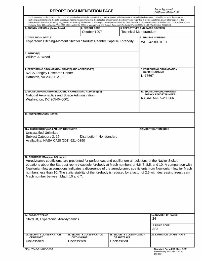
Hypersonic Pitching-Moment Shift for Stardust Reentry Capsule Forebody5. FUNDING NUMBERS
WU 242-80-01-01
6. AUTHOR(S)
William A. Wood
7. PERFORMING ORGANIZATION NAME(S) AND ADDRESS(ES)
NASA Langley Research CenterHampton, VA 23681–2199
8. PERFORMING ORGANIZATIONREPORT NUMBER
L–17667
9. SPONSORING/MONITORING AGENCY NAME(S) AND ADDRESS(ES)
National Aeronautics and Space AdministrationWashington, DC 20546–0001
10. SPONSORING/MONITORINGAGENCY REPORT NUMBER
NASA/TM–97–206266
11. SUPPLEMENTARY NOTES
12a. DISTRIBUTION/AVAILABILITY STATEMENT
Unclassified-UnlimitedSubject Category 2, 16 Distribution: NonstandardAvailability: NASA CASI (301) 621–0390
12b. DISTRIBUTION CODE
13. ABSTRACT (Maximum 200 words)
Aerodynamic coefficients are presented for perfect-gas and equilibrium-air solutions of the Navier-Stokesequations about the Stardust reentry-capsule forebody at Mach numbers of 4.6, 7, 8.5, and 10. A comparison withNewtonian-flow assumptions indicates a divergence of the aerodynamic coefficients from Newtonian-flow for Machnumbers less than 10. The static stability of the forebody is reduced by a factor of 2.5 with decreasing freestreamMach number between Mach 10 and 7.
14. SUBJECT TERMS
Stardust, Hypersonic, Aerodynamics15. NUMBER OF PAGES
24
16. PRICE CODE
A03
17. SECURITY CLASSIFICATIONOF REPORT
Unclassified
18. SECURITY CLASSIFICATIONOF THIS PAGE
Unclassified
19. SECURITY CLASSIFICATIONOF ABSTRACT
Unclassified
20. LIMITATION OF ABSTRACT