The MiniSat - Schola Europaea Luxembourg I Kirchberg · You have, for example the Arduino Uno,...
25
PROJECT N°46 1 The MiniSat Catarina Nunes European School Luxembourg I 23, Boulevard Konrad Adenauer, L-1115, Luxembourg S6 PTA Abstract Key words: Arduino Uno, Raspberry Pi, Satellite A satellite is a device designed to be launched into orbit around a celestial body. The first satellite to have been launched was Sputnik in 1957, ever since then more than a thousand satellites have been sent into Earth’s orbit. The thing is, all of these satellites cost an extreme amount of money, but what if it was possible to make them cheaper and smaller? The aim of this project is to develop a small and cheap observation satellite. In this case it will be launched up into the troposphere and collect data regarding various factors such as temperature, atmospheric pressure, humidity and light. The data will then be retrieved and analyzed using a computer program. As the data handling unit of my MiniSat I will be using either a microcontroller, such as the Arduino Uno, or a microcomputer, such as the Raspberry Pi. These components will be in charge of getting data from the sensors. The power unit will be a 9v battery. To receive the data from the satellite to my computer I will either be using a 45Hz radio transmitter and receiver, a GSM module or simply store the data in a micro SD card and retrieve it once the MiniSat has landed. The payload is composed of a set of sensors. There are multiple sensors capable of getting the data I want so I will be using the cheapest ones. I will be making a series of test in order to choose between all the options and the final product will be the cheapest, smallest and easiest to build satellite made from all these components.
Transcript of The MiniSat - Schola Europaea Luxembourg I Kirchberg · You have, for example the Arduino Uno,...

PROJECT N°46
1
The MiniSat
Catarina Nunes
European School Luxembourg I
23, Boulevard Konrad Adenauer, L-1115, Luxembourg
S6 PTA
Abstract
Key words: Arduino Uno, Raspberry Pi, Satellite
A satellite is a device designed to be launched into orbit around a celestial body. The first satellite to
have been launched was Sputnik in 1957, ever since then more than a thousand satellites have been
sent into Earth’s orbit. The thing is, all of these satellites cost an extreme amount of money, but what
if it was possible to make them cheaper and smaller?
The aim of this project is to develop a small and cheap observation satellite. In this case it will be
launched up into the troposphere and collect data regarding various factors such as temperature,
atmospheric pressure, humidity and light. The data will then be retrieved and analyzed using a
computer program.
As the data handling unit of my MiniSat I will be using either a microcontroller, such as the Arduino
Uno, or a microcomputer, such as the Raspberry Pi. These components will be in charge of getting data
from the sensors. The power unit will be a 9v battery. To receive the data from the satellite to my
computer I will either be using a 45Hz radio transmitter and receiver, a GSM module or simply store
the data in a micro SD card and retrieve it once the MiniSat has landed. The payload is composed of a
set of sensors. There are multiple sensors capable of getting the data I want so I will be using the
cheapest ones.
I will be making a series of test in order to
choose between all the options and the
final product will be the cheapest, smallest
and easiest to build satellite made from all
these components.
2
1. Introduction
A satellite is a device designed to be launched into orbit around a celestial body. The first satellite to
have ever been launched was Sputnik in 1957, ever since then more than a thousand have been sent
into Earth’s orbit. My project is about building a cheap and easy to use satellite, which is not bigger
than 0.5 cubic meters and heavier than 5 kilos, which can be used by both scientists in remote locations
in search of new physical data and hobbyists that simply want to acquire some raw data.
A normal satellite usually has two main modules: the bus or service module and the communications
module. Inside the bus module there are the following subsystems: structural subsystem, it’s the base
structure of the satellite; the telemetry subsystem (aka the data handling unit), it’s in charge of
monitoring the on-board operation and sending data back to Earth; power subsystem, an array of solar
panels which convert the sun’s light into energy for the satellite; thermal control, controls the
temperature so as to prevent any damages to the on-board equipment; and finally , the attitude and
orbit control, which controls the satellite’s orbit and attitude. The communication module is in charge
of receiving commands from Earth.
A satellite always has a mission when launching into orbit. It could be monitoring physical factor of the
Earth (temperature, humidity, cloud movement, etc.) or it could be something entirely different such
as providing cellphone service, or GPS coordinates. All of these satellites may vary in many different
ways, their weight and size, their orbit type, but one thing that they all have in common is that they
are very expensive. A typical weather satellites costs around $290 million plus the cost of maintaining
it and launching it, which my range from $10 million to $400 million.
Right now there are more than four thousand satellites orbiting the Earth, this includes those still
operating and those no longer operating.
2. Materials
To build a smaller and cheaper satellite, the MiniSat, I focused on cheaper and easy to use components,
so all of those that are listed bellow can be found on Amazon and can be put together without needing
any soldiering or complicated maneuvers.
-Computer
If you wish to make any technology related project you need a computer. In this case I needed
to program the micro controller or microcomputer that will serve as my satellite’s data handling unit.
(As long as you are able to program any computer will do).

3
-Arduino or Raspberry Pi
Every satellite needs a data handling unit, in normal cases it would be a complete computer.
In this case I am considering using a microcontroller (Arduino) or a microcomputer (Raspberry Pi). The
difference between these two is that while an Arduino is very easy to use (from my point of view) and
can only do one thing at a time a Raspberry Pi takes a fairly long time to learn how to program but can
do as much as a normal computer.
-Sensors:
Humidity and temperature: DHT11 or DHT22
There are two main easy to use and soldering free temperature and humidity sensors on the
market, theses are the DHT11 and DHT22. Both measure relative humidity by measuring the electric
resistance between two electrodes inside their cases. As humidity also depends on temperature theses
sensors have a built in thermistor for measuring temperature. Relative humidity is measured in
percentage and temperature in degrees Celsius.
DHT11: low cost (less than 5 euros), works with voltage between the range of 3 and 5 volts (meaning
it works both with the Arduino and the Raspberry Pi), has humidity readings between 20 and 80
percent (average values in Luxembourg range between 27 and 96 percent) with a 5 percent accuracy
range, has temperature readings between 0 and 50 degrees Celsius (average values in Luxembourg
range between -1 and 23 degrees Celsius) with a plus or minus 2 degrees accuracy, it takes data once
every second.
DHT22: low cost (less than 10 euros), works with voltage between the range of 3 and 5 volts (meaning
it works both with the Arduino and the Raspberry Pi), has humidity readings between 0 and 100
percent (average values in Luxembourg range between 27 and 96 percent) with a 2 percent accuracy
range, has temperature readings between -40 and 125 degrees Celsius (average values in Luxembourg
range between -1 and 23 degrees Celsius) with a plus or minus 0.5 degrees accuracy, it takes data once
every two seconds.
Light: phototransistor or photoresistor
These are two types of components which react to light. A photoresistor, as the name implies,
changes it’s resistance according to the amount of light it receives while the phototransistor varies the
amount of voltage which passes through it.
4
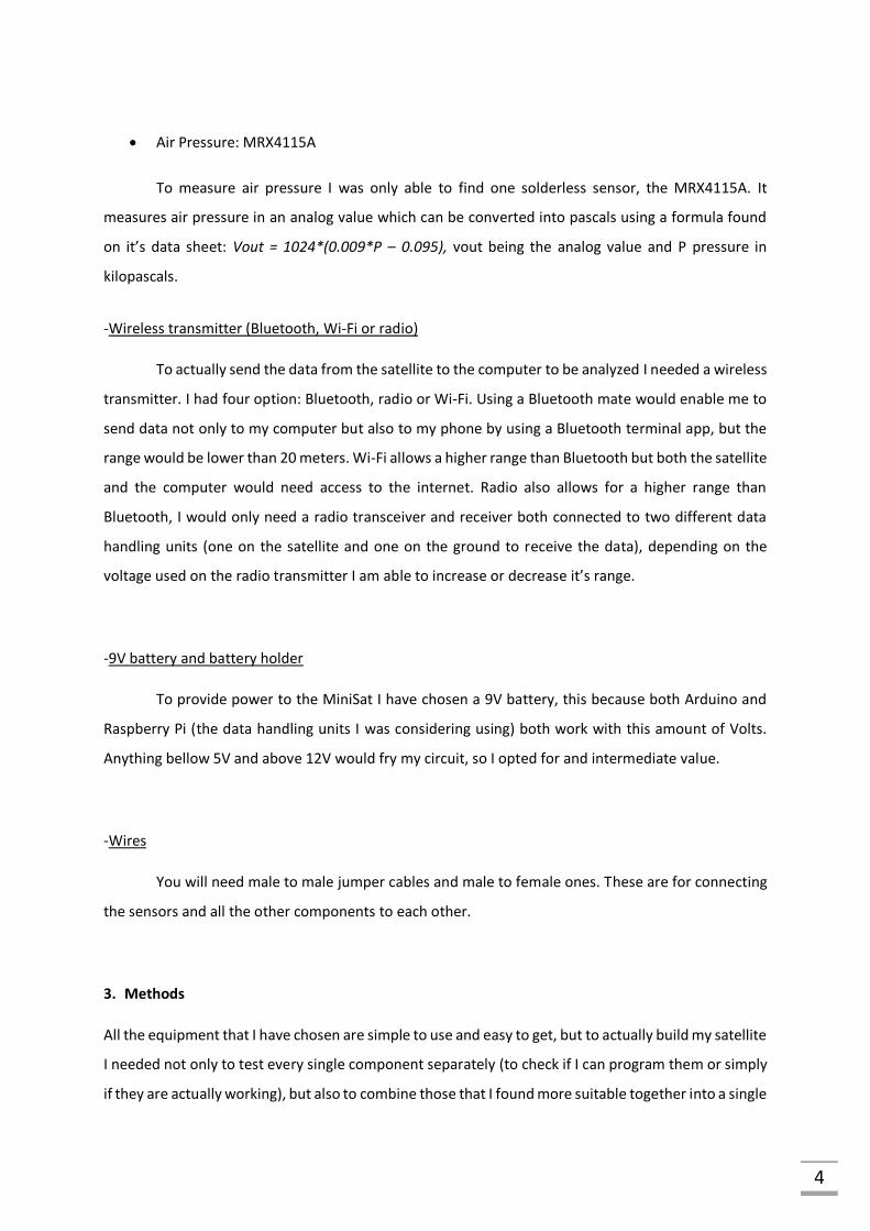
Air Pressure: MRX4115A
To measure air pressure I was only able to find one solderless sensor, the MRX4115A. It
measures air pressure in an analog value which can be converted into pascals using a formula found
on it’s data sheet: Vout = 1024*(0.009*P – 0.095), vout being the analog value and P pressure in
kilopascals.
-Wireless transmitter (Bluetooth, Wi-Fi or radio)
To actually send the data from the satellite to the computer to be analyzed I needed a wireless
transmitter. I had four option: Bluetooth, radio or Wi-Fi. Using a Bluetooth mate would enable me to
send data not only to my computer but also to my phone by using a Bluetooth terminal app, but the
range would be lower than 20 meters. Wi-Fi allows a higher range than Bluetooth but both the satellite
and the computer would need access to the internet. Radio also allows for a higher range than
Bluetooth, I would only need a radio transceiver and receiver both connected to two different data
handling units (one on the satellite and one on the ground to receive the data), depending on the
voltage used on the radio transmitter I am able to increase or decrease it’s range.
-9V battery and battery holder
To provide power to the MiniSat I have chosen a 9V battery, this because both Arduino and
Raspberry Pi (the data handling units I was considering using) both work with this amount of Volts.
Anything bellow 5V and above 12V would fry my circuit, so I opted for and intermediate value.
-Wires
You will need male to male jumper cables and male to female ones. These are for connecting
the sensors and all the other components to each other.
3. Methods
All the equipment that I have chosen are simple to use and easy to get, but to actually build my satellite
I needed not only to test every single component separately (to check if I can program them or simply
if they are actually working), but also to combine those that I found more suitable together into a single

5
circuit and program. Also, because I had more than two choices for much of my equipment and I only
wanted to use what was more useful for my project I did some tests and additional internet research
to determine which ones I should use and which ones I should discard.
Data handling unit: Arduino or Raspberry Pi
As I already knew how to program an Arduino and due to the fact that although it does only one thing
at a time it does it very quickly, I decided to work with the Arduino instead of the Raspberry Pi. There
are also various types of Arduinos. You have, for example the Arduino Uno, Arduino Yun or the Arduino
Micro. The Uno is the easiest to use and has neither Bluetooth nor Ethernet incorporated. The Yun has
both Ethernet and Wi-Fi, and the Micro has lower processing capabilities than the Uno, has neither
Ethernet nor Bluetooth unlike the Yun but is much smaller than both of the above. As the initial
prototype for my project I decided to use the Arduino Uno simply because it is the simplest Arduino to
use and has the biggest online support and libraries.
Wireless transmitter: Bluetooth, Wi-Fi or radio
Bluetooth communication requires a Bluetooth mate connected to the Arduino and, if receiving
through a phone, a Bluetooth terminal app found in any app store or, if receiving through a computer,
a special program. I already had a Bluetooth mate, but it has a range bellow 20 meters, as such, it
would not be appropriate to use on my project.
Wi-Fi communication requires a special Wi-Fi shield for Arduino or an Arduino with Wi-Fi access
integrated such as the Arduino Yun. Both these items would add extra costs to my project as it is more
expensive than Bluetooth and radio communication. Even though Wi-Fi has a higher range than both
Bluetooth and radio it is more expensive and requires access to internet in both Arduino and computer,
as such I decided that I would not use it on the MiniSat, for now.
My last option was radio. Radio requires a radio transmitter connected to the Arduino on board of the
satellite and a radio receiver connected to another Arduino which is in turn connected to the
computer. It has a lower range than Wi-Fi, but is much cheaper. It is also easier to use since I don’t
have to make a program in my computer to receive the data, I can just read it out of the serial monitor.
Radio has a higher range than Bluetooth and is also cheaper and easier to use than Wi-Fi, as such, I
decided to use radio on my project. The radio set I used was a transmitter and receiver with a radio
frequency of 433 hertz, because it had a public library on internet with all the functions I needed to
operate it.

6
To experiment with the radio I did a simple Hello World sketch both for the transmitter and receiver.
The transmitter and receiver are connected to two different Arduinos.
For the circuit first connect the 5V and Ground pins from the Arduinos to two different breadboards;
then connect the receiver and transmitter to their respective breadboard. For the receiver the first pin
(counting from the left) connects to 5V, the second to a digital pin of the Arduino (I chose pin12) and
the third to Ground. For the transmitter the first pin is connected to a digital pin of the Arduino (I chose
pin 12), the second is connected to 5V and the third to Ground.
(The whole program is in writing after the conclusion).
Sensors:
Humidity and temperature: DHT11 or DHT22
Test1- for getting the values of temperature and humidity from the DHT11
For the circuit, first connect the 5V and Ground pins from the Arduino to the breadboard; then
connect the DHT11 to any part of the breadboard; the first pin of the sensor (counting from the left
side) connects to any Digital pin of the Arduino, I chose pin 7; the second pin of the sensor connects to
the 5V and the third and last pin to Ground. Keep in mind that the order of the pins may differ from
different DHT11 sensors due to the different manufacturers.

7
The program consists of three major parts: declaring the library, the setup and the main loop.
The results are readings taken 1 second apart (due to the fact that the loop in the Arduino only
runs once every second) of both temperature and humidity.
Declaring the library:
#include <dht.h>
dht DHT;
#define DHT11_PIN 7
The first line is the actual declaration of the library (this is done every time you want to use any kind
of library not just this one. The second is the library’s object (you also use this for other libraries) and
the third line is to define which digital pin our sensor is connected to, in this case it is the seventh
digital pin.
The setup:
Serial.begin(9600);
This is for letting the Arduino communicate with the computer through a serial monitor.
The main loop:
DHT.read11(DHT11_PIN);
Serial.print("Temperature = ");
Serial.print(DHT.temperature);

8
Serial.println(" C");
Serial.print("Humidity = ");
Serial.print(DHT.humidity);
Serial.println(" %");
The first line is for getting the data from the sensor, the Arduino reads the sensor and gets the data.
Then we write in the serial monitor “Temperature” followed by it’s actual value, obtained with the
.temperature function of the DHT object. We do the same thing for the humidity readings and end the
loop. In this program there is no need for any delay since the Arduino like the DHT11 only runs the
program once every second, meaning that every time the program runs the sensor is able to take
readings.
(The whole program is in writing after the conclusion)
Test2- for comparing the two DHT sensors, DHT11 and DHT22
We use the circuit from test1 and add the DHT22 to the breadboard. The pins of my DHT22
are different from the ones of my DHT11, the first one (counting from left to right) is connected to
Ground, the second one to 5V and the third one to a digital pin, I used digital pin number 8. Keep again
in mind that the pin order depends on the sensor due to the different manufacturers.
The program is basically the same as in test1 but we define the DHT22 pin before the setup
and add the part for it’s readings in the main loop.
The readings we get appear on the serial monitor, 1 second apart due to the delay, allowing
us to compare the readings of the two sensors. The delay is used because of the fact that the DHT22
can only take readings every 2 seconds.

9
(The whole program is in writing after the conclusion)
Light: photoresistor or phototransistor
Test1- checking the amount of light with the photoresisitor
While the photoresistor does react according to the amount of light it receives it does nt tell us the
amount of light in accurate measurements in SI unities, such as lux or candela. Instead I will use to
compare the light on the ground (I am going to call it normal light) and the light during launch and
descent.
Building the circuit is fairly easy. You connect the ground a 5V from the arduino to the
breadboard (as with any other test); connect te photoresistor to any part of the breadbord; one end
of the reisitor is connected to the 5V and the other to Ground through a 10Kohm resistor and an analog
pin (I chose the A0) simultaneously.
The program, like any other arduino program, conists of three major parts: the part before the
setup (used to declare any global variabbles, libraries, etc.), the setup and the main loop. The main
loop is the real important part. Here I define the sensorValue as the reading from the resistor
andestablish the limits to my light levels: normal, weak, very weak, intense, and very intense. By
coparing the sensorValue to the initalValue I am able to compare the light at ground level, and during
ascent and descent.
(The whole program is in writing after the conclusion)
10
“Test2”- researching the phototransistor
At the beginning of my project I pondered on using a phototransistor to evaluate quantity of
light, turns out that it is not a possible option. The problem is that phototransistors are particularly
sensitive to infrared (IR) light, which the sun strongly emits, so if I ever were to use this type of
transistor to measure the quantity of light of the sun not only would I not get any readable data I would
also probably ruin the transistor. Taking this into consideration I decided not to use the phototransistor
in my project.
Air pressure: Adafruit BME280 or MRX4115A
Test1- measuring air pressure
To actually measure the air pressure I needed to convert the sensors readings, this is because
the sensor reads air pressure bur converts it into another number. To do this conversion I needed the
conversion formula which I found on the sensors data sheet:
Vout = 1024*(0.009*P – 0.095)
In this formula the P is pressure in kilopascals and the vout is the actual sensor’s reading. Through
some arithmetic rearranging the formula becomes:
P = ((Vout/1024)+0.095)/0.000009
This time P is in pascals. Since I also wanted to know if the sensor was actually working I converted the
pressure in pascals into atmospheres, so if the sensor said the air pressure equals approximately 1
atmosphere I know that my formulas are correct and the sensor is working.
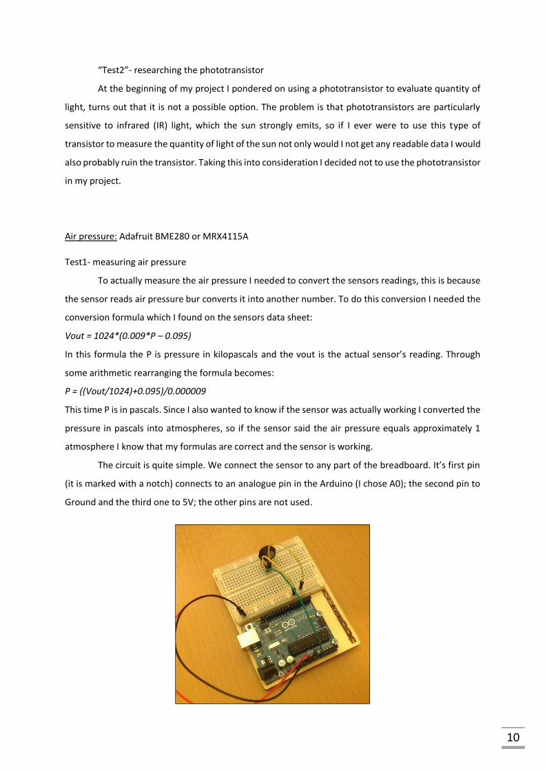
The circuit is quite simple. We connect the sensor to any part of the breadboard. It’s first pin
(it is marked with a notch) connects to an analogue pin in the Arduino (I chose A0); the second pin to
Ground and the third one to 5V; the other pins are not used.

11
The program also only involves a few global variables, the initialization of the communication
with the serial monitor in the setup; and the formulas to convert pascals into atmospheres and
millibars in the main loop.
(The whole program is in writing after the conclusion)
Altitude: combination of all sensors and hypsometric formula
To measure altitude I found a formula on the internet called the hypsometric formula. This
formula relates altitude to air pressure, sea level air pressure and temperature. For sea level air
pressure I used the average value of 101325 pascals and temperature in degrees Celsius.
𝑎𝑙𝑡𝑖𝑡𝑢𝑑𝑒 =
((101325𝑝𝑟𝑒𝑠𝑠𝑢𝑟𝑒
)
15.257
− 1)×(𝑡𝑒𝑚𝑝𝑒𝑟𝑎𝑡𝑢𝑟𝑒 + 273.15)
0.0065
The circuit is a mix of the ones I used before. Connect the DHT22 and pressure sensor like in
the previous tests and that’s it.
The only thing new to the program is the altitude formula:
altitude = ((pow(101325/pressure, 1/5.257)-1)*(temperature + 273.15))/0.0065;
To write it I needed to use an already existing function called pow, which allows me to power a number
to another number.
(The whole program is in writing after the conclusion)

12
Final Product:
To build the final circuit and program I just needed to combine all the things from the previous
tests which made quite a simple task.
The circuit:
(The whole program is in writing after the conclusion)
4. Results
Humidity and temperature test results:
After building the circuit and uploading the program what the Arduino showed me in the serial monitor
was my living room’s ambient temperature and relative humidity. At first it showed me the
temperature as 21C and humidity 46%; after 1 minute the temperature stayed the same but humidity
dropped to 45%; after 5 more minutes both temperature and humidity stayed the same. Then I blew
on the sensor and the humidity readings increased to 82%, they only returned to 45% after 280
seconds.
Through the results that I obtained I can say that the DHT11 takes a couple of minutes to adjust it’s
humidity readings, but nevertheless seems like a reliable sensor.
With the results from both tests I can conclude that both sensors are equally easy to use (they only
require installing the library), but the DHT22 is better than the DHT11. This is because the DHT22 is
more accurate when it comes to temperature (as it shows us decimals) and therefore more accurate
for humidity, since humidity depends on temperature. The DHT22 main problem is the fact that it can
only receive data every 2 seconds but due to the delay (it is optional to use delay but by using it the
data becomes clearer) that issue goes unnoticed and therefore becomes irrelevant. Concluding, while

13
the DHT11 is more compact and cheaper it is also more inaccurate than the DHT22, so I have decided
to use the DHT22 for this project.
Light test results:
Through these two tests I have concluded that the only possible way to get any accurate values on the
quantity of light would be to use an entirely different sensor that would give readings in either lux or
candela. Since I do not have access to such sensors right now I have decided to continue using the
photoresistor, but if I do acquire a sensor more adequate to this task in the future I will use it.
Air pressure test results:
Through this test I can conclude that the sensor and formulas work and are sufficiently reliable,
therefore I will be using this sensor in my project. Of course that if I find a new and better sensor I will
use it.
Altitude test results:
After building the circuit and uploading the program the serial monitor showed me an altitude
of 347 meters. Kirchberg’s (the place where I performed the experiment) actual altitude is 327 meters,
the difference between my value and the real value is most likely due to the fact that I did my
experiment inside my living room, which substantially changed the value of the temperature readings
of the DHT22. Through this test I can conclude that the hypsometric formula is good for using as long
as I keep in mind that it may show me a different value than in reality due to other factors.
Final product results:
My final result was an expected one. The circuit and program worked wonderfully after getting
rid of the bugs, and the MiniSat provided me actual accurate data of the several physical factors that I
wanted to measure.
5. Discussion
The final product seems reliable and has completed it’s objective: it is small, light, cheap and easy to
use. The next step would be figuring out how to make it rise to the troposphere (either through a
rocket, helium balloon or plane) and how it will descend down to Earth again (through a parachute).
14
The circuit and program in itself have no problems, but the MiniSat requires a case to contain the
circuit. This case would be ideally made out of a light metal such as aluminum and would be made
tailored to fit the MiniSat.
6. Conclusion
The MiniSat is a successful first prototype, but to actually use it in the field I still need to make some
improvements.
Programs:
Radio:
Receiver:
#include <VirtualWire.h>
const int receiverPin = 12;
byte message[VW_MAX_MESSAGE_LEN];
byte messageLength = VW_MAX_MESSAGE_LEN;
const int ledPin = 13;
void setup() {
Serial.begin(9600);
pinMode(ledPin, OUTPUT);
vw_set_rx_pin(receiverPin);
vw_setup(2000);
vw_rx_start();
}
15
void loop() {
digitalWrite(ledPin, LOW);
if (vw_get_message(message, &messageLength)){
digitalWrite(ledPin, HIGH);
Serial.print("Message: ");
for (int i = 0; i < messageLength; i++){
Serial.write(message[i]);
}
Serial.println();
}
}
Transmitter:
#include <VirtualWire.h>
const int transmitPin = 12;
const int ledPin = 13;
char* message = "Hello World";
void setup() {
pinMode (ledPin,OUTPUT);
vw_set_tx_pin(transmitPin);
vw_setup(2000);
}

16
void loop() {
digitalWrite(ledPin, LOW);
vw_send((uint8_t *)message, strlen(message));
vw_wait_tx();
digitalWrite(ledPin, HIGH);
delay(1000);
}
Humidity and temperature:
Test1:
#include <dht.h> dht DHT; #define DHT11_PIN 7 void setup() { Serial.begin(9600); } void loop() { DHT.read11(DHT11_PIN); Serial.print("Temperature = "); Serial.print(DHT.temperature); Serial.println(" C"); Serial.print("Humidity = "); Serial.print(DHT.humidity); Serial.println(" %"); delay(1000); }
Test2:
#include <dht.h> dht DHT;

17
#define DHT11_PIN 7 #define DHT22_PIN 8 void setup() { Serial.begin(9600); } void loop() { DHT.read11(DHT11_PIN); Serial.println("DHT11"); Serial.print("Temperature = "); Serial.print(DHT.temperature); Serial.println(" C"); Serial.print("Humidity = "); Serial.print(DHT.humidity); Serial.println(" %"); Serial.println(""); delay(1000); DHT.read22(DHT22_PIN); Serial.println("DHT22"); Serial.print("Temperature = "); Serial.print(DHT.temperature); Serial.println(" C"); Serial.print("Humidity = "); Serial.print(DHT.humidity); Serial.println(" %"); Serial.println(""); delay(1000); }
Light:
Test1
int photoPin = A0; float sensorValue; float initialValue; void setup() { Serial.begin(9600); initialValue = analogRead(photoPin); }

18
void loop() { sensorValue = analogRead(photoPin); if (sensorValue < initialValue + 100 && sensorValue > initialValue - 100){ Serial.println("light: normal"); } if (sensorValue > initialValue + 200){ Serial.println("light: very intense"); } else if (sensorValue > initialValue + 100){ Serial.println("light: intense"); } if (sensorValue < initialValue - 200){ Serial.println("light: very weak"); } else if (sensorValue < initialValue - 100){ Serial.println("light: weak"); } Serial.println(initialValue); Serial.println(sensorValue); delay(2000); }
Pressure:
const int pressurePin = A0; float pressure; float millibars; float atmospheres; float vout; float vin; void setup() { Serial.begin(9600); } void loop(){ vout = analogRead(pressurePin); pressure = ((vout/1024)+0.095)/0.000009;

19
millibars = pressure*100; atmospheres = pressure / 101325; Serial.println(); Serial.print("Pressure = "); Serial.print(pressure); Serial.println(" pa"); Serial.print("Pressure = "); Serial.print(millibars); Serial.println(" mbar"); Serial.print("Pressure = "); Serial.print(atmospheres); Serial.println("atm"); delay(1000); }
Altitude:
#include <dht.h> dht DHT; int dht22Pin = 8; int pressurePin = A1; const int ledPin = 13; float altitude; float temperature; float pressure; float vout; void setup() { Serial.begin(9600); pinMode(ledPin, OUTPUT); } void loop() { vout = analogRead(pressurePin); DHT.read22(dht22Pin); temperature = DHT.temperature; altitude = ((pow(101325/pressure, 1/5.257)-1)*(temperature + 273.15))/0.0065; Serial.print("Altitude= "); Serial.println(altitude);

20
delay(1000); }
Final Program:
#include <dht.h> #include <VirtualWire.h> dht DHT; int dht22Pin = 8; int photoPin = A0; int pressurePin = A1; const int ledPin = 13; const int transmitPin = 12; float temperature; float humidity; float sensorValue; float initialValue; float pressure; float millibars; float atmospheres; float vout; float altitude; char temp[12]; char humi[12]; char* light; char pascal[12]; char millibar[12]; char atmosphere[12]; char meters[12]; char* labelTemp = "Temperature: "; char* labelHumi = "Humidity: "; char* labelLight = "Light: "; char* labelPressure = "Pressure: "; char* labelMillibars = "Millibars: "; char* labelAtmospheres = "Atmospheres: "; char* labelAltitude = "Altitude: "; char* space = " "; void setup() { Serial.begin(9600);

21
pinMode(ledPin, OUTPUT); initialValue = analogRead(photoPin); vw_set_tx_pin(transmitPin); vw_setup(2000); } void loop() { // put your main code here, to run repeatedly: sensorValue = analogRead(photoPin); vout = analogRead(pressurePin); DHT.read22(dht22Pin); digitalWrite(ledPin, LOW); temperature = DHT.temperature; humidity = DHT.humidity; sendTemp(); sendHumi(); sendLight(); sendAirPressure(); sendAltitude(); delay(1000); digitalWrite(ledPin, HIGH); } void sendTemp(){ dtostrf(temperature, 13, 2, temp); Serial.write(temp); Serial.println(); vw_send((uint8_t*)labelTemp, strlen(labelTemp)); vw_wait_tx(); vw_send((uint8_t*)temp, strlen(temp)); vw_wait_tx(); vw_send((uint8_t*)space, strlen(space)); vw_wait_tx(); } void sendHumi(){ dtostrf(humidity, 13, 2, humi); Serial.write(humi);

22
Serial.println(); vw_send((uint8_t*)labelHumi, strlen(labelHumi)); vw_wait_tx(); vw_send((uint8_t*)humi, strlen(humi)); vw_wait_tx(); vw_send((uint8_t*)space, strlen(space)); vw_wait_tx(); } void sendLight(){ if (sensorValue < initialValue + 100 && sensorValue > initialValue - 100){ Serial.println("light: normal"); digitalWrite(ledPin, HIGH); light = "normal "; vw_send((uint8_t*)labelLight, strlen(labelLight)); vw_wait_tx(); vw_send((uint8_t*)light, strlen(light)); vw_wait_tx(); vw_send((uint8_t*)space, strlen(space)); vw_wait_tx(); } if (sensorValue > initialValue + 200){ Serial.println("light: very intense"); digitalWrite(ledPin, HIGH); light = "very intense "; vw_send((uint8_t*)labelLight, strlen(labelLight)); vw_wait_tx(); vw_send((uint8_t*)light, strlen(light)); vw_wait_tx(); vw_send((uint8_t*)space, strlen(space)); vw_wait_tx(); } else if (sensorValue > initialValue + 100){ Serial.println("light: intense"); digitalWrite(ledPin, HIGH); light = "intense "; vw_send((uint8_t*)labelLight, strlen(labelLight)); vw_wait_tx();
23
vw_send((uint8_t*)light, strlen(light)); vw_wait_tx(); vw_send((uint8_t*)space, strlen(space)); vw_wait_tx(); } if (sensorValue < initialValue - 200){ Serial.println("light: very weak"); digitalWrite(ledPin, HIGH); light = "very weak "; vw_send((uint8_t*)labelLight, strlen(labelLight)); vw_wait_tx(); vw_send((uint8_t*)light, strlen(light)); vw_wait_tx(); vw_send((uint8_t*)space, strlen(space)); vw_wait_tx(); } else if (sensorValue < initialValue - 100){ Serial.println("light: weak"); digitalWrite(ledPin, HIGH); light = "weak "; vw_send((uint8_t*)labelLight, strlen(labelLight)); vw_wait_tx(); vw_send((uint8_t*)light, strlen(light)); vw_wait_tx(); vw_send((uint8_t*)space, strlen(space)); vw_wait_tx(); } } void sendAirPressure(){ pressure = ((vout/1024)+0.095)/0.000009; millibars = pressure*100; atmospheres = pressure / 101325; dtostrf(pressure, 13, 2, pascal); vw_send((uint8_t*)labelPressure, strlen(labelPressure)); vw_wait_tx(); vw_send((uint8_t*)pascal, strlen(pascal)); vw_wait_tx(); vw_send((uint8_t*)space, strlen(space));
24
vw_wait_tx(); dtostrf(millibars, 13, 2, millibar); vw_send((uint8_t*)labelMillibars, strlen(labelMillibars)); vw_wait_tx(); vw_send((uint8_t*)millibar, strlen(millibar)); vw_wait_tx(); vw_send((uint8_t*)space, strlen(space)); vw_wait_tx(); dtostrf(atmospheres, 13, 2, atmosphere); vw_send((uint8_t*)labelAtmospheres, strlen(labelAtmospheres)); vw_wait_tx(); vw_send((uint8_t*)atmosphere, strlen(atmosphere)); vw_wait_tx(); vw_send((uint8_t*)space, strlen(space)); vw_wait_tx(); } void sendAltitude(){ altitude = ((pow(101325/pressure, 1/5.257)-1)*(temperature + 273.15))/0.0065; dtostrf(altitude, 13, 2, meters); vw_send((uint8_t*)labelAltitude, strlen(labelAltitude)); vw_wait_tx(); vw_send((uint8_t*)meters, strlen(meters)); vw_wait_tx(); vw_send((uint8_t*)space, strlen(space)); vw_wait_tx(); }

25
7. Acknowledgements
I would like to thank my biology teacher Manuela Pereira for her support and guidance; I would also
like to thank my father for his advice.
8. References
http://keisan.casio.com/exec/system/1224585971
https://weatherspark.com/averages/28839/Luxembourg
https://ccollins.wordpress.com/2013/12/11/how-to-measure-air-pressure-with-arduino/
http://www.farnell.com/datasheets/8723.pdf
https://learn.adafruit.com/dht/using-a-dhtxx-sensor
http://www.circuitbasics.com/how-to-set-up-the-dht11-humidity-sensor-on-an-arduino/
http://playground.arduino.cc/Main/DHTLib
http://www.micro4you.com/files/sensor/DHT11.pdf
https://learn.adafruit.com/measuring-light-with-a-beaglebone-black/you-will-need?view=all
https://learn.adafruit.com/photocells/overview?view=all
https://en.wikipedia.org/wiki/Lux
https://en.wikipedia.org/wiki/Lumen_(unit)
http://learn.parallax.com/tutorials/robot/shield-bot/robotics-board-education-shield-
arduino/chapter-6-light-sensitive-15
https://en.wikipedia.org/wiki/Photoresistor
http://www.instructables.com/id/RF-315433-MHz-Transmitter-receiver-Module-and-
Ardu/?ALLSTEPS
http://www.buildcircuit.com/how-to-use-rf-module-with-arduino/
http://www.pjrc.com/teensy/td_libs_VirtualWire.html
http://www.airspayce.com/mikem/arduino/VirtualWire/
http://randomnerdtutorials.com/rf-433mhz-transmitter-receiver-module-with-arduino/
http://www.instructables.com/id/Arduino-weather-station-with-RF433-MHz-modules/?ALLSTEPS


![Data Arduino UNO [Unlocked by Www.freemypdf.com]](https://static.fdocuments.us/doc/165x107/55cf98ae550346d033990fba/data-arduino-uno-unlocked-by-wwwfreemypdfcom.jpg)