The meriGauge plus system - Test Equipment Depot · It is not possible for Meriam to identify all...
41
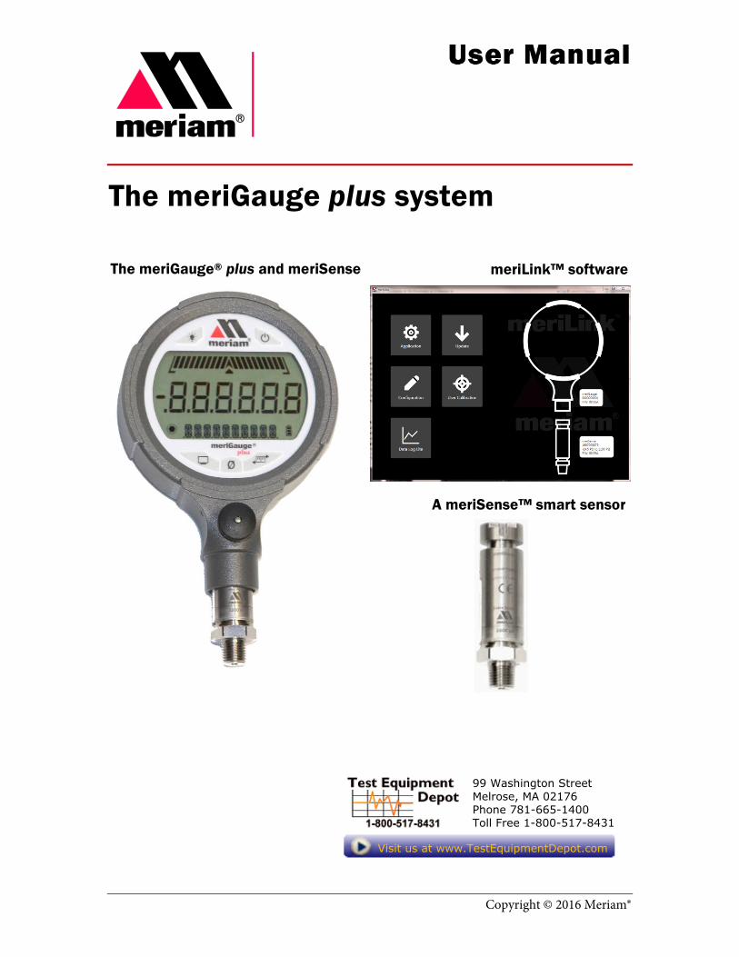
Copyright © 2016 Meriam® The meriGauge plus system The meriGauge ® plus and meriSense meriLink™ software A meriSense™ smart sensor 99 Washington Street Melrose, MA 02176 Phone 781-665-1400 Toll Free 1-800-517-8431 Visit us at www.TestEquipmentDepot.com
Transcript of The meriGauge plus system - Test Equipment Depot · It is not possible for Meriam to identify all...
Copyright © 2016 Meriam®
The meriGauge plus system
The meriGauge® plus and meriSense meriLink™ software
A meriSense™ smart sensor
99 Washington Street Melrose, MA 02176 Phone 781-665-1400Toll Free 1-800-517-8431
Visit us at www.TestEquipmentDepot.com

9R479-A June 2016
meriGauge plus System User Manual 2
Introductory information
Notification Statements
Disclaimer Every precaution has been taken in the preparation of this manual. Nevertheless, Meriam assumes no responsibility for errors or omissions or any damages resulting from the use of the information contained in this publication, including, without limitation, incidental, special, direct or consequential damages. MERIAM MAKES NO REPRESENTATIONS OR WARRANTIES WITH RESPECT TO THE ACCURACY OR COMPLETENESS OF THE CONTENTS HEREOF AND SPECIFICALLY DISCLAIMS ANY IMPLIED WARRANTIES OF MERCHANTABILITY OR FITNESS FOR ANY PARTICULAR PURPOSE. Meriam reserves the right to revise this publication and to make changes from time to time in the content hereof without obligation to notify any person of such revision or changes.
In no event shall Meriam be liable for any indirect, special, incidental, consequential, or punitive damages or for any lost profits arising out of or relating to any services provided by Meriam or its affiliates.
It is not possible for Meriam to identify all foreseeable uses or misuses, therefore all persons involved in commissioning, using, or maintaining this product must satisfy their self that each intended application is acceptable.
Copyright This publication is proprietary to Meriam and no ownership rights are transferred. Neither this manual, nor any of the material contained herein, may be reproduced without the prior written consent of Meriam.

9R479-A June 2016
meriGauge plus System User Manual 3
Trademark information
Trademarks statements meriGauge® plus, meriSense™, and meriLink™ are trademarks of Meriam.
All other trademarks are the property of their respective owners.
Safety Information
Preventing injuryFailure to follow all instructions could result in injury:
• Read.• Understand.• Follow all safety warnings and instructions provided with
this product.• Meet or exceed your employer’s safety practices.
Safety SymbolsThe following table defines the safety symbols, signal words, and corresponding safety messages used in the manual. These symbols:
• Identify potential hazards.• Warn you about hazards that could result in personal
injury or equipment damage.

9R479-A June 2016
meriGauge plus System User Manual 4
Safety Symbols
Safety Symbols Explaining the symbols This is the Read Instruction Manual symbol. This symbol indicates that you must read the instruction manual.
Indicates a potentially hazardous situation which, if not avoided, will result in death or serious injury.
Indicates a potentially hazardous situation which, if not avoided, could result in death or serious injury.
Indicates a potentially hazardous situation which, if not avoided, could result in minor or moderate injury.
Indicates information essential for proper product installation, operation or maintenance.
General Purpose
General Purpose use only • Never use General Purpose gauges in hazardous areas.• Never use General Purpose sensors in hazardous areas.• General Purpose gauges and sensors are a fire or explosion
hazard.• Do not substitute components because they may impair
operation and safety.

9R479-A June 2016
meriGauge plus System User Manual 5
Sample labels for General Purpose gauges
General Purpose—meriGauge plus label See the figure of a sample General Purpose label.
General Purpose—meriSense Absolute label See the figure of a sample General Purpose label below.
General Purpose—meriSense Compound label See the sample General Purpose figure label below.
Serial Number Model Number
Seria
l Num
ber
Mod
el N
umbe
r Se
rial N
umbe
r M
odel
Num
ber

9R479-A June 2016
meriGauge plus System User Manual 6
Contents
Introductory information ..................................2
Notification Statements ...................... 2
Trademark ........................................... 3
Safety Information .............................. 3
Safety Symbols .................................... 4
General Purpose ................................. 4
Sample labels for General Purpose gauges ................................................. 5
Meriam Contact Information .............. 7
Glossary ............................................... 8
The meriSense detachable sensors ................9
Make a pressure connection .............. 9
Protect your sensors from dust .......... 9
Accuracy Statement for meriSense (MS700x-xxxxxx) ................................ 10
Accuracy Statement (continued) ...... 11
Pressure reference chart .................. 12
Inspect the vent on the sensors ....... 13
The meriGauge plus gauge ............................ 14
Batteries ............................................ 14
Batteries (continued) ........................ 15
Connect the gauge to a sensor ........ 15
The display ......................................... 16
Backlight in the LCD display ............. 17
Display modes ................................... 17
Zero the meriGauge plus in Display mode .................................................. 18
The Data Log mode ........................... 19
List of Engineering Units ................... 20
Information key ................................. 21
Auto Off (Automatic shutoff) ............. 21
Prepare the meriGauge plus for storage ............................................... 22
The meriLink software .................................. 23
Installation instructions for meriLink ........................................................... 23
Part 1: Install USB device drivers .... 23
Part 2: Install USB device drivers .... 24
Overview of meriLink ........................ 25
Connection status ............................ 27
Buttons .............................................. 28
Passwords ......................................... 29
Passwords (continued)..................... 30
Request a recovery password ......... 30
User Calibration—For qualified personnel only .................................. 31
Configuration for meriGauge plus ... 32
Configuration for meriSense............ 33
Preview the data log ......................... 34
Data log files ..................................... 35
Data log files (continued) ................. 36
Appendices ................................................... 37
Returning for repair or calibration .. 37
Troubleshooting Checklist ............... 38
Specifications ................................... 39
Hazardous Material and Recycling Compliance ....................................... 40
Part numbers .................................... 41

9R479-A June 2016
meriGauge plus System User Manual 7
99 Washington Street Melrose, MA 02176 Phone 781-665-1400Toll Free 1-800-517-8431
Visit us at www.TestEquipmentDepot.com

9R479-A June 2016
meriGauge plus System User Manual 8
Glossary Words and phrases Definitions
Absolute Isolated pressure (AI)
Absolute pressure is equal to the sum of these two: 1. Gauge pressure.2. Atmospheric pressure
(also known as barometric pressure).
Button or key • A button always refers to an area on the screen that you canclick to select functionality.
• A key always refers to hardware push-buttons on the keyboardthat you can press.
Compound Isolated pressure (CI)
A compound gauge can display both positive and negative (vacuum) pressures. The meriGauge plus System replaces the need for buying one gauge for each sensor: 1. A pressure sensor.2. A vacuum sensor.
Firmware Firmware is a type of software that is stored on hardware. Both meriGauge plus and meriSense have firmware. meriLink is a software application that can communicate with their firmware and change or update it as needed.
Isolated The word isolated refers to the sensing element being isolated from the media. It is commonly used in the phrases Absolute Isolated (AI) pressure and Compound Isolated (CI) pressure.
Meriam Calibration Meriam calibration refers to any calibration completed at Meriam with Meriam traceability. Meriam calibration includes: • Oven calibration.• Multipoint Meriam adjustment.
User Calibration User calibration refers to any calibration done outside of Meriam with non-Meriam traceability. User calibration includes: • Multipoint user calibration or adjustment.

9R479-A June 2016
meriGauge plus System User Manual 9
The meriSense detachable sensors
Make a pressure connection
Make a good NPT connection Each meriSense detachable sensor has a 316 stainless steel
1/4 in. male NPT connection for direct mounting.
• The threads should be coated with a pipe sealant compound before installation.
• Tighten to finger tight plus 1.5 turns to 3 turns using a 23 mm (7/8 in.) wrench with the notch facing the same direction as you intend for the display.
Use only a wrench on the hex fitting
Never rotate a meriSense sensor by turning the meriGauge plus gauge.
Protect your sensors from dust
Keep the dust cap on sensors Make sure you put the dust cap on the sensor to protect the
electrical contacts after the meriGauge plus gauge has been detached from the sensor.

9R479-A June 2016
meriGauge plus System User Manual 10
Accuracy Statement for meriSense (MS700x-xxxxxx) Range limits
Sensor pressure ranges MS700 meriSense Contact [email protected] to purchase these parts and for more information about the following part numbers: + 1 216 281 1100 or (800) 817-7849.
MS700 meriSense sensors
Part number Ranges Type
ZMS700-AI0015 0 psi to 15 psi Absolute
ZMS700-CI0015 –15 psi to 15 psi Compound
ZMS700-AI0030 0 psi to 30 psi Absolute
ZMS700-CI0030 –15 psi to 30 psi Compound
ZMS700-AI0100 0 psi to 100 psi Absolute
ZMS700-CI0100 –15 psi to 100 psi Compound
ZMS700-CI0300 –15 psi to 300 psi Compound
ZMS700-CI0500 –15 psi to 500 psi Compound
ZMS700-CI1000 –15 psi to 1 000 psi Compound
ZMS700-CI3000 –15 psi to 3 000 psi Compound
• Includes all combined effects of linearity, repeatability, hysteresis, stability, and temperature over the specified calibrated temperature range for one year.
• Not recommended for continuous use below 0.02 psi absolute.
Media compatibility 316 SS
Temperature limits
Operating temperature –10 °C to 50 °C (14 °F to 122 °F)
• Up to 95 % RH non-condensing. • No change in accuracy over operating temperature range. • Gauge must be zeroed to achieve rated specification.
Process temperature –10 °C to 50 °C (14 °F to 122 °F)
Warm-up time Five (5) minutes.

9R479-A June 2016
meriGauge plus System User Manual 11
Accuracy Statement (continued) Pressure measurements
Absolute 0 % to 110 % of Range: ± (0.02 % of Full Scale) + 0 % to 110 % of Range: (0.005 % of Reading)
Compound 0 % to 110 % of Range: ± (0.02 % of Full Scale) +
0 % to 110 % of Range: (0.005 % of Reading)
Vacuum*: ± (0.02 % of Full Scale) *Vacuum = –14.5 psi
Pressure limits
Pressure limits • Do not exceed the pressure limits listed in the sensor pressure
ranges section for the MS700 meriSense. • Failure to operate within the specified pressure limits could
result in injury.
Overrange limit
Overrange pressure means the value is outside the calibrated upper or lower range.
• Up to 110 % of range, meriGauge plus displays the accurate pressure.
• Above 110 %, it flashes red. This indicates that the applied pressure exceeds the calibrated range.
Note: If the calibrated pressure range is exceeded, the pressure displayed may not be accurate
• Above 120 %, it flashes red and displays dashes.
Overpressure limits
Overpressure is the point at which permanent damage (deformation) may occur to the sensor.
Burst pressure limit Burst pressure is four (4) times the rated pressure. It is the point at which the sensor may mechanically leak.

9R479-A June 2016
meriGauge plus System User Manual 12
Pressure reference chart
Pressure Reference Chart The following chart contrasts the differences between the
Absolute and Compound sensors.

9R479-A June 2016
meriGauge plus System User Manual 13
Inspect the vent on the sensors
Do not block vent 1. If the vent becomes blocked, it will cause inaccurate
measurements. 2. Meriam recommends that you visually inspect the vent
area each time you use the meriSense to make sure it is not blocked.

9R479-A June 2016
meriGauge plus System User Manual 14
The meriGauge plus gauge
Batteries
Install the batteries 1. Turn over the meriGauge plus so the display faces down.
2. Remove the four screws on the battery cover with the Phillips head screwdriver by turning them counterclockwise.
3. Insert the four AA batteries.
Note: Pay attention to the positive (+) and negative (−) battery polarity markings at the bottom of the compartment.
4. Replace the battery cover.
5. To secure the cover, torque the screws clockwise 0.56 N-m (5 in-lbs) maximum.
Know your batteries
The meriGauge plus is powered by four 1.5 volt AA size batteries.
• Never mix batteries—not by manufacturer or by size, by capacity, or by chemistry.
• Never mix old and new batteries. • Remove all four batteries in the meriGauge plus at the
same time. • Replace all four batteries with batteries from the same
package or with the same expiration date.

9R479-A June 2016
meriGauge plus System User Manual 15
Batteries (continued)
Watch for the low battery indicators The battery indicator on the display shows the current charge.
Note: Be prepared to change batteries when you see the outline of the battery icon when the outline of the battery icon flashes.
Using the Backlight reduces your battery life
Turn it off to optimize battery life.
Refer to the battery manufacturer’s instructions
Visit the website of the battery manufacturer to learn more about the care, storage, shipping, use, disposal, and recycling of your batteries.
Insert good batteries before beginning…
• Insert good batteries before data logging or conducting a
Rate of Change. • Insert good batteries before modifying or updating your
meriGauge plus gauge or meriSense sensor.
Connect the gauge to a sensor
Connect meriGauge plus to meriSense • The notch on the sensor must face the same direction as
the meriGauge plus for the sensor to lock in place. • Simply slide the gauge housing on the meriSense until it
fully connects.

9R479-A June 2016
meriGauge plus System User Manual 16
The display
The keys
The bar graph
• The bar graph displays a live indication of the current pressure applied to the sensor as a % of Full Scale.
• When the Information key is pressed, the bar graph displays the remaining state of the charge for the batteries.

9R479-A June 2016
meriGauge plus System User Manual 17
Backlight in the LCD display
White backlight The white backlight has an automatic timeout. If no keys have
been pressed, the backlight automatically turns off after 1 minute.
Note: You can configure the backlight timeout with meriLink.
Levels of backlight intensity
Press the Backlight key to cycle through the choices:
• Low.
• Medium.
• High.
• Off.
Flashing red backlight
• The flashing red backlight indicates an error condition.
• Possible error conditions are:
o Pressure has exceeded the calibrated accuracy of the meriSense.
o Pressure has fallen below the stated accuracy of the meriSense.
• The red backlight overrides the white backlight.
Display modes
Nine (9) display modes Some modes below have characters in parentheses. The
characters in bold display on the meriGauge plus.
1. Normal 5. Tare (T.OFF, T.ON)
2. Min (MIN) 6. Average (AVG)
3. Max (MAX) 7. Rate of change per minute (RATE)
4. Accuracy (+/–) 8. Data Log Lite (DATA LOG)
9. Time & Temperature

9R479-A June 2016
meriGauge plus System User Manual 18
Zero the meriGauge plus in Display mode
In normal measure mode
If the sensor is within a tolerance band around zero, press and hold the Zero key to zero the pressure measurement and to reset the Min and Max measurements.
Note: The tolerance band is approximately ± 1 % of the Full Scale pressure value of the sensor.
In Min or Max mode
Press and hold the Zero key to reset the Min and Max measurement. However, this does not zero the pressure measurement.
In Tare mode
When the Tare is off (T.OFF), press and hold the Zero key to turn on Tare (T.ON) and to set the Tare value at the current pressure measurement.
Likewise, when the Tare is on (T.ON), press and hold the Zero key to turn off the Tare mode.
In Average mode
Press and hold the Zero key to restart the rolling average.
In Data Log mode
Press and hold the Zero key until you see –STARTING—appear on the LCD display to start recording a new data log.
Holding the Zero key
The key must be held to perform the Zero or Tare function. The displayed value(s) dashes out during the zero or tare process.

9R479-A June 2016
meriGauge plus System User Manual 19
The Data Log mode
View the “BATT %” before you begin Data Log Lite runs up to one hour.
Note: Do not start data log if the outline of the battery icon is flashing.
Only one data set at a time
Data Log Lite can record and hold only one data set at a time.
Note: When you press and hold the Zero key while DATA LOG appears in the LCD display, a new data set begins to record over the existing data set.
Start the data logging process
1. Press the Display key until you see Data Log appear in the LCD display.
2. Press and hold the Zero key until you see –STARTING--. The data log symbol starts to flash indicating it is recording data. Data Log Lite records data every 15 seconds for one hour.
3. –COMPLETE—appears after one hour.
Note: Auto Off is suspended during data logging. If you selected 5 Minutes for Auto Off, then meriGauge plus remains on for one hour and 5 minutes and then turns off.
Complete the data logging process
Here are some of the actions that can complete the data logging process before the one hour:
• Press and hold the Zero key until you see --STOPPING--. • Press the Power key to turn off the meriGauge plus. • Remove the meriGauge plus from a sensor. • Connect the meriGauge plus to the meriLink.

9R479-A June 2016
meriGauge plus System User Manual 20
List of Engineering Units
Engineering units are stored in a sensor • Each meriSense sensor stores a complete list of
engineering units. • meriLink software gives you the ability to configure
specific engineering units to specific sensors. • The meriGauge plus displays whatever units were
previously selected on individual sensors. • When the meriSense pressure sensors are shipped, the
common 12 engineering units are available. These 12 units appear in bold type in the Standard Units list below.
Standard Units (non-custom) 1. PSI 2. INW20C 3. INW4C 4. INW60F 5. FTW20C 6. FTW4C 7. FTW60F 8. MMW20C 9. MMW4C 10. MMW60F 11. CMW20C
12. CMW4C 13. CMW60F 14. MW20C 15. MW4C 16. MW60F 17. INHG0C 18. MHG0C 19. CMHG0C 20. MMHG0C 21. TORR 22. KG/CM2
23. KG/M2 24. PA 25. HPA 26. KPA 27. MPA 28. BAR 29. MBAR 30. ATM 31. OZ/IN2 32. LB/FT2
Engineering units can be changed on a sensor
• You must use meriLink software to select or deselect the Standard Units on a particular sensor from the list above.
• By pressing the Units key on the meriGauge plus, you cycle through all the configured units within the currently attached meriSense.

9R479-A June 2016
meriGauge plus System User Manual 21
Information key
The Information key is in the red triangle of the Meriam logo
The information key displays:
Icon Explanation
The Information key (the red triangle inside the Meriam logo) displays the following: • BATT % displays the percentage on the bar
graph and in digits. • CAL DATE is the date on which the
meriSense sensor was calibrated by Meriam. • USL displays the Upper Specification Limit on
the sensor. • LSL displays the Lower Specification Limit on
the sensor. • LT MAX % displays the Life-Time Maximum
that has been reached on the sensor.
Auto Off (Automatic shutoff)
How long will the gauge remain on if I leave it unattended?
• The default setting is Always On. • You can configure the timeout for the Auto Off with
meriLink.
The timeout for Automatic Shutoff is suspended
• The timeout for the Auto Off is suspended during data logging sessions to prevent an accidental loss of information.
• Auto Off is automatically re-instated after data logging is completed.

9R479-A June 2016
meriGauge plus System User Manual 22
Prepare the meriGauge plus for storage
Remove the batteries to store the gauge
1. Remove the batteries from the meriGauge plus to store it
for 30 days or more. 2. Follow the battery manufacturer’s instructions for storing
your batteries.
Store the meriGauge plus
The recommended storage temperature for the meriGauge plus is between –20 ºC to 70 ºC (–4 ºF to 158 ºF).

9R479-A June 2016
meriGauge plus System User Manual 23
The meriLink software
Install meriLink from the CD
Follow the on-screen directions On the meriGauge plus CD, in the folder called
meriLink installer, right click Setup.exe and select Run as Administrator. Follow the on-screen instructions.
Part 1: Install USB device drivers
Do you have a 32 bit or 64 bit computer system? You need to select the right USB device driver for your system
so follow the steps on this page.
If… Then…
You already know what version you have,
Begin on the next page: Part 2: Install USB…
You don’t know what version you have,
Continue with step 1.
1. Click this link http://support.microsoft.com/kb/827218
and this Microsoft website appears.
2. Scroll down until you see the Automatic version detection results box.
Note: Microsoft displays the type of system your computer has, in this example 32-bit.

9R479-A June 2016
meriGauge plus System User Manual 24
Part 2: Install USB device drivers from the CD
For 64-bit systems On the meriGauge plus CD:
• Open the folder called USB Drivers and open the subfolder called 64bit.
• Double click Installer.exe and follow the on-screen instructions.
For 32-bit systems
On the meriGauge plus CD:
• Open the folder called USB Drivers and open the subfolder called 32bit.
• Double click Installer.exe and follow the on-screen instructions.

9R479-A June 2016
meriGauge plus System User Manual 25
Overview of meriLink
Compatible versions of Microsoft Windows meriLink is compatible with these three versions:
• Microsoft Windows 7 with Microsoft .NET Framework 4.5 or newer.
• Microsoft Windows 8.1 with Microsoft .NET Framework 4.5 or newer.
• Microsoft Windows 10 with Microsoft .NET Framework 4.5 or newer. Note: Right click the meriLink app in the Start menu. Click More and select Run as Administrator.
USB cable and your computer
Connect the USB cable to meriGauge plus and to your computer in order to configure meriGauge plus and meriSense using the meriLink software.
Watch for the battery outline
Do not attempt to modify or update your meriGauge plus or meriSense when only the outline of the battery icon is visible..
Watch for the Yellow dot on a tab
A yellow dot appears on a tab in meriLink to indicate that you have made changes to settings but you have not saved them yet.
Click the Write button to save the changes you made.

9R479-A June 2016
meriGauge plus System User Manual 26
Overview of meriLink (continued)
Year-Month-Date format
Date format meriLink displays the date in year-month-day format.
For example: 2016-04-22 (YYYY-MM-DD).
Hours:Minutes:Seconds format
Time format meriLink displays the time in Universal Coordinated Time
(UTC) 24-hour format.
For example: 15:05:45 UTC (hours:minutes:seconds).

9R479-A June 2016
meriGauge plus System User Manual 27
Connection status
Attached devices meriLink displays the outlines of attached devices on the right
with descriptions appearing alongside. See the figure below.
No sensor attached Notice the bold outline of meriGauge plus contrasted with the
dotted outline of an unattached meriSense. See the figure below.
No attached devices
meriLink displays no outlines of devices on the right side. See the figure below.

9R479-A June 2016
meriGauge plus System User Manual 28
Buttons
meriLink buttons The function buttons are described below.
Icons Descriptions
The Application screen displays: • About. • Language Selection. • Available Software Update.
The Update screen displays two sections: • The meriGauge section. • The meriSense section.
Note: These sections alert you to new software updates for gauge and for each attached sensor.
The Configuration screen displays two tabs: • meriGauge or the name you assigned to it. • meriSense or the name you assigned to it.
Note: These tabs offer you various settings to configure each device.
The User Calibration screen displays: • Live Reading. • Restore Factory Defaults. • Choose Calibration Unit. • Begin and Apply calibration. • Factory Calibration Information. • User Calibration Information.
The Data Log Lite button displays data log information and sensor information.

9R479-A June 2016
meriGauge plus System User Manual 29
Passwords
Overview of passwords Passwords are not required to use the meriGauge plus or
meriSense.
• Each device (meriGauge plus or meriSense) can have its own unique 16-character password. You may use from 1-16 characters: letters, numbers, or symbols, and uppercase and lowercase.
• Each device can have its password enabled or disabled independently from any other device.
• meriLink retrieves the passwords stored on the meriGauge plus and meriSense.
meriLink uses the password on meriGauge
If you choose to enable the Password Required For Future
Access feature, then meriLink will request a password for the following actions:
• To modify a gauge’s configuration. This action includes saving to or loading from a file.
• To update the software on a gauge.
meriLink uses the password on meriSense
If you choose to enable the Password Required For Future
Access, then meriLink will request a password for the following actions:
• To modify the sensor’s configuration. This action includes saving to or loading from file.
• To update the software on the sensor. • To calibrate the sensor.

9R479-A June 2016
meriGauge plus System User Manual 30
Passwords (continued)
meriLink requests a password If you choose to enable the Password Required For Future
Access, then meriLink will request a password whenever you modify a configuration, update software, or calibrate a device.
• Once meriLink accepts a password for one of those actions, the device remains unlocked until it is disconnected.
• If you enter the password on one screen, meriLink unlocks that device on its other screens as well.
Data Log Lite does not use a password
meriLink does not use a password since Data Log Lite does not make changes.
Request a recovery password
Forgot the password for a device? If you forget a password, contact Meriam to generate a
recovery password for you to unlock the device.
A recovery password disables the password until you turn it back on. meriLink will prompt you to enter a new password.
Contact Meriam.
Only valid one day
The recovery password is only valid during a specified date.

9R479-A June 2016
meriGauge plus System User Manual 31
User Calibration—For qualified personnel only
What does “Calibration Enabled” refer to? • With a check in the Calibration Enabled box, the
meriSense reports readings with the user calibration applied.
• The Live Reading values always reflect the current setting of Calibration Enabled in the meriSense.
Restore Factory Defaults
This button clears your user calibration from the meriSense.
Choose Calibration Unit
• Select the calibration reference units. • This does not affect or depend on the configuration units.
Begin button…Apply button
1. Click Begin. 2. Select the point. 3. Apply reference pressure within the range shown. 4. Enter the reference value. 5. Save the point. 6. Repeat steps 2-5 until you are done.
(You have to change at least one point.) 7. Click the Apply button.

9R479-A June 2016
meriGauge plus System User Manual 32
Configuration for meriGauge plus
The Name field You can assign your own company designations to each
meriGauge plus.
Sync PC time to Gauge
• Click to update meriGauge time and date with your computer.
• The display and data logging use this time and date.
Timeouts
• Backlight – default setting is 1 Minute. • Auto Off (Automatic Off) – default setting is Always On.
Display Functions: Enable or Disable
• Min/Max • Accuracy • Tare • Average • Rate of Change • Time & Temp • Allow zero adjust (ø)
As Left/As Found Configuration Report Required: Microsoft Word is required to run this report.
You can review a summary of the configuration of the gauge when it is first connected and the changes you made in the As
Found/As Left Report for meriGauge plus.
Open and Save / Read and Write Configurations
• Save refers to saving new configuration data to a file on your computer and Open refers to opening configuration data that you saved on your computer.
• Read and Write refer to reading configuration data from a meriGauge plus or writing to it.

9R479-A June 2016
meriGauge plus System User Manual 33
Configuration for meriSense
The Name field You can assign your own company designations to each
meriGauge, asset number, naming scheme, and so on.
Enabled Units
Select or deselect the engineering units to view on the meriGauge plus display.
Two User Defined Units
Users can define text and multiplier for two non-standard or unsupported display units.
Note: multiplier × PSI = the displayed value.
As Left/As Found Configuration Report
You can review a summary of the configuration of the sensor when it is first connected and the changes you made in the As
Found/As Left Report for meriSense.
Open and Save / Read and Write Configurations
• Save refers to saving new configuration data to a file on your computer and Open refers to opening configuration data that you saved on your computer.
• Read and Write refer to reading configuration data from a meriGauge plus or writing to it.

9R479-A June 2016
meriGauge plus System User Manual 34
Preview the data log
Preview window The Preview window displays the first 10 samples so you can
confirm the data to save. If you have fewer than 10, it displays all of your samples.
Status, pressure, and temperature
The Status
• The symbol corresponds to readings that are within the calibrated range.
• The symbol indicates a reading that is out of range and the value should not be considered reliable.
• The symbol indicates a reading is out of range and no value is available.
The Pressure
The pressure indicates the reading at each 15-second interval in the data set.
The Temperature
The temperature indicates approximate ambient temperature at each 15-second interval in the data set.
Note: See the figure below as an example of what the preview window may look like.

9R479-A June 2016
meriGauge plus System User Manual 35
Data log files
Save the log file The Save button in Data Log Lite saves the data to a
Tab Separated Values (*.TSV) file format.
Import the log file into Microsoft® Excel®
Use Excel (or other spreadsheet or database programs) to import the TSV file so you can see the formatted data log.
Directions for Excel 2010 (later versions are similar):
8. Open a new, blank workbook in Excel. 9. Click the Data tab. 10. Click the From Text button. 11. Click the Text Files (*.prn;*.txt;*.csv) arrow
and select All Files (*.*). 12. Navigate to find the TSV file that you saved. 13. Select the file and click the Import button.
The Text Import Wizard appears and guides you through three steps.
14. Click the Next button (in Step 1 of 3). 15. Click the Next button (in Step 2 of 3). 16. Click the Finish button (in Step 3 of 3) and the Import
Data window displays. 17. Click the OK button to place the data in the Existing
worksheet in cell $A$1.
Note: You may use other spreadsheet or database software to import TSV files. Some word processing software can import the data but text editors (Notepad is one example of a text editor.) may require extra effort to format the data.

9R479-A June 2016
meriGauge plus System User Manual 36
Data log files (continued)
Look for page breaks if you want to print Excel has a feature called Page Break Preview to show you
where the page breaks occur in the log file. Change the page breaks, rows to repeat at the top, and other settings as necessary so your printers do not waste paper.
Note: Other spreadsheet software offer similar features.

9R479-A June 2016
meriGauge plus System User Manual 37
Appendices
Returning for repair or calibration First — Request a Number
In the event that a meriGauge plus or meriSense requires service and must be returned, please contact Meriam using one of the methods listed in the following table to request a Return Material Authorization (RMA) number:
Return Material Authorization
Do not send any unit for repair unless you contacted Meriam for a Return Material Authorization (RMA) number. Important: If you have not received this number and have not clearly marked it on the package being shipped back, we will return the unit at your expense. The Meriam Service & Repair Department will provide you with this number when you complete the website form, fax or e-mail your information. An RMA number must accompany all incoming packages to insure proper tracking, processing, and repair work.
Questions? Call Meriam
US Customers (800) 817-7849
International customers + 1 216 281 1100
Ship the box to
Meriam 10920 Madison Avenue Cleveland, Ohio 44102 USA
99 Washington Street Melrose, MA 02176 Phone 781-665-1400Toll Free 1-800-517-8431
Visit us at www.TestEquipmentDepot.com

9R479-A June 2016
meriGauge plus System User Manual 38
Troubleshooting Checklist
The words “No Sensor” display on the gauge Follow these steps to troubleshoot the meriGauge plus connection with meriSense sensor when the message No Sensor appears:
1. Turn off the meriGauge plus gauge.2. Remove the gauge from the sensor.3. Re-attach the gauge to the sensor.
Note: The notch on the sensor must be positioned the samedirection as the gauge face for the sensor to lock in place. (Youmay hear it click when it locks in place.)
Note: The locking pin prevents the gauge from accidentallydisconnecting from the sensor.
4. Turn on the meriGauge plus gauge.
Note: If the preceding steps don’t work, contact Meriam Sales:

9R479-A June 2016
meriGauge plus System User Manual 39
Specifications
Display Specifications
Display rate The meriGauge plus displays five (5) updates per second.
LCD screen • The LCD displays six (6) digits.• The numerical display height is 17.8 mm (0.7 in.)
Dimensional Specifications
The meriGauge plus gauge with the meriSense smart sensor

9R479-A June 2016
meriGauge plus System User Manual 40
Material specifications
meriGauge plus housing The meriGauge plus housing is made of these two types of aluminum:
• A356 Aluminum.• 6061 Aluminum.
meriSense The meriSense is made from 300 series stainless steel.
Hazardous Material and Recycling Compliance Compliant with European Directives
This product is compliant with these European directives:
Directive Description
RoHS Directive 2011/65/EU
Reduction of Hazardous Substances
WEEE 2012/19/EU
Waste from Electrical and Electronic Equipment
Note: The following marking indicates that you must not discard this electrical / electronic product in domestic household waste.

9R479-A June 2016
meriGauge plus System User Manual 41
Part numbers
Part Numbers Descriptions
Z9P273 USB Cable
Z9P1055 Protective Boot
Z9A1354 Hard carrying case
Z9A878 4-pack of batteries